US9124798B2 - Systems and methods for illuminating an iris with visible light for biometric acquisition - Google Patents
Systems and methods for illuminating an iris with visible light for biometric acquisitionDownload PDFInfo
- Publication number
- US9124798B2 US9124798B2US13/473,468US201213473468AUS9124798B2US 9124798 B2US9124798 B2US 9124798B2US 201213473468 AUS201213473468 AUS 201213473468AUS 9124798 B2US9124798 B2US 9124798B2
- Authority
- US
- United States
- Prior art keywords
- eye
- visible light
- light source
- iris
- biometric
- Prior art date
- Legal status (The legal status is an assumption and is not a legal conclusion. Google has not performed a legal analysis and makes no representation as to the accuracy of the status listed.)
- Expired - Fee Related, expires
Links
Images


Classifications
- G—PHYSICS
- G06—COMPUTING OR CALCULATING; COUNTING
- G06V—IMAGE OR VIDEO RECOGNITION OR UNDERSTANDING
- G06V40/00—Recognition of biometric, human-related or animal-related patterns in image or video data
- G06V40/10—Human or animal bodies, e.g. vehicle occupants or pedestrians; Body parts, e.g. hands
- G06V40/18—Eye characteristics, e.g. of the iris
- G06V40/19—Sensors therefor
- H04N5/23212—
- G06K9/00604—
Definitions
- the present disclosurerelates to identity verification technologies, and more specifically to systems and methods for illuminating an iris with visible light for biometric acquisition.
- Iris recognitionis typically performed using infra-red illumination, as described by Oaugman for example. J. Daugman, “High confidence visual recognition of persons by a test of statistical independence,” PAMI, 15(11):1148-1161, 1993.
- Infra-red (IR) lightdoes not irritate or cause discomfort to a subject as much as visible light.
- IR lightis suitable for penetrating layers of the iris and illuminating features of the iris suitable for biometric matching or verification. The use of IR light may require a custom camera and/or illumination components which may be costly in comparison to visible light sources.
- While some camerasmay be equipped with or accompanied by one or more visible light sources (e.g., to produce a flash) to illuminate a scene or object for example, these light sources may be very bright. When directed at the eye, light from such sources may irritate or cause discomfort to the subject. Infra-red illumination, on the other hand, is invisible to the user, and may avoid such issues.
- visible lightwhen used for image acquisition, corneal reflections of surrounding objects are often imaged and captured as artifacts. Attempts to remove the corneal reflections have been performed, but these approaches are dependent on the environment and so performance may be unpredictable.
- An example of this approachis “Separating Reflections in Human iris Images for Illumination”, Wang, H., Lin, S., Liu, X., and Kang, S. B. In Proceedings of ICCV. 2005, 16911698.
- the present disclosureis directed to an apparatus for acquiring biometric information of an individual.
- the apparatusmay include a light source directing visible light towards an eye.
- the light sourcemay direct visible light towards an eye at a first angle that avoids a light-sensitive portion of the eye's retina.
- the visible lightmay have an intensity level that would cause discomfort to the eye if directed at the light-sensitive portion of the retina.
- the visible lightmay have an intensity level that exceeds the intensity level of other visible light incident on the cornea.
- the light sourcemay direct the visible light at an angle of at least 30 degrees from a line of sight of the eye.
- the visible lightmay be incident upon a surface of the iris.
- the visible lightmay illuminate the iris for biometric acquisition.
- the visible lightmay illuminate substantially the whole iris for biometric acquisition.
- the visible lightmay have an intensity level above that which causes discomfort to the eye if the visible light reaches a light-sensitive part of the eye's retina.
- the light sourcemay have an intensity level that exceeds the intensity of visible ambient light incident on the cornea.
- a sensormay acquire iris biometric data from the illuminated iris.
- the light sourcecomprises a point light source directing a visible light beam at the eye.
- the light sourcemay comprise directing a visible light beam at the eye, the visible light beam having a full width half brightness (FWHB) of less than 90 degrees.
- the light sourcemay direct visible light comprising non-isotropic illumination at the eye.
- the visible light beammay have full width at half brightness (FWHB) of less than 90 degrees.
- the apparatusmay include a mobile device.
- the light source and the sensormay be incorporated on the mobile device.
- the light sourcemay be mounted on a frame or device worn over the individual's eye, face or head.
- the light sourcemay direct the visible light towards a non-nasal side of the eye.
- the apparatusmay include an illuminated screen or second visible light source for dilating the pupil.
- the visible light beammay have a full width at half brightness (FWHB) of less than 90 degrees.
- the visible lightmay comprise a cone of visible illumination and may be of sufficient intensity to illuminate the whole iris via light diffusion within a portion of the eye.
- the light sourcemay direct visible light of sufficient intensity to illuminate striations of the iris for biometric acquisition.
- the light sourcemay direct the visible light at an angle that avoids reaching a light-sensitive portion of the eye's retina.
- the light sourcedirects, towards the eye, visible light having an intensity level below a threshold limit for safe exposure to the eye.
- the light sourcemay be positioned to avoid illumination of a surface of the eye as the user positions the device for use.
- the light sourcemay be directionally positioned to avoid illumination of the eye as the user adjusts the apparatus for use, until the apparatus is positioned within a suitable spatial region for biometric acquisition.
- the apparatusmay include a channel for shaping visible light from the light source into a visible light beam for illuminating the iris.
- the apparatusincludes a screen providing visual cues to suitably position the light source relative to the eye for the biometric acquisition.
- the apparatusmay include an audio feedback module providing audio cues to suitably position the light source relative to the eye for the biometric acquisition.
- the present disclosureis directed to method for acquiring biometric information of an individual.
- a light source of a biometric acquisition apparatusmay direct visible light towards an eye at a first angle that avoids a light-sensitive portion of the eye's retina.
- the visible lightmay illuminate the iris for biometric acquisition and may have an intensity level that (i) would cause discomfort to the eye if directed at the light-sensitive portion of the retina and (ii) exceeds the intensity level of other visible light incident on the cornea.
- a sensor of the biometric acquisition apparatusmay acquire iris biometric data from the illuminated iris.
- the light sourcedirects the visible light from a mobile biometric acquisition device on which the sensor is mounted.
- the light sourcemay direct the visible light from a frame or device worn over the individual's eye, face or head.
- the light sourcemay direct the visible light from and/or towards the non-nasal side of the eye.
- the light sourcemay direct the visible light that includes non-isotropic illumination at the eye.
- the biometric acquisition apparatusmay include and/or use an illuminated screen or second visible light source to constrict the pupil.
- FIG. 1Ais a block diagram illustrative of an embodiment of a networked environment with a client machine that communicates with a server;
- FIGS. 1B and 1Care block diagrams illustrative of embodiments of computing machines for practicing the methods and systems described herein;
- FIG. 2Adepicts a schematic layout of an eye in which visible illumination or light is directed towards the eye
- FIG. 2Bdepicts one embodiment of a method for providing visible illumination to an iris for biometric acquisition
- FIGS. 3-7depict embodiments of methods and systems for providing visible illumination to an iris for biometric acquisition
- FIGS. 8 and 9depict embodiments of a frame or device hosting a visible light source and worn or positioned over the eye.
- FIG. 10depicts one embodiment of a method for illuminating an iris with visible light for biometric acquisition.
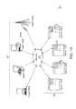
- FIG. 1Aillustrates one embodiment of a computing environment 101 that includes one or more client machines 102 A- 102 N (generally referred to herein as “client machine(s) 102 ”) in communication with one or more servers 106 A- 106 N (generally referred to herein as “server(s) 106 ”). Installed in between the client machine(s) 102 and server(s) 106 is a network.
- the computing environment 101can include an appliance installed between the server(s) 106 and client machine(s) 102 .
- This appliancecan mange client/server connections, and in some cases can load balance client connections amongst a plurality of backend servers.
- the client machine(s) 102can in some embodiment be referred to as a single client machine 102 or a single group of client machines 102
- server(s) 106may be referred to as a single server 106 or a single group of servers 106 .
- a single client machine 102communicates with more than one server 106
- a single server 106communicates with more than one client machine 102
- a single client machine 102communicates with a single server 106 .
- a client machine 102can, in some embodiments, be referenced by any one of the following terms: client machine(s) 102 ; client(s); client computer(s); client device(s); client computing device(s); local machine; remote machine; client node(s); endpoint(s); endpoint node(s); or a second machine.
- the server 106in some embodiments, may be referenced by any one of the following terms: server(s), local machine; remote machine; server farm(s), host computing device(s), or a first machine(s).
- the client machine 102can in some embodiments execute, operate or otherwise provide an application that can be any one of the following: software; a program; executable instructions; a virtual machine; a hypervisor; a web browser; a web-based client; a client-server application; a thin-client computing client; an ActiveX control; a Java applet; software related to voice over internet protocol (VoIP) communications like a soft IP telephone; an application for streaming video and/or audio; an application for facilitating real-time-data communications; a HTTP client; a FTP client; an Oscar client; a Telnet client; or any other set of executable instructions.
- Still other embodimentsinclude a client device 102 that displays application output generated by an application remotely executing on a server 106 or other remotely located machine. In these embodiments, the client device 102 can display the application output in an application window, a browser, or other output window.
- the applicationis a desktop, while in other embodiments the application is an application that generates a desktop.
- the computing environment 101can include more than one server 106 A- 106 N such that the servers 106 A- 106 N are logically grouped together into a server farm 106 .
- the server farm 106can include servers 106 that are geographically dispersed and logically grouped together in a server farm 106 , or servers 106 that are located proximate to each other and logically grouped together in a server farm 106 .
- Geographically dispersed servers 106 A- 106 N within a server farm 106can, in some embodiments, communicate using a WAN, MAN, or LAN, where different geographic regions can be characterized as: different continents; different regions of a continent; different countries; different states; different cities; different campuses; different rooms; or any combination of the preceding geographical locations.
- the server farm 106may be administered as a single entity, while in other embodiments the server farm 106 can include multiple server farms 106 .
- a server farm 106can include servers 106 that execute a substantially similar type of operating system platform (e.g., WINDOWS NT, manufactured by Microsoft Corp. of Redmond, Wash., UNIX, LINUX, or SNOW LEOPARD.)
- the server farm 106can include a first group of servers 106 that execute a first type of operating system platform, and a second group of servers 106 that execute a second type of operating system platform.
- the server farm 106in other embodiments, can include servers 106 that execute different types of operating system platforms.
- the server 106can be any server type.
- the server 106can be any of the following server types: a file server; an application server; a web server; a proxy server; an appliance; a network appliance; a gateway; an application gateway; a gateway server; a virtualization server; a deployment server; a SSL VPN server; a firewall; a web server; an application server or as a master application server; a server 106 executing an active directory; or a server 106 executing an application acceleration program that provides firewall functionality, application functionality, or load balancing functionality.
- a server 106may be a RADIUS server that includes a remote authentication dial-in user service.
- Some embodimentsinclude a first server 106 A that receives requests from a client machine 102 , forwards the request to a second server 106 B, and responds to the request generated by the client machine 102 with a response from the second server 106 B.
- the first server 106 Acan acquire an enumeration of applications available to the client machine 102 and well as address information associated with an application server 106 hosting an application identified within the enumeration of applications.
- the first server 106 Acan then present a response to the client's request using a web interface, and communicate directly with the client 102 to provide the client 102 with access to an identified application.
- Client machines 102can, in some embodiments, be a client node that seeks access to resources provided by a server 106 .
- the server 106may provide clients 102 or client nodes with access to hosted resources.
- the server 106functions as a master node such that it communicates with one or more clients 102 or servers 106 .
- the master nodecan identify and provide address information associated with a server 106 hosting a requested application, to one or more clients 102 or servers 106 .
- the master nodecan be a server farm 106 , a client 102 , a cluster of client nodes 102 , or an appliance.
- One or more clients 102 and/or one or more servers 106can transmit data over a network 104 installed between machines and appliances within the computing environment 101 .
- the network 104can comprise one or more sub-networks, and can be installed between any combination of the clients 102 , servers 106 , computing machines and appliances included within the computing environment 101 .
- the network 104can be: a local-area network (LAN); a metropolitan area network (MAN); a wide area network (WAN); a primary network 104 comprised of multiple sub-networks 104 located between the client machines 102 and the servers 106 ; a primary public network 104 with a private sub-network 104 ; a primary private network 104 with a public sub-network 104 ; or a primary private network 104 with a private sub-network 104 .
- LANlocal-area network
- MANmetropolitan area network
- WANwide area network
- a primary network 104comprised of multiple sub-networks 104 located between the client machines 102 and the servers 106 ; a primary public network 104 with a private sub-network 104 ; a primary private network 104 with a public sub-network 104 ; or a primary private network 104 with a private sub-network 104 .
- Still further embodimentsinclude a network 104 that can be any of the following network types: a point to point network; a broadcast network; a telecommunications network; a data communication network; a computer network; an ATM (Asynchronous Transfer Mode) network; a SONET (Synchronous Optical Network) network; a SDH (Synchronous Digital Hierarchy) network; a wireless network; a wireline network; or a network 104 that includes a wireless link where the wireless link can be an infrared channel or satellite band.
- a network 104can be any of the following network types: a point to point network; a broadcast network; a telecommunications network; a data communication network; a computer network; an ATM (Asynchronous Transfer Mode) network; a SONET (Synchronous Optical Network) network; a SDH (Synchronous Digital Hierarchy) network; a wireless network; a wireline network; or a network 104 that includes a wireless link where the wireless link can be
- the network topology of the network 104can differ within different embodiments, possible network topologies include: a bus network topology; a star network topology; a ring network topology; a repeater-based network topology; or a tiered-star network topology. Additional embodiments may include a network 104 of mobile telephone networks that use a protocol to communicate among mobile devices, where the protocol can be any one of the following: AMPS; TDMA; CDMA; GSM; GPRS UMTS; 3G; 4G; or any other protocol able to transmit data among mobile devices.
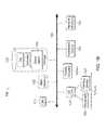
- FIG. 1BIllustrated in FIG. 1B is an embodiment of a computing device 100 , where the client machine 102 and server 106 illustrated in FIG. 1A can be deployed as and/or executed on any embodiment of the computing device 100 illustrated and described herein.
- a system bus 150that communicates with the following components: a central processing unit 121 ; a main memory 122 ; storage memory 128 ; an input/output (I/O) controller 123 ; display devices 124 A- 124 N; an installation device 116 ; and a network interface 118 .
- the storage memory 128includes: an operating system, software routines, and a client agent 120 .
- the I/O controller 123in some embodiments, is further connected to a key board 126 , and a pointing device 127 .
- Other embodimentsmay include an I/O controller 123 connected to more than one input/output device 130 A- 130 N.
- FIG. 1Cillustrates one embodiment of a computing device 100 , where the client machine 102 and server 106 illustrated in FIG. 1A can be deployed as and/or executed on any embodiment of the computing device 100 illustrated and described herein.
- a system bus 150that communicates with the following components: a bridge 170 , and a first I/O device 130 A.
- the bridge 170is in further communication with the main central processing unit 121 , where the central processing unit 121 can further communicate with a second I/O device 130 B, a main memory 122 , and a cache memory 140 .
- I/O portsI/O ports
- a memory port 103a main processor.
- Embodiments of the computing machine 100can include a central processing unit 121 characterized by any one of the following component configurations: logic circuits that respond to and process instructions fetched from the main memory unit 122 ; a microprocessor unit, such as: those manufactured by Intel Corporation; those manufactured by Motorola Corporation; those manufactured by Transmeta Corporation of Santa Clara, Calif.; the RS/6000 processor such as those manufactured by International Business Machines; a processor such as those manufactured by Advanced Micro Devices; or any other combination of logic circuits.
- a central processing unit 121characterized by any one of the following component configurations: logic circuits that respond to and process instructions fetched from the main memory unit 122 ; a microprocessor unit, such as: those manufactured by Intel Corporation; those manufactured by Motorola Corporation; those manufactured by Transmeta Corporation of Santa Clara, Calif.; the RS/6000 processor such as those manufactured by International Business Machines; a processor such as those manufactured by Advanced Micro Devices; or any other combination of logic circuits.
- central processing unit 122may include any combination of the following: a microprocessor, a microcontroller, a central processing unit with a single processing core, a central processing unit with two processing cores, or a central processing unit with more than one processing core.
- FIG. 1Cillustrates a computing device 100 that includes a single central processing unit 121
- the computing device 100can include one or more processing units 121 .
- the computing device 100may store and execute firmware or other executable instructions that, when executed, direct the one or more processing units 121 to simultaneously execute instructions or to simultaneously execute instructions on a single piece of data.
- the computing device 100may store and execute firmware or other executable instructions that, when executed, direct the one or more processing units to each execute a section of a group of instructions. For example, each processing unit 121 may be instructed to execute a portion of a program or a particular module within a program.
- the processing unit 121can include one or more processing cores.
- the processing unit 121may have two cores, four cores, eight cores, etc.
- the processing unit 121may comprise one or more parallel processing cores.
- the processing cores of the processing unit 121may in some embodiments access available memory as a global address space, or in other embodiments, memory within the computing device 100 can be segmented and assigned to a particular core within the processing unit 121 .
- the one or more processing cores or processors in the computing device 100can each access local memory.
- memory within the computing device 100can be shared amongst one or more processors or processing cores, while other memory can be accessed by particular processors or subsets of processors.
- the multiple processing unitscan be included in a single integrated circuit (IC).
- ICintegrated circuit
- the processorscan execute a single instruction simultaneously on multiple pieces of data (SIMD), or in other embodiments can execute multiple instructions simultaneously on multiple pieces of data (MIMD).
- SIMDsingle instruction simultaneously on multiple pieces of data
- MIMDmultiple instructions simultaneously on multiple pieces of data
- the computing device 100can include any number of SIMD and MIMD processors.
- the computing device 100can include an image processor, a graphics processor or a graphics processing unit.
- the graphics processing unitcan include any combination of software and hardware, and can further input graphics data and graphics instructions, render a graphic from the inputted data and instructions, and output the rendered graphic.
- the graphics processing unitcan be included within the processing unit 121 .
- the computing device 100can include one or more processing units 121 , where at least one processing unit 121 is dedicated to processing and rendering graphics.
- One embodiment of the computing machine 100includes a central processing unit 121 that communicates with cache memory 140 via a secondary bus also known as a backside bus, while another embodiment of the computing machine 100 includes a central processing unit 121 that communicates with cache memory via the system bus 150 .
- the local system bus 150can, in some embodiments, also be used by the central processing unit to communicate with more than one type of I/O device 130 A- 130 N.
- the local system bus 150can be any one of the following types of buses: a VESA VL bus; an ISA bus; an EISA bus; a MicroChannel Architecture (MCA) bus; a PCI bus; a PCI-X bus; a PCI-Express bus; or a NuBus.
- MCAMicroChannel Architecture
- computing machine 100examples include an I/O device 130 A- 130 N that is a video display 124 that communicates with the central processing unit 121 . Still other versions of the computing machine 100 include a processor 121 connected to an I/O device 130 A- 130 N via any one of the following connections: HyperTransport, Rapid I/O, or InfiniBand. Further embodiments of the computing machine 100 include a processor 121 that communicates with one I/O device 130 A using a local interconnect bus and a second I/O device 130 B using a direct connection.
- the computing device 100includes a main memory unit 122 and cache memory 140 .
- the cache memory 140can be any memory type, and in some embodiments can be any one of the following types of memory: SRAM; BSRAM; or EDRAM.
- Other embodimentsinclude cache memory 140 and a main memory unit 122 that can be any one of the following types of memory: Static random access memory (SRAM), Burst SRAM or SynchBurst SRAM (BSRAM); Dynamic random access memory (DRAM); Fast Page Mode DRAM (FPM DRAM); Enhanced DRAM (EDRAM), Extended Data Output RAM (EDO RAM); Extended Data Output DRAM (EDO DRAM); Burst Extended Data Output DRAM (BEDO DRAM); Enhanced DRAM (EDRAM); synchronous DRAM (SDRAM); JEDEC SRAM; PC100 SDRAM; Double Data Rate SDRAM (DDR SDRAM); Enhanced SDRAM (ESDRAM); SyncLink DRAM (SLDRAM); Direct Rambus DRAM (DRDRAM); Ferroelectric RAM (FRAM), Ferr
- One embodiment of the computing device 100provides support for any one of the following installation devices 116 : a CD-ROM drive, a CD-R/RW drive, a DVD-ROM drive, tape drives of various formats, USB device, a bootable medium, a bootable CD, a bootable CD for GNU/Linux distribution such as KNOPPIX®, a hard-drive or any other device suitable for installing applications or software.
- Applicationscan in some embodiments include a client agent 120 , or any portion of a client agent 120 .
- the computing device 100may further include a storage device 128 that can be either one or more hard disk drives, or one or more redundant arrays of independent disks; where the storage device is configured to store an operating system, software, programs applications, or at least a portion of the client agent 120 .
- a further embodiment of the computing device 100includes an installation device 116 that is used as the storage device 128 .
- the computing device 100may further include a network interface 118 to interface to a Local Area Network (LAN), Wide Area Network (WAN) or the Internet through a variety of connections including, but not limited to, standard telephone lines, LAN or WAN links (e.g., 802.11, T1, T3, 56 kb, X.25, SNA, DECNET), broadband connections (e.g., ISDN, Frame Relay, ATM, Gigabit Ethernet, Ethernet-over-SONET), wireless connections, or some combination of any or all of the above.
- LANLocal Area Network
- WANWide Area Network
- the Internetmay further include a network interface 118 to interface to a Local Area Network (LAN), Wide Area Network (WAN) or the Internet through a variety of connections including, but not limited to, standard telephone lines, LAN or WAN links (e.g., 802.11, T1, T3, 56 kb, X.25, SNA, DECNET), broadband connections (e.g., ISDN, Frame Relay, ATM, Gigabit Ethernet, Ethernet
- Connectionscan also be established using a variety of communication protocols (e.g., TCP/IP, IPX, SPX, NetBIOS, Ethernet, ARCNET, SONET, SDH, Fiber Distributed Data Interface (FDDI), RS232, RS485, IEEE 802.11, IEEE 802.11a, IEEE 802.11b, IEEE 802.11g, CDMA, GSM, WiMax and direct asynchronous connections).
- One version of the computing device 100includes a network interface 118 able to communicate with additional computing devices 100 ′ via any type and/or form of gateway or tunneling protocol such as Secure Socket Layer (SSL) or Transport Layer Security (TLS), or the Citrix Gateway Protocol manufactured by Citrix Systems, Inc.
- SSLSecure Socket Layer
- TLSTransport Layer Security
- Versions of the network interface 118can comprise any one of: a built-in network adapter; a network interface card; a PCMCIA network card; a card bus network adapter; a wireless network adapter; a USB network adapter; a modem; or any other device suitable for interfacing the computing device 100 to a network capable of communicating and performing the methods and systems described herein.
- Embodiments of the computing device 100include any one of the following I/O devices 130 A- 130 N: a keyboard 126 ; a pointing device 127 ; mice; trackpads; an optical pen; trackballs; microphones; drawing tablets; video displays; speakers; inkjet printers; laser printers; and dye-sublimation printers; or any other input/output device able to perform the methods and systems described herein.
- An I/O controller 123may in some embodiments connect to multiple I/O devices 103 A- 130 N to control the one or more I/O devices.
- I/O devices 130 A- 130 Nmay be configured to provide storage or an installation medium 116 , while others may provide a universal serial bus (USB) interface for receiving USB storage devices such as the USB Flash Drive line of devices manufactured by Twintech Industry, Inc.
- USBuniversal serial bus
- an I/O device 130may be a bridge between the system bus 150 and an external communication bus, such as: a USB bus; an Apple Desktop Bus; an RS-232 serial connection; a SCSI bus; a FireWire bus; a FireWire 800 bus; an Ethernet bus; an AppleTalk bus; a Gigabit Ethernet bus; an Asynchronous Transfer Mode bus; a HIPPI bus; a Super HIPPI bus; a SerialPlus bus; a SCl/LAMP bus; a FibreChannel bus; or a Serial Attached small computer system interface bus.
- an external communication bussuch as: a USB bus; an Apple Desktop Bus; an RS-232 serial connection; a SCSI bus; a FireWire bus; a FireWire 800 bus; an Ethernet bus; an AppleTalk bus; a Gigabit Ethernet bus; an Asynchronous Transfer Mode bus; a HIPPI bus; a Super HIPPI bus; a SerialPlus bus; a SCl/LAMP bus; a FibreChannel bus; or
- the computing machine 100can execute any operating system, while in other embodiments the computing machine 100 can execute any of the following operating systems: versions of the MICROSOFT WINDOWS operating systems; the different releases of the Unix and Linux operating systems; any version of the MAC OS manufactured by Apple Computer; OS/2, manufactured by International Business Machines; Android by Google; any embedded operating system; any real-time operating system; any open source operating system; any proprietary operating system; any operating systems for mobile computing devices; or any other operating system.
- the computing machine 100can execute multiple operating systems.
- the computing machine 100can execute PARALLELS or another virtualization platform that can execute or manage a virtual machine executing a first operating system, while the computing machine 100 executes a second operating system different from the first operating system.
- the computing machine 100can be embodied in any one of the following computing devices: a computing workstation; a desktop computer; a laptop or notebook computer; a server; a handheld computer; a mobile telephone; a portable telecommunication device; a media playing device; a gaming system; a mobile computing device; a netbook, a tablet; a device of the IPOD or IPAD family of devices manufactured by Apple Computer; any one of the PLAYSTATION family of devices manufactured by the Sony Corporation; any one of the Nintendo family of devices manufactured by Nintendo Co; any one of the XBOX family of devices manufactured by the Microsoft Corporation; or any other type and/or form of computing, telecommunications or media device that is capable of communication and that has sufficient processor power and memory capacity to perform the methods and systems described herein.
- the computing machine 100can be a mobile device such as any one of the following mobile devices: a JAVA-enabled cellular telephone or personal digital assistant (PDA); any computing device that has different processors, operating systems, and input devices consistent with the device; or any other mobile computing device capable of performing the methods and systems described herein.
- the computing device 100can be any one of the following mobile computing devices: any one series of Blackberry, or other handheld device manufactured by Research In Motion Limited; the iPhone manufactured by Apple Computer; Palm Pre; a Pocket PC; a Pocket PC Phone; an Android phone; or any other handheld mobile device. Having described certain system components and features that may be suitable for use in the present systems and methods, further aspects are addressed below.
- Embodiments of the present systems and methodsmay use acquisition and/or matching of potentially disparate biometrics at each point of transaction.
- the present systems and methodsmay provide means to ensure the provenance of each step within each transaction and/or between each transaction.
- the present disclosureis directed to a system for performing biometric recognition on a mobile, laptop and/or other computing platform.
- the systemmay include at least a camera to face the individual while in some embodiments of operation.
- the systemmay optionally include a screen that faces the person in certain embodiments of operation.
- One of the challenges with biometric recognition, particularly of the human irisis that the depth of field of the camera gets smaller as the object being images gets closer to the camera. Since the human iris is a small object, the camera may be focused very close to the subject (for example, approximately 6′′). The depth of field may be sufficiently small at this distance so that autofocus algorithms may be able to focus on the nose or other objects in the scene, but may be unable to provide a focused image of the iris.
- Eye separationmay be assumed to be relatively fixed between individuals. For example, eye separation may vary between 50-75 mm in adults and is perhaps less for children.
- “Variation and extrema of human inter-pupillary distance”, Neil A. Dodgson, pages 36-46 in Proc. SPIE Vol. 5291, Stereoscopic Displays and Virtual Reality Systems XI, A. J. Woods, J. O. Merritt, S. A. Benton and M. T. Bolas (eds.), 19-22 Jan. 2004, San Jose, Calif., USA, ISSN 0277-786Xdescribes this variation.
- Certain embodiments of the present systems and methodsmay handle the variation between individuals using a refinement process as described herein.
- the eye-spacingis nominally at a fixed distance, which may be approximately 63 mm.
- the biometric systemcan locate the positions of at least one eye by performing an eyefinder algorithm, and may acquire images of the eye(s).
- the biometric systemcan compute, calculate or otherwise determine a pixel distance between the left and the right eyes.
- a pixel distancemay be a count or number of pixels representing a separation or distance between the eyes on an image.
- the biometric systemcan input or feed the pixel distance into a Look-Up Table that outputs a desired focus setting. This focus setting may be sent to an active focus mechanism which moves focus to one or more eyes.
- the Look-Up tablecan be populated in a number of ways.
- One methodis to use a fixed look up table that is calibrated at manufacture.
- a tableis generated or computed by placing a picture of a face (e.g., with eyes separated nominally by 63 mm) at different distances from the camera, separated at intervals (e.g., approximately 1 cm intervals).
- the camera auto-focusmay be allowed to operate and focus only on the eyes, while the resultant focus value can be read-off from the focus mechanism.
- the image corresponding to each focus valuecan be processed, and the pixel separation computed.
- Another method of populating the tableincludes performing a refined calibration which may be user-specific. Typically, there may be one primary user for a mobile, personal or other type of device.
- the calibration processcan use the real person for the computation or calibration.
- a set of images in and around the nominal focus provided by the basic look up tablecan be acquired at different focus settings.
- the eyes from the imagescan be detected, and the image with an optimal focus around the eye region can be detected.
- the focus value corresponding to this imagecan be matched to the eye separation computed for that image.
- Linear interpolationcan be used to determine a focus setting if the actual subject is positioned at a location between two points in the look up table.
- optimal focuscan be computed by performing a Sobel edge detector in the eye region and computing the maximal energy between the images in the set.
- the calibration processmay take some amount of time to perform (which may be a short process in any case), this may be performed once for the user of the device. Subsequent verification processing can then happen very rapidly. Once the identity of the user has been determined using a subsequent biometric algorithm, the profile and lookup table for that particular person can be switched in as a first lookup table to be tried. This process can allow multiple users to use a device, and still have a calibration table uniquely set up for each of them.
- the biometric systemcan use the detected iris diameter rather than the eye separation, in a similar way as discussed above, to providing camera focus. In this case, the nominal iris diameter may be assume to be approximately 11 mm, for example.
- an alternative way to overcome the autofocus problemis to detect the location of the eyes as described above, and then direct the autofocus algorithm to the eye region alone. It may sometimes be desirable to include corresponding eyebrows in some cases since eyebrows include fine texture that may expedite processing by the autofocus algorithm. In certain embodiments, portions of the nose, such as a tip of the nose, should be excluded since it may be at a significantly closer distance to the camera than the eyes.
- embodiments of the present systems and methodsmay use eye separation and/or a scale of the output of a face detector for focusing a camera.
- a face detector systemcan inform the user that the user is out of range for image acquisition and may encourage the user to move the user or an operated device to a better operating point.
- Using the same calibration methods abovee.g., calibration at the factory and/or per-user calibration, we estimate the approximate distance of the user to the device.
- the biometric systemcan inform the user in a variety of ways to tell them to move closer or further away, and in any direction.
- One methodis to indicate a small horizontal bar on the biometric device's screen near the camera, which may increase in length and/or change color (e.g., from red to green), as the user moves to or away from a reasonable operating range.
- a bar or other indicatorBy using a bar or other indicator, the user can receive feedback that they are moving in the wrong direction. For example if the user is too far away and moves even further away, the bar may move further away from a green zone to the right of the screen for example. As the user moves towards the device, the bar may head progressively towards a desirable green zone.
- the barmay be located as close to the camera as possible since the user can be looking at the camera, and at the same time be aware of the bar in the screen.
- the usercan look at the bar until they are approximately at the correct distance/location, and can then glance up at the camera for biometric capture.
- the bar or other visual feedbackmay be located within 5′′ of the camera that is acquiring biometric imagery.
- certain embodiments of the biometric systemmay use audio feedback.
- the biometric devicemay produce an increase in frequency output of a tone as the user approaches an optimal operating point.
- the toneis reducing in frequency, the user can know that the user is moving in the wrong direction.
- the biometric systemmay use illuminators designed or constructed to improve or optimize illumination on the face and/or iris of the person. Illumination may be provided over one or more active regions of interest. In practice, concerns about power, cost and/or real-estate area on the device may constrain the extent or amount of illumination. We may address this problem by configuring or designing the biometric device to direct the light so that certain areas of the field of view are illuminated more than others. In this way, the amount of illumination required may be reduced. The areas of the field of view that are illuminated more may be selected by predicting where the user is likely to be positioned. We have found that users are not necessarily positioned randomly anywhere within a field of view.
- the biometric devicemay be configured to direct light so that a central vertical section of the field of view is illuminated most, consistent with an expected location of the user.
- the biometric devicemay direct the light by a variety of methods. One method is to physically mount light-emitting objects (LEOs) so that they are positioned or oriented at different angles.
- LEOslight-emitting objects
- diffusersthat diffuse light differently in the vertical orientation compared to the horizontal direction can be placed in front of one or more LEOs.
- the biometric systemmay use visible light as a means to perform recognition of the face and eye. Iris recognition is typically performed using infra-red illumination, as described by Daugman for example. J. Daugman, “High confidence visual recognition of persons by a test of statistical independence,” PAMI, 15(11):1148-1161, 1993. Infra-red (IR) light does not irritate or cause discomfort to a subject as much as visible light. Moreover, IR light is suitable for penetrating layers of the iris and illuminating features of the iris suitable for biometric matching or verification. The use of IR light may require a custom camera and/or illumination components which may be costly in comparison to visible light sources.
- While some camerasmay be equipped with or accompanied by one or more visible light sources (e.g., to produce a flash) to illuminate a scene or object for example, these light sources may be very bright. When directed at the eye, light from such sources may irritate or cause discomfort to the subject. Infra-red illumination, on the other hand, is invisible to the user, and may avoid such issues.
- visible lightwhen used for image acquisition, corneal reflections of surrounding objects are often imaged and captured as artifacts. Attempts to remove the corneal reflections have been performed, but these approaches are dependent on the environment and so performance may be unpredictable.
- An example of this approachis “Separating Reflections in Human iris Images for Illumination”, Wang, H., Lin, S., Liu, X., and Kang, S. B. In Proceedings of ICCV. 2005, 16911698.
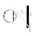
- the biometric deviceaddresses some of the problems discussed above by directing bright visible light at the eye at an angle to its line of sight. In certain embodiments, this angle, theta, may be very steep. A significant or substantial amount of the visible light may not be directed through the pupil onto sensitive parts of the retinal surface. The visible light can reach a surface of an iris and illuminate the iris. Using this method, bright visible illumination can be provided without causing discomfort to the user.
- a biometric systemcan provide a bright light from a small point source, of an intensity high enough to overcome much of visible ambient light incident on and/or reflected off the eye.
- a light sourcesuch as a bright LED
- a light sourcemay be mounted at the edge of the device in order to increase or maximize the incident light's angle with the eye's line of sight.
- an angle, thetaat or greater than 30 degrees is used.
- the anglemay be measured between a) a line between the user/eye and the light source, and b) a line perpendicular to the plane of the iris.
- (b)may be represented by a line of sight of the eye.
- iris recognitionis typically performed using infra-red light.
- sensors in camera phones or other mobile devicesare typically not configured for iris biometric acquisition. These sensors may instead be optimized or configured to acquire imagery under visible light.
- IR-cut filtersmay be applied to some of these sensors to remove IR “artifacts” from the images.
- biometric acquisition featuresin these and other existing devices, it may be costly to retrofit, reconfigure or incorporate these devices, e.g., with IR light sources and/or IR sensors.
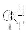
- FIG. 2Adepicts a schematic layout of an eye in which visible illumination or light is directed towards the eye.
- a biometric systemwhich may include a biometric device or apparatus, can provide the visible illumination.
- a primary cone of influence resulting from the incident visible illuminationsubtends a wide angle across the surface of the retina, and can intersect or overlap with the fovea of the eye.
- the primary cone of influencemay include light dispersion, refraction and/or diffusion resulting from the transmission of light through the pupil and other parts of the eye, which may result from the shape and/or refractive index of certain portions of the eye.
- bioeffectsinclude one or more of: a blink reflex which is an involuntary closure of the eyelids to prevent further discomfort, an after-image or distortion in the user's vision, and a perception of glare, all of which cause discomfort to the eye.
- a blink reflexwhich is an involuntary closure of the eyelids to prevent further discomfort
- an after-image or distortion in the user's visionand a perception of glare, all of which cause discomfort to the eye.
- the ANSI Z136.1 standard fbr laser LEDsbases the discomfort blink reflex maximum permissible exposure on a 0.25 second exposure, after which the subject is expected to blink. This yields a maximum permissible exposure of about 2.6 mW/cm ⁇ 2.
- After-image discomfortcan occur at a lower level of about 0.1 mW/cm ⁇ 2, and glare discomfort may occur at 5 uW/cm ⁇ 2.
- the ICNIRP Guidelines for Exposure of the Eye to Optical Radiation from Optical Instrumentsspecifies safety exposure limits for visible illumination.
- Various embodiments of the biometric systems disclosed hereinare designed and/or configured to avoid these bioeffects and/or address the safety exposure limits.
- the biometric systems disclosed hereinmay be designed and/or configured to use illumination levels that exceed the illumination levels of other visible or ambient light incident on the cornea, in order to acquire imagery of the iris uncontaminated by ambient reflections.
- visible light intended for illuminating an irismay have to compete with other ambient visible illumination present from the environment.
- the ambient visible illuminationcan cause contaminating artifacts or reflections off the cornea (and/or any other surface of the eye) from surrounding objects.
- These surrounding objectscan include any reflecting object or light source.
- the biometric systemwhich may include any device or apparatus, may address such competing illumination by increasing the magnitude or intensity of visible illumination that is incident on the iris to illuminate the iris for biometric purposes.
- the biometric systemmay provide a strong or bright visible illuminator for purposes of biometric acquisition, and may place the illuminator close to the eye, to drown out or overwhelm other ambient effects.
- the visible illuminatorcan dominate the photons incident on the iris as well as the cornea of the eye. The effect or influence of contaminating illumination from surrounding objects can therefore be minimized or reduced.
- FIG. 2Bdepicts one embodiment of a method for providing visible illumination to an iris for biometric acquisition.
- the biometric systemmay be configured to provide or direct visible illumination or light at a significant angle theta, for example greater than 30 degrees, towards one side of the eye. This may serve at least two main purposes. First, due to the increased angle theta, fewer photons may be transmitted through the pupil. The resulting primary cone of influence of illumination may be smaller than in the case when illumination is incident to the eye/pupil at a smaller angle. Second, the primary cone of influence may be positioned or directed away from the fovea, e.g., towards the end of the retinal surface thereby reducing the perception of brightness, and any discomfort, by the user.
- the biometric systemmay position a visible light source or illuminator such that the light source is substantially offset horizontally from the center of an eye, at the opposite side to the nose's position relative to the eye.
- the illumination that reaches the irismay be substantially free from obstruction from facial features.
- the biometric systemcan reduce or prevent shadows and blockages from eyebrows and top eyelashes, the nose and/or from bottom eyelashes. Such shadows can reduce illumination reaching the eye or iris, and may cause uneven or distorted illumination of the iris.
- such shadows or blockagesmay contaminate an acquired image of the iris with unwanted texture and/or artifacts.
- the biometric systemmay be configured to constrict an iris or constrict pupil for the purpose of increasing the area of the iris that is visible for biometric capture and identification.
- the biometric systemmay want to constrict the iris and/or the pupil (e.g., to reduce the size of the pupil and/or increase the surface area of the iris) to reduce the number of photons that can pass through the pupil, which may ultimately cause discomfort if the photon reaches a light-sensitive portion of the retina in sufficient numbers.
- the biometric systemcan constrict the iris or pupil by using a visible, low-intensity illuminator or light source (such as the screen of a mobile device) positioned in front of the user.
- the low-intensity illuminator or light sourcemay be sufficiently comfortable to the eye, for example, when the iris or pupil is constricted.
- the low-intensity illuminator or light sourceis activated at an appropriate time before or during biometric acquisition, so that the iris/pupil can react to the low-intensity illuminator or light source.
- the light sourceprovides visible light that is non-isotropic or anisotropic. Such light may be directional in nature, instead of being diffused.
- the visible light source or illuminator for illuminating the irismay comprise a point light source.
- the light sourcemay produce a light beam pattern (e.g., conical or tear-drop-shaped pattern) having a full width half brightness (FWHB) of 90, 40, 20, 10, 4 degrees for example.
- FWHBfull width half brightness
- the point light sourcemay be of sufficient intensity to provide light that illuminates the iris for proper biometric acquisition.
- Illumination sourcesmay have a non-isotropic beam pattern, such that the maximal intensity is projected at 0 degrees from the device, and the intensity diminishes continuously as it deviates away from the 0-degree direction of projection.
- the rate of reduction in intensityis typically characterized by a full-width half brightness (FWHB) value, which is the beam-width in degrees at which the intensity is half the brightness of the maximal intensity at zero degrees.
- FWHBfull-width half brightness
- sensitivity of the eyeis generally logarithmic to light intensity. As such, even at a large angle (e.g., deviating from the 0-degree projection direction), where the illumination intensity may be only 10% of the maximal illumination for example, this level of brightness may still be sufficient to cause discomfort to the eye if the maximal illumination is above a level sufficient to cause discomfort to the eye. For example, as discussed elsewhere in the specification, widely varying intensities (e.g. 2.6 mW/cm2 and 0.1 mW/cm ⁇ 2) can each cause discomfort.
- One embodiment for providing this shaping or truncationis to position the visible light source or illuminator for illuminating the iris within a light channel that is opaque to visible light (e.g., narrow physical channel), so that a narrow light beam may be formed exiting the light channel.
- a light channelthat is opaque to visible light (e.g., narrow physical channel)
- the beam pattern from the light sourceis truncated rather than diminished at larger illumination angles with respect to (e.g., the zero degree projection direction of) the light source.
- the geometry of the channel width and the depth of the LED in the channelmay dictate the angle above which the illumination beam pattern is truncated or shaped.
- the biometric devicemay direct the light beam towards an eye, in various ways as discussed herein (e.g., from a non-nasal side, angled at least 30 degrees, etc).
- the biometric systemuses a directional illumination or light source and directs the visible light at the preferred angle theta.
- the visible light source or illuminationmay be hardly visible to the user due to the methods described above for shaping or truncating the conical beam pattern of light from the light source.
- the illuminationcould cause discomfort to the eye while at further distances due to a smaller incident angle theta.
- the light beammay be virtually undetectable by the user as the biometric device moves closer into or further away from an optimal position for iris illumination.
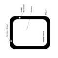
- the visible illuminator or light sourcemay be located, positioned or incorporated on one side of a mobile device, for illuminating an iris for biometric capture.
- the mobile devicemay include or house a camera or sensor that can be used for biometric capture.
- the visible light sourcemay be located far from the camera/sensor, so that the angle theta between light from the illuminator incident on an eye, and the line of sight of the eye positioned in front of the camera, can be within an suitable or desired operating range (e.g., more than 30 degrees) for biometric acquisition.
- the camera/sensor and the visible illuminatormay be located at opposite sides or ends of the biometric device.
- the visible illuminator or light sourcemay be positioned or mounted on a frame or device worn by the user.
- the light sourcemay be mounted on one or both frames of glasses that a user may wear or is requested to wear (e.g., for biometric capture).
- the light sourcemay be positioned to the side of an eye, as described above in connection with FIG. 3 .
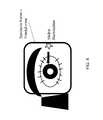
- FIG. 9depicts one embodiment of a top view of a frame worn or positioned over the eye.
- the visible light sourcemay be positioned or oriented so as to direct visible light at the eye for biometric capture of iris imagery.
- the visible light sourcemay be angled and/or positioned according to any of the ways described above in connection with FIGS. 2B through 6 .
- the visible illuminatormay incorporate a photodiode that is sensitive to infra-red illumination.
- An external infra-red illuminatormay be used to control the visible illuminator (e.g., on, off, intensity level).
- Such a setupmay reduce the amount of, or any requirement for control wires and/or switches on the frame hosting the visible light source that is worn over the eye, face or head of the subject.
- any other method of remote or wireless controlmay be used, such as the use of Bluetooth wireless communications.
- the methodincludes directing, by a light source of a biometric acquisition apparatus, visible light towards an eye at or greater than a first angle from a line of sight of the eye, to illuminate a surface of the iris ( 103 ).
- the visible lightmay have an intensity level which would cause discomfort to the eye if directed at a second angle that is less than the first angle.
- the visible lightmay also have an intensity level that exceeds the intensity level of other visible or ambient light incident on the cornea or eye.
- the visible lightilluminates substantially the whole iris of the individual ( 105 ).
- a sensor of the biometric acquisition apparatusacquires iris biometric data from the illuminated iris ( 107 ).
- a light source of a biometric acquisition apparatusdirects visible light towards an eye at or greater than a first angle from a line of sight of the eye, to illuminate the iris.
- the light sourcemay comprise a visible light source for any portion of the visible light spectrum.
- the light sourceprovides or produces infra-red light in addition to visible light.
- the light sourcemay direct the visible light at an angle that avoids reaching a light-sensitive portion of the eye's retina.
- the light sourcemay direct visible light at an angle of about 30 degree or more from the line of sight of the eye.
- the light sourcemay direct visible light at or greater than a first angle from a line of sight of the eye such that the visible light has an intensity level which would cause discomfort to the eye if directed to the eye at a second angle that is less than the first angle.
- the light sourcemay direct visible light at an angle of at least theta degrees from a line of sight of the eye, where theta is determined such that the visible light does not reach a light-sensitive portion of the retina (e.g. fovea, parafovea and/or perifovea), or cause discomfort to the eye.
- the light sourcemay direct visible light at an angle of at least theta degrees from a line of sight of the eye, where theta is determined such that a primary cone of influence of the visible light does not reach a light-sensitive portion of the retina.
- thetamay be 22 degrees, 38 degrees, 45 degrees, 70 degrees, 90 degrees, or some other value.
- the light sourcemay direct visible light at the eye such that the visible light glances or makes contact with a side, edge or portion of the iris, or any other portion of the eye.
- the visible lightmay have an intensity level above that which causes discomfort to the eye if the visible light reaches a light-sensitive part of the eye's retina.
- the incident lightmay be angled such that the visible light (e.g., including the primary cone of influence of the incident visible light) does not reach a light-sensitive portion of the retina.
- the light sourcemay produce and/or direct light of an intensity or brightness level above 2.6 mW/cm2, 0.1 mW/cm ⁇ 2 or 5 uW/cm ⁇ 2, depending on the application and context.
- the visible lightmay have an intensity level much higher than a level that would otherwise cause discomfort in the eye.
- the visible lightmay have an intensity level lower than 2.6 mW/cm2, 0.1 mW/cm ⁇ 2 or 5 uW/cm ⁇ 2.
- the visible lightmay have an intensity or brightness level lower than that which causes discomfort to the eye if the visible light reaches a light-sensitive part of the eye's retina.
- the light sourcemay have an intensity level that exceeds the intensity level of visible ambient reflections off the cornea.
- the light sourcemay have an intensity level that exceeds the intensity level(s) of other visible or ambient light incident on the cornea.
- the light sourcemay have an intensity level that exceeds the combined and/or average intensity level(s) of other visible or ambient light incident on the cornea or eye.
- the light sourcemay have an intensity level that exceeds the intensity level(s) of such light when reflected off the cornea.
- the light sourcemay provide light of an intensity subject to safety limits for exposure to an eye.
- the light sourcemay direct the visible light towards the eye, the visible light having an intensity level below a threshold limit for safe exposure to the eye.
- the light sourcemay provide or generate light of an intensity level necessary or adequate for illuminating an iris for biometric capture.
- the light sourcemay provide or generate light of an intensity level that exceeds the intensity level of other visible and/or ambient light as discussed above.
- the light sourcemay direct or produce strobed or intermittent light at the eye.
- the strobed or intermittent lightmay have an average intensity or brightness level that is higher or lower than a level that would otherwise cause discomfort in the eye, e.g., if the light reaches a light-sensitive part of the retina.
- the light sourcedirects visible light comprising non-isotropic illumination at or towards the eye.
- the light sourcemay comprise a point light source directing a conical illumination beam at the eye, the conical illumination beam having a FWHB of less than 90 degrees.
- the light sourcemay be a small or point light source of any shape.
- the FWHB of the sourcemay itself be of a specific angle, e.g., 90, 40, 20, 10, 4 degrees.
- the light sourcemay produce and/or direct a visible light beam of any shape or size.
- the light sourcedirects visible light comprising non-isotropic illumination at or towards the eye.
- the light sourcemay comprise a non-isotropic or anisotropic light source.
- the light sourcemay comprise an isotropic, collimated or directional light source.
- the light sourcedirects the visible light towards a non-nasal side of the eye.
- the light sourcemay direct the visible light from a non-nasal side of the eye.
- the light sourcemay be positioned at an opposite side of the nose relative to the eye.
- the position and/or direction of the visible lightmay be selected so that there is less, little, minimal or no obstruction by facial features such as eyebrows, lashes, eye-lid, cheek and/or nose.
- the light sourcedirects the visible light from a side of the eye towards the non-nasal side of the eye, and/or at an angle theta as described above.
- the position and/or direction of the visible lightmay be selected so that shadows are minimized or not created by obstructing features on the iris.
- the position and/or direction of the visible lightmay be selected so as to avoid distorted or uneven illumination of the iris.
- the light sourcemay be arranged so as to avoid illumination of the eye as the user positions the biometric apparatus/device for use, e.g., until the apparatus/device is positioned within a suitable spatial region for biometric acquisition.
- the apparatus/devicemay include a channel for shaping light from the source to produce a light beam for illuminating the iris.
- the biometric apparatusincludes a mobile device.
- the light source and the sensormay be both incorporated on the mobile device (e.g., cell phone or laptop).
- the light source and the sensormay be located at opposite sides or ends of the mobile device.
- the light source and the sensormay be separated in location to satisfy the theta angle requirements when the mobile device is positioned against an eye for biometric acquisition.
- the light sourceis mounted on a frame or device worn over the individual's eye, face or head.
- the light source and the biometric sensormay be separated in location to satisfy the theta angle requirements when the biometric apparatus (e.g., the sensor) is positioned against an eye for biometric acquisition.
- the light source on the frame or mobile devicemay be angled, positioned or oriented according to any of the configurations described herein.
- the biometric apparatusincludes a screen providing visual cues to suitably position the light source relative to the eye for the biometric acquisition.
- the screenmay include onscreen markers, bars or indicators to guide the user's eye against the sensor and/or the visible light source.
- the screenmay include onscreen markers, bars or indicators located close to the sensor.
- the biometric apparatusincludes an audio feedback module providing audio cues to suitably position the light source relative to the eye for the biometric acquisition.
- He biometric apparatusmay include one or more means, e.g., a screen, audio cues, mirror, projected light indicators, etc, for guiding a user position an eye against the sensor and/or the visible light source
- the visible lightilluminates substantially the whole iris of the individual.
- the light sourcemay be configured to produce visible light of sufficient intensity to substantially illuminate the whole iris for biometric acquisition.
- the light sourcemay be configured to produce a visible light beam (e.g., narrow light beam) of sufficient intensity to substantially illuminate the whole iris for biometric acquisition.
- the light sourcedirects a beam with a FWHB of less than 90 degrees, the visible light beam of sufficient intensity to illuminate the whole iris via light diffusion within a portion of the eye.
- the FWHB valuemay, for example, be 90, 40, 20, 10, 4 degrees.
- the intensity of the corresponding light beammay be adjusted or configured accordingly to substantially illuminate enough features of the iris for biometric acquisition.
- the light sourcemay direct visible light of sufficient intensity to illuminate striations of the iris for biometric acquisition.
- the light sourcemay direct visible light of sufficient intensity and/or at a specific angle relative to the line of sight of the eye, to illuminate enough striations and/or other features of the iris for biometric acquisition.
- the light sourcemay direct visible light of sufficient intensity that exceeds the intensity of other visible and/or ambient light as discussed above.
- the biometric apparatusincludes an illuminated screen or second visible light source for dilating the pupil.
- the biometric apparatusmay include an illuminated screen or second visible light source for dilating the iris.
- the illuminated screen or second visible light sourcemay be positioned sufficiently close to the eye to induce dilation.
- the illuminated screen or second visible light sourcemay be configured to provide sufficient brightness to induce dilation but not discomfort.
- a sensor of the biometric apparatusacquires iris biometric data from the illuminated iris.
- the biometric apparatusmay determine that the pupil or iris is dilated and ready for biometric acquisition.
- a usermay activate the biometric apparatus to acquire the biometric data, e.g., based on an indicator of the apparatus indicating that the visible illumination and/or sensor is positioned within an optimal or suitable operating range or at an optimal or suitable operating point.
- the biometric apparatusautomatically initiates biometric capture when the illumination, sensor and iris are in position or are aligned.
- the biometric apparatusturns off the visible illuminator when it detects that the visible illuminator is angled within theta degrees, such that the visible illuminator may cause discomfort to the eye if not turned off.
- systems described abovemay provide multiple ones of any or each of those components and these components may be provided on either a standalone machine or, in some embodiments, on multiple machines in a distributed system.
- the systems and methods described abovemay be implemented as a method, apparatus or article of manufacture using programming and/or engineering techniques to produce software, firmware, hardware, or any combination thereof.
- the systems and methods described abovemay be provided as one or more computer-readable programs embodied on or in one or more articles of manufacture.
- article of manufactureis intended to encompass code or logic accessible from and embedded in one or more computer-readable devices, firmware, programmable logic, memory devices (e.g., EEPROMs, ROMs, PROMs, RAMs, SRAMs, etc.), hardware (e.g., integrated circuit chip, Field Programmable Gate Array (FPGA), Application Specific Integrated Circuit (ASIC), etc.), electronic devices, a computer readable non-volatile storage unit (e.g., CD-ROM, floppy disk, hard disk drive, etc.).
- the article of manufacturemay be accessible from a file server providing access to the computer-readable programs via a network transmission line, wireless transmission media, signals propagating through space, radio waves, infrared signals, etc.
- the article of manufacturemay be a flash memory card or a magnetic tape.
- the article of manufactureincludes hardware logic as well as software or programmable code embedded in a computer readable medium that is executed by a processor.
- the computer-readable programsmay be implemented in any programming language, such as LISP, PERL, C, C++, C#, PROLOG, or in any byte code language such as JAVA.
- the software programsmay be stored on or in one or more articles of manufacture as object code.
Landscapes
- Engineering & Computer Science (AREA)
- Health & Medical Sciences (AREA)
- General Health & Medical Sciences (AREA)
- Ophthalmology & Optometry (AREA)
- Human Computer Interaction (AREA)
- Physics & Mathematics (AREA)
- General Physics & Mathematics (AREA)
- Multimedia (AREA)
- Theoretical Computer Science (AREA)
- Measurement Of The Respiration, Hearing Ability, Form, And Blood Characteristics Of Living Organisms (AREA)
- Image Input (AREA)
- Collating Specific Patterns (AREA)
Abstract
Description
Claims (19)
Priority Applications (1)
| Application Number | Priority Date | Filing Date | Title |
|---|---|---|---|
| US13/473,468US9124798B2 (en) | 2011-05-17 | 2012-05-16 | Systems and methods for illuminating an iris with visible light for biometric acquisition |
Applications Claiming Priority (2)
| Application Number | Priority Date | Filing Date | Title |
|---|---|---|---|
| US201161486962P | 2011-05-17 | 2011-05-17 | |
| US13/473,468US9124798B2 (en) | 2011-05-17 | 2012-05-16 | Systems and methods for illuminating an iris with visible light for biometric acquisition |
Publications (2)
| Publication Number | Publication Date |
|---|---|
| US20120293643A1 US20120293643A1 (en) | 2012-11-22 |
| US9124798B2true US9124798B2 (en) | 2015-09-01 |
Family
ID=47174659
Family Applications (1)
| Application Number | Title | Priority Date | Filing Date |
|---|---|---|---|
| US13/473,468Expired - Fee RelatedUS9124798B2 (en) | 2011-05-17 | 2012-05-16 | Systems and methods for illuminating an iris with visible light for biometric acquisition |
Country Status (2)
| Country | Link |
|---|---|
| US (1) | US9124798B2 (en) |
| WO (1) | WO2012158825A2 (en) |
Cited By (3)
| Publication number | Priority date | Publication date | Assignee | Title |
|---|---|---|---|---|
| US9773169B1 (en)* | 2012-11-06 | 2017-09-26 | Cross Match Technologies, Inc. | System for capturing a biometric image in high ambient light environments |
| US9916501B2 (en)* | 2016-07-22 | 2018-03-13 | Yung-Hui Li | Smart eyeglasses with iris recognition device |
| US11322171B1 (en) | 2007-12-17 | 2022-05-03 | Wai Wu | Parallel signal processing system and method |
Families Citing this family (37)
| Publication number | Priority date | Publication date | Assignee | Title |
|---|---|---|---|---|
| US8260008B2 (en) | 2005-11-11 | 2012-09-04 | Eyelock, Inc. | Methods for performing biometric recognition of a human eye and corroboration of same |
| US8364646B2 (en) | 2006-03-03 | 2013-01-29 | Eyelock, Inc. | Scalable searching of biometric databases using dynamic selection of data subsets |
| US8604901B2 (en) | 2006-06-27 | 2013-12-10 | Eyelock, Inc. | Ensuring the provenance of passengers at a transportation facility |
| US8965063B2 (en) | 2006-09-22 | 2015-02-24 | Eyelock, Inc. | Compact biometric acquisition system and method |
| WO2008042879A1 (en) | 2006-10-02 | 2008-04-10 | Global Rainmakers, Inc. | Fraud resistant biometric financial transaction system and method |
| US8953849B2 (en) | 2007-04-19 | 2015-02-10 | Eyelock, Inc. | Method and system for biometric recognition |
| WO2008131201A1 (en) | 2007-04-19 | 2008-10-30 | Global Rainmakers, Inc. | Method and system for biometric recognition |
| US8212870B2 (en) | 2007-09-01 | 2012-07-03 | Hanna Keith J | Mirror system and method for acquiring biometric data |
| US9036871B2 (en) | 2007-09-01 | 2015-05-19 | Eyelock, Inc. | Mobility identity platform |
| US9002073B2 (en) | 2007-09-01 | 2015-04-07 | Eyelock, Inc. | Mobile identity platform |
| WO2009029757A1 (en) | 2007-09-01 | 2009-03-05 | Global Rainmakers, Inc. | System and method for iris data acquisition for biometric identification |
| US9117119B2 (en) | 2007-09-01 | 2015-08-25 | Eyelock, Inc. | Mobile identity platform |
| WO2009158662A2 (en) | 2008-06-26 | 2009-12-30 | Global Rainmakers, Inc. | Method of reducing visibility of illimination while acquiring high quality imagery |
| US10043229B2 (en) | 2011-01-26 | 2018-08-07 | Eyelock Llc | Method for confirming the identity of an individual while shielding that individual's personal data |
| RU2589859C2 (en) | 2011-02-17 | 2016-07-10 | АЙЛОК ЭлЭлСи | Efficient method and system for obtaining image data of scene and iris image using one sensor |
| WO2012158825A2 (en) | 2011-05-17 | 2012-11-22 | Eyelock Inc. | Systems and methods for illuminating an iris with visible light for biometric acquisition |
| WO2014176324A1 (en)* | 2013-04-23 | 2014-10-30 | Surgilum, Llc | Eye marker device with electronic positional detection system and tip associated therewith |
| US9846311B2 (en)* | 2013-07-30 | 2017-12-19 | Jonathan Stephen Farringdon | Method and apparatus for forming a visible image in space |
| WO2016040836A1 (en)* | 2014-09-12 | 2016-03-17 | Eyelock Llc | Methods and apparatus for directing the gaze of a user in an iris recognition system |
| US10621431B2 (en)* | 2015-03-27 | 2020-04-14 | Lenovo (Singapore) Pte. Ltd. | Camera that uses light from plural light sources disposed on a device |
| US10049272B2 (en) | 2015-09-24 | 2018-08-14 | Microsoft Technology Licensing, Llc | User authentication using multiple capture techniques |
| US10445606B2 (en) | 2015-10-08 | 2019-10-15 | Microsoft Technology Licensing, Llc | Iris recognition |
| US10157312B2 (en) | 2015-10-08 | 2018-12-18 | Microsoft Technology Licensing, Llc | Iris recognition |
| KR101690646B1 (en)* | 2016-08-02 | 2016-12-28 | 아이피랩 주식회사 | Camera driving device and method for see-through displaying |
| CN107865473B (en)* | 2016-09-26 | 2019-10-25 | 华硕电脑股份有限公司 | human body characteristic distance measuring device and distance measuring method thereof |
| US20180104099A1 (en)* | 2016-10-13 | 2018-04-19 | Ronald Michael Kurtz | Digitally controlled optical system for nonpharmacologic constriction of a pupil |
| US10406352B2 (en)* | 2016-10-13 | 2019-09-10 | Ronald Michael Kurtz | System for temporary nonpharmacologic constriction of the pupil |
| US10406380B2 (en)* | 2016-10-13 | 2019-09-10 | Ronald Michael Kurtz | Method for nonpharmacologic temporary constriction of a pupil |
| US20180104506A1 (en)* | 2016-10-13 | 2018-04-19 | Ronald Michael Kurtz | Mobile platform for nonpharmacologic constriction of a pupil |
| US10925479B2 (en)* | 2016-10-13 | 2021-02-23 | Ronald Michael Kurtz | Networked system of mobile communication platforms for nonpharmacologic constriction of a pupil |
| US20180104098A1 (en)* | 2016-10-13 | 2018-04-19 | Ronald Michael Kurtz | System for nonpharmacologic long-term constriction of a pupil |
| US20180104508A1 (en)* | 2016-10-13 | 2018-04-19 | Ronald Michael Kurtz | Optical system for nonpharmacologic constriction of a pupil |
| ES2610196A1 (en)* | 2016-12-20 | 2017-04-26 | Universitat D'alacant / Universidad De Alicante | Method and biometric authentication device through the recognition of flashing (Machine-translation by Google Translate, not legally binding) |
| US10534969B2 (en)* | 2017-02-24 | 2020-01-14 | Eyelock Llc | Systems and methods for providing illumination for iris biometric acquisition |
| CN108257091B (en)* | 2018-01-16 | 2022-08-05 | 北京小米移动软件有限公司 | Imaging processing method for smart mirror and smart mirror |
| EP3846751B1 (en) | 2018-09-04 | 2024-12-18 | AMO Development, LLC | Narrow angle illumination ring for ophthalmic surgical laser system |
| US20230260481A1 (en)* | 2022-02-17 | 2023-08-17 | Lenovo (Singapore) Pte. Ltd | Device having a camera overlaid by display |
Citations (115)
| Publication number | Priority date | Publication date | Assignee | Title |
|---|---|---|---|---|
| US4641349A (en)* | 1985-02-20 | 1987-02-03 | Leonard Flom | Iris recognition system |
| US5291560A (en)* | 1991-07-15 | 1994-03-01 | Iri Scan Incorporated | Biometric personal identification system based on iris analysis |
| US5572596A (en) | 1994-09-02 | 1996-11-05 | David Sarnoff Research Center, Inc. | Automated, non-invasive iris recognition system and method |
| JPH09305765A (en) | 1996-05-15 | 1997-11-28 | Oki Electric Ind Co Ltd | Method and device for identifying iris |
| US5748238A (en) | 1992-03-12 | 1998-05-05 | Hitachi, Ltd. | Video camera |
| JPH11203478A (en) | 1998-01-07 | 1999-07-30 | Oki Electric Ind Co Ltd | Iris data acquiring device |
| US5953130A (en) | 1997-01-06 | 1999-09-14 | Cognex Corporation | Machine vision methods and apparatus for machine vision illumination of an object |
| US5999653A (en)* | 1996-01-19 | 1999-12-07 | Xerox Corporation | Fast techniques for searching images using the Hausdorff distance |
| US6055322A (en) | 1997-12-01 | 2000-04-25 | Sensor, Inc. | Method and apparatus for illuminating and imaging eyes through eyeglasses using multiple sources of illumination |
| US6062475A (en) | 1997-06-25 | 2000-05-16 | Metanetics Corporation | Portable data collection device including color imaging dataform reader assembly |
| US6088470A (en) | 1998-01-27 | 2000-07-11 | Sensar, Inc. | Method and apparatus for removal of bright or dark spots by the fusion of multiple images |
| JP2000322029A (en) | 1999-05-13 | 2000-11-24 | Nec Corp | Liquid crystal display device |
| US6152563A (en)* | 1998-02-20 | 2000-11-28 | Hutchinson; Thomas E. | Eye gaze direction tracker |
| US6246751B1 (en) | 1997-08-11 | 2001-06-12 | International Business Machines Corporation | Apparatus and methods for user identification to deny access or service to unauthorized users |
| US6247813B1 (en)* | 1999-04-09 | 2001-06-19 | Iritech, Inc. | Iris identification system and method of identifying a person through iris recognition |
| JP2002102165A (en) | 2000-09-29 | 2002-04-09 | Fuji Photo Optical Co Ltd | Endoscope device having ac lighting light source |
| US20020061178A1 (en)* | 1992-03-23 | 2002-05-23 | Roland Winston | Luminaire device |
| US20020093645A1 (en) | 2000-11-02 | 2002-07-18 | Heacock Gregory L. | System for capturing an image of the retina for identification |
| KR20020078225A (en) | 2001-04-06 | 2002-10-18 | 주식회사 큐리텍 | System and method for diagnosing remotely using iris, sclera, retina information and strorage media having program source thereof |
| US20020191388A1 (en) | 2001-06-05 | 2002-12-19 | Oleg Matveev | Device and method for vehicular invisible road illumination and imaging |
| US20030002714A1 (en)* | 2001-06-27 | 2003-01-02 | Matsushita Electric Industrial Co., Ltd. | Individual identifying apparatus |
| KR20030005113A (en) | 2002-12-04 | 2003-01-15 | 주식회사 큐리텍 | Identification system and method using iris, and media that can record computer program sources thereof |
| US20030012413A1 (en)* | 2001-07-16 | 2003-01-16 | Matsushita Electric Industrial Co., Ltd. | Iris identification apparatus and iris image pickup apparatus |
| US20030016539A1 (en)* | 2000-03-16 | 2003-01-23 | Minano Juan C. | High efficiency non-imaging optics |
| US6526160B1 (en)* | 1998-07-17 | 2003-02-25 | Media Technology Corporation | Iris information acquisition apparatus and iris identification apparatus |
| US6532298B1 (en)* | 1998-11-25 | 2003-03-11 | Iridian Technologies, Inc. | Portable authentication device and method using iris patterns |
| US6542624B1 (en)* | 1998-07-17 | 2003-04-01 | Oki Electric Industry Co., Ltd. | Iris code generating device and iris identifying system |
| US6546121B1 (en)* | 1998-03-05 | 2003-04-08 | Oki Electric Industry Co., Ltd. | Method and apparatus for identifying an iris |
| US6554705B1 (en) | 1997-08-22 | 2003-04-29 | Blake Cumbers | Passive biometric customer identification and tracking system |
| US20030081817A1 (en)* | 2001-10-31 | 2003-05-01 | Tomoyoshi Nakaigawa | Iris image pickup apparatus and iris authentication apparatus |
| KR20030034258A (en) | 2001-08-04 | 2003-05-09 | 주식회사 큐리텍 | Identification system and method using iris and retina, and media that can record computer program sources thereof |
| KR20030051970A (en) | 2001-12-20 | 2003-06-26 | 주식회사 큐리텍 | Iris registration and recognition system |
| US6591064B2 (en)* | 2001-07-24 | 2003-07-08 | Matsushita Electric Industrial Co., Ltd. | Iris pickup apparatus |
| US6614919B1 (en)* | 1998-12-25 | 2003-09-02 | Oki Electric Industry Co., Ltd. | Method of extracting iris region and individual identification device |
| US6700998B1 (en)* | 1999-04-23 | 2004-03-02 | Oki Electric Industry Co, Ltd. | Iris registration unit |
| US6714665B1 (en) | 1994-09-02 | 2004-03-30 | Sarnoff Corporation | Fully automated iris recognition system utilizing wide and narrow fields of view |
| US6785406B1 (en)* | 1999-07-19 | 2004-08-31 | Sony Corporation | Iris authentication apparatus |
| US20040170304A1 (en) | 2003-02-28 | 2004-09-02 | Haven Richard Earl | Apparatus and method for detecting pupils |
| US6819219B1 (en) | 2000-10-13 | 2004-11-16 | International Business Machines Corporation | Method for biometric-based authentication in wireless communication for access control |
| US20040240711A1 (en)* | 2003-05-27 | 2004-12-02 | Honeywell International Inc. | Face identification verification using 3 dimensional modeling |
| KR20050005336A (en) | 2003-07-01 | 2005-01-13 | 주식회사 큐리텍 | Mobile Device Dual Camera system for Iris Identification |
| US20050008201A1 (en)* | 2001-12-03 | 2005-01-13 | Yill-Byung Lee | Iris identification system and method, and storage media having program thereof |
| US6850631B1 (en)* | 1998-02-20 | 2005-02-01 | Oki Electric Industry Co., Ltd. | Photographing device, iris input device and iris image input method |
| US20050084179A1 (en) | 2003-09-04 | 2005-04-21 | Keith Hanna | Method and apparatus for performing iris recognition from an image |
| KR20050051861A (en) | 2003-11-28 | 2005-06-02 | 주식회사 큐리텍 | Multi camera system |
| US20050117172A1 (en) | 2002-01-15 | 2005-06-02 | Karsten Plamann | Microscopy imaging apparatus and method for generating an image |
| US6944318B1 (en) | 1999-01-15 | 2005-09-13 | Citicorp Development Center, Inc. | Fast matching systems and methods for personal identification |
| US6950536B2 (en) | 2002-01-25 | 2005-09-27 | Houvener Robert C | High volume mobile identity verification system and method using tiered biometric analysis |
| US6966681B2 (en) | 2003-10-29 | 2005-11-22 | Ford Global Technologies Llc | Active night vision system for vehicles employing anti-blinding scheme |
| US20050270386A1 (en)* | 2004-05-28 | 2005-12-08 | Hirofumi Saitoh | Method and apparatus for authentication utilizing iris |
| US20060028552A1 (en) | 2004-07-28 | 2006-02-09 | Manoj Aggarwal | Method and apparatus for stereo, multi-camera tracking and RF and video track fusion |
| US6999221B1 (en)* | 2003-11-17 | 2006-02-14 | Alabama A&M University | Bimorphic polymeric photomechanical actuator |
| US7007298B1 (en) | 1999-03-12 | 2006-02-28 | Fujitsu Limited | Apparatus and method for authenticating user according to biometric information |
| US7020351B1 (en) | 1999-10-08 | 2006-03-28 | Sarnoff Corporation | Method and apparatus for enhancing and indexing video and audio signals |
| KR100565959B1 (en)* | 2003-12-15 | 2006-03-30 | 학교법인연세대학교 | Imitation Iris Identification Method Using Visible Light |
| US20060073449A1 (en) | 2004-08-18 | 2006-04-06 | Rakesh Kumar | Automated trainee monitoring and performance evaluation system |
| US20060097172A1 (en)* | 2004-11-09 | 2006-05-11 | Samsung Electronics Co., Ltd. | Imaging apparatus, medium, and method using infrared rays with image discrimination |
| US20060098097A1 (en)* | 2004-09-13 | 2006-05-11 | Wach Hans B | Iris image capture devices and associated systems |
| US7047418B1 (en) | 2000-11-29 | 2006-05-16 | Applied Minds, Inc. | Imaging method and device using biometric information for operator authentication |
| US20060113386A1 (en) | 2004-12-01 | 2006-06-01 | Psc Scanning, Inc. | Illumination pulsing method for a data reader |
| US20060115130A1 (en) | 2004-11-29 | 2006-06-01 | Douglas Kozlay | Eyewear with biometrics to protect displayed data |
| US20060165266A1 (en)* | 2005-01-26 | 2006-07-27 | Honeywell International Inc. | Iris recognition system and method |
| US20060164541A1 (en) | 2005-01-27 | 2006-07-27 | Olmstead Bryan L | Rolling-reset imager with optical filter |
| US20060274918A1 (en)* | 2005-06-03 | 2006-12-07 | Sarnoff Corporation | Method and apparatus for designing iris biometric systems for use in minimally constrained settings |
| US20060279630A1 (en) | 2004-07-28 | 2006-12-14 | Manoj Aggarwal | Method and apparatus for total situational awareness and monitoring |
| US7152782B2 (en) | 2003-07-11 | 2006-12-26 | Visa International Service Association | System and method for managing electronic data transfer applications |
| US20070036397A1 (en)* | 2005-01-26 | 2007-02-15 | Honeywell International Inc. | A distance iris recognition |
| US7215491B2 (en)* | 2002-09-20 | 2007-05-08 | National Institute Of Advanced Industrial Science And Technology | Optical path switching device and method |
| US20070110285A1 (en) | 2005-11-11 | 2007-05-17 | Hanna Keith J | Apparatus and methods for detecting the presence of a human eye |
| US20070206839A1 (en) | 2006-03-03 | 2007-09-06 | Hanna Keith J | Salable searching of biometric databases using dynamic selection of data subsets |
| US7301686B2 (en)* | 2004-02-20 | 2007-11-27 | Dainichiseika Color & Chemicals Mfg. Co., Ltd. | Optically controlled optical-path-switching apparatus, and method of switching optical paths |
| US7346472B1 (en) | 2000-09-07 | 2008-03-18 | Blue Spike, Inc. | Method and device for monitoring and analyzing signals |
| US20080122578A1 (en) | 2006-06-27 | 2008-05-29 | Hoyos Hector T | Ensuring the provenance of passengers at a transportation facility |
| US20080158348A1 (en) | 2006-12-29 | 2008-07-03 | General Electric Company | Inspection apparatus having illumination assembly |
| US7398925B2 (en) | 2003-12-09 | 2008-07-15 | First Data Corporation | Systems and methods for assessing the risk of a financial transaction using biometric information |
| US20080253622A1 (en)* | 2006-09-15 | 2008-10-16 | Retica Systems, Inc. | Multimodal ocular biometric system and methods |
| US20080277601A1 (en)* | 2007-05-09 | 2008-11-13 | Honeywell International Inc. | Eye-safe near infra-red imaging illumination method and system |
| US20080291279A1 (en) | 2004-06-01 | 2008-11-27 | L-3 Communications Corporation | Method and System for Performing Video Flashlight |
| US7545962B2 (en) | 2005-12-22 | 2009-06-09 | Daon Holdings Limited | Biometric authentication system |
| US20090175506A1 (en)* | 2002-12-31 | 2009-07-09 | Polcha Andrew J | Recoverable biometric identity system and method |
| US7574021B2 (en) | 2006-09-18 | 2009-08-11 | Sarnoff Corporation | Iris recognition for a secure facility |
| JP2009193197A (en)* | 2008-02-13 | 2009-08-27 | Oki Electric Ind Co Ltd | Iris authentication method and iris authentication apparatus |
| US20090274345A1 (en) | 2006-09-22 | 2009-11-05 | Hanna Keith J | Compact Biometric Acquisition System and Method |
| WO2009158662A2 (en) | 2008-06-26 | 2009-12-30 | Global Rainmakers, Inc. | Method of reducing visibility of illimination while acquiring high quality imagery |
| US20100014720A1 (en) | 2006-10-02 | 2010-01-21 | Hoyos Hector T | Fraud Resistant Biometric Financial Transaction System and Method |
| US20100232655A1 (en) | 2007-09-01 | 2010-09-16 | Global Rainmakers, Inc. | System and method for Iris Data Acquisition for Biometric Identification |
| US20100253816A1 (en) | 2009-03-30 | 2010-10-07 | Global Rainmakers, Inc. | Biometric Camera Mount System |
| US7847688B2 (en) | 2005-12-16 | 2010-12-07 | Morpho | Method and apparatus of protecting a physical access |
| US20110002510A1 (en) | 2008-09-15 | 2011-01-06 | Global Rainmakers, Inc | Operator interface for face and iris recognition devices |
| US20110007949A1 (en) | 2005-11-11 | 2011-01-13 | Global Rainmakers, Inc. | Methods for performing biometric recognition of a human eye and corroboration of same |
| US7925059B2 (en) | 2005-06-03 | 2011-04-12 | Sri International | Method and apparatus for iris biometric systems for use in an entryway |
| US20110119111A1 (en) | 2007-05-18 | 2011-05-19 | Global Rainmakers, Inc. | Measuring Effectiveness of Advertisements and Linking Certain Consumer Activities Including Purchases to Other Activities of the Consumer |
| US20110119141A1 (en) | 2009-11-16 | 2011-05-19 | Hoyos Corporation | Siccolla Identity Verification Architecture and Tool |
| US20110211054A1 (en) | 2007-09-01 | 2011-09-01 | Global Rainmakers, Inc. | Mirror system and method for acquiring biometric data |
| US8028896B2 (en) | 2007-12-14 | 2011-10-04 | Bank Of America Corporation | Authentication methods for use in financial transactions and information banking |
| US8090246B2 (en) | 2008-08-08 | 2012-01-03 | Honeywell International Inc. | Image acquisition system |
| US8159328B2 (en) | 2008-07-16 | 2012-04-17 | George William Luckhardt | Biometric authentication and verification |
| US20120206485A1 (en)* | 2010-02-28 | 2012-08-16 | Osterhout Group, Inc. | Ar glasses with event and sensor triggered user movement control of ar eyepiece facilities |
| US20120212597A1 (en) | 2011-02-17 | 2012-08-23 | Eyelock, Inc. | Efficient method and system for the acquisition of scene imagery and iris imagery using a single sensor |
| US20120242820A1 (en) | 2007-09-01 | 2012-09-27 | Eyelock, Inc. | Mobile identity platform |
| US20120268241A1 (en) | 2011-04-19 | 2012-10-25 | Eyelock Inc. | Biometric chain of provenance |
| US20120293643A1 (en) | 2011-05-17 | 2012-11-22 | Eyelock Inc. | Systems and methods for illuminating an iris with visible light for biometric acquisition |
| US20130051631A1 (en) | 2011-08-22 | 2013-02-28 | Eyelock Inc. | Systems and methods for capturing artifact free images |
| US8411909B1 (en) | 2012-06-26 | 2013-04-02 | Google Inc. | Facial recognition |
| US8443202B2 (en) | 2009-08-05 | 2013-05-14 | Daon Holdings Limited | Methods and systems for authenticating users |
| US8442339B2 (en) | 2006-09-21 | 2013-05-14 | Stmicroelectronics S.A. | Method and device for selecting images in a sequence of iris images received in a stream |
| US20130162799A1 (en) | 2007-09-01 | 2013-06-27 | Keith J. Hanna | Mobility identity platform |
| US20130162798A1 (en) | 2007-09-01 | 2013-06-27 | Keith J. Hanna | Mobile identity platform |
| US20130182915A1 (en) | 2007-04-19 | 2013-07-18 | Eyelock, Inc. | Method and system for biometric recognition |
| US8506112B1 (en)* | 2011-08-08 | 2013-08-13 | Quarkstar Llc | Illumination devices including multiple light emitting elements |
| US20130212655A1 (en) | 2006-10-02 | 2013-08-15 | Hector T. Hoyos | Efficient prevention fraud |
| KR20140028950A (en) | 2012-08-31 | 2014-03-10 | 주식회사 이리언스 | Iris identifying system with guide |
| KR20140039803A (en) | 2012-09-25 | 2014-04-02 | 주식회사 이리언스 | Payment system and method using iris information |
| KR20140050501A (en) | 2012-10-19 | 2014-04-29 | 주식회사 이리언스 | System and method for certificate management |
| US8719584B2 (en) | 2010-10-26 | 2014-05-06 | Bi2 Technologies, LLC | Mobile, wireless hand-held biometric capture, processing and communication system and method for biometric identification |
- 2012
- 2012-05-16WOPCT/US2012/038188patent/WO2012158825A2/enactiveApplication Filing
- 2012-05-16USUS13/473,468patent/US9124798B2/ennot_activeExpired - Fee Related
Patent Citations (157)
| Publication number | Priority date | Publication date | Assignee | Title |
|---|---|---|---|---|
| US4641349A (en)* | 1985-02-20 | 1987-02-03 | Leonard Flom | Iris recognition system |
| US5291560A (en)* | 1991-07-15 | 1994-03-01 | Iri Scan Incorporated | Biometric personal identification system based on iris analysis |
| US5748238A (en) | 1992-03-12 | 1998-05-05 | Hitachi, Ltd. | Video camera |
| US20020061178A1 (en)* | 1992-03-23 | 2002-05-23 | Roland Winston | Luminaire device |
| US5572596A (en) | 1994-09-02 | 1996-11-05 | David Sarnoff Research Center, Inc. | Automated, non-invasive iris recognition system and method |
| US5751836A (en)* | 1994-09-02 | 1998-05-12 | David Sarnoff Research Center Inc. | Automated, non-invasive iris recognition system and method |
| US6714665B1 (en) | 1994-09-02 | 2004-03-30 | Sarnoff Corporation | Fully automated iris recognition system utilizing wide and narrow fields of view |
| US5999653A (en)* | 1996-01-19 | 1999-12-07 | Xerox Corporation | Fast techniques for searching images using the Hausdorff distance |
| JPH09305765A (en) | 1996-05-15 | 1997-11-28 | Oki Electric Ind Co Ltd | Method and device for identifying iris |
| US5953130A (en) | 1997-01-06 | 1999-09-14 | Cognex Corporation | Machine vision methods and apparatus for machine vision illumination of an object |
| US6062475A (en) | 1997-06-25 | 2000-05-16 | Metanetics Corporation | Portable data collection device including color imaging dataform reader assembly |
| US6246751B1 (en) | 1997-08-11 | 2001-06-12 | International Business Machines Corporation | Apparatus and methods for user identification to deny access or service to unauthorized users |
| US6554705B1 (en) | 1997-08-22 | 2003-04-29 | Blake Cumbers | Passive biometric customer identification and tracking system |
| US6055322A (en) | 1997-12-01 | 2000-04-25 | Sensor, Inc. | Method and apparatus for illuminating and imaging eyes through eyeglasses using multiple sources of illumination |
| US6252977B1 (en) | 1997-12-01 | 2001-06-26 | Sensar, Inc. | Method and apparatus for illuminating and imaging eyes through eyeglasses using multiple sources of illumination |
| JPH11203478A (en) | 1998-01-07 | 1999-07-30 | Oki Electric Ind Co Ltd | Iris data acquiring device |
| US6088470A (en) | 1998-01-27 | 2000-07-11 | Sensar, Inc. | Method and apparatus for removal of bright or dark spots by the fusion of multiple images |
| US6152563A (en)* | 1998-02-20 | 2000-11-28 | Hutchinson; Thomas E. | Eye gaze direction tracker |
| US6850631B1 (en)* | 1998-02-20 | 2005-02-01 | Oki Electric Industry Co., Ltd. | Photographing device, iris input device and iris image input method |
| US6546121B1 (en)* | 1998-03-05 | 2003-04-08 | Oki Electric Industry Co., Ltd. | Method and apparatus for identifying an iris |
| US6526160B1 (en)* | 1998-07-17 | 2003-02-25 | Media Technology Corporation | Iris information acquisition apparatus and iris identification apparatus |
| US6542624B1 (en)* | 1998-07-17 | 2003-04-01 | Oki Electric Industry Co., Ltd. | Iris code generating device and iris identifying system |
| US6532298B1 (en)* | 1998-11-25 | 2003-03-11 | Iridian Technologies, Inc. | Portable authentication device and method using iris patterns |
| US6614919B1 (en)* | 1998-12-25 | 2003-09-02 | Oki Electric Industry Co., Ltd. | Method of extracting iris region and individual identification device |
| US6944318B1 (en) | 1999-01-15 | 2005-09-13 | Citicorp Development Center, Inc. | Fast matching systems and methods for personal identification |
| US7007298B1 (en) | 1999-03-12 | 2006-02-28 | Fujitsu Limited | Apparatus and method for authenticating user according to biometric information |
| US6247813B1 (en)* | 1999-04-09 | 2001-06-19 | Iritech, Inc. | Iris identification system and method of identifying a person through iris recognition |
| US6700998B1 (en)* | 1999-04-23 | 2004-03-02 | Oki Electric Industry Co, Ltd. | Iris registration unit |
| JP2000322029A (en) | 1999-05-13 | 2000-11-24 | Nec Corp | Liquid crystal display device |
| US6785406B1 (en)* | 1999-07-19 | 2004-08-31 | Sony Corporation | Iris authentication apparatus |
| US7020351B1 (en) | 1999-10-08 | 2006-03-28 | Sarnoff Corporation | Method and apparatus for enhancing and indexing video and audio signals |
| US20030016539A1 (en)* | 2000-03-16 | 2003-01-23 | Minano Juan C. | High efficiency non-imaging optics |
| US6639733B2 (en)* | 2000-03-16 | 2003-10-28 | Light Prescriptions Innovators, Llc. | High efficiency non-imaging optics |
| US7949494B2 (en) | 2000-09-07 | 2011-05-24 | Blue Spike, Inc. | Method and device for monitoring and analyzing signals |
| US7346472B1 (en) | 2000-09-07 | 2008-03-18 | Blue Spike, Inc. | Method and device for monitoring and analyzing signals |
| US7660700B2 (en) | 2000-09-07 | 2010-02-09 | Blue Spike, Inc. | Method and device for monitoring and analyzing signals |
| US8214175B2 (en) | 2000-09-07 | 2012-07-03 | Blue Spike, Inc. | Method and device for monitoring and analyzing signals |
| JP2002102165A (en) | 2000-09-29 | 2002-04-09 | Fuji Photo Optical Co Ltd | Endoscope device having ac lighting light source |
| US6819219B1 (en) | 2000-10-13 | 2004-11-16 | International Business Machines Corporation | Method for biometric-based authentication in wireless communication for access control |
| US20020093645A1 (en) | 2000-11-02 | 2002-07-18 | Heacock Gregory L. | System for capturing an image of the retina for identification |
| US7770019B2 (en) | 2000-11-29 | 2010-08-03 | Applied Minds, Inc. | Imaging method and device using biometric information for operator authentication |
| US7047418B1 (en) | 2000-11-29 | 2006-05-16 | Applied Minds, Inc. | Imaging method and device using biometric information for operator authentication |
| KR20020078225A (en) | 2001-04-06 | 2002-10-18 | 주식회사 큐리텍 | System and method for diagnosing remotely using iris, sclera, retina information and strorage media having program source thereof |
| US20020191388A1 (en) | 2001-06-05 | 2002-12-19 | Oleg Matveev | Device and method for vehicular invisible road illumination and imaging |
| US20030002714A1 (en)* | 2001-06-27 | 2003-01-02 | Matsushita Electric Industrial Co., Ltd. | Individual identifying apparatus |
| JP2003016434A (en) | 2001-06-27 | 2003-01-17 | Matsushita Electric Ind Co Ltd | Individual authentication device |
| US20030012413A1 (en)* | 2001-07-16 | 2003-01-16 | Matsushita Electric Industrial Co., Ltd. | Iris identification apparatus and iris image pickup apparatus |
| US6591064B2 (en)* | 2001-07-24 | 2003-07-08 | Matsushita Electric Industrial Co., Ltd. | Iris pickup apparatus |
| KR20030034258A (en) | 2001-08-04 | 2003-05-09 | 주식회사 큐리텍 | Identification system and method using iris and retina, and media that can record computer program sources thereof |
| US20030081817A1 (en)* | 2001-10-31 | 2003-05-01 | Tomoyoshi Nakaigawa | Iris image pickup apparatus and iris authentication apparatus |
| US20050008201A1 (en)* | 2001-12-03 | 2005-01-13 | Yill-Byung Lee | Iris identification system and method, and storage media having program thereof |
| KR20030051970A (en) | 2001-12-20 | 2003-06-26 | 주식회사 큐리텍 | Iris registration and recognition system |
| US20050117172A1 (en) | 2002-01-15 | 2005-06-02 | Karsten Plamann | Microscopy imaging apparatus and method for generating an image |
| US6950536B2 (en) | 2002-01-25 | 2005-09-27 | Houvener Robert C | High volume mobile identity verification system and method using tiered biometric analysis |
| US7215491B2 (en)* | 2002-09-20 | 2007-05-08 | National Institute Of Advanced Industrial Science And Technology | Optical path switching device and method |
| KR20030005113A (en) | 2002-12-04 | 2003-01-15 | 주식회사 큐리텍 | Identification system and method using iris, and media that can record computer program sources thereof |
| US20090175506A1 (en)* | 2002-12-31 | 2009-07-09 | Polcha Andrew J | Recoverable biometric identity system and method |
| US20040170304A1 (en) | 2003-02-28 | 2004-09-02 | Haven Richard Earl | Apparatus and method for detecting pupils |
| US20040240711A1 (en)* | 2003-05-27 | 2004-12-02 | Honeywell International Inc. | Face identification verification using 3 dimensional modeling |
| KR20050005336A (en) | 2003-07-01 | 2005-01-13 | 주식회사 큐리텍 | Mobile Device Dual Camera system for Iris Identification |
| US7152782B2 (en) | 2003-07-11 | 2006-12-26 | Visa International Service Association | System and method for managing electronic data transfer applications |
| US20050084179A1 (en) | 2003-09-04 | 2005-04-21 | Keith Hanna | Method and apparatus for performing iris recognition from an image |
| US6966681B2 (en) | 2003-10-29 | 2005-11-22 | Ford Global Technologies Llc | Active night vision system for vehicles employing anti-blinding scheme |
| US6999221B1 (en)* | 2003-11-17 | 2006-02-14 | Alabama A&M University | Bimorphic polymeric photomechanical actuator |
| KR20050051861A (en) | 2003-11-28 | 2005-06-02 | 주식회사 큐리텍 | Multi camera system |
| US7398925B2 (en) | 2003-12-09 | 2008-07-15 | First Data Corporation | Systems and methods for assessing the risk of a financial transaction using biometric information |
| KR100565959B1 (en)* | 2003-12-15 | 2006-03-30 | 학교법인연세대학교 | Imitation Iris Identification Method Using Visible Light |
| US7301686B2 (en)* | 2004-02-20 | 2007-11-27 | Dainichiseika Color & Chemicals Mfg. Co., Ltd. | Optically controlled optical-path-switching apparatus, and method of switching optical paths |
| US20050270386A1 (en)* | 2004-05-28 | 2005-12-08 | Hirofumi Saitoh | Method and apparatus for authentication utilizing iris |
| US20080291279A1 (en) | 2004-06-01 | 2008-11-27 | L-3 Communications Corporation | Method and System for Performing Video Flashlight |
| US20060279630A1 (en) | 2004-07-28 | 2006-12-14 | Manoj Aggarwal | Method and apparatus for total situational awareness and monitoring |
| US7929017B2 (en) | 2004-07-28 | 2011-04-19 | Sri International | Method and apparatus for stereo, multi-camera tracking and RF and video track fusion |
| US8289390B2 (en) | 2004-07-28 | 2012-10-16 | Sri International | Method and apparatus for total situational awareness and monitoring |
| US20060028552A1 (en) | 2004-07-28 | 2006-02-09 | Manoj Aggarwal | Method and apparatus for stereo, multi-camera tracking and RF and video track fusion |
| US7949295B2 (en) | 2004-08-18 | 2011-05-24 | Sri International | Automated trainee monitoring and performance evaluation system |
| US20060073449A1 (en) | 2004-08-18 | 2006-04-06 | Rakesh Kumar | Automated trainee monitoring and performance evaluation system |
| US20060098097A1 (en)* | 2004-09-13 | 2006-05-11 | Wach Hans B | Iris image capture devices and associated systems |
| US20060097172A1 (en)* | 2004-11-09 | 2006-05-11 | Samsung Electronics Co., Ltd. | Imaging apparatus, medium, and method using infrared rays with image discrimination |
| US20060115130A1 (en) | 2004-11-29 | 2006-06-01 | Douglas Kozlay | Eyewear with biometrics to protect displayed data |
| US20060113386A1 (en) | 2004-12-01 | 2006-06-01 | Psc Scanning, Inc. | Illumination pulsing method for a data reader |
| US20060165266A1 (en)* | 2005-01-26 | 2006-07-27 | Honeywell International Inc. | Iris recognition system and method |
| US20070036397A1 (en)* | 2005-01-26 | 2007-02-15 | Honeywell International Inc. | A distance iris recognition |
| US20060164541A1 (en) | 2005-01-27 | 2006-07-27 | Olmstead Bryan L | Rolling-reset imager with optical filter |
| US7925059B2 (en) | 2005-06-03 | 2011-04-12 | Sri International | Method and apparatus for iris biometric systems for use in an entryway |
| US20060274918A1 (en)* | 2005-06-03 | 2006-12-07 | Sarnoff Corporation | Method and apparatus for designing iris biometric systems for use in minimally constrained settings |
| US20110007949A1 (en) | 2005-11-11 | 2011-01-13 | Global Rainmakers, Inc. | Methods for performing biometric recognition of a human eye and corroboration of same |
| US8260008B2 (en) | 2005-11-11 | 2012-09-04 | Eyelock, Inc. | Methods for performing biometric recognition of a human eye and corroboration of same |
| US20140072183A1 (en) | 2005-11-11 | 2014-03-13 | Eyelock, Inc. | Methods for performing biometric recognition of a human eye and corroboration of same |
| US20120300052A1 (en) | 2005-11-11 | 2012-11-29 | Eyelock Inc. | Methods for performing biometric recognition of a human eye and corroboration of same |
| US20130294659A1 (en) | 2005-11-11 | 2013-11-07 | Keith J. Hanna | Methods for performing biometric recognition of a human eye and corroboration of same |
| US20130194408A1 (en) | 2005-11-11 | 2013-08-01 | Keith J. Hanna | Methods for performing biometric recognition of a human eye and corroboration of same |
| US20120300990A1 (en) | 2005-11-11 | 2012-11-29 | Eyelock Inc. | Methods for performing biometric recognition of a human eye and corroboration of same |
| US7801335B2 (en) | 2005-11-11 | 2010-09-21 | Global Rainmakers Inc. | Apparatus and methods for detecting the presence of a human eye |
| US20070110285A1 (en) | 2005-11-11 | 2007-05-17 | Hanna Keith J | Apparatus and methods for detecting the presence of a human eye |
| US7847688B2 (en) | 2005-12-16 | 2010-12-07 | Morpho | Method and apparatus of protecting a physical access |
| US7545962B2 (en) | 2005-12-22 | 2009-06-09 | Daon Holdings Limited | Biometric authentication system |
| US20130110859A1 (en) | 2006-03-03 | 2013-05-02 | Eyelock, Inc. | Scalable searching of biometric databases using dynamic selection of data subsets |
| US20070206839A1 (en) | 2006-03-03 | 2007-09-06 | Hanna Keith J | Salable searching of biometric databases using dynamic selection of data subsets |
| US8364646B2 (en) | 2006-03-03 | 2013-01-29 | Eyelock, Inc. | Scalable searching of biometric databases using dynamic selection of data subsets |
| US8604901B2 (en) | 2006-06-27 | 2013-12-10 | Eyelock, Inc. | Ensuring the provenance of passengers at a transportation facility |
| US20080122578A1 (en) | 2006-06-27 | 2008-05-29 | Hoyos Hector T | Ensuring the provenance of passengers at a transportation facility |
| US20080253622A1 (en)* | 2006-09-15 | 2008-10-16 | Retica Systems, Inc. | Multimodal ocular biometric system and methods |
| US7574021B2 (en) | 2006-09-18 | 2009-08-11 | Sarnoff Corporation | Iris recognition for a secure facility |
| US8442339B2 (en) | 2006-09-21 | 2013-05-14 | Stmicroelectronics S.A. | Method and device for selecting images in a sequence of iris images received in a stream |
| US20140064574A1 (en) | 2006-09-22 | 2014-03-06 | Eyelock. Inc. | Compact biometric acquisition system and method |
| US20090274345A1 (en) | 2006-09-22 | 2009-11-05 | Hanna Keith J | Compact Biometric Acquisition System and Method |
| US20120328164A1 (en) | 2006-10-02 | 2012-12-27 | Eyelock Inc. | Fraud resistant biometric financial transaction system and method |
| US8280120B2 (en) | 2006-10-02 | 2012-10-02 | Eyelock Inc. | Fraud resistant biometric financial transaction system and method |
| US20130212655A1 (en) | 2006-10-02 | 2013-08-15 | Hector T. Hoyos | Efficient prevention fraud |
| US20100014720A1 (en) | 2006-10-02 | 2010-01-21 | Hoyos Hector T | Fraud Resistant Biometric Financial Transaction System and Method |
| US20130182913A1 (en) | 2006-10-02 | 2013-07-18 | Eyelock Inc. | Fraud resistant biometric financial transaction system and method |
| US20120321141A1 (en) | 2006-10-02 | 2012-12-20 | Eyelock Inc. | Fraud resistant biometric financial transaction system and method |
| US20080158348A1 (en) | 2006-12-29 | 2008-07-03 | General Electric Company | Inspection apparatus having illumination assembly |
| US20130182915A1 (en) | 2007-04-19 | 2013-07-18 | Eyelock, Inc. | Method and system for biometric recognition |
| US20080277601A1 (en)* | 2007-05-09 | 2008-11-13 | Honeywell International Inc. | Eye-safe near infra-red imaging illumination method and system |
| US20110119111A1 (en) | 2007-05-18 | 2011-05-19 | Global Rainmakers, Inc. | Measuring Effectiveness of Advertisements and Linking Certain Consumer Activities Including Purchases to Other Activities of the Consumer |
| US20120239458A9 (en) | 2007-05-18 | 2012-09-20 | Global Rainmakers, Inc. | Measuring Effectiveness of Advertisements and Linking Certain Consumer Activities Including Purchases to Other Activities of the Consumer |
| US20130182093A1 (en) | 2007-09-01 | 2013-07-18 | Keith J. Hanna | System and method for iris data acquisition for biometric identification |
| US8212870B2 (en) | 2007-09-01 | 2012-07-03 | Hanna Keith J | Mirror system and method for acquiring biometric data |
| US20120243749A1 (en) | 2007-09-01 | 2012-09-27 | Eyelock, Inc. | Mirror system and method for acquiring biometric data |
| US20120242821A1 (en) | 2007-09-01 | 2012-09-27 | Eyelock, Inc. | Mirror system and method for acquiring biometric data |
| US20110211054A1 (en) | 2007-09-01 | 2011-09-01 | Global Rainmakers, Inc. | Mirror system and method for acquiring biometric data |
| US8553948B2 (en) | 2007-09-01 | 2013-10-08 | Eyelock, Inc. | System and method for iris data acquisition for biometric identification |
| US20130182095A1 (en) | 2007-09-01 | 2013-07-18 | Keith J. Hanna | System and method for iris data acquisition for biometric identification |
| US20130182094A1 (en) | 2007-09-01 | 2013-07-18 | Keith J. Hanna | System and method for iris data acquisition for biometric identification |
| US20120127295A9 (en) | 2007-09-01 | 2012-05-24 | Global Rainmakers, Inc. | Mirror system and method for acquiring biometric data |
| US20130162798A1 (en) | 2007-09-01 | 2013-06-27 | Keith J. Hanna | Mobile identity platform |
| US20100232655A1 (en) | 2007-09-01 | 2010-09-16 | Global Rainmakers, Inc. | System and method for Iris Data Acquisition for Biometric Identification |
| US20130162799A1 (en) | 2007-09-01 | 2013-06-27 | Keith J. Hanna | Mobility identity platform |
| US20120242820A1 (en) | 2007-09-01 | 2012-09-27 | Eyelock, Inc. | Mobile identity platform |
| US8028896B2 (en) | 2007-12-14 | 2011-10-04 | Bank Of America Corporation | Authentication methods for use in financial transactions and information banking |
| US8181858B2 (en) | 2007-12-14 | 2012-05-22 | Bank Of America Corporation | Information banking |
| JP2009193197A (en)* | 2008-02-13 | 2009-08-27 | Oki Electric Ind Co Ltd | Iris authentication method and iris authentication apparatus |
| WO2009158662A2 (en) | 2008-06-26 | 2009-12-30 | Global Rainmakers, Inc. | Method of reducing visibility of illimination while acquiring high quality imagery |
| US20120187838A1 (en) | 2008-06-26 | 2012-07-26 | Global Rainmakers, Inc. | Method of Reducing Visibility of Pulsed Illumination While Acquiring High Quality Imagery |
| US8159328B2 (en) | 2008-07-16 | 2012-04-17 | George William Luckhardt | Biometric authentication and verification |
| US8090246B2 (en) | 2008-08-08 | 2012-01-03 | Honeywell International Inc. | Image acquisition system |
| US8306279B2 (en) | 2008-09-15 | 2012-11-06 | Eyelock, Inc. | Operator interface for face and iris recognition devices |
| US20110002510A1 (en) | 2008-09-15 | 2011-01-06 | Global Rainmakers, Inc | Operator interface for face and iris recognition devices |
| US20100253816A1 (en) | 2009-03-30 | 2010-10-07 | Global Rainmakers, Inc. | Biometric Camera Mount System |
| US8195044B2 (en) | 2009-03-30 | 2012-06-05 | Eyelock Inc. | Biometric camera mount system |
| US20120219279A1 (en) | 2009-03-30 | 2012-08-30 | Eyelock, Inc. | Biometric camera mount system |
| US8606097B2 (en) | 2009-03-30 | 2013-12-10 | Eyelock, Inc. | Biometric camera mount system |
| US8443202B2 (en) | 2009-08-05 | 2013-05-14 | Daon Holdings Limited | Methods and systems for authenticating users |
| US20110119141A1 (en) | 2009-11-16 | 2011-05-19 | Hoyos Corporation | Siccolla Identity Verification Architecture and Tool |
| US20120206485A1 (en)* | 2010-02-28 | 2012-08-16 | Osterhout Group, Inc. | Ar glasses with event and sensor triggered user movement control of ar eyepiece facilities |
| US8719584B2 (en) | 2010-10-26 | 2014-05-06 | Bi2 Technologies, LLC | Mobile, wireless hand-held biometric capture, processing and communication system and method for biometric identification |
| US20120212597A1 (en) | 2011-02-17 | 2012-08-23 | Eyelock, Inc. | Efficient method and system for the acquisition of scene imagery and iris imagery using a single sensor |
| US20120268241A1 (en) | 2011-04-19 | 2012-10-25 | Eyelock Inc. | Biometric chain of provenance |
| WO2012158825A2 (en) | 2011-05-17 | 2012-11-22 | Eyelock Inc. | Systems and methods for illuminating an iris with visible light for biometric acquisition |
| US20120293643A1 (en) | 2011-05-17 | 2012-11-22 | Eyelock Inc. | Systems and methods for illuminating an iris with visible light for biometric acquisition |
| US8506112B1 (en)* | 2011-08-08 | 2013-08-13 | Quarkstar Llc | Illumination devices including multiple light emitting elements |
| US20130051631A1 (en) | 2011-08-22 | 2013-02-28 | Eyelock Inc. | Systems and methods for capturing artifact free images |
| US8411909B1 (en) | 2012-06-26 | 2013-04-02 | Google Inc. | Facial recognition |
| KR20140028950A (en) | 2012-08-31 | 2014-03-10 | 주식회사 이리언스 | Iris identifying system with guide |
| KR20140039803A (en) | 2012-09-25 | 2014-04-02 | 주식회사 이리언스 | Payment system and method using iris information |
| KR20140050501A (en) | 2012-10-19 | 2014-04-29 | 주식회사 이리언스 | System and method for certificate management |
Non-Patent Citations (13)
| Title |
|---|
| Chang et al, Isotropic image in structured illumination microscopy patterned with a spatial light modulator, 2009.* |
| Daugman et al, How Iris Recognition Works, 2004.* |
| Daugman, John "How Iris Recognition Works," IEEE Transaction on Circuits and Systems for Video Technology, vol. 14, No. 1, pp. 21-30 (Jan. 2004) (10 pages). |
| International Preliminary Report on Patentability in PCT/US2009/048935 dated Jan. 5, 2011 (4 pages). |
| International Preliminary Report on Patentability in PCT/US2012/038188 dated Nov. 19, 2013 (6 pages). |
| International Search Report in PCT/US2009/048935 mailed Feb. 9, 2010 (3 pages). |
| International Search Report in PCT/US2012/038188 mailed Jan. 22, 2013 (3 pages). |
| JP2009193197MT, the English Translations could be generated from the JPO web sites, Aug. 2009.* |
| KR100565959MT, the English Traslations could be generated from the web sites, Feb. 2006.* |
| Office Action U.S. Appl. No. 13/055,943, filed Mar. 4, 2014 (19 pages). |
| Office Action U.S. Appl. No. 13/055,943, filed May 16, 2013 (21 pages). |
| Written Opinion of the International Searching Authority in PCT/US2009/048935 mailed Feb. 9, 2010 (3 pages). |
| Written Opinion of the International Searching Authority in PCT/US2012/038188 mailed Jan. 22, 2013 (5 pages). |
Cited By (3)
| Publication number | Priority date | Publication date | Assignee | Title |
|---|---|---|---|---|
| US11322171B1 (en) | 2007-12-17 | 2022-05-03 | Wai Wu | Parallel signal processing system and method |
| US9773169B1 (en)* | 2012-11-06 | 2017-09-26 | Cross Match Technologies, Inc. | System for capturing a biometric image in high ambient light environments |
| US9916501B2 (en)* | 2016-07-22 | 2018-03-13 | Yung-Hui Li | Smart eyeglasses with iris recognition device |
Also Published As
| Publication number | Publication date |
|---|---|
| WO2012158825A2 (en) | 2012-11-22 |
| WO2012158825A3 (en) | 2013-03-21 |
| US20120293643A1 (en) | 2012-11-22 |
Similar Documents
| Publication | Publication Date | Title |
|---|---|---|
| US9124798B2 (en) | Systems and methods for illuminating an iris with visible light for biometric acquisition | |
| US20160026864A1 (en) | Systems and methods for capturing artifact free images | |
| CN115167723B (en) | Wearable devices capable of eye tracking | |
| US9940516B2 (en) | Mobile identity platform | |
| KR102670780B1 (en) | Technology to control visual correction of wearable computing devices | |
| US10416725B2 (en) | Wearable device having a display, lens, illuminator, and image sensor | |
| US9036871B2 (en) | Mobility identity platform | |
| CN109471523A (en) | Eye tracking using eye center position | |
| RU2672502C1 (en) | Device and method for forming cornea image | |
| JP2018514882A (en) | Tilt-shift iris imaging | |
| EP4217918B1 (en) | Flexible illumination for imaging systems | |
| CN116529786A (en) | Multi-camera biometric imaging system | |
| CN116583885A (en) | Posture Optimization in Biometric Authentication Systems | |
| EP4189527A1 (en) | Adjusting image content to improve user experience | |
| KR20140050603A (en) | Mobile identity platform | |
| US20180032814A1 (en) | Methods and apparatus for directing the gaze of a user in an iris recognition system | |
| CN116472564A (en) | Automatically selecting biometric based on quality of acquired image | |
| US20240212291A1 (en) | Attention control in multi-user environments | |
| US20230359273A1 (en) | Retinal reflection tracking for gaze alignment | |
| US12073018B2 (en) | Multiple gaze dependent illumination sources for retinal eye tracking | |
| US20250181155A1 (en) | Camera-less eye tracking system | |
| US20230309824A1 (en) | Accommodation tracking based on retinal-imaging | |
| WO2022066478A1 (en) | Glint analysis using multi-zone lens |
Legal Events
| Date | Code | Title | Description |
|---|---|---|---|
| AS | Assignment | Owner name:EYELOCK INC., PUERTO RICO Free format text:ASSIGNMENT OF ASSIGNORS INTEREST;ASSIGNOR:HANNA, KEITH J.;REEL/FRAME:031598/0747 Effective date:20120516 | |
| STCF | Information on status: patent grant | Free format text:PATENTED CASE | |
| AS | Assignment | Owner name:EYELOCK LLC, NEW YORK Free format text:ASSIGNMENT OF ASSIGNORS INTEREST;ASSIGNOR:EYELOCK, INC.;REEL/FRAME:036527/0651 Effective date:20150901 | |
| AS | Assignment | Owner name:VOXX INTERNATIONAL CORPORATION, NEW YORK Free format text:SECURITY INTEREST;ASSIGNOR:EYELOCK LLC;REEL/FRAME:036540/0954 Effective date:20150901 | |
| FEPP | Fee payment procedure | Free format text:ENTITY STATUS SET TO UNDISCOUNTED (ORIGINAL EVENT CODE: BIG.); ENTITY STATUS OF PATENT OWNER: LARGE ENTITY | |
| FEPP | Fee payment procedure | Free format text:MAINTENANCE FEE REMINDER MAILED (ORIGINAL EVENT CODE: REM.); ENTITY STATUS OF PATENT OWNER: LARGE ENTITY | |
| LAPS | Lapse for failure to pay maintenance fees | Free format text:PATENT EXPIRED FOR FAILURE TO PAY MAINTENANCE FEES (ORIGINAL EVENT CODE: EXP.); ENTITY STATUS OF PATENT OWNER: LARGE ENTITY | |
| STCH | Information on status: patent discontinuation | Free format text:PATENT EXPIRED DUE TO NONPAYMENT OF MAINTENANCE FEES UNDER 37 CFR 1.362 | |
| FP | Lapsed due to failure to pay maintenance fee | Effective date:20190901 |