US9123323B2 - Method and structure for inducing acoustic signals and attenuating acoustic signals - Google Patents
Method and structure for inducing acoustic signals and attenuating acoustic signalsDownload PDFInfo
- Publication number
- US9123323B2 US9123323B2US13/154,429US201113154429AUS9123323B2US 9123323 B2US9123323 B2US 9123323B2US 201113154429 AUS201113154429 AUS 201113154429AUS 9123323 B2US9123323 B2US 9123323B2
- Authority
- US
- United States
- Prior art keywords
- field
- generator
- magnetic field
- responsive fluid
- earpiece
- Prior art date
- Legal status (The legal status is an assumption and is not a legal conclusion. Google has not performed a legal analysis and makes no representation as to the accuracy of the status listed.)
- Active - Reinstated, expires
Links
Images


Classifications
- H—ELECTRICITY
- H04—ELECTRIC COMMUNICATION TECHNIQUE
- H04R—LOUDSPEAKERS, MICROPHONES, GRAMOPHONE PICK-UPS OR LIKE ACOUSTIC ELECTROMECHANICAL TRANSDUCERS; DEAF-AID SETS; PUBLIC ADDRESS SYSTEMS
- H04R9/00—Transducers of moving-coil, moving-strip, or moving-wire type
- H04R9/02—Details
- H04R9/025—Magnetic circuit
- H04R9/027—Air gaps using a magnetic fluid
- G—PHYSICS
- G10—MUSICAL INSTRUMENTS; ACOUSTICS
- G10K—SOUND-PRODUCING DEVICES; METHODS OR DEVICES FOR PROTECTING AGAINST, OR FOR DAMPING, NOISE OR OTHER ACOUSTIC WAVES IN GENERAL; ACOUSTICS NOT OTHERWISE PROVIDED FOR
- G10K11/00—Methods or devices for transmitting, conducting or directing sound in general; Methods or devices for protecting against, or for damping, noise or other acoustic waves in general
- G10K11/16—Methods or devices for protecting against, or for damping, noise or other acoustic waves in general
- G10K11/162—Selection of materials
- H—ELECTRICITY
- H04—ELECTRIC COMMUNICATION TECHNIQUE
- H04R—LOUDSPEAKERS, MICROPHONES, GRAMOPHONE PICK-UPS OR LIKE ACOUSTIC ELECTROMECHANICAL TRANSDUCERS; DEAF-AID SETS; PUBLIC ADDRESS SYSTEMS
- H04R1/00—Details of transducers, loudspeakers or microphones
- H04R1/10—Earpieces; Attachments therefor ; Earphones; Monophonic headphones
- H04R1/1091—Details not provided for in groups H04R1/1008 - H04R1/1083
- H—ELECTRICITY
- H04—ELECTRIC COMMUNICATION TECHNIQUE
- H04R—LOUDSPEAKERS, MICROPHONES, GRAMOPHONE PICK-UPS OR LIKE ACOUSTIC ELECTROMECHANICAL TRANSDUCERS; DEAF-AID SETS; PUBLIC ADDRESS SYSTEMS
- H04R1/00—Details of transducers, loudspeakers or microphones
- H04R1/42—Combinations of transducers with fluid-pressure or other non-electrical amplifying means
- A—HUMAN NECESSITIES
- A61—MEDICAL OR VETERINARY SCIENCE; HYGIENE
- A61F—FILTERS IMPLANTABLE INTO BLOOD VESSELS; PROSTHESES; DEVICES PROVIDING PATENCY TO, OR PREVENTING COLLAPSING OF, TUBULAR STRUCTURES OF THE BODY, e.g. STENTS; ORTHOPAEDIC, NURSING OR CONTRACEPTIVE DEVICES; FOMENTATION; TREATMENT OR PROTECTION OF EYES OR EARS; BANDAGES, DRESSINGS OR ABSORBENT PADS; FIRST-AID KITS
- A61F11/00—Methods or devices for treatment of the ears or hearing sense; Non-electric hearing aids; Methods or devices for enabling ear patients to achieve auditory perception through physiological senses other than hearing sense; Protective devices for the ears, carried on the body or in the hand
- A61F11/06—Protective devices for the ears
- A61F11/08—Protective devices for the ears internal, e.g. earplugs
- H—ELECTRICITY
- H04—ELECTRIC COMMUNICATION TECHNIQUE
- H04R—LOUDSPEAKERS, MICROPHONES, GRAMOPHONE PICK-UPS OR LIKE ACOUSTIC ELECTROMECHANICAL TRANSDUCERS; DEAF-AID SETS; PUBLIC ADDRESS SYSTEMS
- H04R1/00—Details of transducers, loudspeakers or microphones
- H04R1/10—Earpieces; Attachments therefor ; Earphones; Monophonic headphones
- H04R1/1083—Reduction of ambient noise
Definitions
- the present inventionrelates to devices that can be used to control acoustical energy transmitted and more particularly, though not exclusively, a device that can control attenuation or generate acoustical signals.
- Sudden acoustical shockssuch as a gun blast, explosion, or other high decibel sounds can cause hearing damage and disorientation. Accordingly, a system that can monitor the environment and electrically vary the level of attenuation of the sound heard by a user prior to the shock arriving would be useful.
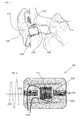
- FIG. 1illustrates general physiology of an ear
- FIG. 2illustrates an attenuation varying device in accordance with an embodiment
- FIGS. 3A-3Cillustrates an attenuation varying device in accordance with an embodiment, and acoustic generating devices
- FIGS. 4A-4Cillustrates an attenuation varying device in accordance with an embodiment, and acoustic generating devices
- FIG. 5illustrates a speaker and/or microphone in accordance with at least one embodiment
- FIG. 6illustrates a speaker and/or microphone in accordance with at least one embodiment
- FIG. 7illustrates sound pressure levels measured from a device in accordance with at least one embodiment
- FIG. 8illustrates insertion loss from a device in accordance with at least one embodiment.
- Exemplary embodimentsare directed to or can be operatively used on various wired or wireless earpieces devices (e.g., earbuds, headphones, ear terminal, behind the ear devices or other acoustic devices as known by one of ordinary skill, and equivalents).
- the earpiecescan be without transducers (for a noise attenuation application) or one or more transducers (e.g. ambient sound microphone (ASM), ear canal microphone (ECM), ear canal receiver (ECR)) for monitoring/providing sound.
- ASMambient sound microphone
- ECMear canal microphone
- ECRear canal receiver
- Ferrofluidscan be composed of nanoscale particles (diameter usually 10 nanometers or less) of magnetite, hematite or some other compound containing iron. This is small enough for thermal agitation to disperse them evenly within a carrier fluid, and for them to contribute to the overall magnetic response of the fluid. Ferrofluids are tiny iron particles covered with a liquid coating, also surfactant that are then added to water or oil, which gives them their liquid properties. Ferrofluids are colloidal suspensions—materials with properties of more than one state of matter.
- the two states of matterare the solid metal and liquid it is in this ability to change phases with the application of a magnetic field allows them to be used as seals, lubricants, and may open up further applications in future nanoelectromechanical systems.
- a sample of ferrofluidcan be mixed with various other fluids (e.g., water, mineral oil, alcohol) to acquire various desired properties.
- water, mineral oil, alcohole.g., water, mineral oil, alcohol
- Such a systemcan be used as a pump to move fluid from one side of a bladder to another, or even into a separate region, for example where the water can react to an agent when the ferrofluid would not.
- Another example of a benefit to mixingis to vary the viscosity of the fluid. If the ferrofluid is mixed with mineral oil, the net fluid is less viscous and more easily moved, while remaining mixed when a magnetic field is applied. If the net fluid is in a reservoir chamber one can move the fluid into a different chamber by application of a magnetic field. Note that the discussion above applies equally well for an ER fluid where electric fields are applied instead of magnetic fields.
- MRFmagnetorheological fluid
- FFferrofluids
- Magnetorheological fluidshave micrometer scale magnetic particles that are one to three orders of magnitude larger than those of ferrofluids.
- ferrofluidslose their magnetic properties at sufficiently high temperatures, known as the Curie temperature. The specific temperature required varies depending on the specific compounds used for the nano-particles.
- the surfactants used to coat the nanoparticlesinclude, but are not limited to: oleic acid; tetramethylammonium hydroxide; citric acid; soy lecithin These surfactants prevent the nanoparticles from clumping together, ensuring that the particles do not form aggregates that become too heavy to be held in suspension by Brownian motion.
- the magnetic particles in an ideal ferrofluiddo not settle out, even when exposed to a strong magnetic, or gravitational field.
- a surfactanthas a polar head and non-polar tail (or vice versa), one of which adsorbs to a nanoparticle, while the non-polar tail (or polar head) sticks out into the carrier medium, forming an inverse or regular micelle, respectively, around the particle.
- Ferrofluidsin general comprise a colloidal suspension of very finely-divided magnetic particles dispersed in a liquid carrier, such as water or other organic liquids to include, but not limited to: liquid hydrocarbons, fluorocarbons, silicones, organic esters and diesters, and other stable inert liquids of the desired properties and viscosities.
- a liquid carriersuch as water or other organic liquids to include, but not limited to: liquid hydrocarbons, fluorocarbons, silicones, organic esters and diesters, and other stable inert liquids of the desired properties and viscosities.
- Ferrofluids of the type prepared and described in U.S. Pat. No. 3,917,538, issued Nov. 4, 1975, hereby incorporated by reference,may be employed.
- the ferrofluidis selected to have a desired viscous-dampening viscosity in the field; for example, viscosities at 25.degree. C.
- the magnetic material employedmay be magnetic material made from materials of the Alnico group, rare earth cobalt, or other materials providing a magnetic field, but typically comprises permanent magnetic material.
- the permanent magnetic materialis used as the seismic mass, it is axially polarized in the housing made of nonferromagnetic material, such as aluminum, zinc, plastic, etc., and the magnet creates a magnetic-force field which equally distributes the enclosed ferrofluid in the annular volume of the housing and on the planar faces of the housing walls.
- FIG. 1illustrates general physiology of an ear.
- the earcomprises a pinna 100 , concha 110 , ear canal wall 120 , and tympanic membrane 140 .
- Pinna 100is an external portion of the ear.
- Pinna 100is a cartilaginous region of the ear that focuses acoustic information from an ambient environment to an ear canal 130 .
- Concha 110is also an external portion of the ear.
- Concha 110is a bowl shaped region in proximity to the ear canal opening.
- a dashed line 150indicates an opening to the ear (aperture) where sound enters to be received by tympanic membrane 140 .
- the ear canal wall 120forms an acoustic chamber known as ear canal 130 .
- Ear canal shapes and sizesvary substantially over the human population.
- Ear canal 130terminates in tympanic membrane 140 .
- Tympanic membrane 140is a flexible membrane in the middle ear that couples to components of the inner ear.
- the acoustic information resident in ear canal 130vibrates tympanic membrane 120 that is converted to a signal (corresponding to the sound) that is provided to the auditory nerve.
- FIG. 2illustrates at least one non-limiting example of an electrically controlled acoustic control system that controls the amount of acoustic intensity (which can be frequency dependent) passing through the device 200 .
- acoustical energyis used although such a system can also be used for other various energy inputs (e.g., light, heat, conductivity).
- An acoustic wave 210impinges upon the device 200 , whereupon a portion 215 travels adjacent to the control tube and is attenuated by the material of device 200 (e.g., foam material for earplugs or polymers for flanges).
- Fluid reservoir 230e.g., containing FF, MRF, electro fluid (EF and ERF)
- EF and ERFelectro fluid
- a magnetic coil 250provides the method to vary the magnetic field which varies the material properties of MRF and/or FF in eth reservoir 230 , thus altering the energy transmitted 240 .
- a non limiting example of the use of such a systemwould be for combat earplugs.
- an ambient microphonedetects a gun shot or other acoustic event of a particular SPL a signal can be sent to a processor directing a certain level of current to be sent to the coil to provide a higher level of attenuation or lower level of transmitted energy 240 .
- a processordirecting a certain level of current to be sent to the coil to provide a higher level of attenuation or lower level of transmitted energy 240 .
- Such a systemhas an advantage over conventional systems since the enhanced acoustic SPL can be detected and reacted to faster than arrival time, providing real time protection of a user.
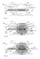
- FIGS. 3A-3Cillustrates an attenuation varying device in accordance with an embodiment, and acoustic generating devices.
- an earpiecesuch as an earplug is referred to, however the principals discussed are also applicable to stand alone speakers and microphones (e.g., FIG. 5 and FIG. 6 ).
- FIGS. 3A-3Cillustrate an earpiece 300 inserted into a channel (e.g., pipe, ear canal, vein).
- An incident energy (e.g. acoustic) 320is incident upon a housing 350 (e.g., flexible) which includes a field responsive medium (FRM) 370 (e.g., ER, MR).
- FAMfield responsive medium
- the FRM 370is delivered through an insertion input 360 to and from the housing 350 via a channel 340 in a tube 330 .
- the non-limiting example illustrated in FIG. 3Aillustrates a coil around the tube 330 connected to current source 305 .
- FIG. 3Aillustrates no current and thus a passive attenuation is achieved as a function of medium composition of the FRM 370 and the pressure. Thus a portion of the incident energy passes the earpiece in the form of transmitted energy 325 .
- electric fieldsserve the same function as the magnetic fields in FIGS. 3A-3C . Note that FRM 375 and 475 can have non-homogenous effects.
- acoustical energycan pass along the field lines differently than perpendicular to them, thus one can control the flow of acoustic energy by changing the orientation of magnetic field lines. Likewise one can control the acoustic energy direction by caging electric field lines.
- FIG. 3Billustrates the earpiece 300 with a steady current 306 imposed on the coil, creating magnetic field lines 380 , which modify the FRM 370 to form FRM 375 .
- FRM 375reacts to the magnetic field lines 380 and hence its material properties have changed. For example acoustical energy may be reduced while passing through FRM 375 , since the fluid is now restricted as to its movement.
- FIG. 8illustrates insertion loss values as a function of magnetic field. For example 810 shows the insertion loss (IL) versus frequency for a balloon system filled with an FRM with no imposed magnetic field at a gauge pressure of 390 mbar. 820 shows the same FRM with a strong magnetic field imposed whose field lines are similar as illustrated in FIG. 3B .
- ILinsertion loss
- FIG. 3Cillustrates the effect of a temporal variable field generated by varying current 307 .
- the varying magnetic fieldvaries the conditions in the FRM 375 , thus oscillating FRM 375 .
- This oscillationcan produce energy of its own 391 .
- FIG. 7illustrates sound pressure levels (SPL) as a function of frequency in a channel.
- 710illustrates the sound passing through the channel when there is no inflation of the device (e.g., 300 ).
- the peak value of 710is about 114 dB at about 2 kHz.
- FIG. 730illustrates the SPL when the housing (e.g., 350 , 450 ) is inflated to a pressure of about 290 mbar. Note that for an earpiece pressures can vary from 100 mbar to 3000 mbar depending upon FRM.
- a low frequency B(t)or E(t) is induced FRM ( 375 , 475 ) varies in response.
- the variation (e.g., density variation, flows induced) in the FRMmove the housing generating energy (e.g., acoustic 391 , 491 ).
- energye.g., acoustic 391 , 491 .
- FIGS. 4A-4Cillustrates an attenuation varying device in accordance with an embodiment, and acoustic generating devices.
- FIGS. 4A-4Care similar to FIGS. 3A-3C however FIGS. 4A-4C illustrate embodiments using an FRM that is responsive to electric fields 480 , 485 .
- conductive electrodese.g. insulted and/or noninsulated
- FRMresponds by changing (e.g., fluid flow, density changes).
- FIG. 5illustrates a speaker and/or microphone in accordance with at least one embodiment
- FIG. 6illustrates a speaker and/or microphone in accordance with at least one embodiment.
- onecan vary current and/or voltage to generate acoustical energy 591 , and 691 .
- a steady fieldis imposed, for example if 510 and/or 610 were steady, then when sound impinges upon FRM 575 and/or 675 and induced current and/or voltage is generated.
- the induced current and/or voltagecan be converted by known methods to pick up sound making device 500 and 600 microphones.
- devices 500 and 600can have internally induced currents 507 and voltages 607 generating sounds, making the devices speakers.
Landscapes
- Physics & Mathematics (AREA)
- Engineering & Computer Science (AREA)
- Acoustics & Sound (AREA)
- Signal Processing (AREA)
- Multimedia (AREA)
- Soundproofing, Sound Blocking, And Sound Damping (AREA)
- Headphones And Earphones (AREA)
Abstract
Description
Claims (12)
Priority Applications (5)
| Application Number | Priority Date | Filing Date | Title |
|---|---|---|---|
| US13/154,429US9123323B2 (en) | 2010-06-04 | 2011-06-06 | Method and structure for inducing acoustic signals and attenuating acoustic signals |
| US13/859,815US20140373854A1 (en) | 2011-05-31 | 2013-04-10 | Method and structure for achieveing acoustically spectrum tunable earpieces, panels, and inserts |
| US14/807,887US20160192077A1 (en) | 2010-06-04 | 2015-07-24 | Method and structure for inducing acoustic signals and attenuating acoustic signals |
| US15/182,569US20160295311A1 (en) | 2010-06-04 | 2016-06-14 | Earplugs, earphones, panels, inserts and safety methods |
| US15/674,239US20180220239A1 (en) | 2010-06-04 | 2017-08-10 | Earplugs, earphones, and eartips |
Applications Claiming Priority (2)
| Application Number | Priority Date | Filing Date | Title |
|---|---|---|---|
| US35129010P | 2010-06-04 | 2010-06-04 | |
| US13/154,429US9123323B2 (en) | 2010-06-04 | 2011-06-06 | Method and structure for inducing acoustic signals and attenuating acoustic signals |
Related Parent Applications (1)
| Application Number | Title | Priority Date | Filing Date |
|---|---|---|---|
| US15/182,569Continuation-In-PartUS20160295311A1 (en) | 2010-06-04 | 2016-06-14 | Earplugs, earphones, panels, inserts and safety methods |
Related Child Applications (2)
| Application Number | Title | Priority Date | Filing Date |
|---|---|---|---|
| US13/859,815Continuation-In-PartUS20140373854A1 (en) | 2010-06-04 | 2013-04-10 | Method and structure for achieveing acoustically spectrum tunable earpieces, panels, and inserts |
| US14/807,887ContinuationUS20160192077A1 (en) | 2010-06-04 | 2015-07-24 | Method and structure for inducing acoustic signals and attenuating acoustic signals |
Publications (2)
| Publication Number | Publication Date |
|---|---|
| US20110311079A1 US20110311079A1 (en) | 2011-12-22 |
| US9123323B2true US9123323B2 (en) | 2015-09-01 |
Family
ID=45328697
Family Applications (2)
| Application Number | Title | Priority Date | Filing Date |
|---|---|---|---|
| US13/154,429Active - Reinstated2032-02-25US9123323B2 (en) | 2010-06-04 | 2011-06-06 | Method and structure for inducing acoustic signals and attenuating acoustic signals |
| US14/807,887AbandonedUS20160192077A1 (en) | 2010-06-04 | 2015-07-24 | Method and structure for inducing acoustic signals and attenuating acoustic signals |
Family Applications After (1)
| Application Number | Title | Priority Date | Filing Date |
|---|---|---|---|
| US14/807,887AbandonedUS20160192077A1 (en) | 2010-06-04 | 2015-07-24 | Method and structure for inducing acoustic signals and attenuating acoustic signals |
Country Status (1)
| Country | Link |
|---|---|
| US (2) | US9123323B2 (en) |
Cited By (19)
| Publication number | Priority date | Publication date | Assignee | Title |
|---|---|---|---|---|
| US20170040012A1 (en)* | 2015-05-29 | 2017-02-09 | Steven Wayne Goldstein | Methods and devices for attenuating sound in a conduit or chamber |
| US10362381B2 (en) | 2011-06-01 | 2019-07-23 | Staton Techiya, Llc | Methods and devices for radio frequency (RF) mitigation proximate the ear |
| US10409860B2 (en) | 2011-03-28 | 2019-09-10 | Staton Techiya, Llc | Methods and systems for searching utilizing acoustical context |
| US10413240B2 (en) | 2014-12-10 | 2019-09-17 | Staton Techiya, Llc | Membrane and balloon systems and designs for conduits |
| US10455315B2 (en) | 2008-10-10 | 2019-10-22 | Staton Techiya Llc | Inverted balloon system and inflation management system |
| US10616693B2 (en) | 2016-01-22 | 2020-04-07 | Staton Techiya Llc | System and method for efficiency among devices |
| US10622005B2 (en) | 2013-01-15 | 2020-04-14 | Staton Techiya, Llc | Method and device for spectral expansion for an audio signal |
| US10636436B2 (en) | 2013-12-23 | 2020-04-28 | Staton Techiya, Llc | Method and device for spectral expansion for an audio signal |
| US10709388B2 (en) | 2015-05-08 | 2020-07-14 | Staton Techiya, Llc | Biometric, physiological or environmental monitoring using a closed chamber |
| US10715940B2 (en) | 2008-10-15 | 2020-07-14 | Staton Techiya, Llc | Device and method to reduce ear wax clogging of acoustic ports, hearing aid sealing sytem, and feedback reduction system |
| US10757496B2 (en) | 2010-06-26 | 2020-08-25 | Staton Techiya, Llc | Methods and devices for occluding an ear canal having a predetermined filter characteristic |
| US10764226B2 (en) | 2016-01-15 | 2020-09-01 | Staton Techiya, Llc | Message delivery and presentation methods, systems and devices using receptivity |
| US10824388B2 (en) | 2014-10-24 | 2020-11-03 | Staton Techiya, Llc | Robust voice activity detector system for use with an earphone |
| US10937407B2 (en) | 2015-10-26 | 2021-03-02 | Staton Techiya, Llc | Biometric, physiological or environmental monitoring using a closed chamber |
| US11006199B2 (en) | 2012-12-17 | 2021-05-11 | Staton Techiya, Llc | Methods and mechanisms for inflation |
| US11266533B2 (en) | 2012-09-04 | 2022-03-08 | Staton Techiya, Llc | Occlusion device capable of occluding an ear canal |
| US11291456B2 (en) | 2007-07-12 | 2022-04-05 | Staton Techiya, Llc | Expandable sealing devices and methods |
| US12183341B2 (en) | 2008-09-22 | 2024-12-31 | St Casestech, Llc | Personalized sound management and method |
| US12249326B2 (en) | 2007-04-13 | 2025-03-11 | St Case1Tech, Llc | Method and device for voice operated control |
Families Citing this family (9)
| Publication number | Priority date | Publication date | Assignee | Title |
|---|---|---|---|---|
| US20130149192A1 (en)* | 2011-09-08 | 2013-06-13 | John P. Keady | Method and structure for generating and receiving acoustic signals and eradicating viral infections |
| US8550206B2 (en) | 2011-05-31 | 2013-10-08 | Virginia Tech Intellectual Properties, Inc. | Method and structure for achieving spectrum-tunable and uniform attenuation |
| US9333116B2 (en) | 2013-03-15 | 2016-05-10 | Natan Bauman | Variable sound attenuator |
| US9521480B2 (en) | 2013-07-31 | 2016-12-13 | Natan Bauman | Variable noise attenuator with adjustable attenuation |
| US10045133B2 (en) | 2013-03-15 | 2018-08-07 | Natan Bauman | Variable sound attenuator with hearing aid |
| US10341764B2 (en)* | 2013-05-23 | 2019-07-02 | Derek Barrentine | Structures for dynamically tuned audio in a media device |
| EP3195611B1 (en) | 2014-09-19 | 2020-09-09 | 3M Innovative Properties Company | Acoustically probed over-the-ear hearing assessment devices and methods |
| US11477560B2 (en) | 2015-09-11 | 2022-10-18 | Hear Llc | Earplugs, earphones, and eartips |
| US10455318B2 (en) | 2017-05-03 | 2019-10-22 | Honeywell International Inc. | Earmuff with electroacoustic shock absorber |
Citations (10)
| Publication number | Priority date | Publication date | Assignee | Title |
|---|---|---|---|---|
| US4361879A (en)* | 1980-08-25 | 1982-11-30 | The United States Of America As Represented By The Secretary Of The Navy | Ferrofluid transducer |
| US5452268A (en)* | 1994-08-12 | 1995-09-19 | The Charles Stark Draper Laboratory, Inc. | Acoustic transducer with improved low frequency response |
| US20030147538A1 (en)* | 2002-02-05 | 2003-08-07 | Mh Acoustics, Llc, A Delaware Corporation | Reducing noise in audio systems |
| US20040228494A1 (en)* | 1999-10-28 | 2004-11-18 | Clive Smith | Transducer for sensing body sounds |
| US20050185813A1 (en)* | 2004-02-24 | 2005-08-25 | Microsoft Corporation | Method and apparatus for multi-sensory speech enhancement on a mobile device |
| US20050222487A1 (en)* | 2004-04-01 | 2005-10-06 | Miller Scott A Iii | Low acceleration sensitivity microphone |
| US20060050916A1 (en)* | 2002-10-31 | 2006-03-09 | Raymond Wehner | Microphone in a cylindrical housing having elliptical end faces |
| US7132597B2 (en)* | 2002-02-26 | 2006-11-07 | Taylor-Listug, Inc. | Transducer for converting between mechanical vibration and electrical signal |
| US20070003087A1 (en)* | 2005-06-30 | 2007-01-04 | Insound Medical, Inc. | Hearing aid microphone protective barrier |
| US20070104344A1 (en)* | 2004-12-20 | 2007-05-10 | Josh Goldberg | Hearing Aid Mechanism |
Family Cites Families (1)
| Publication number | Priority date | Publication date | Assignee | Title |
|---|---|---|---|---|
| US4497208A (en)* | 1983-06-23 | 1985-02-05 | Matec, Inc. | Measurement of electro-kinetic properties of a solution |
- 2011
- 2011-06-06USUS13/154,429patent/US9123323B2/enactiveActive - Reinstated
- 2015
- 2015-07-24USUS14/807,887patent/US20160192077A1/ennot_activeAbandoned
Patent Citations (10)
| Publication number | Priority date | Publication date | Assignee | Title |
|---|---|---|---|---|
| US4361879A (en)* | 1980-08-25 | 1982-11-30 | The United States Of America As Represented By The Secretary Of The Navy | Ferrofluid transducer |
| US5452268A (en)* | 1994-08-12 | 1995-09-19 | The Charles Stark Draper Laboratory, Inc. | Acoustic transducer with improved low frequency response |
| US20040228494A1 (en)* | 1999-10-28 | 2004-11-18 | Clive Smith | Transducer for sensing body sounds |
| US20030147538A1 (en)* | 2002-02-05 | 2003-08-07 | Mh Acoustics, Llc, A Delaware Corporation | Reducing noise in audio systems |
| US7132597B2 (en)* | 2002-02-26 | 2006-11-07 | Taylor-Listug, Inc. | Transducer for converting between mechanical vibration and electrical signal |
| US20060050916A1 (en)* | 2002-10-31 | 2006-03-09 | Raymond Wehner | Microphone in a cylindrical housing having elliptical end faces |
| US20050185813A1 (en)* | 2004-02-24 | 2005-08-25 | Microsoft Corporation | Method and apparatus for multi-sensory speech enhancement on a mobile device |
| US20050222487A1 (en)* | 2004-04-01 | 2005-10-06 | Miller Scott A Iii | Low acceleration sensitivity microphone |
| US20070104344A1 (en)* | 2004-12-20 | 2007-05-10 | Josh Goldberg | Hearing Aid Mechanism |
| US20070003087A1 (en)* | 2005-06-30 | 2007-01-04 | Insound Medical, Inc. | Hearing aid microphone protective barrier |
Cited By (40)
| Publication number | Priority date | Publication date | Assignee | Title |
|---|---|---|---|---|
| US12249326B2 (en) | 2007-04-13 | 2025-03-11 | St Case1Tech, Llc | Method and device for voice operated control |
| US11291456B2 (en) | 2007-07-12 | 2022-04-05 | Staton Techiya, Llc | Expandable sealing devices and methods |
| US12183341B2 (en) | 2008-09-22 | 2024-12-31 | St Casestech, Llc | Personalized sound management and method |
| US12374332B2 (en) | 2008-09-22 | 2025-07-29 | ST Fam Tech, LLC | Personalized sound management and method |
| US11159876B2 (en) | 2008-10-10 | 2021-10-26 | Staton Techiya Llc | Inverted balloon system and inflation management system |
| US10455315B2 (en) | 2008-10-10 | 2019-10-22 | Staton Techiya Llc | Inverted balloon system and inflation management system |
| US10897678B2 (en) | 2008-10-15 | 2021-01-19 | Staton Techiya, Llc | Device and method to reduce ear wax clogging of acoustic ports, hearing aid sealing system, and feedback reduction system |
| US10979831B2 (en) | 2008-10-15 | 2021-04-13 | Staton Techiya, Llc | Device and method to reduce ear wax clogging of acoustic ports, hearing aid sealing system, and feedback reduction system |
| US10715940B2 (en) | 2008-10-15 | 2020-07-14 | Staton Techiya, Llc | Device and method to reduce ear wax clogging of acoustic ports, hearing aid sealing sytem, and feedback reduction system |
| US11611820B2 (en) | 2010-06-26 | 2023-03-21 | Staton Techiya Llc | Methods and devices for occluding an ear canal having a predetermined filter characteristic |
| US10757496B2 (en) | 2010-06-26 | 2020-08-25 | Staton Techiya, Llc | Methods and devices for occluding an ear canal having a predetermined filter characteristic |
| US11388500B2 (en) | 2010-06-26 | 2022-07-12 | Staton Techiya, Llc | Methods and devices for occluding an ear canal having a predetermined filter characteristic |
| US12174901B2 (en) | 2011-03-28 | 2024-12-24 | Apple Inc. | Methods and systems for searching utilizing acoustical context |
| US10409860B2 (en) | 2011-03-28 | 2019-09-10 | Staton Techiya, Llc | Methods and systems for searching utilizing acoustical context |
| US11310580B2 (en) | 2011-06-01 | 2022-04-19 | Staton Techiya, Llc | Methods and devices for radio frequency (RF) mitigation proximate the ear |
| US10575081B2 (en) | 2011-06-01 | 2020-02-25 | Staton Techiya, Llc | Methods and devices for radio frequency (RF) mitigation proximate the ear |
| US11483641B2 (en) | 2011-06-01 | 2022-10-25 | Staton Techiya, Llc | Methods and devices for radio frequency (RF) mitigation proximate the ear |
| US11729539B2 (en) | 2011-06-01 | 2023-08-15 | Staton Techiya Llc | Methods and devices for radio frequency (RF) mitigation proximate the ear |
| US20220191608A1 (en) | 2011-06-01 | 2022-06-16 | Staton Techiya Llc | Methods and devices for radio frequency (rf) mitigation proximate the ear |
| US11832044B2 (en) | 2011-06-01 | 2023-11-28 | Staton Techiya Llc | Methods and devices for radio frequency (RF) mitigation proximate the ear |
| US10362381B2 (en) | 2011-06-01 | 2019-07-23 | Staton Techiya, Llc | Methods and devices for radio frequency (RF) mitigation proximate the ear |
| US11730630B2 (en) | 2012-09-04 | 2023-08-22 | Staton Techiya Llc | Occlusion device capable of occluding an ear canal |
| US11266533B2 (en) | 2012-09-04 | 2022-03-08 | Staton Techiya, Llc | Occlusion device capable of occluding an ear canal |
| US11659315B2 (en) | 2012-12-17 | 2023-05-23 | Staton Techiya Llc | Methods and mechanisms for inflation |
| US11006199B2 (en) | 2012-12-17 | 2021-05-11 | Staton Techiya, Llc | Methods and mechanisms for inflation |
| US12236971B2 (en) | 2013-01-15 | 2025-02-25 | ST R&DTech LLC | Method and device for spectral expansion of an audio signal |
| US10622005B2 (en) | 2013-01-15 | 2020-04-14 | Staton Techiya, Llc | Method and device for spectral expansion for an audio signal |
| US10636436B2 (en) | 2013-12-23 | 2020-04-28 | Staton Techiya, Llc | Method and device for spectral expansion for an audio signal |
| US10824388B2 (en) | 2014-10-24 | 2020-11-03 | Staton Techiya, Llc | Robust voice activity detector system for use with an earphone |
| US10413240B2 (en) | 2014-12-10 | 2019-09-17 | Staton Techiya, Llc | Membrane and balloon systems and designs for conduits |
| US10709388B2 (en) | 2015-05-08 | 2020-07-14 | Staton Techiya, Llc | Biometric, physiological or environmental monitoring using a closed chamber |
| US11430422B2 (en) | 2015-05-29 | 2022-08-30 | Staton Techiya Llc | Methods and devices for attenuating sound in a conduit or chamber |
| US20170040012A1 (en)* | 2015-05-29 | 2017-02-09 | Steven Wayne Goldstein | Methods and devices for attenuating sound in a conduit or chamber |
| US10418016B2 (en)* | 2015-05-29 | 2019-09-17 | Staton Techiya, Llc | Methods and devices for attenuating sound in a conduit or chamber |
| US10937407B2 (en) | 2015-10-26 | 2021-03-02 | Staton Techiya, Llc | Biometric, physiological or environmental monitoring using a closed chamber |
| US10764226B2 (en) | 2016-01-15 | 2020-09-01 | Staton Techiya, Llc | Message delivery and presentation methods, systems and devices using receptivity |
| US11595762B2 (en) | 2016-01-22 | 2023-02-28 | Staton Techiya Llc | System and method for efficiency among devices |
| US10616693B2 (en) | 2016-01-22 | 2020-04-07 | Staton Techiya Llc | System and method for efficiency among devices |
| US11917367B2 (en) | 2016-01-22 | 2024-02-27 | Staton Techiya Llc | System and method for efficiency among devices |
| US10904674B2 (en) | 2016-01-22 | 2021-01-26 | Staton Techiya, Llc | System and method for efficiency among devices |
Also Published As
| Publication number | Publication date |
|---|---|
| US20110311079A1 (en) | 2011-12-22 |
| US20160192077A1 (en) | 2016-06-30 |
Similar Documents
| Publication | Publication Date | Title |
|---|---|---|
| US9123323B2 (en) | Method and structure for inducing acoustic signals and attenuating acoustic signals | |
| CN106375915B (en) | A speaker and earphones | |
| JP7385626B2 (en) | transducer placement | |
| JP6649488B2 (en) | Noise shielding earset with acoustic filter | |
| US9301034B2 (en) | Magnetic suspension transducer | |
| US20130149192A1 (en) | Method and structure for generating and receiving acoustic signals and eradicating viral infections | |
| US7206425B2 (en) | Actuator for an active noise control system | |
| US20200366996A1 (en) | Sound output device, earphone, hearing aid, and mobile terminal device | |
| US11991500B2 (en) | Systems and methods for suppressing sound leakage | |
| JP2006304262A (en) | Vibration-sound generating device and yoke thereof | |
| JP2014530104A (en) | Vibration transducers and actuators | |
| CN204118999U (en) | For the motor of receiver | |
| US20210219074A1 (en) | Systems and methods for suppressing sound leakage | |
| CN204119001U (en) | For the motor of receiver | |
| Raj et al. | New commercial trends of nanostructured ferrofluids | |
| US8428297B2 (en) | Acoustic transducer | |
| EP3399770B1 (en) | Earmuff with electroacoustic shock absorber | |
| CN208143457U (en) | Moving-coil structure and earphone | |
| Jiang et al. | Design and analysis of two-way microspeaker to enhance mid-frequency sound pressure level | |
| US20230156412A1 (en) | Systems and methods for suppressing sound leakage | |
| TWI542225B (en) | Audio playback device | |
| JP2012015716A (en) | Speaker driving control system | |
| Rémy | Innovative ironless loudspeaker motor adapted to automotive audio | |
| Jovic | A comparison between dynamic loudspeakers and plasma loudspeakers | |
| CN111479200A (en) | Planar moving magnet speaker |
Legal Events
| Date | Code | Title | Description |
|---|---|---|---|
| ZAAA | Notice of allowance and fees due | Free format text:ORIGINAL CODE: NOA | |
| ZAAB | Notice of allowance mailed | Free format text:ORIGINAL CODE: MN/=. | |
| ZAAA | Notice of allowance and fees due | Free format text:ORIGINAL CODE: NOA | |
| STCF | Information on status: patent grant | Free format text:PATENTED CASE | |
| MAFP | Maintenance fee payment | Free format text:PAYMENT OF MAINTENANCE FEE, 4TH YR, SMALL ENTITY (ORIGINAL EVENT CODE: M2551); ENTITY STATUS OF PATENT OWNER: SMALL ENTITY Year of fee payment:4 | |
| FEPP | Fee payment procedure | Free format text:MAINTENANCE FEE REMINDER MAILED (ORIGINAL EVENT CODE: REM.); ENTITY STATUS OF PATENT OWNER: SMALL ENTITY | |
| AS | Assignment | Owner name:STATON TECHIYA, LLC, FLORIDA Free format text:ASSIGNMENT OF ASSIGNORS INTEREST;ASSIGNOR:KEADY, JOHN PATRICK;REEL/FRAME:064717/0550 Effective date:20230828 | |
| LAPS | Lapse for failure to pay maintenance fees | Free format text:PATENT EXPIRED FOR FAILURE TO PAY MAINTENANCE FEES (ORIGINAL EVENT CODE: EXP.); ENTITY STATUS OF PATENT OWNER: SMALL ENTITY | |
| PRDP | Patent reinstated due to the acceptance of a late maintenance fee | Effective date:20231010 | |
| FEPP | Fee payment procedure | Free format text:PETITION RELATED TO MAINTENANCE FEES FILED (ORIGINAL EVENT CODE: PMFP); ENTITY STATUS OF PATENT OWNER: SMALL ENTITY Free format text:PETITION RELATED TO MAINTENANCE FEES GRANTED (ORIGINAL EVENT CODE: PMFG); ENTITY STATUS OF PATENT OWNER: SMALL ENTITY Free format text:SURCHARGE, PETITION TO ACCEPT PYMT AFTER EXP, UNINTENTIONAL. (ORIGINAL EVENT CODE: M2558); ENTITY STATUS OF PATENT OWNER: SMALL ENTITY | |
| MAFP | Maintenance fee payment | Free format text:PAYMENT OF MAINTENANCE FEE, 8TH YR, SMALL ENTITY (ORIGINAL EVENT CODE: M2552); ENTITY STATUS OF PATENT OWNER: SMALL ENTITY Year of fee payment:8 | |
| STCF | Information on status: patent grant | Free format text:PATENTED CASE | |
| FP | Lapsed due to failure to pay maintenance fee | Effective date:20230901 | |
| AS | Assignment | Owner name:ST PORTFOLIO HOLDINGS, LLC, FLORIDA Free format text:ASSIGNMENT OF ASSIGNORS INTEREST;ASSIGNOR:STATON TECHIYA, LLC;REEL/FRAME:067806/0740 Effective date:20240612 Owner name:ST TIPTECH, LLC, FLORIDA Free format text:ASSIGNMENT OF ASSIGNORS INTEREST;ASSIGNOR:ST PORTFOLIO HOLDINGS, LLC;REEL/FRAME:067806/0769 Effective date:20240612 |