US9122817B2 - Collaborative CAx apparatus and method - Google Patents
Collaborative CAx apparatus and methodDownload PDFInfo
- Publication number
- US9122817B2 US9122817B2US13/156,453US201113156453AUS9122817B2US 9122817 B2US9122817 B2US 9122817B2US 201113156453 AUS201113156453 AUS 201113156453AUS 9122817 B2US9122817 B2US 9122817B2
- Authority
- US
- United States
- Prior art keywords
- user
- tools
- engineering object
- editable feature
- editing
- Prior art date
- Legal status (The legal status is an assumption and is not a legal conclusion. Google has not performed a legal analysis and makes no representation as to the accuracy of the status listed.)
- Expired - Fee Related, expires
Links
Images


Classifications
- G06F17/50—
- G—PHYSICS
- G06—COMPUTING OR CALCULATING; COUNTING
- G06F—ELECTRIC DIGITAL DATA PROCESSING
- G06F30/00—Computer-aided design [CAD]
- G—PHYSICS
- G06—COMPUTING OR CALCULATING; COUNTING
- G06F—ELECTRIC DIGITAL DATA PROCESSING
- G06F2111/00—Details relating to CAD techniques
- G06F2111/02—CAD in a network environment, e.g. collaborative CAD or distributed simulation
- G06F2217/04—
Definitions
- the claimed inventionrelates to computer aided technologies (CAx) such as computer aided design, engineering, analysis and manufacture in general and means and methods for collaborative CAx in particular.
- CAxcomputer aided technologies
- CAx applicationstypically require that a single user assume ownership and control of a design or engineering model (e.g. a file or database record) in order to prohibit multiple users from making uncoordinated changes to the model.
- a design or engineering modele.g. a file or database record
- the present inventionhas been developed in response to the present state of the art, and in particular, in response to the problems and needs in the art that have not yet been fully solved by currently available CAx apparatii and methods. Accordingly, the claimed inventions have been developed to provide a collaborative CAx apparatus and method that overcomes shortcomings in the art.
- an apparatus for collaborative editing of an electronic model of a CAx objectmay include a datastore that stores an electronic model of an engineering object that is spatially decomposed into a plurality of editing regions.
- the apparatusmay also include a change control module that enables a user of a plurality of concurrent users to make changes to an editable feature corresponding to a particular editing region.
- the change control modulemay also inhibit the user from making changes to an editable feature corresponding to an editing region assigned to another user.
- a method for collaborative editing of an electronic model of a CAx objectmay include providing access to an electronic model that is spatially decomposed into a plurality of editing regions, enabling a user to make changes to an editable feature corresponding to a particular editing region and blocking the user from making changes to an editable feature corresponding to an editing region assigned to another user.
- FIG. 1is a block diagram of one example of a computing and communications infrastructure that is consistent with one or more embodiments of the claimed invention
- FIG. 2is a block diagram of one example of a collaborative CAx editing system that is consistent with one or more embodiments of the claimed invention
- FIGS. 3-5are block diagrams of several embodiments of the collaborative CAx editing system of FIG. 2 as applied to various computing architectures;
- FIG. 6is a flowchart diagram of one example of a collaborative CAx editing method that is consistent with one or more embodiments of the claimed invention.
- FIG. 7is a graphical and textual depiction of one example of a collaborative CAx user interface that is consistent with one or more embodiments of the claimed invention.
- modulesmay be implemented as a hardware circuit comprising custom VLSI circuits or gate arrays, off-the-shelf semiconductors such as logic chips, transistors, or other discrete components.
- a modulemay also be implemented in programmable hardware devices such as field programmable gate arrays, programmable array logic, programmable logic devices or the like.
- Modulesmay also be implemented in software for execution by various types of processors.
- An identified module of executable codemay, for instance, comprise one or more physical or logical blocks of computer instructions which may, for instance, be organized as an object, procedure, or function. Nevertheless, the executables of an identified module need not be physically located together, but may comprise disparate instructions stored in different locations which, when joined logically together, comprise the module and achieve the stated purpose for the module.
- a module of executable codemay be a single instruction, or many instructions, and may even be distributed over several different code segments, among different programs, and across several memory devices.
- operational datamay be identified and illustrated herein within modules, and may be embodied in any suitable form and organized within any suitable type of data structure. The operational data may be collected as a single data set, or may be distributed over different locations including over different storage devices, and may exist, at least partially, merely as electronic signals on a system or network.
- Reference to a computer readable mediummay take any form capable of enabling execution of a program of machine-readable instructions on a digital processing apparatus.
- a computer readable mediummay be embodied by a flash drive, compact disk, digital-video disk, a magnetic tape, a Bernoulli drive, a magnetic disk, a punch card, flash memory, integrated circuits, or other digital processing apparatus memory device.
- a digital processing apparatussuch as a computer may store program codes, associated data, and the like on the computer readable medium that when retrieved enable the digital processing apparatus to execute the functionality specified by the modules.
- CAx objectrefers to an electronically modeled object that may be edited by a CAx application or tool and ‘CAx model’ refers to the electronic model for that object.
- CAx applications and toolsinclude, but are not limited to, design tools, meshing tools, simulation tools, visualization tools, analysis tools, manufacture planning tools, and manufacture simulation tools.
- FIG. 1is a block diagram of one example of a computing and communications infrastructure 100 that is consistent with one or more embodiments of the claimed invention.
- the infrastructure 100includes various systems, subsystems, and networks such as a public switched telephone network (PSTN) 110 , a TDM gateway 120 connecting the PSTN to an inter-network 130 , a variety of workstations 125 , a data center 140 with administrative terminals 145 , an inter-network gateway 150 connecting a local area network to the inter-network 130 , and various servers such as application servers 170 , communication servers 180 , and data servers 190 .
- the infrastructure 100is one example of components that can be operably interconnected to provide an infrastructure for a collaborative CAx system.
- Each workstation 125may include a separate computing device 126 and a communications device 127 or the computing device and communications device may integrated into the workstation 125 .
- the computing devices 126may enable graphical editing and viewing of CAx models.
- the communications devices 127may enable users to communicate with other users that are concurrently editing a CAx model.
- the inter-network 130may facilitate electronic communications between the various workstations and servers.
- the inter-network 130is the internet.
- the inter-network 130is a virtual private network (VPN).
- VPNvirtual private network
- Various serverssuch as blade servers within the data center 140 function cooperatively to facilitate concurrent collaborative editing of CAx models by local and remote users.
- the application servers 170may provide one or more collaborative CAx applications to the local and remote users. Some users may have the collaborative CAx applications installed on their local computing devices 126 .
- the communication servers 180may facilitate communications between the users through various channels or services such as VOIP services, email services, instant messaging services, short message services, and text messaging services.
- the workstations 125may leverage such services for user to user communications via the communication servers 180 or via other available service platforms.
- the data servers 190 or the likemay store CAx models of design or engineering objects within various model files or records.
- the data serversmay replicate copies of the models for use by various users. Some users may have a local copy of a model.
- updates to the modelmay be coordinated by one or more collaborative CAx applications including client versions, server versions, and cloud versions of such applications.
- FIG. 2is a block diagram of one example of a collaborative CAx editing system 200 that is consistent with one or more embodiments of the claimed invention.
- the collaborative CAX editing system 200includes a variety of modules including a model datastore 210 , a change control module 220 , a user interface module 230 , a user-to-user communication module 240 , a version control module 250 , an object rendering module 260 , and a partitioning module 270 .
- Each of the modulesmay reside on a single computing device (i.e. node) or be collaboratively partitioned onto multiple devices or nodes.
- the depicted embodimentincludes a client node 200 a where the various modules are appended with the reference letter ‘a’ and a server node 200 b where the modules are appended with the reference letter ‘b’.
- the modulesmay be primarily or wholly comprised of software codes and associated data that are executed and processed by a digital processing apparatus such as a computer to provide the specified functionality.
- the model datastore 210stores data for the node(s) 200 .
- the model datastore 210may include an actual storage device or act as an interface to a storage device.
- the model datastore 210may enable the nodes 200 to store and retrieve files or other units of data such as database records that correspond to an electronic model (i.e. CAx model) of an engineering object.
- the model datastore 210may include working memory on the node 200 .
- the local model datastore 210 acontains local copies of CAx models managed by the global model datastore 210 b .
- the local and global model datastoresmay coordinate together to provide data coherency between local copies of the CAx models and the global copy.
- the global model datastoreis a redundant and/or a distributed storage system.
- the change control module 220controls user access to data managed by the model datastore 210 .
- the change control module 220ensures that users can only access data that corresponds to features within an editing region that has been assigned to the user. All other users may be blocked by the change control module 220 from accessing data corresponding to features within the editing region that has been assigned to that user. Examples of such features include the shape, dimensions, composition, material properties and tolerances of an object, the mesh size and required accuracy for simulations, the path and tolerances for a manufacturing tool, and any other attribute that may affect the performance of a product and the manufacture thereof.
- the change control module 220may also block an update to a CAx model if the changes to an editable feature violate engineering constraints associated with the modeled engineering object. For example, if changing the material of a particular component results in an increase in mass for the engineering object beyond a designated threshold, the change to the material may be blocked by the change control module 220 .
- the user interface module 230provides a user with a variety of interface elements that facilitate concurrent collaborative editing.
- interface elementsinclude interfaces elements for displaying a list of concurrent users, displaying user identifiers proximate to assigned editing regions, prioritizing user access rights and priorities (e.g. by an administrator), selecting user-to-user communication channels, initiating communication with another user, and providing access to software tools corresponding to various stages or layers associated with an engineering object.
- the user-to-user communication module 240facilitates direct communication between users.
- the user-to-user communication module 240may leverage a variety of communication services such as those detailed above in the description of the computing and communications infrastructure 100 . Communication may be between concurrent users as well as users that may not be actively editing an object.
- the interface elements provided by the user interface module 230may enable a user to select particular users or groups as a target for a particular message or ongoing conversation. Such communication is enabled by the user-to-user communication module 240 .
- the update module 245propagates changes to editable features between nodes of the collaborative editing system.
- the changesmay be communicated via one or more communication channels 280 such as peer-to-peer communication channels, client-server communication channels, and data replication channels associated with a cloud computing environment.
- valid changes to a local copy of an engineering modelare communicated by the client update module 245 a to the server update module 245 b within the server node 200 b .
- the server update module 245 bmay update additional client nodes 200 a.
- the version control module 250provides revision control capabilities to the collaborative editing environment.
- the version control module in conjunction with the user interface modulemay enable the concurrent users to select which revision of a product is to be updated with the edits.
- multiple revisionsmay be simultaneously edited.
- Revision controlmay also allow the collaborative users to discard edits associated with an editing session.
- the object rendering module 260renders the engineering object on a display for viewing by the user.
- the user interface module 230may overlay interface elements such as control points on the rendered engineering object.
- the partitioning module 270partitions the engineering object into one or more editing regions.
- the partitioningmay occur via spatial decomposition.
- the partitioningmay be automatic, for example when an engineering object is opened for editing, or user driven, for example in response to a user selecting a region or particular elements or features for editing.
- the local partitioning modules 270 ainitiate the partitioning process but the actual partitioning is performed by the global partitioning module 270 b or a process under control of the global partitioning module 270 b.
- FIGS. 3-5are block diagrams of several embodiments of the collaborative CAx editing system of FIG. 2 as applied to various computing architectures.
- FIG. 3depicts one example of a client-server embodiment
- FIG. 4depicts one example of a peer-to-peer embodiment
- FIG. 5depicts one example of a cloud embodiment. It should be noted that a variety of computing architectures beyond those shown in FIGS. 3-5 including emerging architectures may provide a computing infrastructure suitable for the collaborative CAx editing disclosed herein.
- the client-server embodiment depicted in FIG. 3includes a number of collaborative editing clients 310 that are in communication with a collaborative editing server 320 .
- the client 310is the node 200 a depicted in FIG. 2 and the server 320 is the node 200 b .
- the modules shown in FIG. 2may be partitioned between the client 310 and the server 320 in any useful manner that facilitates collaborative editing.
- the peer-to-peer embodiment depicted in FIG. 4includes a number of collaborative editing nodes 410 .
- each collaborative editing nodeincludes all of the modules of the client node 200 a along within distributed versions of the modules of the server node 200 b .
- each module of the server node 200 bis assigned to a particular collaborative editing node 410 .
- the cloud embodiment depicted in FIG. 5includes a number of collaborative editing nodes 410 similar to the peer-to-peer embodiment of FIG. 4 .
- the collaborative editing nodesmay be part of the inter-network 130 or one or more data centers 140 attached to the inter-network 130 .
- usersaccess a collaborative CAx application via a collaborative editing terminal 510 .
- the collaborative editing terminal 510is a thin client that only includes the modules of FIG. 2 (or portions thereof) that are necessary to support user interaction.
- FIG. 6is a flowchart diagram of one example of a collaborative CAx editing method 600 that is consistent with one or more embodiments of the claimed invention.
- the collaborative CAx editing method 600includes providing access 610 , enabling concurrent viewing 620 , initiating 630 spatial decomposition, enabling changes 640 by a user, blocking access 650 from other users, verifying 660 any engineering constraints, and updating 670 .
- Providing access 610may include providing an engineering model or a copy thereof to various computing devices or nodes associated with collaborative users.
- Enabling concurrent viewing 620may include providing tools or modules for rendering the engineering model to the collaborative users.
- Initiating 630 spatial decompositionmay include local or remote invocation of a function that spatially decomposes the engineering object into a plurality of editing regions.
- the editing regionsare automatically generated.
- regionsare established in response to users selecting a feature for editing.
- the partitioning module 270may check dependencies between geometries and features and allocate one or more spatial regions that encompasses all of the geometries (or the like) affected by a change to a feature.
- an engineering objectmay have mounting holes for securing the object within a product. Editing a mounting hole spacing parameter or feature for the engineering object may cause the partitioning module 270 to allocate one or more editing regions (to the collaborative user) that encompasses each geometry affected by the hole spacing.
- Enabling changes 640 by a user and blocking access 650 from other usersmay include allowing users to make changes to features within editing regions assigned to them while preventing users from making changes to features within editing regions that are not assigned to them.
- Verifying 660 any engineering constraintsmay include determining if the changes to the editable features violate constraints placed upon an engineering object.
- an engineering objectmay have size, weight, and power (SWAP) constraints that need to be met.
- SWAPsize, weight, and power
- Updating 670may include updating the electronic model for an engineering object and each copy thereof. Updating may be coordinated by the update modules 245 to ensure a reasonable degree of coherency between all copies of the electronic model.
- the granularity and frequency of updatesmay be adjusted to reduce data traffic between nodes. For example, while a collaborative user is sizing a particular geometry with a mouse, it may not be desirable to propagate changes to the geometry size to other collaborative nodes and users. In one embodiment, changes to a feature or geometry are not propagated to other nodes until another feature or geometry is selected or the user initiates a save function.
- the granularity and frequency of updatesmay be a factor in how frequently a user may be blocked from editing a feature or geometry. For example, frequent updates of relatively small regions may enable multiple users to sequentially gain access to a common working region and thereby reduce the probability of blocking.
- an editing regionis released for access by any user when the changes to a feature or geometry are propagated to other nodes.
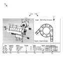
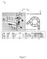
- FIG. 7is a graphical and textual depiction of one example of a collaborative CAx user interface 700 that is consistent with one or more embodiments of the claimed invention.
- the user interface 700includes a graphical rendering 710 with editing regions 720 and a concurrent user list 730 .
- the user interface 700facilitates collaborative user editing of electronic models of engineering objects.
- the graphical rendering 710provides a graphical rendering of an engineering object and/or layer associated therewith.
- the graphical renderingmay be a 2D or 3D rendering from a variety of perspectives that facilitates editing.
- the graphical renderingincludes a perspective CAD rendering 710 a and a cross-sectional analysis rendering 710 b for a region assigned to the user of the interface 700 (i.e. ‘Joe’).
- the editing regions 720may be demarcated with boundaries 722 and marked with user identifiers 724 that indicate generally the extents of the region and which user the region has been assigned to. Although the depicted extents do not overlap each other, the spatial decomposition process may result in distinct regions whose extents do overlap.
- An editing regionmay also be spatially disjoint. For example, an electronic model for an airplane may be partitioned into a cabin interior region, a fuselage exterior region, and a region for the aircraft wings. In some embodiments, graphical renderings within each region are color coded or coded in some other way such as a shading pattern to indicate which user they are assigned to.
- a layer selector 712e.g. a drop-down list
- a collaborative userto select the layer that is to be edited or viewed for an assigned editing region.
- Software tools that are specific to the selected layermay be made available or activated on the user interface 700 in response to layer selection. Examples of such software tools include visualization tools, design tools, meshing tools, simulation tools, analysis tools, manufacture planning tools, and manufacture simulation tools.
- the concurrent user list 730may provide a variety of information relative to collaborative editing such as user names 731 and locations 732 , a region name 733 , a user priority 734 , a region status 735 , a layer indicator 736 , and a channel indicator/selector 737 .
- the user names 731may correspond to a particular user identifier 724 .
- the location 732may indicate the physical location of the user and thereby enhance coordination and communication.
- the region name 733may be derived from information within the electronic model or specified by a user upon assignment or selection.
- the user priority 734may be used to determine which user a region should be assigned to if multiple users attempt to edit the same region. In one embodiment, a higher priority user can assume control of an editing region assigned to a lower priority user.
- the region status 735may indicate the status of editing or analysis for the region such as a ‘pending’ indicator 735 a and a ‘completed’ indicator 735 b .
- the layer indicator 736may indicate the layer that the user is currently editing.
- the channel indicator/selector 737may provide a visual indication of which communication channels are available for communication with each user and enable selection of particular channels for use in communicating with one or more users.
- the various interface elements of the collaborative user interface 700function cooperatively to facilitate productive collaborative editing of electronic models of engineering objects.
- the proceeding depiction of the collaborative user interface 700 and other inventive elements described hereinare intended to be illustrative rather than definitive.
- the claimed inventionmay be embodied in other specific forms without departing from its spirit or essential characteristics.
- the described embodimentsare to be considered in all respects only as illustrative and not restrictive.
- the scope of the inventionis, therefore, indicated by the appended claims rather than by the foregoing description. All changes which come within the meaning and range of equivalency of the claims are to be embraced within their scope.
Landscapes
- Engineering & Computer Science (AREA)
- Physics & Mathematics (AREA)
- Theoretical Computer Science (AREA)
- Computer Hardware Design (AREA)
- Evolutionary Computation (AREA)
- Geometry (AREA)
- General Engineering & Computer Science (AREA)
- General Physics & Mathematics (AREA)
- Stored Programmes (AREA)
- Architecture (AREA)
- Software Systems (AREA)
Abstract
Description
Claims (33)
Priority Applications (1)
| Application Number | Priority Date | Filing Date | Title |
|---|---|---|---|
| US13/156,453US9122817B2 (en) | 2011-06-09 | 2011-06-09 | Collaborative CAx apparatus and method |
Applications Claiming Priority (1)
| Application Number | Priority Date | Filing Date | Title |
|---|---|---|---|
| US13/156,453US9122817B2 (en) | 2011-06-09 | 2011-06-09 | Collaborative CAx apparatus and method |
Publications (2)
| Publication Number | Publication Date |
|---|---|
| US20120317497A1 US20120317497A1 (en) | 2012-12-13 |
| US9122817B2true US9122817B2 (en) | 2015-09-01 |
Family
ID=47294219
Family Applications (1)
| Application Number | Title | Priority Date | Filing Date |
|---|---|---|---|
| US13/156,453Expired - Fee RelatedUS9122817B2 (en) | 2011-06-09 | 2011-06-09 | Collaborative CAx apparatus and method |
Country Status (1)
| Country | Link |
|---|---|
| US (1) | US9122817B2 (en) |
Cited By (5)
| Publication number | Priority date | Publication date | Assignee | Title |
|---|---|---|---|---|
| US20150347567A1 (en)* | 2014-05-28 | 2015-12-03 | Siemens Product Lifecycle Management Software Inc. | Method for creation and editing of a massive constraint network |
| US9965572B1 (en)* | 2015-01-14 | 2018-05-08 | United Technologies Corporation | Multi-user CAx assembly updater |
| US10261756B2 (en)* | 2015-06-01 | 2019-04-16 | Brigham Young University | Method for preventing reference invalidation when reversing operations in synchronous collaborative applications |
| US10366099B1 (en)* | 2014-02-11 | 2019-07-30 | United Technologies Corporation | Reader for multi-user CAx entities created outside of database |
| US10503721B2 (en) | 2014-02-11 | 2019-12-10 | United Technologies Corporation | Conflict resolution for a multi-user CAx environment |
Families Citing this family (22)
| Publication number | Priority date | Publication date | Assignee | Title |
|---|---|---|---|---|
| US9298834B2 (en)* | 2009-05-26 | 2016-03-29 | Adobe Systems Incorporated | User presence data for web-based document collaboration |
| US10242430B2 (en)* | 2012-03-08 | 2019-03-26 | Brigham Young University | Graphical interface for collaborative editing of design space models |
| US10346568B2 (en)* | 2012-10-06 | 2019-07-09 | Brigham Young University | Multi-user finite analysis systems apparatuses and methods |
| EP2923284A4 (en)* | 2012-11-23 | 2016-07-13 | Univ Brigham Young | SYSTEM, METHOD AND APPARATUS FOR COLLABORATIVE CAX EDITING |
| KR20150118975A (en) | 2013-02-05 | 2015-10-23 | 브라이엄 영 유니버시티 | System and methods for multi-user cax editing conflict management |
| WO2014130735A1 (en)* | 2013-02-20 | 2014-08-28 | Brigham Young University | System and methods for multi-user cax editing data consistency |
| US10614180B2 (en) | 2013-04-02 | 2020-04-07 | Brigham Young University | System and method for concurrent multi-user CAx workflow |
| US10108774B2 (en)* | 2013-04-25 | 2018-10-23 | Brigham Young University | Method and apparatus for concurrent multi-user toolpath creation |
| US9996642B2 (en)* | 2013-09-19 | 2018-06-12 | Brigham Young University | Method and apparatus for finite analysis pre-processing |
| US20150199454A1 (en)* | 2014-01-10 | 2015-07-16 | Brigham Young University | Concurrent design and analysis of an engineering object |
| US10366178B2 (en) | 2014-01-27 | 2019-07-30 | Brigham Young University | Multi-user CAx editing of a model of a design object |
| US9871796B1 (en)* | 2014-02-11 | 2018-01-16 | United Technologies Corporation | Multi level decomposition for multi user CAx databases |
| US9983854B2 (en)* | 2014-04-21 | 2018-05-29 | LogMeln, Inc. | Managing and synchronizing views in multi-user application with a canvas |
| US9606526B2 (en)* | 2014-05-28 | 2017-03-28 | Siemens Product Lifecycle Management Software Inc. | Intelligent constraint selection for positioning tasks |
| US10621288B2 (en)* | 2014-06-12 | 2020-04-14 | Brigham Young Unversity | Interoperable hierarchical model for conducting multiuser CAx operations |
| US10114615B1 (en)* | 2014-12-16 | 2018-10-30 | United Technologies Corporation | Feature based control system for multi-user CAx |
| US11080940B1 (en)* | 2014-12-22 | 2021-08-03 | Raytheon Technologies Corporation | Export decomposition filter for a multi-user CAx environment |
| US9904518B1 (en)* | 2015-01-16 | 2018-02-27 | United Technologies Corporation | Support of undeveloped features in multi-user CAx environment |
| US9886230B2 (en) | 2015-06-07 | 2018-02-06 | Apple Inc. | Device, method, and graphical user interface for collaborative editing in documents |
| US10706020B2 (en)* | 2016-04-14 | 2020-07-07 | Brigham Young University | Data sharing in CAx applications |
| US10437239B2 (en)* | 2016-06-13 | 2019-10-08 | Brigham Young University | Operation serialization in a parallel workflow environment |
| US11221994B2 (en) | 2019-07-01 | 2022-01-11 | International Business Machines Corporation | Controlling document edits in a collaborative environment |
Citations (20)
| Publication number | Priority date | Publication date | Assignee | Title |
|---|---|---|---|---|
| US20040085354A1 (en)* | 2002-10-31 | 2004-05-06 | Deepak Massand | Collaborative document development and review system |
| US6877027B1 (en) | 2000-02-19 | 2005-04-05 | Hewlett-Packard Development Company, L.P. | System and method for providing synchronization verification of multiple applications across remote systems |
| US20050165859A1 (en) | 2004-01-15 | 2005-07-28 | Werner Geyer | Method and apparatus for persistent real-time collaboration |
| US20060023969A1 (en)* | 2004-04-30 | 2006-02-02 | Lara Eyal D | Collaboration and multimedia authoring |
| US20060250418A1 (en) | 2001-03-23 | 2006-11-09 | Dassault Corporation | Collaborative design |
| US20060265496A1 (en) | 2000-08-25 | 2006-11-23 | Stefan Freitag | CAD system |
| US7143136B1 (en) | 2002-06-06 | 2006-11-28 | Cadence Design Systems, Inc. | Secure inter-company collaboration environment |
| US20070091119A1 (en)* | 2005-10-24 | 2007-04-26 | Matthew Jezyk | Integrated massing and design CAD models |
| US20070208994A1 (en)* | 2006-03-03 | 2007-09-06 | Reddel Frederick A V | Systems and methods for document annotation |
| US20080046828A1 (en)* | 2001-10-18 | 2008-02-21 | Autodesk, Inc. | Collaboration framework |
| US7546360B2 (en) | 2002-06-06 | 2009-06-09 | Cadence Design Systems, Inc. | Isolated working chamber associated with a secure inter-company collaboration environment |
| US20090199090A1 (en)* | 2007-11-23 | 2009-08-06 | Timothy Poston | Method and system for digital file flow management |
| US20100083136A1 (en)* | 2008-09-29 | 2010-04-01 | International Business Machines Corporation | Joint editing of an on-line document |
| US20100121614A1 (en)* | 2007-05-01 | 2010-05-13 | M.E.P. Cad, Inc. | Methods and Apparatuses for Preprocessing a CAD Drawing |
| US7818679B2 (en) | 2004-04-20 | 2010-10-19 | Microsoft Corporation | Method, system, and apparatus for enabling near real time collaboration on an electronic document through a plurality of computer systems |
| US20110119638A1 (en)* | 2009-11-17 | 2011-05-19 | Babak Forutanpour | User interface methods and systems for providing gesturing on projected images |
| US20110126099A1 (en)* | 2009-11-25 | 2011-05-26 | Novell, Inc. | System and method for recording collaborative information technology processes in an intelligent workload management system |
| US20110145760A1 (en)* | 2009-12-15 | 2011-06-16 | Dassault Systemes | Method and system for editing a product assembly |
| US8327278B2 (en)* | 2009-02-17 | 2012-12-04 | Microsoft Corporation | Synchronizing metadata describes user content updates and an indication of user gestures being performed within the document, and across client systems using different communication channels |
| US8762941B2 (en)* | 2006-02-16 | 2014-06-24 | Dirtt Environmental Solutions, Ltd. | Rendering and modifying CAD design entities in object-oriented applications |
- 2011
- 2011-06-09USUS13/156,453patent/US9122817B2/ennot_activeExpired - Fee Related
Patent Citations (22)
| Publication number | Priority date | Publication date | Assignee | Title |
|---|---|---|---|---|
| US6877027B1 (en) | 2000-02-19 | 2005-04-05 | Hewlett-Packard Development Company, L.P. | System and method for providing synchronization verification of multiple applications across remote systems |
| US20060265496A1 (en) | 2000-08-25 | 2006-11-23 | Stefan Freitag | CAD system |
| US20060250418A1 (en) | 2001-03-23 | 2006-11-09 | Dassault Corporation | Collaborative design |
| US7176942B2 (en) | 2001-03-23 | 2007-02-13 | Dassault Systemes | Collaborative design |
| US20080046828A1 (en)* | 2001-10-18 | 2008-02-21 | Autodesk, Inc. | Collaboration framework |
| US7143136B1 (en) | 2002-06-06 | 2006-11-28 | Cadence Design Systems, Inc. | Secure inter-company collaboration environment |
| US7546360B2 (en) | 2002-06-06 | 2009-06-09 | Cadence Design Systems, Inc. | Isolated working chamber associated with a secure inter-company collaboration environment |
| US20040085354A1 (en)* | 2002-10-31 | 2004-05-06 | Deepak Massand | Collaborative document development and review system |
| US20050165859A1 (en) | 2004-01-15 | 2005-07-28 | Werner Geyer | Method and apparatus for persistent real-time collaboration |
| US7840596B2 (en) | 2004-01-15 | 2010-11-23 | International Business Machines Corporation | Method and apparatus for persistent real-time collaboration |
| US7818679B2 (en) | 2004-04-20 | 2010-10-19 | Microsoft Corporation | Method, system, and apparatus for enabling near real time collaboration on an electronic document through a plurality of computer systems |
| US20060023969A1 (en)* | 2004-04-30 | 2006-02-02 | Lara Eyal D | Collaboration and multimedia authoring |
| US20070091119A1 (en)* | 2005-10-24 | 2007-04-26 | Matthew Jezyk | Integrated massing and design CAD models |
| US8762941B2 (en)* | 2006-02-16 | 2014-06-24 | Dirtt Environmental Solutions, Ltd. | Rendering and modifying CAD design entities in object-oriented applications |
| US20070208994A1 (en)* | 2006-03-03 | 2007-09-06 | Reddel Frederick A V | Systems and methods for document annotation |
| US20100121614A1 (en)* | 2007-05-01 | 2010-05-13 | M.E.P. Cad, Inc. | Methods and Apparatuses for Preprocessing a CAD Drawing |
| US20090199090A1 (en)* | 2007-11-23 | 2009-08-06 | Timothy Poston | Method and system for digital file flow management |
| US20100083136A1 (en)* | 2008-09-29 | 2010-04-01 | International Business Machines Corporation | Joint editing of an on-line document |
| US8327278B2 (en)* | 2009-02-17 | 2012-12-04 | Microsoft Corporation | Synchronizing metadata describes user content updates and an indication of user gestures being performed within the document, and across client systems using different communication channels |
| US20110119638A1 (en)* | 2009-11-17 | 2011-05-19 | Babak Forutanpour | User interface methods and systems for providing gesturing on projected images |
| US20110126099A1 (en)* | 2009-11-25 | 2011-05-26 | Novell, Inc. | System and method for recording collaborative information technology processes in an intelligent workload management system |
| US20110145760A1 (en)* | 2009-12-15 | 2011-06-16 | Dassault Systemes | Method and system for editing a product assembly |
Non-Patent Citations (19)
| Title |
|---|
| B. Xu, Q. Gao, and C. Li, Reusing Single-User Applications to Create Collaborative Multi-Member Applications, Advances in Engineering Software, vol. 40, Issue 8, Aug. 2009, pp. 618-622. |
| C.M. Hoffmann and R. Juan, Erep, An Editable, High-Level Representation for Geometric Design and Analysis. In: P Wilson, M Wozny and MJ Pratt, Editors, Geometric and Product Modelling, North Holland (1993), pp. 129-164. |
| Caligari Truespace 7.5 Website window (2011). |
| D. Janaki Ram, Vivekananda, Ch. S. Rao and K. Mohan, Constraint Meta-object: a New Object Model for Distributed Collaborative Designing, IEEE Transactions on Systems, Man and Cybernetics (Part A), 27(2), 208-221 (Mar. 1997). |
| D.Y. Zhang, L. Wang, Y. Zeng. Secure Collaborative Product Development: a Literature Review. International Conference on Product Lifecycle Management. Proc. 5th International Conference on Product Lifecycle Management (PLM 2008), Jul. 9-11, 2008. |
| Fahdah, I. And Tizani, W., 2008. "Communication and Concurrency Approach for a Real-time Collaborative Building Design Environment" in: Rafiq, Y., De Wilde, P. And Borthwick, M., eds., Intelligent Computing in Engineering: Conference Proceedings 2008 University of Plymouth., pp. 283-291. |
| G. Wallace et al., A Multicursor X Window Manager Supporting Control Room Collaboration, tech. report TR-707-04, Dept. of Computer Science, Princeton Univ., 2004. |
| J. Y. H. Fuh/W. D. Li, Advances in Collaborative CAD: The State of the Art, Computer-Aided Design, 2005, 571-581, 37(5), Singapore/Singapore. |
| L. Shen, Y. Hao, M. Li, W. Zhao, J. Zheng. A Synchronous Collaborative Environment for Engineering Design Education. Proceedings of the 2007 11th International Conference on Computer Supported Cooperative Work in Design. |
| M. Li, S. Gao, C.C.L. Wang. Real-Time Collaborative Design With Heterogeneous CAD Systems Based on Neutral Modeling Commands. Journal of Computing and Information Science in Engineering June 2007, vol. 7 / 113. |
| M. Sharma, V. Raja, T. Fernando. Collaborative Design Review in a Distributed Environment. Intelligent Production Machines and Systems. D.T. Pham, E.E. Eldukhri, and A.J. Soroka (eds). Cardiff University (2006). |
| Meng, X, Liu, X, and Xu, Y, "Real-Time Collaborative Design System for Product Assembly Over the Internet", IFIP International Federation for Information Processing, 2006, vol. 220, Information Technology for Balanced Manufacturing Systems ed. Shen, W., (Boston; Spring), pp. 253-260. |
| Michael Ryba/Utz Baitinger, An Integrated Concept for Design Project Planning and Design Flow Control, EURO-DAC '96/EURO-VHDL'96 Proceedings of the Conference in European Design Automation, 1996, 98-103, Stuttgart/Germany. |
| Min Li/ Shuming Gao/Charlie C. L. Wang, Real Time Collaborative Design with Heterogenous CAD Systems Based on Neutral Modeling Commands, Journal of Computing and Information Science in Engineering. 2007, 113-125, vol. 7, Singapore/Singapore. |
| O. Matviykiv, M. Lobur, O. Lebedeva. Virtual Collaborative Design Environment for Distributed CAD Systems. CADSM'2007, Feb. 20-24, 2007, Polyana, Ukraine. |
| R.K. Thomas and R.S. Sandhu. Task-based Authorization Controls (TBAC): A Family of Models for Active and Enterprise-oriented Authorization Management. Proceedings of the IFIP WG11.3 Workshop on Database Security, Lake Tahoe, California, Aug. 11-13, 1997. |
| S. Jing, F. He, S Han, X Cai, H Lui. A Method for Topological Entity Correspondence in a Replicated Collaborative CAD System. Computers in Industry. to appearing, article in press, available online Mar. 17, 2009. |
| S. Wei, M. M Tiegiang, L. Tao. Constraint Conversion Method in Feature-Based Heterogenous CAD Model Exchange. Information Technology Journal (2008). |
| T. Kim, C. Cera, W. Regli, H. Choo, J. Han. Multi-Level modeling and access control for data sharing in collaborative design. Advanced Engineering Informatics 20 (2006) 47-57. |
Cited By (5)
| Publication number | Priority date | Publication date | Assignee | Title |
|---|---|---|---|---|
| US10366099B1 (en)* | 2014-02-11 | 2019-07-30 | United Technologies Corporation | Reader for multi-user CAx entities created outside of database |
| US10503721B2 (en) | 2014-02-11 | 2019-12-10 | United Technologies Corporation | Conflict resolution for a multi-user CAx environment |
| US20150347567A1 (en)* | 2014-05-28 | 2015-12-03 | Siemens Product Lifecycle Management Software Inc. | Method for creation and editing of a massive constraint network |
| US9965572B1 (en)* | 2015-01-14 | 2018-05-08 | United Technologies Corporation | Multi-user CAx assembly updater |
| US10261756B2 (en)* | 2015-06-01 | 2019-04-16 | Brigham Young University | Method for preventing reference invalidation when reversing operations in synchronous collaborative applications |
Also Published As
| Publication number | Publication date |
|---|---|
| US20120317497A1 (en) | 2012-12-13 |
Similar Documents
| Publication | Publication Date | Title |
|---|---|---|
| US9122817B2 (en) | Collaborative CAx apparatus and method | |
| US10140402B2 (en) | Parallel workflow finite element pre-processing apparatus and system | |
| US9779184B2 (en) | Scalable multi-user CAD system and apparatus | |
| US10242430B2 (en) | Graphical interface for collaborative editing of design space models | |
| US9648059B2 (en) | System and methods for multi-user CAx editing conflict management | |
| US8983982B2 (en) | Mechanism for deprecating object oriented data | |
| US10706020B2 (en) | Data sharing in CAx applications | |
| US20160098494A1 (en) | Integration of analysis with multi-user cad | |
| US20160021183A1 (en) | Collaborative cax updates | |
| Shunk et al. | The application of an integrated enterprise modeling methodology—FIDO—to supply chain integration modeling | |
| US10346568B2 (en) | Multi-user finite analysis systems apparatuses and methods | |
| US20160162607A1 (en) | Model for Managing Variations in a Product Structure for a Product | |
| CN110532640B (en) | Digital Prototype Collaborative System for Physical Products and Its Construction Method | |
| US11157273B2 (en) | Scaled agile framework program board | |
| US10140387B2 (en) | Model for managing variations in a product structure for a product | |
| CN119025074A (en) | A structured management method for agile business architecture system | |
| EP2698734A2 (en) | Model for managing variations in a product structure for a product | |
| EP2823421B1 (en) | Multi-user decomposition of design space models | |
| EP3206143A1 (en) | System and method for managing variations in a product structure for a product | |
| US20170337296A1 (en) | Data protection in cax applications | |
| US20170076242A1 (en) | Work management with claims/priority assignment and dynamic work allocation | |
| US10318673B2 (en) | Multi-user CAx assembly load time reduction while maintaining inter-part consistency | |
| WO2014142990A1 (en) | Scalable multi-user cad system and apparatus | |
| US20140365989A1 (en) | Information product builder, production and delivery system | |
| US20150271221A1 (en) | Selection triggered collaborative cax editing |
Legal Events
| Date | Code | Title | Description |
|---|---|---|---|
| AS | Assignment | Owner name:BRIGHAM YOUNG UNIVERSITY, UTAH Free format text:ASSIGNMENT OF ASSIGNORS INTEREST;ASSIGNORS:RED, WALTER EDWARD;JENSEN, CHARLES GREGORY;RYSKAMP, JORDAN DAVID;REEL/FRAME:026414/0702 Effective date:20110608 | |
| STCF | Information on status: patent grant | Free format text:PATENTED CASE | |
| MAFP | Maintenance fee payment | Free format text:PAYMENT OF MAINTENANCE FEE, 4TH YR, SMALL ENTITY (ORIGINAL EVENT CODE: M2551); ENTITY STATUS OF PATENT OWNER: SMALL ENTITY Year of fee payment:4 | |
| AS | Assignment | Owner name:COLLAB SYSTEMS LLC, DELAWARE Free format text:ASSIGNMENT OF ASSIGNORS INTEREST;ASSIGNOR:BRIGHAM YOUNG UNIVERSITY;REEL/FRAME:056983/0713 Effective date:20210727 | |
| FEPP | Fee payment procedure | Free format text:MAINTENANCE FEE REMINDER MAILED (ORIGINAL EVENT CODE: REM.); ENTITY STATUS OF PATENT OWNER: SMALL ENTITY | |
| LAPS | Lapse for failure to pay maintenance fees | Free format text:PATENT EXPIRED FOR FAILURE TO PAY MAINTENANCE FEES (ORIGINAL EVENT CODE: EXP.); ENTITY STATUS OF PATENT OWNER: SMALL ENTITY | |
| STCH | Information on status: patent discontinuation | Free format text:PATENT EXPIRED DUE TO NONPAYMENT OF MAINTENANCE FEES UNDER 37 CFR 1.362 | |
| FP | Lapsed due to failure to pay maintenance fee | Effective date:20230901 | |
| AS | Assignment | Owner name:BRIGHAM YOUNG UNIVERSITY, UTAH Free format text:ASSIGNMENT OF ASSIGNORS INTEREST;ASSIGNOR:COLLAB SYSTEMS LLC;REEL/FRAME:070953/0618 Effective date:20250424 |