US9121279B2 - Tunable transition duct side seals in a gas turbine engine - Google Patents
Tunable transition duct side seals in a gas turbine engineDownload PDFInfo
- Publication number
- US9121279B2 US9121279B2US12/901,084US90108410AUS9121279B2US 9121279 B2US9121279 B2US 9121279B2US 90108410 AUS90108410 AUS 90108410AUS 9121279 B2US9121279 B2US 9121279B2
- Authority
- US
- United States
- Prior art keywords
- combustion system
- seals
- gas turbine
- combustion
- openings
- Prior art date
- Legal status (The legal status is an assumption and is not a legal conclusion. Google has not performed a legal analysis and makes no representation as to the accuracy of the status listed.)
- Active, expires
Links
Images


Classifications
- F—MECHANICAL ENGINEERING; LIGHTING; HEATING; WEAPONS; BLASTING
- F01—MACHINES OR ENGINES IN GENERAL; ENGINE PLANTS IN GENERAL; STEAM ENGINES
- F01D—NON-POSITIVE DISPLACEMENT MACHINES OR ENGINES, e.g. STEAM TURBINES
- F01D9/00—Stators
- F01D9/02—Nozzles; Nozzle boxes; Stator blades; Guide conduits, e.g. individual nozzles
- F01D9/023—Transition ducts between combustor cans and first stage of the turbine in gas-turbine engines; their cooling or sealings
- F—MECHANICAL ENGINEERING; LIGHTING; HEATING; WEAPONS; BLASTING
- F23—COMBUSTION APPARATUS; COMBUSTION PROCESSES
- F23R—GENERATING COMBUSTION PRODUCTS OF HIGH PRESSURE OR HIGH VELOCITY, e.g. GAS-TURBINE COMBUSTION CHAMBERS
- F23R3/00—Continuous combustion chambers using liquid or gaseous fuel
- F23R3/02—Continuous combustion chambers using liquid or gaseous fuel characterised by the air-flow or gas-flow configuration
- F23R3/26—Controlling the air flow
- F—MECHANICAL ENGINEERING; LIGHTING; HEATING; WEAPONS; BLASTING
- F01—MACHINES OR ENGINES IN GENERAL; ENGINE PLANTS IN GENERAL; STEAM ENGINES
- F01D—NON-POSITIVE DISPLACEMENT MACHINES OR ENGINES, e.g. STEAM TURBINES
- F01D11/00—Preventing or minimising internal leakage of working-fluid, e.g. between stages
- F01D11/005—Sealing means between non relatively rotating elements
- F—MECHANICAL ENGINEERING; LIGHTING; HEATING; WEAPONS; BLASTING
- F23—COMBUSTION APPARATUS; COMBUSTION PROCESSES
- F23R—GENERATING COMBUSTION PRODUCTS OF HIGH PRESSURE OR HIGH VELOCITY, e.g. GAS-TURBINE COMBUSTION CHAMBERS
- F23R2900/00—Special features of, or arrangements for continuous combustion chambers; Combustion processes therefor
- F23R2900/00012—Details of sealing devices
- F—MECHANICAL ENGINEERING; LIGHTING; HEATING; WEAPONS; BLASTING
- F23—COMBUSTION APPARATUS; COMBUSTION PROCESSES
- F23R—GENERATING COMBUSTION PRODUCTS OF HIGH PRESSURE OR HIGH VELOCITY, e.g. GAS-TURBINE COMBUSTION CHAMBERS
- F23R3/00—Continuous combustion chambers using liquid or gaseous fuel
- F23R3/02—Continuous combustion chambers using liquid or gaseous fuel characterised by the air-flow or gas-flow configuration
Definitions
- the present inventiongenerally relates to gas turbine engines. More particularly, embodiments of the present invention relate to a combustion system and a method of operation of the combustion system in order to provide an additional way of controlling engine emissions and combustion dynamics.
- Gas turbine enginesoperate to produce mechanical work or thrust.
- a generatoris typically coupled to the shaft, such that the mechanical work produced is harnessed to generate electricity.
- a typical gas turbine enginecomprises a compressor, at least one combustor, and a turbine, with the compressor and turbine coupled together through an axial shaft.
- airpasses through the compressor, where the pressure of the air increases and then passes to a combustion section, where fuel is mixed with the compressed air in one or more combustion chambers.
- the hot combustion gasesthen pass into the turbine and drive the turbine.
- the compressorturns, since they are coupled together along a common shaft.
- the turning of the shaftalso drives the generator for electrical applications.
- the gas turbine enginealso must operate within the confines of the environmental regulations for the area in which the engine is located. As a result, more advanced combustion systems have been developed to more efficiently mix fuel and air so as to provide more complete combustion, which results in lower emissions.
- Low emissions combustion systemsrequire the fuel and air being mixed to be properly proportioned in order to obtain optimal results.
- Fuel flowsare usually tightly controlled through carefully sized orifices in the fuel nozzles and controlled fuel valves. Airflows may actually vary due to distributions driven by the compressor exit profile and the amount of air required to cool the turbine section. Because the amount of air introduced into the combustion system significantly affects reaction zone temperature and performance of the combustion system, an adjustable air mass is advantageous for regulating the combustion process.
- LBOlean blow out
- Another known problem of tuning a gas turbine combustorinclude excessive combustion dynamics caused by rapid changes in pressures within the combustor.
- prior gas turbine combustorsincorporated additional dilution holes in the combustion liner or a transition piece in order to control the amount of air being used in the combustion process.
- these forms of “air control”have been known to adversely effect emissions of the combustion system, at least with respect to carbon monoxide.
- Embodiments of the present inventionare directed towards a system and method for, among other things, tuning a gas turbine engine to avoid operational and emissions issues found in prior art designs.
- a gas turbine combustion systemcomprises a combustion liner, a flow sleeve encompassing the combustion liner, an end cap positioned near an end of the combustion liner and the flow sleeve.
- a plurality of fuel nozzlesextend through the cap and towards the combustion liner.
- a transition ductcouples the aft end of the combustion liner to an inlet of the turbine in order to direct the flow of hot combustion gases from the combustor to the turbine.
- a plurality of tunable side sealsare positioned between adjacent transition ducts and the inlet of the turbine. The plurality of side seals each have one or more openings located therein that permit a controlled amount of air to pass therethrough and bypass the combustion system.
- a method of tuning a combustion system of a gas turbine engineis disclosed.
- a portion of an airflow source to be supplied to the combustion systemis determined and then, a size and quantity of openings for a plurality of seals is determined in which the size and quantity will result in the portion of an airflow source being supplied to the combustion system by permitting the remainder of the airflow source to bypass the combustion system.
- the openingsare placed in the plurality of seals and the seals are then placed in the gas turbine engine to regulate the amount of airflow permitted to bypass the combustion system.
- a tunable side seal for use in a gas turbine combustorwherein the seal comprises one or more sheets of material secured together having one or more holes located through the one or more sheets.
- the sealis sized and configured to be positioned between sidewalls of adjacent transition ducts and a turbine inlet. Furthermore, the seals are oriented in a manner so as to be accessible from outside of a gas turbine engine such that the seal can be removed and the one or more holes altered to adjust the amount of air permitted to pass therethrough.
- FIG. 1depicts a perspective view of a portion of a gas turbine engine of the prior art
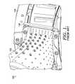
- FIG. 2depicts a perspective view of a portion of a gas turbine engine in accordance with an embodiment of the present invention
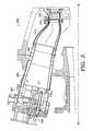
- FIG. 3depicts a cross section of a gas turbine engine in accordance with an embodiment of the present invention
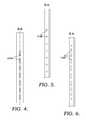
- FIG. 4depicts an elevation view of a seal used in an embodiment of the present invention
- FIG. 5depicts an elevation view of an alternate seal in an embodiment of the present invention
- FIG. 6depicts an elevation view of yet another seal in an embodiment of the present invention.
- FIG. 7is a chart identifying a method of tuning a combustion system of a gas turbine engine in accordance with an embodiment of the present invention.
- the combustion system 100includes a plurality of combustion liners (not shown) with each liner coupled to a transition duct 102 and the transition duct 102 is in turn coupled to the turbine inlet 104 .
- Transition ducts 102direct the flow of hot combustion gases from a combustion liner to the turbine inlet 104 .
- Prior art combustorsattempted to direct all of the air from the compressor (except for that used for turbine cooling) to the combustion system 100 for maximum efficiency by placing solid seals 106 between adjacent transition ducts 102 and the turbine inlet 106 .
- a gas turbine operator or manufacturercould place or adjust size and location of dilution holes in the combustion liner or transition duct 102 in an effort to tailor the airflow to the combustion system.
- such effortsaffected the combustion system emissions as well as the temperature profile entering the turbine.
- the use of solid seals 106has also resulted in too much air being provided to the combustion system, resulting in an overly lean fuel-air mixture.
- FIG. 2depicts a portion of a gas turbine combustion system 200 having a tunable side seal 202 , where the seal 202 is shown in greater detail in FIGS. 4-6 .
- a tunable gas turbine combustion system 200comprises a combustion liner 204 , a flow sleeve 206 encompassing the combustion liner 204 and an end cap 208 positioned proximate a forward end of the combustion liner 204 and flow sleeve 206 .
- a plurality of fuel nozzles 210extend through openings in the end cap 208 with the fuel nozzles 210 extending towards the combustion liner 204 .
- a transition duct 212that directs the hot combustion gases from the combustion liner 204 into a turbine inlet 214 .
- a double-walled transition ductis utilized.
- a plurality of tunable side seals 202are located adjacent to the transition duct 204 and have one or more openings 218 located therein.
- the openings 218 Aaid in tuning the combustion system 200 by permitting a predetermined amount of air to pass therethrough.
- a controlled portion of airbypasses the combustion system 200 , including the combustion liner 204 and transition duct 212 .
- Directing a predetermined amount of air through the side seals 202provides the operator with a way of tuning the combustion system 200 by setting a quantity and size of openings 218 A which will regulate the amount of air directed to the combustion system 200 .
- the combustion system 200is generally a can-annular system where there are a plurality of individual combustion systems arranged about a centerline or longitudinal axis of a gas turbine engine as shown in FIG. 3 .
- Each combustion liner 204 and transition duct 212feed hot combustion gases into a portion of the turbine inlet 214 .
- the plurality of side seals 202are oriented generally radially outward relative to the centerline A-A, as shown in FIG. 3 .
- An additional advantage provided by this seal orientationis the ability to remove the plurality of side seals 202 from the combustion system 200 .
- Openings 218 Acan be altered in size and/or quantity if an operator determines the amount of air passing therethrough, and bypassing the combustion system 200 , is either too much or too little. Openings 218 A can be welded closed should there be too much air passing therethrough, or the size of the openings can be increased if the air flow is too little.
- a plurality of side seals 202can be used to regulate the amount of air permitted to bypass the combustion system compatible with a General Electric Frame 7FA gas turbine engine.
- the seal arrangement for this type of combustion systemgenerally permits up to approximately 2% of air from the compressor to bypass the combustion system and pass directly into the turbine.
- the present inventionis not limited to this engine, but instead can be used on a variety of engine types and the total amount of air permitted to pass therethrough can vary.
- the plurality of side seals 202can be fabricated from a variety of materials and sizes depending upon the size and shape of slots between the transition duct 212 and turbine inlet 214 and the operating conditions. Because of the elevated operating temperatures, the plurality of seals 202 are generally fabricated from a high temperature cobalt-based alloy such as Haynes 188 . In an embodiment of the invention, the plurality of seals 202 are each generally fabricated from sheet metal, including an embodiment in which a plurality of sheets of metal are fixed together by brazing or a series of spot welds, such that the seal is flexible along the seal axis (S-A), as shown in FIG. 4 . Due to the seal construction, the openings should be placed in areas absent of a weld or braze material so as to not initiate cracks in the joints between sheets of metal forming the seal.
- a tunable side seal 202 in a gas turbine combustion systemis disclosed.
- the tunable side seal 202is fabricated from one or more sheets of material 220 having one or more openings or holes located through the one or more sheets.
- the side seal 202can be fabricated from a cobalt-based alloy.
- the tunable side seal 202is sized to be positioned between sidewalls (e.g. 232 and 234 of FIG. 2 ) of adjacent transition ducts 212 and the turbine inlet 214 , as shown in FIG. 4 .
- the exact size of the seals and their thicknessdepends on the configuration of the slot. However, slightly undersizing the thickness of the seal 202 compared to the slot will aid in permitting the seal 202 to be removed.
- seal 202is fabricated from a plurality of sheets of metal that are fixed together along a seal centerline SC, the seal is flexible about its centerline. This flexibility also aids in the installation and removal of the seals 202 when the openings are to be adjusted.
- the plurality of seals 202each has a plurality of openings or holes.
- the openingscan be a variety of shapes and sizes depending upon the amount of air desired to pass through the seal.
- Such a cooling schemecan be created by a uniform set of elliptically-shaped holes 218 A as shown in FIG. 4 , a set of circular holes 218 B as shown in FIG. 5 , or a varying pattern of holes 218 C across the seal as shown in FIG. 6 as long as the total flow permitted to pass through each seal is generally equal around the turbine inlet 214 .
- An additional alternate embodiment of the present inventiondiscloses a method 700 of tuning a combustion system of a gas turbine engine, and is shown in FIG. 7 .
- the method 700comprises a step 702 of determining a portion of an airflow source that is to be supplied to the combustion system. Then, in a step 704 , the size and quantity of openings for the plurality of seals that will result in the desired portion of the airflow source to be supplied to the combustion system is determined. Then, in a step 706 the holes are placed in the plurality of seals, and then in a step 708 , the plurality of seals having the holes are placed into the gas turbine engine in a region between adjacent transition ducts and an inlet of the turbine.
Landscapes
- Engineering & Computer Science (AREA)
- Mechanical Engineering (AREA)
- General Engineering & Computer Science (AREA)
- Chemical & Material Sciences (AREA)
- Combustion & Propulsion (AREA)
- Turbine Rotor Nozzle Sealing (AREA)
Abstract
Description
Claims (5)
Priority Applications (1)
| Application Number | Priority Date | Filing Date | Title |
|---|---|---|---|
| US12/901,084US9121279B2 (en) | 2010-10-08 | 2010-10-08 | Tunable transition duct side seals in a gas turbine engine |
Applications Claiming Priority (1)
| Application Number | Priority Date | Filing Date | Title |
|---|---|---|---|
| US12/901,084US9121279B2 (en) | 2010-10-08 | 2010-10-08 | Tunable transition duct side seals in a gas turbine engine |
Publications (2)
| Publication Number | Publication Date |
|---|---|
| US20120085099A1 US20120085099A1 (en) | 2012-04-12 |
| US9121279B2true US9121279B2 (en) | 2015-09-01 |
Family
ID=45924041
Family Applications (1)
| Application Number | Title | Priority Date | Filing Date |
|---|---|---|---|
| US12/901,084Active2034-03-01US9121279B2 (en) | 2010-10-08 | 2010-10-08 | Tunable transition duct side seals in a gas turbine engine |
Country Status (1)
| Country | Link |
|---|---|
| US (1) | US9121279B2 (en) |
Families Citing this family (3)
| Publication number | Priority date | Publication date | Assignee | Title |
|---|---|---|---|---|
| US20130318986A1 (en)* | 2012-06-05 | 2013-12-05 | General Electric Company | Impingement cooled combustor |
| US9303871B2 (en)* | 2013-06-26 | 2016-04-05 | Siemens Aktiengesellschaft | Combustor assembly including a transition inlet cone in a gas turbine engine |
| WO2017131650A1 (en)* | 2016-01-27 | 2017-08-03 | Siemens Aktiengesellschaft | Transition system side seal for gas turbine engines |
Citations (24)
| Publication number | Priority date | Publication date | Assignee | Title |
|---|---|---|---|---|
| US4719748A (en) | 1985-05-14 | 1988-01-19 | General Electric Company | Impingement cooled transition duct |
| US6209325B1 (en)* | 1996-03-29 | 2001-04-03 | European Gas Turbines Limited | Combustor for gas- or liquid-fueled turbine |
| US6345494B1 (en) | 2000-09-20 | 2002-02-12 | Siemens Westinghouse Power Corporation | Side seal for combustor transitions |
| US6412268B1 (en) | 2000-04-06 | 2002-07-02 | General Electric Company | Cooling air recycling for gas turbine transition duct end frame and related method |
| US20020121744A1 (en)* | 2001-03-05 | 2002-09-05 | General Electric Company | Low leakage flexible cloth seals for turbine combustors |
| US6450762B1 (en)* | 2001-01-31 | 2002-09-17 | General Electric Company | Integral aft seal for turbine applications |
| US6675584B1 (en)* | 2002-08-15 | 2004-01-13 | Power Systems Mfg, Llc | Coated seal article used in turbine engines |
| US6745571B2 (en)* | 2001-07-13 | 2004-06-08 | Pratt & Whitney Canada Corp. | Method of combustor cycle airflow adjustment |
| US6792763B2 (en) | 2002-08-15 | 2004-09-21 | Power Systems Mfg., Llc | Coated seal article with multiple coatings |
| US6834507B2 (en) | 2002-08-15 | 2004-12-28 | Power Systems Mfg., Llc | Convoluted seal with enhanced wear capability |
| US20050166599A1 (en)* | 2003-12-09 | 2005-08-04 | Masao Terazaki | Gas turbine combustion apparatus |
| US7178340B2 (en) | 2003-09-24 | 2007-02-20 | Power Systems Mfg., Llc | Transition duct honeycomb seal |
| US20070175220A1 (en)* | 2006-02-02 | 2007-08-02 | Siemens Power Generation, Inc. | Gas turbine engine curved diffuser with partial impingement cooling apparatus for transitions |
| US7481037B2 (en)* | 2003-07-14 | 2009-01-27 | Mitsubishi Heavy Industries, Ltd. | Cooling structure of gas turbine tail pipe |
| US20090072497A1 (en)* | 2005-08-23 | 2009-03-19 | Mitsubishi Heavy Industries Ltd. | Seal structure for gas turbine combustor |
| US7527472B2 (en) | 2006-08-24 | 2009-05-05 | Siemens Energy, Inc. | Thermally sprayed conformal seal |
| US20090145099A1 (en)* | 2007-12-06 | 2009-06-11 | Power Systems Mfg., Llc | Transition duct cooling feed tubes |
| US20090188258A1 (en)* | 2008-01-29 | 2009-07-30 | Alstom Technologies Ltd. Llc | Altering a natural frequency of a gas turbine transition duct |
| US20090324387A1 (en)* | 2008-06-30 | 2009-12-31 | General Electric Company | Aft frame with oval-shaped cooling slots and related method |
| US20100061837A1 (en)* | 2008-09-05 | 2010-03-11 | James Michael Zborovsky | Turbine transition duct apparatus |
| US8186167B2 (en)* | 2008-07-07 | 2012-05-29 | General Electric Company | Combustor transition piece aft end cooling and related method |
| US8245515B2 (en)* | 2008-08-06 | 2012-08-21 | General Electric Company | Transition duct aft end frame cooling and related method |
| US20120280460A1 (en)* | 2011-05-06 | 2012-11-08 | General Electric Company | Two-piece side seal with covers |
| US8562000B2 (en)* | 2011-05-20 | 2013-10-22 | Siemens Energy, Inc. | Turbine combustion system transition piece side seals |
- 2010
- 2010-10-08USUS12/901,084patent/US9121279B2/enactiveActive
Patent Citations (25)
| Publication number | Priority date | Publication date | Assignee | Title |
|---|---|---|---|---|
| US4719748A (en) | 1985-05-14 | 1988-01-19 | General Electric Company | Impingement cooled transition duct |
| US6209325B1 (en)* | 1996-03-29 | 2001-04-03 | European Gas Turbines Limited | Combustor for gas- or liquid-fueled turbine |
| US6412268B1 (en) | 2000-04-06 | 2002-07-02 | General Electric Company | Cooling air recycling for gas turbine transition duct end frame and related method |
| US6345494B1 (en) | 2000-09-20 | 2002-02-12 | Siemens Westinghouse Power Corporation | Side seal for combustor transitions |
| US6450762B1 (en)* | 2001-01-31 | 2002-09-17 | General Electric Company | Integral aft seal for turbine applications |
| US20020121744A1 (en)* | 2001-03-05 | 2002-09-05 | General Electric Company | Low leakage flexible cloth seals for turbine combustors |
| US6745571B2 (en)* | 2001-07-13 | 2004-06-08 | Pratt & Whitney Canada Corp. | Method of combustor cycle airflow adjustment |
| US6675584B1 (en)* | 2002-08-15 | 2004-01-13 | Power Systems Mfg, Llc | Coated seal article used in turbine engines |
| US6792763B2 (en) | 2002-08-15 | 2004-09-21 | Power Systems Mfg., Llc | Coated seal article with multiple coatings |
| US6834507B2 (en) | 2002-08-15 | 2004-12-28 | Power Systems Mfg., Llc | Convoluted seal with enhanced wear capability |
| US7481037B2 (en)* | 2003-07-14 | 2009-01-27 | Mitsubishi Heavy Industries, Ltd. | Cooling structure of gas turbine tail pipe |
| US7178340B2 (en) | 2003-09-24 | 2007-02-20 | Power Systems Mfg., Llc | Transition duct honeycomb seal |
| US20050166599A1 (en)* | 2003-12-09 | 2005-08-04 | Masao Terazaki | Gas turbine combustion apparatus |
| US7788932B2 (en)* | 2005-08-23 | 2010-09-07 | Mitsubishi Heavy Industries, Ltd. | Seal structure for gas turbine combustor |
| US20090072497A1 (en)* | 2005-08-23 | 2009-03-19 | Mitsubishi Heavy Industries Ltd. | Seal structure for gas turbine combustor |
| US20070175220A1 (en)* | 2006-02-02 | 2007-08-02 | Siemens Power Generation, Inc. | Gas turbine engine curved diffuser with partial impingement cooling apparatus for transitions |
| US7527472B2 (en) | 2006-08-24 | 2009-05-05 | Siemens Energy, Inc. | Thermally sprayed conformal seal |
| US20090145099A1 (en)* | 2007-12-06 | 2009-06-11 | Power Systems Mfg., Llc | Transition duct cooling feed tubes |
| US20090188258A1 (en)* | 2008-01-29 | 2009-07-30 | Alstom Technologies Ltd. Llc | Altering a natural frequency of a gas turbine transition duct |
| US20090324387A1 (en)* | 2008-06-30 | 2009-12-31 | General Electric Company | Aft frame with oval-shaped cooling slots and related method |
| US8186167B2 (en)* | 2008-07-07 | 2012-05-29 | General Electric Company | Combustor transition piece aft end cooling and related method |
| US8245515B2 (en)* | 2008-08-06 | 2012-08-21 | General Electric Company | Transition duct aft end frame cooling and related method |
| US20100061837A1 (en)* | 2008-09-05 | 2010-03-11 | James Michael Zborovsky | Turbine transition duct apparatus |
| US20120280460A1 (en)* | 2011-05-06 | 2012-11-08 | General Electric Company | Two-piece side seal with covers |
| US8562000B2 (en)* | 2011-05-20 | 2013-10-22 | Siemens Energy, Inc. | Turbine combustion system transition piece side seals |
Also Published As
| Publication number | Publication date |
|---|---|
| US20120085099A1 (en) | 2012-04-12 |
Similar Documents
| Publication | Publication Date | Title |
|---|---|---|
| US9163837B2 (en) | Flow conditioner in a combustor of a gas turbine engine | |
| EP2282119B1 (en) | Combustion liner cap assembly for combustion dynamics reduction | |
| US10041676B2 (en) | Sealed conical-flat dome for flight engine combustors | |
| US7269957B2 (en) | Combustion liner having improved cooling and sealing | |
| US7574865B2 (en) | Combustor flow sleeve with optimized cooling and airflow distribution | |
| US7310952B2 (en) | Methods and apparatus for attaching swirlers to gas turbine engine combustors | |
| US9038396B2 (en) | Cooling apparatus for combustor transition piece | |
| US20170122562A1 (en) | Cooling patch for hot gas path components | |
| US20180149085A1 (en) | Exhaust frame cooling via cooling flow reversal | |
| EP3412972B1 (en) | Gas turbine comprising a plurality of can-combustors | |
| CN107429919B (en) | Sealing device for gas turbine combustor | |
| US6499993B2 (en) | External dilution air tuning for dry low NOX combustors and methods therefor | |
| CA2465573C (en) | Outer and inner cowl-wire wrap to one piece cowl conversion | |
| JP4512353B2 (en) | How to replace a combustor liner | |
| US9121279B2 (en) | Tunable transition duct side seals in a gas turbine engine | |
| JP2017516007A (en) | Premixer assembly and mechanism for changing the natural frequency of a gas turbine combustor | |
| US11215072B2 (en) | Aft frame assembly for gas turbine transition piece | |
| CN105371303A (en) | Combustor cap assembly and corresponding combustor and gas generator turbine | |
| EP2410138B1 (en) | Gas turbine engine flange arrangement and method for retrofitting same | |
| US7578134B2 (en) | Methods and apparatus for assembling gas turbine engines | |
| US6886343B2 (en) | Methods and apparatus for controlling engine clearance closures | |
| CA2949066A1 (en) | Combustion liner with bias effusion cooling |
Legal Events
| Date | Code | Title | Description |
|---|---|---|---|
| AS | Assignment | Owner name:ALSTOM TECHNOLOGY LTD, SWITZERLAND Free format text:ASSIGNMENT OF ASSIGNORS INTEREST;ASSIGNORS:CREIGHTON, SHERMAN CRAIG;HENRIQUEZ, DAVID JOHN;STUTTAFORD, PETER;AND OTHERS;SIGNING DATES FROM 20100930 TO 20101006;REEL/FRAME:025115/0660 | |
| STCF | Information on status: patent grant | Free format text:PATENTED CASE | |
| FEPP | Fee payment procedure | Free format text:PAYOR NUMBER ASSIGNED (ORIGINAL EVENT CODE: ASPN); ENTITY STATUS OF PATENT OWNER: LARGE ENTITY | |
| AS | Assignment | Owner name:GENERAL ELECTRIC TECHNOLOGY GMBH, SWITZERLAND Free format text:CHANGE OF NAME;ASSIGNOR:ALSTOM TECHNOLOGY LTD;REEL/FRAME:039300/0039 Effective date:20151102 | |
| AS | Assignment | Owner name:ANSALDO ENERGIA SWITZERLAND AG, SWITZERLAND Free format text:ASSIGNMENT OF ASSIGNORS INTEREST;ASSIGNOR:GENERAL ELECTRIC TECHNOLOGY GMBH;REEL/FRAME:041686/0884 Effective date:20170109 | |
| MAFP | Maintenance fee payment | Free format text:PAYMENT OF MAINTENANCE FEE, 4TH YEAR, LARGE ENTITY (ORIGINAL EVENT CODE: M1551); ENTITY STATUS OF PATENT OWNER: LARGE ENTITY Year of fee payment:4 | |
| MAFP | Maintenance fee payment | Free format text:PAYMENT OF MAINTENANCE FEE, 8TH YEAR, LARGE ENTITY (ORIGINAL EVENT CODE: M1552); ENTITY STATUS OF PATENT OWNER: LARGE ENTITY Year of fee payment:8 |