US9120485B1 - Methods and systems for smooth trajectory generation for a self-driving vehicle - Google Patents
Methods and systems for smooth trajectory generation for a self-driving vehicleDownload PDFInfo
- Publication number
- US9120485B1 US9120485B1US13/616,813US201213616813AUS9120485B1US 9120485 B1US9120485 B1US 9120485B1US 201213616813 AUS201213616813 AUS 201213616813AUS 9120485 B1US9120485 B1US 9120485B1
- Authority
- US
- United States
- Prior art keywords
- trajectory
- vertices
- vehicle
- cost
- vertex
- Prior art date
- Legal status (The legal status is an assumption and is not a legal conclusion. Google has not performed a legal analysis and makes no representation as to the accuracy of the status listed.)
- Active, expires
Links
- 238000000034methodMethods0.000titleclaimsdescription58
- 230000006870functionEffects0.000claimsabstractdescription115
- 238000005457optimizationMethods0.000claimsabstractdescription25
- 230000007704transitionEffects0.000claimsdescription10
- 238000004891communicationMethods0.000description28
- 230000008859changeEffects0.000description7
- 238000004590computer programMethods0.000description7
- 238000013500data storageMethods0.000description7
- 230000002093peripheral effectEffects0.000description7
- 230000033001locomotionEffects0.000description6
- 230000008569processEffects0.000description6
- 230000005540biological transmissionEffects0.000description5
- 230000004927fusionEffects0.000description5
- 230000003993interactionEffects0.000description5
- 238000010586diagramMethods0.000description4
- 239000000446fuelSubstances0.000description3
- 239000000463materialSubstances0.000description3
- LFQSCWFLJHTTHZ-UHFFFAOYSA-NEthanolChemical compoundCCOLFQSCWFLJHTTHZ-UHFFFAOYSA-N0.000description2
- ATUOYWHBWRKTHZ-UHFFFAOYSA-NPropaneChemical compoundCCCATUOYWHBWRKTHZ-UHFFFAOYSA-N0.000description2
- 230000006399behaviorEffects0.000description2
- 230000008901benefitEffects0.000description2
- 230000010267cellular communicationEffects0.000description2
- 238000001514detection methodMethods0.000description2
- 238000011156evaluationMethods0.000description2
- 239000003502gasolineSubstances0.000description2
- 230000007246mechanismEffects0.000description2
- 230000000737periodic effectEffects0.000description2
- 230000004044responseEffects0.000description2
- 101100175317Danio rerio gdf6a geneProteins0.000description1
- HBBGRARXTFLTSG-UHFFFAOYSA-NLithium ionChemical compound[Li+]HBBGRARXTFLTSG-UHFFFAOYSA-N0.000description1
- 230000001133accelerationEffects0.000description1
- 239000002253acidSubstances0.000description1
- -1batteriesSubstances0.000description1
- 239000003990capacitorSubstances0.000description1
- 230000001427coherent effectEffects0.000description1
- 238000002485combustion reactionMethods0.000description1
- 238000010276constructionMethods0.000description1
- 230000036461convulsionEffects0.000description1
- 239000000835fiberSubstances0.000description1
- 230000005057finger movementEffects0.000description1
- 239000002828fuel tankSubstances0.000description1
- 230000002452interceptive effectEffects0.000description1
- 238000005305interferometryMethods0.000description1
- 229910001416lithium ionInorganic materials0.000description1
- 238000004519manufacturing processMethods0.000description1
- 238000005259measurementMethods0.000description1
- 239000002184metalSubstances0.000description1
- 230000003278mimic effectEffects0.000description1
- 239000010705motor oilSubstances0.000description1
- 239000003208petroleumSubstances0.000description1
- 239000001294propaneSubstances0.000description1
- 238000001228spectrumMethods0.000description1
- 230000003068static effectEffects0.000description1
- 238000003860storageMethods0.000description1
- 238000010897surface acoustic wave methodMethods0.000description1
- 238000002366time-of-flight methodMethods0.000description1
Images


Classifications
- B—PERFORMING OPERATIONS; TRANSPORTING
- B60—VEHICLES IN GENERAL
- B60W—CONJOINT CONTROL OF VEHICLE SUB-UNITS OF DIFFERENT TYPE OR DIFFERENT FUNCTION; CONTROL SYSTEMS SPECIALLY ADAPTED FOR HYBRID VEHICLES; ROAD VEHICLE DRIVE CONTROL SYSTEMS FOR PURPOSES NOT RELATED TO THE CONTROL OF A PARTICULAR SUB-UNIT
- B60W30/00—Purposes of road vehicle drive control systems not related to the control of a particular sub-unit, e.g. of systems using conjoint control of vehicle sub-units
- B60W30/10—Path keeping
- B—PERFORMING OPERATIONS; TRANSPORTING
- B62—LAND VEHICLES FOR TRAVELLING OTHERWISE THAN ON RAILS
- B62D—MOTOR VEHICLES; TRAILERS
- B62D1/00—Steering controls, i.e. means for initiating a change of direction of the vehicle
- B62D1/24—Steering controls, i.e. means for initiating a change of direction of the vehicle not vehicle-mounted
- B62D1/28—Steering controls, i.e. means for initiating a change of direction of the vehicle not vehicle-mounted non-mechanical, e.g. following a line or other known markers
- B—PERFORMING OPERATIONS; TRANSPORTING
- B62—LAND VEHICLES FOR TRAVELLING OTHERWISE THAN ON RAILS
- B62D—MOTOR VEHICLES; TRAILERS
- B62D15/00—Steering not otherwise provided for
- B62D15/02—Steering position indicators ; Steering position determination; Steering aids
- B62D15/025—Active steering aids, e.g. helping the driver by actively influencing the steering system after environment evaluation
- G—PHYSICS
- G05—CONTROLLING; REGULATING
- G05D—SYSTEMS FOR CONTROLLING OR REGULATING NON-ELECTRIC VARIABLES
- G05D1/00—Control of position, course, altitude or attitude of land, water, air or space vehicles, e.g. using automatic pilots
- G05D1/02—Control of position or course in two dimensions
- G05D1/021—Control of position or course in two dimensions specially adapted to land vehicles
- G05D1/0212—Control of position or course in two dimensions specially adapted to land vehicles with means for defining a desired trajectory
- G05D1/0217—Control of position or course in two dimensions specially adapted to land vehicles with means for defining a desired trajectory in accordance with energy consumption, time reduction or distance reduction criteria
Definitions
- Some vehiclesare configured to operate in an autonomous mode in which the vehicle navigates through an environment with little or no input from a driver. Such a vehicle typically follows a baseline trajectory to remain on or near the center of a road lane.
- a methodin a first aspect, includes controlling, using a computer system, a vehicle in an autonomous mode to follow a first trajectory.
- the methodfurther includes receiving data indicating a second trajectory.
- a plurality of verticesare defined based on the first trajectory.
- the methodfurther includes defining a first set of cost functions for the plurality of vertices, wherein each cost function in the first set assigns to a respective vertex in the plurality of vertices a respective cost based on a distance from the respective vertex to the second trajectory.
- the methodfurther includes defining a second set of cost functions for the plurality of vertices, wherein each cost function in the second set assigns to a respective vertex in the plurality of vertices a respective cost based on at least one other criterion, and optimizing the vertices based on at least the costs assigned by the first set of cost functions and the second set of cost functions.
- the methodthen includes determining a transitional trajectory based on the optimized vertices, wherein the transitional trajectory transitions from the first trajectory to the second trajectory, and controlling the vehicle in the autonomous mode to follow the transitional trajectory.
- a vehiclein a second aspect, includes a computer system.
- the vehicleis configured to operate in an autonomous mode.
- the computer systemis configured to define a plurality of vertices based on the first trajectory.
- the computer systemis further configured to define a first set of cost functions for the plurality of vertices, wherein each cost function in the first set assigns to a respective vertex in the plurality of vertices a respective cost based on a distance from the respective vertex to the second trajectory, to define a second set of cost functions for the plurality of vertices, wherein each cost function in the second set assigns to a respective vertex in the plurality of vertices a respective cost based on at least one other criterion, and to optimize the vertices in the plurality of vertices based on at least the costs assigned by the first set of cost functions and the second set of cost functions.
- the computer systemis configured to determine a transitional trajectory based on the optimized vertices, wherein the
- a non-transitory computer readable medium having stored instructionsis provided.
- the instructionsare executable by a computer system to cause the computer system to perform functions.
- the functionsinclude controlling a vehicle in an autonomous mode to follow a first trajectory.
- the functionsfurther include receiving data indicating a second trajectory.
- a plurality of verticesare defined based on the first trajectory.
- the functionsfurther include defining a first set of cost functions for the plurality of vertices, wherein each cost function in the first set assigns to a respective vertex in the plurality of vertices a respective cost based on a distance from the respective vertex to the second trajectory, defining a second set of cost functions for the plurality of vertices, wherein each cost function in the second set assigns to a respective vertex in the plurality of vertices a respective cost based on at least one other criterion, and optimizing the vertices in the plurality of vertices based on at least the costs assigned by the first set of cost functions and the second set of cost functions.
- the functionsfurther include determining a transitional trajectory based on the optimized vertices, wherein the transitional trajectory transitions from the first trajectory to the second trajectory, and controlling the vehicle in the autonomous mode to follow the transitional trajectory.
- FIG. 1is a functional block diagram illustrating a vehicle in accordance with an example embodiment.
- FIG. 2illustrates a vehicle in accordance with an example embodiment.
- FIG. 3Ais a schematic illustrating an autonomous vehicle operating scenario in accordance with an example embodiment.
- FIG. 3Bis a schematic further illustrating the autonomous vehicle operating scenario of FIG. 3A .
- FIG. 4is a schematic illustrating the generation of a new trajectory for an autonomous vehicle in accordance with an example embodiment.
- FIG. 5is a flowchart of a process for providing an autonomous vehicle in accordance with an example embodiment.
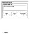
- FIG. 6is a schematic diagram of a computer program product in accordance with an example embodiment.
- This disclosurerelates to apparatuses and methods for transportation to destinations by a self-driving vehicle configured to follow a baseline trajectory.
- Changes to the baseline trajectoryare received by a computer system associated with the vehicle.
- the computer systemmay then create a function representing the current trajectory of the vehicle, as well as one or more functions defining any desired trajectory criteria, and generate an optimization problem from the functions, which, when solved, provide a new, transitional trajectory for the vehicle to follow that moves efficiently and smoothly toward the changed baseline trajectory.
- Some methods disclosed hereinmay be carried out in part or in full by a vehicle configured to operate in an autonomous mode with or without external interaction (e.g., such as from a user of the vehicle).
- Other methods disclosed hereinmay be carried out in part or in full by a server.
- a servermay receive data from the vehicle, from a user input, and/or from one or more sensors observing one or more aspects of an environment of a vehicle.
- the sensor datacould be transmitted to the server using a wireless communication system.
- Other interactions between a vehicle operating in an autonomous mode and a serverare possible within the context of the disclosure.
- Non-transitory computer readable mediawith stored instructions.
- the instructionscould be executable by a computing device to cause the computing device to perform functions similar to those described in the methods described below.
- FIG. 1is a functional block diagram illustrating a vehicle 100 in accordance with an example embodiment.
- the vehicle 100may take the form of a car, truck, motorcycle, bus, boat, airplane, helicopter, lawn mower, earth mover, snowmobile, aircraft, recreational vehicle, amusement park vehicle, farm equipment, construction equipment, tram, golf cart, train, and trolley, for example. Other vehicles are possible as well.
- the vehicle 100may be configured to operate fully or partially in an autonomous mode.
- the vehicle 100may control itself while in the autonomous mode, and may be operable to determine a current state of the vehicle and its environment, determine a predicted behavior of at least one other vehicle in the environment, determine a confidence level that may correspond to a likelihood of the at least one other vehicle to perform the predicted behavior, and control the vehicle 100 based on the determined information. While in autonomous mode, the vehicle 100 may be configured to operate without human interaction.
- the vehicle 100may include various subsystems such as a propulsion system 102 , a sensor system 104 , a control system 106 , one or more peripherals 108 , as well as a power supply 110 , a computer system 112 , and a user interface 116 .
- the vehicle 100may include more or fewer subsystems and each subsystem could include multiple elements. Further, each of the subsystems and elements of vehicle 100 could be interconnected. Thus, one or more of the described functions of the vehicle 100 may be divided up into additional functional or physical components or combined into fewer functional or physical components. In some further examples, additional functional and physical components may be added to the examples illustrated by FIG. 1 .
- the propulsion system 102may include components operable to provide powered motion for the vehicle 100 .
- the propulsion system 102may include an engine 118 , an energy source 119 , a transmission 120 , and wheels 121 .
- the engine 118may be any combination of an internal combustion engine, an electric motor, steam engine, Stirling engine, or other types of engines or motors.
- the engine 118may be configured to convert energy source 119 into mechanical energy.
- the propulsion system 102may include multiple types of engines or motors. For instance, a gas-electric hybrid car could include a gasoline engine and an electric motor. Other examples are possible.
- the energy source 119may represent a source of energy that may, in full or in part, power the engine 118 . That is, the engine 118 could be configured to convert the energy source 119 into mechanical energy. Examples of energy sources 119 include gasoline, diesel, other petroleum-based fuels, propane, other compressed gas-based fuels, ethanol, solar panels, batteries, and other sources of electrical power. The energy source(s) 119 could additionally or alternatively include any combination of fuel tanks, batteries, capacitors, or flywheels. The energy source 119 may also provide energy for other systems of the vehicle 100 .
- the transmission 120may include elements that are operable to transmit mechanical power from the engine 118 to the wheels 121 .
- the transmission 120could include a gearbox, a clutch, a differential, and drive shafts.
- the transmission 120may include other elements.
- the drive shaftsmay include one or more axles that could be coupled to the one or more wheels 121 .
- the wheels 121 of the vehicle 100may be tires.
- the wheels 121 of the vehicle 100may be configured in various formats, including a unicycle, bicycle, tricycle, or a four-wheel format, such as on a car or a truck, for example. Other wheel geometries are possible, such as those including six or more wheels. Any combination of the wheels 121 of vehicle 100 may be operable to rotate differentially with respect to other wheels 121 .
- the wheels 121may represent at least one wheel that is fixedly attached to the transmission 120 and at least one tire coupled to a rim of the wheel that could make contact with the driving surface.
- the wheels 121may include a combination of metal and rubber, or another combination of materials.
- the sensor system 104may include a number of sensors configured to sense information about an environment of the vehicle 100 .
- the sensor system 104may include a Global Positioning System (GPS) 122 , an inertial measurement unit (IMU) 124 , a RADAR unit 126 , a laser rangefinder/LIDAR unit 128 , and a camera 130 .
- GPSGlobal Positioning System
- IMUinertial measurement unit
- RADAR unit 126e.g., a laser rangefinder/LIDAR unit 128
- the sensor system 104may also include sensors configured to monitor internal systems of the vehicle 100 (e.g., an O 2 monitor, a fuel gauge, an engine oil temperature). Other sensors are possible as well.
- One or more of the sensors included in the sensor system 104may be configured to be actuated separately or collectively in order to modify a position, an orientation, or both, of the one or more sensors.
- the GPS 122may be any sensor configured to estimate a geographic location of the vehicle 100 .
- the GPS 122may include a transceiver operable to provide information regarding the position of the vehicle 100 with respect to Earth.
- the IMU 124may include any combination of sensors (e.g., accelerometers and gyroscopes) configured to sense position and orientation changes of the vehicle 100 based on inertial acceleration.
- sensorse.g., accelerometers and gyroscopes
- the RADAR unit 126may represent a system that utilizes radio signals to sense objects within the local environment of the vehicle 100 .
- the RADAR unit 126may additionally be configured to sense the speed and the heading of the objects.
- the laser rangefinder or LIDAR unit 128may be any sensor configured to sense objects in the environment in which the vehicle 100 is located using lasers.
- the laser rangefinder/LIDAR unit 128may include one or more laser sources, a laser scanner, and one or more detectors, among other system components.
- the laser rangefinder/LIDAR unit 128could be configured to operate in a coherent (e.g., using heterodyne detection) or an incoherent detection mode.
- the camera 130may include one or more devices configured to capture a plurality of images of the environment of the vehicle 100 .
- the camera 130may be a still camera or a video camera.
- the control system 106may be configured to control operation of the vehicle 100 and its components. Accordingly, the control system 106 may include various elements such as a steering unit 132 , a throttle 134 , a brake unit 136 , a sensor fusion algorithm 138 , a computer vision system 140 , a navigation/pathing system 142 , and an obstacle avoidance system 144 .
- the steering unit 132may represent any combination of mechanisms that may be operable to adjust the heading of vehicle 100 .
- the throttle 134may be configured to control, for instance, the operating speed of the engine 118 and, in turn, control the speed of the vehicle 100 .
- the brake unit 136could include any combination of mechanisms configured to decelerate the vehicle 100 .
- the brake unit 136could use friction to slow the wheels 121 .
- the brake unit 136may convert the kinetic energy of the wheels 121 to electric current.
- the brake unit 136may take other forms as well.
- the sensor fusion algorithm 138may be an algorithm (or a computer program product storing an algorithm) configured to accept data from the sensor system 104 as an input.
- the datamay include, for example, data representing information sensed at the sensors of the sensor system 104 .
- the sensor fusion algorithm 138may include, for instance, a Kalman filter, a Bayesian network, or other algorithm.
- the sensor fusion algorithm 138may further provide various assessments based on data from the sensor system 104 .
- the assessmentsmay include evaluations of individual objects or features in the environment of the vehicle 100 , evaluation of a particular situation, and evaluate possible impacts based on the particular situation. Other assessments are possible.
- the computer vision system 140may be any system operable to process and analyze images captured by the camera 130 in order to identify objects or features in the environment of the vehicle 100 that could include traffic signals, road way boundaries, and obstacles.
- the computer vision system 140could use an object recognition algorithm, a Structure From Motion (SFM) algorithm, video tracking, and other computer vision techniques.
- SFMStructure From Motion
- the computer vision system 140could be additionally configured to map an environment, track objects, estimate the speed of objects, etc.
- the navigation and pathing system 142may be any system configured to determine a driving path or route for the vehicle 100 .
- the navigation and pathing system 142may additionally be configured to update the driving path dynamically while the vehicle 100 is in operation.
- the navigation and pathing system 142may be configured to incorporate data from the sensor fusion algorithm 138 , the GPS 122 , and one or more predetermined maps so as to determine the driving path for the vehicle 100 .
- the obstacle avoidance system 144may represent a control system configured to identify, evaluate, and avoid or otherwise negotiate potential obstacles in the environment of the vehicle 100 .
- the control system 106may additionally or alternatively include components other than those shown and described.
- Peripherals 108may be configured to allow interaction between the vehicle 100 and external sensors, other vehicles, other computer systems, and/or a user.
- the peripherals 108may include a wireless communication system 146 , a touchscreen 148 , a microphone 150 , and a speaker 152 .
- the peripherals 108may provide, for instance, means for a user of the vehicle 100 to interact with the user interface 116 .
- the touchscreen 148may provide information to a user of the vehicle 100 .
- the user interface 116could also be operable to accept input from the user via the touchscreen 148 .
- the touchscreen 148may be configured to sense at least one of a position and a movement of a user's finger via capacitive sensing, resistance sensing, or a surface acoustic wave process, among other possibilities.
- the touchscreen 148may be capable of sensing finger movement in a direction parallel or planar to the touchscreen surface, in a direction normal to the touchscreen surface, or both, and may also be capable of sensing a level of pressure applied to the touchscreen surface.
- the touchscreen 148may be formed of one or more translucent or transparent insulating layers and one or more translucent or transparent conducting layers. The touchscreen 148 may take other forms as well.
- the peripherals 108may provide means for the vehicle 100 to communicate with devices within its environment.
- the microphone 150may be configured to receive audio (e.g., a voice command or other audio input) from a user of the vehicle 100 .
- the speakers 152may be configured to output audio to a user of the vehicle 100 .
- the wireless communication system 146may be configured to wirelessly communicate with one or more devices directly or via a communication network.
- the wireless communication system 146could use 3G cellular communication, such as CDMA, EVDO, GSM/GPRS, or 4G cellular communication, such as WiMAX or LTE.
- the wireless communication system 146may communicate with a wireless local area network (WLAN), for example, using WIFI®.
- WLANwireless local area network
- the wireless communication system 146may communicate directly with a device, for example, using an infrared link, BLUETOOTH®, or ZIGBEE®.
- Other wireless protocols, such as various vehicular communication systems,are possible within the context of the disclosure.
- the wireless communication system 146may include one or more dedicated short range communications (DSRC) devices that may include public or private data communications between vehicles and/or roadside stations.
- DSRCdedicated short range communications
- the power supply 110may provide power to various components of the vehicle 100 and could represent, for example, a rechargeable lithium-ion or lead-acid battery. In some embodiments, one or more banks of such batteries could be configured to provide electrical power. Other power supply materials and configurations are possible. In some embodiments, the power supply 110 and the energy source 119 could be implemented together, as in some all-electric cars.
- the computer system 112may include at least one processor 113 (which could include at least one microprocessor) that executes instructions 115 stored in a non-transitory computer readable medium, such as the data storage 114 .
- the computer system 112may also represent a plurality of computing devices that may serve to control individual components or subsystems of the vehicle 100 in a distributed fashion.
- the data storage 114may contain instructions 115 (e.g., program logic) executable by the processor 113 to execute various functions of the vehicle 100 , including those described above in connection with FIG. 1 .
- the data storage 114may contain additional instructions as well, including instructions to transmit data to, receive data from, interact with, or control one or more of the propulsion system 102 , the sensor system 104 , the control system 106 , and the peripherals 108 .
- the data storage 114may store data such as roadway maps, path information, among other information. Such information may be used by the vehicle 100 and the computer system 112 at during the operation of the vehicle 100 in the autonomous, semi-autonomous, and/or manual modes.
- the vehicle 100may include a user interface 116 for providing information to or receiving input from a user of the vehicle 100 .
- the user interface 116may control or enable control of content and the layout of interactive images that may be displayed on the touchscreen 148 . Further, the user interface 116 may include one or more input/output devices within the set of peripherals 108 , such as the wireless communication system 146 , the touchscreen 148 , the microphone 150 , and the speaker 152 .
- the computer system 112may control the function of the vehicle 100 based on inputs received from various subsystems (e.g., propulsion system 102 , sensor system 104 , and control system 106 ), as well as from the user interface 116 .
- the computer system 112may utilize input from the control system 106 in order to control the steering unit 132 to avoid an obstacle detected by the sensor system 104 and the obstacle avoidance system 144 .
- the computer system 112could be operable to provide control over many aspects of the vehicle 100 and its subsystems.
- FIG. 1shows various components of vehicle 100 , i.e., wireless communication system 146 , computer system 112 , data storage 114 , and user interface 116 , as being integrated into the vehicle 100
- one or more of these componentscould be mounted or associated separately from the vehicle 100 .
- data storage 114could, in part or in full, exist separate from the vehicle 100 .
- the vehicle 100could be provided in the form of device elements that may be located separately or together.
- the device elements that make up vehicle 100could be communicatively coupled together in a wired or wireless fashion.
- FIG. 2is a vehicle 200 in accordance with an example embodiment.
- FIG. 2shows a vehicle 200 that could be similar or identical to the vehicle 100 described in reference to FIG. 1 .
- the vehicle 200is illustrated in FIG. 2 as a car, other embodiments are possible.
- the vehicle 200could represent a truck, a van, a semi-trailer truck, a motorcycle, a golf cart, an off-road vehicle, or a farm vehicle, among other examples.
- the vehicle 200includes a sensor unit 202 , a wireless communication system 204 , a LIDAR unit 206 , a laser rangefinder unit 208 , and a camera 210 .
- the vehicle 200may include some or all of the elements described with reference to FIG. 1 .
- the sensor unit 202may include one or more different sensors configured to capture information about an environment surrounding the vehicle 200 .
- sensor unit 202could include any combination of cameras, RADARs, LIDARs, range finders, and acoustic sensors. Other types of sensors are possible.
- the sensor unit 202could include one or more movable mounts that could be operable to adjust the orientation of one or more sensors in the sensor unit 202 .
- the movable mountcould include a rotating platform that could scan sensors so as to obtain information from each direction around the vehicle 200 .
- the movable mount of the sensor unit 202could be moveable in a scanning fashion within a particular range of angles and azimuths.
- the sensor unit 202could be mounted atop the roof of a car, for instance, however other mounting locations are possible. Additionally, the sensors of sensor unit 202 could be distributed in different locations and need not be collocated in a single location. Some possible sensor types and mounting locations include LIDAR unit 206 and laser rangefinder unit 208 . Furthermore, each sensor of sensor unit 202 could be configured to be moved or scanned independently of other sensors of sensor unit 202 .
- the wireless communication system 204may be located on a roof of the vehicle 200 , as depicted in FIG. 2 . Alternatively, the wireless communication system 204 may be located, fully or in part, elsewhere.
- the wireless communication system 204may include wireless transmitters and receivers that could be configured to communicate with devices external or internal to the vehicle 200 .
- the wireless communication system 204may include transceivers configured to communicate with other vehicles or computing devices, for instance, in a vehicular communication system or a roadway station. Examples of such vehicular communication systems include dedicated short range communications (DSRC), radio frequency identification (RFID), and other proposed communication standards directed towards intelligent transport systems.
- DSRCdedicated short range communications
- RFIDradio frequency identification
- the camera 210may be any camera (e.g., a still camera, a video camera, etc.) configured to capture a plurality of images of the environment of the vehicle 200 .
- the camera 210may be configured to detect visible light, or may be configured to detect light from other portions of the spectrum, such as infrared or ultraviolet light. Other types of cameras are possible as well.
- the camera 210may be a two-dimensional detector, or may have a three-dimensional spatial range.
- the camera 210may be, for example, a range detector configured to generate a two-dimensional image indicating a distance from the camera 210 to a number of points in the environment.
- the camera 210may use one or more range detecting techniques.
- the camera 210may use a structured light technique in which the vehicle 200 illuminates an object in the environment with a predetermined light pattern, such as a grid or checkerboard pattern, and uses the camera 210 to detect a reflection of the predetermined light pattern off the object. Based on distortions in the reflected light pattern, the vehicle 200 may determine the distance to the points on the object.
- the predetermined light patternmay comprise infrared light, or light of another wavelength.
- the camera 210may use a laser scanning technique in which the vehicle 200 emits a laser and scans across a number of points on an object in the environment. While scanning the object, the vehicle 200 uses the camera 210 to detect a reflection of the laser off the object for each point. Based on a length of time it takes the laser to reflect off the object at each point, the vehicle 200 may determine the distance to the points on the object.
- the camera 210may use a time-of-flight technique in which the vehicle 200 emits a light pulse and uses the camera 210 to detect a reflection of the light pulse off an object at a number of points on the object.
- the camera 210may include a number of pixels, and each pixel may detect the reflection of the light pulse from a point on the object. Based on a length of time it takes the light pulse to reflect off the object at each point, the vehicle 200 may determine the distance to the points on the object.
- the light pulsemay be a laser pulse.
- Other range detecting techniquesare possible as well, including stereo triangulation, sheet-of-light triangulation, interferometry, and coded aperture techniques, among others.
- the camera 210may take other forms as well.
- the camera 210may be mounted inside a front windshield of the vehicle 200 . Specifically, as illustrated, the camera 210 could capture images from a forward-looking view with respect to the vehicle 200 . Other mounting locations and viewing angles of camera 210 are possible, either inside or outside the vehicle 200 .
- the camera 210may have associated optics that could be operable to provide an adjustable field of view. Further, the camera 210 may be mounted to the vehicle 200 with a movable mount that could be operable to vary a pointing angle of the camera 210 .
- the components of the vehicle 100 and the vehicle 200may be configured to work in an interconnected fashion with other components within or outside their respective systems.
- a vehicleIn the manual and semi-autonomous modes, a vehicle is driven entirely and partially, respectively, by a user. In contrast, in a fully autonomous mode, a vehicle, such as the vehicle 100 or the vehicle 200 with reference to FIGS. 1 and 2 , for example, is controlled by a computer system to be driven with little or no user interaction.
- FIG. 3Ais a schematic illustrating an autonomous vehicle operating scenario 300 in accordance with an example embodiment.
- a vehicle 310is driving on a road 320 in the autonomous mode.
- the road 320 in FIG. 3Acomprises two lanes, a left lane 322 and a right lane 324 .
- the portion of the road 320is straight and there are no obstacles or objects present on the road 322 .
- the vehicle 310may be configured to follow a trajectory 330 in the autonomous mode.
- the trajectory 330is shown as being positioned in the center of the left lane 322 of the road 320 .
- the trajectory 330indicates an estimate of the route the vehicle 310 should follow.
- the trajectory 330may be a periodic input into a computer system of the vehicle 330 , and may change based on a number of factors.
- Sensorssuch as sensor system 104 of FIGS. 1 and 2 , may be configured to sense information about an environment of the vehicle 310 .
- the information received by the computer system from the sensorsmay be used to determine an estimate the center of a road lane or an object detected about the environment of the vehicle 310 , for example. This information, in turn, may be used to update the trajectory 330 .
- a path 340is the route the vehicle 310 is currently driving. Although the vehicle 310 is configured to follow the trajectory 330 , the path 340 may not match the trajectory 330 .
- the path 340may not match the trajectory 330 due to a number of reasons. For example, the estimate of the trajectory 330 may be noisy or may be frequently changing, making it difficult for the vehicle 310 to follow the trajectory 330 smoothly and precisely.
- FIG. 3Bis a schematic further illustrating the autonomous vehicle operating scenario 300 of FIG. 3A .
- the road 320transitions from a straight portion 326 to a curved portion 328 .
- another objectmay be detected on the road 322 : a vehicle 360 in the right lane 324 .
- the computer system of the vehicle 310may receive information or data indicating the curved portion 328 of the road 320 and the vehicle 360 , and may update the trajectory 330 accordingly. More specifically, in one example, the computer system of the vehicle 310 may receive information indicating a change in the estimate of the center of the left road lane 322 , and may responsively update the trajectory 330 to follow the changed estimate.
- the trajectory 330curves over the curved portion 328 of the road 320 so as to remain substantially in the center of the left lane 324 and to avoid hitting the vehicle 360 .
- the vehicle 310may update its path 340 so as to continue following the trajectory 330 . If the vehicle 310 moves too quickly from the path 340 to match the trajectory 330 , however, a passenger within the vehicle 310 may perceive an unpleasant jerk, jolt, or yank in a particular direction due to the rapid vehicle movement. However, if the vehicle 310 moves to follow the updated trajectory 330 too slowly, the vehicle 310 may be placed in danger of hitting another vehicle or veering off of the road 320 . For example, in FIG. 3B , if the vehicle 310 does not change course to follow the trajectory 330 quickly enough at the curved portion 328 , the vehicle 310 may pass into the right lane 324 , which may lead to a collision with the vehicle 360 .
- a new, transitional trajectory 350 for the vehicle 310may be generated using an optimization method.
- a non-linear optimization problemmay be created; to do so, the path 340 may first be represented within the computer system of the vehicle 310 as a curve in two-dimensional (2D) space.
- the path 340may be represented as a piecewise polynomial or as a clothoid spline.
- the curve representing the path 340may be defined by a number of vertices, and for each vertex, a function may be defined that depends on the distance of that vertex to the trajectory 330 .
- Other functionsmay additionally be generated by the computer system of the vehicle 310 for the vertex that encode other constraints. For example, constraints that prevent too much deviation from the center of the lane may be provided. In other examples, constraints that avoid detected objects on the road 320 may be encoded in a function. The generated functions result in a non-linear optimization problem that is then solved by the computer system of the vehicle 310 for the best set of the vertices, which will define a transitional trajectory 350 for the vehicle 310 .
- the transitional trajectory 350may be set to match the path 340 of the vehicle 310 up to a pre-determined distance d ahead of the vehicle 310 , and then after the point d, the transitional trajectory 350 may become biased toward the trajectory 330 , in accordance with the solution to the non-linear optimization problem.
- the transitional trajectory 350may remain aligned with the path 340 up until the point d for the purpose of avoiding discontinuities in the input to the steering controller of the vehicle 310 .
- the transitional trajectory 350becomes increasingly biased toward the trajectory 330 , the transitional trajectory 350 may or may not achieve eventual alignment with the trajectory 330 . Whether the transitional trajectory 350 achieves alignment with the trajectory 330 may depend on how far the transitional trajectory 350 is from the trajectory 330 at the point d.
- FIG. 4is a schematic 400 illustrating the generation of a new trajectory for an autonomous vehicle in accordance with an example embodiment.
- the example illustrated in FIG. 4may be used to generate a trajectory such as the transitional trajectory 350 in the operating scenario described with reference to FIGS. 3A-B , for example.
- a first trajectory 410may be represented as a piecewise linear parametric curve including vertices (a_ 1 , . . . a_n), and may represent a trajectory such as the path 340 as described with reference to FIGS. 3A-B .
- the first trajectory 410may represent the route a vehicle is currently driving.
- the first trajectory 410is represented as piecewise linear with three vertices (a_ 1 ), (a_ 2 ), and (a_ 3 ) in 2D space.
- any number of verticesmay comprise a first trajectory.
- Each vertexmay be defined by an origin 412 specific to the vertex and on the first trajectory 410 .
- a second trajectory 420is also shown.
- the second trajectory 420may represent the trajectory 330 described with reference to FIGS. 3A-B .
- the first trajectory 410may be set to follow the second trajectory 420 , as described with reference to FIG. 3A .
- a situationmay occur that causes the second trajectory 420 to change its previously-set course, requiring the first trajectory 410 to change its course as well if it is desired that the first trajectory 410 continue to follow the second trajectory 420 .
- This example scenariowas described with reference to FIG. 3B .
- a functionmay be defined that depends on a distance of a vertex on the first trajectory 410 , such as vertex (a_ 2 ), to the second trajectory 420 .
- the functionmay be a cost function. For example, for vertex (a_ 2 ), a closest point (b_ 2 ) may be located on the trajectory 420 and then a line 414 may be drawn passing through the origin 412 of (a_ 2 ) and through the closest point (b_ 2 ). The function may then be defined for the vertex (a_ 2 ) as a function of its position along the line 414 .
- functiontakes the form of k*(a_ 2 -b_ 2 ) ⁇ 2, so that the function assigns a cost to vertex (a_ 2 ) based on its distance to point (b_ 2 ).
- a functionsuch as the above-described function may be used as a criterion for moving the vehicle on the first trajectory 410 to or near the second trajectory 420 .
- Other functionsmay be constructed on the position of the vertex (a_ 2 ).
- the other functionsmay also be cost functions.
- the values associated with the costmay be positive values, in which case the cost function may seek to minimize the “cost.”
- the values associated with the costmay be negative values, in which case the cost function may seek to maximize the negative “cost,” or may refer to the values as benefits instead of costs and may seek to maximize the benefit.
- An example of another possible constraintincludes a constraint not to deviate too far from the center of a lane, which may be represented using the function
- Another example of a possible constraintis to take into account other objects (for example, other vehicles) on or near the road to bias the new trajectory away from those objects.
- Still another example of a constraintis to construct a function that penalizes a non-smooth trajectory.
- a sum of squares of curvature at each vertex or a rate of change of curvature of the first trajectory 410may be used.
- Still further examples of other cost functionsmay be used.
- Another example cost functionmay include repulsive potentials that push the new trajectory away from other obstacles on the road (e.g., guardrails or vehicles).
- Such an example cost functionmay depend on a variety of factors such as whether the obstacle is static or movable, the obstacle's proximity, size, the relative longitudinal speed between the vehicle and the obstacle (for example, so as to leave a bigger gap when passing or being passed at high relative speed), and the lateral speed of the obstacle. Still other factors for this cost function may be envisioned.
- a non-linear optimization problemmay be solved for the best set of (a — 1, . . . a_n) that defines the new, transitional trajectory.
- the non-linear optimization problemmay be solved efficiently in real-time.
- non-linear optimization problemsare complex to compute; however, the non-linear optimization problem described above provides for solutions to be reached in a more efficient manner. This is in part due to the parametric representation of the first trajectory 410 .
- the curvature of the first trajectory 410 around each vertex “i”may be estimated based on vertices “i ⁇ 1,” “i,” and “i+1,” in contrast to defining a curve parametrically in a manner in which each parameter affects the entire first trajectory 410 .
- the non-linear optimization problemmay rely on an iterative computation of the function at different points in the search space and an estimate of the gradient, or derivative, of the function at those points.
- the optimization methodmay analytically compute the gradient as a function of the current state. This method lends itself to an analytically computable gradient, which is computationally efficient.
- Some example classes of algorithms that may be usedare gradient descent and conjugate gradient optimization methods. Other algorithms may be envisioned as well.
- FIG. 5is a flowchart of a process for controlling an autonomous vehicle in accordance with an example embodiment.
- Method 500 shown in FIG. 5presents an embodiment of a method that, for example, could be used with the vehicles 100 , 200 , and 310 described with reference to FIGS. 1-3B , respectively.
- Method 500may include one or more operations, functions, or actions as illustrated by one or more of blocks 502 - 516 . Although the blocks are illustrated in a sequential order, these blocks may also be performed in parallel, and/or in a different order than those described herein. Also, the various blocks may be combined into fewer blocks, divided into additional blocks, and/or removed based upon the desired implementation.
- the methodincludes controlling, using a computer system, a vehicle in an autonomous mode to follow a first trajectory.
- the computer systemis configured to control a vehicle, such as the vehicles 100 , 200 , and 310 described with reference to FIGS. 1-3B , respectively, in an autonomous mode.
- the first trajectorymay be a portion of the road on which the vehicle is currently driving.
- the first trajectorymay be the path 330 or the first trajectory 410 described with reference to FIGS. 3A-4 , respectively, in one example.
- the methodincludes receiving data indicating a second trajectory.
- the second trajectorymay be a periodic input into the computer system and may indicate the latest estimate of the route the vehicle should follow.
- One or more sensorssuch as the sensor system 104 described with reference to FIG. 1 , may be configured to sense information about the road the vehicle is driving on, as well as the environment around the vehicle. The information gleaned from the sensors may be transmitted and used by a computer system to update the second trajectory. Other information, such as a map comprising roads for vehicle travel and/or other spatial references may be stored in memory and used to update the second trajectory as well.
- an external servermay receive sensor data and/or map information, and generate the second trajectory which is then transmitted to the computer system of the vehicle.
- the methodincludes defining a plurality of vertices based on the first trajectory.
- a parametric curvemay be generated as a piecewise linear curve with a number of vertices in 2D space and may be based on the first trajectory, as described with reference to FIGS. 3A-4 .
- the methodincludes defining a first set of cost functions for the plurality of vertices, wherein each cost function in the first set assigns to a respective vertex in the plurality of vertices a respective cost based on a distance from the respective vertex to the second trajectory.
- a cost functionmay be defined that depends on a distance of a vertex on the first trajectory to the second trajectory.
- the methodincludes defining a second set of cost functions for the plurality of vertices, wherein each cost function in the second set assigns to a respective vertex in the plurality of vertices a respective cost based on at least one other criterion.
- the one other criterionmay encode a constraint on the vehicle movement. Possible constraints may include not deviating too far from the center of a lane, taking into account other objects on or near the road so as to bias the new trajectory away from those objects, and penalizing any movement that results in a non-smooth trajectory. Other example constraints may be envisioned. Functions encoding constraints may be generated to help ensure the vehicle moves smoothly as perceived by a vehicle passenger and/or carefully toward the second trajectory. Sensor data may be used to generate the constraints for the second function.
- the methodincludes optimizing the vertices in the plurality of vertices based on at least the costs assigned by the first set of cost functions and the second set of cost functions.
- Optimizing the verticesmay include generating a non-linear optimization problem from the first and the second cost functions.
- the first and the second sets of cost functionsmay be used in an optimization problem to achieve a transition toward the second trajectory that is quick, smooth, and safe for the vehicle passenger.
- the combination of the first and the second functionsseeks to achieve this balance, and better mimic how a human driver would react to a change in a planned trajectory. Additional functions may be added as well to generate the optimization problem.
- the methodincludes determining a transitional trajectory based on the optimized vertices, wherein the transitional trajectory transitions from the first trajectory to the second trajectory.
- the optimization problemmay be solved for the best set of points along the parametric curve representing the first trajectory to determine the transitional trajectory.
- the methodincludes controlling the vehicle in the autonomous mode to follow the transitional trajectory.
- the computer systemuses the data indicating the transitional trajectory to drive the vehicle along the route of the transitional trajectory.
- the vehicle and any on-board computer systemscould control the vehicle in the autonomous mode.
- computer systemssuch as a server network, could be used to control some or all of the functions of the vehicle in the autonomous mode.
- Example methodssuch as the method 500 of FIG. 5 , may be carried out in whole or in part by the vehicle and its subsystems. Accordingly, example methods could be described by way of example herein as being implemented by the vehicle. However, it should be understood that an example method may be implemented in whole or in part by other computing devices. For example, an example method may be implemented in whole or in part by a server system, which receives data from a device such as those associated with the vehicle. Other examples of computing devices or combinations of computing devices that can implement an example method are possible.
- FIG. 6is a schematic diagram of a computer program product in accordance with an example embodiment. More specifically, FIG. 6 is a conceptual partial view of an example computer program product that includes a computer program for executing a computer process on a computer system.
- the example computer program product 600is provided using a signal bearing medium 602 .
- the signal bearing medium 602may include one or more programming instructions 604 that, when executed by one or more processors may provide functionality or portions of the functionality described above with respect to FIGS. 1-5 .
- the signal bearing medium 602may encompass a computer-readable medium 606 , such as, but not limited to, a hard disk drive, a Compact Disc (CD), a Digital Video Disk (DVD), a digital tape, memory, etc.
- the signal bearing medium 602may encompass a computer recordable medium 608 , such as, but not limited to, memory, read/write (R/W) CDs, R/W DVDs, etc.
- the signal bearing medium 602may encompass a communications medium 610 , such as, but not limited to, a digital and/or an analog communication medium (e.g., a fiber optic cable, a waveguide, a wired communications link, a wireless communication link, etc.).
- a communications medium 610such as, but not limited to, a digital and/or an analog communication medium (e.g., a fiber optic cable, a waveguide, a wired communications link, a wireless communication link, etc.).
- the signal bearing medium 602may be conveyed by a wireless form of the communications medium 610 .
- the one or more programming instructions 604may be, for example, computer executable and/or logic implemented instructions.
- a computing devicesuch as the computer system 112 of FIG. 1 may be configured to provide various operations, functions, or actions in response to the programming instructions 604 conveyed to the computer system 112 by one or more of the computer readable medium 606 , the computer recordable medium 608 , and/or the communications medium 610 .
- the non-transitory computer readable mediumcould also be distributed among multiple data storage elements, which could be remotely located from each other.
- the computing device that executes some or all of the stored instructionscould be a vehicle, such as the vehicle 200 illustrated in FIG. 2 .
- the computing device that executes some or all of the stored instructionscould be another computing device, such as a server.
Landscapes
- Engineering & Computer Science (AREA)
- Transportation (AREA)
- Mechanical Engineering (AREA)
- Chemical & Material Sciences (AREA)
- Combustion & Propulsion (AREA)
- Automation & Control Theory (AREA)
- Aviation & Aerospace Engineering (AREA)
- Radar, Positioning & Navigation (AREA)
- Remote Sensing (AREA)
- Physics & Mathematics (AREA)
- General Physics & Mathematics (AREA)
- Traffic Control Systems (AREA)
Abstract
Description
Claims (18)
Priority Applications (1)
| Application Number | Priority Date | Filing Date | Title |
|---|---|---|---|
| US13/616,813US9120485B1 (en) | 2012-09-14 | 2012-09-14 | Methods and systems for smooth trajectory generation for a self-driving vehicle |
Applications Claiming Priority (1)
| Application Number | Priority Date | Filing Date | Title |
|---|---|---|---|
| US13/616,813US9120485B1 (en) | 2012-09-14 | 2012-09-14 | Methods and systems for smooth trajectory generation for a self-driving vehicle |
Publications (1)
| Publication Number | Publication Date |
|---|---|
| US9120485B1true US9120485B1 (en) | 2015-09-01 |
Family
ID=53938753
Family Applications (1)
| Application Number | Title | Priority Date | Filing Date |
|---|---|---|---|
| US13/616,813Active2033-03-31US9120485B1 (en) | 2012-09-14 | 2012-09-14 | Methods and systems for smooth trajectory generation for a self-driving vehicle |
Country Status (1)
| Country | Link |
|---|---|
| US (1) | US9120485B1 (en) |
Cited By (156)
| Publication number | Priority date | Publication date | Assignee | Title |
|---|---|---|---|---|
| US20160101838A1 (en)* | 2014-10-14 | 2016-04-14 | Furuno Electric Co., Ltd. | Navigation route generation device, automatic steering system, and navigation route generation method |
| US9405293B2 (en)* | 2014-05-30 | 2016-08-02 | Nissan North America, Inc | Vehicle trajectory optimization for autonomous vehicles |
| US9429947B1 (en) | 2016-04-14 | 2016-08-30 | Eric John Wengreen | Self-driving vehicle systems and methods |
| US9551992B1 (en)* | 2016-01-08 | 2017-01-24 | Google Inc. | Fall back trajectory systems for autonomous vehicles |
| US9645577B1 (en) | 2016-03-23 | 2017-05-09 | nuTonomy Inc. | Facilitating vehicle driving and self-driving |
| US9740202B2 (en)* | 2016-01-08 | 2017-08-22 | Waymo Llc | Fall back trajectory systems for autonomous vehicles |
| US9761140B2 (en) | 2015-05-15 | 2017-09-12 | Pied Parker, Inc. | Vehicle detection systems and methods of operation thereof |
| US9898005B2 (en) | 2016-06-24 | 2018-02-20 | Toyota Motor Engineering & Manufacturing North America, Inc. | Driving path determination for autonomous vehicles |
| US20180086336A1 (en)* | 2016-09-29 | 2018-03-29 | The Charles Stark Draper Laboratory, Inc. | Autonomous vehicle: modular architecture |
| WO2018063250A1 (en)* | 2016-09-29 | 2018-04-05 | The Charles Stark Draper Laboratory, Inc. | Autonomous vehicle with modular architecture |
| US9952594B1 (en) | 2017-04-07 | 2018-04-24 | TuSimple | System and method for traffic data collection using unmanned aerial vehicles (UAVs) |
| US9953236B1 (en) | 2017-03-10 | 2018-04-24 | TuSimple | System and method for semantic segmentation using dense upsampling convolution (DUC) |
| US9953538B1 (en)* | 2017-01-17 | 2018-04-24 | Lyft, Inc. | Autonomous vehicle notification system |
| US10012984B2 (en)* | 2015-12-14 | 2018-07-03 | Mitsubishi Electric Research Laboratories, Inc. | System and method for controlling autonomous vehicles |
| US10060749B2 (en)* | 2015-02-19 | 2018-08-28 | Here Global B.V. | Method and apparatus for creating a clothoid road geometry |
| US10067509B1 (en) | 2017-03-10 | 2018-09-04 | TuSimple | System and method for occluding contour detection |
| CN108692734A (en)* | 2017-04-07 | 2018-10-23 | 北京图森未来科技有限公司 | A kind of paths planning method and device |
| US10126136B2 (en) | 2016-06-14 | 2018-11-13 | nuTonomy Inc. | Route planning for an autonomous vehicle |
| US10147193B2 (en) | 2017-03-10 | 2018-12-04 | TuSimple | System and method for semantic segmentation using hybrid dilated convolution (HDC) |
| US10223844B1 (en) | 2018-09-18 | 2019-03-05 | Wesley Edward Schwie | Self-driving vehicle systems and methods |
| US10240938B1 (en) | 2018-10-22 | 2019-03-26 | Drivent Technologies Inc. | Self-driving vehicle systems and methods |
| US10244094B2 (en) | 2016-08-18 | 2019-03-26 | nuTonomy Inc. | Hailing a vehicle |
| US10245994B2 (en) | 2016-08-17 | 2019-04-02 | Toyota Motor Engineering & Manufacturing North America, Inc. | Transportation system including autonomous detachable engine modules and passenger module |
| US10255648B2 (en) | 2016-04-14 | 2019-04-09 | Eric John Wengreen | Self-driving vehicle systems and methods |
| US10268192B1 (en) | 2018-01-06 | 2019-04-23 | Drivent Technologies Inc. | Self-driving vehicle systems and methods |
| US10282625B1 (en) | 2018-10-01 | 2019-05-07 | Eric John Wengreen | Self-driving vehicle systems and methods |
| US10289922B1 (en) | 2018-09-18 | 2019-05-14 | Eric John Wengreen | System for managing lost, mislaid, or abandoned property in a self-driving vehicle |
| US10286908B1 (en) | 2018-11-01 | 2019-05-14 | Eric John Wengreen | Self-driving vehicle systems and methods |
| US10299216B1 (en) | 2018-01-06 | 2019-05-21 | Eric John Wengreen | Self-driving vehicle actions in response to a low battery |
| US10303956B2 (en) | 2017-08-23 | 2019-05-28 | TuSimple | System and method for using triplet loss for proposal free instance-wise semantic segmentation for lane detection |
| US10303181B1 (en) | 2018-11-29 | 2019-05-28 | Eric John Wengreen | Self-driving vehicle systems and methods |
| US10303166B2 (en) | 2016-05-23 | 2019-05-28 | nuTonomy Inc. | Supervisory control of vehicles |
| US10303522B2 (en) | 2017-07-01 | 2019-05-28 | TuSimple | System and method for distributed graphics processing unit (GPU) computation |
| US10309796B2 (en)* | 2003-06-19 | 2019-06-04 | Here Global B.V. | Method of representing road lanes |
| US10309792B2 (en) | 2016-06-14 | 2019-06-04 | nuTonomy Inc. | Route planning for an autonomous vehicle |
| US10311312B2 (en) | 2017-08-31 | 2019-06-04 | TuSimple | System and method for vehicle occlusion detection |
| US10308242B2 (en) | 2017-07-01 | 2019-06-04 | TuSimple | System and method for using human driving patterns to detect and correct abnormal driving behaviors of autonomous vehicles |
| US10331129B2 (en) | 2016-10-20 | 2019-06-25 | nuTonomy Inc. | Identifying a stopping place for an autonomous vehicle |
| US10360257B2 (en) | 2017-08-08 | 2019-07-23 | TuSimple | System and method for image annotation |
| US10377342B1 (en) | 2019-02-04 | 2019-08-13 | Drivent Technologies Inc. | Self-driving vehicle systems and methods |
| US10387736B2 (en) | 2017-09-20 | 2019-08-20 | TuSimple | System and method for detecting taillight signals of a vehicle |
| US10410055B2 (en) | 2017-10-05 | 2019-09-10 | TuSimple | System and method for aerial video traffic analysis |
| US10466057B1 (en) | 2018-07-30 | 2019-11-05 | Wesley Edward Schwie | Self-driving vehicle systems and methods |
| US10473470B2 (en) | 2016-10-20 | 2019-11-12 | nuTonomy Inc. | Identifying a stopping place for an autonomous vehicle |
| US10474790B2 (en) | 2017-06-02 | 2019-11-12 | TuSimple | Large scale distributed simulation for realistic multiple-agent interactive environments |
| US10474154B1 (en) | 2018-11-01 | 2019-11-12 | Drivent Llc | Self-driving vehicle systems and methods |
| US10471963B2 (en) | 2017-04-07 | 2019-11-12 | TuSimple | System and method for transitioning between an autonomous and manual driving mode based on detection of a drivers capacity to control a vehicle |
| US10471804B1 (en) | 2018-09-18 | 2019-11-12 | Drivent Llc | Self-driving vehicle systems and methods |
| US10479319B1 (en) | 2019-03-21 | 2019-11-19 | Drivent Llc | Self-driving vehicle systems and methods |
| US10481044B2 (en) | 2017-05-18 | 2019-11-19 | TuSimple | Perception simulation for improved autonomous vehicle control |
| US10493952B1 (en) | 2019-03-21 | 2019-12-03 | Drivent Llc | Self-driving vehicle systems and methods |
| US10493988B2 (en) | 2017-07-01 | 2019-12-03 | TuSimple | System and method for adaptive cruise control for defensive driving |
| DE102018123896A1 (en)* | 2018-06-25 | 2020-01-02 | Trw Automotive Gmbh | Method for operating an at least partially automated vehicle |
| US10528823B2 (en) | 2017-11-27 | 2020-01-07 | TuSimple | System and method for large-scale lane marking detection using multimodal sensor data |
| US10528851B2 (en) | 2017-11-27 | 2020-01-07 | TuSimple | System and method for drivable road surface representation generation using multimodal sensor data |
| US10552979B2 (en) | 2017-09-13 | 2020-02-04 | TuSimple | Output of a neural network method for deep odometry assisted by static scene optical flow |
| US10552691B2 (en) | 2017-04-25 | 2020-02-04 | TuSimple | System and method for vehicle position and velocity estimation based on camera and lidar data |
| US10558864B2 (en) | 2017-05-18 | 2020-02-11 | TuSimple | System and method for image localization based on semantic segmentation |
| US10599150B2 (en) | 2016-09-29 | 2020-03-24 | The Charles Stark Kraper Laboratory, Inc. | Autonomous vehicle: object-level fusion |
| US20200117199A1 (en)* | 2018-10-15 | 2020-04-16 | Zoox, Inc. | Trajectory initialization |
| WO2020092500A1 (en)* | 2018-11-02 | 2020-05-07 | Zoox, Inc. | Trajectory generation |
| US10649458B2 (en) | 2017-09-07 | 2020-05-12 | Tusimple, Inc. | Data-driven prediction-based system and method for trajectory planning of autonomous vehicles |
| US10656644B2 (en) | 2017-09-07 | 2020-05-19 | Tusimple, Inc. | System and method for using human driving patterns to manage speed control for autonomous vehicles |
| US10657390B2 (en) | 2017-11-27 | 2020-05-19 | Tusimple, Inc. | System and method for large-scale lane marking detection using multimodal sensor data |
| US10666730B2 (en) | 2017-10-28 | 2020-05-26 | Tusimple, Inc. | Storage architecture for heterogeneous multimedia data |
| US10671083B2 (en) | 2017-09-13 | 2020-06-02 | Tusimple, Inc. | Neural network architecture system for deep odometry assisted by static scene optical flow |
| US10671873B2 (en) | 2017-03-10 | 2020-06-02 | Tusimple, Inc. | System and method for vehicle wheel detection |
| US10678234B2 (en) | 2017-08-24 | 2020-06-09 | Tusimple, Inc. | System and method for autonomous vehicle control to minimize energy cost |
| US10681513B2 (en) | 2016-10-20 | 2020-06-09 | nuTonomy Inc. | Identifying a stopping place for an autonomous vehicle |
| US10685239B2 (en) | 2018-03-18 | 2020-06-16 | Tusimple, Inc. | System and method for lateral vehicle detection |
| US10685244B2 (en) | 2018-02-27 | 2020-06-16 | Tusimple, Inc. | System and method for online real-time multi-object tracking |
| US10692365B2 (en) | 2017-06-20 | 2020-06-23 | Cavh Llc | Intelligent road infrastructure system (IRIS): systems and methods |
| US10733465B2 (en) | 2017-09-20 | 2020-08-04 | Tusimple, Inc. | System and method for vehicle taillight state recognition |
| US10739775B2 (en) | 2017-10-28 | 2020-08-11 | Tusimple, Inc. | System and method for real world autonomous vehicle trajectory simulation |
| US10737695B2 (en) | 2017-07-01 | 2020-08-11 | Tusimple, Inc. | System and method for adaptive cruise control for low speed following |
| US10744976B1 (en) | 2019-02-04 | 2020-08-18 | Drivent Llc | Self-driving vehicle systems and methods |
| US10752246B2 (en) | 2017-07-01 | 2020-08-25 | Tusimple, Inc. | System and method for adaptive cruise control with proximate vehicle detection |
| US10762673B2 (en) | 2017-08-23 | 2020-09-01 | Tusimple, Inc. | 3D submap reconstruction system and method for centimeter precision localization using camera-based submap and LiDAR-based global map |
| US10762635B2 (en) | 2017-06-14 | 2020-09-01 | Tusimple, Inc. | System and method for actively selecting and labeling images for semantic segmentation |
| RU2731823C1 (en)* | 2017-08-22 | 2020-09-08 | Ниссан Мотор Ко., Лтд. | Method and device for generation of target path for autonomous vehicle |
| US10768626B2 (en) | 2017-09-30 | 2020-09-08 | Tusimple, Inc. | System and method for providing multiple agents for decision making, trajectory planning, and control for autonomous vehicles |
| US10782694B2 (en) | 2017-09-07 | 2020-09-22 | Tusimple, Inc. | Prediction-based system and method for trajectory planning of autonomous vehicles |
| US10783381B2 (en) | 2017-08-31 | 2020-09-22 | Tusimple, Inc. | System and method for vehicle occlusion detection |
| US10782693B2 (en) | 2017-09-07 | 2020-09-22 | Tusimple, Inc. | Prediction-based system and method for trajectory planning of autonomous vehicles |
| US10796402B2 (en)* | 2018-10-19 | 2020-10-06 | Tusimple, Inc. | System and method for fisheye image processing |
| US10794714B2 (en) | 2018-10-01 | 2020-10-06 | Drivent Llc | Self-driving vehicle systems and methods |
| US10812589B2 (en) | 2017-10-28 | 2020-10-20 | Tusimple, Inc. | Storage architecture for heterogeneous multimedia data |
| US10816354B2 (en) | 2017-08-22 | 2020-10-27 | Tusimple, Inc. | Verification module system and method for motion-based lane detection with multiple sensors |
| US10816990B2 (en)* | 2017-12-21 | 2020-10-27 | Baidu Usa Llc | Non-blocking boundary for autonomous vehicle planning |
| US10823575B2 (en)* | 2018-06-27 | 2020-11-03 | Baidu Usa Llc | Reference line smoothing method using piecewise spiral curves with weighted geometry costs |
| US10832569B2 (en) | 2019-04-02 | 2020-11-10 | Drivent Llc | Vehicle detection systems |
| US10829116B2 (en) | 2016-07-01 | 2020-11-10 | nuTonomy Inc. | Affecting functions of a vehicle based on function-related information about its environment |
| US10839234B2 (en) | 2018-09-12 | 2020-11-17 | Tusimple, Inc. | System and method for three-dimensional (3D) object detection |
| US10860018B2 (en) | 2017-11-30 | 2020-12-08 | Tusimple, Inc. | System and method for generating simulated vehicles with configured behaviors for analyzing autonomous vehicle motion planners |
| US10857994B2 (en) | 2016-10-20 | 2020-12-08 | Motional Ad Llc | Identifying a stopping place for an autonomous vehicle |
| US10867512B2 (en) | 2018-02-06 | 2020-12-15 | Cavh Llc | Intelligent road infrastructure system (IRIS): systems and methods |
| US10877476B2 (en) | 2017-11-30 | 2020-12-29 | Tusimple, Inc. | Autonomous vehicle simulation system for analyzing motion planners |
| US10900792B2 (en) | 2018-10-22 | 2021-01-26 | Drivent Llc | Self-driving vehicle systems and methods |
| US10909866B2 (en) | 2018-07-20 | 2021-02-02 | Cybernet Systems Corp. | Autonomous transportation system and methods |
| US10908608B2 (en)* | 2018-01-18 | 2021-02-02 | Baidu Usa Llc | Method and system for stitching planning trajectories from consecutive planning cycles for smooth control execution of autonomous driving vehicles |
| US10942271B2 (en) | 2018-10-30 | 2021-03-09 | Tusimple, Inc. | Determining an angle between a tow vehicle and a trailer |
| US10953880B2 (en) | 2017-09-07 | 2021-03-23 | Tusimple, Inc. | System and method for automated lane change control for autonomous vehicles |
| US10953881B2 (en) | 2017-09-07 | 2021-03-23 | Tusimple, Inc. | System and method for automated lane change control for autonomous vehicles |
| US20210086832A1 (en)* | 2019-09-23 | 2021-03-25 | GM Global Technology Operations LLC | Method and apparatus for lateral movement control |
| US10963462B2 (en) | 2017-04-26 | 2021-03-30 | The Charles Stark Draper Laboratory, Inc. | Enhancing autonomous vehicle perception with off-vehicle collected data |
| US10962979B2 (en) | 2017-09-30 | 2021-03-30 | Tusimple, Inc. | System and method for multitask processing for autonomous vehicle computation and control |
| CN112601869A (en)* | 2020-04-10 | 2021-04-02 | 百度时代网络技术(北京)有限公司 | Secondary planning side-by-side parking method based on path planning |
| US10970564B2 (en) | 2017-09-30 | 2021-04-06 | Tusimple, Inc. | System and method for instance-level lane detection for autonomous vehicle control |
| US11010874B2 (en) | 2018-04-12 | 2021-05-18 | Tusimple, Inc. | Images for perception modules of autonomous vehicles |
| US11009356B2 (en) | 2018-02-14 | 2021-05-18 | Tusimple, Inc. | Lane marking localization and fusion |
| US11009365B2 (en) | 2018-02-14 | 2021-05-18 | Tusimple, Inc. | Lane marking localization |
| US11029693B2 (en) | 2017-08-08 | 2021-06-08 | Tusimple, Inc. | Neural network based vehicle dynamics model |
| US11048260B2 (en) | 2018-11-02 | 2021-06-29 | Zoox, Inc. | Adaptive scaling in trajectory generation |
| US11073838B2 (en) | 2018-01-06 | 2021-07-27 | Drivent Llc | Self-driving vehicle systems and methods |
| US11074542B2 (en)* | 2018-09-27 | 2021-07-27 | Intel Corporation | Automated delivery device and method for delivering a package |
| US11077878B2 (en) | 2018-11-02 | 2021-08-03 | Zoox, Inc. | Dynamic lane biasing |
| US11092446B2 (en) | 2016-06-14 | 2021-08-17 | Motional Ad Llc | Route planning for an autonomous vehicle |
| US11106212B2 (en)* | 2019-03-26 | 2021-08-31 | Baidu Usa Llc | Path planning for complex scenes with self-adjusting path length for autonomous driving vehicles |
| US11104334B2 (en) | 2018-05-31 | 2021-08-31 | Tusimple, Inc. | System and method for proximate vehicle intention prediction for autonomous vehicles |
| US11110918B2 (en) | 2018-11-02 | 2021-09-07 | Zoox, Inc. | Dynamic collision checking |
| US11151393B2 (en) | 2017-08-23 | 2021-10-19 | Tusimple, Inc. | Feature matching and corresponding refinement and 3D submap position refinement system and method for centimeter precision localization using camera-based submap and LiDAR-based global map |
| US11208096B2 (en) | 2018-11-02 | 2021-12-28 | Zoox, Inc. | Cost scaling in trajectory generation |
| US11221622B2 (en) | 2019-03-21 | 2022-01-11 | Drivent Llc | Self-driving vehicle systems and methods |
| US11249184B2 (en) | 2019-05-07 | 2022-02-15 | The Charles Stark Draper Laboratory, Inc. | Autonomous collision avoidance through physical layer tracking |
| US11292480B2 (en) | 2018-09-13 | 2022-04-05 | Tusimple, Inc. | Remote safe driving methods and systems |
| US11305782B2 (en) | 2018-01-11 | 2022-04-19 | Tusimple, Inc. | Monitoring system for autonomous vehicle operation |
| US11312334B2 (en) | 2018-01-09 | 2022-04-26 | Tusimple, Inc. | Real-time remote control of vehicles with high redundancy |
| US11373122B2 (en) | 2018-07-10 | 2022-06-28 | Cavh Llc | Fixed-route service system for CAVH systems |
| US11385642B2 (en) | 2020-02-27 | 2022-07-12 | Zoox, Inc. | Perpendicular cut-in training |
| WO2022152986A1 (en)* | 2021-01-18 | 2022-07-21 | Psa Automobiles Sa | Method and device for monitoring the trajectory of a vehicle traveling on a traffic lane |
| US20220274625A1 (en)* | 2021-02-26 | 2022-09-01 | Zoox, Inc. | Graph neural networks with vectorized object representations in autonomous vehicle systems |
| US11482102B2 (en) | 2017-05-17 | 2022-10-25 | Cavh Llc | Connected automated vehicle highway systems and methods |
| US20220350333A1 (en)* | 2021-04-28 | 2022-11-03 | Shenzhen University | Method and apparatus for continuous path planning, computer device, and storage medium |
| US11495126B2 (en) | 2018-05-09 | 2022-11-08 | Cavh Llc | Systems and methods for driving intelligence allocation between vehicles and highways |
| US11500101B2 (en) | 2018-05-02 | 2022-11-15 | Tusimple, Inc. | Curb detection by analysis of reflection images |
| US11505190B2 (en)* | 2018-05-11 | 2022-11-22 | Volvo Truck Corporation | Method for establishing a path for a vehicle |
| US11587304B2 (en) | 2017-03-10 | 2023-02-21 | Tusimple, Inc. | System and method for occluding contour detection |
| US11644833B2 (en) | 2018-10-01 | 2023-05-09 | Drivent Llc | Self-driving vehicle systems and methods |
| US11654932B2 (en) | 2020-12-28 | 2023-05-23 | Waymo Llc | Architecture for variable motion control envelope |
| US11701931B2 (en) | 2020-06-18 | 2023-07-18 | Tusimple, Inc. | Angle and orientation measurements for vehicles with multiple drivable sections |
| US11735035B2 (en) | 2017-05-17 | 2023-08-22 | Cavh Llc | Autonomous vehicle and cloud control (AVCC) system with roadside unit (RSU) network |
| US11735041B2 (en) | 2018-07-10 | 2023-08-22 | Cavh Llc | Route-specific services for connected automated vehicle highway systems |
| US11810322B2 (en) | 2020-04-09 | 2023-11-07 | Tusimple, Inc. | Camera pose estimation techniques |
| US11807266B2 (en) | 2020-12-04 | 2023-11-07 | Mitsubishi Electric Corporation | Driving system for distribution of planning and control functionality between vehicle device and cloud computing device, vehicle computing device, and cloud computing device |
| US11823460B2 (en) | 2019-06-14 | 2023-11-21 | Tusimple, Inc. | Image fusion for autonomous vehicle operation |
| US11842642B2 (en) | 2018-06-20 | 2023-12-12 | Cavh Llc | Connected automated vehicle highway systems and methods related to heavy vehicles |
| US11841708B2 (en)* | 2020-02-28 | 2023-12-12 | Zoox, Inc. | System and method for adjusting a planned trajectory of an autonomous vehicle |
| US11972690B2 (en) | 2018-12-14 | 2024-04-30 | Beijing Tusen Zhitu Technology Co., Ltd. | Platooning method, apparatus and system of autonomous driving platoon |
| US12057011B2 (en) | 2018-06-28 | 2024-08-06 | Cavh Llc | Cloud-based technology for connected and automated vehicle highway systems |
| US20240273916A1 (en)* | 2021-06-18 | 2024-08-15 | Valeo Vision | Method for detecting an object in a road surface, method for autonomous driving and automotive lighting device |
| US12099121B2 (en) | 2018-12-10 | 2024-09-24 | Beijing Tusen Zhitu Technology Co., Ltd. | Trailer angle measurement method and device, and vehicle |
| US20240326816A1 (en)* | 2023-03-31 | 2024-10-03 | Torc Robotics, Inc. | Lane change path generation using piecewise clothoid segments |
| US12147229B2 (en) | 2019-11-08 | 2024-11-19 | Drivent Llc | Self-driving vehicle systems and methods |
| US12219445B2 (en) | 2018-07-10 | 2025-02-04 | Cavh Llc | Vehicle on-board unit for connected and automated vehicle systems |
| US12270661B2 (en) | 2018-02-14 | 2025-04-08 | Tusimple, Inc. | Lane marking localization and fusion |
| US12384410B2 (en) | 2021-03-05 | 2025-08-12 | The Research Foundation For The State University Of New York | Task-motion planning for safe and efficient urban driving |
Citations (16)
| Publication number | Priority date | Publication date | Assignee | Title |
|---|---|---|---|---|
| US6675074B2 (en) | 2001-08-21 | 2004-01-06 | Robert Bosch Gmbh | Method and system for vehicle trajectory estimation |
| US20080243307A1 (en) | 2007-03-26 | 2008-10-02 | Honda Research Institute Europe Gmbh | Apparatus and Method for Generating and Controlling the Motion of a Robot |
| US20100076640A1 (en) | 2008-09-22 | 2010-03-25 | Komatsu Ltd. | Travel route generating method for unmanned vehicle |
| US20100082194A1 (en) | 2007-07-18 | 2010-04-01 | Hidenori Yabushita | Path planning device and method, cost evaluation device, and moving body |
| US7865277B1 (en) | 2007-05-07 | 2011-01-04 | The United States Of America As Represented By The Secretary Of The Navy | Obstacle avoidance system and method |
| US20110035086A1 (en) | 2008-04-12 | 2011-02-10 | Hyoun Jin Kim | Steering method for vehicle and apparatus thereof |
| US7979158B2 (en) | 2007-07-31 | 2011-07-12 | Rockwell Automation Technologies, Inc. | Blending algorithm for trajectory planning |
| US20110208429A1 (en) | 2010-02-24 | 2011-08-25 | Microsoft Corporation | Route Computation Based on Route-Oriented Vehicle Trajectories |
| US8060239B2 (en) | 2005-12-22 | 2011-11-15 | Siemens Aktiengesellschaft | Method for the determination of a rough trajectory to be followed in a positionally guided manner |
| US20110297070A1 (en) | 2008-11-04 | 2011-12-08 | Riggs Neil P | Propulsion System for an Autonomous Underwater Vehicle |
| US8082102B2 (en)* | 2008-01-14 | 2011-12-20 | The Boeing Company | Computing flight plans for UAVs while routing around obstacles having spatial and temporal dimensions |
| US8126594B2 (en) | 2008-04-29 | 2012-02-28 | Korea Institute Of Science And Technology | Method of generating a walking pattern for a humanoid robot |
| US20120283907A1 (en)* | 2011-05-05 | 2012-11-08 | GM Global Technology Operations LLC | Lane centering fail-safe control using differential braking |
| US8510041B1 (en)* | 2011-05-02 | 2013-08-13 | Google Inc. | Automatic correction of trajectory data |
| US20130253793A1 (en)* | 2011-05-05 | 2013-09-26 | GM Global Technology Operations LLC | Optimal Fusion Of Electric Park Brake And Hydraulic Brake Sub-System Functions To Control Vehicle Direction |
| US20130304300A1 (en)* | 2012-05-11 | 2013-11-14 | Trimble Navigation Ltd. | Path planning autopilot |
- 2012
- 2012-09-14USUS13/616,813patent/US9120485B1/enactiveActive
Patent Citations (16)
| Publication number | Priority date | Publication date | Assignee | Title |
|---|---|---|---|---|
| US6675074B2 (en) | 2001-08-21 | 2004-01-06 | Robert Bosch Gmbh | Method and system for vehicle trajectory estimation |
| US8060239B2 (en) | 2005-12-22 | 2011-11-15 | Siemens Aktiengesellschaft | Method for the determination of a rough trajectory to be followed in a positionally guided manner |
| US20080243307A1 (en) | 2007-03-26 | 2008-10-02 | Honda Research Institute Europe Gmbh | Apparatus and Method for Generating and Controlling the Motion of a Robot |
| US7865277B1 (en) | 2007-05-07 | 2011-01-04 | The United States Of America As Represented By The Secretary Of The Navy | Obstacle avoidance system and method |
| US20100082194A1 (en) | 2007-07-18 | 2010-04-01 | Hidenori Yabushita | Path planning device and method, cost evaluation device, and moving body |
| US7979158B2 (en) | 2007-07-31 | 2011-07-12 | Rockwell Automation Technologies, Inc. | Blending algorithm for trajectory planning |
| US8082102B2 (en)* | 2008-01-14 | 2011-12-20 | The Boeing Company | Computing flight plans for UAVs while routing around obstacles having spatial and temporal dimensions |
| US20110035086A1 (en) | 2008-04-12 | 2011-02-10 | Hyoun Jin Kim | Steering method for vehicle and apparatus thereof |
| US8126594B2 (en) | 2008-04-29 | 2012-02-28 | Korea Institute Of Science And Technology | Method of generating a walking pattern for a humanoid robot |
| US20100076640A1 (en) | 2008-09-22 | 2010-03-25 | Komatsu Ltd. | Travel route generating method for unmanned vehicle |
| US20110297070A1 (en) | 2008-11-04 | 2011-12-08 | Riggs Neil P | Propulsion System for an Autonomous Underwater Vehicle |
| US20110208429A1 (en) | 2010-02-24 | 2011-08-25 | Microsoft Corporation | Route Computation Based on Route-Oriented Vehicle Trajectories |
| US8510041B1 (en)* | 2011-05-02 | 2013-08-13 | Google Inc. | Automatic correction of trajectory data |
| US20120283907A1 (en)* | 2011-05-05 | 2012-11-08 | GM Global Technology Operations LLC | Lane centering fail-safe control using differential braking |
| US20130253793A1 (en)* | 2011-05-05 | 2013-09-26 | GM Global Technology Operations LLC | Optimal Fusion Of Electric Park Brake And Hydraulic Brake Sub-System Functions To Control Vehicle Direction |
| US20130304300A1 (en)* | 2012-05-11 | 2013-11-14 | Trimble Navigation Ltd. | Path planning autopilot |
Non-Patent Citations (2)
| Title |
|---|
| A. Gasparetto et al., A New Method for Smooth Trajectory Planning of Robot Manipulators, Mechanism and Machine Theory 42 (2007) pp. 455-471. |
| Delingette et al., Trajectory Generation with Curvature Constraint Based on Energy Minimization, The Robotics Institute at Carnegie Mellon University Jan. 1, 1991. |
Cited By (274)
| Publication number | Priority date | Publication date | Assignee | Title |
|---|---|---|---|---|
| US10309796B2 (en)* | 2003-06-19 | 2019-06-04 | Here Global B.V. | Method of representing road lanes |
| US9405293B2 (en)* | 2014-05-30 | 2016-08-02 | Nissan North America, Inc | Vehicle trajectory optimization for autonomous vehicles |
| US9616978B2 (en)* | 2014-10-14 | 2017-04-11 | Furuno Electric Company Limited | Navigation route generation device, automatic steering system, and navigation route generation method |
| US20160101838A1 (en)* | 2014-10-14 | 2016-04-14 | Furuno Electric Co., Ltd. | Navigation route generation device, automatic steering system, and navigation route generation method |
| US10060749B2 (en)* | 2015-02-19 | 2018-08-28 | Here Global B.V. | Method and apparatus for creating a clothoid road geometry |
| US9761140B2 (en) | 2015-05-15 | 2017-09-12 | Pied Parker, Inc. | Vehicle detection systems and methods of operation thereof |
| US10438488B2 (en) | 2015-05-15 | 2019-10-08 | Pied Parker Inc. | Vehicle detection systems and methods of operation thereof |
| US11443629B2 (en) | 2015-05-15 | 2022-09-13 | Pied Parker, Inc. | Vehicle detection systems and methods of operation thereof |
| US10012984B2 (en)* | 2015-12-14 | 2018-07-03 | Mitsubishi Electric Research Laboratories, Inc. | System and method for controlling autonomous vehicles |
| US9740202B2 (en)* | 2016-01-08 | 2017-08-22 | Waymo Llc | Fall back trajectory systems for autonomous vehicles |
| US9551992B1 (en)* | 2016-01-08 | 2017-01-24 | Google Inc. | Fall back trajectory systems for autonomous vehicles |
| US9645577B1 (en) | 2016-03-23 | 2017-05-09 | nuTonomy Inc. | Facilitating vehicle driving and self-driving |
| CN109313445B (en)* | 2016-03-23 | 2022-02-18 | 动态Ad有限责任公司 | Vehicle driving and automated driving facilitation |
| CN109313445A (en)* | 2016-03-23 | 2019-02-05 | 优特诺股份有限公司 | Promotion of vehicle driving and autonomous driving |
| US9915949B2 (en) | 2016-04-14 | 2018-03-13 | Wesley Edward Schwie | Self-driving vehicle systems and methods |
| US9646356B1 (en) | 2016-04-14 | 2017-05-09 | Wesley Edward Schwie | Self-driving vehicle systems and methods |
| US10255648B2 (en) | 2016-04-14 | 2019-04-09 | Eric John Wengreen | Self-driving vehicle systems and methods |
| US9429947B1 (en) | 2016-04-14 | 2016-08-30 | Eric John Wengreen | Self-driving vehicle systems and methods |
| US11175656B2 (en) | 2016-05-23 | 2021-11-16 | Motional Ad Llc | Supervisory control of vehicles |
| US10303166B2 (en) | 2016-05-23 | 2019-05-28 | nuTonomy Inc. | Supervisory control of vehicles |
| US10126136B2 (en) | 2016-06-14 | 2018-11-13 | nuTonomy Inc. | Route planning for an autonomous vehicle |
| US11092446B2 (en) | 2016-06-14 | 2021-08-17 | Motional Ad Llc | Route planning for an autonomous vehicle |
| US11022449B2 (en) | 2016-06-14 | 2021-06-01 | Motional Ad Llc | Route planning for an autonomous vehicle |
| US10309792B2 (en) | 2016-06-14 | 2019-06-04 | nuTonomy Inc. | Route planning for an autonomous vehicle |
| US11022450B2 (en) | 2016-06-14 | 2021-06-01 | Motional Ad Llc | Route planning for an autonomous vehicle |
| US9898005B2 (en) | 2016-06-24 | 2018-02-20 | Toyota Motor Engineering & Manufacturing North America, Inc. | Driving path determination for autonomous vehicles |
| US10829116B2 (en) | 2016-07-01 | 2020-11-10 | nuTonomy Inc. | Affecting functions of a vehicle based on function-related information about its environment |
| US10245994B2 (en) | 2016-08-17 | 2019-04-02 | Toyota Motor Engineering & Manufacturing North America, Inc. | Transportation system including autonomous detachable engine modules and passenger module |
| US10632893B2 (en) | 2016-08-17 | 2020-04-28 | Toyota Motor Engineering & Manufacturing North America, Inc. | Transportation system including autonomous detachable engine modules and passenger module |
| US11892844B2 (en) | 2016-08-18 | 2024-02-06 | Motional Ad Llc | Hailing a vehicle |
| US10244094B2 (en) | 2016-08-18 | 2019-03-26 | nuTonomy Inc. | Hailing a vehicle |
| US10884413B2 (en) | 2016-08-18 | 2021-01-05 | Motional Ad Llc | Hailing a vehicle |
| US11449056B2 (en) | 2016-08-18 | 2022-09-20 | Motional Ad Llc | Hailing a vehicle |
| US10409282B2 (en) | 2016-08-18 | 2019-09-10 | nuTonomy Inc. | Hailing a vehicle |
| US10599150B2 (en) | 2016-09-29 | 2020-03-24 | The Charles Stark Kraper Laboratory, Inc. | Autonomous vehicle: object-level fusion |
| WO2018063250A1 (en)* | 2016-09-29 | 2018-04-05 | The Charles Stark Draper Laboratory, Inc. | Autonomous vehicle with modular architecture |
| US20180086336A1 (en)* | 2016-09-29 | 2018-03-29 | The Charles Stark Draper Laboratory, Inc. | Autonomous vehicle: modular architecture |
| US10377375B2 (en)* | 2016-09-29 | 2019-08-13 | The Charles Stark Draper Laboratory, Inc. | Autonomous vehicle: modular architecture |
| US10473470B2 (en) | 2016-10-20 | 2019-11-12 | nuTonomy Inc. | Identifying a stopping place for an autonomous vehicle |
| US10681513B2 (en) | 2016-10-20 | 2020-06-09 | nuTonomy Inc. | Identifying a stopping place for an autonomous vehicle |
| US11711681B2 (en) | 2016-10-20 | 2023-07-25 | Motional Ad Llc | Identifying a stopping place for an autonomous vehicle |
| US10331129B2 (en) | 2016-10-20 | 2019-06-25 | nuTonomy Inc. | Identifying a stopping place for an autonomous vehicle |
| US10857994B2 (en) | 2016-10-20 | 2020-12-08 | Motional Ad Llc | Identifying a stopping place for an autonomous vehicle |
| US10152892B2 (en)* | 2017-01-17 | 2018-12-11 | Lyft, Inc. | Autonomous vehicle notification system |
| US9953538B1 (en)* | 2017-01-17 | 2018-04-24 | Lyft, Inc. | Autonomous vehicle notification system |
| US12277860B2 (en)* | 2017-01-17 | 2025-04-15 | Lyft, Inc. | Autonomous vehicle notification system |
| US10607491B2 (en)* | 2017-01-17 | 2020-03-31 | Lyft Inc. | Autonomous vehicle notification system |
| US20200219397A1 (en)* | 2017-01-17 | 2020-07-09 | Lyft, Inc. | Autonomous vehicle notification system |
| US20230093599A1 (en)* | 2017-01-17 | 2023-03-23 | Lyft, Inc. | Autonomous vehicle notification system |
| US11562651B2 (en)* | 2017-01-17 | 2023-01-24 | Lyft, Inc. | Autonomous vehicle notification system |
| US10671873B2 (en) | 2017-03-10 | 2020-06-02 | Tusimple, Inc. | System and method for vehicle wheel detection |
| US11587304B2 (en) | 2017-03-10 | 2023-02-21 | Tusimple, Inc. | System and method for occluding contour detection |
| US9953236B1 (en) | 2017-03-10 | 2018-04-24 | TuSimple | System and method for semantic segmentation using dense upsampling convolution (DUC) |
| US11501513B2 (en) | 2017-03-10 | 2022-11-15 | Tusimple, Inc. | System and method for vehicle wheel detection |
| US11967140B2 (en) | 2017-03-10 | 2024-04-23 | Tusimple, Inc. | System and method for vehicle wheel detection |
| US10067509B1 (en) | 2017-03-10 | 2018-09-04 | TuSimple | System and method for occluding contour detection |
| US10147193B2 (en) | 2017-03-10 | 2018-12-04 | TuSimple | System and method for semantic segmentation using hybrid dilated convolution (HDC) |
| US11673557B2 (en) | 2017-04-07 | 2023-06-13 | Tusimple, Inc. | System and method for path planning of autonomous vehicles based on gradient |
| CN108692734B (en)* | 2017-04-07 | 2020-07-07 | 北京图森未来科技有限公司 | A path planning method and device |
| US10710592B2 (en) | 2017-04-07 | 2020-07-14 | Tusimple, Inc. | System and method for path planning of autonomous vehicles based on gradient |
| US9952594B1 (en) | 2017-04-07 | 2018-04-24 | TuSimple | System and method for traffic data collection using unmanned aerial vehicles (UAVs) |
| US10471963B2 (en) | 2017-04-07 | 2019-11-12 | TuSimple | System and method for transitioning between an autonomous and manual driving mode based on detection of a drivers capacity to control a vehicle |
| CN108692734A (en)* | 2017-04-07 | 2018-10-23 | 北京图森未来科技有限公司 | A kind of paths planning method and device |
| US11557128B2 (en) | 2017-04-25 | 2023-01-17 | Tusimple, Inc. | System and method for vehicle position and velocity estimation based on camera and LIDAR data |
| US11928868B2 (en) | 2017-04-25 | 2024-03-12 | Tusimple, Inc. | System and method for vehicle position and velocity estimation based on camera and LIDAR data |
| US10552691B2 (en) | 2017-04-25 | 2020-02-04 | TuSimple | System and method for vehicle position and velocity estimation based on camera and lidar data |
| US10963462B2 (en) | 2017-04-26 | 2021-03-30 | The Charles Stark Draper Laboratory, Inc. | Enhancing autonomous vehicle perception with off-vehicle collected data |
| US11935402B2 (en) | 2017-05-17 | 2024-03-19 | Cavh Llc | Autonomous vehicle and center control system |
| US12008893B2 (en) | 2017-05-17 | 2024-06-11 | Cavh Llc | Autonomous vehicle (AV) control system with roadside unit (RSU) network |
| US12333932B2 (en) | 2017-05-17 | 2025-06-17 | Cavh Llc | Roadside edge computing system for autonomous vehicles |
| US11482102B2 (en) | 2017-05-17 | 2022-10-25 | Cavh Llc | Connected automated vehicle highway systems and methods |
| US11990034B2 (en) | 2017-05-17 | 2024-05-21 | Cavh Llc | Autonomous vehicle control system with traffic control center/traffic control unit (TCC/TCU) and RoadSide Unit (RSU) network |
| US11735035B2 (en) | 2017-05-17 | 2023-08-22 | Cavh Llc | Autonomous vehicle and cloud control (AVCC) system with roadside unit (RSU) network |
| US12266262B2 (en) | 2017-05-17 | 2025-04-01 | Cavh Llc | Autonomous vehicle cloud system |
| US12260746B2 (en) | 2017-05-17 | 2025-03-25 | Cavh Llc | Autonomous vehicle intelligent system (AVIS) |
| US12020563B2 (en) | 2017-05-17 | 2024-06-25 | Cavh Llc | Autonomous vehicle and cloud control system |
| US12327471B2 (en) | 2017-05-17 | 2025-06-10 | Cavh Llc | Vehicle AI computing system (VACS) for autonomous driving |
| US11955002B2 (en) | 2017-05-17 | 2024-04-09 | Cavh Llc | Autonomous vehicle control system with roadside unit (RSU) network's global sensing |
| US10867188B2 (en) | 2017-05-18 | 2020-12-15 | Tusimple, Inc. | System and method for image localization based on semantic segmentation |
| US10830669B2 (en) | 2017-05-18 | 2020-11-10 | Tusimple, Inc. | Perception simulation for improved autonomous vehicle control |
| US11885712B2 (en) | 2017-05-18 | 2024-01-30 | Tusimple, Inc. | Perception simulation for improved autonomous vehicle control |
| US12228472B2 (en) | 2017-05-18 | 2025-02-18 | Tusimple, Inc. | Perception simulation for improved autonomous vehicle control |
| US10481044B2 (en) | 2017-05-18 | 2019-11-19 | TuSimple | Perception simulation for improved autonomous vehicle control |
| US10558864B2 (en) | 2017-05-18 | 2020-02-11 | TuSimple | System and method for image localization based on semantic segmentation |
| US10474790B2 (en) | 2017-06-02 | 2019-11-12 | TuSimple | Large scale distributed simulation for realistic multiple-agent interactive environments |
| US10762635B2 (en) | 2017-06-14 | 2020-09-01 | Tusimple, Inc. | System and method for actively selecting and labeling images for semantic segmentation |
| US11881101B2 (en) | 2017-06-20 | 2024-01-23 | Cavh Llc | Intelligent road side unit (RSU) network for automated driving |
| US11430328B2 (en) | 2017-06-20 | 2022-08-30 | Cavh Llc | Intelligent road infrastructure system (IRIS): systems and methods |
| US10692365B2 (en) | 2017-06-20 | 2020-06-23 | Cavh Llc | Intelligent road infrastructure system (IRIS): systems and methods |
| US10737695B2 (en) | 2017-07-01 | 2020-08-11 | Tusimple, Inc. | System and method for adaptive cruise control for low speed following |
| US10303522B2 (en) | 2017-07-01 | 2019-05-28 | TuSimple | System and method for distributed graphics processing unit (GPU) computation |
| US10752246B2 (en) | 2017-07-01 | 2020-08-25 | Tusimple, Inc. | System and method for adaptive cruise control with proximate vehicle detection |
| US10308242B2 (en) | 2017-07-01 | 2019-06-04 | TuSimple | System and method for using human driving patterns to detect and correct abnormal driving behaviors of autonomous vehicles |
| US11753008B2 (en) | 2017-07-01 | 2023-09-12 | Tusimple, Inc. | System and method for adaptive cruise control with proximate vehicle detection |
| US11958473B2 (en) | 2017-07-01 | 2024-04-16 | Tusimple, Inc. | System and method for using human driving patterns to detect and correct abnormal driving behaviors of autonomous vehicles |
| US10493988B2 (en) | 2017-07-01 | 2019-12-03 | TuSimple | System and method for adaptive cruise control for defensive driving |
| US11040710B2 (en) | 2017-07-01 | 2021-06-22 | Tusimple, Inc. | System and method for using human driving patterns to detect and correct abnormal driving behaviors of autonomous vehicles |
| US11550329B2 (en) | 2017-08-08 | 2023-01-10 | Tusimple, Inc. | Neural network based vehicle dynamics model |
| US11029693B2 (en) | 2017-08-08 | 2021-06-08 | Tusimple, Inc. | Neural network based vehicle dynamics model |
| US10360257B2 (en) | 2017-08-08 | 2019-07-23 | TuSimple | System and method for image annotation |
| US12007778B2 (en) | 2017-08-08 | 2024-06-11 | Tusimple, Inc. | Neural network based vehicle dynamics model |
| US11573095B2 (en) | 2017-08-22 | 2023-02-07 | Tusimple, Inc. | Verification module system and method for motion-based lane detection with multiple sensors |
| US11874130B2 (en) | 2017-08-22 | 2024-01-16 | Tusimple, Inc. | Verification module system and method for motion-based lane detection with multiple sensors |
| RU2731823C1 (en)* | 2017-08-22 | 2020-09-08 | Ниссан Мотор Ко., Лтд. | Method and device for generation of target path for autonomous vehicle |
| US10816354B2 (en) | 2017-08-22 | 2020-10-27 | Tusimple, Inc. | Verification module system and method for motion-based lane detection with multiple sensors |
| US12276516B2 (en) | 2017-08-22 | 2025-04-15 | Tusimple, Inc. | Verification module system and method for motion-based lane detection with multiple sensors |
| US10303956B2 (en) | 2017-08-23 | 2019-05-28 | TuSimple | System and method for using triplet loss for proposal free instance-wise semantic segmentation for lane detection |
| US11846510B2 (en) | 2017-08-23 | 2023-12-19 | Tusimple, Inc. | Feature matching and correspondence refinement and 3D submap position refinement system and method for centimeter precision localization using camera-based submap and LiDAR-based global map |
| US10762673B2 (en) | 2017-08-23 | 2020-09-01 | Tusimple, Inc. | 3D submap reconstruction system and method for centimeter precision localization using camera-based submap and LiDAR-based global map |
| US12228409B2 (en) | 2017-08-23 | 2025-02-18 | Tusimple, Inc. | Feature matching and correspondence refinement and 3D submap position refinement system and method for centimeter precision localization using camera-based submap and LiDAR-based global map |
| US11151393B2 (en) | 2017-08-23 | 2021-10-19 | Tusimple, Inc. | Feature matching and corresponding refinement and 3D submap position refinement system and method for centimeter precision localization using camera-based submap and LiDAR-based global map |
| US10678234B2 (en) | 2017-08-24 | 2020-06-09 | Tusimple, Inc. | System and method for autonomous vehicle control to minimize energy cost |
| US11366467B2 (en) | 2017-08-24 | 2022-06-21 | Tusimple, Inc. | System and method for autonomous vehicle control to minimize energy cost |
| US11886183B2 (en) | 2017-08-24 | 2024-01-30 | Tusimple, Inc. | System and method for autonomous vehicle control to minimize energy cost |
| US12253850B2 (en) | 2017-08-24 | 2025-03-18 | Tusimple, Inc. | System and method for autonomous vehicle control to minimize energy cost |
| US11745736B2 (en) | 2017-08-31 | 2023-09-05 | Tusimple, Inc. | System and method for vehicle occlusion detection |
| US10783381B2 (en) | 2017-08-31 | 2020-09-22 | Tusimple, Inc. | System and method for vehicle occlusion detection |
| US10311312B2 (en) | 2017-08-31 | 2019-06-04 | TuSimple | System and method for vehicle occlusion detection |
| US10649458B2 (en) | 2017-09-07 | 2020-05-12 | Tusimple, Inc. | Data-driven prediction-based system and method for trajectory planning of autonomous vehicles |
| US11892846B2 (en) | 2017-09-07 | 2024-02-06 | Tusimple, Inc. | Prediction-based system and method for trajectory planning of autonomous vehicles |
| US10953881B2 (en) | 2017-09-07 | 2021-03-23 | Tusimple, Inc. | System and method for automated lane change control for autonomous vehicles |
| US10656644B2 (en) | 2017-09-07 | 2020-05-19 | Tusimple, Inc. | System and method for using human driving patterns to manage speed control for autonomous vehicles |
| US10782693B2 (en) | 2017-09-07 | 2020-09-22 | Tusimple, Inc. | Prediction-based system and method for trajectory planning of autonomous vehicles |
| US11294375B2 (en) | 2017-09-07 | 2022-04-05 | Tusimple, Inc. | System and method for using human driving patterns to manage speed control for autonomous vehicles |
| US11853071B2 (en) | 2017-09-07 | 2023-12-26 | Tusimple, Inc. | Data-driven prediction-based system and method for trajectory planning of autonomous vehicles |
| US11983008B2 (en) | 2017-09-07 | 2024-05-14 | Tusimple, Inc. | System and method for using human driving patterns to manage speed control for autonomous vehicles |
| US10782694B2 (en) | 2017-09-07 | 2020-09-22 | Tusimple, Inc. | Prediction-based system and method for trajectory planning of autonomous vehicles |
| US10953880B2 (en) | 2017-09-07 | 2021-03-23 | Tusimple, Inc. | System and method for automated lane change control for autonomous vehicles |
| US10552979B2 (en) | 2017-09-13 | 2020-02-04 | TuSimple | Output of a neural network method for deep odometry assisted by static scene optical flow |
| US10671083B2 (en) | 2017-09-13 | 2020-06-02 | Tusimple, Inc. | Neural network architecture system for deep odometry assisted by static scene optical flow |
| US11734563B2 (en) | 2017-09-20 | 2023-08-22 | Tusimple, Inc. | System and method for vehicle taillight state recognition |
| US10387736B2 (en) | 2017-09-20 | 2019-08-20 | TuSimple | System and method for detecting taillight signals of a vehicle |
| US10733465B2 (en) | 2017-09-20 | 2020-08-04 | Tusimple, Inc. | System and method for vehicle taillight state recognition |
| US11328164B2 (en) | 2017-09-20 | 2022-05-10 | Tusimple, Inc. | System and method for vehicle taillight state recognition |
| US12073324B2 (en) | 2017-09-20 | 2024-08-27 | Tusimple, Inc. | System and method for vehicle taillight state recognition |
| US10768626B2 (en) | 2017-09-30 | 2020-09-08 | Tusimple, Inc. | System and method for providing multiple agents for decision making, trajectory planning, and control for autonomous vehicles |
| US12242271B2 (en) | 2017-09-30 | 2025-03-04 | Tusimple, Inc. | System and method for providing multiple agents for decision making, trajectory planning, and control for autonomous vehicles |
| US10970564B2 (en) | 2017-09-30 | 2021-04-06 | Tusimple, Inc. | System and method for instance-level lane detection for autonomous vehicle control |
| US11500387B2 (en) | 2017-09-30 | 2022-11-15 | Tusimple, Inc. | System and method for providing multiple agents for decision making, trajectory planning, and control for autonomous vehicles |
| US10962979B2 (en) | 2017-09-30 | 2021-03-30 | Tusimple, Inc. | System and method for multitask processing for autonomous vehicle computation and control |
| US12242967B2 (en) | 2017-09-30 | 2025-03-04 | Tusimple, Inc. | System and method for instance-level lane detection for autonomous vehicle control |
| US11853883B2 (en) | 2017-09-30 | 2023-12-26 | Tusimple, Inc. | System and method for instance-level lane detection for autonomous vehicle control |
| US10410055B2 (en) | 2017-10-05 | 2019-09-10 | TuSimple | System and method for aerial video traffic analysis |
| US10812589B2 (en) | 2017-10-28 | 2020-10-20 | Tusimple, Inc. | Storage architecture for heterogeneous multimedia data |
| US10666730B2 (en) | 2017-10-28 | 2020-05-26 | Tusimple, Inc. | Storage architecture for heterogeneous multimedia data |
| US11435748B2 (en) | 2017-10-28 | 2022-09-06 | Tusimple, Inc. | System and method for real world autonomous vehicle trajectory simulation |
| US20230004165A1 (en)* | 2017-10-28 | 2023-01-05 | Tusimple, Inc. | System and method for real world autonomous vehicle trajectory simulation |
| US12242274B2 (en) | 2017-10-28 | 2025-03-04 | Tusimple, Inc. | System and method for real world autonomous vehicle trajectory simulation |
| US11853072B2 (en)* | 2017-10-28 | 2023-12-26 | Tusimple, Inc. | System and method for real world autonomous vehicle trajectory simulation |
| US10739775B2 (en) | 2017-10-28 | 2020-08-11 | Tusimple, Inc. | System and method for real world autonomous vehicle trajectory simulation |
| US11580754B2 (en) | 2017-11-27 | 2023-02-14 | Tusimple, Inc. | System and method for large-scale lane marking detection using multimodal sensor data |
| US12148227B2 (en) | 2017-11-27 | 2024-11-19 | Tusimple, Inc. | System and method for large-scale lane marking detection using multimodal sensor data |
| US10657390B2 (en) | 2017-11-27 | 2020-05-19 | Tusimple, Inc. | System and method for large-scale lane marking detection using multimodal sensor data |
| US10528851B2 (en) | 2017-11-27 | 2020-01-07 | TuSimple | System and method for drivable road surface representation generation using multimodal sensor data |
| US10528823B2 (en) | 2017-11-27 | 2020-01-07 | TuSimple | System and method for large-scale lane marking detection using multimodal sensor data |
| US11681292B2 (en) | 2017-11-30 | 2023-06-20 | Tusimple, Inc. | System and method for generating simulated vehicles with configured behaviors for analyzing autonomous vehicle motion planners |
| US10877476B2 (en) | 2017-11-30 | 2020-12-29 | Tusimple, Inc. | Autonomous vehicle simulation system for analyzing motion planners |
| US11782440B2 (en) | 2017-11-30 | 2023-10-10 | Tusimple, Inc. | Autonomous vehicle simulation system for analyzing motion planners |
| US12164296B2 (en) | 2017-11-30 | 2024-12-10 | Tusimple, Inc. | Autonomous vehicle simulation system for analyzing motion planners |
| US12248321B2 (en) | 2017-11-30 | 2025-03-11 | Tusimple, Inc. | System and method for generating simulated vehicles with configured behaviors for analyzing autonomous vehicle motion planners |
| US10860018B2 (en) | 2017-11-30 | 2020-12-08 | Tusimple, Inc. | System and method for generating simulated vehicles with configured behaviors for analyzing autonomous vehicle motion planners |
| US10816990B2 (en)* | 2017-12-21 | 2020-10-27 | Baidu Usa Llc | Non-blocking boundary for autonomous vehicle planning |
| US10268192B1 (en) | 2018-01-06 | 2019-04-23 | Drivent Technologies Inc. | Self-driving vehicle systems and methods |
| US11073838B2 (en) | 2018-01-06 | 2021-07-27 | Drivent Llc | Self-driving vehicle systems and methods |
| US11789460B2 (en) | 2018-01-06 | 2023-10-17 | Drivent Llc | Self-driving vehicle systems and methods |
| US10299216B1 (en) | 2018-01-06 | 2019-05-21 | Eric John Wengreen | Self-driving vehicle actions in response to a low battery |
| US10274950B1 (en) | 2018-01-06 | 2019-04-30 | Drivent Technologies Inc. | Self-driving vehicle systems and methods |
| US12071101B2 (en) | 2018-01-09 | 2024-08-27 | Tusimple, Inc. | Real-time remote control of vehicles with high redundancy |
| US11312334B2 (en) | 2018-01-09 | 2022-04-26 | Tusimple, Inc. | Real-time remote control of vehicles with high redundancy |
| US11305782B2 (en) | 2018-01-11 | 2022-04-19 | Tusimple, Inc. | Monitoring system for autonomous vehicle operation |
| US12122398B2 (en) | 2018-01-11 | 2024-10-22 | Tusimple, Inc. | Monitoring system for autonomous vehicle operation |
| US10908608B2 (en)* | 2018-01-18 | 2021-02-02 | Baidu Usa Llc | Method and system for stitching planning trajectories from consecutive planning cycles for smooth control execution of autonomous driving vehicles |
| US10867512B2 (en) | 2018-02-06 | 2020-12-15 | Cavh Llc | Intelligent road infrastructure system (IRIS): systems and methods |
| US11854391B2 (en) | 2018-02-06 | 2023-12-26 | Cavh Llc | Intelligent road infrastructure system (IRIS): systems and methods |
| US12270661B2 (en) | 2018-02-14 | 2025-04-08 | Tusimple, Inc. | Lane marking localization and fusion |
| US11009356B2 (en) | 2018-02-14 | 2021-05-18 | Tusimple, Inc. | Lane marking localization and fusion |
| US11009365B2 (en) | 2018-02-14 | 2021-05-18 | Tusimple, Inc. | Lane marking localization |
| US12352592B2 (en) | 2018-02-14 | 2025-07-08 | Tusimple, Inc. | Lane marking localization |
| US11740093B2 (en) | 2018-02-14 | 2023-08-29 | Tusimple, Inc. | Lane marking localization and fusion |
| US11852498B2 (en) | 2018-02-14 | 2023-12-26 | Tusimple, Inc. | Lane marking localization |
| US12387348B2 (en) | 2018-02-27 | 2025-08-12 | Tusimple, Inc. | System and method for online real-time multi-object tracking |
| US11295146B2 (en) | 2018-02-27 | 2022-04-05 | Tusimple, Inc. | System and method for online real-time multi-object tracking |
| US10685244B2 (en) | 2018-02-27 | 2020-06-16 | Tusimple, Inc. | System and method for online real-time multi-object tracking |
| US11830205B2 (en) | 2018-02-27 | 2023-11-28 | Tusimple, Inc. | System and method for online real-time multi- object tracking |
| US11074462B2 (en) | 2018-03-18 | 2021-07-27 | Tusimple, Inc. | System and method for lateral vehicle detection |
| US10685239B2 (en) | 2018-03-18 | 2020-06-16 | Tusimple, Inc. | System and method for lateral vehicle detection |
| US12243428B2 (en) | 2018-03-18 | 2025-03-04 | Tusimple, Inc. | System and method for lateral vehicle detection |
| US11610406B2 (en) | 2018-03-18 | 2023-03-21 | Tusimple, Inc. | System and method for lateral vehicle detection |
| US11010874B2 (en) | 2018-04-12 | 2021-05-18 | Tusimple, Inc. | Images for perception modules of autonomous vehicles |
| US12175637B2 (en) | 2018-04-12 | 2024-12-24 | Tusimple, Inc. | Images for perception modules of autonomous vehicles |
| US11694308B2 (en) | 2018-04-12 | 2023-07-04 | Tusimple, Inc. | Images for perception modules of autonomous vehicles |
| US11500101B2 (en) | 2018-05-02 | 2022-11-15 | Tusimple, Inc. | Curb detection by analysis of reflection images |
| US11495126B2 (en) | 2018-05-09 | 2022-11-08 | Cavh Llc | Systems and methods for driving intelligence allocation between vehicles and highways |
| US11505190B2 (en)* | 2018-05-11 | 2022-11-22 | Volvo Truck Corporation | Method for establishing a path for a vehicle |
| US11511746B2 (en) | 2018-05-11 | 2022-11-29 | Volvo Truck Corporation | Method for establishing a path for a vehicle |
| US11948082B2 (en) | 2018-05-31 | 2024-04-02 | Tusimple, Inc. | System and method for proximate vehicle intention prediction for autonomous vehicles |
| US11104334B2 (en) | 2018-05-31 | 2021-08-31 | Tusimple, Inc. | System and method for proximate vehicle intention prediction for autonomous vehicles |
| US11842642B2 (en) | 2018-06-20 | 2023-12-12 | Cavh Llc | Connected automated vehicle highway systems and methods related to heavy vehicles |
| DE102018123896A1 (en)* | 2018-06-25 | 2020-01-02 | Trw Automotive Gmbh | Method for operating an at least partially automated vehicle |
| US10823575B2 (en)* | 2018-06-27 | 2020-11-03 | Baidu Usa Llc | Reference line smoothing method using piecewise spiral curves with weighted geometry costs |
| US12057011B2 (en) | 2018-06-28 | 2024-08-06 | Cavh Llc | Cloud-based technology for connected and automated vehicle highway systems |
| US11373122B2 (en) | 2018-07-10 | 2022-06-28 | Cavh Llc | Fixed-route service system for CAVH systems |
| US11735041B2 (en) | 2018-07-10 | 2023-08-22 | Cavh Llc | Route-specific services for connected automated vehicle highway systems |
| US12219445B2 (en) | 2018-07-10 | 2025-02-04 | Cavh Llc | Vehicle on-board unit for connected and automated vehicle systems |
| US10909866B2 (en) | 2018-07-20 | 2021-02-02 | Cybernet Systems Corp. | Autonomous transportation system and methods |
| US10466057B1 (en) | 2018-07-30 | 2019-11-05 | Wesley Edward Schwie | Self-driving vehicle systems and methods |
| US10839234B2 (en) | 2018-09-12 | 2020-11-17 | Tusimple, Inc. | System and method for three-dimensional (3D) object detection |
| US11727691B2 (en) | 2018-09-12 | 2023-08-15 | Tusimple, Inc. | System and method for three-dimensional (3D) object detection |
| US12033396B2 (en) | 2018-09-12 | 2024-07-09 | Tusimple, Inc. | System and method for three-dimensional (3D) object detection |
| US11292480B2 (en) | 2018-09-13 | 2022-04-05 | Tusimple, Inc. | Remote safe driving methods and systems |
| US12202492B2 (en) | 2018-09-13 | 2025-01-21 | Tusimple, Inc. | Remote safe driving methods and systems |
| US10223844B1 (en) | 2018-09-18 | 2019-03-05 | Wesley Edward Schwie | Self-driving vehicle systems and methods |
| US10471804B1 (en) | 2018-09-18 | 2019-11-12 | Drivent Llc | Self-driving vehicle systems and methods |
| US10289922B1 (en) | 2018-09-18 | 2019-05-14 | Eric John Wengreen | System for managing lost, mislaid, or abandoned property in a self-driving vehicle |
| US11074542B2 (en)* | 2018-09-27 | 2021-07-27 | Intel Corporation | Automated delivery device and method for delivering a package |
| US10794714B2 (en) | 2018-10-01 | 2020-10-06 | Drivent Llc | Self-driving vehicle systems and methods |
| US10282625B1 (en) | 2018-10-01 | 2019-05-07 | Eric John Wengreen | Self-driving vehicle systems and methods |
| US11644833B2 (en) | 2018-10-01 | 2023-05-09 | Drivent Llc | Self-driving vehicle systems and methods |
| US20200117199A1 (en)* | 2018-10-15 | 2020-04-16 | Zoox, Inc. | Trajectory initialization |
| US11392127B2 (en)* | 2018-10-15 | 2022-07-19 | Zoox, Inc. | Trajectory initialization |
| US11935210B2 (en) | 2018-10-19 | 2024-03-19 | Tusimple, Inc. | System and method for fisheye image processing |
| US10796402B2 (en)* | 2018-10-19 | 2020-10-06 | Tusimple, Inc. | System and method for fisheye image processing |
| US10900792B2 (en) | 2018-10-22 | 2021-01-26 | Drivent Llc | Self-driving vehicle systems and methods |
| US10240938B1 (en) | 2018-10-22 | 2019-03-26 | Drivent Technologies Inc. | Self-driving vehicle systems and methods |
| US11714192B2 (en) | 2018-10-30 | 2023-08-01 | Tusimple, Inc. | Determining an angle between a tow vehicle and a trailer |
| US10942271B2 (en) | 2018-10-30 | 2021-03-09 | Tusimple, Inc. | Determining an angle between a tow vehicle and a trailer |
| US12241975B2 (en) | 2018-10-30 | 2025-03-04 | Tusimple, Inc. | Determining an angle between a tow vehicle and a trailer |
| US10474154B1 (en) | 2018-11-01 | 2019-11-12 | Drivent Llc | Self-driving vehicle systems and methods |
| US10481606B1 (en) | 2018-11-01 | 2019-11-19 | Drivent Llc | Self-driving vehicle systems and methods |
| US10286908B1 (en) | 2018-11-01 | 2019-05-14 | Eric John Wengreen | Self-driving vehicle systems and methods |
| US11048260B2 (en) | 2018-11-02 | 2021-06-29 | Zoox, Inc. | Adaptive scaling in trajectory generation |
| US11077878B2 (en) | 2018-11-02 | 2021-08-03 | Zoox, Inc. | Dynamic lane biasing |
| US11110918B2 (en) | 2018-11-02 | 2021-09-07 | Zoox, Inc. | Dynamic collision checking |
| US11794736B2 (en) | 2018-11-02 | 2023-10-24 | Zoox, Inc. | Dynamic collision checking |
| EP3873783A1 (en)* | 2018-11-02 | 2021-09-08 | Zoox, Inc. | Trajectory generation |
| WO2020092500A1 (en)* | 2018-11-02 | 2020-05-07 | Zoox, Inc. | Trajectory generation |
| US11208096B2 (en) | 2018-11-02 | 2021-12-28 | Zoox, Inc. | Cost scaling in trajectory generation |
| US10303181B1 (en) | 2018-11-29 | 2019-05-28 | Eric John Wengreen | Self-driving vehicle systems and methods |
| US12099121B2 (en) | 2018-12-10 | 2024-09-24 | Beijing Tusen Zhitu Technology Co., Ltd. | Trailer angle measurement method and device, and vehicle |
| US11972690B2 (en) | 2018-12-14 | 2024-04-30 | Beijing Tusen Zhitu Technology Co., Ltd. | Platooning method, apparatus and system of autonomous driving platoon |
| US12293668B2 (en) | 2018-12-14 | 2025-05-06 | Beijing Tusen Zhitu Technology Co., Ltd. | Platooning method, apparatus and system of autonomous driving platoon |
| US10744976B1 (en) | 2019-02-04 | 2020-08-18 | Drivent Llc | Self-driving vehicle systems and methods |
| US10377342B1 (en) | 2019-02-04 | 2019-08-13 | Drivent Technologies Inc. | Self-driving vehicle systems and methods |
| US10479319B1 (en) | 2019-03-21 | 2019-11-19 | Drivent Llc | Self-driving vehicle systems and methods |
| US11221622B2 (en) | 2019-03-21 | 2022-01-11 | Drivent Llc | Self-driving vehicle systems and methods |
| US11221621B2 (en) | 2019-03-21 | 2022-01-11 | Drivent Llc | Self-driving vehicle systems and methods |
| US10493952B1 (en) | 2019-03-21 | 2019-12-03 | Drivent Llc | Self-driving vehicle systems and methods |
| US11106212B2 (en)* | 2019-03-26 | 2021-08-31 | Baidu Usa Llc | Path planning for complex scenes with self-adjusting path length for autonomous driving vehicles |
| US10832569B2 (en) | 2019-04-02 | 2020-11-10 | Drivent Llc | Vehicle detection systems |
| US11249184B2 (en) | 2019-05-07 | 2022-02-15 | The Charles Stark Draper Laboratory, Inc. | Autonomous collision avoidance through physical layer tracking |
| US11823460B2 (en) | 2019-06-14 | 2023-11-21 | Tusimple, Inc. | Image fusion for autonomous vehicle operation |
| US20210086832A1 (en)* | 2019-09-23 | 2021-03-25 | GM Global Technology Operations LLC | Method and apparatus for lateral movement control |
| US11192584B2 (en)* | 2019-09-23 | 2021-12-07 | GM Global Technology Operations LLC | Method and apparatus for lateral movement control |
| US12147229B2 (en) | 2019-11-08 | 2024-11-19 | Drivent Llc | Self-driving vehicle systems and methods |
| US12055935B2 (en) | 2020-02-27 | 2024-08-06 | Zoox, Inc. | Perpendicular cut-in training |
| US11385642B2 (en) | 2020-02-27 | 2022-07-12 | Zoox, Inc. | Perpendicular cut-in training |
| US11841708B2 (en)* | 2020-02-28 | 2023-12-12 | Zoox, Inc. | System and method for adjusting a planned trajectory of an autonomous vehicle |
| US11810322B2 (en) | 2020-04-09 | 2023-11-07 | Tusimple, Inc. | Camera pose estimation techniques |
| CN112601869A (en)* | 2020-04-10 | 2021-04-02 | 百度时代网络技术(北京)有限公司 | Secondary planning side-by-side parking method based on path planning |
| WO2021203426A1 (en)* | 2020-04-10 | 2021-10-14 | Baidu.Com Times Technology (Beijing) Co., Ltd. | Pull over method based on quadratic programming for path planning |
| CN112601869B (en)* | 2020-04-10 | 2022-10-28 | 百度时代网络技术(北京)有限公司 | Method, machine-readable medium, and data processing system for operating an autonomous vehicle |
| US12077024B2 (en) | 2020-06-18 | 2024-09-03 | Tusimple, Inc. | Angle and orientation measurements for vehicles with multiple drivable sections |
| US11701931B2 (en) | 2020-06-18 | 2023-07-18 | Tusimple, Inc. | Angle and orientation measurements for vehicles with multiple drivable sections |
| US11807266B2 (en) | 2020-12-04 | 2023-11-07 | Mitsubishi Electric Corporation | Driving system for distribution of planning and control functionality between vehicle device and cloud computing device, vehicle computing device, and cloud computing device |
| US11654932B2 (en) | 2020-12-28 | 2023-05-23 | Waymo Llc | Architecture for variable motion control envelope |
| WO2022152986A1 (en)* | 2021-01-18 | 2022-07-21 | Psa Automobiles Sa | Method and device for monitoring the trajectory of a vehicle traveling on a traffic lane |
| FR3118929A1 (en)* | 2021-01-18 | 2022-07-22 | Psa Automobiles Sa | Method and device for following the trajectory of a vehicle traveling on a traffic lane |
| US12233901B2 (en)* | 2021-02-26 | 2025-02-25 | Zoox, Inc. | Graph neural networks with vectorized object representations in autonomous vehicle systems |
| US20220274625A1 (en)* | 2021-02-26 | 2022-09-01 | Zoox, Inc. | Graph neural networks with vectorized object representations in autonomous vehicle systems |
| US12384410B2 (en) | 2021-03-05 | 2025-08-12 | The Research Foundation For The State University Of New York | Task-motion planning for safe and efficient urban driving |
| US12320665B2 (en)* | 2021-04-28 | 2025-06-03 | Shenzhen University | Method and apparatus for continuous path planning, computer device, and storage medium |
| US20220350333A1 (en)* | 2021-04-28 | 2022-11-03 | Shenzhen University | Method and apparatus for continuous path planning, computer device, and storage medium |
| US20240273916A1 (en)* | 2021-06-18 | 2024-08-15 | Valeo Vision | Method for detecting an object in a road surface, method for autonomous driving and automotive lighting device |
| US20240326816A1 (en)* | 2023-03-31 | 2024-10-03 | Torc Robotics, Inc. | Lane change path generation using piecewise clothoid segments |
Similar Documents
| Publication | Publication Date | Title |
|---|---|---|
| US9120485B1 (en) | Methods and systems for smooth trajectory generation for a self-driving vehicle | |
| US12428035B2 (en) | Inferring state of traffic signal and other aspects of a vehicle's environment based on surrogate data | |
| US12134384B2 (en) | Robust method for detecting traffic signals and their associated states | |
| US12230140B2 (en) | Actively modifying a field of view of an autonomous vehicle in view of constraints | |
| USRE46972E1 (en) | Controlling a vehicle having inadequate map data | |
| US9330571B2 (en) | Modifying behavior of autonomous vehicle based on predicted behavior of other vehicles | |
| US8676427B1 (en) | Controlling autonomous vehicle using audio data | |
| US8725342B2 (en) | Safely navigating on roads through maintaining safe distance from other vehicles | |
| US9355562B1 (en) | Using other vehicle trajectories to aid autonomous vehicles driving through partially known areas |
Legal Events
| Date | Code | Title | Description |
|---|---|---|---|
| AS | Assignment | Owner name:GOOGLE INC., CALIFORNIA Free format text:ASSIGNMENT OF ASSIGNORS INTEREST;ASSIGNOR:DOLGOV, DMITRI;REEL/FRAME:029366/0324 Effective date:20120909 | |
| STCF | Information on status: patent grant | Free format text:PATENTED CASE | |
| AS | Assignment | Owner name:WAYMO HOLDING INC., CALIFORNIA Free format text:ASSIGNMENT OF ASSIGNORS INTEREST;ASSIGNOR:GOOGLE INC.;REEL/FRAME:042084/0741 Effective date:20170321 Owner name:WAYMO LLC, CALIFORNIA Free format text:ASSIGNMENT OF ASSIGNORS INTEREST;ASSIGNOR:WAYMO HOLDING INC.;REEL/FRAME:042085/0001 Effective date:20170322 | |
| AS | Assignment | Owner name:GOOGLE LLC, CALIFORNIA Free format text:CHANGE OF NAME;ASSIGNOR:GOOGLE INC.;REEL/FRAME:044144/0001 Effective date:20170929 | |
| AS | Assignment | Owner name:GOOGLE LLC, CALIFORNIA Free format text:CORRECTIVE ASSIGNMENT TO CORRECT THE CORRECTIVE BY NULLIFICATION TO CORRECT INCORRECTLY RECORDED APPLICATION NUMBERS PREVIOUSLY RECORDED ON REEL 044144 FRAME 0001. ASSIGNOR(S) HEREBY CONFIRMS THE CHANGE OF NAME;ASSIGNOR:GOOGLE INC.;REEL/FRAME:047894/0508 Effective date:20170929 | |
| MAFP | Maintenance fee payment | Free format text:PAYMENT OF MAINTENANCE FEE, 4TH YEAR, LARGE ENTITY (ORIGINAL EVENT CODE: M1551); ENTITY STATUS OF PATENT OWNER: LARGE ENTITY Year of fee payment:4 | |
| AS | Assignment | Owner name:WAYMO LLC, CALIFORNIA Free format text:SUBMISSION TO CORRECT AN ERROR MADE IN A PREVIOUSLY RECORDED DOCUMENT THAT ERRONEOUSLY AFFECTS THE IDENTIFIED APPLICATIONS;ASSIGNOR:WAYMO LLC;REEL/FRAME:050978/0359 Effective date:20191001 | |
| MAFP | Maintenance fee payment | Free format text:PAYMENT OF MAINTENANCE FEE, 8TH YEAR, LARGE ENTITY (ORIGINAL EVENT CODE: M1552); ENTITY STATUS OF PATENT OWNER: LARGE ENTITY Year of fee payment:8 | |
| AS | Assignment | Owner name:GOOGLE LLC, CALIFORNIA Free format text:CORRECTIVE ASSIGNMENT TO CORRECT THE THE REMOVAL OF THE INCORRECTLY RECORDED APPLICATION NUMBERS 14/149802 AND 15/419313 PREVIOUSLY RECORDED AT REEL: 44144 FRAME: 1. ASSIGNOR(S) HEREBY CONFIRMS THE CHANGE OF NAME;ASSIGNOR:GOOGLE INC.;REEL/FRAME:068092/0502 Effective date:20170929 |