US9120344B2 - Apparatus and method for control of print gap - Google Patents
Apparatus and method for control of print gapDownload PDFInfo
- Publication number
- US9120344B2 US9120344B2US13/570,154US201213570154AUS9120344B2US 9120344 B2US9120344 B2US 9120344B2US 201213570154 AUS201213570154 AUS 201213570154AUS 9120344 B2US9120344 B2US 9120344B2
- Authority
- US
- United States
- Prior art keywords
- gas bearing
- manifold
- apertures
- sidewall
- bearing system
- Prior art date
- Legal status (The legal status is an assumption and is not a legal conclusion. Google has not performed a legal analysis and makes no representation as to the accuracy of the status listed.)
- Expired - Fee Related, expires
Links
- 238000000034methodMethods0.000titleclaimsabstractdescription40
- 239000007789gasSubstances0.000claimsabstractdescription121
- 239000012530fluidSubstances0.000claimsabstractdescription87
- 238000007641inkjet printingMethods0.000claimsabstractdescription8
- 239000011261inert gasSubstances0.000claimsabstractdescription6
- 239000000758substrateSubstances0.000claimsdescription75
- 238000004891communicationMethods0.000claimsdescription29
- 238000007639printingMethods0.000claimsdescription19
- 239000000463materialSubstances0.000claimsdescription12
- 239000007787solidSubstances0.000claimsdescription3
- 238000010023transfer printingMethods0.000claimsdescription2
- 238000007651thermal printingMethods0.000abstractdescription10
- IJGRMHOSHXDMSA-UHFFFAOYSA-NAtomic nitrogenChemical compoundN#NIJGRMHOSHXDMSA-UHFFFAOYSA-N0.000abstractdescription6
- 229910001873dinitrogenInorganic materials0.000abstractdescription6
- QVGXLLKOCUKJST-UHFFFAOYSA-Natomic oxygenChemical compound[O]QVGXLLKOCUKJST-UHFFFAOYSA-N0.000abstract1
- 238000004519manufacturing processMethods0.000abstract1
- 239000001301oxygenSubstances0.000abstract1
- 229910052760oxygenInorganic materials0.000abstract1
- 238000001816coolingMethods0.000description6
- 238000010438heat treatmentMethods0.000description6
- 230000008021depositionEffects0.000description3
- 238000001704evaporationMethods0.000description3
- MYMOFIZGZYHOMD-UHFFFAOYSA-NDioxygenChemical compoundO=OMYMOFIZGZYHOMD-UHFFFAOYSA-N0.000description2
- 230000008901benefitEffects0.000description2
- 230000000295complement effectEffects0.000description2
- 229910001882dioxygenInorganic materials0.000description2
- 230000008020evaporationEffects0.000description2
- 239000011521glassSubstances0.000description2
- 239000007788liquidSubstances0.000description2
- -1nitrogen gasChemical compound0.000description2
- 230000001590oxidative effectEffects0.000description2
- 239000002904solventSubstances0.000description2
- 241001362551SambaSpecies0.000description1
- 230000009286beneficial effectEffects0.000description1
- 230000000694effectsEffects0.000description1
- 239000010408filmSubstances0.000description1
- 239000008246gaseous mixtureSubstances0.000description1
- 238000012423maintenanceMethods0.000description1
- 239000007769metal materialSubstances0.000description1
- 239000000203mixtureSubstances0.000description1
- 229910052756noble gasInorganic materials0.000description1
- 238000000859sublimationMethods0.000description1
- 230000008022sublimationEffects0.000description1
- 238000006467substitution reactionMethods0.000description1
- 239000010409thin filmSubstances0.000description1
Images


Classifications
- B—PERFORMING OPERATIONS; TRANSPORTING
- B41—PRINTING; LINING MACHINES; TYPEWRITERS; STAMPS
- B41J—TYPEWRITERS; SELECTIVE PRINTING MECHANISMS, i.e. MECHANISMS PRINTING OTHERWISE THAN FROM A FORME; CORRECTION OF TYPOGRAPHICAL ERRORS
- B41J25/00—Actions or mechanisms not otherwise provided for
- B41J25/304—Bodily-movable mechanisms for print heads or carriages movable towards or from paper surface
- B41J25/308—Bodily-movable mechanisms for print heads or carriages movable towards or from paper surface with print gap adjustment mechanisms
- B41J25/3082—Bodily-movable mechanisms for print heads or carriages movable towards or from paper surface with print gap adjustment mechanisms with print gap adjustment means on the print head carriage, e.g. for rotation around a guide bar or using a rotatable eccentric bearing
- B41J25/3084—Bodily-movable mechanisms for print heads or carriages movable towards or from paper surface with print gap adjustment mechanisms with print gap adjustment means on the print head carriage, e.g. for rotation around a guide bar or using a rotatable eccentric bearing by means of a spacer contacting the matter to be printed
- B—PERFORMING OPERATIONS; TRANSPORTING
- B41—PRINTING; LINING MACHINES; TYPEWRITERS; STAMPS
- B41J—TYPEWRITERS; SELECTIVE PRINTING MECHANISMS, i.e. MECHANISMS PRINTING OTHERWISE THAN FROM A FORME; CORRECTION OF TYPOGRAPHICAL ERRORS
- B41J2/00—Typewriters or selective printing mechanisms characterised by the printing or marking process for which they are designed
- B41J2/005—Typewriters or selective printing mechanisms characterised by the printing or marking process for which they are designed characterised by bringing liquid or particles selectively into contact with a printing material
- B41J2/01—Ink jet
- B41J2/015—Ink jet characterised by the jet generation process
- B41J2/02—Ink jet characterised by the jet generation process generating a continuous ink jet
- B41J2/03—Ink jet characterised by the jet generation process generating a continuous ink jet by pressure
- B—PERFORMING OPERATIONS; TRANSPORTING
- B41—PRINTING; LINING MACHINES; TYPEWRITERS; STAMPS
- B41J—TYPEWRITERS; SELECTIVE PRINTING MECHANISMS, i.e. MECHANISMS PRINTING OTHERWISE THAN FROM A FORME; CORRECTION OF TYPOGRAPHICAL ERRORS
- B41J2/00—Typewriters or selective printing mechanisms characterised by the printing or marking process for which they are designed
- B41J2/005—Typewriters or selective printing mechanisms characterised by the printing or marking process for which they are designed characterised by bringing liquid or particles selectively into contact with a printing material
- B41J2/01—Ink jet
- B41J2/015—Ink jet characterised by the jet generation process
- B41J2/04—Ink jet characterised by the jet generation process generating single droplets or particles on demand
- B41J2/045—Ink jet characterised by the jet generation process generating single droplets or particles on demand by pressure, e.g. electromechanical transducers
- B41J2/05—Ink jet characterised by the jet generation process generating single droplets or particles on demand by pressure, e.g. electromechanical transducers produced by the application of heat
- B—PERFORMING OPERATIONS; TRANSPORTING
- B41—PRINTING; LINING MACHINES; TYPEWRITERS; STAMPS
- B41J—TYPEWRITERS; SELECTIVE PRINTING MECHANISMS, i.e. MECHANISMS PRINTING OTHERWISE THAN FROM A FORME; CORRECTION OF TYPOGRAPHICAL ERRORS
- B41J29/00—Details of, or accessories for, typewriters or selective printing mechanisms not otherwise provided for
- B41J29/377—Cooling or ventilating arrangements
- H—ELECTRICITY
- H10—SEMICONDUCTOR DEVICES; ELECTRIC SOLID-STATE DEVICES NOT OTHERWISE PROVIDED FOR
- H10K—ORGANIC ELECTRIC SOLID-STATE DEVICES
- H10K71/00—Manufacture or treatment specially adapted for the organic devices covered by this subclass
- H10K71/10—Deposition of organic active material
- H10K71/12—Deposition of organic active material using liquid deposition, e.g. spin coating
- H10K71/13—Deposition of organic active material using liquid deposition, e.g. spin coating using printing techniques, e.g. ink-jet printing or screen printing
- H10K71/135—Deposition of organic active material using liquid deposition, e.g. spin coating using printing techniques, e.g. ink-jet printing or screen printing using ink-jet printing
- B—PERFORMING OPERATIONS; TRANSPORTING
- B41—PRINTING; LINING MACHINES; TYPEWRITERS; STAMPS
- B41J—TYPEWRITERS; SELECTIVE PRINTING MECHANISMS, i.e. MECHANISMS PRINTING OTHERWISE THAN FROM A FORME; CORRECTION OF TYPOGRAPHICAL ERRORS
- B41J2/00—Typewriters or selective printing mechanisms characterised by the printing or marking process for which they are designed
- B41J2/315—Typewriters or selective printing mechanisms characterised by the printing or marking process for which they are designed characterised by selective application of heat to a heat sensitive printing or impression-transfer material
- B41J2/32—Typewriters or selective printing mechanisms characterised by the printing or marking process for which they are designed characterised by selective application of heat to a heat sensitive printing or impression-transfer material using thermal heads
- Y—GENERAL TAGGING OF NEW TECHNOLOGICAL DEVELOPMENTS; GENERAL TAGGING OF CROSS-SECTIONAL TECHNOLOGIES SPANNING OVER SEVERAL SECTIONS OF THE IPC; TECHNICAL SUBJECTS COVERED BY FORMER USPC CROSS-REFERENCE ART COLLECTIONS [XRACs] AND DIGESTS
- Y10—TECHNICAL SUBJECTS COVERED BY FORMER USPC
- Y10T—TECHNICAL SUBJECTS COVERED BY FORMER US CLASSIFICATION
- Y10T137/00—Fluid handling
- Y10T137/8593—Systems
- Y10T137/85938—Non-valved flow dividers
Definitions
- the present teachingsrelate to thin-film printing apparatuses and methods.
- a printheadIn a variety of circumstances, it can be beneficial for a printhead to maintain a tightly controlled gap between its transfer surface, or discharge nozzle, and a substrate surface on which the printhead is to print a material. Such control is especially important in printing with a thermal printing printhead devised for deposition of a dry ink without contacting the surface on which the dry ink is to be deposited. If the printhead is too far away from the substrate surface, the printing can be too diffuse. If the printhead is too close to the substrate surface, printing can be too granular. When too close, the printhead may even contact the substrate, resulting in damage to both the substrate and the printhead. Gap control is also important in inkjet printing between the inkjet printhead and a substrate. Therefore, it is desirable to control the print gap between the substrate and the printhead in both thermal and inkjet printing systems, to optimize printing results and the printing process.
- the present teachingsrelate to a gas bearing system that can be used for holding a printhead and print module package and for maintaining a tightly controlled gap between the transfer surface of the printhead and a substrate onto which a material is to be printed.
- the systemcomprises a housing having a sidewall that has an exterior surface and an interior surface.
- the sidewalldefines an interior cavity configured to receive a print module package.
- the interior surfacecan terminate at an opening to the interior cavity.
- the sidewallcan also have an end surface between its exterior surface and its interior surface, and the end surface can comprise a first plurality of apertures and a second plurality of apertures.
- a first plurality of fluid channelscan be included in the sidewall and can extend from the first plurality of apertures, into the sidewall and into fluid communication with a first manifold.
- the first manifoldcan be internal to the sidewall, external, or both.
- a second plurality of fluid channelscan be included in the sidewall and can extend from the second plurality of apertures, into the sidewall, and into fluid communication with a second manifold.
- the second manifoldcan be internal to the sidewall, external, or both.
- the first manifoldcan be in fluid communication with an environment outside of the housing, for example, via a first port.
- the second manifoldcan be in fluid communication with an environment outside of the housing, for example, via a second port.
- a print gap control systemcomprises a gas bearing system as described herein, and a substrate comprising a first planar surface.
- the systemcan be configured such that an end surface of the gas bearing lies in a first plane, at least one inkjet printhead or at least one transfer surface of a thermal printing printhead lies in a second plane, and the first planar surface of the substrate lies in a third plane.
- the first, second, and third planescan be substantially parallel to one another.
- a gas bearing gapcan be defined by a distance between the first plane and the third plane.
- a print gapcan be defined by a distance between the second plane and the third plane.
- At least one of the end surface, the transfer surface, and the first planar substrate surface of the substratecan be adjustable to control a size of the print gap, a size of the gas bearing gap, or both. It is to be understood that in some embodiments the print gap can be controlled by controlling the gas bearing gap.
- a methodcomprises positioning a print module package with respect to a substrate and printing a material onto the substrate by using the print module package.
- the positioningcan be accomplished with a gas bearing system as described herein, for example, a system comprising a housing wherein the housing comprises a sidewall that defines an interior cavity.
- the sidewallcan have an exterior surface and an interior surface and the print module package can be received within the interior cavity.
- the interior surfacecan terminate at an opening to the interior cavity.
- the methodcan comprise mounting a print module package in the interior cavity.
- the sidewallcan further have an end surface between the exterior surface and the interior surface, and the end surface can comprise a first plurality of apertures and a second plurality of apertures.
- the sidewallcan further comprise a first plurality of fluid channels extending from the first plurality of apertures into the sidewall and communicating with a first manifold and the method can comprise supplying a pressurized gas source to the first manifold and from the first manifold to the first plurality of fluid channels.
- the sidewallcan comprise a second plurality of fluid channels extending from the second plurality of apertures into the sidewall and communicating with a second manifold and the method can comprise causing a vacuum from the second manifold to a source of vacuum and from the second plurality of fluid channels to the second manifold.
- the first manifoldcan be in fluid communication with an environment outside of the housing, for example, via a first port
- the second manifoldcan be in fluid communication with an environment outside of the housing, for example, via a second port.
- the methodcan comprise using a combination of pressurized gas and vacuum, to and from the first and second pluralities of apertures, to control a print gap.
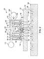
- FIG. 1is a cross-sectional side view of a gas bearing system, a print module package positioned therein, a substrate to be printed on, and a substrate support, in accordance with various embodiments of the present teachings.
- FIG. 2is a cross-sectional side view of a gas bearing system, print module package positioned therein, substrate, and substrate positioning system, in accordance with various embodiments of the present teachings.
- FIG. 3is a bottom, perspective, exploded view of a gas bearing system in accordance with various embodiments of the present teachings.
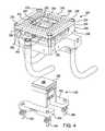
- FIG. 4is a left, bottom, perspective view of the gas bearing system shown in FIG. 3 , in an assembled state, and a print module package to be adjustably mounted therein.
- FIG. 5is a perspective view of the gas bearing system shown in FIG. 3 , upside down and in an assembled state, and a print module package adjustably mounted or secured therein.
- FIG. 6is a right, bottom perspective view of the gas bearing system and print module package shown in FIG. 5 .
- FIG. 7is a perspective view of the gas bearing system and print module package shown in FIGS. 5 and 6 , secured to a rotating actuator and positioned for carrying out a thermal printing operation.
- the gas bearing systemcomprises a housing having a sidewall and the sidewall comprises an exterior surface and an interior surface.
- the sidewalldefines an interior cavity configured to receive a print module package.
- the interior surfacecan terminate at a top, a bottom, or both, and define an opening to the interior cavity.
- the interior cavitycan form a through-hole through the housing or can have only a single opening at one end.
- the sidewallcan also have an end surface between its exterior surface and its interior surface, and the end surface can comprise a first plurality of apertures and a second plurality of apertures.
- a first plurality of fluid channelscan be included in the sidewall and can extend from the first plurality of apertures, into the sidewall, and into fluid communication with a first manifold.
- a second plurality of fluid channelscan be included in the sidewall and can extend from the second plurality of apertures, into the sidewall, and into fluid communication with a second manifold.
- Each of the first manifold and the second manifoldcan independently be internal to the sidewall, external to the sidewall, or both.
- the first manifoldcan be in fluid communication with an environment outside of the housing, for example, via a first port.
- the second manifoldcan be in fluid communication with an environment outside of the housing, for example, via a second port.
- Conduits, such as tubingcan be in fluid communication with each of the manifolds and can be further connected to a supply of pressurized gas, to a vacuum source, or both.
- the first plurality of apertures and the second plurality of aperturescan be arranged to surround the opening to the interior cavity.
- the interior cavitycan have a cross-sectional shape that is square, rectangular, round, or of any other shape.
- the aperturescan surround the opening to the interior cavity on two sides, three sides, four sides, or at least five sides.
- the end surface of the sidewallcan further comprise a third plurality of fluid channels extending into the sidewall and communicating with a third manifold that differs from the first and second manifolds.
- the third manifoldcan be in fluid communication with an environment outside of the housing, for example, via a third port.
- the third manifoldcan be in fluid communication with a source of pressurized gas, a vacuum source, or both.
- the third manifoldcan be in fluid communication with the same source of pressurized gas that is in fluid communication with the first manifold, or in fluid communication with a different source of pressurized gas.
- the individual apertures of the first and second pluralities of aperturescan be spaced apart from adjacent apertures by a mean distance of from about 0.5 mm to about 20 mm, for example, a mean distance of from about 1.0 mm to about 10 mm, of from about 2.0 mm to about 8.0 mm, or of from about 3.0 mm to about 6.0 mm.
- the apertures of the first and second pluralities of aperturescan have a mean diameter of from about 0.001 inch to about 0.1 inch, for example, of from about 0.003 inch to about 0.075 inch, of from about 0.005 inch to about 0.05 inch, or of from about 0.01 inch to about 0.04 inch.
- the first plurality of aperturescan have a mean diameter of from about 0.005 inch to about 0.025 inch and the second plurality of apertures can have a mean diameter of from about 0.030 inch to about 0.090 inch.
- the first plurality of fluid channelscan be in fluid communication with a pressurized gas source and the second plurality of fluid channels can be in fluid communication with a vacuum source.
- the pressurized gas sourcecan comprise a pressurized inert gas source, for example, a source of nitrogen gas, a source of a noble gas, or a combination thereof.
- the housingcan comprise a plurality of components, for example, a base plate, a manifold compartment mounted on the base plate, and a face plate mounted on the manifold.
- the face platecomprises the end surface.
- the base platecan comprise the first and second ports and the manifold compartment can comprise the first and second manifolds.
- the base platecomprises a third port and the manifold compartment comprises a third manifold.
- the base platecan comprise first, second, and third ports and the manifold compartment can comprise first, second, and third manifolds.
- the manifold compartment or one or more of the manifoldscan comprise one or more of the ports.
- a connector flangecan be connected to the base plate and configured for connection to at least one of a support and an actuator.
- One or more of the componentscan define the sidewall or partially define the sidewall, for example, a stack of components including a face plate can together define the sidewall, the interior cavity, or both.
- the housingcan provide a second opening to the interior cavity.
- the second openingcan be located opposite the first opening such that the interior cavity can comprise a through hole that extends through the entire housing.
- At least one print module packagecan be mounted in the interior cavity.
- the at least one print module packagecan comprise at least one inkjet printhead or at least one thermal printing printhead having at least one transfer surface, and at least one heater in thermal communication with the at least one transfer surface.
- the second openingallows exhaust to be vented from the interior cavity. The second opening can enable print module package loading from a top of the system, from a bottom of the system, or both.
- orientation of the gas bearing systemcan be varied and that designations such at top and bottom are intended to be relative and not absolute terms.
- the featuresare reversed such that the second opening can enable the print module package to be loaded from a bottom of the system.
- a print gap control systemcomprises a gas bearing system as described herein, and a substrate comprising a first planar surface.
- the systemcan be configured such that the end surface lies in a first plane, the at least one transfer surface lies in a second plane, and the first planar substrate surface lies in a third plane.
- the first, second, and third planescan be substantially parallel to one another, that is, parallel to one another or skewed by less than 10° or less than 5° with respect to each other.
- a gas bearing gapcan be defined by a distance between the first plane and the third plane.
- a print gapcan be defined by a distance between the second plane and the third plane.
- At least one of the end surface, the inkjet printhead or transfer surface, and the first planar substrate surfacecan be adjustable to control a size of the print gap, a size of the gas bearing gap, or both.
- the print gapcan be controlled independently and/or by controlling the size of the gas bearing gap.
- a gas bearing systemcan be positioned above, below, or above and below the substrate.
- the gas bearing systemcan comprise or be operably associated with one or more actuators to enable adjustment of the position of the gas bearing system relative to the substrate and/or relative to one or more inkjet printheads.
- a second gas bearing systemcan be provided facing the first gas bearing system such that the substrate is positioned between the first gas bearing system and the second gas bearing system.
- the second gas bearing systemcan also comprise a plurality of pressurized gas channels and optionally a plurality of vacuum channels. Pressurized gas channels and vacuum channels can be arranged in any desired configuration. In some embodiments, every other fluid channel or alternating fluid channels comprise a pressurized channel and a vacuum channel.
- the second gas bearingwhich can be mounted in a chuck, can provide temperature control for the substrate. That is, in addition to providing a force to the substrate, the second gas bearing can transfer heat to and/or from the substrate to achieve heating and/or cooling of the substrate.
- Heating channels and cooling channelscan be arranged in any desired configuration.
- every other fluid channelcan comprise a heating channel or a cooling channel.
- alternating fluid channelscomprise a heating channel, a cooling channel, a heating channel, a cooling channel, and so on.
- Thermal controlcan also be used to control the size of the substrate as heat can tend to expand the substrate and cooling can tend to contract the substrate. Maintenance of a constant size is advantageous. Thermal size changes can be particularly significant for larger substrates, for example, thermal size changes are significant for Generation 8 size glass (2.2 m by 2.5 m).
- Uncontrolled thermal change of the substratecan deleteriously affect product quality by shifting, horizontally and/or vertically, the deposition of ink on the substrate.
- the print gapcan have a tolerance of about +/ ⁇ 10 ⁇ m, +/ ⁇ 7 ⁇ m, or +/ ⁇ 5 ⁇ m.
- a methodcomprises positioning a print module package with respect to a substrate and printing a material onto the substrate by using the print module package.
- the positioningcan be accomplished with a gas bearing system as described herein, for example, one comprising a housing wherein the housing defines an interior cavity.
- the sidewallcan have an exterior surface and an interior surface and the print module package can be received within the interior cavity.
- the interior surfacecan terminate at an opening to the interior cavity and the method can comprise mounting the print module package in the interior cavity.
- the sidewallcan further have an end surface between the exterior surface and the interior surface, and the end surface can comprise a first plurality of apertures and a second plurality of apertures.
- the methodcan comprise supplying pressurized gas to and through the first plurality of apertures and drawing a vacuum through the second plurality of apertures.
- the sidewallcan further comprise a first plurality of fluid channels extending from the first plurality of apertures into the sidewall and communicating with a first manifold.
- the sidewallcan comprise a second plurality of fluid channels extending from the second plurality of apertures into the sidewall and communicating with a second manifold.
- the methodcan comprise supplying a pressurized gas to the first manifold and drawing a vacuum on the second manifold.
- the first manifoldcan be in fluid communication with an environment outside of the housing, for example, via a first port
- the second manifoldcan be in fluid communication with an environment outside of the housing, for example, via a second port.
- Tubing, piping, or other conduitscan connect the first and second manifolds with sources of pressurized gas and vacuum, respectively.
- the first plurality of apertures and the second plurality of aperturessurround the opening to the interior cavity.
- the printingcan comprise thermal printing, for example, thermal printing that comprises inkjet printing followed by solids transfer printing by sublimation or evaporation of solids using the print module package.
- thermal printing and print module packagesthat can be used in accordance with the present teachings include those described, for example, in U.S. Patent Application Publications Nos. US 2008/0308307 A1, US 2008/0311307 A1, US 2008/0311289 A1, and US 2006/0115585 A1, which are incorporated herein in their entireties by reference.
- the print module packagecan comprise a printhead transfer surface and/or inkjet nozzle orifice, the substrate can comprise a first surface, and the printhead transfer surface and/or the inkjet nozzle orifice can face the substrate first surface and be spaced apart from one another by a print gap.
- the printhead transfer surfacecan receive ink deposited by inkjet printing, for example, from an inkjet printing subsystem.
- one or more printhead transfer surfacesare rotated to receive ink and/or rotated to face the substrate to be printed.
- one or more inkjet printheadsare rotated to transfer ink to one or more printhead transfer surfaces.
- the gas bearing system and/or printhead transfer surfacecan be positioned above, below, or above and below the substrate during printing.
- the printingcan comprise inkjet printing directly to a substrate.
- the print module packagecan comprise an inkjet printhead.
- the print module packagecan comprise a SAMBA printhead module (FUJIFILM Dimatix, Inc., Santa Clara, Calif.).
- the gas bearing system and/or inkjet printheadcan be positioned above, below, or above and below the substrate during printing.
- the positioning of the gas bearing system relative to the substratecan comprise controlling the size of the print gap by controlling a flow of fluid through at least one of the first and second manifolds.
- the positioningcan comprise maintaining a positive flow of fluid from the first manifold and through the first plurality of fluid channels and maintaining a negative flow of fluid into the second plurality of fluid channels and through the second manifold.
- the positioningcan comprise adjusting the flow of pressurized gas, vacuum, or both, to control the size of the print gap, gas bearing gap, or both.
- a control unitcan be used to effect control of a pressurized gas source, a vacuum source, or both.
- the print gapcan be defined as a distance of from about 5 ⁇ m to about 100 ⁇ m, for example, from about 20 ⁇ m to about 30 ⁇ m, or about 25 ⁇ m.
- the methodcan maintain or provide a print gap by, for example, flowing an inert gas at a pressure of from about 10 psig to about 200 psig, from about 30 psig to about 90 psig, from about 50 psig to about 70 psig, or about 60 psig, through the first plurality of fluid channels.
- the positioningcan further comprise pulling a vacuum through the second plurality of fluid channels at a negative pressure of from about ⁇ 3.0 psig to about ⁇ 13 psig, from about ⁇ 5.0 psig to about ⁇ 10 psig, or about ⁇ 7.5 psig.
- the printingcan comprise printing onto a first surface of a substrate, wherein the substrate has a second surface opposite the first surface, and the method further comprises positioning a second gas bearing system adjacent the second surface of the substrate and opposite the first gas bearing system.
- the second gas bearing systemcan be configured to position the first surface of the substrate and to maintain a desired print gap.
- the second gas bearing systemcan be used instead of, or in addition to, the first gas bearing system.
- Various embodiments of the present teachingsrelate to apparatuses and methods for using air bearings for maintaining and controlling print gap and for controlling the environment surrounding the ink deposition-printing process.
- ink depositioncan be carried out in a non-oxidizing environment.
- the printheadis mounted in a gas bearing housing so that the set gap is fixed at a certain distance, which can be as close to zero mm as practical.
- the set gapcorresponds to the distance between the transfer surface of the printhead and the end surface of the gas bearing housing.
- the gas bearing gapis the distance between the end surface and the substrate. Whether the substrate moves under the printhead and/or the printhead moves over the substrate, either way, there is relative motion between the printhead and the substrate.
- the print gapbecomes the sum of the gas bearing gap and the set gas such that the print gap is controlled by these other two gaps. Fine changes, for example, on the order of microns, can be made to the print gap by changing the gas pressure in the gas bearing housing.
- the flow of gas from the gas bearing housing to the exhaustcreates an environment filled with the bearing gas.
- a non-oxygen gas and/or inert gassuch as nitrogen gas, for example, can be used to provide a non-oxidizing environment.
- the process of evaporating liquid ink within or on the printheadcan cause solvent vapors to be produced.
- the exhaust openingallows both the removal of nitrogen gas injected by the gas bearing system and the removal of the solvent vapors evolved during evaporation of liquid ink.
- pressure and vacuum sourcesare both employed in defining a desired print gap.
- a vacuum source and a nitrogen gas pressure sourceare provided. These sources are disposed for fluid communication with respective channels in a gas bearing housing, for example, disposed about a printhead, and thus a gas bearing gap can be established.
- the print gapcan be variable relative to the bearing housing.
- the gas bearing housing and printheadcan be disposed adjacent a substrate, for example, glass.
- the printheadcan deposit film material, for example, an ink, comprising a film-forming material dissolved or suspended in a carrier fluid, on the substrate.
- the substrateis supported via a chuck with a gas lift or gas bearing system.
- the substrateis supported via a vacuum chuck in contact with the substrate.
- the gas bearing system of the present teachingscan be used alone or in combination with one or more additional gas bearing systems.
- the additional gas bearing systemcan utilize any gas or mixture of gasses.
- the additional gas bearing systemcan use the same or different gas or gaseous mixture as contained in a gas enclosure system, for example, a system that encloses a thermal printing operation.
- air bearingsuse an inert gas, for example, nitrogen gas, one or more noble gasses, or a combination thereof.
- Gas bearing systems, as well as related methods and systems, that can be usedinclude those available from New Way Machine Components, Inc. of Aston, Pa. They can be used alone, or in combination with, the gas bearing systems described in the present teachings.
- Devices, systems, methods, and applications for use relating to gas bearing systemscan be used in connection with the present teachings, including, for example, those described in U.S. Pat. No. 7,908,885 B2, which is incorporated herein in its entirety by reference.
- Gas bearing systems, as well as related methods and systems available from Coreflow Scientific Solutions LTD. of Yoqneam, Israel,can also be used, alone or in combination with the gas bearing systems described in the present teachings.
- Devices, systems, methods, and applications relating to gas bearing systems that can also be used in connection with the present teachingsinclude, for example, those described in U.S. Pat. Nos. 7,857,121 B2, 7,604,439 B2, 7,603,028 B2, and 7,530,778 B2, which are incorporated herein in their entireties by reference.
- FIG. 1is a cross-sectional view of a gas bearing system 20 in accordance with various embodiments of the present teachings.
- Gas bearing system 20comprises a housing 22 that comprises a sidewall 24 .
- Sidewall 24comprises an exterior surface 26 and an interior surface 28 .
- Interior surface 28defines an interior cavity 30 that is configured to receive a print module package 32 .
- Interior surface 28terminates at a cavity opening 34 of interior cavity 30 .
- An end surface 36is disposed between interior surface 28 and exterior surface 26 .
- Opposite end surface 36is an annular end portion 38 comprising a second cavity opening 40 .
- Second cavity opening 40can comprise a through hole 42 .
- a first aperture 44 and a second aperture 46can be located on end surface 36 . Extending from first aperture 44 can be a first fluid channel 48 that extends into sidewall 24 of housing 22 .
- a second fluid channel 50can extend from second aperture 46 into sidewall 24 of housing 22 .
- print module package 32can comprise a transfer surface 52 from which material can be transferred onto a substrate 56 , and more specifically substrate surface 57 , to form a deposited material 54 .
- a print gap 58is defined as the distance between transfer surface 52 and substrate surface 57 .
- a gas bearing gap 60is defined as the distance between end surface 36 and substrate surface 57 .
- a set gap 62is defined as the difference between the gas bearing system gap 60 and print gap 58 , which is the same as the distance between transfer surface 52 and end surface 36 .
- FIG. 2is a schematic, cross-sectional view of a gas bearing system 120 in accordance with various embodiments of the present teachings.
- Gas bearing system 120comprises a housing 122 that in turn comprises a sidewall 124 .
- Sidewall 124comprises an exterior surface 126 and an interior surface 128 defining an interior cavity 130 .
- Interior cavity 130is configured to receive a print module package 132 through a cavity opening 134 .
- Between exterior surface 126 and interior surface 128is an end surface 136 .
- a second cavity opening 138can be located opposite cavity opening 134 .
- End surface 136can comprise a first aperture 140 and a second aperture 142 .
- a first fluid channel 144can extend from first aperture 140 into sidewall 124 of housing 122 .
- a second fluid channel 146can extend from second aperture 142 into sidewall 124 of housing 122 .
- first fluid channel 144 and second fluid channel 146can be in fluid communication with a first manifold 148 .
- End surface 136can further comprise a third aperture 150 , a fourth aperture 152 , a fifth aperture 154 , and a sixth aperture 156 .
- Third fluid channel 158 , fourth fluid channel 160 , fifth fluid channel 162 , and sixth fluid channel 164can extend respectively from third aperture 150 , fourth aperture 152 , fifth aperture 154 , and sixth aperture 156 into sidewall 124 of housing 122 .
- Third fluid channel 158 , fourth fluid channel 160 , fifth fluid channel 162 , and sixth fluid channel 164can be in fluid communication with a second manifold 166 .
- a pressurized gas source 168is in fluid communication with first manifold 148 .
- a vacuum source 170is in fluid communication with second manifold 166 .
- a transfer surface 172 of print module package 132can be configured to deposit a material, for example, a film-forming material, on a substrate. Deposited material 174 can be located on substrate 176 and more specifically on substrate surface 178 .
- a print gap 180can be defined as the distance between transfer surface 172 and substrate surface 178 .
- a gas bearing system gapcan be defined as the distance between end surface 136 and substrate surface 178 .
- a set gapcan be defined as the distance between end surface 136 and transfer surface 172 .
- a second gas bearing system 186is provided. Second gas bearing system 186 can comprise a plurality of apertures 188 in fluid communication with a plurality of fluid channels (not shown). Apertures 188 can face a second substrate surface 190 of substrate 176 .
- FIG. 3is an exploded view of a gas bearing system 220 in accordance with various embodiments of the present teachings.
- Gas bearing system 220can comprise a plurality of fasteners 222 to secure together a face plate 224 , a manifold assembly cover 226 , a manifold assembly base 228 , and a base plate 230 .
- Fasteners 222can comprise a first fastener 232 , a second fastener 234 , a third fastener 236 , and a fourth fastener 238 .
- Face plate 224can comprise an end surface 240 . End surface 240 can receive fasteners 222 .
- Face plate 224can comprise an exterior surface 250 and an interior surface 252 .
- Interior surface 252can define an interior cavity portion 254 as well as a first interior cavity opening 255 .
- a plurality of fluid channel portions 256can be disposed in face plate 224 between interior surface 252 and exterior surface 250 . Each fluid channel portion 256 can terminate at a respective aperture on the end surface of face plate 224 (not shown).
- Manifold assembly cover 226can comprise a first fastener hole portion 258 , a second fastener hole portion 260 , a third fastener hole portion 262 , and a fourth fastener hole portion 264 .
- the fastener hole portionscan be disposed between an exterior surface 266 and an interior surface 268 of manifold assembly cover 226 .
- Interior surface 268can define an interior cavity portion 270 .
- a plurality of fluid channel portions included within a complementary manifold portion 274can be disposed between interior surface 268 and exterior surface 266 .
- Manifold assembly base 228can comprise a first fastener hole portion 276 , a second fastener hole portion 278 , a third fastener hole portion 280 , and a fourth fastener hole portion 282 .
- Fastener hole portions of manifold assembly base 228can be positioned between exterior surface 284 and interior surface 286 of manifold assembly base 228 .
- Interior surface 286can define an interior cavity portion 288 .
- Exterior surface 284 and interior surface 286can also define between them a plurality of fluid channel portions within a complementary manifold portion 292 .
- a port receiving aperture 294can extend from exterior surface 284 .
- Base plate 230can comprise a first port 296 , a second port 298 , and a third port 300 .
- a first fluid line 302can be connected to first port 296 .
- a second fluid line 304can be connected to second port 298 .
- a third fluid line 306can be connected to third port 300 .
- Face plate 230can comprise a main base plate portion 308 .
- Main base plate portion 308can comprise an interior cavity portion 310 as well as a second interior cavity opening 312 .
- An interior base surface 314can face manifold assembly base 228 .
- An exterior base surface 316 of base plate 230can face outwardly in a manner similar but opposite to end surface 240 of face plate 224 .
- a plurality of print module package adjustment screw receiving holescan be disposed in exterior base surface 316 . These can include first print module package adjustment screw receiving hole 318 and a second print module package adjustment screw receiving hole 320 . Other adjustment screw receiving holes can be provided, for example, one for each adjustment screw on a print module package.
- Base plate 230can further comprise a flange 326 . Flange 326 can be configured for attachment, for example, to an actuator, a robotic arm, a rotating actuator, a support piece, or the like.
- Flange 326can comprise a first flange fastener receiving hole 328 , a second flange fastener receiving hole 330 , a third flange fastener receiving hole 332 , and a fourth flange fastener receiving hole 334 .
- FIG. 4is a left, bottom perspective view of gas bearing system 220 shown assembled and adjacent a print module package 336 .
- First fastener 232 , second fastener 234 , third fastener 236 , and fourth fastener 238are shown disposed through end surface 240 and secure together face plate 224 , manifold assembly cover 226 , manifold assembly base 228 , and base plate 230 .
- Print module package 336comprises a printhead 338 as its apex.
- Printhead 338can comprise one or more transfer surfaces 340 .
- Print module package 336can comprise one or more print module package adjustment devices such as linear adjustment screws.
- first print module package adjustment screw 342shows a first print module package adjustment screw 342 , a second print module package adjustment screw 344 , and a third print module package adjustment screw 346 .
- Any number of adjustment screwscan be used, for example, three or four.
- Linear adjustment screwscan be used to align the theta x and y rotation of printhead 338 and/or to make transfer surface 340 of printhead 338 flush, recessed, parallel to, and/or slightly extended from end surface 240 of gas bearing system 220 .
- First print module package adjustment screw 342 and second print module package adjustment screw 344can be secured to, mounted in, and/or adjustably disposed in first print module package base flange 350 .
- Third print module package adjustment screw 346 and one or more other print module package adjustment screwscan be secured to, mounted in, and/or adjustably disposed in second print module base flange 352 .
- Print module package 336can be fastened to gas bearing system 220 using any of a variety of fasteners.
- two magnets 322 and 324are shown mounted in the underside of base plate 230 .
- Magnets 322 and 324can be aligned with corresponding magnets (not shown) on print module package 336 or aligned with a magnetically susceptible metal material that is a part of print module package 336 , for example, base flanges 350 and 352 shown in FIG. 4 . Any number of magnets can be used.
- Interior cavity 354can result from the assembly of gas bearing system 220 including interior cavity portion 254 , interior cavity opening 255 , interior cavity portion 288 ( FIG. 3 ), and interior cavity portion 310 ( FIG. 3 ).
- a plurality of apertures 360are shown disposed on end surface 240 between exterior surface 250 and interior surface 252 .
- a plurality of manifolds 362are contained within manifold assembly cover 226 and manifold assembly base 228 .
- FIG. 5is a perspective view of gas bearing system 220 upside down, and assembled with a print module package 336 .
- Print module package 336has been placed into interior cavity 354 and first print module package adjustment screw 342 , second print module package adjustment screw 344 , and third print module package adjustment screw 346 are utilized to adjust the relative positioning between print module package 336 and gas bearing system 220 .
- This configurationpresses first print module package base flange 350 and second print module package base flange 352 against exterior base surface 316 of base plate 230 .
- FIG. 6is a right, bottom perspective view of gas bearing system 220 and print module package 336 in an assembled configuration.
- Printhead 338 and transfer surface 340are visible through first interior cavity opening 255 and are surrounded by the plurality of apertures 360 disposed on end surface 240 .
- FIG. 7is a perspective view of gas bearing system 220 , connected to an actuator 364 through flange 326 .
- Actuator 364can comprise an actuator motor 366 and a rotatable actuator faceplate 368 .
- Flange 326can be secured to actuator face plate 368 .
- Load-lock features and methods of using themthat can be utilized in accordance with various embodiments of the present teachings, include those described, for example, in U.S. Patent Application Publication No. US 2010/0201749 A1, which is incorporated herein in its entirety by reference.
Landscapes
- Engineering & Computer Science (AREA)
- Manufacturing & Machinery (AREA)
- Coating Apparatus (AREA)
- Particle Formation And Scattering Control In Inkjet Printers (AREA)
- Physics & Mathematics (AREA)
- Ink Jet (AREA)
- Mathematical Physics (AREA)
- General Engineering & Computer Science (AREA)
- General Physics & Mathematics (AREA)
- Theoretical Computer Science (AREA)
- Electroluminescent Light Sources (AREA)
Abstract
Description
Claims (14)
Priority Applications (16)
| Application Number | Priority Date | Filing Date | Title |
|---|---|---|---|
| US13/570,154US9120344B2 (en) | 2011-08-09 | 2012-08-08 | Apparatus and method for control of print gap |
| KR1020217038157AKR102377885B1 (en) | 2012-08-08 | 2013-10-02 | Method for control of print gap |
| KR1020177018730AKR101967080B1 (en) | 2012-08-08 | 2013-10-02 | Apparatus and method for control of print gap |
| KR1020217025326AKR102332376B1 (en) | 2012-08-08 | 2013-10-02 | Method for control of print gap |
| KR1020207025819AKR102290642B1 (en) | 2012-08-08 | 2013-10-02 | Method for control of print gap |
| KR1020157003107AKR101757993B1 (en) | 2012-08-08 | 2013-10-02 | Apparatus and method for control of print gap |
| KR1020197009314AKR102155975B1 (en) | 2012-08-08 | 2013-10-02 | Method for control of print gap |
| KR1020227008892AKR20220039837A (en) | 2012-08-08 | 2013-10-02 | Printing system |
| KR1020177018732AKR101967081B1 (en) | 2012-08-08 | 2013-10-02 | Method for control of print gap |
| PCT/US2013/063128WO2014026205A2 (en) | 2012-08-08 | 2013-10-02 | Apparatus and method for control of print gap |
| US14/807,628US9302513B2 (en) | 2011-08-09 | 2015-07-23 | Apparatus and method for control of print gap |
| US15/080,407US9550383B2 (en) | 2011-08-09 | 2016-03-24 | Apparatus and method for control of print gap |
| US15/385,803US9789715B2 (en) | 2011-08-09 | 2016-12-20 | Apparatus and method for control of print gap |
| US15/423,169US9656491B1 (en) | 2011-08-09 | 2017-02-02 | Apparatus and method for control of print gap |
| US15/594,856US10029497B2 (en) | 2011-08-09 | 2017-05-15 | Apparatus and method for control of print gap |
| US16/040,138US20180326767A1 (en) | 2011-08-09 | 2018-07-19 | Apparatus and Method for Control of Print Gap |
Applications Claiming Priority (2)
| Application Number | Priority Date | Filing Date | Title |
|---|---|---|---|
| US201161521604P | 2011-08-09 | 2011-08-09 | |
| US13/570,154US9120344B2 (en) | 2011-08-09 | 2012-08-08 | Apparatus and method for control of print gap |
Related Child Applications (1)
| Application Number | Title | Priority Date | Filing Date |
|---|---|---|---|
| US14/807,628DivisionUS9302513B2 (en) | 2011-08-09 | 2015-07-23 | Apparatus and method for control of print gap |
Publications (2)
| Publication Number | Publication Date |
|---|---|
| US20130038649A1 US20130038649A1 (en) | 2013-02-14 |
| US9120344B2true US9120344B2 (en) | 2015-09-01 |
Family
ID=47677274
Family Applications (7)
| Application Number | Title | Priority Date | Filing Date |
|---|---|---|---|
| US13/570,154Expired - Fee RelatedUS9120344B2 (en) | 2011-08-09 | 2012-08-08 | Apparatus and method for control of print gap |
| US14/807,628ActiveUS9302513B2 (en) | 2011-08-09 | 2015-07-23 | Apparatus and method for control of print gap |
| US15/080,407ActiveUS9550383B2 (en) | 2011-08-09 | 2016-03-24 | Apparatus and method for control of print gap |
| US15/385,803ActiveUS9789715B2 (en) | 2011-08-09 | 2016-12-20 | Apparatus and method for control of print gap |
| US15/423,169ActiveUS9656491B1 (en) | 2011-08-09 | 2017-02-02 | Apparatus and method for control of print gap |
| US15/594,856ActiveUS10029497B2 (en) | 2011-08-09 | 2017-05-15 | Apparatus and method for control of print gap |
| US16/040,138AbandonedUS20180326767A1 (en) | 2011-08-09 | 2018-07-19 | Apparatus and Method for Control of Print Gap |
Family Applications After (6)
| Application Number | Title | Priority Date | Filing Date |
|---|---|---|---|
| US14/807,628ActiveUS9302513B2 (en) | 2011-08-09 | 2015-07-23 | Apparatus and method for control of print gap |
| US15/080,407ActiveUS9550383B2 (en) | 2011-08-09 | 2016-03-24 | Apparatus and method for control of print gap |
| US15/385,803ActiveUS9789715B2 (en) | 2011-08-09 | 2016-12-20 | Apparatus and method for control of print gap |
| US15/423,169ActiveUS9656491B1 (en) | 2011-08-09 | 2017-02-02 | Apparatus and method for control of print gap |
| US15/594,856ActiveUS10029497B2 (en) | 2011-08-09 | 2017-05-15 | Apparatus and method for control of print gap |
| US16/040,138AbandonedUS20180326767A1 (en) | 2011-08-09 | 2018-07-19 | Apparatus and Method for Control of Print Gap |
Country Status (3)
| Country | Link |
|---|---|
| US (7) | US9120344B2 (en) |
| KR (6) | KR101967080B1 (en) |
| WO (1) | WO2014026205A2 (en) |
Cited By (2)
| Publication number | Priority date | Publication date | Assignee | Title |
|---|---|---|---|---|
| US9656491B1 (en) | 2011-08-09 | 2017-05-23 | Kateeva, Inc. | Apparatus and method for control of print gap |
| US10280024B2 (en)* | 2016-01-11 | 2019-05-07 | Boe Technology Group Co., Ltd. | Film feeding apparatus and control method thereof |
Families Citing this family (33)
| Publication number | Priority date | Publication date | Assignee | Title |
|---|---|---|---|---|
| US12064979B2 (en) | 2008-06-13 | 2024-08-20 | Kateeva, Inc. | Low-particle gas enclosure systems and methods |
| US9604245B2 (en) | 2008-06-13 | 2017-03-28 | Kateeva, Inc. | Gas enclosure systems and methods utilizing an auxiliary enclosure |
| US10442226B2 (en) | 2008-06-13 | 2019-10-15 | Kateeva, Inc. | Gas enclosure assembly and system |
| US9048344B2 (en) | 2008-06-13 | 2015-06-02 | Kateeva, Inc. | Gas enclosure assembly and system |
| US12018857B2 (en) | 2008-06-13 | 2024-06-25 | Kateeva, Inc. | Gas enclosure assembly and system |
| US8899171B2 (en)* | 2008-06-13 | 2014-12-02 | Kateeva, Inc. | Gas enclosure assembly and system |
| US8383202B2 (en) | 2008-06-13 | 2013-02-26 | Kateeva, Inc. | Method and apparatus for load-locked printing |
| US10434804B2 (en) | 2008-06-13 | 2019-10-08 | Kateeva, Inc. | Low particle gas enclosure systems and methods |
| US11975546B2 (en) | 2008-06-13 | 2024-05-07 | Kateeva, Inc. | Gas enclosure assembly and system |
| CN106299116B (en) | 2011-08-09 | 2019-07-12 | 科迪华公司 | Printing device and method downwards |
| CN109130549B (en)* | 2013-03-13 | 2021-02-26 | 科迪华公司 | Gas enclosure system and method of using auxiliary enclosure |
| CN105431294B (en)* | 2013-06-10 | 2018-04-24 | 科迪华公司 | Low particulate gas containment systems and methods |
| US10468279B2 (en) | 2013-12-26 | 2019-11-05 | Kateeva, Inc. | Apparatus and techniques for thermal treatment of electronic devices |
| KR102307190B1 (en) | 2014-01-21 | 2021-09-30 | 카티바, 인크. | Apparatus and techniques for electronic device encapsulation |
| US9343678B2 (en) | 2014-01-21 | 2016-05-17 | Kateeva, Inc. | Apparatus and techniques for electronic device encapsulation |
| EP3882961B1 (en) | 2014-04-30 | 2023-07-26 | Kateeva, Inc. | Gas cushion apparatus and techniques for substrate coating |
| US11220737B2 (en)* | 2014-06-25 | 2022-01-11 | Universal Display Corporation | Systems and methods of modulating flow during vapor jet deposition of organic materials |
| US11267012B2 (en)* | 2014-06-25 | 2022-03-08 | Universal Display Corporation | Spatial control of vapor condensation using convection |
| EP2960059B1 (en)* | 2014-06-25 | 2018-10-24 | Universal Display Corporation | Systems and methods of modulating flow during vapor jet deposition of organic materials |
| WO2016086192A1 (en) | 2014-11-26 | 2016-06-02 | Kateeva, Inc. | Environmentally controlled coating systems |
| US10704144B2 (en) | 2015-10-12 | 2020-07-07 | Universal Display Corporation | Apparatus and method for printing multilayer organic thin films from vapor phase in an ultra-pure gas ambient |
| US10566534B2 (en) | 2015-10-12 | 2020-02-18 | Universal Display Corporation | Apparatus and method to deliver organic material via organic vapor-jet printing (OVJP) |
| CN106079897B (en)* | 2016-06-28 | 2017-12-19 | 纳晶科技股份有限公司 | Inkjet-printing device and inkjet printing methods |
| JP6803177B2 (en) | 2016-08-29 | 2020-12-23 | 株式会社日本製鋼所 | Laser irradiation device |
| US10964624B2 (en) | 2017-01-26 | 2021-03-30 | Intel Corporation | Techniques for fluid cooling of integrated circuits in packages |
| US10422038B2 (en)* | 2017-03-14 | 2019-09-24 | Eastman Kodak Company | Dual gas bearing substrate positioning system |
| CN107672311B (en)* | 2017-10-11 | 2019-05-31 | 江苏正华包装有限公司 | A kind of food packaging automatic code-spraying equipment |
| TWI812812B (en) | 2018-12-20 | 2023-08-21 | 美商凱特伊夫公司 | An inkjet printer and a method of depositing material on a substrate using a temperature controlled substrate support |
| US11088325B2 (en) | 2019-01-18 | 2021-08-10 | Universal Display Corporation | Organic vapor jet micro-print head with multiple gas distribution orifice plates |
| CN113905828B (en) | 2019-05-31 | 2023-11-14 | 科迪华公司 | Printer calibration module |
| JP7313210B2 (en)* | 2019-06-28 | 2023-07-24 | 東京エレクトロン株式会社 | Droplet ejection device |
| EP4049091A4 (en)* | 2019-10-25 | 2023-11-22 | Evolve Additive Solutions, Inc. | COOLING APPARATUS AND ADDITIVE MANUFACTURING METHOD |
| KR20230038383A (en) | 2021-09-10 | 2023-03-20 | 임채환 | Map word development and implementation process 1 |
Citations (62)
| Publication number | Priority date | Publication date | Assignee | Title |
|---|---|---|---|---|
| US3216858A (en) | 1963-04-26 | 1965-11-09 | Cons Edison Co New York Inc | Method of purging gas-conduit tubing in gas-filled electric cables |
| US3498343A (en) | 1966-12-13 | 1970-03-03 | Lawrence R Sperberg | Apparatus for inflating pneumatic tires with an inert gas |
| US3670466A (en) | 1970-08-03 | 1972-06-20 | Metal Products Corp | Insulated panel |
| US3885362A (en) | 1973-04-19 | 1975-05-27 | Gordon J Pollock | Modular noise abatement enclosure and joint seal |
| US4226897A (en) | 1977-12-05 | 1980-10-07 | Plasma Physics Corporation | Method of forming semiconducting materials and barriers |
| US4581478A (en) | 1982-04-07 | 1986-04-08 | Pugh Paul F | Gas pressurized cable and conduit system |
| US5029518A (en) | 1989-10-16 | 1991-07-09 | Clean Air Technology, Inc. | Modular clean room structure |
| US5065169A (en)* | 1988-03-21 | 1991-11-12 | Hewlett-Packard Company | Device to assure paper flatness and pen-to-paper spacing during printing |
| US5314377A (en) | 1992-10-05 | 1994-05-24 | Airo Clean Inc. | Clean air isolation enclosure |
| US5344365A (en) | 1993-09-14 | 1994-09-06 | Sematech, Inc. | Integrated building and conveying structure for manufacturing under ultraclean conditions |
| US5896154A (en) | 1993-04-16 | 1999-04-20 | Hitachi Koki Co., Ltd. | Ink jet printer |
| US6023899A (en) | 1998-11-03 | 2000-02-15 | Climatecraft Technologies, Inc. | Wall panel assembly with airtight joint |
| US6049167A (en) | 1997-02-17 | 2000-04-11 | Tdk Corporation | Organic electroluminescent display device, and method and system for making the same |
| US6086679A (en) | 1997-10-24 | 2000-07-11 | Quester Technology, Inc. | Deposition systems and processes for transport polymerization and chemical vapor deposition |
| US6089282A (en) | 1998-05-08 | 2000-07-18 | Aeronex, Inc. | Method for recovery and reuse of gas |
| US20020033860A1 (en) | 2000-06-01 | 2002-03-21 | Hidemi Kubota | Inkjet recording apparatus |
| US6375304B1 (en) | 2000-02-17 | 2002-04-23 | Lexmark International, Inc. | Maintenance mist control |
| US20020079057A1 (en) | 1999-10-08 | 2002-06-27 | Ken Yoshioka | Apparatus for processing specimens |
| US20020084464A1 (en) | 2000-12-12 | 2002-07-04 | Shunpei Yamazaki | Light emitting device and method of manufacturing the same |
| US6437351B1 (en) | 1997-09-10 | 2002-08-20 | Applied Materials, Inc. | Method and apparatus for controlling a workpiece in a vacuum chamber |
| US20020124906A1 (en) | 2000-12-04 | 2002-09-12 | Yoko Suzuki | Substrate transport apparatus, POD and method |
| US20030000476A1 (en) | 2001-06-28 | 2003-01-02 | Hitachi Kokusai Electric Inc. | Substrate processing apparatus, conveying unit thereof, and semiconductor device fabricating Method |
| US20030097929A1 (en) | 2001-10-31 | 2003-05-29 | Tadaharu Watanabe | Materials and method for the purification of hydride gases |
| US20030175414A1 (en) | 2002-01-23 | 2003-09-18 | Seiko Epson Corporation | Method of, and apparatus for, manufacturing organic EL device; organic EL device; electronic device; and liquid droplet ejection apparatus |
| CN1445089A (en) | 2002-03-15 | 2003-10-01 | 精工爱普生株式会社 | Through structure of sealed chamber connecting pipeline, device with the structure and its making method |
| US20040009304A1 (en) | 2002-07-09 | 2004-01-15 | Osram Opto Semiconductors Gmbh & Co. Ogh | Process and tool with energy source for fabrication of organic electronic devices |
| US20040054774A1 (en) | 2002-05-04 | 2004-03-18 | Instant802 Networks Inc. | Using wireless network access points for monitoring radio spectrum traffic and interference |
| US20040050325A1 (en) | 2002-09-12 | 2004-03-18 | Samoilov Arkadii V. | Apparatus and method for delivering process gas to a substrate processing system |
| US20040086631A1 (en) | 2002-10-25 | 2004-05-06 | Yu-Kai Han | Ink jet printing device and method |
| US20040115339A1 (en) | 2002-09-19 | 2004-06-17 | Nobuyuki Ito | Method and apparatus for manufacturing organic EL display and color filter by ink jet method |
| US20040123804A1 (en) | 2002-09-20 | 2004-07-01 | Semiconductor Energy Laboratory Co., Ltd. | Fabrication system and manufacturing method of light emitting device |
| US20050005850A1 (en) | 1999-07-23 | 2005-01-13 | Semiconductor Energy Laboratory Co., Ltd. | Method of fabricating an EL display device, and apparatus for forming a thin film |
| US20050062773A1 (en) | 2001-07-20 | 2005-03-24 | Gemplus | Pressure regulation by transfer of a calibrated gas volume |
| US20050140764A1 (en) | 2003-12-31 | 2005-06-30 | Ritdisplay Corporation | Ink-jet printing apparatus |
| US20050223994A1 (en) | 2004-04-08 | 2005-10-13 | Blomiley Eric R | Substrate susceptors for receiving semiconductor substrates to be deposited upon and methods of depositing materials over semiconductor substrates |
| WO2006021568A1 (en) | 2004-08-24 | 2006-03-02 | Otb Groep B.V. | In-line process for making thin film electronic devices |
| US7023013B2 (en) | 2004-06-16 | 2006-04-04 | Eastman Kodak Company | Array of light-emitting OLED microcavity pixels |
| US20060099328A1 (en) | 2002-09-26 | 2006-05-11 | Waite Michael S | Creating layers in thin-film structures |
| US20060219605A1 (en) | 2004-11-08 | 2006-10-05 | Devitt Andrew J | Non-contact porous air bearing and glass flattening device |
| US20060236938A1 (en) | 2005-04-26 | 2006-10-26 | Powell Ricky C | System and method for depositing a material on a substrate |
| US20070044713A1 (en) | 2005-08-24 | 2007-03-01 | Motohiro Yasui | Film Forming Apparatus, Film Forming Method And Method For Manufacturing Piezoelectric Actuator |
| US20070257033A1 (en) | 2006-04-27 | 2007-11-08 | Tokyo Electron Limited | Seal member, depressurized chamber, depressurizing processing apparatus, seal mechanism of depressurized chamber, and method of manufacturing a depressurized chamber |
| US7326300B2 (en) | 2004-07-09 | 2008-02-05 | Innolux Display Corp. | Coating apparatus and method using the same |
| US20080241587A1 (en) | 2004-03-29 | 2008-10-02 | Tadahiro Ohmi | Film-Forming Apparatus And Film-Forming Method |
| US20080308037A1 (en) | 2007-06-14 | 2008-12-18 | Massachusetts Institute Of Technology | Method and apparatus for thermal jet printing |
| US20090031579A1 (en)* | 2007-07-31 | 2009-02-05 | Piatt Michael J | Micro-structured drying for inkjet printers |
| US20090078204A1 (en) | 2007-09-26 | 2009-03-26 | Kerr Roger S | Deposition system for thin film formation |
| US20090081885A1 (en) | 2007-09-26 | 2009-03-26 | Levy David H | Deposition system for thin film formation |
| US7703911B2 (en) | 2003-11-17 | 2010-04-27 | Samsung Electronics Co., Ltd. | Apparatus for forming a thin film using an inkjet printing method |
| US20100182359A1 (en) | 2009-01-20 | 2010-07-22 | Sung-Wook Kim | Ink jet head and ink supplying method thereof |
| US20100201749A1 (en) | 2008-06-13 | 2010-08-12 | Kateeva, Inc. | Method And Apparatus for Load-Locked Printing |
| US20110008541A1 (en)* | 2009-05-01 | 2011-01-13 | Kateeva, Inc. | Method and apparatus for organic vapor printing |
| US20110043554A1 (en) | 2009-08-21 | 2011-02-24 | Silverbrook Research Pty Ltd | Continuous web printer for printing non-identical copies within a print run |
| US20110096124A1 (en) | 2009-10-22 | 2011-04-28 | Silverbrook Research Pty Ltd | Inkjet printhead having low-loss contact for thermal actuators |
| US20110318503A1 (en) | 2010-06-29 | 2011-12-29 | Christian Adams | Plasma enhanced materials deposition system |
| US20120056923A1 (en) | 2009-01-05 | 2012-03-08 | Kateeva, Inc. | Control systems and methods for thermal-jet printing |
| US20130004656A1 (en) | 2011-07-01 | 2013-01-03 | Kateeva, Inc. | Apparatus and method to separate carrier liquid vapor from ink |
| US20130040061A1 (en) | 2011-08-09 | 2013-02-14 | Kateeva, Inc. | Face-down printing apparatus and method |
| US20130038649A1 (en) | 2011-08-09 | 2013-02-14 | Kateeva, Inc. | Apparatus and method for control of print gap |
| US8414688B1 (en) | 2011-06-15 | 2013-04-09 | Kla-Tencor Corporation | Recirculation high purity system for protecting optical modules or inspection system during storage, transport and shipping |
| US20130206058A1 (en) | 2008-06-13 | 2013-08-15 | Kateeva, Inc. | Gas enclosure assembly and system |
| US20130252533A1 (en) | 2008-06-13 | 2013-09-26 | Kateeva, Inc. | Gas Enclosure Assembly and System |
Family Cites Families (33)
| Publication number | Priority date | Publication date | Assignee | Title |
|---|---|---|---|---|
| DE60011764T2 (en) | 1999-04-07 | 2005-07-07 | Mv Research Ltd. | WERKSTOFFPRÜFUNG |
| TW513617B (en)* | 1999-04-21 | 2002-12-11 | Asml Corp | Lithographic projection apparatus and method of manufacturing a device using a lithographic projection apparatus |
| US6781684B1 (en) | 2000-11-07 | 2004-08-24 | Donald L. Ekhoff | Workpiece levitation using alternating positive and negative pressure flows |
| US6939212B1 (en) | 2001-12-21 | 2005-09-06 | Lam Research Corporation | Porous material air bearing platen for chemical mechanical planarization |
| TWI222423B (en) | 2001-12-27 | 2004-10-21 | Orbotech Ltd | System and methods for conveying and transporting levitated articles |
| US7081912B2 (en) | 2002-03-11 | 2006-07-25 | Seiko Epson Corporation | Optical writing head such as organic EL array exposure head, method of manufacturing the same, and image forming apparatus using the same |
| JP3705242B2 (en) | 2002-06-03 | 2005-10-12 | 富士電機ホールディングス株式会社 | Organic EL device manufacturing system |
| JP4378950B2 (en) | 2002-12-24 | 2009-12-09 | セイコーエプソン株式会社 | Droplet ejection apparatus and electro-optic device manufacturing method |
| US7077019B2 (en) | 2003-08-08 | 2006-07-18 | Photon Dynamics, Inc. | High precision gas bearing split-axis stage for transport and constraint of large flat flexible media during processing |
| KR101193201B1 (en) | 2003-11-18 | 2012-10-19 | 삼성디스플레이 주식회사 | Electroluminescent devices and methods of making electroluminescent devices including a color conversion element |
| US7641631B2 (en) | 2004-02-17 | 2010-01-05 | Scimed Life Systems, Inc. | Dilatation balloon having a valved opening and related catheters and methods |
| CN101124133A (en) | 2004-04-14 | 2008-02-13 | 科福罗科学解决方案有限公司 | Non-contact support platform for distance adjustment |
| US7288469B2 (en) | 2004-12-03 | 2007-10-30 | Eastman Kodak Company | Methods and apparatuses for forming an article |
| JP4691975B2 (en) | 2004-12-08 | 2011-06-01 | セイコーエプソン株式会社 | Work gap adjustment method, work gap adjustment device, droplet discharge device, and electro-optical device manufacturing method |
| EP1825332A1 (en) | 2004-12-14 | 2007-08-29 | Radove GmbH | Process and apparatus for the production of collimated uv rays for photolithographic transfer |
| KR100685806B1 (en)* | 2005-01-17 | 2007-02-22 | 삼성에스디아이 주식회사 | Deposition equipment |
| US8298336B2 (en) | 2005-04-01 | 2012-10-30 | Lam Research Corporation | High strip rate downstream chamber |
| KR100700655B1 (en)* | 2005-04-12 | 2007-03-27 | 삼성에스디아이 주식회사 | Deposition equipment |
| WO2007016688A1 (en) | 2005-08-02 | 2007-02-08 | New Way Machine Components, Inc. | A method and a device for depositing a film of material or otherwise processing or inspecting, a substrate as it passes through a vacuum environment guided by a plurality of opposing and balanced air bearing lands and sealed by differentially pumped groves and sealing lands in a non-contact manner |
| US7524226B2 (en) | 2006-10-10 | 2009-04-28 | Eastman Kodak Company | OLED display device with adjusted filter array |
| JP2008161750A (en)* | 2006-12-27 | 2008-07-17 | Seiko Epson Corp | Droplet ejection apparatus and device manufacturing method |
| US20080259101A1 (en) | 2007-03-23 | 2008-10-23 | Applied Materials, Inc. | Methods and apparatus for minimizing the number of print passes in flat panel display manufacturing |
| JP4561795B2 (en) | 2007-08-30 | 2010-10-13 | セイコーエプソン株式会社 | Suction device, droplet discharge device including the same, and method of manufacturing electro-optical device |
| ES2713862T3 (en) | 2008-04-22 | 2019-05-24 | Vladislav Yurievich Mirchev | Method for curing a substance, device for performing said method and ink |
| US9604245B2 (en) | 2008-06-13 | 2017-03-28 | Kateeva, Inc. | Gas enclosure systems and methods utilizing an auxiliary enclosure |
| US20100188457A1 (en) | 2009-01-05 | 2010-07-29 | Madigan Connor F | Method and apparatus for controlling the temperature of an electrically-heated discharge nozzle |
| GB0914856D0 (en) | 2009-08-25 | 2009-09-30 | Ark Therapeutics Ltd | Compounds |
| US20110097494A1 (en) | 2009-10-27 | 2011-04-28 | Kerr Roger S | Fluid conveyance system including flexible retaining mechanism |
| JP5548426B2 (en)* | 2009-10-29 | 2014-07-16 | 株式会社日立製作所 | Inkjet coating apparatus and method |
| JP2011225355A (en) | 2010-04-22 | 2011-11-10 | Sumitomo Heavy Ind Ltd | Air floating unit, stage device, inspection system, exposure system, and application system |
| EP2567257B1 (en) | 2010-05-06 | 2021-03-24 | Immunolight, Llc. | Adhesive bonding composition and method of use |
| KR101871694B1 (en) | 2010-07-01 | 2018-06-27 | 더 리젠츠 오브 더 유니버시티 오브 미시건 | Gas cushion control of ovjp print head position |
| TW201232125A (en) | 2010-12-04 | 2012-08-01 | 3M Innovative Properties Co | Illumination assembly and method of forming same |
- 2012
- 2012-08-08USUS13/570,154patent/US9120344B2/ennot_activeExpired - Fee Related
- 2013
- 2013-10-02KRKR1020177018730Apatent/KR101967080B1/ennot_activeExpired - Fee Related
- 2013-10-02KRKR1020217025326Apatent/KR102332376B1/ennot_activeExpired - Fee Related
- 2013-10-02KRKR1020207025819Apatent/KR102290642B1/ennot_activeExpired - Fee Related
- 2013-10-02WOPCT/US2013/063128patent/WO2014026205A2/enactiveApplication Filing
- 2013-10-02KRKR1020197009314Apatent/KR102155975B1/ennot_activeExpired - Fee Related
- 2013-10-02KRKR1020157003107Apatent/KR101757993B1/ennot_activeExpired - Fee Related
- 2013-10-02KRKR1020177018732Apatent/KR101967081B1/ennot_activeExpired - Fee Related
- 2015
- 2015-07-23USUS14/807,628patent/US9302513B2/enactiveActive
- 2016
- 2016-03-24USUS15/080,407patent/US9550383B2/enactiveActive
- 2016-12-20USUS15/385,803patent/US9789715B2/enactiveActive
- 2017
- 2017-02-02USUS15/423,169patent/US9656491B1/enactiveActive
- 2017-05-15USUS15/594,856patent/US10029497B2/enactiveActive
- 2018
- 2018-07-19USUS16/040,138patent/US20180326767A1/ennot_activeAbandoned
Patent Citations (73)
| Publication number | Priority date | Publication date | Assignee | Title |
|---|---|---|---|---|
| US3216858A (en) | 1963-04-26 | 1965-11-09 | Cons Edison Co New York Inc | Method of purging gas-conduit tubing in gas-filled electric cables |
| US3498343A (en) | 1966-12-13 | 1970-03-03 | Lawrence R Sperberg | Apparatus for inflating pneumatic tires with an inert gas |
| US3670466A (en) | 1970-08-03 | 1972-06-20 | Metal Products Corp | Insulated panel |
| US3885362A (en) | 1973-04-19 | 1975-05-27 | Gordon J Pollock | Modular noise abatement enclosure and joint seal |
| US4226897A (en) | 1977-12-05 | 1980-10-07 | Plasma Physics Corporation | Method of forming semiconducting materials and barriers |
| US4581478A (en) | 1982-04-07 | 1986-04-08 | Pugh Paul F | Gas pressurized cable and conduit system |
| US5065169A (en)* | 1988-03-21 | 1991-11-12 | Hewlett-Packard Company | Device to assure paper flatness and pen-to-paper spacing during printing |
| US5029518A (en) | 1989-10-16 | 1991-07-09 | Clean Air Technology, Inc. | Modular clean room structure |
| US5314377A (en) | 1992-10-05 | 1994-05-24 | Airo Clean Inc. | Clean air isolation enclosure |
| US5896154A (en) | 1993-04-16 | 1999-04-20 | Hitachi Koki Co., Ltd. | Ink jet printer |
| US5344365A (en) | 1993-09-14 | 1994-09-06 | Sematech, Inc. | Integrated building and conveying structure for manufacturing under ultraclean conditions |
| US6049167A (en) | 1997-02-17 | 2000-04-11 | Tdk Corporation | Organic electroluminescent display device, and method and system for making the same |
| US6437351B1 (en) | 1997-09-10 | 2002-08-20 | Applied Materials, Inc. | Method and apparatus for controlling a workpiece in a vacuum chamber |
| US6086679A (en) | 1997-10-24 | 2000-07-11 | Quester Technology, Inc. | Deposition systems and processes for transport polymerization and chemical vapor deposition |
| US6089282A (en) | 1998-05-08 | 2000-07-18 | Aeronex, Inc. | Method for recovery and reuse of gas |
| US6023899A (en) | 1998-11-03 | 2000-02-15 | Climatecraft Technologies, Inc. | Wall panel assembly with airtight joint |
| US20050005850A1 (en) | 1999-07-23 | 2005-01-13 | Semiconductor Energy Laboratory Co., Ltd. | Method of fabricating an EL display device, and apparatus for forming a thin film |
| US7258768B2 (en) | 1999-07-23 | 2007-08-21 | Semiconductor Energy Laboratory Co., Ltd. | Method of fabricating an EL display device, and apparatus for forming a thin film |
| US20020079057A1 (en) | 1999-10-08 | 2002-06-27 | Ken Yoshioka | Apparatus for processing specimens |
| US6375304B1 (en) | 2000-02-17 | 2002-04-23 | Lexmark International, Inc. | Maintenance mist control |
| US20020033860A1 (en) | 2000-06-01 | 2002-03-21 | Hidemi Kubota | Inkjet recording apparatus |
| US20020124906A1 (en) | 2000-12-04 | 2002-09-12 | Yoko Suzuki | Substrate transport apparatus, POD and method |
| US20020084464A1 (en) | 2000-12-12 | 2002-07-04 | Shunpei Yamazaki | Light emitting device and method of manufacturing the same |
| US20030000476A1 (en) | 2001-06-28 | 2003-01-02 | Hitachi Kokusai Electric Inc. | Substrate processing apparatus, conveying unit thereof, and semiconductor device fabricating Method |
| US20050062773A1 (en) | 2001-07-20 | 2005-03-24 | Gemplus | Pressure regulation by transfer of a calibrated gas volume |
| US20030097929A1 (en) | 2001-10-31 | 2003-05-29 | Tadaharu Watanabe | Materials and method for the purification of hydride gases |
| US20030175414A1 (en) | 2002-01-23 | 2003-09-18 | Seiko Epson Corporation | Method of, and apparatus for, manufacturing organic EL device; organic EL device; electronic device; and liquid droplet ejection apparatus |
| CN1445089A (en) | 2002-03-15 | 2003-10-01 | 精工爱普生株式会社 | Through structure of sealed chamber connecting pipeline, device with the structure and its making method |
| US20040054774A1 (en) | 2002-05-04 | 2004-03-18 | Instant802 Networks Inc. | Using wireless network access points for monitoring radio spectrum traffic and interference |
| US20040009304A1 (en) | 2002-07-09 | 2004-01-15 | Osram Opto Semiconductors Gmbh & Co. Ogh | Process and tool with energy source for fabrication of organic electronic devices |
| US20040050325A1 (en) | 2002-09-12 | 2004-03-18 | Samoilov Arkadii V. | Apparatus and method for delivering process gas to a substrate processing system |
| US20040115339A1 (en) | 2002-09-19 | 2004-06-17 | Nobuyuki Ito | Method and apparatus for manufacturing organic EL display and color filter by ink jet method |
| US20040123804A1 (en) | 2002-09-20 | 2004-07-01 | Semiconductor Energy Laboratory Co., Ltd. | Fabrication system and manufacturing method of light emitting device |
| US20060099328A1 (en) | 2002-09-26 | 2006-05-11 | Waite Michael S | Creating layers in thin-film structures |
| US20040086631A1 (en) | 2002-10-25 | 2004-05-06 | Yu-Kai Han | Ink jet printing device and method |
| US7703911B2 (en) | 2003-11-17 | 2010-04-27 | Samsung Electronics Co., Ltd. | Apparatus for forming a thin film using an inkjet printing method |
| US20050140764A1 (en) | 2003-12-31 | 2005-06-30 | Ritdisplay Corporation | Ink-jet printing apparatus |
| US20080241587A1 (en) | 2004-03-29 | 2008-10-02 | Tadahiro Ohmi | Film-Forming Apparatus And Film-Forming Method |
| US20050223994A1 (en) | 2004-04-08 | 2005-10-13 | Blomiley Eric R | Substrate susceptors for receiving semiconductor substrates to be deposited upon and methods of depositing materials over semiconductor substrates |
| US7023013B2 (en) | 2004-06-16 | 2006-04-04 | Eastman Kodak Company | Array of light-emitting OLED microcavity pixels |
| US7326300B2 (en) | 2004-07-09 | 2008-02-05 | Innolux Display Corp. | Coating apparatus and method using the same |
| WO2006021568A1 (en) | 2004-08-24 | 2006-03-02 | Otb Groep B.V. | In-line process for making thin film electronic devices |
| US20060219605A1 (en) | 2004-11-08 | 2006-10-05 | Devitt Andrew J | Non-contact porous air bearing and glass flattening device |
| US20060236938A1 (en) | 2005-04-26 | 2006-10-26 | Powell Ricky C | System and method for depositing a material on a substrate |
| US20070044713A1 (en) | 2005-08-24 | 2007-03-01 | Motohiro Yasui | Film Forming Apparatus, Film Forming Method And Method For Manufacturing Piezoelectric Actuator |
| US20070257033A1 (en) | 2006-04-27 | 2007-11-08 | Tokyo Electron Limited | Seal member, depressurized chamber, depressurizing processing apparatus, seal mechanism of depressurized chamber, and method of manufacturing a depressurized chamber |
| US20080308037A1 (en) | 2007-06-14 | 2008-12-18 | Massachusetts Institute Of Technology | Method and apparatus for thermal jet printing |
| US20090031579A1 (en)* | 2007-07-31 | 2009-02-05 | Piatt Michael J | Micro-structured drying for inkjet printers |
| US20090078204A1 (en) | 2007-09-26 | 2009-03-26 | Kerr Roger S | Deposition system for thin film formation |
| US20090081885A1 (en) | 2007-09-26 | 2009-03-26 | Levy David H | Deposition system for thin film formation |
| US20130164439A1 (en) | 2008-06-13 | 2013-06-27 | Kateeva, Inc. | Method and apparatus for load-locked printing |
| US20130209670A1 (en) | 2008-06-13 | 2013-08-15 | Kateeva, Inc. | Method and apparatus for load-locked printing |
| US8802186B2 (en) | 2008-06-13 | 2014-08-12 | Kateeva, Inc. | Method and apparatus for load-locked printing |
| US8720366B2 (en) | 2008-06-13 | 2014-05-13 | Kateeva, Inc. | Method and apparatus for load-locked printing |
| US20130307898A1 (en) | 2008-06-13 | 2013-11-21 | Kateeva, Inc. | Method and apparatus for load-locked printing |
| US20130252533A1 (en) | 2008-06-13 | 2013-09-26 | Kateeva, Inc. | Gas Enclosure Assembly and System |
| US20130209669A1 (en) | 2008-06-13 | 2013-08-15 | Kateeva, Inc. | Method and apparatus for load-locked printing |
| US20120306951A1 (en) | 2008-06-13 | 2012-12-06 | Kateeva, Inc. | Method and apparatus for load-locked printing |
| US20130209671A1 (en) | 2008-06-13 | 2013-08-15 | Kateeva, Inc. | Method and apparatus for load-locked printing |
| US20100201749A1 (en) | 2008-06-13 | 2010-08-12 | Kateeva, Inc. | Method And Apparatus for Load-Locked Printing |
| US20130206058A1 (en) | 2008-06-13 | 2013-08-15 | Kateeva, Inc. | Gas enclosure assembly and system |
| US8383202B2 (en) | 2008-06-13 | 2013-02-26 | Kateeva, Inc. | Method and apparatus for load-locked printing |
| US20130164438A1 (en) | 2008-06-13 | 2013-06-27 | Kateeva, Inc. | Method and apparatus for load-locked printing |
| US20120056923A1 (en) | 2009-01-05 | 2012-03-08 | Kateeva, Inc. | Control systems and methods for thermal-jet printing |
| US20100182359A1 (en) | 2009-01-20 | 2010-07-22 | Sung-Wook Kim | Ink jet head and ink supplying method thereof |
| US20110008541A1 (en)* | 2009-05-01 | 2011-01-13 | Kateeva, Inc. | Method and apparatus for organic vapor printing |
| US20110043554A1 (en) | 2009-08-21 | 2011-02-24 | Silverbrook Research Pty Ltd | Continuous web printer for printing non-identical copies within a print run |
| US20110096124A1 (en) | 2009-10-22 | 2011-04-28 | Silverbrook Research Pty Ltd | Inkjet printhead having low-loss contact for thermal actuators |
| US20110318503A1 (en) | 2010-06-29 | 2011-12-29 | Christian Adams | Plasma enhanced materials deposition system |
| US8414688B1 (en) | 2011-06-15 | 2013-04-09 | Kla-Tencor Corporation | Recirculation high purity system for protecting optical modules or inspection system during storage, transport and shipping |
| US20130004656A1 (en) | 2011-07-01 | 2013-01-03 | Kateeva, Inc. | Apparatus and method to separate carrier liquid vapor from ink |
| US20130038649A1 (en) | 2011-08-09 | 2013-02-14 | Kateeva, Inc. | Apparatus and method for control of print gap |
| US20130040061A1 (en) | 2011-08-09 | 2013-02-14 | Kateeva, Inc. | Face-down printing apparatus and method |
Non-Patent Citations (37)
| Title |
|---|
| Applicant-Initiated Interview Summary dated Aug. 15, 2013 for U.S. Appl. No. 13/551,209. |
| Applicant-Initiated Interview Summary dated Aug. 20, 2014 for U.S. Appl. No. 13/720,830. |
| Applicant-Initiated Interview Summary dated Jun. 30, 2014 for U.S. Appl. No. 13/720,830. |
| Applicant-Initiated Interview Summary dated Oct. 19, 2012 for U.S. Appl. No. 12/652,040. |
| Final Office Action issued on Jun. 10, 2014, to U.S. Appl. No. 13/773,649. |
| Final Office Action issued on Jun. 12, 2014, to U.S. Appl. No. 13/773,643. |
| Final Office Action issued on Jun. 18, 2014, to U.S. Appl. No. 13/774,577. |
| Final Office Action issued on Nov. 8, 2013, to U.S. Appl. No. 13/551,209. |
| Forrest, Stephen R., "The Path to Ubiquitous and Low-cost Organic Electronic Appliances on Plastic," Nature, Apr. 29, 2004, vol. 428, 8 pages. |
| International Search Report and Written Opinion issued on Dec. 22, 2014, to PCT Application No. PCT/US2014/023820. |
| International Search Report and Written Opinion issued on Feb. 26, 2013 for PCT Application No. PCT/US12/70717. |
| International Search Report and Written Opinion issued on Jun. 18, 2013 for PCT Application No. PCT/US13/031083. |
| International Search Report and Written Opinion issued to PCT Application No. PCT/US2013/063128 on Mar. 11, 2014. |
| International Search Report and Written Opinion issued to PCT Application PCT/US12/050207. |
| International Search Report and Written Opinion issued to PCT Application PCT/US14/037722. |
| Non-Final Office Action issued on Apr. 15, 2015 to U.S. Appl. No. 13/774,601. |
| Non-Final Office Action issued on Apr. 17, 2015 to U.S. Appl. No. 13/774,693. |
| Non-Final Office Action issued on Apr. 24, 2013, to U.S. Appl. No. 13/551,209. |
| Non-Final Office Action issued on Apr. 28, 2014, to U.S. Appl. No. 13/720,830. |
| Non-Final Office Action issued on Dec. 31, 2013, to U.S. Appl. No. 13/774,577. |
| Non-Final Office Action issued on Feb. 28, 2014, to U.S. Appl. No. 13/773,649. |
| Non-Final Office Action issued on Feb. 7, 2014, to U.S. Appl. No. 13/773,643. |
| Non-Final Office Action issued on Jun. 14, 2012, to U.S. Appl. No. 12/652,040. |
| Non-Final Office Action issued on May 16, 2014, to U.S. Appl. No. 13/802,304. |
| Non-Final Office Action issued to U.S. Appl. No. 13/571,166 on Oct. 8, 2014. |
| Non-Final Office Action mailed on Jul. 1, 2014, to U.S. Appl. No. 13/773,654. |
| Notice of Allowance issued on Dec. 7, 2012 to U.S. Appl. No. 12/652,040. |
| Notice of Allowance issued on Dec. 9, 2014 for U.S. Appl. No. 13/802,304. |
| Notice of Allowance issued on Feb. 20, 2014, to U.S. Appl. No. 13/551,209. |
| Notice of Allowance issued on Jul. 1, 2014, to U.S. Appl. No. 13/773,649. |
| Notice of Allowance issued on Jul. 2, 2014, to U.S. Appl. No. 13/774,577. |
| Notice of Allowance issued on Jun. 30, 2014, to U.S. Appl. No. 13/773,643. |
| Notice of Allowance issued on Mar. 2, 2015 for U.S. Appl. No. 13/571,166. |
| Notice of Allowance issued on Oct. 6, 2014 for U.S. Appl. No. 13/720,830. |
| Notice of Allowance mailed on Sep. 29, 2014, to U.S. Appl. No. 13/773,654. |
| Office Action issued to CN Patent Application 201210595672 on Mar. 23, 2015. |
| Street et al., "Jet Printing of Active-Matrix TFT Backplanes for Displays and Sensors", IS&T Archiving, Dec. 2005, vol. 20, No. 5, 16 pages. |
Cited By (4)
| Publication number | Priority date | Publication date | Assignee | Title |
|---|---|---|---|---|
| US9656491B1 (en) | 2011-08-09 | 2017-05-23 | Kateeva, Inc. | Apparatus and method for control of print gap |
| US9789715B2 (en) | 2011-08-09 | 2017-10-17 | Kateeva, Inc. | Apparatus and method for control of print gap |
| US10029497B2 (en) | 2011-08-09 | 2018-07-24 | Kateeva, Inc. | Apparatus and method for control of print gap |
| US10280024B2 (en)* | 2016-01-11 | 2019-05-07 | Boe Technology Group Co., Ltd. | Film feeding apparatus and control method thereof |
Also Published As
| Publication number | Publication date |
|---|---|
| WO2014026205A3 (en) | 2014-05-01 |
| US20170144462A1 (en) | 2017-05-25 |
| KR20200106993A (en) | 2020-09-15 |
| US20170246892A1 (en) | 2017-08-31 |
| KR101757993B9 (en) | 2022-07-18 |
| US20160303877A1 (en) | 2016-10-20 |
| KR20170083159A (en) | 2017-07-17 |
| US20170136793A1 (en) | 2017-05-18 |
| WO2014026205A2 (en) | 2014-02-13 |
| US10029497B2 (en) | 2018-07-24 |
| KR102155975B1 (en) | 2020-09-14 |
| KR101967081B1 (en) | 2019-08-13 |
| US9550383B2 (en) | 2017-01-24 |
| KR102290642B1 (en) | 2021-08-18 |
| KR101967080B9 (en) | 2022-07-18 |
| KR101967080B1 (en) | 2019-04-08 |
| US20130038649A1 (en) | 2013-02-14 |
| US9302513B2 (en) | 2016-04-05 |
| KR20150068945A (en) | 2015-06-22 |
| KR20170084344A (en) | 2017-07-19 |
| US9789715B2 (en) | 2017-10-17 |
| US20150328910A1 (en) | 2015-11-19 |
| KR101757993B1 (en) | 2017-07-13 |
| KR20190038949A (en) | 2019-04-09 |
| US20180326767A1 (en) | 2018-11-15 |
| KR102332376B9 (en) | 2022-07-18 |
| US9656491B1 (en) | 2017-05-23 |
| KR102332376B1 (en) | 2021-12-01 |
| KR20210102997A (en) | 2021-08-20 |
Similar Documents
| Publication | Publication Date | Title |
|---|---|---|
| US9789715B2 (en) | Apparatus and method for control of print gap | |
| CN107264083B (en) | Apparatus and method for controlling printing gap | |
| JP2019198865A (en) | Downward printer and method | |
| CN108026630B (en) | Vapor deposition source, vapor deposition device, and vapor deposition film manufacturing method | |
| JP2015532222A5 (en) | ||
| KR20210076939A (en) | Systems and methods for supporting and transporting substrates | |
| JP6731206B2 (en) | Apparatus and method for controlling print gaps | |
| JP2017018951A (en) | Device and method for control of print gap | |
| JP7054542B2 (en) | Equipment and methods for controlling print gaps | |
| KR102377885B1 (en) | Method for control of print gap | |
| JP2018058073A (en) | Device and method for controlling printing gap |
Legal Events
| Date | Code | Title | Description |
|---|---|---|---|
| AS | Assignment | Owner name:KATEEVA, INC., CALIFORNIA Free format text:ASSIGNMENT OF ASSIGNORS INTEREST;ASSIGNORS:LOWRANCE, ROBERT B.;MILLER, MICHAEL;SOMEKH, SASS;AND OTHERS;SIGNING DATES FROM 20120905 TO 20130924;REEL/FRAME:031292/0630 | |
| STCF | Information on status: patent grant | Free format text:PATENTED CASE | |
| MAFP | Maintenance fee payment | Free format text:PAYMENT OF MAINTENANCE FEE, 4TH YR, SMALL ENTITY (ORIGINAL EVENT CODE: M2551); ENTITY STATUS OF PATENT OWNER: SMALL ENTITY Year of fee payment:4 | |
| AS | Assignment | Owner name:EAST WEST BANK, CALIFORNIA Free format text:SECURITY INTEREST;ASSIGNOR:KATEEVA, INC.;REEL/FRAME:048806/0639 Effective date:20190402 | |
| AS | Assignment | Owner name:KATEEVA, INC., CALIFORNIA Free format text:RELEASE BY SECURED PARTY;ASSIGNOR:EAST WEST BANK, A CALIFORNIA BANKING CORPORATION;REEL/FRAME:051664/0802 Effective date:20200121 | |
| AS | Assignment | Owner name:SINO XIN JI LIMITED, HONG KONG Free format text:SECURITY AGREEMENT;ASSIGNOR:KATEEVA, INC.;REEL/FRAME:051682/0212 Effective date:20200120 | |
| AS | Assignment | Owner name:SINO XIN JI LIMITED, HONG KONG Free format text:SECURITY INTEREST;ASSIGNORS:KATEEVA, INC.;KATEEVA CAYMAN HOLDING, INC.;REEL/FRAME:059382/0053 Effective date:20220307 | |
| AS | Assignment | Owner name:HB SOLUTION CO., LTD., KOREA, REPUBLIC OF Free format text:SECURITY INTEREST;ASSIGNOR:KATEEVA CAYMAN HOLDING, INC.;REEL/FRAME:059727/0111 Effective date:20220414 | |
| FEPP | Fee payment procedure | Free format text:MAINTENANCE FEE REMINDER MAILED (ORIGINAL EVENT CODE: REM.); ENTITY STATUS OF PATENT OWNER: SMALL ENTITY | |
| LAPS | Lapse for failure to pay maintenance fees | Free format text:PATENT EXPIRED FOR FAILURE TO PAY MAINTENANCE FEES (ORIGINAL EVENT CODE: EXP.); ENTITY STATUS OF PATENT OWNER: SMALL ENTITY | |
| STCH | Information on status: patent discontinuation | Free format text:PATENT EXPIRED DUE TO NONPAYMENT OF MAINTENANCE FEES UNDER 37 CFR 1.362 | |
| FP | Lapsed due to failure to pay maintenance fee | Effective date:20230901 |