US9119926B2 - Subglottic suctioning system - Google Patents
Subglottic suctioning systemDownload PDFInfo
- Publication number
- US9119926B2 US9119926B2US12/533,531US53353109AUS9119926B2US 9119926 B2US9119926 B2US 9119926B2US 53353109 AUS53353109 AUS 53353109AUS 9119926 B2US9119926 B2US 9119926B2
- Authority
- US
- United States
- Prior art keywords
- suction
- lumen
- valve
- cannula
- suction lumen
- Prior art date
- Legal status (The legal status is an assumption and is not a legal conclusion. Google has not performed a legal analysis and makes no representation as to the accuracy of the status listed.)
- Active, expires
Links
- 239000012530fluidSubstances0.000claimsabstractdescription102
- 210000003437tracheaAnatomy0.000claimsabstractdescription47
- 238000004891communicationMethods0.000claimsdescription16
- 230000000903blocking effectEffects0.000claimsdescription8
- 230000000241respiratory effectEffects0.000claimsdescription7
- 238000007789sealingMethods0.000claimsdescription4
- 230000028327secretionEffects0.000abstractdescription47
- 229940066491mucolyticsDrugs0.000abstractdescription6
- 206010035664PneumoniaDiseases0.000abstractdescription5
- 239000003172expectorant agentSubstances0.000abstractdescription5
- 239000003814drugSubstances0.000abstractdescription4
- 210000003097mucusAnatomy0.000abstractdescription4
- 238000009423ventilationMethods0.000abstractdescription4
- 230000035876healingEffects0.000abstract1
- 210000004072lungAnatomy0.000description15
- 239000007788liquidSubstances0.000description10
- 208000015181infectious diseaseDiseases0.000description7
- 238000002627tracheal intubationMethods0.000description7
- -1bromheksinChemical compound0.000description6
- 239000000463materialSubstances0.000description6
- 238000000034methodMethods0.000description6
- FAPWRFPIFSIZLT-UHFFFAOYSA-MSodium chlorideChemical compound[Na+].[Cl-]FAPWRFPIFSIZLT-UHFFFAOYSA-M0.000description5
- 235000021251pulsesNutrition0.000description5
- 230000006378damageEffects0.000description4
- 238000013461designMethods0.000description4
- 230000006870functionEffects0.000description4
- 210000004704glottisAnatomy0.000description4
- 229920001684low density polyethylenePolymers0.000description4
- 239000004702low-density polyethyleneSubstances0.000description4
- 239000004800polyvinyl chlorideSubstances0.000description4
- 239000011780sodium chlorideSubstances0.000description4
- 239000003242anti bacterial agentSubstances0.000description3
- 230000002421anti-septic effectEffects0.000description3
- 230000003115biocidal effectEffects0.000description3
- 230000000694effectsEffects0.000description3
- 210000002409epiglottisAnatomy0.000description3
- 239000011888foilSubstances0.000description3
- 239000007789gasSubstances0.000description3
- 230000002458infectious effectEffects0.000description3
- 238000005399mechanical ventilationMethods0.000description3
- 239000000203mixtureSubstances0.000description3
- 210000004877mucosaAnatomy0.000description3
- 229920000139polyethylene terephthalatePolymers0.000description3
- 239000005020polyethylene terephthalateSubstances0.000description3
- 229920000642polymerPolymers0.000description3
- 229920000098polyolefinPolymers0.000description3
- 230000002040relaxant effectEffects0.000description3
- 239000004698PolyethyleneSubstances0.000description2
- 230000004913activationEffects0.000description2
- 230000004075alterationEffects0.000description2
- 210000000621bronchiAnatomy0.000description2
- 238000004140cleaningMethods0.000description2
- 238000010276constructionMethods0.000description2
- 238000002788crimpingMethods0.000description2
- 229920001971elastomerPolymers0.000description2
- 239000000806elastomerSubstances0.000description2
- 238000001125extrusionMethods0.000description2
- 229920001903high density polyethylenePolymers0.000description2
- 239000004700high-density polyethyleneSubstances0.000description2
- 230000003116impacting effectEffects0.000description2
- 238000004519manufacturing processMethods0.000description2
- 238000012986modificationMethods0.000description2
- 230000004048modificationEffects0.000description2
- 229920000573polyethylenePolymers0.000description2
- 239000004814polyurethaneSubstances0.000description2
- 229920000915polyvinyl chloridePolymers0.000description2
- 230000029058respiratory gaseous exchangeEffects0.000description2
- 210000002345respiratory systemAnatomy0.000description2
- 239000004094surface-active agentSubstances0.000description2
- 229920002397thermoplastic olefinPolymers0.000description2
- 230000000451tissue damageEffects0.000description2
- 231100000827tissue damageToxicity0.000description2
- XLYOFNOQVPJJNP-UHFFFAOYSA-NwaterSubstancesOXLYOFNOQVPJJNP-UHFFFAOYSA-N0.000description2
- PWKSKIMOESPYIA-BYPYZUCNSA-NL-N-acetyl-CysteineChemical compoundCC(=O)N[C@@H](CS)C(O)=OPWKSKIMOESPYIA-BYPYZUCNSA-N0.000description1
- 240000008790Musa x paradisiacaSpecies0.000description1
- 235000018290Musa x paradisiacaNutrition0.000description1
- 244000046052Phaseolus vulgarisSpecies0.000description1
- 235000010627Phaseolus vulgarisNutrition0.000description1
- 239000004743PolypropyleneSubstances0.000description1
- 206010036790Productive coughDiseases0.000description1
- GBFLZEXEOZUWRN-VKHMYHEASA-NS-carboxymethyl-L-cysteineChemical compoundOC(=O)[C@@H](N)CSCC(O)=OGBFLZEXEOZUWRN-VKHMYHEASA-N0.000description1
- 239000004433Thermoplastic polyurethaneSubstances0.000description1
- 241000251539Vertebrata <Metazoa>Species0.000description1
- 229960004308acetylcysteineDrugs0.000description1
- 229920006397acrylic thermoplasticPolymers0.000description1
- 239000004676acrylonitrile butadiene styreneSubstances0.000description1
- 230000009471actionEffects0.000description1
- 230000001154acute effectEffects0.000description1
- 239000003994anesthetic gasSubstances0.000description1
- 229940088710antibiotic agentDrugs0.000description1
- 239000004599antimicrobialSubstances0.000description1
- QVGXLLKOCUKJST-UHFFFAOYSA-Natomic oxygenChemical compound[O]QVGXLLKOCUKJST-UHFFFAOYSA-N0.000description1
- 244000052616bacterial pathogenSpecies0.000description1
- 238000005452bendingMethods0.000description1
- 230000009286beneficial effectEffects0.000description1
- 229920001400block copolymerPolymers0.000description1
- 239000008280bloodSubstances0.000description1
- 210000004369bloodAnatomy0.000description1
- 206010006451bronchitisDiseases0.000description1
- 229960004399carbocisteineDrugs0.000description1
- 230000008859changeEffects0.000description1
- 230000001684chronic effectEffects0.000description1
- 238000011109contaminationMethods0.000description1
- 230000002939deleterious effectEffects0.000description1
- 230000000881depressing effectEffects0.000description1
- 210000002249digestive systemAnatomy0.000description1
- QGFORSXNKQLDNO-UHFFFAOYSA-NerdosteineChemical compoundOC(=O)CSCC(=O)NC1CCSC1=OQGFORSXNKQLDNO-UHFFFAOYSA-N0.000description1
- 229960003262erdosteineDrugs0.000description1
- 238000003780insertionMethods0.000description1
- 230000037431insertionEffects0.000description1
- 238000011835investigationMethods0.000description1
- 230000007794irritationEffects0.000description1
- 230000007246mechanismEffects0.000description1
- 229920001778nylonPolymers0.000description1
- 239000001301oxygenSubstances0.000description1
- 229910052760oxygenInorganic materials0.000description1
- 239000013618particulate matterSubstances0.000description1
- 229920003023plasticPolymers0.000description1
- 239000004033plasticSubstances0.000description1
- 229920003229poly(methyl methacrylate)Polymers0.000description1
- 239000004417polycarbonateSubstances0.000description1
- 229920000515polycarbonatePolymers0.000description1
- 229920001155polypropylenePolymers0.000description1
- 229920001296polysiloxanePolymers0.000description1
- 229920002635polyurethanePolymers0.000description1
- 230000008092positive effectEffects0.000description1
- 208000023504respiratory system diseaseDiseases0.000description1
- 230000031070response to heatEffects0.000description1
- 230000035807sensationEffects0.000description1
- 210000003802sputumAnatomy0.000description1
- 208000024794sputumDiseases0.000description1
- 229920001935styrene-ethylene-butadiene-styrenePolymers0.000description1
- 238000011477surgical interventionMethods0.000description1
- ISXSCDLOGDJUNJ-UHFFFAOYSA-Ntert-butyl prop-2-enoateChemical compoundCC(C)(C)OC(=O)C=CISXSCDLOGDJUNJ-UHFFFAOYSA-N0.000description1
- 238000012360testing methodMethods0.000description1
- 230000001225therapeutic effectEffects0.000description1
- 229920002803thermoplastic polyurethanePolymers0.000description1
- 210000000115thoracic cavityAnatomy0.000description1
- 238000012876topographyMethods0.000description1
Images


Classifications
- A—HUMAN NECESSITIES
- A61—MEDICAL OR VETERINARY SCIENCE; HYGIENE
- A61M—DEVICES FOR INTRODUCING MEDIA INTO, OR ONTO, THE BODY; DEVICES FOR TRANSDUCING BODY MEDIA OR FOR TAKING MEDIA FROM THE BODY; DEVICES FOR PRODUCING OR ENDING SLEEP OR STUPOR
- A61M16/00—Devices for influencing the respiratory system of patients by gas treatment, e.g. ventilators; Tracheal tubes
- A61M16/04—Tracheal tubes
- A61M1/0062—
- A61M1/0084—
- A—HUMAN NECESSITIES
- A61—MEDICAL OR VETERINARY SCIENCE; HYGIENE
- A61M—DEVICES FOR INTRODUCING MEDIA INTO, OR ONTO, THE BODY; DEVICES FOR TRANSDUCING BODY MEDIA OR FOR TAKING MEDIA FROM THE BODY; DEVICES FOR PRODUCING OR ENDING SLEEP OR STUPOR
- A61M1/00—Suction or pumping devices for medical purposes; Devices for carrying-off, for treatment of, or for carrying-over, body-liquids; Drainage systems
- A61M1/71—Suction drainage systems
- A61M1/77—Suction-irrigation systems
- A61M1/772—Suction-irrigation systems operating alternately
- A—HUMAN NECESSITIES
- A61—MEDICAL OR VETERINARY SCIENCE; HYGIENE
- A61M—DEVICES FOR INTRODUCING MEDIA INTO, OR ONTO, THE BODY; DEVICES FOR TRANSDUCING BODY MEDIA OR FOR TAKING MEDIA FROM THE BODY; DEVICES FOR PRODUCING OR ENDING SLEEP OR STUPOR
- A61M1/00—Suction or pumping devices for medical purposes; Devices for carrying-off, for treatment of, or for carrying-over, body-liquids; Drainage systems
- A61M1/84—Drainage tubes; Aspiration tips
- A61M1/85—Drainage tubes; Aspiration tips with gas or fluid supply means, e.g. for supplying rinsing fluids or anticoagulants
- A—HUMAN NECESSITIES
- A61—MEDICAL OR VETERINARY SCIENCE; HYGIENE
- A61M—DEVICES FOR INTRODUCING MEDIA INTO, OR ONTO, THE BODY; DEVICES FOR TRANSDUCING BODY MEDIA OR FOR TAKING MEDIA FROM THE BODY; DEVICES FOR PRODUCING OR ENDING SLEEP OR STUPOR
- A61M16/00—Devices for influencing the respiratory system of patients by gas treatment, e.g. ventilators; Tracheal tubes
- A61M16/04—Tracheal tubes
- A61M16/0434—Cuffs
- A61M16/0443—Special cuff-wall materials
- A—HUMAN NECESSITIES
- A61—MEDICAL OR VETERINARY SCIENCE; HYGIENE
- A61M—DEVICES FOR INTRODUCING MEDIA INTO, OR ONTO, THE BODY; DEVICES FOR TRANSDUCING BODY MEDIA OR FOR TAKING MEDIA FROM THE BODY; DEVICES FOR PRODUCING OR ENDING SLEEP OR STUPOR
- A61M16/00—Devices for influencing the respiratory system of patients by gas treatment, e.g. ventilators; Tracheal tubes
- A61M16/04—Tracheal tubes
- A61M16/0463—Tracheal tubes combined with suction tubes, catheters or the like; Outside connections
- A—HUMAN NECESSITIES
- A61—MEDICAL OR VETERINARY SCIENCE; HYGIENE
- A61M—DEVICES FOR INTRODUCING MEDIA INTO, OR ONTO, THE BODY; DEVICES FOR TRANSDUCING BODY MEDIA OR FOR TAKING MEDIA FROM THE BODY; DEVICES FOR PRODUCING OR ENDING SLEEP OR STUPOR
- A61M16/00—Devices for influencing the respiratory system of patients by gas treatment, e.g. ventilators; Tracheal tubes
- A61M16/04—Tracheal tubes
- A61M16/0465—Tracheostomy tubes; Devices for performing a tracheostomy; Accessories therefor, e.g. masks, filters
- A—HUMAN NECESSITIES
- A61—MEDICAL OR VETERINARY SCIENCE; HYGIENE
- A61M—DEVICES FOR INTRODUCING MEDIA INTO, OR ONTO, THE BODY; DEVICES FOR TRANSDUCING BODY MEDIA OR FOR TAKING MEDIA FROM THE BODY; DEVICES FOR PRODUCING OR ENDING SLEEP OR STUPOR
- A61M16/00—Devices for influencing the respiratory system of patients by gas treatment, e.g. ventilators; Tracheal tubes
- A61M16/04—Tracheal tubes
- A61M16/0475—Tracheal tubes having openings in the tube
- A61M16/0477—Tracheal tubes having openings in the tube with incorporated means for delivering or removing fluids
- A61M16/0479—Tracheal tubes having openings in the tube with incorporated means for delivering or removing fluids above the cuff, e.g. giving access to the upper trachea
- A—HUMAN NECESSITIES
- A61—MEDICAL OR VETERINARY SCIENCE; HYGIENE
- A61M—DEVICES FOR INTRODUCING MEDIA INTO, OR ONTO, THE BODY; DEVICES FOR TRANSDUCING BODY MEDIA OR FOR TAKING MEDIA FROM THE BODY; DEVICES FOR PRODUCING OR ENDING SLEEP OR STUPOR
- A61M16/00—Devices for influencing the respiratory system of patients by gas treatment, e.g. ventilators; Tracheal tubes
- A61M16/04—Tracheal tubes
- A61M16/0486—Multi-lumen tracheal tubes
- A—HUMAN NECESSITIES
- A61—MEDICAL OR VETERINARY SCIENCE; HYGIENE
- A61M—DEVICES FOR INTRODUCING MEDIA INTO, OR ONTO, THE BODY; DEVICES FOR TRANSDUCING BODY MEDIA OR FOR TAKING MEDIA FROM THE BODY; DEVICES FOR PRODUCING OR ENDING SLEEP OR STUPOR
- A61M16/00—Devices for influencing the respiratory system of patients by gas treatment, e.g. ventilators; Tracheal tubes
- A61M16/20—Valves specially adapted to medical respiratory devices
- A61M16/201—Controlled valves
- A—HUMAN NECESSITIES
- A61—MEDICAL OR VETERINARY SCIENCE; HYGIENE
- A61M—DEVICES FOR INTRODUCING MEDIA INTO, OR ONTO, THE BODY; DEVICES FOR TRANSDUCING BODY MEDIA OR FOR TAKING MEDIA FROM THE BODY; DEVICES FOR PRODUCING OR ENDING SLEEP OR STUPOR
- A61M16/00—Devices for influencing the respiratory system of patients by gas treatment, e.g. ventilators; Tracheal tubes
- A61M16/20—Valves specially adapted to medical respiratory devices
- A61M16/208—Non-controlled one-way valves, e.g. exhalation, check, pop-off non-rebreathing valves
- A61M1/0064—
- A—HUMAN NECESSITIES
- A61—MEDICAL OR VETERINARY SCIENCE; HYGIENE
- A61M—DEVICES FOR INTRODUCING MEDIA INTO, OR ONTO, THE BODY; DEVICES FOR TRANSDUCING BODY MEDIA OR FOR TAKING MEDIA FROM THE BODY; DEVICES FOR PRODUCING OR ENDING SLEEP OR STUPOR
- A61M1/00—Suction or pumping devices for medical purposes; Devices for carrying-off, for treatment of, or for carrying-over, body-liquids; Drainage systems
- A61M1/71—Suction drainage systems
- A61M1/77—Suction-irrigation systems
- A61M1/774—Handpieces specially adapted for providing suction as well as irrigation, either simultaneously or independently
- A—HUMAN NECESSITIES
- A61—MEDICAL OR VETERINARY SCIENCE; HYGIENE
- A61M—DEVICES FOR INTRODUCING MEDIA INTO, OR ONTO, THE BODY; DEVICES FOR TRANSDUCING BODY MEDIA OR FOR TAKING MEDIA FROM THE BODY; DEVICES FOR PRODUCING OR ENDING SLEEP OR STUPOR
- A61M16/00—Devices for influencing the respiratory system of patients by gas treatment, e.g. ventilators; Tracheal tubes
- A61M16/04—Tracheal tubes
- A61M16/0434—Cuffs
Definitions
- Tracheal intubationinvolves the insertion of a hollow tubular device, known as a tracheal tube, into the trachea of a patient.
- the tubemay be inserted through the mouth or, less desirably, the nose or may be inserted through the neck by way of an incision in the front of the throat. If inserted through the mouth or nose the tube is referred to as an endotracheal tube, if through the front of the throat the tube is referred to as a tracheostomy or trach tube.
- the two types of tubeswill be referred to as tracheal tubes herein.
- the tracheal tubepasses into the trachea and terminates at a position above the carina, anterior to a position between the second and fourth thoracic vertebrate. Gases may then be introduced through the central lumen of the tracheal tube and into the lungs of the patient.
- tracheal intubationThe primary purpose of tracheal intubation is to mechanically ventilate the patient's lungs when the patient is incapable of normal breathing induced ventilation. Intubation may also be used to apply anesthetic gases during surgical intervention. It is desirable to seal the passageway around the tracheal tube in order to maintain enough air pressure to force the air into the lungs during mechanical ventilation and to prevent escape of gases past the tube (i.e. “short circuiting” or bypassing of the lungs). Such a seal may be produced by the use of an inflatable cuff or balloon surrounding the tracheal tube near its distal end. When the tracheal tube has been introduced into the patient's trachea, the inflatable cuff will normally be located about 3 to 5 centimeters above the carina and within the tube-like trachea.
- the cuffOnce inflated, the cuff will engage the wall of the trachea and thereby seal the trachea and prevent the gases being introduced through the tracheal tube from simply reversing course after exiting the distal end of the tube and traveling back up and around the tube to exit the mouth. While treatment of this sort has proved successful for patients having chronic or acute respiratory diseases, there is a constant risk of several complications.
- VAPventilator associated pneumonia
- Patients receiving tracheal intubationsometimes develop this pneumonia from an infection of the lungs, possibly induced by contaminated pooled secretions entering the trachea and the lungs after bypassing the epiglottis while intubated.
- the epiglottisnormally operates as a valve which selectively closes the entry into the trachea and lungs to prevent the introduction of secretions and particulate matter.
- the epiglottisis held in an open position, and secretions which would normally be directed away from the trachea and into the digestive system instead follow the path of the tracheal tube and pool above the inflatable cuff.
- the inflatable cuff of the tracheal tubeis deflated so that the tracheal tube may be withdrawn from the patient.
- the infectious secretions which have pooled in the space above the inflatable cuffare then released and are free to flow into the lungs, where bronchitis or pneumonia may develop.
- U.S. Pat. No. 4,305,392provides a tracheal tube having a suction lumen that terminates in a suction chamber in the shape of a bulge having four ports in order to avoid damaging the tracheal mucosa.
- U.S. Pat. No. 4,840,173provides a suction tube with multiple openings which may be used to evacuate secretions that may pool above the inflatable cuff, again in the hope that the suction line will not adhere to the trachea.
- U.S. Pat. No. 5,143,062discloses a double lumen through which air may be circulated, creating an indirect gentle suction through a suction eye communicating with the distal ends of the lumens.
- US patent publication 2008/0121236discloses a suction apparatus and connectors that allow a solution to be injected into a suction line. There is no mechanism in the '236 publication to allow the valve to return to a fail-safe or default position where suction is restored to the suction lumen after the user is finished using the apparatus.
- the current solution to occlusion of the suction lumenis to remove the tracheal tube and replace it with another one, thus opening the system, or to dispense with suctioning the space above the cuff altogether.
- these solutionsare unsatisfactory as they negate the purpose for having the suction lumen present. Dispensing with suctioning of secretions from the space above the cuff results in a buildup of such fluids and, when the tube is eventually removed, can allow the fluids present to flow into the lungs, possibly causing VAP.
- Removing the tube and replacing itinvolves opening the system and exposes the patient to all of the risks of intubation, low blood oxygen, irritation of the trachea and possible damage to the glottis, etc., as well as the movement of secretions from the space above the cuff to the lungs. Maintaining the patency of the tracheal tube can reduce or delay the risks of extubation, contributing to the likelihood of a successful outcome for the patient.
- a multilumen tracheal tube or cathetercapable of suctioning secretions which have pooled in the space above the inflatable cuff in an effective manner, having a lumen and port that are capable of being cleaned of accumulated secretions without removal of the tube from the patient, so that the system may remain closed. It is also desirable that the system be simple, preferably intuitive, to operate, so that it may be used on a regular basis by nominally trained personnel.
- the instant disclosureaddresses these problems by providing a multilumen tracheal tube and suction lumen system with a rinse function, having a valve that is straight-forward and easy to operate.
- This disclosurerelates to a system for a tracheal tube and associated items used for mechanical ventilation.
- the present disclosurerelates to a tracheal tube having means for irrigating and/or evacuating contaminated secretions accumulating above the tracheal tube cuff and thereby reducing the risk of such contaminated secretions entering the lungs of the patient.
- the present disclosureimproves upon a tracheal tube by incorporating a suction lumen, easily operated valve and ultrathin cuff therein.
- the suction lumencommunicates with the space in the trachea above the cuff where secretions accumulate.
- the tubeincludes a novel shape for the suction lumen and an enhanced design for the suction lumen port.
- the valveis in fluid communication with the suction lumen and with a source of vacuum that may be selectively applied to the suction lumen by a caregiver or user.
- the valvealso has a source of rinsing fluid.
- the valvemay be used to change the suction lumen between communication with the source of vacuum and with the source of rinsing fluid by the caregiver.
- the alternate supply of rinsing fluid or vacuum to the suction lumen at the discretion of the caregiverallows the suction lumen and the space proximal to the cuff in the trachea to be rinsed and suctioned to loosen and remove secretions that may build up. An excess of secretions has the potential to pass by the cuff into the lower respiratory tract and cause ventilator associated (or acquired) pneumonia (VAP).
- VAPventilator associated (or acquired) pneumonia
- valveshave the common feature of blocking the source of suction and opening a path for rinsing fluid to the suction lumen when manipulated by the caregiver, and automatically moving back to the source of suction after release. They are designed so that the user may easily and repeatedly alternate suction and rinsing fluid through the suction lumen, i.e., the user may “pulse” the line to loosen, break up and remove secretions and deposits that may partially or completely block or clog the suction lumen, while maintaining a closed system.
- the tracheal tubeis formed from a flexible cannula having a length, a distal end, and a proximal end.
- the cannulaconsists of a plurality of walls extending substantially along the length of the cannula, dividing the cannula into a plurality of separate lumens including a respiratory lumen, a suction lumen and an inflation lumen.
- An inflatable cuffsurrounds the cannula proximal to the distal end.
- the inflatable cuffis adapted to seal the trachea of a patient.
- the inflation lumenis in fluid communication with the inflatable cuff.
- a portextends through a side wall of the cannula proximal to the inflatable cuff and the port is in fluid communication with the suction lumen.
- the tracheal tubemay have a plurality of suction lumens.
- a rinsing fluidis adapted to be flushed through the suction lumen and extracted via the suction lumen once vacuum is restored.
- the tracheal tubemay be a tracheostomy tube and may have an inflatable cuff having a shape to block a trachea beneath the glottis of the patient.
- the inflatable cuffsurrounds the cannula above the distal end and is adapted, upon inflation, for expansion of the cuff around the distal end portion of the cannula and the proximal end portion of the cannula below a proximal plane of the cannula.
- the cuffthus seals the trachea below the tracheal stoma and avoids sealing the trachea above the tracheal stoma.
- the rinsing fluidmay be water, saline, as well as other biocompatible liquids and mucolytic agents.
- the rinsing fluidmay also comprise air or combinations of air and liquids.
- a medicamentfor example, an antiseptic or an antibiotic, or a treatment such as a surfactant may be added to the rinsing fluid to obtain a desired effect on the patient, or to ease suctioning or cleaning of the suction lumen.
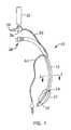
- FIG. 1is a depiction of an endotracheal tube embodiment of a multilumen catheter in accordance with the present disclosure
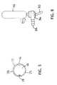
- FIG. 2is a depiction of a trach tube embodiment of a multilumen catheter in accordance with the present disclosure.
- FIG. 3is a cross-sectional view of the catheter of either FIG. 1 or 2 taken longitudinally through the catheter at 3 - 3 .
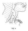
- FIG. 4is a drawing of a cuff for a tracheostomy tube as described in U.S. Pat. No. 6,612,305.
- FIG. 5is a drawing of a cuff for a tracheostomy tube as described in U.S. application 60/994,664.
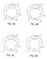
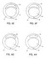
- FIG. 6A-Hshows various desirable shapes of suction lumens.
- FIG. 7depicts an elongated suction port on a cannula.
- FIG. 8depicts a rotational rinsing adaptor valve (rotational valve).
- FIG. 9depicts a push-type rinsing adaptor valve (push valve).
- FIG. 10depicts a straight rinsing adaptor valve (straight valve).
- FIGS. 11A and Bdepict a bellows-type rinsing adaptor valve (bellows valve).
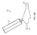
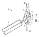
- FIGS. 12A and Bdepict a trigger activated rinsing adaptor valve (trigger valve).
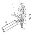
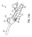
- FIGS. 13A and Bdepict an in-line pinching rinsing adaptor valve (pinch valve).
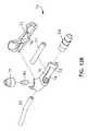
- FIG. 14depicts an in-line valve having a trigger tab that blocks flow.
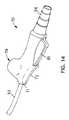
- FIG. 15depicts an in-line valve having a trigger bar that blocks flow.
- FIGS. 1 , 2 and 3a tracheal tube 10 in accordance with two embodiments of the present disclosure are depicted.
- FIG. 1depicts an endotracheal tube
- FIG. 2depicts a tracheostomy (trach) tube
- FIG. 3depicts a cross-section taken at 3 - 3 in either FIG. 1 or 2 .
- the tracheal tube 10 in the depicted embodimentsis a multilumen cannula 12 having at least one respiratory lumen 14 , at least one suction lumen 16 , and at least one inflation lumen 18 .
- each of these lumensis at least partially internal to the cannula 12 ( FIG. 3 ).
- the respiratory lumen 14is the largest lumen in the tube, extends through the entire cannula 12 and is adapted to mechanically ventilate a patient (not shown).
- the distal end 20 of the cannula 12is situated within the upper respiratory system of the patient.
- a balloon, bladder, or inflatable cuff 22is provided proximal to the distal end 20 .
- An inflation lumen 18terminates within the cuff 22 on the exterior surface 28 of the cannula 12 .
- the inflation lumen 18may be within the wall 25 of, or along the surface 28 of the cannula 12 until it is near the proximal end 38 of the tube 10 , at which point it becomes a separate tubing line 40 adapted to be used to supply an inflation fluid, generally air, to the cuff 22 .
- the cuff 22is shaped so that when it is inflated, it blocks the patient's trachea beneath the glottal area. This is known and understood by those skilled in the art to eliminate or at least to minimize the undesirable flow of fluids from the glottal and subglottal regions of the patient into the bronchus and lungs of the patient.
- the suction lumen 16is, similarly to the inflation lumen 18 , within the wall 25 or along the external surface 28 of the cannula 12 and terminates at a port 24 on the exterior surface 28 of the cannula 12 .
- the port 24 in the depicted embodimentis near an upper surface of the cuff 22 .
- the suction lumen 16is adapted to suction fluids that collect in the space above the cuff 22 in the patient's trachea (the subglottic area) without negatively impacting ventilation of the patient through the respiratory lumen 14 .
- the suction lumen 16extends proximally from the suction port 24 , along or within the wall 25 of the cannula 12 to a point where it separates from the cannula 12 and becomes a separate tubing line 30 .
- the tubing line 30is attached to a valve body 36 that is adapted to allow a user to provide suction to the suction lumen 16 from a source of suction (not shown) that is attached to the valve body 36 at a connector 34 .
- the valve body 36may also be used to provide a rinsing fluid contained within a bullet 32 or other appropriate container, to the suction lumen 16 . The functioning of the valve body 36 will be discussed in more detail below.
- the rinsing fluidmay be introduced into the suction lumen 16 from the bullet 32 while the suction is blocked off by the valve body 36 .
- the rinsing fluidtravels down (in a distal direction) the suction lumen 16 as far as is allowed by the condition of the lumen.
- the lumenis not completely occluded and allows rinsing fluid to exit at the suction port 24 above the cuff 22 in the trachea. Since the rinsing fluid is usually of a lower viscosity than typical secretions, it has the effect of lowering the viscosity of all of the liquid mix found in the space above the cuff 22 in the trachea once it is introduced.
- suctionmay be restored to the suction lumen 16 and the liquid and any secretions it may have loosened or dissolved may be removed, i.e. sucked out through the suction port 24 and suction lumen 16 .
- This proceduremay be repeated as deemed necessary. This procedure is performed at the discretion of the caregiver or user in order to clean secretions and other liquids that may collect and potentially clog the suction lumen 16 or suction port 24 . It is important to keep the suction lumen 16 open so that potentially deleterious secretions may be removed from the area above the cuff 22 .
- the rinsing fluidmay comprise water, saline, as well as other biocompatible liquids or mucolytic agents. Mucus may narrow or block the airways, making it difficult to breath. Mucolytic drugs are designed to modify the properties of the mucus to help loosen and clear the mucus from the airways by breaking up the sputum. Common mucolytic agents include erdosteine, acetylcysteine, bromheksin, carbocysteine and guiafenesin.
- the rinsing fluidmay also comprise air or combinations of air and liquids.
- a medicamentfor example, an antiseptic or an antibiotic, or a treatment such as a surfactant may be added to the rinsing fluid to obtain a desired effect on the patient, or to ease suctioning or cleaning of the suction lumen 16 .
- FIG. 3the cross sectional view of FIGS. 1 and 2 , one possible configuration of the tracheal tube 10 is depicted, more specifically a potential lumen arrangement is depicted within the cannula 12 .
- the suction lumen 16 and the inflation lumen 18are formed into the wall of the cannula 12 .
- This configurationis of course only meant to suggest one possible arrangement and other arrangements are included in the spirit and scope of the disclosure.
- the arrangement of lumens within the cannula 12is not limited in scope to any particular configuration.
- the layout of the lumens within the cannula 12may be altered for example or the suction and inflation lumens may be separate lumens not embedded within any one of the walls of the cannula 12 .
- a plurality of suction lumens 16may be provided. Each suction lumen would be configured essentially as described above, in that each would be rinsed by a rinsing fluid provided by a valve 36 .
- a single central valve 36may be provided to service all suction lumens 16 or a separate, dedicated valve 36 could be provided for each suction lumen 16 .
- Such an arrangementmay prove beneficial in more thorough rinsing of the suction lumen or lumens.
- a plurality of lumenswould allow for another lumen to be used should the previous lumen become clogged. Any of these embodiments are easily understood by one of skill in the art as they merely increase the number and arrangement of lumens provided. As such no specific drawings are needed for an understanding of these variations.
- the tracheal tube 10has a cuff 22 around its circumference on a lower (distal) portion of the tube that serves to block the normal air flow in the trachea so that assisted breathing takes place through the tracheal tube using a ventilator.
- the cuffis desirably made from a soft, pliable polymer such as polyethylene teraphathalate (PETP), low-density polyethylene (LDPE), polyvinyl chloride (PVC), polyurethane (PU) or polyolefin. It should be very thin; on the order of 25 microns or less, e.g. 20 microns, 15 microns, 10 microns or even as low as 5 microns in thickness.
- the cuffshould also desirably be a low pressure cuff operating at about 30 mmH 2 O or less, such as 25 mmH 2 O, 20 mmH 2 O, 15 mmH 2 O or less.
- a low pressure cuffoperating at about 30 mmH 2 O or less, such as 25 mmH 2 O, 20 mmH 2 O, 15 mmH 2 O or less.
- 6,802,317which describes a cuff for obturating a patient's trachea as hermetically as possible, comprising: a cuff which blocks the trachea below a patient's glottis, an air tube, the cuff being attached to the air tube and being sized to be larger than a tracheal diameter when in a fully inflated state and being made of a soft, flexible foil material that forms at least one draped fold in the cuff when inflated in the patient's trachea, wherein the foil has a wall thickness below or equal to 0.01 mm and the at least one draped fold has a loop found at a dead end of the at least one draped fold, that loop having a small diameter which inhibits a free flow of secretions through the loop of the at least one draped fold.
- the cuffmay be of a shape as described in U.S. patent application 60/994,664, now Ser. No. 12/206,517 or U.S. Pat. No. 6,612,305.
- the cuffexpands not only around the tube, as do the current models, but also cranially to it and to the stoma, sealing the stoma ( FIG. 4 ). This is achieved because the proximal point of attachment and the distal point of attachment of the inflatable cuff on the tube are not contiguous or, in other words, are at an angle ( ⁇ ) other than 180 degrees, relative to conventional devices.
- the cuffhas a distal cuff portion substantially centered about and attached to the distal end portion of the tube.
- the cuffalso has a proximal cuff portion attached to the bend region of the tube and positioned substantially off-center about the bend region below the proximal plane of the device.
- this configurationprovides for expansion of the cuff around the distal end portion of the tube and the proximal end portion of the tube below the proximal plane of the device to seal the trachea below the tracheal stoma and avoid sealing the trachea above the tracheal stoma ( FIG. 5 ).
- this configuration of the cuffwill allow secretions to exit the stoma.
- the tracheostomy tube devicemay have cuff walls that are non-uniform in thickness.
- the devicemay have a first portion of the cuff in which the walls have a thickness of about 20 to 30 micrometers and a second portion of the cuff in which the walls have a thickness of about 5 to about 15 micrometers.
- the first portion of the cuffis the portion of the cuff contacting the upper portion of a cross-sectional region of the tracheal lumen and the second portion of the second cuff is the portion of the cuff contacting the lower portion of the same cross-sectional region of the tracheal lumen.
- the inflatable cuff componentmay include a distal end, a distal attachment zone, a proximal end, a proximal attachment zone, an upper region and a lower region, wherein the upper region has a thickness of from about 15 to about 30 micrometers and the lower region has a thickness of from about 5 to about 15 micrometers.
- the cuff componentmay desirably be formed from thermoplastic polyurethane polymers, thermoplastic polyolefin elastomers, thermoplastic polyolefin block copolymers, SBS di-block elastomers, SEBS tri-block elastomers, polyvinyl chloride, polyethylene terephthalate and blends and mixtures thereof.
- the suction lumen 16 shown in FIG. 3may be round, oval or elliptical in shape in currently available commercial tracheal tubes.
- many different configurationswere tested. The tests showed that significant differences existed in the flow rate through the lumen, based simply on the shape chosen. It was found that the fluid that accumulated on the proximal side of the cuff was a complicated combination of secretions which were by no means newtonian. The viscosity of the fluid varied substantially, depending on the amount of shear the fluid was subjected to. As various shapes of lumens were investigated, it was found that shear varied within the lumen, with more shear at the bends or corners and less in the center, thus affecting the viscosity and impacting flow.
- FIG. 6A-Hare cross sectional views of a trach tube having a ventilating lumen 14 and a suction lumen 16 . More desirably, the bent oval shaped lumens of FIG. 6G , H performed better.
- the suction port opening 24 of FIGS. 1 and 2has been found to be susceptible to attaching itself to the back of the trachea and causing tissue damage. Continuous suctioning is more of a danger than intermittent suctioning but the potential for suction related tissue damage exists in either method.
- the suction port 24is conventionally placed on the cannula 12 in a position where it will be at the lowest point in the trachea above the cuff when the patient is laying on his back, and is conventionally a circular port. This area is where the secretions will naturally accumulate in the greatest amount. This is also an area of the cannula 12 that is subjected to high bending stress and so is more likely to allow the suction port 24 to come into contact with the trachea.
- FIG. 7depicts a suction port 24 on a cannula 12 above the cuff 22 where the suction port 24 is elongated circumferentially around the cannula 12 for some distance.
- This suction port 24connects to the suction lumen 16 and also has a shallow extension on either side that reduces the likelihood that the suction port 24 will attach itself to the tracheal wall.
- the shallow extensionsextend a short depth, e.g. a millimeter or two, into the outer surface 28 of the cannula 12 but do not go all the way through the cannula 12 except in the area where the suction port 24 communicates with the suction lumen 16 .
- the elongated suction port 24thus reduces damage to the trachea and helps maintain the suction line open by preventing the cannula 12 from being sucked against the tracheal wall.
- the elongated suction port 24may be two to five times wider than the conventional circular port, desirably about three times as wide.
- the valveis an important part of the tracheal tube and system of suctioning secretions disclosed herein.
- the valveis used to suction and rinse the tubing line 30 and by extension the suction lumen 16 , suction port 24 and the space in the trachea above the cuff 22 . It is desired that the valve have the capability of easily and repeatedly alternately suctioning and providing rinsing fluid through the suction lumen, i.e., the user may “pulse” the line to loosen, break up and remove secretions and deposits that may partially or completely block or clog the suction lumen.
- valveautomatically (i.e., by itself, without intervention by a user) return to a normal, default or “fail-safe” position in which suction is applied to the system so that secretions are removed, after the user has finished using the valve. If the valve remains in the “rinse” position once the bullet providing rinsing fluid is empty, secretions will build up in the space above the cuff 22 and the purpose for having a suctioning line will be defeated. It is also important that the valve close the access to the suction line prior to opening access to the rinsing fluid bullet, otherwise the fluid will be sucked out of the bullet to the source of suction and wasted.
- valverequire a positive action on the part of the user to move it to the rinse position, so that the inadvertent movement of the patient will not activate the valve. Should the patient roll over onto the valve, for example, the valve should remain in the position the caregiver desires, generally the fail-safe or suction position, or should move back to the fail-safe position by itself relatively quickly when the force exerted by the patient is removed. Lastly, it is desired that rinsing and suctioning be capable of being performed and the system kept closed. Removing the bullet, for example, each time suctioning was applied, would repeatedly open the system and allow for the entry of germs.
- the valve 36may be as depicted in FIG. 8 .
- This Figuredepicts a rotational rinsing adaptor valve (rotational valve) that accommodates a sterile rinsing fluid (e.g. saline) bullet 32 or syringe.
- the valve 36may be connected to a vacuum source by a connector 34 and to the suction lumen (not shown) by a tubing line 30 .
- the normal or fail-safe position of the valveis to allow constant suction to the tubing line 30 .
- a bullet 32is inserted and is rotated as indicated by the arrow.
- This rotational movement of the bullet 32turns a three way valve, blocking the source of suction or vacuum and opening up fluid access from the bullet 32 to the tubing line 30 .
- the tubing line 30is in fluid communication with the suction lumen 16 .
- the bullet 32may be squeezed to force the rinsing fluid into the tubing line 30 . Once the user has finished instilling rinsing fluid into the lumen, releasing the bullet 32 allows a spring or other automatic means (not shown) to rotate the bullet 32 in the opposite direction, back to its original (normal) position, closing the fluid access from the bullet 32 and re-opening the flow path to the source of vacuum.
- Re-establishing the fluid communication between the source of vacuum and the tubing line 30results in suctioning of the suction lumen and the space above the cuff 22 through the suction port 24 .
- the usermay repeatedly alternate between suction and rinsing fluid as desired, thus pulsing the system to loosen and remove secretions.
- valve 36may be as depicted in FIG. 9 .
- This Figuredepicts a push-type rinsing adaptor valve (push valve) that accommodates a sterile rinsing fluid bullet 32 or syringe.
- the valve 36may be connected to a vacuum source by a connector 34 and to the suction lumen (not shown) by a tubing line 30 .
- the normal or fail-safe position of the valveis to allow constant suction to the tubing line 30 .
- a bullet 32 containing a rinsing fluidis inserted into the valve 36 as shown.
- the bullet 32When the bullet 32 is pushed downward toward the valve 36 the bullet 32 blocks the source of vacuum and opens access from the bullet 32 to the tubing line 30 that is in fluid communication with the suction lumen.
- the bullet 32may be squeezed to force the rinsing fluid into the tubing line 30 .
- releasing the bullet 32allows a spring or other automatic means (not shown) to move the bullet 32 in the opposite direction, back to its original (normal) position, closing the fluid access from the bullet 32 and re-opening the flow path to the source of vacuum.
- the usermay repeatedly alternate between suction and rinsing fluid as desired, thus pulsing the system to loosen and remove secretions.
- the valve 36may be as depicted in FIG. 10 .
- This Figuredepicts a straight rinsing adaptor valve (straight valve) that accommodates a sterile rinsing fluid bullet 32 or syringe.
- the valve 36may be connected to a vacuum source by a connector 34 and to the suction lumen (not shown) by a tubing line 30 .
- the normal or fail-safe position of the valveis to allow constant suction to the tubing line 30 .
- a bullet 32 containing a rinsing fluidis inserted.
- the bullet 32When the bullet 32 is pushed downward, it blocks the flow path from the suction source to the tubing line 30 and establishes a fluid connection between the bullet 32 and the tubing line 30 .
- the bullet 32may be squeezed to force the rinsing fluid into the tubing line 30 .
- releasing the bullet 32allows a spring or other automatic means (not shown) to move the bullet 32 in the opposite direction, back to its original (normal) position, closing the fluid access from the bullet 32 and re-opening the flow path to the source of vacuum.
- the usermay repeatedly alternate between suction and rinsing fluid as desired, thus pulsing the system to loosen and remove secretions.
- FIGS. 11A and 11Bdepict a bellows activated suction valve where the cross sectional view is that of FIG. 11B .
- the connector 34is connected to a source of suction (not shown).
- Suctioned fluid or aircan travel through the tubing line 30 from the patient end 42 , through the center lumen 51 of the piston 46 , and then pass through an orifice 47 into the annular space 45 in which is found the spring 44 .
- the suctioned fluid or airmay pass around the perpendicular section 52 of the pin 48 and out to the source of suction beyond the connector 34 .
- the pin 48does not block fluid or air flow but only serves to center and hold in place the other components.
- the fluid (one-way) check valve 49opens and rinsing fluid flows from the bullet 32 into the bellows 41 .
- the orifice 47restores suction to the bellows 41 .
- Such a course of actionwould of course result in the rinsing fluid being sucked out of the bellows 41 toward the source of suction, and would be unproductive. Rather than relax the squeezing of the bellows 41 completely, however, the squeezing of the bellows 41 may be only partially relaxed, allowing rinsing fluid to fill the bellows 41 but not opening the orifice 47 .
- Squeezing of the bellows 41may be reinitiated, resulting in the closing of the fluid check valve 49 and the rinsing fluid being forced out of the bellows 41 , through the rinse check valve 50 and into the tubing line 30 toward the patient.
- the caregivermay pulse rinsing fluid into the tubing line 30 and on to the suction port 24 for delivery to the space in the trachea above the cuff 22 .
- This alternating of rinsing fluid and suctionmay provide a more effective method of removing deposits and secretions than steady state suctioning.
- the valve 40may also include a tethered cap 53 that may be used to protect the saline check valve 49 and the rest of the valve 40 from contamination when the bullet 32 is not in place.
- FIGS. 12A and 12Bdepict a trigger activated suction valve 60 where the cross sectional view is that of FIG. 12B .
- Squeezing the trigger 61moves a pivot valve 62 into the closed position, squeezing closed the tubing line 30 within the valve 60 and blocking the source of suction.
- There are two one-way check valves in the stationary piston 65a suction lumen check valve and a rinsing fluid check valve.
- the triggerAs the trigger continues to move inwards as it is squeezed, it compresses the spring 62 , and forces the rinsing fluid in the trigger space 63 through a suction lumen check valve 65 , through a narrow tube 66 and into the tubing line 30 at the point 67 where the narrow tube 66 connects to the main tubing line 30 .
- Releasing the trigger 61allows the spring 62 to push the trigger 61 outward, opening the rinsing fluid check valve and allowing rinsing fluid to flow from the bullet 32 , through tubing (not visible) and into the trigger space 63 .
- the pivot valve 62remains closed until the trigger 61 is entirely released, allowing the user to send repeating pulses of rinsing fluid through the tubing line 30 to the suction port 24 .
- the usermay alternatively pulse rinsing fluid into the tubing line 30 and restore suction to the tubing line 30 .
- the springautomatically opens access from the source of suction to the suction lumen and closes access from the bullet to the suction lumen.
- the triggermay be positioned on an upper surface of the valve 60 or on a side, as desired, and still be within the teachings and inventive spirit of the active trigger valve presented herein.
- FIG. 13A and its exploded view 13 Bdepict an in-line pinching rinse valve 70 .
- This relatively less complicated valvehas a body 71 that, in this embodiment, is made from two mirror image halves; a right half 72 and a left half 73 where the forward portion of the valve is defined as the patient facing end that connects to the tubing line 30 .
- the bodymay alternatively be made from a top and bottom half or may be made as a single piece.
- the rear portion of the valve 70is a connector 34 for the source of suction (not shown).
- At least one of the body halveshas a peninsular tab 74 (only visible on the left half 73 in the Figures) that is separated from its body half by a slight gap 75 for much of its length.
- the peninsular tab 74remains attached to its body half at one end.
- the gap 75allows the peninsular tab 74 to flex and move relative to the body half without breaking, provided the material from which the body half is made is sufficiently thin and or flexible, and to spring back to its original position upon release of the squeezing force.
- a ridge 76desirably placed perpendicularly to the crimp tubing 77 , that is sized so that when the peninsular tab 74 is squeezed by a user's fingers, the ridge 76 will contact an internal length of crimp tubing 77 and, if sufficient force is applied, close the lumen of the crimp tubing 77 and block the communication of the source of suction through the crimp tubing 77 .
- the exact size and shape of the peninsular tab 74 and the ridge 76may be varied according to the desire of the valve designer and remain within the teachings of this disclosure, provided the lumen of the crimp tubing 77 may be closed by squeezing the peninsular tab(s) 74 .
- the ridge 76may, instead of being a rectangular feature as shown in the Figure, be another shape like a round or oval bump that is placed in a position to come into contact with the crimp tubing 77 when the peninsular tab(s) 74 are squeezed together. It is also possible to design the peninsular tab(s) 74 in a way such that the ridge 76 is deleted entirely from the body halves and the peninsular tab(s) 74 directly impinge upon the crimp tubing 77 and close its lumen.
- the patient facing end of the crimp tubing 77is in fluid communication with the tubing line 30 that in turn communicates with the suction lumen 16 and suction port 24 , discussed previously.
- the other end of the crimp tubing 77is in fluid communication with the connector 34 that further communicates with the source of suction.
- the valve 70has an inlet 78 to receive rinsing fluid from a bullet.
- the valve 70desirably has an adapter 79 that is designed to accept the bullet and fit snugly against it to reduce fluid leakage, and a check valve 80 through which the saline solution will flow from the bullet.
- the check valve 80requires more force to open it than is exerted by the source of suction alone, thus requiring the user to squeeze the bullet to provide sufficient force to open the check valve 80 and move rinsing fluid into the tubing line 30 .
- An optional tethered cap(not shown) adapted to cover the inlet 78 when a bullet is not in place may be provided.
- a usermay simply squeeze the peninsular tab(s) 74 on the body 71 with one hand to close the lumen of the crimp tubing 77 and block the source of suction from the tubing line 30 , and, keeping the crimp tubing 77 closed, squeeze the fluid bullet with the other hand to force liquid into the tubing line 30 and on toward the space above the cuff 22 in the trachea. It has been found that users generally prefer to perform one function with each hand, and that requiring more than one function to be performed with one hand can cause confusion. It is advantageous, therefore, that this valve has one function for each hand.
- the usermay stop squeezing the bullet and relax pressure on the peninsular tab(s) 74 . This permits the peninsular tab(s) 74 to spring back to the original position, allowing the crimp tubing 77 to resume its normal shape and restoring suction to the tubing line 30 .
- the usermay repeatedly alternate between suction and rinsing fluid as desired, thus pulsing the system to loosen and remove secretions, without removing the bullet.
- the tubing line 30may be slid into the interior of the body 71 and mated with the connector 34 , thus dispensing with a separate piece acting as the crimp tubing 77 .
- the tubing line 30may be punctured for access by the source of rinsing fluid.
- the body 71may be wrapped with a polymeric material like a “shrink wrap” plastic that shrinks in place in response to heat, for example, to cover over the gap 75 and prevent glove entrapment in the gap 75 .
- the peninsular tab(s) 74may have surface topography 80 like lines, chevrons, dimples, reverse dimples and the like, in order to improve the tactile sensation felt by a user wearing gloves and to improve the quality of the user's grip on the body 71 .
- the valve 70 of FIG. 13Amay have body halves that are between 3 and 10 cm in length, desirably about 7 cm in length and between 0.5 and 2 cm in diameter, desirably about 1.7 cm.
- Two peninsular tabs 74 located opposite each othermay be between 1 and 5 cm in length, desirably about 2.5 cm and a ridge 76 may be located approximately in the lengthwise center of each peninsular tab 74 .
- the gap 75may be between 0.3 and 3 mm in width, desirably about 1 mm.
- FIG. 14shows another embodiment that, like the valve of FIG. 13 , allows for one handed operation of the valve.
- This valve 70is similar in many ways to the valve of FIG. 13 but differs in the method of activation.
- depressing a trigger tab 81 on the bottom of the valve 70results in crimping the tubing inside the body and closing it.
- Releasing the trigger tab 81allows the crimp tubing (not shown) to re-open and re-establishes communication between the source of suction and the suction lumen.
- FIG. 15shows another embodiment that, like the valve of FIG. 13 , allows for one handed operation of the valve.
- This valve 70is similar in many ways to the valve of FIG. 13 but differs in the method of activation.
- moving a trigger bar 82 on the bottom of the valve 70 rearwardresults in crimping the tubing inside the body and closing it.
- Releasing the trigger bar 82allows the crimp tubing (not shown) to re-open and re-establishes communication between the source of suction and the suction lumen.
- the materials of construction of the valves disclosed hereinmay be, for the bodies, polyolefins like polyethylene and polypropylene, nylons, polycarbonates, acrylonitrile butadiene styrene (ABS), acrylics, PVC and the like. Particularly suitable is high density polyethylene (HDPE).
- Materials of construction of the flexible parts like the check valves and tubinginclude silicones, polyurethanes, polyethylene terephthalate (PET), low-density polyethylene (LDPE), polyvinyl chloride (PVC), or elastomeric-based polyolefins.
- a medical care providerwould insert the tracheal tube 10 into the patient's trachea in a manner known and understood by those of skill in the art; through oral or nasal intubation or through a tracheostomy.
- the inflatable cuff 22would be inflated by air supplied through the inflation lumen 18 so as to sealingly engage the walls of the patient's trachea. This would effectively prevent or at least minimize flow of undesirable fluids from the subglottic space into the bronchus and lungs. Ventilation of the patient through the respiratory lumen 14 may occur at this time and continue for as long as necessary.
- the subglottic space within the patient's tracheamay be suctioned through the suction lumen 16 via the port 24 through the wall 25 of the cannula 12 . Such suctioning may be performed continuously or intermittently as desired. Also at the discretion of the caregiver, the suction lumen 16 and/or the space above the cuff 22 may be rinsed and suctioned. This is accomplished by blocking the source of suction from the suction lumen 16 through the use of the valve 36 and introducing a rinsing fluid from a bullet 32 to the suction lumen 16 as described in more detail above.
- the valve 36is re-opened to the source of vacuum and suction restored, thus evacuating the suction lumen 16 and removing any secretions and other liquids in the suction lumen 16 and, desirably, any secretions accumulated above the cuff 22 .
- a treatmentmay be added to the rinsing fluid such as a medicament, for example, an antiseptic, antibiotic or mucolytic agent. In that case, it may be desirable to allow more time between the introduction of the rinsing fluid and the evacuation of the rinsing fluid from the lumen and cuff area so as to gain the desired therapeutic effect prior to suctioning.
Landscapes
- Health & Medical Sciences (AREA)
- Pulmonology (AREA)
- Heart & Thoracic Surgery (AREA)
- Life Sciences & Earth Sciences (AREA)
- General Health & Medical Sciences (AREA)
- Anesthesiology (AREA)
- Biomedical Technology (AREA)
- Hematology (AREA)
- Veterinary Medicine (AREA)
- Animal Behavior & Ethology (AREA)
- Engineering & Computer Science (AREA)
- Public Health (AREA)
- Emergency Medicine (AREA)
- Vascular Medicine (AREA)
- Oral & Maxillofacial Surgery (AREA)
- Surgery (AREA)
- External Artificial Organs (AREA)
- Surgical Instruments (AREA)
Abstract
Description
Claims (4)
Priority Applications (16)
| Application Number | Priority Date | Filing Date | Title |
|---|---|---|---|
| US12/533,531US9119926B2 (en) | 2009-07-31 | 2009-07-31 | Subglottic suctioning system |
| AU2010277235AAU2010277235B2 (en) | 2009-07-31 | 2010-06-25 | Subglottic suctioning system |
| CA2766971ACA2766971C (en) | 2009-07-31 | 2010-06-25 | Subglottic suctioning system |
| ES10742884.9TES2564986T3 (en) | 2009-07-31 | 2010-06-25 | Subglottic Suction System |
| EP16154798.9AEP3056237B1 (en) | 2009-07-31 | 2010-06-25 | Subglottic suctioning system |
| CN201080034057.3ACN102470228B (en) | 2009-07-31 | 2010-06-25 | subglottic suction system |
| MX2012001137AMX339647B (en) | 2009-07-31 | 2010-06-25 | Subglottic suctioning system. |
| JP2012522280AJP5683586B2 (en) | 2009-07-31 | 2010-06-25 | Subglottic suction system |
| KR1020177001782AKR101808053B1 (en) | 2009-07-31 | 2010-06-25 | Subglottic suctioning system |
| PCT/IB2010/052927WO2011013015A1 (en) | 2009-07-31 | 2010-06-25 | Subglottic suctioning system |
| RU2012107127/14ARU2537944C2 (en) | 2009-07-31 | 2010-06-25 | Aspiration system subjacent glottal aperture |
| BR112012001018ABR112012001018A2 (en) | 2009-07-31 | 2010-06-25 | subglottic suction system |
| CN201510765197.2ACN105288811B (en) | 2009-07-31 | 2010-06-25 | Subglottic suctioning system |
| KR1020127002065AKR101702451B1 (en) | 2009-07-31 | 2010-06-25 | Subglottic suctioning system |
| EP10742884.9AEP2459263B1 (en) | 2009-07-31 | 2010-06-25 | Subglottic suctioning system |
| US14/804,812US10245401B2 (en) | 2009-07-31 | 2015-07-21 | Subglottic suctioning system |
Applications Claiming Priority (1)
| Application Number | Priority Date | Filing Date | Title |
|---|---|---|---|
| US12/533,531US9119926B2 (en) | 2009-07-31 | 2009-07-31 | Subglottic suctioning system |
Related Child Applications (1)
| Application Number | Title | Priority Date | Filing Date |
|---|---|---|---|
| US14/804,812ContinuationUS10245401B2 (en) | 2009-07-31 | 2015-07-21 | Subglottic suctioning system |
Publications (2)
| Publication Number | Publication Date |
|---|---|
| US20110023884A1 US20110023884A1 (en) | 2011-02-03 |
| US9119926B2true US9119926B2 (en) | 2015-09-01 |
Family
ID=42735275
Family Applications (2)
| Application Number | Title | Priority Date | Filing Date |
|---|---|---|---|
| US12/533,531Active2032-01-06US9119926B2 (en) | 2009-07-31 | 2009-07-31 | Subglottic suctioning system |
| US14/804,812Active2032-01-25US10245401B2 (en) | 2009-07-31 | 2015-07-21 | Subglottic suctioning system |
Family Applications After (1)
| Application Number | Title | Priority Date | Filing Date |
|---|---|---|---|
| US14/804,812Active2032-01-25US10245401B2 (en) | 2009-07-31 | 2015-07-21 | Subglottic suctioning system |
Country Status (12)
| Country | Link |
|---|---|
| US (2) | US9119926B2 (en) |
| EP (2) | EP2459263B1 (en) |
| JP (1) | JP5683586B2 (en) |
| KR (2) | KR101808053B1 (en) |
| CN (2) | CN102470228B (en) |
| AU (1) | AU2010277235B2 (en) |
| BR (1) | BR112012001018A2 (en) |
| CA (1) | CA2766971C (en) |
| ES (1) | ES2564986T3 (en) |
| MX (1) | MX339647B (en) |
| RU (1) | RU2537944C2 (en) |
| WO (1) | WO2011013015A1 (en) |
Cited By (12)
| Publication number | Priority date | Publication date | Assignee | Title |
|---|---|---|---|---|
| US20150335842A1 (en)* | 2009-07-31 | 2015-11-26 | Avent, Inc. | Subglottic suctioning system |
| US10143814B2 (en) | 2011-03-29 | 2018-12-04 | Teleflex Life Sciences Unlimited Company | Fluid input module for multi-lumen catheters |
| US10322253B2 (en) | 2011-03-29 | 2019-06-18 | Teleflex Life Sciences Unlimited Company | Ballooned ventilation tube cleaning device |
| US10500360B1 (en) | 2014-08-29 | 2019-12-10 | Teleflex Life Sciences Unlimited Company | Catheter for cleaning of tracheal ventilation tubes |
| US10926009B2 (en) | 2016-01-06 | 2021-02-23 | Teleflex Life Sciences Pte. Ltd. | Closed suction system |
| US10946153B2 (en) | 2016-05-16 | 2021-03-16 | Teleflex Life Sciences Pte. Ltd. | Mechanical user control elements for fluid input module |
| US11324526B2 (en) | 2018-02-02 | 2022-05-10 | Calyxo, Inc. | Devices and methods for minimally invasive kidney stone removal by combined aspiration and irrigation |
| US11452831B2 (en) | 2016-01-06 | 2022-09-27 | Airway Medix S.A. | Closed suction system |
| USD1024310S1 (en) | 2019-03-28 | 2024-04-23 | Bateman Bottle, Llc | Implant removal device |
| US11980394B2 (en) | 2017-06-05 | 2024-05-14 | Bateman Bottle, Llc | Device for removal of implants and associated method of use |
| US12256989B2 (en) | 2022-09-29 | 2025-03-25 | Calyxo, Inc. | Tool guiding device for kidney stone treatment apparatus |
| US12329399B2 (en) | 2022-03-02 | 2025-06-17 | Calyxo, Inc. | Kidney stone treatment system |
Families Citing this family (37)
| Publication number | Priority date | Publication date | Assignee | Title |
|---|---|---|---|---|
| WO2011022497A1 (en)* | 2009-08-20 | 2011-02-24 | C. R. Bard, Inc. | Ventilator attachment fitting usable on a endotracheal tube having an integrally formed suction lumen and method of making and/or using the same |
| US9358328B2 (en) | 2009-12-15 | 2016-06-07 | Prabhat K. Ahluwalia | Suction device |
| EP2588180B1 (en) | 2010-06-29 | 2016-12-07 | Hospitech Respiration Ltd. | Device and method for irrigating-evacuating a body cavity |
| CN102631737A (en)* | 2011-07-22 | 2012-08-15 | 湛江市事达实业有限公司 | Sputum-suction and medicament-injection trachea cannula, trachea cannula assembly and manufacturing method of trachea cannula |
| CN102631740A (en)* | 2011-07-22 | 2012-08-15 | 湛江市事达实业有限公司 | Sputum-suction trachea cannula, trachea cannula assembly and manufacturing method of trachea cannula |
| US9242058B2 (en)* | 2011-07-29 | 2016-01-26 | Covidien Lp | Tracheal tube positioning devices and methods |
| US8776796B2 (en)* | 2011-12-09 | 2014-07-15 | Colabs, Inc. | Apparatus and method for improved assisted ventilation |
| US9352112B2 (en)* | 2011-12-13 | 2016-05-31 | Covidien Lp | Shaped evacuation port for a multi-lumen tracheal tube |
| EP2800599B1 (en) | 2012-01-03 | 2017-05-31 | Hospitech Respiration Ltd. | System for controlling and monitoring flow in an endotracheal tube |
| US8945093B2 (en) | 2012-03-20 | 2015-02-03 | Minimally Invasive Surgical Technologies, Inc. | Suction device |
| US9744276B2 (en) | 2012-03-20 | 2017-08-29 | Prabhat Kumar Ahluwalia | Suction device |
| CN102727979B (en)* | 2012-06-26 | 2016-08-03 | 丁宝纯 | A kind of Double-layer cuff trachea cannula |
| CN103751895A (en)* | 2013-01-25 | 2014-04-30 | 郦文泽 | Porous suction tracheal intubation tube |
| US9579475B2 (en) | 2013-10-10 | 2017-02-28 | NevAp, Inc. | Tracheal tube |
| US9327091B2 (en) | 2013-10-10 | 2016-05-03 | Nev Ap, Inc. | Tracheal tube and suction device |
| US9446213B2 (en) | 2013-10-10 | 2016-09-20 | NevAp, Inc. | Tracheal tube |
| KR101455087B1 (en)* | 2014-02-28 | 2014-10-27 | 강정길 | Portable suction pump with cathether reel of artificial intelligence type |
| DE102014109001A1 (en) | 2014-06-26 | 2015-12-31 | Tracoe Medical Gmbh | tracheal |
| CN107072760B (en) | 2014-08-14 | 2018-09-14 | Coeo实验室私营有限公司 | Automatically removes fluid from multiple areas of the airway |
| DE102015201094B4 (en) | 2015-01-22 | 2018-08-23 | Asskea Gmbh | Device for aspirating a body fluid |
| US10149956B2 (en) | 2015-02-28 | 2018-12-11 | John P. Ure | Bi-lateral endobronchial suctioning device and medical suctioning system for intubated patients |
| KR101723969B1 (en)* | 2016-03-29 | 2017-04-06 | (주)엘메카 | Catheter Guide Structure |
| EP3468478B1 (en)* | 2016-06-09 | 2025-02-12 | C. R. Bard, Inc. | Systems for correcting and preventing occlusion in a catheter |
| KR101877533B1 (en)* | 2016-06-21 | 2018-07-11 | (주)엘메카 | Tube Structure Installed in Bronchus for Sputum Removing |
| EP3525859A4 (en) | 2016-10-12 | 2020-06-10 | Nevap, Inc. | SUCTION DEVICES FOR MEDICAL DEVICES AND MEDICAL DEVICE SYSTEMS INCLUDING SUCTION DEVICES |
| CN110494680B (en)* | 2017-04-11 | 2022-06-03 | 乌多·塔勒 | Equipment for sealing and evacuating containers with viscous liquids |
| JP6924890B2 (en)* | 2017-07-05 | 2021-08-25 | テレフレックス ライフ サイエンシーズ アンリミテッド カンパニー | Mechanical user control elements for fluid input modules |
| US10636324B2 (en)* | 2017-12-21 | 2020-04-28 | Laerdal Medical As | Device for training tracheal suctioning |
| CN108721748B (en)* | 2018-01-03 | 2021-04-23 | 华中科技大学同济医学院附属同济医院 | Endotracheal tube for reconstruction of peak cough flow |
| US12097325B2 (en) | 2018-11-15 | 2024-09-24 | NevAp, Inc. | Systems and devices for preventing occlusion of a suction line resident in a medical device |
| EP4034208B1 (en)* | 2019-09-24 | 2025-08-13 | Advanced Medical Balloons GmbH | Flow-optimised supply to a balloon element that seals dynamically and in sync with organs |
| KR102358496B1 (en)* | 2020-01-23 | 2022-02-03 | 울산대학교 산학협력단 | Multi-channel suction and irrigation tube |
| US20220023512A1 (en)* | 2020-07-21 | 2022-01-27 | Carl Morgan | Exhalation Disposal System |
| CN111939413A (en)* | 2020-08-21 | 2020-11-17 | 道琪康医学科技(苏州)有限公司 | Multifunctional airway management system |
| US11786683B2 (en) | 2020-12-11 | 2023-10-17 | Blake J. Hyde | Irrigating intraluminal suction inner cannula system |
| CN115364324B (en)* | 2022-10-25 | 2023-01-13 | 卫圣康医学科技(江苏)有限公司 | Air flue management control system |
| CN118303943B (en)* | 2024-03-14 | 2024-12-17 | 上海交通大学医学院附属瑞金医院 | Airway management tool and manufacturing method thereof |
Citations (58)
| Publication number | Priority date | Publication date | Assignee | Title |
|---|---|---|---|---|
| US4240417A (en) | 1979-06-13 | 1980-12-23 | Holever Bernard K | Tracheal tube adapter for ventilating apparatus |
| US4305392A (en) | 1978-09-29 | 1981-12-15 | Chester Martin H | Endotracheal tube with suction device |
| US4584998A (en) | 1981-09-11 | 1986-04-29 | Mallinckrodt, Inc. | Multi-purpose tracheal tube |
| US4680026A (en)* | 1982-03-29 | 1987-07-14 | Weightman Barry O | Suction-irrigation equipment having a reciprocating valve |
| US4696669A (en) | 1986-03-24 | 1987-09-29 | Menhusen Monty J | Hand held combination flush with adjustable nozzle and/or suction apparatus |
| US5083561A (en) | 1990-06-14 | 1992-01-28 | Russo Ronald D | Tracheal suction catheter |
| US5139018A (en) | 1990-07-24 | 1992-08-18 | Superior Healthcare Group, Inc. | Patient ventilating apparatus with aspirating catheter |
| US5146916A (en) | 1990-01-05 | 1992-09-15 | Catalani Angelo S | Endotracheal tube incorporating a drug-irrigation device |
| US5174283A (en) | 1989-11-08 | 1992-12-29 | Parker Jeffrey D | Blind orolaryngeal and oroesophageal guiding and aiming device |
| US5193544A (en) | 1991-01-31 | 1993-03-16 | Board Of Trustees Of The Leland Stanford Junior University | System for conveying gases from and to a subject's trachea and for measuring physiological parameters in vivo |
| US5201310A (en) | 1990-12-05 | 1993-04-13 | Smiths Industries Public Limited Company | Medico-surgical tube with sealing cuff and a suction lumen at the top of the cuff |
| US5207641A (en) | 1989-05-15 | 1993-05-04 | Bird Medical International Inc. | Medical rotary valve having aspiration, insufflation and an intermediate flushing positions |
| US5279549A (en)* | 1991-01-04 | 1994-01-18 | Sherwood Medical Company | Closed ventilation and suction catheter system |
| US5285778A (en) | 1991-04-19 | 1994-02-15 | Mackin Robert A | Endotracheal tube wih fibers optic illumination and viewing and auxiliary tube |
| US5290263A (en)* | 1989-02-02 | 1994-03-01 | Regents Of The University Of Minnesota | Bidirectional check valve catheter |
| US5354267A (en)* | 1993-09-20 | 1994-10-11 | Vital Signs Inc. | Irrigation and suction apparatus |
| US5513627A (en) | 1995-01-27 | 1996-05-07 | Flam; Gary H. | Esophageal tracheal intubator airway |
| USRE35531E (en) | 1995-01-26 | 1997-06-17 | The Laryngeal Mask Company Ltd. | Laryngeal mask assembly and method for removing same |
| US5735271A (en) | 1994-05-18 | 1998-04-07 | Ballard Medical Products | Multiple access adaptors for monitoring, sampling, medicating, aspirating, and ventilating the respiratory tract of a patient |
| US5738648A (en) | 1996-01-23 | 1998-04-14 | Valleylab Inc | Method and apparatus for a valve and irrigator |
| US5832920A (en) | 1995-10-04 | 1998-11-10 | Smiths Industries Public Limited Co. | Tracheal tube with integral suction lumen |
| US5845634A (en) | 1997-03-18 | 1998-12-08 | Parker Medical Limited Partnership | Endoscope viewing system with orotracheal introducing guide |
| WO1999038548A2 (en) | 1998-01-28 | 1999-08-05 | Jaime Vargas | Oral pharyngeal evacuation endotracheal tube |
| US5976072A (en) | 1998-01-29 | 1999-11-02 | Johns Hopkins University | Copa method for fiberoptic endotracheal intubation |
| US6116243A (en) | 1997-03-18 | 2000-09-12 | Smiths Industries Public Limited Company | Laryngeal mask assemblies |
| US6119695A (en) | 1998-11-25 | 2000-09-19 | Augustine Medical, Inc. | Airway device with provision for lateral alignment, depth positioning, and retention in an airway |
| US6152136A (en) | 1997-05-22 | 2000-11-28 | Smiths Industries Public Limited Company | Cuffed tube assemblies |
| US20010001059A1 (en)* | 1998-04-28 | 2001-05-10 | The Regents Of The University Of California. | Method and kit for obtaining fluids and cellular material from breast ducts |
| US6261401B1 (en) | 1998-05-09 | 2001-07-17 | Smiths Group Plc | Laryngeal masks and manufacture |
| US20010023312A1 (en) | 1997-12-01 | 2001-09-20 | Pacey John A. | Intubation instrument |
| US20010044600A1 (en) | 2000-05-17 | 2001-11-22 | Elkins John I. | Closed catheter suction system |
| US6427686B2 (en) | 1996-10-16 | 2002-08-06 | Augustine Medical, Inc. | Airway device with provision for coupling to an introducer |
| JP2003093511A (en) | 2001-09-25 | 2003-04-02 | Nippon Sherwood Medical Industries Ltd | Tracheostomy tube |
| US6546931B2 (en) | 2000-12-13 | 2003-04-15 | Future Top Medical Environment Technic, Co., Ltd. | Supraglottic airway structure specifically used for anesthesia |
| US6668821B2 (en) | 1996-02-26 | 2003-12-30 | Evergreen Medical Incorporated | Laryngeal mask airway |
| US6668832B2 (en) | 2001-12-28 | 2003-12-30 | The Regents Of The University Of California | Endotracheal tube |
| US20040007236A1 (en) | 2002-03-15 | 2004-01-15 | Mcgee Thomas E. | Endotracheal surfactant distribution system |
| US6705321B2 (en) | 1997-04-10 | 2004-03-16 | Daniel J. Cook | Laryngeal mask adapter |
| JP2004283329A (en) | 2003-03-20 | 2004-10-14 | Tokunaga Soki Kenkyusho:Kk | Artificial respiration system and tracheal cannula |
| US20050197645A1 (en) | 2004-03-04 | 2005-09-08 | John Karpowicz | Apparatus for vacuum-assisted irrigation and drainage of a body cavity |
| US6978783B2 (en) | 2000-04-06 | 2005-12-27 | Unomedical A/S | Manifold |
| US20050284483A1 (en)* | 2004-06-24 | 2005-12-29 | Vinu Patel | Endotracheal tube with integral heart, lung, and temperature monitor |
| US7004169B2 (en) | 1999-10-07 | 2006-02-28 | Indian Ocean Medical Inc. | Laryngeal mask with large-bore gastric drainage |
| US7025755B2 (en)* | 1997-04-14 | 2006-04-11 | Baxter International Inc. | Medical suctioning apparatus and methods of use |
| US7040322B2 (en) | 2001-11-08 | 2006-05-09 | Fortuna Anibal De Oliveira | Combination artificial airway device and esophageal obturator |
| US20060162730A1 (en) | 2005-01-26 | 2006-07-27 | Raymond Glassenberg | Video-assisted laryngeal mask airway devices |
| US20070044807A1 (en)* | 2005-08-25 | 2007-03-01 | Kimberly-Clark Worldwide, Inc. | Multilumen tracheal catheter with rinse lumen |
| US20070089748A1 (en)* | 2005-10-26 | 2007-04-26 | Madsen Edward B | Tracheal catheter with closeable suction lumen |
| US20070199460A1 (en) | 2006-02-21 | 2007-08-30 | Cyman Theodore F Jr | Systems and methods for high speed variable printing |
| WO2008023147A1 (en) | 2006-08-23 | 2008-02-28 | Smiths Group Plc | Fluid-flow connectors and arrangements |
| US20080053454A1 (en) | 2006-09-01 | 2008-03-06 | Nellcor Puritan Bennett Incorporated | Endotracheal tube including a partially inverted cuff collar |
| CN201048980Y (en) | 2007-06-11 | 2008-04-23 | 汪忠镐 | Anti-reflux type radio-frequency therapeutic tube |
| US20080121236A1 (en)* | 2006-11-25 | 2008-05-29 | Smiths Group Plc | Suction apparatus and connectors |
| US7469700B2 (en)* | 1994-06-17 | 2008-12-30 | Trudell Medical Limited | Nebulizing catheter system for delivering an aerosol to a patient |
| US20090038620A1 (en)* | 2005-12-05 | 2009-02-12 | Shai Efrati | Endotracheal Tube and Intubation System Including Same |
| US20090071484A1 (en) | 2007-09-14 | 2009-03-19 | Paul William Black | Endotracheal tube with intrinsic suction & endotracheal suction control valve |
| US20090090366A1 (en) | 2007-09-20 | 2009-04-09 | Cuevas Brian J | Balloon cuff tracheostomy tube |
| US20100249732A1 (en)* | 1997-05-27 | 2010-09-30 | Kci Licensing, Inc. | Process and device for application of active substances to a wound surface |
Family Cites Families (19)
| Publication number | Priority date | Publication date | Assignee | Title |
|---|---|---|---|---|
| US4840173A (en) | 1988-02-22 | 1989-06-20 | Porter Iii John W | Endotracheal tube combination |
| US5143062A (en) | 1990-10-26 | 1992-09-01 | Mallinckrodt Medical, Inc. | Endotracheal tube having irrigation means |
| US5582167A (en)* | 1994-03-02 | 1996-12-10 | Thomas Jefferson University | Methods and apparatus for reducing tracheal infection using subglottic irrigation, drainage and servoregulation of endotracheal tube cuff pressure |
| WO1995031240A1 (en)* | 1994-05-18 | 1995-11-23 | Ballard Medical Products | Biassed liquid delivery valve arrangement |
| US6082361A (en)* | 1997-09-12 | 2000-07-04 | Morejon; Orlando | Endotracheal tube cleaning apparatus |
| US6770050B2 (en)* | 1997-04-14 | 2004-08-03 | Baxter International Inc. | Multipurpose fluid applicator and method, with surgical uses |
| JP3540745B2 (en) | 1998-03-09 | 2004-07-07 | ドクトア・フレッド・ゲーベル・パテントフェアバルトゥング・ゲー・エム・ベー・ハー | Tracheal ventilation device |
| US6129701A (en)* | 1998-11-19 | 2000-10-10 | Sound Surgical Technologies, Llc | Vented aspirator and method |
| US6612305B2 (en) | 2000-05-03 | 2003-09-02 | Dario O. Fauza | Integral balloon tracheostomy tube |
| US20030050603A1 (en)* | 2001-09-12 | 2003-03-13 | Todd Erik F. | Cannula that provides bi-directional fluid flow that is regulated by a single valve |
| US6886561B2 (en)* | 2002-10-09 | 2005-05-03 | Harry Bayron | Respiratory valve |
| US20040255951A1 (en)* | 2003-02-07 | 2004-12-23 | Christopher Grey | Endotrachael tube with suction catheter and system |
| CN2650781Y (en)* | 2003-10-31 | 2004-10-27 | 金晓烨 | Hushing absorbing tracheal catheter |
| JP4652397B2 (en)* | 2004-03-31 | 2011-03-16 | フィッシャー アンド ペイケル ヘルスケア リミテッド | Patient ventilation / aspiration system |
| US20070213667A1 (en)* | 2006-03-07 | 2007-09-13 | Prusmack Chad J | Suction Irrigation Cleaner |
| CN201263829Y (en)* | 2008-08-25 | 2009-07-01 | 天津美迪斯医疗用品有限公司 | Monotube multi-cavity type ProSeal laryngeal mask airway |
| CN101411911A (en)* | 2008-11-24 | 2009-04-22 | 单圣俊 | Suction catheter for respiratory tract |
| US9119926B2 (en)* | 2009-07-31 | 2015-09-01 | Avent, Inc. | Subglottic suctioning system |
| US20120095369A1 (en)* | 2010-10-15 | 2012-04-19 | Teixeira Scott M | System and Method for Sampling Device for Bodily Fluids |
- 2009
- 2009-07-31USUS12/533,531patent/US9119926B2/enactiveActive
- 2010
- 2010-06-25BRBR112012001018Apatent/BR112012001018A2/enactiveSearch and Examination
- 2010-06-25EPEP10742884.9Apatent/EP2459263B1/enactiveActive
- 2010-06-25KRKR1020177001782Apatent/KR101808053B1/ennot_activeExpired - Fee Related
- 2010-06-25CNCN201080034057.3Apatent/CN102470228B/enactiveActive
- 2010-06-25CACA2766971Apatent/CA2766971C/enactiveActive
- 2010-06-25WOPCT/IB2010/052927patent/WO2011013015A1/enactiveApplication Filing
- 2010-06-25KRKR1020127002065Apatent/KR101702451B1/ennot_activeExpired - Fee Related
- 2010-06-25EPEP16154798.9Apatent/EP3056237B1/enactiveActive
- 2010-06-25MXMX2012001137Apatent/MX339647B/enactiveIP Right Grant
- 2010-06-25CNCN201510765197.2Apatent/CN105288811B/enactiveActive
- 2010-06-25ESES10742884.9Tpatent/ES2564986T3/enactiveActive
- 2010-06-25JPJP2012522280Apatent/JP5683586B2/enactiveActive
- 2010-06-25AUAU2010277235Apatent/AU2010277235B2/enactiveActive
- 2010-06-25RURU2012107127/14Apatent/RU2537944C2/ennot_activeIP Right Cessation
- 2015
- 2015-07-21USUS14/804,812patent/US10245401B2/enactiveActive
Patent Citations (61)
| Publication number | Priority date | Publication date | Assignee | Title |
|---|---|---|---|---|
| US4305392A (en) | 1978-09-29 | 1981-12-15 | Chester Martin H | Endotracheal tube with suction device |
| US4240417A (en) | 1979-06-13 | 1980-12-23 | Holever Bernard K | Tracheal tube adapter for ventilating apparatus |
| US4584998A (en) | 1981-09-11 | 1986-04-29 | Mallinckrodt, Inc. | Multi-purpose tracheal tube |
| US4680026A (en)* | 1982-03-29 | 1987-07-14 | Weightman Barry O | Suction-irrigation equipment having a reciprocating valve |
| US4696669A (en) | 1986-03-24 | 1987-09-29 | Menhusen Monty J | Hand held combination flush with adjustable nozzle and/or suction apparatus |
| US5290263A (en)* | 1989-02-02 | 1994-03-01 | Regents Of The University Of Minnesota | Bidirectional check valve catheter |
| US5207641A (en) | 1989-05-15 | 1993-05-04 | Bird Medical International Inc. | Medical rotary valve having aspiration, insufflation and an intermediate flushing positions |
| US5174283A (en) | 1989-11-08 | 1992-12-29 | Parker Jeffrey D | Blind orolaryngeal and oroesophageal guiding and aiming device |
| US5146916A (en) | 1990-01-05 | 1992-09-15 | Catalani Angelo S | Endotracheal tube incorporating a drug-irrigation device |
| US5083561B1 (en) | 1990-06-14 | 1993-05-18 | D. Russo Ronald | Tracheal suction catheter |
| US5083561A (en) | 1990-06-14 | 1992-01-28 | Russo Ronald D | Tracheal suction catheter |
| US5139018A (en) | 1990-07-24 | 1992-08-18 | Superior Healthcare Group, Inc. | Patient ventilating apparatus with aspirating catheter |
| US5201310A (en) | 1990-12-05 | 1993-04-13 | Smiths Industries Public Limited Company | Medico-surgical tube with sealing cuff and a suction lumen at the top of the cuff |
| US5279549A (en)* | 1991-01-04 | 1994-01-18 | Sherwood Medical Company | Closed ventilation and suction catheter system |
| US5193544A (en) | 1991-01-31 | 1993-03-16 | Board Of Trustees Of The Leland Stanford Junior University | System for conveying gases from and to a subject's trachea and for measuring physiological parameters in vivo |
| US5285778A (en) | 1991-04-19 | 1994-02-15 | Mackin Robert A | Endotracheal tube wih fibers optic illumination and viewing and auxiliary tube |
| US5354267A (en)* | 1993-09-20 | 1994-10-11 | Vital Signs Inc. | Irrigation and suction apparatus |
| US5735271A (en) | 1994-05-18 | 1998-04-07 | Ballard Medical Products | Multiple access adaptors for monitoring, sampling, medicating, aspirating, and ventilating the respiratory tract of a patient |
| US7469700B2 (en)* | 1994-06-17 | 2008-12-30 | Trudell Medical Limited | Nebulizing catheter system for delivering an aerosol to a patient |
| USRE35531E (en) | 1995-01-26 | 1997-06-17 | The Laryngeal Mask Company Ltd. | Laryngeal mask assembly and method for removing same |
| US5513627A (en) | 1995-01-27 | 1996-05-07 | Flam; Gary H. | Esophageal tracheal intubator airway |
| US5832920A (en) | 1995-10-04 | 1998-11-10 | Smiths Industries Public Limited Co. | Tracheal tube with integral suction lumen |
| US5738648A (en) | 1996-01-23 | 1998-04-14 | Valleylab Inc | Method and apparatus for a valve and irrigator |
| US6668821B2 (en) | 1996-02-26 | 2003-12-30 | Evergreen Medical Incorporated | Laryngeal mask airway |
| US6427686B2 (en) | 1996-10-16 | 2002-08-06 | Augustine Medical, Inc. | Airway device with provision for coupling to an introducer |
| US6116243A (en) | 1997-03-18 | 2000-09-12 | Smiths Industries Public Limited Company | Laryngeal mask assemblies |
| US5845634A (en) | 1997-03-18 | 1998-12-08 | Parker Medical Limited Partnership | Endoscope viewing system with orotracheal introducing guide |
| US6705321B2 (en) | 1997-04-10 | 2004-03-16 | Daniel J. Cook | Laryngeal mask adapter |
| US7025755B2 (en)* | 1997-04-14 | 2006-04-11 | Baxter International Inc. | Medical suctioning apparatus and methods of use |
| US6152136A (en) | 1997-05-22 | 2000-11-28 | Smiths Industries Public Limited Company | Cuffed tube assemblies |
| US20100249732A1 (en)* | 1997-05-27 | 2010-09-30 | Kci Licensing, Inc. | Process and device for application of active substances to a wound surface |
| US20010023312A1 (en) | 1997-12-01 | 2001-09-20 | Pacey John A. | Intubation instrument |
| WO1999038548A2 (en) | 1998-01-28 | 1999-08-05 | Jaime Vargas | Oral pharyngeal evacuation endotracheal tube |
| US5976072A (en) | 1998-01-29 | 1999-11-02 | Johns Hopkins University | Copa method for fiberoptic endotracheal intubation |
| US20010001059A1 (en)* | 1998-04-28 | 2001-05-10 | The Regents Of The University Of California. | Method and kit for obtaining fluids and cellular material from breast ducts |
| US6261401B1 (en) | 1998-05-09 | 2001-07-17 | Smiths Group Plc | Laryngeal masks and manufacture |
| US6119695A (en) | 1998-11-25 | 2000-09-19 | Augustine Medical, Inc. | Airway device with provision for lateral alignment, depth positioning, and retention in an airway |
| US7004169B2 (en) | 1999-10-07 | 2006-02-28 | Indian Ocean Medical Inc. | Laryngeal mask with large-bore gastric drainage |
| US6978783B2 (en) | 2000-04-06 | 2005-12-27 | Unomedical A/S | Manifold |
| US20010044600A1 (en) | 2000-05-17 | 2001-11-22 | Elkins John I. | Closed catheter suction system |
| US6546931B2 (en) | 2000-12-13 | 2003-04-15 | Future Top Medical Environment Technic, Co., Ltd. | Supraglottic airway structure specifically used for anesthesia |
| JP2003093511A (en) | 2001-09-25 | 2003-04-02 | Nippon Sherwood Medical Industries Ltd | Tracheostomy tube |
| US7040322B2 (en) | 2001-11-08 | 2006-05-09 | Fortuna Anibal De Oliveira | Combination artificial airway device and esophageal obturator |
| US6668832B2 (en) | 2001-12-28 | 2003-12-30 | The Regents Of The University Of California | Endotracheal tube |
| US20040007236A1 (en) | 2002-03-15 | 2004-01-15 | Mcgee Thomas E. | Endotracheal surfactant distribution system |
| JP2004283329A (en) | 2003-03-20 | 2004-10-14 | Tokunaga Soki Kenkyusho:Kk | Artificial respiration system and tracheal cannula |
| US20050197645A1 (en) | 2004-03-04 | 2005-09-08 | John Karpowicz | Apparatus for vacuum-assisted irrigation and drainage of a body cavity |
| US20050284482A1 (en)* | 2004-06-24 | 2005-12-29 | Vinu Patel | Endotracheal tube with integral heart, lung, and temperature monitor |
| US20050284483A1 (en)* | 2004-06-24 | 2005-12-29 | Vinu Patel | Endotracheal tube with integral heart, lung, and temperature monitor |
| US20060162730A1 (en) | 2005-01-26 | 2006-07-27 | Raymond Glassenberg | Video-assisted laryngeal mask airway devices |
| US20070044807A1 (en)* | 2005-08-25 | 2007-03-01 | Kimberly-Clark Worldwide, Inc. | Multilumen tracheal catheter with rinse lumen |
| WO2007024288A1 (en) | 2005-08-25 | 2007-03-01 | Kimberly-Clark Worldwide, Inc. | Multilumen tracheal catheter with rinse lumen |
| US20070089748A1 (en)* | 2005-10-26 | 2007-04-26 | Madsen Edward B | Tracheal catheter with closeable suction lumen |
| US20090038620A1 (en)* | 2005-12-05 | 2009-02-12 | Shai Efrati | Endotracheal Tube and Intubation System Including Same |
| US20070199460A1 (en) | 2006-02-21 | 2007-08-30 | Cyman Theodore F Jr | Systems and methods for high speed variable printing |
| WO2008023147A1 (en) | 2006-08-23 | 2008-02-28 | Smiths Group Plc | Fluid-flow connectors and arrangements |
| US20080053454A1 (en) | 2006-09-01 | 2008-03-06 | Nellcor Puritan Bennett Incorporated | Endotracheal tube including a partially inverted cuff collar |
| US20080121236A1 (en)* | 2006-11-25 | 2008-05-29 | Smiths Group Plc | Suction apparatus and connectors |
| CN201048980Y (en) | 2007-06-11 | 2008-04-23 | 汪忠镐 | Anti-reflux type radio-frequency therapeutic tube |
| US20090071484A1 (en) | 2007-09-14 | 2009-03-19 | Paul William Black | Endotracheal tube with intrinsic suction & endotracheal suction control valve |
| US20090090366A1 (en) | 2007-09-20 | 2009-04-09 | Cuevas Brian J | Balloon cuff tracheostomy tube |
Cited By (18)
| Publication number | Priority date | Publication date | Assignee | Title |
|---|---|---|---|---|
| US10245401B2 (en)* | 2009-07-31 | 2019-04-02 | Avent, Inc. | Subglottic suctioning system |
| US20150335842A1 (en)* | 2009-07-31 | 2015-11-26 | Avent, Inc. | Subglottic suctioning system |
| US10143814B2 (en) | 2011-03-29 | 2018-12-04 | Teleflex Life Sciences Unlimited Company | Fluid input module for multi-lumen catheters |
| US10322253B2 (en) | 2011-03-29 | 2019-06-18 | Teleflex Life Sciences Unlimited Company | Ballooned ventilation tube cleaning device |
| US10328224B2 (en) | 2011-03-29 | 2019-06-25 | Teleflex Life Sciences Unlimited Company | Mechanical user control of fluid input module |
| US10806884B2 (en) | 2011-03-29 | 2020-10-20 | Teleflex Life Sciences Pte. Ltd. | Ballooned ventilation tube cleaning device |
| US10500360B1 (en) | 2014-08-29 | 2019-12-10 | Teleflex Life Sciences Unlimited Company | Catheter for cleaning of tracheal ventilation tubes |
| US11452831B2 (en) | 2016-01-06 | 2022-09-27 | Airway Medix S.A. | Closed suction system |
| US10926009B2 (en) | 2016-01-06 | 2021-02-23 | Teleflex Life Sciences Pte. Ltd. | Closed suction system |
| US10946153B2 (en) | 2016-05-16 | 2021-03-16 | Teleflex Life Sciences Pte. Ltd. | Mechanical user control elements for fluid input module |
| US11980394B2 (en) | 2017-06-05 | 2024-05-14 | Bateman Bottle, Llc | Device for removal of implants and associated method of use |
| US11324526B2 (en) | 2018-02-02 | 2022-05-10 | Calyxo, Inc. | Devices and methods for minimally invasive kidney stone removal by combined aspiration and irrigation |
| US12023059B2 (en) | 2018-02-02 | 2024-07-02 | Calyxo, Inc. | Devices and methods for minimally invasive kidney stone removal by combined aspiration and irrigation |
| US12318099B2 (en) | 2018-02-02 | 2025-06-03 | Calyxo, Inc. | Devices and methods for minimally invasive kidney stone removal by combined aspiration and irrigation |
| USD1024310S1 (en) | 2019-03-28 | 2024-04-23 | Bateman Bottle, Llc | Implant removal device |
| US12329399B2 (en) | 2022-03-02 | 2025-06-17 | Calyxo, Inc. | Kidney stone treatment system |
| US12329396B2 (en) | 2022-03-02 | 2025-06-17 | Calyxo, Inc. | Kidney stone treatment system |
| US12256989B2 (en) | 2022-09-29 | 2025-03-25 | Calyxo, Inc. | Tool guiding device for kidney stone treatment apparatus |
Also Published As
| Publication number | Publication date |
|---|---|
| JP2013500756A (en) | 2013-01-10 |
| CN102470228A (en) | 2012-05-23 |
| RU2012107127A (en) | 2013-12-10 |
| US20150335842A1 (en) | 2015-11-26 |
| KR20170012578A (en) | 2017-02-02 |
| JP5683586B2 (en) | 2015-03-11 |
| MX339647B (en) | 2016-06-03 |
| EP2459263B1 (en) | 2016-02-10 |
| US20110023884A1 (en) | 2011-02-03 |
| KR101702451B1 (en) | 2017-02-03 |
| CN102470228B (en) | 2015-11-25 |
| CN105288811B (en) | 2018-10-12 |
| MX2012001137A (en) | 2012-02-23 |
| ES2564986T3 (en) | 2016-03-30 |
| KR20120038981A (en) | 2012-04-24 |
| WO2011013015A1 (en) | 2011-02-03 |
| AU2010277235B2 (en) | 2015-05-14 |
| RU2537944C2 (en) | 2015-01-10 |
| EP3056237A1 (en) | 2016-08-17 |
| CA2766971A1 (en) | 2011-02-03 |
| BR112012001018A2 (en) | 2016-03-15 |
| CA2766971C (en) | 2017-05-16 |
| US10245401B2 (en) | 2019-04-02 |
| CN105288811A (en) | 2016-02-03 |
| KR101808053B1 (en) | 2017-12-12 |
| EP2459263A1 (en) | 2012-06-06 |
| EP3056237B1 (en) | 2019-05-01 |
| AU2010277235A1 (en) | 2012-02-02 |
Similar Documents
| Publication | Publication Date | Title |
|---|---|---|
| US10245401B2 (en) | Subglottic suctioning system | |
| US12138390B2 (en) | Artificial airway management devices, systems and methods | |
| EP2900308B1 (en) | Self positioning tracheal tube clearance mechanism using whisks | |
| US5073164A (en) | Suction catheter | |
| US20100147309A1 (en) | Tracheal Catheter With a Flexible Lumen for Subglottic Suctioning | |
| TWI653066B (en) | Tracheal tube system including tracheal tube and suction device | |
| EP2101852B1 (en) | Endotracheal device for mechanical ventilation | |
| AU2015204288B2 (en) | Subglottic suctioning system | |
| JP2023553536A (en) | Perfusion endoluminal suction inner cannula system |
Legal Events
| Date | Code | Title | Description |
|---|---|---|---|
| AS | Assignment | Owner name:KIMBERLY-CLARK WORLDWIDE, INC., WISCONSIN Free format text:ASSIGNMENT OF ASSIGNORS INTEREST;ASSIGNORS:CUEVAS, BRIAN J.;CESA, JOSEPH A.;TEIXEIRA, SCOTT M.;AND OTHERS;SIGNING DATES FROM 20090715 TO 20090729;REEL/FRAME:023034/0966 | |
| AS | Assignment | Owner name:AVENT, INC., GEORGIA Free format text:ASSIGNMENT OF ASSIGNORS INTEREST;ASSIGNOR:KIMBERLY-CLARK WORLDWIDE, INC.;REEL/FRAME:034182/0208 Effective date:20141030 | |
| AS | Assignment | Owner name:MORGAN STANLEY SENIOR FUNDING, INC., NEW YORK Free format text:SECURITY INTEREST;ASSIGNOR:AVENT, INC.;REEL/FRAME:035375/0867 Effective date:20150227 | |
| STCF | Information on status: patent grant | Free format text:PATENTED CASE | |
| AS | Assignment | Owner name:CITIBANK, N.A., NEW YORK Free format text:INTELLECTUAL PROPERTY SECURITY INTEREST ASSIGNMENT AGREEMENT;ASSIGNOR:MORGAN STANLEY SENIOR FUNDING, INC.;REEL/FRAME:048173/0137 Effective date:20181029 | |
| FEPP | Fee payment procedure | Free format text:SURCHARGE FOR LATE PAYMENT, LARGE ENTITY (ORIGINAL EVENT CODE: M1554); ENTITY STATUS OF PATENT OWNER: LARGE ENTITY | |
| MAFP | Maintenance fee payment | Free format text:PAYMENT OF MAINTENANCE FEE, 4TH YEAR, LARGE ENTITY (ORIGINAL EVENT CODE: M1551); ENTITY STATUS OF PATENT OWNER: LARGE ENTITY Year of fee payment:4 | |
| AS | Assignment | Owner name:JPMORGAN CHASE BANK, N.A., AS ADMINISTRATIVE AGENT, ILLINOIS Free format text:SECURITY INTEREST;ASSIGNOR:AVENT, INC.;REEL/FRAME:060441/0445 Effective date:20220624 | |
| AS | Assignment | Owner name:AVANOS MEDICAL SALES, LLC, GEORGIA Free format text:RELEASE BY SECURED PARTY;ASSIGNOR:CITIBANK, N.A.;REEL/FRAME:060557/0062 Effective date:20220624 Owner name:AVENT, INC., GEORGIA Free format text:RELEASE BY SECURED PARTY;ASSIGNOR:CITIBANK, N.A.;REEL/FRAME:060557/0062 Effective date:20220624 | |
| MAFP | Maintenance fee payment | Free format text:PAYMENT OF MAINTENANCE FEE, 8TH YEAR, LARGE ENTITY (ORIGINAL EVENT CODE: M1552); ENTITY STATUS OF PATENT OWNER: LARGE ENTITY Year of fee payment:8 | |
| AS | Assignment | Owner name:AVENT, INC., GEORGIA Free format text:PARTIAL RELEASE OF SECURITY INTEREST IN PATENT COLLATERAL;ASSIGNOR:JPMORGAN CHASE BANK, N.A., AS ADMINISTRATIVE AGENT;REEL/FRAME:065093/0494 Effective date:20231002 | |
| AS | Assignment | Owner name:SUNMED GROUP HOLDINGS, LLC, MICHIGAN Free format text:ASSIGNMENT OF ASSIGNORS INTEREST;ASSIGNOR:AVENT, INC.;REEL/FRAME:066370/0835 Effective date:20230926 |