US9119742B2 - Prosthesis delivery and deployment device - Google Patents
Prosthesis delivery and deployment deviceDownload PDFInfo
- Publication number
- US9119742B2 US9119742B2US12/173,277US17327708AUS9119742B2US 9119742 B2US9119742 B2US 9119742B2US 17327708 AUS17327708 AUS 17327708AUS 9119742 B2US9119742 B2US 9119742B2
- Authority
- US
- United States
- Prior art keywords
- sheath
- retraction
- delivery catheter
- over
- prosthesis
- Prior art date
- Legal status (The legal status is an assumption and is not a legal conclusion. Google has not performed a legal analysis and makes no representation as to the accuracy of the status listed.)
- Active, expires
Links
- 230000007246mechanismEffects0.000claimsabstractdescription88
- 230000007423decreaseEffects0.000claimsdescription16
- 230000002829reductive effectEffects0.000claimsdescription5
- 230000006835compressionEffects0.000claimsdescription3
- 238000007906compressionMethods0.000claimsdescription3
- 238000000034methodMethods0.000abstractdescription16
- 239000012530fluidSubstances0.000description11
- -1polyethylenePolymers0.000description10
- 229940030225antihemorrhagicsDrugs0.000description9
- 230000000025haemostatic effectEffects0.000description9
- 239000000463materialSubstances0.000description7
- 238000007789sealingMethods0.000description6
- 230000003247decreasing effectEffects0.000description5
- 230000008901benefitEffects0.000description4
- 238000004891communicationMethods0.000description4
- 229920001343polytetrafluoroethylenePolymers0.000description4
- 239000004810polytetrafluoroethyleneSubstances0.000description4
- 229920002635polyurethanePolymers0.000description3
- 239000004814polyurethaneSubstances0.000description3
- 239000008280bloodSubstances0.000description2
- 210000004369bloodAnatomy0.000description2
- 229920001971elastomerPolymers0.000description2
- 239000004033plasticSubstances0.000description2
- 229920003023plasticPolymers0.000description2
- 229920001296polysiloxanePolymers0.000description2
- 230000000717retained effectEffects0.000description2
- 239000010935stainless steelSubstances0.000description2
- 229910001220stainless steelInorganic materials0.000description2
- 230000003068static effectEffects0.000description2
- 230000007704transitionEffects0.000description2
- BVKZGUZCCUSVTD-UHFFFAOYSA-LCarbonateChemical compound[O-]C([O-])=OBVKZGUZCCUSVTD-UHFFFAOYSA-L0.000description1
- 229910000684Cobalt-chromeInorganic materials0.000description1
- AEMRFAOFKBGASW-UHFFFAOYSA-NGlycolic acidPolymersOCC(O)=OAEMRFAOFKBGASW-UHFFFAOYSA-N0.000description1
- 239000004677NylonSubstances0.000description1
- 239000004698PolyethyleneSubstances0.000description1
- 229920000954PolyglycolidePolymers0.000description1
- FAPWRFPIFSIZLT-UHFFFAOYSA-MSodium chlorideChemical compound[Na+].[Cl-]FAPWRFPIFSIZLT-UHFFFAOYSA-M0.000description1
- 201000008982Thoracic Aortic AneurysmDiseases0.000description1
- 208000002223abdominal aortic aneurysmDiseases0.000description1
- 238000004873anchoringMethods0.000description1
- 210000000709aortaAnatomy0.000description1
- 210000000013bile ductAnatomy0.000description1
- 239000000560biocompatible materialSubstances0.000description1
- 210000004204blood vesselAnatomy0.000description1
- 235000013877carbamideNutrition0.000description1
- 239000003153chemical reaction reagentSubstances0.000description1
- 238000000576coating methodMethods0.000description1
- 239000010952cobalt-chromeSubstances0.000description1
- 229920001577copolymerPolymers0.000description1
- 235000013870dimethyl polysiloxaneNutrition0.000description1
- 239000004205dimethyl polysiloxaneSubstances0.000description1
- KPUWHANPEXNPJT-UHFFFAOYSA-NdisiloxaneChemical class[SiH3]O[SiH3]KPUWHANPEXNPJT-UHFFFAOYSA-N0.000description1
- 230000000694effectsEffects0.000description1
- 210000003238esophagusAnatomy0.000description1
- 239000004744fabricSubstances0.000description1
- 229920002313fluoropolymerPolymers0.000description1
- 230000006870functionEffects0.000description1
- 208000014674injuryDiseases0.000description1
- 238000003780insertionMethods0.000description1
- 230000037431insertionEffects0.000description1
- 230000003993interactionEffects0.000description1
- 230000000670limiting effectEffects0.000description1
- 230000014759maintenance of locationEffects0.000description1
- 238000004519manufacturing processMethods0.000description1
- HLXZNVUGXRDIFK-UHFFFAOYSA-Nnickel titaniumChemical compound[Ti].[Ti].[Ti].[Ti].[Ti].[Ti].[Ti].[Ti].[Ti].[Ti].[Ti].[Ni].[Ni].[Ni].[Ni].[Ni].[Ni].[Ni].[Ni].[Ni].[Ni].[Ni].[Ni].[Ni].[Ni]HLXZNVUGXRDIFK-UHFFFAOYSA-N0.000description1
- 229910001000nickel titaniumInorganic materials0.000description1
- 229920001778nylonPolymers0.000description1
- 229920000435poly(dimethylsiloxane)Polymers0.000description1
- 229920000747poly(lactic acid)Polymers0.000description1
- 229920000728polyesterPolymers0.000description1
- 229920000573polyethylenePolymers0.000description1
- 229920000139polyethylene terephthalatePolymers0.000description1
- 239000005020polyethylene terephthalateSubstances0.000description1
- 229920003226polyurethane ureaPolymers0.000description1
- 229920002981polyvinylidene fluoridePolymers0.000description1
- 239000011148porous materialSubstances0.000description1
- 230000008733traumaEffects0.000description1
- 150000003672ureasChemical class0.000description1
- XLYOFNOQVPJJNP-UHFFFAOYSA-NwaterSubstancesOXLYOFNOQVPJJNP-UHFFFAOYSA-N0.000description1
Images


Classifications
- A—HUMAN NECESSITIES
- A61—MEDICAL OR VETERINARY SCIENCE; HYGIENE
- A61F—FILTERS IMPLANTABLE INTO BLOOD VESSELS; PROSTHESES; DEVICES PROVIDING PATENCY TO, OR PREVENTING COLLAPSING OF, TUBULAR STRUCTURES OF THE BODY, e.g. STENTS; ORTHOPAEDIC, NURSING OR CONTRACEPTIVE DEVICES; FOMENTATION; TREATMENT OR PROTECTION OF EYES OR EARS; BANDAGES, DRESSINGS OR ABSORBENT PADS; FIRST-AID KITS
- A61F2/00—Filters implantable into blood vessels; Prostheses, i.e. artificial substitutes or replacements for parts of the body; Appliances for connecting them with the body; Devices providing patency to, or preventing collapsing of, tubular structures of the body, e.g. stents
- A61F2/95—Instruments specially adapted for placement or removal of stents or stent-grafts
- A61F2/962—Instruments specially adapted for placement or removal of stents or stent-grafts having an outer sleeve
- A61F2/966—Instruments specially adapted for placement or removal of stents or stent-grafts having an outer sleeve with relative longitudinal movement between outer sleeve and prosthesis, e.g. using a push rod
- A—HUMAN NECESSITIES
- A61—MEDICAL OR VETERINARY SCIENCE; HYGIENE
- A61F—FILTERS IMPLANTABLE INTO BLOOD VESSELS; PROSTHESES; DEVICES PROVIDING PATENCY TO, OR PREVENTING COLLAPSING OF, TUBULAR STRUCTURES OF THE BODY, e.g. STENTS; ORTHOPAEDIC, NURSING OR CONTRACEPTIVE DEVICES; FOMENTATION; TREATMENT OR PROTECTION OF EYES OR EARS; BANDAGES, DRESSINGS OR ABSORBENT PADS; FIRST-AID KITS
- A61F2/00—Filters implantable into blood vessels; Prostheses, i.e. artificial substitutes or replacements for parts of the body; Appliances for connecting them with the body; Devices providing patency to, or preventing collapsing of, tubular structures of the body, e.g. stents
- A61F2/95—Instruments specially adapted for placement or removal of stents or stent-grafts
- A61F2/9517—Instruments specially adapted for placement or removal of stents or stent-grafts handle assemblies therefor
- A61F2002/9517—
Definitions
- This inventionrelates to a medical device and, in particular, to a delivery and deployment device for a prosthesis and a method of deploying a prosthesis in a body lumen.
- Endoluminal prosthesessuch as stents and stent grafts, are used for treating damaged or diseased body lumens such as the esophagus, bile duct, and blood vessels.
- endoluminal prosthesesmay be used for repairing diseased aortas including abdominal aortic aneurysms and thoracic aortic aneurysms.
- Such a prosthesisis placed inside the body lumen and provides some or all of the functionality of the original, healthy vessel.
- Devicessuch as the ones described in WO 98/53761 have several advantages.
- the operatorcan directly manipulate the sheath and the delivery catheter. This provides the operator with a relatively high degree of control during the procedure. Further, such devices may be compact and may have a relatively uniform, low-diameter radial profile, allowing for atraumatic access and delivery.
- the delivery catheter, the sheath, and the prosthesisare often very tightly interconnected. As a result, manual retraction of the sheath may be challenging.
- An exemplary delivery and deployment devicemay require as much as 100 Newtons (N) or approximately 22.5 pounds of force to deploy. Such resistance can easily tire an operator and accordingly is highly undesireable.
- a device for delivering and deploying a prosthesismay be provided and comprise an elongate sheath having a sheath lumen, a delivery catheter slidably disposed within the sheath lumen, and a deployment assist mechanism coupled to the delivery catheter and the sheath and configured to apply a retraction force to the delivery catheter and the sheath.
- the sheathis retractable over the delivery catheter over a retraction distance and the device has a retraction resistance.
- the retraction force applied by the assist mechanismmay be less than or equal to the retraction resistance over at least a portion of the retraction distance. Accordingly, the retraction force may be insufficient to retract the sheath and an additional force, such as a manual retraction force, may be required to retract the sheath. In some examples, the retraction force applied by the assist mechanism may be greater than or equal to the retraction resistance over at least another portion of the retraction distance. Accordingly, an additional force may be required to retract the sheath over one portion of the retraction distance, whereas no additional force may be required to retract the sheath over another portion of the retraction distance.
- the retraction resistancemay decrease as the sheath is retracted over the delivery catheter. Additionally, or alternatively, the retraction force provided by the assist mechanism may decrease as the sheath is retracted over the delivery catheter.
- the assist mechanismmay comprise a stored energy device, such as a spring.
- a springmay comprise, for example, one or more coil springs and/or one or more gas springs.
- the assist mechanismmay comprise a hydraulic cylinder and/or a gas cylinder.
- the assist mechanismmay comprise a brake mechanism.
- the brake mechanismmay comprise, for example, a spring and/or a brake pad.
- the brake padmay comprise, for example, an expandable gasket. Suitable expandable gaskets include, but are not limited to, pneumatically and hydraulically expandable gaskets.
- Another device for delivering and deploying a prosthesismay be provided and comprise an elongate sheath having a sheath lumen and a delivery catheter slidably disposed within the sheath lumen.
- a means for reducing the retraction force required to retract the sheath over a retraction distancemay be provided.
- the reduced retraction forcemay be greater than or equal to zero over at least a portion of the retraction resistance. Accordingly, an additional force may be required to retract the sheath.
- a prosthesis delivery and deployment methodcomprises the step of providing a device for delivering and deploying a prosthesis.
- the devicemay comprise an elongate sheath having a sheath lumen, a prosthesis slidably disposed within the sheath lumen, a delivery catheter slidably disposed within the sheath lumen, and a deployment assist mechanism.
- the methodmay further comprise the steps of applying a first retraction force via the deployment assist mechanism to reduce the force required to retract the sheath, and applying a second retraction force to retract the sheath.
- FIG. 1is a perspective view of an exemplary delivery and deployment device
- FIG. 2is a cross-sectional view of the device of FIG. 1 ;
- FIG. 3is a perspective view of selected segments of a delivery and deployment device including a partially-deployed prosthesis
- FIG. 4is a cross-sectional view of the device of FIG. 3 ;
- FIGS. 5-8depict cross-sectional and elevational views of delivery and deployment devices including various exemplary deployment assist mechanisms
- FIG. 9is a cross-sectional view of a delivery and deployment device including an exemplary brake mechanism.
- FIGS. 10A-10Care cross-sectional views of a delivery and deployment device in various stages of deployment.
- distal and distalshall denote a position, direction, or orientation that is generally toward the patient. Accordingly, the terms “proximal” and “proximally” shall denote a position, direction, or orientation that is generally away from the patient.
- FIGS. 1-4show various exemplary devices 1 for delivering and deploying a prosthesis 20 in a body lumen.
- the device 1comprises a prosthesis delivery section 2 and an external manipulation section 3 .
- the delivery section 2travels through the body lumen during the procedure and delivers the prosthesis to a desired deployment site.
- the external manipulation section 3stays outside of the body during the procedure.
- the external manipulation section 3can be manipulated by the operator to position and release or deploy the prosthesis 20 into the body lumen.
- the delivery and deployment device 1comprises a delivery catheter 10 and a sheath 12 .
- the delivery catheter 10 and the sheath 12are configured to selectively retain and release a prosthesis 20 .
- the delivery catheter 10has a proximal end and a distal end.
- the distal end of the delivery cathetercomprises a dilator head 13 .
- the dilator head 13is distally tapered to provide for atraumatic insertion into the body lumen (not shown).
- a guidewire lumen 15extends longitudinally through the delivery catheter 10 between the proximal and distal ends.
- the delivery catheter 10is configured to receive a guidewire 17 via the guidewire lumen 15 as shown in FIG. 1 .
- the delivery catheter 10comprises a prosthesis receiving portion 16 and a prosthesis release portion 18 , as shown in FIG. 2 .
- the receiving portion 16is disposed on a distal portion of the delivery catheter and is configured to receive the prosthesis 20 in a radially compressed configuration.
- the receiving portion 16may comprise a catheter tube 22 having a longitudinally uniform external diameter D 1 .
- the release portion 18 of the delivery catheter 10is disposed generally proximally of the prosthesis 20 .
- the release portion 18can be manipulated, along with the sheath 12 , to selectively deliver and deploy the prosthesis 20 in the body lumen.
- the release portion 18may comprise a catheter tube 24 having a longitudinally uniform external diameter D 2 .
- Catheter tube 24may have a diameter D 2 that is greater than diameter D 1 .
- the release portion 18includes a distal-facing annular abutment surface 23 at the transition between catheter tubes 22 and 24 .
- the annular abutment surface 23faces the proximal end of the prosthesis 20 and is configured to contact the proximal end of the prosthesis 20 during deployment, allowing the delivery catheter 10 to push the prosthesis 20 distally as the sheath 12 is pulled proximally in relation thereto.
- the delivery catheter 10may comprise a single unitary structure as shown in FIG. 2 .
- the delivery catheter 10may comprise a plurality of slidably interconnected catheters 22 , 24 as shown in FIG. 3 .
- the sheath 12comprises an elongate tubular body having a proximal and distal end and a sheath lumen 14 .
- the sheath lumen 14has a generally constant diameter between the proximal and distal ends.
- the sheath 12extends proximally from the delivery section 2 to the user manipulation section 3 .
- the delivery catheter 10is slidably disposed within lumen 14 .
- the sheath 12releasably covers and retains the prosthesis 20 in a radially reduced configuration.
- the dilator head 13 and the sheath 20preferably form a generally smooth transition so as to prevent trauma to the body lumen during delivery and deployment.
- the distal end of the sheath 12travels within the body lumen during a procedure.
- the proximal end of the sheath 12is configured to remain outside of the body during the procedure and can be directly manipulated by the operator to deploy the prosthesis 20 .
- the sheath 12may have a length, as shown in FIGS. 3 and 4 , that is significantly greater than the length of the prosthesis 20 .
- the sheath 12may have a length that is two or more times greater than the length of the prosthesis 20 .
- the sheath 12may have a length that is generally equal to or greater than the length of the prosthesis.
- the sheath 12has a uniform internal diameter D 3 .
- the internal diameter D 3is generally equal to the external diameter D 2 of catheter tube 24 so that the inner surface of the sheath 12 slidingly engages the delivery catheter 10 .
- the sheathmay be made of any suitable biocompatible material, for example PTFE, nylon, or polyethylene.
- the sheathmay optionally comprise a flat wire coil (not shown) to provide the sheath with additional flexibility and kink-resistance.
- the prosthesis 20may comprise a stent graft having a plurality of self-expanding stents 32 .
- the stents 32allow the prosthesis 20 to expand during its release from the device 1 and provide support to the prosthesis 20 in its expanded configuration.
- the stents 32may cover and/or may be at least partially covered by a graft material.
- the prosthesis 20also may include an exposed self-expanding zigzag stent 34 for anchoring the prosthesis 20 in the body lumen.
- the zigzag stent 34may comprise barbs 36 that extend from the stent. When the zigzag stent 34 is released, the barbs 36 engage the surrounding lumen.
- Suitable graft configurationsinclude, but are not limited to films, coatings, sheets of biocompatible fabrics, non-woven materials and porous materials.
- suitable graft materialsinclude polyesters, such as poly(ethylene terephthalate), polylactide, polyglycolide and copolymers thereof; fluorinated polymers, such as polytetrafluoroethylene (PTFE), expanded PTFE and poly(vinylidene fluoride); polysiloxanes, including polydimethyl siloxane; and polyurethanes, including polyetherurethanes, polyurethane ureas, polyetherurethane ureas, polyurethanes containing carbonate linkages and polyurethanes containing siloxane segments.
- polyesterssuch as poly(ethylene terephthalate), polylactide, polyglycolide and copolymers thereof
- fluorinated polymerssuch as polytetrafluoroethylene (PTFE), expanded PTFE and poly(vinylidene fluoride
- Stents used in the present inventionmay be self-expanding or balloon-expandable.
- a balloon-expandable stent or stent portionmay be combined with a self-expanding stent or stent portion.
- Self-expanding stentscan be made of stainless steel, materials with elastic memory properties, such as NITINOL, or any other suitable material.
- a suitable self-expanding stentincludes Z-STENTS®, which are available from Cook, Incorporated, Bloomington, Ind. USA.
- Balloon-expandable stentsmay be made of various materials including, but not limited to, stainless steel (typically 316LSS, CoCr, Etc.).
- the prosthesis 20is retained in a radially reduced configuration between the delivery catheter 10 and the sheath 12 .
- the sheath 12is slidably disposed over the prosthesis 20 and the delivery catheter 10 in a proximal and a distal direction.
- the sheath 12may be slid or retracted proximally with respect to the delivery catheter 10 and the prosthesis 20 to expose the prosthesis.
- the operatorretracts the sheath 12 proximally over the delivery catheter 10 over a retraction distance.
- Catheter tube 24pushes the prosthesis 20 distally via the annular abutment surface 23 while the sheath 12 slides proximally in relation thereto. As the sheath 12 slides proximally, the catheter tube 24 pushes the prosthesis 20 distally, expelling the prosthesis 20 from the receiving portion 16 into the body lumen.
- the term “retraction distance”refers to the total longitudinal distance the sheath must retract over the delivery catheter to remove the prosthesis from the sheath.
- the retraction distancemay be equal to or greater than the length of the prosthesis, for example, when the sheath covers the entire prosthesis.
- the retraction distancemay be less than the length of the prosthesis, for example, when the sheath covers only a portion of the prosthesis.
- the delivery and deployment device 1may further comprise a haemostatic sealing device 19 (shown in FIGS. 3 and 4 ) for controlling blood loss between the delivery catheter 10 and the sheath 12 during a procedure.
- An exemplary device 19includes a haemostatic seal 25 and a clamping collar 27 that clamps the sheath 12 to the haemostatic seal 25 .
- the haemostatic seal 25may include a seal ring 29 which may be made of silicone.
- the seal ring 29engages the delivery catheter 10 and forms a tight haemostatic seal around catheter tube 24 .
- the tight seal between the seal ring 29 and the catheter tube 24creates an interference fit between the sealing device 19 and the delivery catheter 10 , thereby increasing the sliding resistance between the sheath 12 and the catheter 10 .
- the haemostatic sealing device 19may also include a side tube 30 that facilitates the introduction of medical reagents between the delivery catheter 10 and the sheath 12 .
- the delivery and deployment device 1may optionally include deployment control mechanisms 39 , 40 as shown in FIGS. 3 and 4 .
- Proximal control mechanism 39releasably retains the proximal end of the prosthesis 20 and distal control mechanism 40 releasably retains the distal end of the prosthesis 20 .
- Proximal control mechanism 39may comprise a trigger wire 41 that releasably couples the proximal end of the prosthesis 20 to the delivery catheter 10 .
- the distal control mechanism 40may comprise a trigger wire 42 that releasably couples the distal end of the prosthesis 20 to the delivery catheter 10 .
- the trigger wires 41 , 42extend proximally to the external manipulation section 3 where they are coupled to trigger release devices 43 , 44 .
- Trigger release devices 43 , 44are configured to selectively decouple the proximal and distal ends of the prosthesis from the delivery catheter 10 , respectively.
- Various prosthesis retention devices, configurations, and methods of useare disclosed in WO 98/53761, previously incorporated by reference.
- the delivery and deployment device 1has a retraction resistance that results from the interaction between various components of the device, for example the sheath 12 , the delivery catheter 10 , and the prosthesis 20 .
- the retraction resistancemay be expressed in terms of the amount of force that is required to slide the delivery catheter 10 with respect to the sheath 12 .
- the retraction resistancemay be approximately 100 N, or approximately 22.5 pounds when the prosthesis 20 is fully covered by the sheath 12 . Accordingly, the operator will need to apply approximately 22.5 pounds of force to retract the sheath 112 .
- the retraction resistancemay be less than or greater than 100 N or 22.5 pounds, according to the design and manufacture of the device.
- the retraction resistancemay be generally constant over the retraction distance, so that a constant retraction force is required to retract the sheath 12 over the entire retraction distance.
- the retraction resistancemay vary over the retraction distance, so that the required retraction force changes over the retraction distance.
- the retraction resistanceis greatest during the initial stages of deployment, due to static friction and a relatively high area of surface contact between the prosthesis 20 and the sheath 12 . Once static friction is overcome, the retraction resistance decreases. Further, as the sheath retracts, the retraction resistance decreases as the area of surface contact between the sheath 12 and the prosthesis 20 decreases.
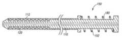
- FIG. 5depicts another device, that is similar to the device shown in FIGS. 1 and 2 , for delivering and deploying a prosthesis.
- the devicecomprises a delivery catheter 110 and a sheath 112 .
- a prosthesis 120may be held in a radially compressed configuration between the delivery catheter 110 and the sheath 112 .
- the delivery catheter 110is configured to expel the prosthesis 120 from the sheath lumen when the sheath 112 retracts over the delivery catheter 110 over a retraction distance.
- the devicemay include one or more additional features, as described above.
- a deployment assist mechanism 150may be provided.
- the assist mechanism 150is configured to provide a retraction force to the delivery and deployment device and may comprise an energy device, for example, a spring 152 .
- the term “spring”refers to any resilient or elastic body, device, or combination of bodies or devices that is capable of storing and releasing mechanical energy. Examples of springs include, but are not limited to, coil, helical, leaf, torsion, gas, and v-springs, and other elastic devices such as rubber, plastic, and metallic bands.
- One or more lock mechanisms, such as release pins,may be provided to fix the sheath 112 to the delivery catheter 110 and to prevent inadvertent sheath retraction.
- the spring 152includes a coil spring 180 .
- the distal end of the coil spring 180is coupled to the sheath 112 and the proximal end of the spring 180 is coupled to the delivery catheter 110 .
- the assist mechanism 150applies a retraction force to the delivery catheter 110 and the sheath 112 .
- the sheath 112may retract without additional input.
- the sheath 112may not retract without additional input.
- the assist mechanism 150may be configured to apply a retraction force that is greater than the retraction resistance over the entire retraction distance. Accordingly, no manual input is required to retract the sheath 112 .
- One advantage of such an assist mechanismis that no additional manual force is required to deploy the prosthesis 120 .
- the operatormay have little or no control over the rate and manner of deployment.
- an assist mechanism 150may be configured to apply a retraction force that is less than or equal to the retraction resistance over at least a portion of the retraction distance. Accordingly, the sheath 112 will not retract over a corresponding portion of the prosthesis 120 without input from the operator.
- An advantage of using such an assist mechanismis that it reduces the overall manual force required to retract the sheath 112 , but retains the fundamental characteristics and control of a “push-pull” type delivery and deployment device. Consequently, the operator may possess a high degree of control over the rate and manner of deployment, which may minimize the potential for early or inadvertent deployment.
- the magnitude of the additional force required to retract the sheath 112depends on the configuration of the delivery and deployment device and on the configuration of the assist mechanism 150 . For example, with a retraction resistance of approximately 22.5 pounds, and an assist mechanism retraction force of approximately 12.5 pounds, the additional force required may be approximately 10 pounds.
- the retraction resistance of a delivery and deployment devicemay vary over the retraction distance.
- An exemplary devicemay be provided that has a decaying retraction resistance (i.e., the retraction resistance decreases over the retraction distance) and combined with an assist mechanism 150 that is configured to apply a constant force over the entire retraction distance.
- the retraction forcemay be less than the retraction resistance over the entire retraction distance.
- the retraction forcemay be less than the retraction resistance during the initial stages of deployment, and higher than the retraction resistance during the final stages of deployment.
- the retraction forcemay be greater than the retraction resistance over the entire retraction distance.
- an assist mechanism 150may be configured to apply a variable force over the entire retraction distance.
- the assist mechanism 150may comprise an energy device, such as a spring 152 , that is configured to provide a retraction force that decreases as the sheath 112 retracts over the retraction distance.
- the assist mechanism 150may have a retraction force that is less than the retraction resistance over the entire retraction distance.
- the force decay of the assist mechanism 150corresponds with the resistance decay of the delivery and deployment device so that the additional force required to retract the sheath is generally constant over the retraction distance.
- FIG. 6illustrates a delivery and deployment device and another exemplary deployment assist mechanism 250 .
- the assist mechanism 250comprises a spring 252 disposed between the delivery catheter 210 and the sheath 212 .
- the spring 252 shown in FIG. 6comprises two coil springs 280 (e.g., watch springs) and two retractable cables 282 .
- the coil springs 280are fixed to the delivery catheter 210 .
- the distal ends of the cables 282are coupled to the sheath 212 , for example, via the haemostatic sealing device 219 .
- the proximal ends of the cables 282are coupled to the delivery catheter 210 , via springs 280 .
- the coil springs 280may transmit a retraction force to the sheath 212 via cables 282 .
- the spring 250may further comprise a spool 284 . As the sheath 212 retracts, tension releases in the springs 280 , and the cables 282 retract into the spool.
- the retraction resistance of the delivery and deployment devicemay be approximately 20 pounds and each of the coiled springs 280 may be configured to apply approximately 8 pounds of force continuously to the sheath 212 via cables 282 .
- a locking mechanism(not shown), such as a release pin, may be located along the length of the delivery and deployment device and prevent the sheath from retracting. When the release pin is removed, no sheath movement occurs until the operator provides approximately 4 pounds of additional force. When the operator stops applying force, sheath movement ceases. Deployment may be completed by the combined application of force by the assist mechanism 250 and by the operator. Alternatively, if during retraction, the retraction force of the assist mechanism exceeds the retraction resistance of the delivery and deployment device, deployment may be completed solely by the force of the assist mechanism, without additional operator input.
- FIG. 7illustrates a delivery and deployment device and another exemplary deployment assist mechanism 350 comprising an energy device.
- the mechanism 350comprises a cylinder 360 and a piston 362 disposed within the cylinder 362 .
- the proximal end of the cylinder 360is affixed to the delivery catheter 310 .
- the distal end of the cylinder 360slidingly engages the sheath 312 .
- the piston 362is affixed to the sheath 312 and is slidingly disposed within the cylinder 360 and about the delivery catheter 310 .
- the sheath 312 , cylinder 360 , and piston 362define a first annular chamber 364 .
- the delivery catheter 310 , cylinder 360 , and piston 362define a second annular chamber 366 .
- a seal(not shown) may be provided between the cylinder 360 and the sheath 312 , and/or between the cylinder 360 and the delivery catheter 310 , to provide a gas and/or fluid-tight seal for the chambers 364 , 366 .
- the first and second chambers 364 , 366may each comprise one or more valves. In the example shown in FIG.
- the first chamber 364comprises a valve 368 for providing communication to and from the first chamber, and a pair of valves 370 A, 370 B for providing communication to and from the second chamber. Additionally, or alternatively, a valve may be provided for providing communication between the first and second chambers.
- the assist mechanism 350comprises a gas spring.
- the first chamber 364may be configured to hold a compressible fluid, such as air.
- the first chamber 364contains the fluid under pressure so that the fluid exerts a distally-oriented force on the delivery catheter 310 (via the cylinder 360 ) and a proximally-oriented force on the sheath 312 (via the piston 362 ).
- the sheath 312may retract without additional input.
- the sheath 312may not retract without additional input. Accordingly, the operator may apply an additional force to retract the sheath 312 .
- the piston 362slides proximally within the cylinder 360 , causing the volume of the first chamber 364 to increase and the pressure within the first chamber 364 to decrease.
- the volume of the second chamber 366decreases. If the second chamber 366 is vented, for example, if the valves 370 A, 370 B are open, the pressure within the second chamber 366 may remain generally constant. Thus, the resistance within the gas spring may be generally constant over the retraction distance. If, however, the second chamber 366 is sealed, for example if the valves 370 A, 370 B are closed, the pressure within the second chamber 366 may increase, causing the resistance within the gas spring to increase.
- a delivery and assist mechanism with an initial retraction resistance of approximately 22.5 poundsmay be combined with an assist mechanism 350 comprising a gas spring, as described above.
- the first chamber 364is charged with pressurized fluid, the second chamber 366 is vented via valves 370 A, 370 B, and the assist mechanism provides a retraction force of approximately 12.5 pounds.
- the operatormay apply approximately 10 pounds of force to retract the sheath 312 .
- the piston 362slides proximally within the cylinder 360 and the pressure within the first chamber 364 decreases.
- the retraction forceis generally lower than the retraction resistance. If, during later stages of deployment, the retraction force exceeds the retraction resistance, the sheath 312 will retract without input from the operator.
- the operatormay close one or more of the valves 370 A, 370 B, to increase the pressure within the second chamber 366 , and slow or brake the retraction.
- first valve 370 Amay couple the second chamber 366 to a pressure source (not shown) and the second valve 370 B may be a vent.
- the second valve 370 BWhen the second valve 370 B is closed, the second chamber 366 may be pressurized via the pressure source (not shown).
- the assist mechanism 350may act as a brake.
- the second valve 370 Bmay be opened to depressurize the second chamber 366 and release the brake.
- an assist mechanism 350may be provided where the first and second chambers 364 , 366 each comprise a compression spring.
- the first chamber 364may comprise a coil spring (not shown) disposed between the distal end of the cylinder 360 and the piston 362 and the second chamber 366 may comprise a pressurized fluid.
- the assist mechanism 350may comprise a valve (not shown) for providing fluid communication between the second chamber 366 and the first chamber 364 . Prior to deployment, the first chamber 364 is evacuated, the second chamber 366 is pressurized, the valve between the chambers is closed, and the coil spring (not shown) is compressed. In this configuration, the assist mechanism 350 does not apply a retraction force to the delivery and deployment device.
- fluidmay move from the second chamber 366 to the lower pressure first chamber 364 , thus increasing the pressure within the first chamber 364 , decreasing the pressure in the second chamber 366 , decreasing the resistance on the compression spring, and increasing the retraction force of the assist mechanism 350 .
- the assist mechanism 350may comprise a hydraulic cylinder and include a non-compressible fluid, for example, water or saline solution.
- the piston 362moves within the cylinder 360 by transferring fluid into the first chamber 364 .
- the fluidmay be transferred, for example, from a reservoir (not shown) via valve 368 .
- an inflation-deflation devicesuch as the SphereTM Inflation Device by Cook, Incorporated, Bloomington, Ind. USA, could be used to pressurize the first chamber 364 .
- the fluidmay be transferred from the second chamber 366 to the first chamber 364 as described above.
- a control systemmay be provided for controlling the pressure within the first and/or second chambers.
- the control systemmay comprise, for example, a computer or other suitable input-output device that is capable of predicting or measuring the retraction resistance and actuating one or more valves to effect the retraction force of the assist mechanism.
- the control systemmay comprise a strain gage that measures the retraction resistance during deployment.
- stress-strain datai.e., resistance as a function of retraction distance
- a delivery and deployment devicecould be empirically or experimentally derived and input into the computer.
- FIG. 8depicts another deployment assist mechanism 450 .
- Spring 452is provided and comprises a coil spring 480 and a gas spring 482 .
- the distal end of the coil spring 480is coupled to the sheath 412 and the proximal end is coupled to the delivery catheter 410 .
- the gas spring 482comprises a cylinder 460 , and a piston 462 disposed within the cylinder 460 .
- the proximal end of the cylinder 460is affixed to the delivery catheter 410 and the piston 462 is affixed to the sheath 412 .
- the piston 462is slidably disposed within the cylinder 460 and about the delivery catheter 410 .
- the delivery catheter 410 , cylinder 460 , and piston 462define an annular chamber 464 .
- the cylinder 460may comprise one or more valves 468 , as described above.
- the coil spring 480may be configured to apply approximately 10 pounds of retraction force to a delivery and deployment device having an initial retraction resistance of 15 pounds. Accordingly, the operator will have to apply approximately 5 pounds of additional force to retract the sheath 412 .
- both the retraction resistance of the delivery and deployment device and the retraction force of the coil spring 480may decay over the retraction distance. If the retraction force decays in proportion with the decay of the retraction resistance, the additional force required of the operator will be generally constant over the retraction distance. If, however, the coil spring force decays too quickly or too slowly, the additional force required by the operator will increase or decrease over the retraction distance.
- the gas spring 482may be provided and operated to selectively resist or assist the restoring force of the coil spring 480 , thus selectively decreasing or increasing the retraction force of the assist mechanism 450 .
- the retraction forcemay be increased by decreasing the pressure in the chamber 464 (e.g., by pulling a vacuum via valve 468 ).
- the retraction forcemay be decreased by increasing the pressure in the chamber 464 .
- the gas springmay act as a brake.
- the assist mechanism 450may comprise a control system (not shown), as described above, for controlling the pressure in the chamber 464 .
- FIG. 9depicts another delivery and deployment device that includes a delivery catheter 510 , a sheath 512 , and a haemostatic sealing device 519 for controlling blood loss between the delivery catheter 510 and the sheath 512 .
- the delivery and deployment devicepreferably comprises a deployment assist mechanism (not shown), as described above.
- a brake mechanism 590may be provided for braking the retraction of the sheath 512 during deployment.
- the brake mechanism 590may comprise a brake pad 592 affixed to the sheath 512 that can be maneuvered to selectively engage and disengage the delivery catheter 510 .
- the brake pad 592may comprise, for example, a rubber or plastic gasket that is frictionally engageable with the delivery catheter 510 .
- the brake pad 592is disposed within a housing 594 that is coupled to sheath 512 via the haemostatic sealing device 519 .
- the brake mechanism 590may comprise a flexible handle that is configured to urge the brake pad 592 against the delivery catheter 510 when squeezed or otherwise compressed.
- the brake pad 592may comprise a hydraulically or pneumatically expandable gasket, where the brake pad 592 engages the delivery catheter 510 when the gasket expands.
- a brake mechanismmay be used in conjunction with a deployment assist mechanism as a power-release mechanism.
- the brake mechanismmay prevent the release of power from the assist mechanism so that the sheath may be retracted by releasing the brake.
- a brake mechanismmay be used as a power-control mechanism.
- the brake mechanismmay allow the release of power from the assist mechanism and the sheath may be controlled via selective application of the brake.
- the brake mechanismmay be actuated manually by the operator, or automatically, for example, by a control system (not shown), as described above.
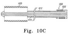
- FIGS. 10A-10Cillustrate a method of deploying a prosthesis in a body lumen.
- a guidewire(not shown) is introduced into the body lumen and advanced until the tip is beyond the region where the prosthesis 620 will be deployed.
- the delivery and deployment deviceis then inserted into the body lumen over the guide wire (not shown) and positioned in the treatment area by radiographic techniques that are generally known in the art.
- the prosthesis 620is fully retained in the delivery and deployment device in a radially-constrained configuration by the sheath 612 as shown in FIG. 10A .
- the deviceis ready for deployment. If the delivery and assist mechanism comprises a lock mechanism, it may be removed.
- the operatormay use a deployment assist mechanism 650 .
- the assist mechanism 650comprises a spring 652 , although any suitable energy device may be used.
- the assist mechanism 650applies a retraction force to the delivery and deployment device.
- the retraction resistanceis initially greater than the retraction force applied by the assist mechanism 650 . Accordingly, the sheath will not retract until the operator applies an additional retraction force.
- the operatormay retract the sheath 612 , for example, by pulling the sheath 612 in a proximal direction and pushing the delivery catheter 610 in a distal direction. As the sheath 612 retracts, the prosthesis 620 becomes exposed and is allowed to expand into the body lumen. If the prosthesis 620 is self-expanding, it may expand simply by removing the sheath, as shown in FIG. 10B .
- the delivery catheter 610is held steady relative to the sheath 612 during deployment.
- the operatormay manually fix the position of the delivery catheter 610 .
- a delivery fixture(not shown) may be provided to hold the delivery catheter 610 steady during deployment.
- a brake mechanismmay be provided, as described above.
- FIG. 10Cshows the delivery and deployment device in a fully deployed state, where the sheath 612 is fully retracted over the retraction distance and the prosthesis 620 is expanded within the body lumen.
- the delivery and deployment device and the guide wiremay now be removed from the body lumen.
Landscapes
- Health & Medical Sciences (AREA)
- Engineering & Computer Science (AREA)
- Biomedical Technology (AREA)
- Cardiology (AREA)
- Oral & Maxillofacial Surgery (AREA)
- Transplantation (AREA)
- Heart & Thoracic Surgery (AREA)
- Vascular Medicine (AREA)
- Life Sciences & Earth Sciences (AREA)
- Animal Behavior & Ethology (AREA)
- General Health & Medical Sciences (AREA)
- Public Health (AREA)
- Veterinary Medicine (AREA)
- Media Introduction/Drainage Providing Device (AREA)
Abstract
Description
Claims (19)
Priority Applications (1)
| Application Number | Priority Date | Filing Date | Title |
|---|---|---|---|
| US12/173,277US9119742B2 (en) | 2007-07-16 | 2008-07-15 | Prosthesis delivery and deployment device |
Applications Claiming Priority (2)
| Application Number | Priority Date | Filing Date | Title |
|---|---|---|---|
| US95000107P | 2007-07-16 | 2007-07-16 | |
| US12/173,277US9119742B2 (en) | 2007-07-16 | 2008-07-15 | Prosthesis delivery and deployment device |
Publications (2)
| Publication Number | Publication Date |
|---|---|
| US20090024137A1 US20090024137A1 (en) | 2009-01-22 |
| US9119742B2true US9119742B2 (en) | 2015-09-01 |
Family
ID=39929552
Family Applications (1)
| Application Number | Title | Priority Date | Filing Date |
|---|---|---|---|
| US12/173,277Active2031-02-01US9119742B2 (en) | 2007-07-16 | 2008-07-15 | Prosthesis delivery and deployment device |
Country Status (3)
| Country | Link |
|---|---|
| US (1) | US9119742B2 (en) |
| EP (1) | EP2178470B1 (en) |
| WO (1) | WO2009011866A1 (en) |
Cited By (6)
| Publication number | Priority date | Publication date | Assignee | Title |
|---|---|---|---|---|
| US20130304181A1 (en)* | 2012-05-09 | 2013-11-14 | Michael L. Green | Catheter having hydraulic actuator with tandem chambers |
| US10039659B2 (en) | 2012-05-09 | 2018-08-07 | Abbott Cardiovascular Systems Inc. | Catheter having hydraulic actuator |
| US10327932B2 (en) | 2013-03-12 | 2019-06-25 | Abbott Cardiovascular Systems Inc. | Catheter having hydraulic actuator and locking system |
| US10420662B2 (en) | 2013-03-12 | 2019-09-24 | Abbott Cardiovascular Systems Inc. | Catheter having movable tubular structure and proximal stopper |
| US10531971B2 (en) | 2013-03-12 | 2020-01-14 | Abbott Cardiovascular System Inc. | Balloon catheter having hydraulic actuator |
| US10675164B2 (en) | 2012-05-09 | 2020-06-09 | Abbott Cardiovascular Systems Inc. | Catheter having dual balloon hydraulic actuator |
Families Citing this family (38)
| Publication number | Priority date | Publication date | Assignee | Title |
|---|---|---|---|---|
| JP5181211B2 (en)* | 2005-12-23 | 2013-04-10 | クック・メディカル・テクノロジーズ・リミテッド・ライアビリティ・カンパニー | Trigger wire release mechanism and introducer for prosthesis including the same |
| US11026822B2 (en) | 2006-01-13 | 2021-06-08 | C. R. Bard, Inc. | Stent delivery system |
| GB0615658D0 (en) | 2006-08-07 | 2006-09-13 | Angiomed Ag | Hand-held actuator device |
| GB0713497D0 (en) | 2007-07-11 | 2007-08-22 | Angiomed Ag | Device for catheter sheath retraction |
| US8845710B2 (en)* | 2007-11-30 | 2014-09-30 | Cook Medical Technologies Llc | Method and apparatus for introducing intraluminal prostheses |
| EP2328524B1 (en)* | 2008-07-02 | 2019-01-16 | Cook Medical Technologies LLC | Deployment assembly |
| AU2009200350B1 (en)* | 2009-02-02 | 2009-07-16 | Cook Incorporated | Preloaded stent graft delivery device |
| GB0906065D0 (en) | 2009-04-07 | 2009-05-20 | Angiomed Ag | Delivery system for a prosthesis |
| DE102009019823A1 (en)* | 2009-05-04 | 2010-11-11 | Acancis Gmbh & Co. Kg | Medical catheter, medical system with such a catheter and charging device for producing such a catheter |
| DE102009055969A1 (en)* | 2009-11-27 | 2011-06-01 | Transcatheter Technologies Gmbh | Device and set for folding or unfolding a medical implant and method |
| JP2013535259A (en)* | 2010-07-21 | 2013-09-12 | クック メディカル テクノロジーズ エルエルシー | Control mechanism for stent delivery system |
| US8814931B2 (en) | 2010-08-24 | 2014-08-26 | St. Jude Medical, Cardiology Division, Inc. | Staged deployment devices and methods for transcatheter heart valve delivery systems |
| WO2012036741A2 (en) | 2010-09-17 | 2012-03-22 | St. Jude Medical, Cardiology Division, Inc. | Staged deployment devices and methods for transcatheter heart valve delivery |
| GB201017834D0 (en)* | 2010-10-21 | 2010-12-01 | Angiomed Ag | System to deliver a bodily implant |
| US9717593B2 (en) | 2011-02-01 | 2017-08-01 | St. Jude Medical, Cardiology Division, Inc. | Leaflet suturing to commissure points for prosthetic heart valve |
| GB2488107B (en)* | 2011-02-11 | 2013-03-06 | Cook Medical Technologies Llc | Drive assembly for facilitating deployment of an implantable medical device |
| GB2492002B (en)* | 2011-02-11 | 2013-03-06 | Cook Medical Technologies Llc | Drive assembly for facilitating deployment of an implantable medical device |
| US9440059B2 (en) | 2011-03-18 | 2016-09-13 | Cook Medical Technologies Llc | Adjustable diameter hemostatic valve |
| PL2724690T3 (en)* | 2011-06-01 | 2017-01-31 | Nvt Ag | Cardiac valve prosthesis deployment system |
| US9060860B2 (en) | 2011-08-18 | 2015-06-23 | St. Jude Medical, Cardiology Division, Inc. | Devices and methods for transcatheter heart valve delivery |
| US8852258B2 (en) | 2011-10-24 | 2014-10-07 | Novostent Corporation | Catheter assembly with user-assisting handle |
| EP2596769A1 (en)* | 2011-11-24 | 2013-05-29 | Biotronik AG | Release device for releasing a medical implant from a catheter and catheter comprising a release device |
| US9579198B2 (en) | 2012-03-01 | 2017-02-28 | Twelve, Inc. | Hydraulic delivery systems for prosthetic heart valve devices and associated methods |
| CA2874568C (en)* | 2012-10-30 | 2021-06-22 | Angiomed Gmbh & Co. Medizintechnik Kg | Catheter delivery system to release a self-expanding implant |
| CH707319A1 (en)* | 2012-12-11 | 2014-06-13 | Carag Ag | Stent applicator. |
| WO2015073287A1 (en) | 2013-11-12 | 2015-05-21 | St. Jude Medical, Cardiology Division, Inc. | Pneumatically power-assisted tavi delivery system |
| KR101514055B1 (en)* | 2013-12-17 | 2015-04-21 | 주식회사 스텐다드싸이텍 | Catheter for common hepatic duct |
| US10492857B2 (en)* | 2015-08-06 | 2019-12-03 | Boston Scientific Scimed Inc | Deployment control apparatus for a catheter with a deployable array |
| WO2018102525A1 (en) | 2016-12-02 | 2018-06-07 | St. Jude Medical, Cardiology Division, Inc. | Transcatheter delivery system with two modes of actuation |
| WO2018102520A1 (en) | 2016-12-02 | 2018-06-07 | St. Jude Medical, Cardiology Division, Inc. | Transcatheter delivery system with transverse wheel actuation |
| US10575950B2 (en) | 2017-04-18 | 2020-03-03 | Twelve, Inc. | Hydraulic systems for delivering prosthetic heart valve devices and associated methods |
| WO2018213091A1 (en) | 2017-05-15 | 2018-11-22 | St. Jude Medical, Cardiology Division, Inc. | Transcatheter delivery system with wheel actuation |
| US10646338B2 (en) | 2017-06-02 | 2020-05-12 | Twelve, Inc. | Delivery systems with telescoping capsules for deploying prosthetic heart valve devices and associated methods |
| US11096810B2 (en) | 2017-11-29 | 2021-08-24 | Cook Medical Technologies Llc | Preloaded pusher tip for endografts |
| US10441449B1 (en) | 2018-05-30 | 2019-10-15 | Vesper Medical, Inc. | Rotary handle stent delivery system and method |
| US10449073B1 (en) | 2018-09-18 | 2019-10-22 | Vesper Medical, Inc. | Rotary handle stent delivery system and method |
| US11219541B2 (en) | 2020-05-21 | 2022-01-11 | Vesper Medical, Inc. | Wheel lock for thumbwheel actuated device |
| CN118217055A (en)* | 2022-12-21 | 2024-06-21 | 深圳市健心医疗科技有限公司 | Conveyor and conveying system |
Citations (61)
| Publication number | Priority date | Publication date | Assignee | Title |
|---|---|---|---|---|
| US4562596A (en) | 1984-04-25 | 1986-01-07 | Elliot Kornberg | Aortic graft, device and method for performing an intraluminal abdominal aortic aneurysm repair |
| US4665918A (en) | 1986-01-06 | 1987-05-19 | Garza Gilbert A | Prosthesis system and method |
| US4921484A (en) | 1988-07-25 | 1990-05-01 | Cordis Corporation | Mesh balloon catheter device |
| US5078720A (en) | 1990-05-02 | 1992-01-07 | American Medical Systems, Inc. | Stent placement instrument and method |
| US5092877A (en) | 1988-09-01 | 1992-03-03 | Corvita Corporation | Radially expandable endoprosthesis |
| US5201757A (en) | 1992-04-03 | 1993-04-13 | Schneider (Usa) Inc. | Medial region deployment of radially self-expanding stents |
| US5380304A (en) | 1991-08-07 | 1995-01-10 | Cook Incorporated | Flexible, kink-resistant, introducer sheath and method of manufacture |
| WO1995011055A1 (en) | 1993-10-22 | 1995-04-27 | Scimed Lifesystems, Inc. | Improved stent delivery apparatus and method |
| US5415664A (en) | 1994-03-30 | 1995-05-16 | Corvita Corporation | Method and apparatus for introducing a stent or a stent-graft |
| US5445646A (en) | 1993-10-22 | 1995-08-29 | Scimed Lifesystems, Inc. | Single layer hydraulic sheath stent delivery apparatus and method |
| US5534007A (en) | 1995-05-18 | 1996-07-09 | Scimed Life Systems, Inc. | Stent deployment catheter with collapsible sheath |
| US5626603A (en) | 1994-10-05 | 1997-05-06 | Fogazzi Di Ventureli Andrea & C. S.N.C. | Hydraulic stent inserter |
| US5683451A (en) | 1994-06-08 | 1997-11-04 | Cardiovascular Concepts, Inc. | Apparatus and methods for deployment release of intraluminal prostheses |
| US5690644A (en) | 1992-12-30 | 1997-11-25 | Schneider (Usa) Inc. | Apparatus for deploying body implantable stent |
| US5693086A (en) | 1994-02-09 | 1997-12-02 | Boston Scientific Technology, Inc. | Apparatus for delivering an endoluminal stent or prosthesis |
| US5817101A (en) | 1997-03-13 | 1998-10-06 | Schneider (Usa) Inc | Fluid actuated stent delivery system |
| US5824041A (en) | 1994-06-08 | 1998-10-20 | Medtronic, Inc. | Apparatus and methods for placement and repositioning of intraluminal prostheses |
| WO1998053761A1 (en) | 1997-05-26 | 1998-12-03 | William A. Cook Australia Pty. Ltd. | A prosthesis and a method and means of deploying a prosthesis |
| US5906619A (en) | 1997-07-24 | 1999-05-25 | Medtronic, Inc. | Disposable delivery device for endoluminal prostheses |
| US5968052A (en) | 1996-11-27 | 1999-10-19 | Scimed Life Systems Inc. | Pull back stent delivery system with pistol grip retraction handle |
| US6004328A (en) | 1997-06-19 | 1999-12-21 | Solar; Ronald J. | Radially expandable intraluminal stent and delivery catheter therefore and method of using the same |
| US6113608A (en) | 1998-11-20 | 2000-09-05 | Scimed Life Systems, Inc. | Stent delivery device |
| US6123723A (en) | 1998-02-26 | 2000-09-26 | Board Of Regents, The University Of Texas System | Delivery system and method for depolyment and endovascular assembly of multi-stage stent graft |
| EP1078611A1 (en) | 1999-08-24 | 2001-02-28 | Novatech SA | Intravascular prosthesis and system for deployment of same |
| US6203550B1 (en) | 1998-09-30 | 2001-03-20 | Medtronic, Inc. | Disposable delivery device for endoluminal prostheses |
| US6206888B1 (en)* | 1997-10-01 | 2001-03-27 | Scimed Life Systems, Inc. | Stent delivery system using shape memory retraction |
| US6254611B1 (en) | 1996-09-27 | 2001-07-03 | Scimed Life Systems, Inc. | Stent deployment catheter with midshaft seal |
| US6287315B1 (en) | 1995-10-30 | 2001-09-11 | World Medical Manufacturing Corporation | Apparatus for delivering an endoluminal prosthesis |
| US20010034514A1 (en) | 2000-03-23 | 2001-10-25 | Cook Incorporated | Introducer sheath |
| US20020045929A1 (en) | 2000-10-13 | 2002-04-18 | Juan-Carlos Diaz | Stent delivery system with hydraulic deployment |
| US6514261B1 (en) | 1998-09-30 | 2003-02-04 | Impra, Inc. | Delivery mechanism for implantable stent |
| US20030028236A1 (en)* | 2001-07-31 | 2003-02-06 | Gillick Matthew J. | Control device and mechanism for deploying a self-expanding medical device |
| US20030109886A1 (en) | 2001-06-27 | 2003-06-12 | Martin Keegan | Catheter |
| US6599296B1 (en)* | 2001-07-27 | 2003-07-29 | Advanced Cardiovascular Systems, Inc. | Ratcheting handle for intraluminal catheter systems |
| US6626934B2 (en) | 1999-06-14 | 2003-09-30 | Scimed Life Systems, Inc. | Stent delivery system |
| US6652480B1 (en) | 1997-03-06 | 2003-11-25 | Medtronic Ave., Inc. | Methods for reducing distal embolization |
| US6669716B1 (en) | 1998-03-31 | 2003-12-30 | Salviac Limited | Delivery catheter |
| US20040093063A1 (en) | 2002-06-07 | 2004-05-13 | Wright Michael T. | Controlled deployment delivery system |
| US20040098079A1 (en) | 2002-06-28 | 2004-05-20 | Cook Incorporated | Thoracic aortic stent graft deployment device |
| US20040106974A1 (en) | 2002-06-28 | 2004-06-03 | Cook Incorporated | Thoracic introducer |
| US20040127912A1 (en) | 2002-12-31 | 2004-07-01 | Dmitry Rabkin | Stent delivery system |
| US20040133264A1 (en) | 2000-02-04 | 2004-07-08 | Moore Scott T. | Stent introducer apparatus |
| US20040148008A1 (en) | 2003-01-24 | 2004-07-29 | Goodson Harry B. | Stent-graft delivery system |
| US6858034B1 (en) | 1999-05-20 | 2005-02-22 | Scimed Life Systems, Inc. | Stent delivery system for prevention of kinking, and method of loading and using same |
| US20050060018A1 (en) | 2003-09-16 | 2005-03-17 | Cook Incorporated | Prosthesis deployment system |
| US20050080476A1 (en) | 2003-10-09 | 2005-04-14 | Gunderson Richard C. | Medical device delivery system |
| US20050085890A1 (en) | 2003-10-15 | 2005-04-21 | Cook Incorporated | Prosthesis deployment system retention device |
| US20050090887A1 (en) | 2003-10-22 | 2005-04-28 | Pryor Jack D. | Delivery system for long self-expanding stents |
| US6911039B2 (en) | 2002-04-23 | 2005-06-28 | Medtronic Vascular, Inc. | Integrated mechanical handle with quick slide mechanism |
| WO2005107644A1 (en) | 2004-04-27 | 2005-11-17 | Boston Scientific Limited | Stent delivery system |
| US20050273151A1 (en) | 2004-06-04 | 2005-12-08 | John Fulkerson | Stent delivery system |
| US20060142833A1 (en)* | 2002-08-07 | 2006-06-29 | Randolf Von Oepen | Apparatus for delivery and deployment of an expandable stent within a blood vessel |
| US7105016B2 (en) | 2002-04-23 | 2006-09-12 | Medtronic Vascular, Inc. | Integrated mechanical handle with quick slide mechanism |
| US20060282150A1 (en) | 2005-06-08 | 2006-12-14 | Xtent, Inc. | Devices and methods for operating and controlling interventional apparatus |
| US20060282152A1 (en) | 2005-06-14 | 2006-12-14 | Dagmar Beyerlein | Delivery system for a device such as a stent |
| US20060286145A1 (en) | 2005-06-07 | 2006-12-21 | Salviac Limited | Deployment system for a medical device |
| US20070060999A1 (en) | 2005-08-17 | 2007-03-15 | Michael Randall | Variable speed stent delivery system |
| WO2007084370A1 (en) | 2006-01-13 | 2007-07-26 | C.R. Bard, Inc. | Stent delivery system |
| US20070233222A1 (en) | 2006-02-21 | 2007-10-04 | Med Institute, Inc. | Split sheath deployment system |
| US20070255390A1 (en) | 2006-04-27 | 2007-11-01 | William A. Cook Australia Pty. Ltd. | Rotary handle for controlled sequential deployment device |
| US20070293934A1 (en) | 2006-06-19 | 2007-12-20 | Med Institute, Inc. | Prosthesis Delivery and Deployment Device |
Family Cites Families (1)
| Publication number | Priority date | Publication date | Assignee | Title |
|---|---|---|---|---|
| JP2002270282A (en)* | 2001-03-12 | 2002-09-20 | Yazaki Corp | Waterproof connector and terminal insertion method of waterproof connector |
- 2008
- 2008-07-15USUS12/173,277patent/US9119742B2/enactiveActive
- 2008-07-16EPEP20080794519patent/EP2178470B1/enactiveActive
- 2008-07-16WOPCT/US2008/008677patent/WO2009011866A1/enactiveApplication Filing
Patent Citations (73)
| Publication number | Priority date | Publication date | Assignee | Title |
|---|---|---|---|---|
| US4562596A (en) | 1984-04-25 | 1986-01-07 | Elliot Kornberg | Aortic graft, device and method for performing an intraluminal abdominal aortic aneurysm repair |
| US4665918A (en) | 1986-01-06 | 1987-05-19 | Garza Gilbert A | Prosthesis system and method |
| US4921484A (en) | 1988-07-25 | 1990-05-01 | Cordis Corporation | Mesh balloon catheter device |
| US5092877A (en) | 1988-09-01 | 1992-03-03 | Corvita Corporation | Radially expandable endoprosthesis |
| US5078720A (en) | 1990-05-02 | 1992-01-07 | American Medical Systems, Inc. | Stent placement instrument and method |
| US5380304A (en) | 1991-08-07 | 1995-01-10 | Cook Incorporated | Flexible, kink-resistant, introducer sheath and method of manufacture |
| US5201757A (en) | 1992-04-03 | 1993-04-13 | Schneider (Usa) Inc. | Medial region deployment of radially self-expanding stents |
| US5690644A (en) | 1992-12-30 | 1997-11-25 | Schneider (Usa) Inc. | Apparatus for deploying body implantable stent |
| WO1995011055A1 (en) | 1993-10-22 | 1995-04-27 | Scimed Lifesystems, Inc. | Improved stent delivery apparatus and method |
| US5445646A (en) | 1993-10-22 | 1995-08-29 | Scimed Lifesystems, Inc. | Single layer hydraulic sheath stent delivery apparatus and method |
| US5693086A (en) | 1994-02-09 | 1997-12-02 | Boston Scientific Technology, Inc. | Apparatus for delivering an endoluminal stent or prosthesis |
| US5415664A (en) | 1994-03-30 | 1995-05-16 | Corvita Corporation | Method and apparatus for introducing a stent or a stent-graft |
| US5683451A (en) | 1994-06-08 | 1997-11-04 | Cardiovascular Concepts, Inc. | Apparatus and methods for deployment release of intraluminal prostheses |
| US6024763A (en) | 1994-06-08 | 2000-02-15 | Medtronic, Inc. | Apparatus and methods for deployment release of intraluminal prostheses |
| US6350278B1 (en) | 1994-06-08 | 2002-02-26 | Medtronic Ave, Inc. | Apparatus and methods for placement and repositioning of intraluminal prostheses |
| US5824041A (en) | 1994-06-08 | 1998-10-20 | Medtronic, Inc. | Apparatus and methods for placement and repositioning of intraluminal prostheses |
| EP0696447B1 (en) | 1994-08-12 | 2000-01-19 | Cardiovascular Concepts, Inc. | Apparatus for deployment release of intraluminal prostheses |
| US5626603A (en) | 1994-10-05 | 1997-05-06 | Fogazzi Di Ventureli Andrea & C. S.N.C. | Hydraulic stent inserter |
| US5534007A (en) | 1995-05-18 | 1996-07-09 | Scimed Life Systems, Inc. | Stent deployment catheter with collapsible sheath |
| US6287315B1 (en) | 1995-10-30 | 2001-09-11 | World Medical Manufacturing Corporation | Apparatus for delivering an endoluminal prosthesis |
| US6254611B1 (en) | 1996-09-27 | 2001-07-03 | Scimed Life Systems, Inc. | Stent deployment catheter with midshaft seal |
| US5968052A (en) | 1996-11-27 | 1999-10-19 | Scimed Life Systems Inc. | Pull back stent delivery system with pistol grip retraction handle |
| US6652480B1 (en) | 1997-03-06 | 2003-11-25 | Medtronic Ave., Inc. | Methods for reducing distal embolization |
| US5817101A (en) | 1997-03-13 | 1998-10-06 | Schneider (Usa) Inc | Fluid actuated stent delivery system |
| US6605109B2 (en) | 1997-03-13 | 2003-08-12 | Scimed Life Systems, Inc | Fluid actuated stent delivery system |
| US6056759A (en) | 1997-03-13 | 2000-05-02 | Schneider (Usa) Inc. | Fluid actuated stent delivery system |
| WO1998053761A1 (en) | 1997-05-26 | 1998-12-03 | William A. Cook Australia Pty. Ltd. | A prosthesis and a method and means of deploying a prosthesis |
| US6004328A (en) | 1997-06-19 | 1999-12-21 | Solar; Ronald J. | Radially expandable intraluminal stent and delivery catheter therefore and method of using the same |
| US5906619A (en) | 1997-07-24 | 1999-05-25 | Medtronic, Inc. | Disposable delivery device for endoluminal prostheses |
| US6206888B1 (en)* | 1997-10-01 | 2001-03-27 | Scimed Life Systems, Inc. | Stent delivery system using shape memory retraction |
| US20010012944A1 (en) | 1997-10-01 | 2001-08-09 | Bicek Andrew D. | Stent delivery system using shape memory retraction |
| US6579297B2 (en) | 1997-10-01 | 2003-06-17 | Scimed Life Systems, Inc. | Stent delivery system using shape memory retraction |
| US6123723A (en) | 1998-02-26 | 2000-09-26 | Board Of Regents, The University Of Texas System | Delivery system and method for depolyment and endovascular assembly of multi-stage stent graft |
| US6669716B1 (en) | 1998-03-31 | 2003-12-30 | Salviac Limited | Delivery catheter |
| US6203550B1 (en) | 1998-09-30 | 2001-03-20 | Medtronic, Inc. | Disposable delivery device for endoluminal prostheses |
| US7122050B2 (en) | 1998-09-30 | 2006-10-17 | Bard Peripheral Vascular, Inc. | Delivery mechanism for implantable stent |
| US6514261B1 (en) | 1998-09-30 | 2003-02-04 | Impra, Inc. | Delivery mechanism for implantable stent |
| US6113608A (en) | 1998-11-20 | 2000-09-05 | Scimed Life Systems, Inc. | Stent delivery device |
| US6858034B1 (en) | 1999-05-20 | 2005-02-22 | Scimed Life Systems, Inc. | Stent delivery system for prevention of kinking, and method of loading and using same |
| US6626934B2 (en) | 1999-06-14 | 2003-09-30 | Scimed Life Systems, Inc. | Stent delivery system |
| US6402760B1 (en)* | 1999-08-24 | 2002-06-11 | Novatech Sa | Device for causing the release of an object, particularly a prosthesis, into a human or animal passage, and implantation system comprising a catheter and such a device |
| EP1078611A1 (en) | 1999-08-24 | 2001-02-28 | Novatech SA | Intravascular prosthesis and system for deployment of same |
| US20040133264A1 (en) | 2000-02-04 | 2004-07-08 | Moore Scott T. | Stent introducer apparatus |
| US20010034514A1 (en) | 2000-03-23 | 2001-10-25 | Cook Incorporated | Introducer sheath |
| US20020045929A1 (en) | 2000-10-13 | 2002-04-18 | Juan-Carlos Diaz | Stent delivery system with hydraulic deployment |
| US20030109886A1 (en) | 2001-06-27 | 2003-06-12 | Martin Keegan | Catheter |
| US6599296B1 (en)* | 2001-07-27 | 2003-07-29 | Advanced Cardiovascular Systems, Inc. | Ratcheting handle for intraluminal catheter systems |
| US20030028236A1 (en)* | 2001-07-31 | 2003-02-06 | Gillick Matthew J. | Control device and mechanism for deploying a self-expanding medical device |
| US6911039B2 (en) | 2002-04-23 | 2005-06-28 | Medtronic Vascular, Inc. | Integrated mechanical handle with quick slide mechanism |
| US7105016B2 (en) | 2002-04-23 | 2006-09-12 | Medtronic Vascular, Inc. | Integrated mechanical handle with quick slide mechanism |
| US7419501B2 (en) | 2002-04-23 | 2008-09-02 | Medtronic Vascular, Inc. | Integrated mechanical handle with quick slide mechanism |
| US20080021538A1 (en) | 2002-06-07 | 2008-01-24 | Medtronic Vascular, Inc. | Controlled Deployment Delivery System |
| US20040093063A1 (en) | 2002-06-07 | 2004-05-13 | Wright Michael T. | Controlled deployment delivery system |
| US20040106974A1 (en) | 2002-06-28 | 2004-06-03 | Cook Incorporated | Thoracic introducer |
| US20040098079A1 (en) | 2002-06-28 | 2004-05-20 | Cook Incorporated | Thoracic aortic stent graft deployment device |
| US20060142833A1 (en)* | 2002-08-07 | 2006-06-29 | Randolf Von Oepen | Apparatus for delivery and deployment of an expandable stent within a blood vessel |
| US6849084B2 (en) | 2002-12-31 | 2005-02-01 | Intek Technology L.L.C. | Stent delivery system |
| US20040127912A1 (en) | 2002-12-31 | 2004-07-01 | Dmitry Rabkin | Stent delivery system |
| US20040148008A1 (en) | 2003-01-24 | 2004-07-29 | Goodson Harry B. | Stent-graft delivery system |
| US20050060018A1 (en) | 2003-09-16 | 2005-03-17 | Cook Incorporated | Prosthesis deployment system |
| US20050080476A1 (en) | 2003-10-09 | 2005-04-14 | Gunderson Richard C. | Medical device delivery system |
| US20050085890A1 (en) | 2003-10-15 | 2005-04-21 | Cook Incorporated | Prosthesis deployment system retention device |
| US20050090887A1 (en) | 2003-10-22 | 2005-04-28 | Pryor Jack D. | Delivery system for long self-expanding stents |
| WO2005107644A1 (en) | 2004-04-27 | 2005-11-17 | Boston Scientific Limited | Stent delivery system |
| US20050273151A1 (en) | 2004-06-04 | 2005-12-08 | John Fulkerson | Stent delivery system |
| US20060286145A1 (en) | 2005-06-07 | 2006-12-21 | Salviac Limited | Deployment system for a medical device |
| US20060282150A1 (en) | 2005-06-08 | 2006-12-14 | Xtent, Inc. | Devices and methods for operating and controlling interventional apparatus |
| US20060282152A1 (en) | 2005-06-14 | 2006-12-14 | Dagmar Beyerlein | Delivery system for a device such as a stent |
| US20070060999A1 (en) | 2005-08-17 | 2007-03-15 | Michael Randall | Variable speed stent delivery system |
| WO2007084370A1 (en) | 2006-01-13 | 2007-07-26 | C.R. Bard, Inc. | Stent delivery system |
| US20070233222A1 (en) | 2006-02-21 | 2007-10-04 | Med Institute, Inc. | Split sheath deployment system |
| US20070255390A1 (en) | 2006-04-27 | 2007-11-01 | William A. Cook Australia Pty. Ltd. | Rotary handle for controlled sequential deployment device |
| US20070293934A1 (en) | 2006-06-19 | 2007-12-20 | Med Institute, Inc. | Prosthesis Delivery and Deployment Device |
Non-Patent Citations (2)
| Title |
|---|
| International Search Report for International Application No. PCT/US2008/008677. |
| Written Opinion of the International Search Authority for International Application No. PCT/US2008/008677. |
Cited By (7)
| Publication number | Priority date | Publication date | Assignee | Title |
|---|---|---|---|---|
| US20130304181A1 (en)* | 2012-05-09 | 2013-11-14 | Michael L. Green | Catheter having hydraulic actuator with tandem chambers |
| US9271855B2 (en)* | 2012-05-09 | 2016-03-01 | Abbott Cardiovascular Systems Inc. | Catheter having hydraulic actuator with tandem chambers |
| US10039659B2 (en) | 2012-05-09 | 2018-08-07 | Abbott Cardiovascular Systems Inc. | Catheter having hydraulic actuator |
| US10675164B2 (en) | 2012-05-09 | 2020-06-09 | Abbott Cardiovascular Systems Inc. | Catheter having dual balloon hydraulic actuator |
| US10327932B2 (en) | 2013-03-12 | 2019-06-25 | Abbott Cardiovascular Systems Inc. | Catheter having hydraulic actuator and locking system |
| US10420662B2 (en) | 2013-03-12 | 2019-09-24 | Abbott Cardiovascular Systems Inc. | Catheter having movable tubular structure and proximal stopper |
| US10531971B2 (en) | 2013-03-12 | 2020-01-14 | Abbott Cardiovascular System Inc. | Balloon catheter having hydraulic actuator |
Also Published As
| Publication number | Publication date |
|---|---|
| WO2009011866A1 (en) | 2009-01-22 |
| US20090024137A1 (en) | 2009-01-22 |
| EP2178470A1 (en) | 2010-04-28 |
| EP2178470B1 (en) | 2013-11-20 |
Similar Documents
| Publication | Publication Date | Title |
|---|---|---|
| US9119742B2 (en) | Prosthesis delivery and deployment device | |
| US8118853B2 (en) | Prosthesis delivery and deployment device | |
| US10456285B2 (en) | Split sheath deployment system | |
| JP2023105050A (en) | Delivery system for artificial heart valve | |
| US5690644A (en) | Apparatus for deploying body implantable stent | |
| JP6154082B2 (en) | Implant delivery system | |
| EP3043755B1 (en) | Atraumatic interface in an implant delivery device | |
| JP3833536B2 (en) | Device for delivery of endovascular prostheses | |
| JP2717026B2 (en) | Deployment in the middle region of a radially expanding stent | |
| EP2359776A1 (en) | Prosthesis Deployment System | |
| US20080114435A1 (en) | Flexible delivery system | |
| US20080228255A1 (en) | Positionable Stent-Graft Delivery System and Method | |
| CN116803358A (en) | Delivery system for artificial heart valves | |
| US20180000619A1 (en) | Delivery device and method of delivery | |
| US8465536B2 (en) | Prosthesis deployment system | |
| CN102137644A (en) | Introducer for endovascular implants | |
| JP2007125391A (en) | How to prepare and use an implant delivery device | |
| EP2404577B1 (en) | Graft deployment assist tool | |
| US9198783B2 (en) | Polymeric implant delivery system | |
| EP3658083B1 (en) | Delivery device | |
| US20200155332A1 (en) | Delivery device and method of delivery | |
| US20100222862A1 (en) | Stent, Stent Graft and Other Implantable Assemblies |
Legal Events
| Date | Code | Title | Description |
|---|---|---|---|
| AS | Assignment | Owner name:COOK INCORPORATED, INDIANA Free format text:ASSIGNMENT OF ASSIGNORS INTEREST;ASSIGNOR:CHUTER, TIMOTHY A.;REEL/FRAME:021390/0361 Effective date:20080626 | |
| AS | Assignment | Owner name:MED INSTITUTE, INC., INDIANA Free format text:ASSIGNMENT OF ASSIGNORS INTEREST;ASSIGNORS:GREWE, DAVID D.;ROEDER, BLAYNE A.;LEEWOOD, ALAN R.;REEL/FRAME:021414/0650;SIGNING DATES FROM 20080702 TO 20080703 Owner name:MED INSTITUTE, INC., INDIANA Free format text:ASSIGNMENT OF ASSIGNORS INTEREST;ASSIGNORS:GREWE, DAVID D.;ROEDER, BLAYNE A.;LEEWOOD, ALAN R.;SIGNING DATES FROM 20080702 TO 20080703;REEL/FRAME:021414/0650 | |
| AS | Assignment | Owner name:COOK MEDICAL TECHNOLOGIES LLC, INDIANA Free format text:ASSIGNMENT OF ASSIGNORS INTEREST;ASSIGNOR:COOK INCORPORATED;REEL/FRAME:035808/0952 Effective date:20150518 Owner name:COOK MEDICAL TECHNOLOGIES LLC, INDIANA Free format text:ASSIGNMENT OF ASSIGNORS INTEREST;ASSIGNOR:MEDICAL ENGINEERING AND DEVELOPMENT INSTITUTE, INC.;REEL/FRAME:035867/0031 Effective date:20150604 | |
| STCF | Information on status: patent grant | Free format text:PATENTED CASE | |
| MAFP | Maintenance fee payment | Free format text:PAYMENT OF MAINTENANCE FEE, 4TH YEAR, LARGE ENTITY (ORIGINAL EVENT CODE: M1551); ENTITY STATUS OF PATENT OWNER: LARGE ENTITY Year of fee payment:4 | |
| MAFP | Maintenance fee payment | Free format text:PAYMENT OF MAINTENANCE FEE, 8TH YEAR, LARGE ENTITY (ORIGINAL EVENT CODE: M1552); ENTITY STATUS OF PATENT OWNER: LARGE ENTITY Year of fee payment:8 | |
| AS | Assignment | Owner name:WILMINGTON TRUST, NATIONAL ASSOCIATION, AS COLLATERAL AGENT, DELAWARE Free format text:SECURITY INTEREST;ASSIGNOR:COOK MEDICAL TECHNOLOGIES LLC;REEL/FRAME:066700/0277 Effective date:20240227 |