US9119639B2 - Articulated cavity creator - Google Patents
Articulated cavity creatorDownload PDFInfo
- Publication number
- US9119639B2 US9119639B2US13/205,826US201113205826AUS9119639B2US 9119639 B2US9119639 B2US 9119639B2US 201113205826 AUS201113205826 AUS 201113205826AUS 9119639 B2US9119639 B2US 9119639B2
- Authority
- US
- United States
- Prior art keywords
- tip assembly
- curving
- articulated
- channel
- interconnecting
- Prior art date
- Legal status (The legal status is an assumption and is not a legal conclusion. Google has not performed a legal analysis and makes no representation as to the accuracy of the status listed.)
- Active, expires
Links
- 210000000988bone and boneAnatomy0.000claimsdescription14
- 230000008878couplingEffects0.000claimsdescription12
- 238000010168coupling processMethods0.000claimsdescription12
- 238000005859coupling reactionMethods0.000claimsdescription12
- 239000002639bone cementSubstances0.000abstractdescription8
- 210000000746body regionAnatomy0.000abstractdescription7
- 230000006835compressionEffects0.000abstractdescription4
- 238000007906compressionMethods0.000abstractdescription4
- 239000011800void materialSubstances0.000abstractdescription4
- 238000000034methodMethods0.000description10
- 230000033001locomotionEffects0.000description5
- 230000009471actionEffects0.000description3
- RTAQQCXQSZGOHL-UHFFFAOYSA-NTitaniumChemical compound[Ti]RTAQQCXQSZGOHL-UHFFFAOYSA-N0.000description2
- 230000015572biosynthetic processEffects0.000description2
- 239000004568cementSubstances0.000description2
- 239000011248coating agentSubstances0.000description2
- 238000000576coating methodMethods0.000description2
- 230000001054cortical effectEffects0.000description2
- 238000010586diagramMethods0.000description2
- 238000003780insertionMethods0.000description2
- 230000037431insertionEffects0.000description2
- 239000000463materialSubstances0.000description2
- 239000000203mixtureSubstances0.000description2
- 229920003229poly(methyl methacrylate)Polymers0.000description2
- 239000004926polymethyl methacrylateSubstances0.000description2
- 238000007493shaping processMethods0.000description2
- 239000010936titaniumSubstances0.000description2
- 229910052719titaniumInorganic materials0.000description2
- 208000030016Avascular necrosisDiseases0.000description1
- 206010010214Compression fractureDiseases0.000description1
- 206010028980NeoplasmDiseases0.000description1
- 206010031264OsteonecrosisDiseases0.000description1
- 208000001132OsteoporosisDiseases0.000description1
- 229910001069Ti alloyInorganic materials0.000description1
- MTHLBYMFGWSRME-UHFFFAOYSA-N[Cr].[Co].[Mo]Chemical compound[Cr].[Co].[Mo]MTHLBYMFGWSRME-UHFFFAOYSA-N0.000description1
- -1a.k.a.Polymers0.000description1
- 230000002411adverseEffects0.000description1
- 230000003466anti-cipated effectEffects0.000description1
- 238000009412basement excavationMethods0.000description1
- 239000000560biocompatible materialSubstances0.000description1
- 201000011510cancerDiseases0.000description1
- 239000000919ceramicSubstances0.000description1
- 230000001684chronic effectEffects0.000description1
- 238000010276constructionMethods0.000description1
- 230000007423decreaseEffects0.000description1
- 230000001419dependent effectEffects0.000description1
- 238000002405diagnostic procedureMethods0.000description1
- 229920001971elastomerPolymers0.000description1
- 239000000945fillerSubstances0.000description1
- 238000002513implantationMethods0.000description1
- 230000008676importEffects0.000description1
- 238000002347injectionMethods0.000description1
- 239000007924injectionSubstances0.000description1
- 208000014674injuryDiseases0.000description1
- 239000004816latexSubstances0.000description1
- 229920000126latexPolymers0.000description1
- 238000004519manufacturing processMethods0.000description1
- 229910052751metalInorganic materials0.000description1
- 239000002184metalSubstances0.000description1
- 150000002739metalsChemical class0.000description1
- 238000012986modificationMethods0.000description1
- 230000004048modificationEffects0.000description1
- 229910001000nickel titaniumInorganic materials0.000description1
- HLXZNVUGXRDIFK-UHFFFAOYSA-Nnickel titaniumChemical compound[Ti].[Ti].[Ti].[Ti].[Ti].[Ti].[Ti].[Ti].[Ti].[Ti].[Ti].[Ni].[Ni].[Ni].[Ni].[Ni].[Ni].[Ni].[Ni].[Ni].[Ni].[Ni].[Ni].[Ni].[Ni]HLXZNVUGXRDIFK-UHFFFAOYSA-N0.000description1
- 239000004033plasticSubstances0.000description1
- 229920003023plasticPolymers0.000description1
- 229920000642polymerPolymers0.000description1
- 230000008569processEffects0.000description1
- 239000005060rubberSubstances0.000description1
- 206010041569spinal fractureDiseases0.000description1
- 239000010935stainless steelSubstances0.000description1
- 229910001220stainless steelInorganic materials0.000description1
- 239000000126substanceSubstances0.000description1
- 230000001225therapeutic effectEffects0.000description1
- 238000002560therapeutic procedureMethods0.000description1
- 210000001519tissueAnatomy0.000description1
- 230000008733traumaEffects0.000description1
- 238000003466weldingMethods0.000description1
Images


Classifications
- A—HUMAN NECESSITIES
- A61—MEDICAL OR VETERINARY SCIENCE; HYGIENE
- A61B—DIAGNOSIS; SURGERY; IDENTIFICATION
- A61B17/00—Surgical instruments, devices or methods
- A61B17/16—Instruments for performing osteoclasis; Drills or chisels for bones; Trepans
- A61B17/1642—Instruments for performing osteoclasis; Drills or chisels for bones; Trepans for producing a curved bore
- A—HUMAN NECESSITIES
- A61—MEDICAL OR VETERINARY SCIENCE; HYGIENE
- A61B—DIAGNOSIS; SURGERY; IDENTIFICATION
- A61B17/00—Surgical instruments, devices or methods
- A61B17/16—Instruments for performing osteoclasis; Drills or chisels for bones; Trepans
- A61B17/1613—Component parts
- A61B17/1631—Special drive shafts, e.g. flexible shafts
- A—HUMAN NECESSITIES
- A61—MEDICAL OR VETERINARY SCIENCE; HYGIENE
- A61B—DIAGNOSIS; SURGERY; IDENTIFICATION
- A61B17/00—Surgical instruments, devices or methods
- A61B17/16—Instruments for performing osteoclasis; Drills or chisels for bones; Trepans
- A61B17/1613—Component parts
- A61B17/162—Chucks or tool parts which are to be held in a chuck
- A—HUMAN NECESSITIES
- A61—MEDICAL OR VETERINARY SCIENCE; HYGIENE
- A61B—DIAGNOSIS; SURGERY; IDENTIFICATION
- A61B17/00—Surgical instruments, devices or methods
- A61B17/16—Instruments for performing osteoclasis; Drills or chisels for bones; Trepans
- A61B17/1662—Instruments for performing osteoclasis; Drills or chisels for bones; Trepans for particular parts of the body
- A61B17/1671—Instruments for performing osteoclasis; Drills or chisels for bones; Trepans for particular parts of the body for the spine
Definitions
- Certain diagnostic or therapeutic proceduresrequire the formation of a cavity in an interior body region.
- These cavity-forming procedurescan be used to treat cortical bone which due to osteoporosis, avascular necrosis, cancer, or trauma, for example, may be fractured or prone to compression fracture or collapse and which, if not successfully treated, can lead to deformities, chronic complications, and an overall adverse impact upon the quality of life for the patient.
- Vertebroplastyis where a medical-grade bone cement (such as polymethylmethacrylate, a.k.a., PMMA) is injected percutaneously via a catheter into a fractured vertebra.
- a medical-grade bone cementsuch as polymethylmethacrylate, a.k.a., PMMA
- the bone cementis injected with enough pressure to enable the cement to compress and displace cancellous bone tissue.
- the direction and containment of the injected cementcan be difficult to control since the space the bone cement will ultimately occupy is ill-defined, self-forming, and highly-dependent upon the internal composition of the cancellous bone in the vicinity of the injection.
- some devicesmay utilize an expandable body or balloon that is deployed into the interior body region to form a cavity in, for example, cancellous bone tissue. These expandable body devices effectively compress and displace the cancellous bone to form an interior cavity that then receives a filling material intended to provide renewed interior structural support for cortical bone.
- Various embodiments disclosed hereinpertain to devices to create cavities within interior body regions.
- the distal end of the deviceWhen deployed though a cannula emplaced into cancellous bone, for example, the distal end of the device can be extended beyond the distal end of the catheter and then be selectively curved into various shaped compression surfaces that, when rotated about a longitudinal axis, creates a void within the interior body.
- This extended compression surfacecan then be withdrawn back into the cannula for complete removal from the cannula, and a void filler such as bone cement may then be introduced into the void.
- this bone cementmay be introduced through the same cannula used by the cavity creation device.
- an articulated tip assemblyfor creating a cavity in a body, the articulated tip assembly comprising a coil enclosure having a proximal end and a distal end (the coil enclosure being curvable), a shaft coupler coupled to the proximal end of the coil enclosure, a plurality of interconnecting curving elements enclosed within the coil enclosure and movably coupled to the shaft coupler, and a tip coupled to the distal end of the coil enclosure and coupled to the plurality of interconnecting curving elements.
- implementationsare directed to a device for creating a cavity in an interior body, the device comprising an articulated tip assembly, a shaft coupled to the articulated tip assembly, a lever assembly coupled to the shaft, and an off-center cable coupled to the articulated tip assembly and the lever assembly such that variable action of the lever assembly causes the articulated tip assembly to selectively curve, wherein rotation of the device causes the articulated tip assembly to rotate within the interior body.
- a device for creating a cavity in an interior bodycomprising an articulated tip assembly, a shaft coupled to the articulated tip assembly, a lever assembly coupled to the shaft, and an off-center cable coupled to the articulated tip assembly and the lever assembly such that variable action of the lever assembly causes the articulated tip assembly to selectively curve, wherein rotation of the device causes the articulated tip assembly to rotate within the interior body.
- Yet other embodimentsare directed to methods for creating a cavity in a target body using an articulated cavity creator, the method comprising inserting an articulated tip assembly into the target body, curving and rotating the articulated tip assembly, and
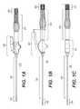
- FIG. 1Ais a perspective view of an articulated cavity creator representative of various embodiments disclosed herein;
- FIG. 1Bis a side view of the articulated cavity creator of FIG. 1A ;
- FIG. 1Cis a bottom view of the articulated cavity creator of FIGS. 1A and 1B ;
- FIG. 1Dis a exploded perspective view of the articulated cavity creator of FIGS. 1A , 1 B, and 1 C;
- FIG. 2Ais an exploded perspective view of an exemplary tip assembly comprising the distal end of an articulated cavity creator representative of several embodiments disclosed herein;
- FIG. 2Bis a side view of the exemplary tip assembly of FIG. 2A in a curved configuration
- FIG. 3Ais a perspective view of a cavity creator tip representative of various embodiments disclosed herein;
- FIG. 3Bis a cross-sectional top view of the cavity creator tip of FIG. 3A ;
- FIG. 3Cis a side view of the cavity creator tip of FIGS. 3A and 3B ;
- FIG. 3Dis a proximal end view of the cavity creator tip of FIGS. 3A , 3 B, and 3 C;
- FIG. 4Ais a perspective view of a cavity creator curving element representative of various embodiments disclosed herein;
- FIG. 4Bis a distal end view of the cavity creator curving element of FIG. 4A ;
- FIG. 5Ais a perspective view of a cavity creator shaft coupler representative of various embodiments disclosed herein;
- FIG. 5Bis a side view of the cavity creator shaft coupler of FIG. 5A ;
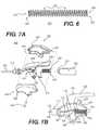
- FIG. 6is a side view of a cavity creator coil enclosure representative of various embodiments disclosed herein;
- FIG. 7Ais an exploded perspective view of an exemplary lever assembly of an articulated cavity creator representative of several embodiments disclosed herein;
- FIG. 7Bis an exposed side view of the exemplary lever assembly of FIG. 7A ;
- FIG. 8Ais side view of an exemplary rotation shaft of an articulated cavity creator representative of several embodiments disclosed herein;
- FIG. 8Bis a cross-sectional view of the exemplary rotation shaft of FIG. 8A ;
- FIG. 9is an exploded perspective view of an exemplary tensioner assembly comprising the proximal end of an articulated cavity creator representative of several embodiments disclosed herein;
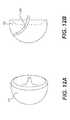
- FIG. 10Ais a perspective view of a cavity creator tensioner representative of various embodiments disclosed herein;
- FIG. 10Bis a cross-sectional top view of the cavity creator tensioner of FIG. 10A ;
- FIG. 10Cis a partially-cross-sectional side view of the cavity creator tensioner of FIGS. 10A and 10B ;
- FIG. 10Dis a distal end view of the cavity creator tensioner of FIGS. 10A , 10 B, and 10 C;
- FIG. 11Ais a perspective view of a cavity creator tension knob representative of various embodiments disclosed herein;
- FIG. 11Bis a side view of the cavity creator tension knob of FIG. 11A ;
- FIG. 11Cis a cross-sectional side view of the cavity creator tension knob of FIGS. 11A and 11B ;
- FIG. 11Dis a proximal end view of the cavity creator tension knob of FIGS. 11A , 11 B, and 11 C;
- FIG. 12Ais a perspective view of a maximum cavity creatable utilizing certain embodiments of the cavity creator disclosed herein;
- FIG. 12Bis a side view of the maximum cavity of FIG. 12A further including the tip assembly of FIG. 2 in position within the interior body;
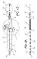
- FIG. 12Cis an operational flow diagram illustrating a method for creating the cavity illustrated in FIGS. 12A and 12B utilizing certain embodiments of the cavity creator disclosed herein.
- various componentsmay be described herein as extending horizontally along a longitudinal direction “L” and lateral direction “A”, and vertically along a transverse direction “T”.
- the terms “lateral”, “longitudinal”, and “transverse”are used to describe the orthogonal directional components of various items. It should be appreciated that while the longitudinal and lateral directions are illustrated as extending along a horizontal plane, and that the transverse direction is illustrated as extending along a vertical plane, the planes that encompass the various directions may differ during use. Accordingly, the directional terms “vertical” and “horizontal” are used to describe the components merely for the purposes of clarity and illustration and are not meant to be limiting.
- FIG. 1Ais a perspective view of an articulated cavity creator 100 representative of various embodiments disclosed herein.
- FIG. 1Bis a side view of the articulated cavity creator 100 of FIG. 1A .
- FIG. 1Cis a bottom view of the articulated cavity creator 100 of FIGS. 1A and 1B .
- FIG. 1Dis a exploded perspective view of the articulated cavity creator 100 of FIGS. 1A , 1 B, and 1 C.
- an articulated cavity creatormay comprise a tip assembly 200 , an intra-catheter shaft 300 , a lever assembly 400 , a rotation shaft 500 , and a tensioner assembly 600 , each operatively coupled in order from distal end to proximal end of the ACC as shown in FIG. 1 .
- the ACCfurther comprises an off-center cable 120 and a midline cable 140 .
- the off-center cable 120is fixedly coupled to the lever assembly 400 at its proximal end, passes longitudinally through the intra-catheter shaft 300 , and is fixedly coupled to the tip assembly 200 at its distal end.
- the midline cable 140in contrast, is effectively doubled-backed on itself with both ends 142 and 144 fixedly coupled to the tip assembly 200 and passing longitudinally through the intra-catheter shaft 300 , the lever assembly 400 , the rotation shaft 500 , and operationally coupling a rotational component 602 of the tensioner assembly 600 at its bend 146 .
- both ends 142 and 144fixedly coupled to the tip assembly 200 and passing longitudinally through the intra-catheter shaft 300 , the lever assembly 400 , the rotation shaft 500 , and operationally coupling a rotational component 602 of the tensioner assembly 600 at its bend 146 .
- FIG. 2Ais an exploded perspective view of an exemplary tip assembly 200 comprising the distal end of an articulated cavity creator 100 representative of several embodiments disclosed herein.
- FIG. 2Bis a side view of the exemplary tip assembly 200 of FIG. 2A in a curved configuration.
- the tip assembly 200may comprise a cavity creator tip 210 , a plurality of interconnecting curving elements 230 , a coil enclosure 250 , and shaft coupler 260 for coupling to the intra-catheter shaft 300 . As shown in FIG. 2 ,
- the proximal end 212 of the tip 210 , the curving elements 230 , and the distal end 264 of the shaft coupler 260are movably coupled and enclosed within the hollow created by the coil enclosure 250 , thereby exposing the distal end 214 of the tip 210 beyond the distal end 254 of the coil enclosure 250 , as well as exposing the proximal end 262 of the shaft coupler 260 beyond the proximal end 252 of the coil enclosure 250 .
- the coil enclosure 250may be replaced with other enclosures such as a sheath or a series of rings, for example, and that such alternative enclosures may be constructed of any of several suitable materials, including but not limited to rubber, latex, plastic or nitinol.
- FIG. 2BFurther shown in FIG. 2B is the distal end of the doubled-back midline cable 140 running on both sides of the tip assembly 200 (one strand shown, the other strand behind and obstructed from view), both ends of which are fixedly coupled to the tip 210 and run down concurrent lateral channels (highlighted in other illustrations) on each side of the tip 210 , the curving elements 230 , and the shaft coupler 260 , and thereby pass through the hollow of the coil enclosure 250 and through the intra-catheter shaft 300 .
- This midline cable 140provides the tension necessary to hold the tip 210 , the curving elements 230 , and the shaft coupler 260 movably coupled and enclosed within the hollow created by the coil enclosure 250 .
- the distal end of the off-center cable 120fixedly coupled to the tip 210 and running down a top channel (highlighted in other illustrations) of the tip 210 , the curving elements 230 , and the shaft coupler 260 , and thereby passing through the hollow of the coil enclosure 250 and the intra-catheter shaft 300 .
- This off-center cable 120provides variable tension on the top side of the tip assembly 200 causing the tip 210 , the curving elements 230 , and the shaft coupler 260 to together movably curve against the coil enclosure 250 (as shown) in various curved configurations depending on the amount of variable tension applied by the off-center cable 120 .
- the curving elements 230 within tip assembly 200cooperate to approximate a curved shape.
- the tip assembly 200may form such a curved shape around any object that the tip assembly 200 encounters as the off-center cable 120 is tensed along the top side of the tip assembly 200 .
- the aforementioned curvable motions and restrictions of the tip assembly 200are further complimented by the shaping of the proximal end 212 of the tip 210 , both ends of the curving elements 230 , and the distal end 264 of the shaft coupler 260 , which help assist curving of the tip assembly 200 in a vertical direction and help prevent curving in a horizontal direction.
- This shapingis discussed in greater detail later herein.
- FIG. 3Ais a perspective view of a cavity creator tip 210 representative of various embodiments disclosed herein.
- FIG. 3Bis a cross-sectional top view of the cavity creator tip 210 of FIG. 3A .
- FIG. 3Cis a side view of the cavity creator tip 210 of FIGS. 3A and 3B .
- FIG. 3Dis a proximal end view of the cavity creator tip 210 of FIGS. 3A , 3 B, and 3 C.
- the cavity creator tip 210(or simply “tip”) comprises a partial curving element 222 corresponding to the proximal end 212 and a head 224 corresponding to the distal end 214 .
- the partial curving element 222further comprises two lateral channels 216 , one oriented to each side of the tip 210 , as well as a top channel 220 oriented to the top of the tip 210 .
- These channels 216 and 220proceed through the head 224 to open at the distal end of the tip 210 as shown in the illustrations, and for certain embodiments these distal endpoints for the channels 216 and 220 at the head 224 may comprise fastening or welding points for fixedly coupling the both ends 142 of the doubled-back midline cable 140 , as well as the distal end of the off-center cable 120 , to the tip 210 .
- the head 224may also comprise a distal edge 226 that is vertically flat (as shown) or, in other embodiments, may be formed to provide a rounded edge or an edge of some other form or shape.
- the headalso comprises a stop surface 228 for engaging but not passing into the distal end of the coil enclosure 250 .
- the partial curving element 222insertable into the distal end of the coil enclosure 250 , further comprises a partially-cylindrical convex proximal male end 202 for operatively coupling to a corresponding partially-cylindrical distal female end of a curving element 230 to facilitate curving of the tip assembly 200 in a vertical direction and help prevent curving in a horizontal direction (the partially-cylindrical shape being curved in the vertical direction but flat in the horizontal direction).
- the two lateral channels 216each comprise a slope surface 218 to allow curving of a tip assembly 200 in a vertical “up” direction (but not in a vertical “down” direction) against each strand of the midline cable 140 running through said lateral channels 216 .
- FIG. 4Ais a perspective view of a cavity creator curving element 230 representative of various embodiments disclosed herein.
- FIG. 4Bis a distal end view of the cavity creator curving element 230 of FIG. 4A .
- each such curving element 230comprises two lateral channels 216 , one oriented to each side of the curving element 230 , as well as a top channel 220 oriented to the top of the curving element 230 .
- the curving element 222further comprises a partially-cylindrical convex proximal male end 202 and a partially-cylindrical concave proximal female end 204 .
- the proximal male end 202is shaped to operatively couple with the corresponding distal female end 204 of either another curving element 230 or shaft coupler 260 .
- the distal female end 204is shaped to operatively couple with the corresponding proximal male end 202 of either another curving element 230 or the distal end 212 of the tip 210 accordingly.
- Both the proximal male end 202 and the distal female end 204 of the curving element 230facilitate curving of the tip assembly 200 in a vertical direction and help prevent curving in a horizontal direction (the partially-cylindrical shape being curved in the vertical direction but flat in the horizontal direction).
- the two lateral channels 216each comprise a slope surface 218 to allow curving of a tip assembly 200 in a vertical “up” direction (but not in a vertical “down” direction) against each strand of the midline cable 140 running through said lateral channels 216 .
- FIG. 5Ais a perspective view of a cavity creator shaft coupler 260 representative of various embodiments disclosed herein.
- FIG. 5Bis a side view of the cavity creator shaft coupler 260 of FIG. 5A .
- the shaft coupler 260comprises a partial curving element 222 ′ corresponding to the distal end 262 , a collar 266 centrally located, and an insertion component 268 corresponding to the proximal end 264 .
- the shaft coupler 260further comprises two lateral channels 216 , one oriented to each side of the shaft coupler 260 , as well as a top channel 220 oriented to the top of the shaft coupler 260 , where all three channels run from the proximal end 262 to the distal end 264 of the shaft coupler 260 .
- the partial curving element 222 ′insertable into the proximal end of the coil enclosure 250 , further comprises a partially-cylindrical concave distal female end 204 for operatively coupling to a corresponding partially-cylindrical proximal male end 202 of a curving element 230 to facilitate curving of the tip assembly 200 in a vertical direction and help prevent curving in a horizontal direction (the partially-cylindrical shape being curved in the vertical direction but flat in the horizontal direction).
- the collar 266comprises a first stop surface 272 for engaging but not passing into the distal end of the intra-catheter shaft 300 , as well as a second stop surface 274 for engaging but not passing into the proximal end of the coil enclosure 250 .
- the insertion component 268is insertable into the distal end of the intra-catheter shaft 300 and, for certain embodiments, may be fastening or welded to said intra-catheter shaft 300 .
- FIG. 6is a side view of a cavity creator coil enclosure 250 representative of various embodiments disclosed herein.
- the coil enclosure 250is both compressible relative to the longitudinal direction as shown, as well as curvable relative from the longitudinal direction as shown.
- the proximal end 252 of the coil enclosure 250operatively couples with the second stop surface 274 of the shaft coupler 260
- the distal end 254 of the coil enclosure 250operatively couples with the stop surface 228 of the tip 210 .
- the helical body 258 of the coil enclosure 250forms a hollow 256 extending from the distal end 254 to the proximal end 252 of the coil enclosure 250 and effectively encloses the proximal end 212 of the tip 210 , the plurality of interconnecting curving elements 230 , and the distal end 264 of the shaft coupler 260 that comprise the tip assembly 200 .
- the tip assembly 200couples to the distal end of the intra-catheter shaft 300 , and the midline cable 140 and the off-center cable 120 fixedly coupled to the tip 210 pass through the tip assembly 200 and through the intra-catheter shaft 300 to the lever assembly 400 in the case of the off-center cable 120 , and through the lever assembly 400 and the rotation shaft 500 to the tensioner assembly 600 in the case of both strands of the midline cable 140 .
- FIG. 7Ais an exploded perspective view of an exemplary lever assembly 400 of an articulated cavity creator 100 representative of several embodiments disclosed herein.
- FIG. 7Bis an exposed side view of the exemplary lever assembly 400 of FIG. 7A (with the left body 422 of the lever pivot 420 removed).
- the lever assembly 400comprises a receiver 410 , a lever pivot 420 (comprising a left body 422 and a right body 424 ) a lever 430 , and a lever spring 440 . Also shown for reference are the proximal end of the intra-catheter shaft 300 and the distal end of the rotation shaft 500 .
- the distal end of the receiver 410is coupled to the intra-catheter shaft 300 , while the proximal end of the receiver 410 is coupled to the distal end 448 of the lever pivot 420 .
- the lever pivot 420is also movably coupled to the lever 430 via a pivot pin 428 where the pivot pin 428 is coupled at each end to the left body 422 and right body 424 of the lever pivot 420 and passes through the pivot channel 432 of the lever 430 to couple with the lever 430 .
- pivot pin 428may be fixedly coupled to the lever pivot 420 , the lever 430 , or neither (i.e., movably coupled to both).
- the lever spring 440comprises a proximal end 442 operatively coupled to a boss 501 of the rotation shaft 500 , and a distal end 444 operatively coupled to a proximal surface 434 of the lever 430 .
- the midline cable 140(one strand visible and the other strand obscured behind the visible strand) passes through the receiver 410 , the lever 430 , and the lever spring 440 .
- the off-center cable 120passes through the receiver 410 and is fixedly connected to the lever 430 .
- the off-center cable 120may be fixedly attached to a threaded coupling rod 122 that then screws through a channel 438 in the lever 430 and is affixed in position with a washer and nut combination 124 .
- the lever spring 440exerts pressure against the lever 430 to maintain the lever 430 in a longitudinally forward position (in the distal direction) which, in turn, keeps the tip assembly 200 in an uncurved orientation.
- pressure applied to the pressure surface 436 of the lever 430causes the lever to pivot longitudinally backward (in the proximal direction) which, in turn, causes the tip assembly 200 to curve about an axis. (The motion of the tip assembly 200 thus carves a narrow path through, for example, cancellous bone.)
- FIG. 8Ais side view of an exemplary rotation shaft 500 of an articulated cavity creator 100 representative of several embodiments disclosed herein.
- FIG. 8Bis a cross-sectional view of the exemplary rotation shaft 500 of FIG. 8A .
- the rotation shaft 500comprises a proximal end 502 for operationally coupling to a tensioner assembly 600 as well as a distal end 504 (e.g., a groove) for fixedly coupling to a lever assembly 400 .
- the rotation shaft 500also comprises a central channel 510 through which the midline cable 140 passes.
- the proximal end 502further comprises two coupling slots 512 to movably couple the tensioner (not shown) of the tensioner assembly 600 (described in more detail below).
- the rotation shaft 500enables an operator (such as a surgeon) to rotate (or “twist”) the entire articulated cavity creator 100 and, in turn, rotate (or “spin”) the tip assembly 200 in a manner that, coupled with the variable curving ability provided by the lever assembly 400 , carves out a cavity within, for example, cancellous bone.
- FIG. 9is an exploded perspective view of an exemplary tensioner assembly 600 comprising the proximal end of an articulated cavity creator 100 representative of several embodiments disclosed herein.
- the tensioner assembly 600comprises a tensioner 620 , a midline pin 640 , and a tension knob 650 .
- the proximal end 502 of the rotation shaft 500said proximal end comprising the two coupling slots 512 to movably couple the tensioner 620 .
- FIG. 10Ais a perspective view of a cavity creator tensioner 620 representative of various embodiments disclosed herein.
- FIG. 10Bis a cross-sectional top view of the cavity creator tensioner 620 of FIG. 10A .
- FIG. 10Cis a partially-cross-sectional side view of the cavity creator tensioner of FIGS. 10A and 10B .
- FIG. 10Dis a distal end view of the cavity creator tensioner of FIGS. 10A , 10 B, and 10 C.
- the tensioner 620comprises a tension head 622 fixedly coupled to a threaded shaft 632 for engaging the tension knob 650 .
- the tension head 622further comprises a pin hole 624 , a cable return cavity 626 , and two slotting edges 628 .
- the two slotting edges 628slidably engage the two coupling slots 512 of the rotation shaft 500 , thus preventing rotation of the tensioner 620 within the rotation shaft 500 while also ensuring that the tensioner perfectly rotates along with the rotation shaft 500 when it is rotated.
- the proximal end of the doubled-back midline cable 140is inserted into cable return cavity 626 and the midline pin 640 is introduced through the pin hole 624 to hold the midline cable 140 in place (as shown in FIG. 10D ).
- the midline cable 140being movable along the proximal rounded surface of the midline pin 640 , provides even tension throughout the entire device to the tip assembly 200 .
- FIG. 11Ais a perspective view of a cavity creator tension knob 650 representative of various embodiments disclosed herein.
- FIG. 11Bis a side view of the cavity creator tension knob 650 of FIG. 11A .
- FIG. 11Cis a cross-sectional side view of the cavity creator tension knob 650 of FIGS. 11A and 11B .
- FIG. 11Dis a proximal end view of the cavity creator tension knob 650 of FIGS. 11A , 11 B, and 11 C.
- the tension knob 650comprises a twist body 652 having a proximal end 654 and a distal end 656 and a threaded hole 658 running from the proximal end 654 to the distal end 656 .
- the distal end 656abuts against the proximal end 502 of the rotation shaft 500 but is still able to rotate.
- the threaded hole 658engages the threaded shaft 632 of the tensioner 620 enabling the tension knob 650 to draw the tensioner 620 back in a proximal direction by rotably turning the tension knob 650 in one direction (e.g.
- FIG. 12Ais a perspective view of a maximum cavity 702 creatable utilizing certain embodiments of the articulated cavity creator 100 disclosed herein.
- FIG. 12Bis a side view of the maximum cavity of FIG. 12A further including the tip assembly 200 of FIG. 2 in position within the interior body.
- FIG. 12Cis an operational flow diagram illustrating a method 740 for creating the cavity illustrated in FIGS. 12A and 12B utilizing certain embodiments of the cavity creator disclosed herein.
- the method 740comprises, at 742 , inserting a catheter into a target location such as an interior body (e.g., a region of cancellous bone).
- a target locationsuch as an interior body (e.g., a region of cancellous bone).
- inserting the articulated cavity creator 100 through the cathetersuch that the tip assembly 100 extends beyond the distal end of the catheter and into the target region.
- the tip assembly 200is curved and straightened by action of the lever 430 in combination with the articulated cavity creator 100 being rotated via the rotation shaft 500 .
- the tip assembly 100might be incrementally curved through its range of motion (from straight to maximally curved), moving the tip 210 no more than its width with each increment, and at each increment rotating the rotation shaft 500 at least a full 360-degrees.
- the rotation shaftmight be rotated incrementally through a full rotation (360-degrees), rotating the tip 210 with each increment no more than the tip's 210 width in each increment position (such as when curved perpendicular to the intra-catheter shaft 300 ), and at each increment engaging the lever 430 to move the tip assembly 200 through its full range of motion from straight to maximally curved and back.
- the articulated cavity creator 100is removed.
- the rotation and curving of the device to form a cavitycan be performed manually by a surgeon who rotates the device via the rotation shaft and also curves the device by action of the lever assembly.
- the rotation and/or the curving of the tip assemblycan be performed by motorized components that may utilize, in certain implementations, microprocessors or other guidance systems to coordinate the rotation and curving motions to optimally form the cavity within the target body.
- the various components described hereincan be formed from a variety of biocompatible materials, such as cobalt chromium molybdenum (CoCrMo), titanium and titanium alloys, stainless steel or other metals, as well as ceramics or polymers.
- a coatingmay be added or applied to the various components described herein to improve physical or chemical properties, such as a plasma-sprayed titanium coating or Hydroxypatite.
- skilled artisanswill also appreciate that the various components herein described can be constructed with any dimensions desirable for implantation and cavity creation.
- the various embodiments disclosed hereinmay be adapted for use in virtually any interior body region where the formation of a cavity within tissue is required for a therapeutic or diagnostic purpose. While several embodiments are herein described with regard to treating bones, other embodiments can be used in other interior body regions as well. In addition, it is also anticipated that certain embodiments could be used for purposes other than medical, such as construction, manufacturing, and excavation, among others; accordingly, nothing herein is intended to limit application of the various embodiments to purely medical uses.
Landscapes
- Health & Medical Sciences (AREA)
- Surgery (AREA)
- Life Sciences & Earth Sciences (AREA)
- Biomedical Technology (AREA)
- Medical Informatics (AREA)
- Orthopedic Medicine & Surgery (AREA)
- Oral & Maxillofacial Surgery (AREA)
- Engineering & Computer Science (AREA)
- Dentistry (AREA)
- Heart & Thoracic Surgery (AREA)
- Nuclear Medicine, Radiotherapy & Molecular Imaging (AREA)
- Molecular Biology (AREA)
- Animal Behavior & Ethology (AREA)
- General Health & Medical Sciences (AREA)
- Public Health (AREA)
- Veterinary Medicine (AREA)
- Surgical Instruments (AREA)
Abstract
Description
Claims (15)
Priority Applications (2)
| Application Number | Priority Date | Filing Date | Title |
|---|---|---|---|
| US13/205,826US9119639B2 (en) | 2011-08-09 | 2011-08-09 | Articulated cavity creator |
| US14/841,285US9610083B2 (en) | 2011-08-09 | 2015-08-31 | Articulated cavity creator |
Applications Claiming Priority (1)
| Application Number | Priority Date | Filing Date | Title |
|---|---|---|---|
| US13/205,826US9119639B2 (en) | 2011-08-09 | 2011-08-09 | Articulated cavity creator |
Related Child Applications (1)
| Application Number | Title | Priority Date | Filing Date |
|---|---|---|---|
| US14/841,285ContinuationUS9610083B2 (en) | 2011-08-09 | 2015-08-31 | Articulated cavity creator |
Publications (2)
| Publication Number | Publication Date |
|---|---|
| US20130041377A1 US20130041377A1 (en) | 2013-02-14 |
| US9119639B2true US9119639B2 (en) | 2015-09-01 |
Family
ID=47677998
Family Applications (2)
| Application Number | Title | Priority Date | Filing Date |
|---|---|---|---|
| US13/205,826Active2031-10-09US9119639B2 (en) | 2011-08-09 | 2011-08-09 | Articulated cavity creator |
| US14/841,285ActiveUS9610083B2 (en) | 2011-08-09 | 2015-08-31 | Articulated cavity creator |
Family Applications After (1)
| Application Number | Title | Priority Date | Filing Date |
|---|---|---|---|
| US14/841,285ActiveUS9610083B2 (en) | 2011-08-09 | 2015-08-31 | Articulated cavity creator |
Country Status (1)
| Country | Link |
|---|---|
| US (2) | US9119639B2 (en) |
Cited By (19)
| Publication number | Priority date | Publication date | Assignee | Title |
|---|---|---|---|---|
| US20150190149A1 (en)* | 2014-01-09 | 2015-07-09 | Zyga Technology, Inc. | Undercutting system for use in conjunction with sacroiliac fusion |
| US9439693B2 (en) | 2013-02-01 | 2016-09-13 | DePuy Synthes Products, Inc. | Steerable needle assembly for use in vertebral body augmentation |
| US9610083B2 (en)* | 2011-08-09 | 2017-04-04 | DePuy Synthes Products, Inc. | Articulated cavity creator |
| US10596002B2 (en) | 2010-01-04 | 2020-03-24 | Rti Surgical, Inc. | Sacroiliac fusion system |
| US10695073B2 (en) | 2017-08-22 | 2020-06-30 | Arthrex, Inc. | Control system for retrograde drill medical device |
| US10905440B2 (en) | 2008-09-26 | 2021-02-02 | Relievant Medsystems, Inc. | Nerve modulation systems |
| US11007010B2 (en) | 2019-09-12 | 2021-05-18 | Relevant Medsysterns, Inc. | Curved bone access systems |
| US11065046B2 (en) | 2013-08-08 | 2021-07-20 | Relievant Medsystems, Inc. | Modulating nerves within bone |
| US11160563B2 (en) | 2012-11-05 | 2021-11-02 | Relievant Medsystems, Inc. | Systems for navigation and treatment within a vertebral body |
| US20220110639A1 (en)* | 2013-10-15 | 2022-04-14 | Stryker Corporation | Device including steering cables for creating a cavity or a channel in bone |
| US11331108B2 (en)* | 2017-10-27 | 2022-05-17 | Joimax Gmbh | Medical device |
| US11471210B2 (en) | 2011-12-30 | 2022-10-18 | Relievant Medsystems, Inc. | Methods of denervating vertebral body using external energy source |
| US11596468B2 (en) | 2002-09-30 | 2023-03-07 | Relievant Medsystems, Inc. | Intraosseous nerve treatment |
| US11690667B2 (en) | 2012-09-12 | 2023-07-04 | Relievant Medsystems, Inc. | Radiofrequency ablation of tissue within a vertebral body |
| US12039731B2 (en) | 2020-12-22 | 2024-07-16 | Relievant Medsystems, Inc. | Prediction of candidates for spinal neuromodulation |
| US12082876B1 (en) | 2020-09-28 | 2024-09-10 | Relievant Medsystems, Inc. | Introducer drill |
| US12279799B2 (en) | 2019-04-24 | 2025-04-22 | Stryker Corporation | Systems and methods for off-axis treatment of a vertebral body |
| US12303166B2 (en) | 2008-09-26 | 2025-05-20 | Relievant Medsystems, Inc. | Methods for accessing nerves within bone |
| US12433668B1 (en) | 2021-11-08 | 2025-10-07 | Relievant Medsystems, Inc. | Impedance stoppage mitigation during radiofrequency tissue ablation procedures |
Families Citing this family (19)
| Publication number | Priority date | Publication date | Assignee | Title |
|---|---|---|---|---|
| US20100298832A1 (en) | 2009-05-20 | 2010-11-25 | Osseon Therapeutics, Inc. | Steerable curvable vertebroplasty drill |
| US9125671B2 (en) | 2010-04-29 | 2015-09-08 | Dfine, Inc. | System for use in treatment of vertebral fractures |
| CN103315797B (en)* | 2013-06-14 | 2015-04-08 | 上海市第六人民医院 | Reamer for preventing looseness of bone cement artificial joint prosthesis stem |
| US9937323B2 (en)* | 2014-02-28 | 2018-04-10 | Cook Medical Technologies Llc | Deflectable catheters, systems, and methods for the visualization and treatment of bodily passages |
| USD868253S1 (en) | 2014-10-13 | 2019-11-26 | Boston Scientific Scimed, Inc. | Macerator wire |
| US10219810B2 (en)* | 2015-02-16 | 2019-03-05 | Warsaw Orthopedic, Inc. | Surgical instrument system and method |
| GB201504854D0 (en)* | 2015-03-23 | 2015-05-06 | Depuy Ireland | A attachment mechanism for a surgical instrument component |
| US9901392B2 (en) | 2015-05-11 | 2018-02-27 | Dfine, Inc. | System for use in treatment of vertebral fractures |
| WO2016204711A1 (en)* | 2015-06-16 | 2016-12-22 | Spine Wave, Inc. | Instrument and system for placing graft, implant and graft material for minimally invasive posterolateral fusion |
| JP2019534130A (en) | 2016-10-27 | 2019-11-28 | ディーファイン,インコーポレイティド | Articulated osteotome with cement delivery channel |
| CA3041114A1 (en) | 2016-11-28 | 2018-05-31 | Dfine, Inc. | Tumor ablation devices and related methods |
| US10470781B2 (en) | 2016-12-09 | 2019-11-12 | Dfine, Inc. | Medical devices for treating hard tissues and related methods |
| US10660656B2 (en) | 2017-01-06 | 2020-05-26 | Dfine, Inc. | Osteotome with a distal portion for simultaneous advancement and articulation |
| US11571305B2 (en) | 2017-07-24 | 2023-02-07 | Emory University | Cardiac valve leaflet enhancer devices and systems |
| US11937864B2 (en) | 2018-11-08 | 2024-03-26 | Dfine, Inc. | Ablation systems with parameter-based modulation and related devices and methods |
| US11986229B2 (en) | 2019-09-18 | 2024-05-21 | Merit Medical Systems, Inc. | Osteotome with inflatable portion and multiwire articulation |
| CN111202549B (en)* | 2020-01-16 | 2022-02-15 | 南京佗道医疗科技有限公司 | Spinal implantation channel instrument |
| US12433749B2 (en) | 2023-08-25 | 2025-10-07 | Emory University | Systems, devices, and methods for reducing heart valve regurgitation |
| US12396855B1 (en) | 2024-07-25 | 2025-08-26 | Nyra Medical, Inc. | Systems, devices, and methods for reducing heart valve regurgitation |
Citations (123)
| Publication number | Priority date | Publication date | Assignee | Title |
|---|---|---|---|---|
| US3223083A (en) | 1960-09-09 | 1965-12-14 | President And Directors Of Geo | Method for adhesively securing together skin and other soft tissue and bone |
| US3503385A (en) | 1965-09-27 | 1970-03-31 | Cordis Corp | Guidable catheter assembly and manipulator therefor |
| US4405249A (en) | 1980-03-28 | 1983-09-20 | National Research Development Corporation | Dispensing apparatus and method |
| US4627434A (en) | 1985-05-03 | 1986-12-09 | Murray William M | Bone cement system and method |
| US4630616A (en) | 1984-06-15 | 1986-12-23 | Berkley And Company, Inc. | Bone marrow needle |
| US4653489A (en) | 1984-04-02 | 1987-03-31 | Tronzo Raymond G | Fenestrated hip screw and method of augmented fixation |
| US4969888A (en) | 1989-02-09 | 1990-11-13 | Arie Scholten | Surgical protocol for fixation of osteoporotic bone using inflatable device |
| US4998923A (en) | 1988-08-11 | 1991-03-12 | Advanced Cardiovascular Systems, Inc. | Steerable dilatation catheter |
| US5002543A (en) | 1990-04-09 | 1991-03-26 | Bradshaw Anthony J | Steerable intramedullary fracture reduction device |
| US5030201A (en) | 1989-11-24 | 1991-07-09 | Aubrey Palestrant | Expandable atherectomy catheter device |
| US5231989A (en) | 1991-02-15 | 1993-08-03 | Raychem Corporation | Steerable cannula |
| US5284128A (en) | 1992-01-24 | 1994-02-08 | Applied Medical Resources Corporation | Surgical manipulator |
| US5438975A (en)* | 1993-03-24 | 1995-08-08 | Machida Endoscope Co., Ltd. | Distal tip of endoscope having spirally coiled control wires |
| US5509923A (en) | 1989-08-16 | 1996-04-23 | Raychem Corporation | Device for dissecting, grasping, or cutting an object |
| US5512037A (en) | 1994-05-12 | 1996-04-30 | United States Surgical Corporation | Percutaneous surgical retractor |
| WO1996013297A1 (en) | 1994-10-28 | 1996-05-09 | Intelliwire, Inc. | Low profile balloon-on-a-wire catheter with shapable and/or deflectable tip and method |
| WO1996020752A1 (en) | 1995-01-04 | 1996-07-11 | Advanced Cardiovascular Systems, Inc. | Catheter shaft with an oblong transverse cross section |
| US5545200A (en) | 1993-07-20 | 1996-08-13 | Medtronic Cardiorhythm | Steerable electrophysiology catheter |
| US5709697A (en) | 1995-11-22 | 1998-01-20 | United States Surgical Corporation | Apparatus and method for removing tissue |
| US5749879A (en) | 1989-08-16 | 1998-05-12 | Medtronic, Inc. | Device or apparatus for manipulating matter |
| US5755731A (en) | 1994-04-15 | 1998-05-26 | Smith & Nephew Dyonics, Inc. | Curved surgical instrument with segmented inner member |
| WO1998056299A1 (en) | 1997-06-11 | 1998-12-17 | Endius Incorporated | Surgical instrument |
| US5851208A (en)* | 1996-10-15 | 1998-12-22 | Linvatec Corporation | Rotatable surgical burr |
| US5860995A (en) | 1995-09-22 | 1999-01-19 | Misener Medical Co. Inc. | Laparoscopic endoscopic surgical instrument |
| WO1998017190A8 (en) | 1996-10-23 | 1999-04-22 | Oratec Interventions Inc | Method and apparatus for treating intervertebral discs |
| US5904690A (en) | 1989-08-16 | 1999-05-18 | Medtronic, Inc. | Device or apparatus for manipulating matter |
| WO1999049819A1 (en) | 1998-04-01 | 1999-10-07 | Parallax Medical, Inc. | Pressure applicator for hard tissue implant placement |
| US5972015A (en) | 1997-08-15 | 1999-10-26 | Kyphon Inc. | Expandable, asymetric structures for deployment in interior body regions |
| US5987344A (en) | 1996-08-08 | 1999-11-16 | Medtronic, Inc. | Handle for catheter assembly with multifunction wire |
| US6019776A (en) | 1997-10-14 | 2000-02-01 | Parallax Medical, Inc. | Precision depth guided instruments for use in vertebroplasty |
| US6033411A (en) | 1997-10-14 | 2000-03-07 | Parallax Medical Inc. | Precision depth guided instruments for use in vertebroplasty |
| US6048339A (en) | 1998-06-29 | 2000-04-11 | Endius Incorporated | Flexible surgical instruments with suction |
| US6048346A (en) | 1997-08-13 | 2000-04-11 | Kyphon Inc. | Systems and methods for injecting flowable materials into bones |
| US6053922A (en) | 1995-07-18 | 2000-04-25 | Krause; William R. | Flexible shaft |
| WO2000033909A1 (en) | 1998-12-09 | 2000-06-15 | Cook Incorporated | Hollow, curved, superelastic medical needle |
| US6099514A (en) | 1996-08-13 | 2000-08-08 | Oratec Interventions, Inc. | Method and apparatus for delivering or removing material from the interior of an intervertebral disc |
| US6217581B1 (en) | 1995-10-18 | 2001-04-17 | John Thomas Tolson | High pressure cement injection device for bone repair |
| US6241734B1 (en) | 1998-08-14 | 2001-06-05 | Kyphon, Inc. | Systems and methods for placing materials into bone |
| US6248110B1 (en) | 1994-01-26 | 2001-06-19 | Kyphon, Inc. | Systems and methods for treating fractured or diseased bone using expandable bodies |
| US6337142B2 (en) | 1997-07-02 | 2002-01-08 | Stryker Trauma Gmbh | Elongate element for transmitting forces |
| WO2002003870A1 (en) | 2000-07-12 | 2002-01-17 | Spine Next | Curettage instrument |
| US6348055B1 (en) | 1999-03-24 | 2002-02-19 | Parallax Medical, Inc. | Non-compliant system for delivery of implant material |
| US20020026197A1 (en) | 2000-08-11 | 2002-02-28 | Foley Kevin T. | Surgical instrumentation and method for treatment of the spine |
| US6375659B1 (en) | 2001-02-20 | 2002-04-23 | Vita Licensing, Inc. | Method for delivery of biocompatible material |
| US6395007B1 (en) | 1999-03-16 | 2002-05-28 | American Osteomedix, Inc. | Apparatus and method for fixation of osteoporotic bone |
| US6402758B1 (en) | 2001-04-16 | 2002-06-11 | John Thomas Tolson | Methods for repairing bone using a high pressure cement injection |
| US6440138B1 (en) | 1998-04-06 | 2002-08-27 | Kyphon Inc. | Structures and methods for creating cavities in interior body regions |
| US20020151927A1 (en) | 2001-04-03 | 2002-10-17 | Nareak Douk | Temporary intraluminal filter guidewire and methods of use |
| US20020188300A1 (en) | 2001-06-06 | 2002-12-12 | Arramon Yves P. | Cannula system for hard tissue implant delivery |
| US20030004537A1 (en) | 2001-06-29 | 2003-01-02 | Boyle William J. | Delivery and recovery sheaths for medical devices |
| US6582446B1 (en) | 1999-05-06 | 2003-06-24 | J. Alexander Marchosky | Method and apparatus for percutaneous osteoplasty |
| US20030163085A1 (en) | 2002-01-16 | 2003-08-28 | Tanner Howard M. | Catheter hand-piece apparatus and method of using the same |
| US20030187449A1 (en) | 2002-03-29 | 2003-10-02 | Mccleary Larry G. | Medical instrument for milling a curved path in bone and procedure |
| US20030187445A1 (en) | 2000-04-04 | 2003-10-02 | Peter T. Keith | Devices and methods for annular repair of intervertebral discs |
| US20030191474A1 (en) | 2000-02-16 | 2003-10-09 | Cragg Andrew H. | Apparatus for performing a discectomy through a trans-sacral axial bore within the vertebrae of the spine |
| US6641587B2 (en) | 1998-08-14 | 2003-11-04 | Kyphon Inc. | Systems and methods for treating vertebral bodies |
| US6645213B2 (en) | 1997-08-13 | 2003-11-11 | Kyphon Inc. | Systems and methods for injecting flowable materials into bones |
| US6676664B1 (en) | 1999-08-05 | 2004-01-13 | Grupo Grifols, S.A. | Device for metering hardenable mass for vertebroplastia and other similar bone treatments |
| US6679886B2 (en) | 2000-09-01 | 2004-01-20 | Synthes (Usa) | Tools and methods for creating cavities in bone |
| US20040024410A1 (en) | 2002-08-02 | 2004-02-05 | Scimed Life Systems, Inc. | Media delivery device for bone structures |
| US6716216B1 (en) | 1998-08-14 | 2004-04-06 | Kyphon Inc. | Systems and methods for treating vertebral bodies |
| US6726691B2 (en) | 1998-08-14 | 2004-04-27 | Kyphon Inc. | Methods for treating fractured and/or diseased bone |
| US6730095B2 (en) | 2002-06-26 | 2004-05-04 | Scimed Life Systems, Inc. | Retrograde plunger delivery system |
| US6740093B2 (en) | 2000-02-28 | 2004-05-25 | Stephen Hochschuler | Method and apparatus for treating a vertebral body |
| US6746451B2 (en) | 2001-06-01 | 2004-06-08 | Lance M. Middleton | Tissue cavitation device and method |
| US6770079B2 (en) | 1999-03-16 | 2004-08-03 | American Osteomedix, Inc. | Apparatus and method for fixation of osteoporotic bone |
| US6783515B1 (en) | 1999-09-30 | 2004-08-31 | Arthrocare Corporation | High pressure delivery system |
| US20050070913A1 (en) | 2003-09-29 | 2005-03-31 | Milbocker Michael T. | Devices and methods for spine repair |
| US20050070912A1 (en) | 2003-09-29 | 2005-03-31 | John Voellmicke | Vertebroplasty device having a flexible plunger |
| US6875219B2 (en) | 2003-02-14 | 2005-04-05 | Yves P. Arramon | Bone access system |
| WO2005051212A1 (en) | 2003-11-18 | 2005-06-09 | Somatex Medical Technologies Gmbh | Injection pump |
| US6923813B2 (en) | 2003-09-03 | 2005-08-02 | Kyphon Inc. | Devices for creating voids in interior body regions and related methods |
| US20050228397A1 (en) | 1998-08-14 | 2005-10-13 | Malandain Hugues F | Cavity filling device |
| US20050272978A1 (en)* | 2004-06-08 | 2005-12-08 | Brunnen Rainer D | Bendable portion of an insertion tube of an endoscope and method of producing it |
| US20060100640A1 (en) | 2001-11-28 | 2006-05-11 | Aptus Endosystems, Inc. | Devices, system, and methods for guiding an operative tool into an interior body region |
| US20060116689A1 (en) | 2004-06-16 | 2006-06-01 | Sdgi Holdings, Inc. | Surgical instrumentation and method for treatment of a spinal structure |
| US20060116690A1 (en) | 2004-02-12 | 2006-06-01 | Pagano Paul J | Surgical instrumentation and method for treatment of a spinal structure |
| US7066942B2 (en) | 2002-10-03 | 2006-06-27 | Wright Medical Technology, Inc. | Bendable needle for delivering bone graft material and method of use |
| US20060142694A1 (en) | 2004-12-28 | 2006-06-29 | Bednarek Michael C | Bi-directional steerable catheter control handle |
| US20060167416A1 (en) | 2004-11-23 | 2006-07-27 | Mark Mathis | Steerable device for accessing a target site and methods |
| US7153306B2 (en) | 2000-10-25 | 2006-12-26 | Kyphon Inc. | Systems and methods for reducing fractured bone using a fracture reduction cannula |
| US20070043430A1 (en) | 2001-01-22 | 2007-02-22 | Stinson Jonathan S | Stent delivery system and method of manufacturing same |
| US20070118142A1 (en) | 2005-11-18 | 2007-05-24 | Krueger John A | Device, system and method for delivering a curable material into bone |
| US20070142842A1 (en) | 2005-11-18 | 2007-06-21 | Krueger John A | Device, system and method for delivering a curable material into bone |
| US20070179340A1 (en) | 2005-12-20 | 2007-08-02 | Medicept, Inc. | Method and devices for minimally invasive arthroscopic procedures |
| US7264622B2 (en) | 1993-06-10 | 2007-09-04 | Warsaw Orthopedic, Inc. | System for radial bone displacement |
| WO2007036815A3 (en) | 2005-09-28 | 2007-09-13 | Disc O Tech Medical Tech Ltd | Cannula for injecting material into bone |
| WO2007147591A1 (en) | 2006-06-22 | 2007-12-27 | Roche Diagnostics Gmbh | Flexible device for introducing a medical apparatus into the body |
| WO2008011262A2 (en) | 2006-07-21 | 2008-01-24 | Bassem Georgy | Device and method for introducing flowable material into a body cavity |
| US20080086142A1 (en) | 2006-10-06 | 2008-04-10 | Kohm Andrew C | Products and Methods for Delivery of Material to Bone and Other Internal Body Parts |
| US20080091170A1 (en)* | 2003-09-12 | 2008-04-17 | Vargas Jaime S | Cannula system for free-space navigation and method of use |
| US20080188928A1 (en) | 2005-09-16 | 2008-08-07 | Amr Salahieh | Medical device delivery sheath |
| US20080188854A1 (en) | 2007-01-05 | 2008-08-07 | University Of Florida Research Foundation, Inc. | Surgical Anchor Delivery System |
| US20080200915A1 (en) | 2005-07-31 | 2008-08-21 | Disc-O-Tech Medical Technologies, Ltd. | Marked tools |
| US20080208255A1 (en) | 2004-08-11 | 2008-08-28 | Tzony Siegal | Devices For Introduction Into A Body Via A Substantially Straight Conduit To Form A Predefined Curved Configuration, And Methods Employing Same |
| US20080228195A1 (en) | 2007-03-15 | 2008-09-18 | General Electric Company | Instrument guide for use with a surgical navigation system |
| US20080269766A1 (en) | 2007-04-30 | 2008-10-30 | Warsaw Orthopedic, Inc. | Intravertebral reduction device with retention balls |
| US20080287741A1 (en)* | 2007-05-18 | 2008-11-20 | Boston Scientific Scimed, Inc. | Articulating torqueable hollow device |
| US20090069850A1 (en) | 2001-11-03 | 2009-03-12 | Sebastian Fuerderer | Device for straightening and stabilizing the vertebral column |
| US20090076511A1 (en) | 2007-09-14 | 2009-03-19 | Osman Said G | Intervertebral Disc Reamer |
| US20090131886A1 (en) | 2007-11-16 | 2009-05-21 | Liu Y King | Steerable vertebroplasty system |
| US20090131850A1 (en) | 2007-11-20 | 2009-05-21 | Mark Geiger | Method and apparatus for removing harmful proteins from a mammalian's ventricular cerebrospinal fluid |
| US7544196B2 (en) | 2001-02-20 | 2009-06-09 | Orthovita, Inc. | System and kit for delivery of restorative materials |
| US20090156995A1 (en)* | 1999-04-09 | 2009-06-18 | Evalve, Inc. | Steerable access sheath and methods of use |
| US20090157060A1 (en) | 2007-12-18 | 2009-06-18 | Teague James A | Multi-functional medical device |
| US7559932B2 (en) | 2004-12-06 | 2009-07-14 | Dfine, Inc. | Bone treatment systems and methods |
| US7572263B2 (en) | 1998-04-01 | 2009-08-11 | Arthrocare Corporation | High pressure applicator |
| US7585300B2 (en) | 2003-12-19 | 2009-09-08 | Spinascope, Inc. | Dissecting high speed burr for spinal surgery |
| US20090299282A1 (en) | 2007-11-16 | 2009-12-03 | Osseon Therapeutics, Inc. | Steerable vertebroplasty system with a plurality of cavity creation elements |
| US20100010299A1 (en)* | 2008-07-14 | 2010-01-14 | Ethicon Endo-Surgery, Inc. | Endoscopic translumenal articulatable steerable overtube |
| US20100010298A1 (en) | 2008-07-14 | 2010-01-14 | Ethicon Endo-Surgery, Inc. | Endoscopic translumenal flexible overtube |
| WO2010008818A1 (en) | 2008-06-24 | 2010-01-21 | John A Krueger | Method and structure for stablizing a vertebral body |
| US20100036202A1 (en)* | 2008-08-11 | 2010-02-11 | Medical Intubation Technology Corporation | Four-directional tip deflection device for endoscope |
| US7666205B2 (en) | 2001-04-19 | 2010-02-23 | Synthes Usa, Llc | Inflatable device and method for reducing fractures in bone and in treating the spine |
| US20100057087A1 (en)* | 2004-12-20 | 2010-03-04 | Spinascope, Inc. | Surgical instrument for orthopedic surgery |
| US20100094269A1 (en) | 2008-09-26 | 2010-04-15 | Relievant Medsystems, Inc. | Systems and methods for navigating an instrument through bone |
| US8080061B2 (en) | 2005-06-20 | 2011-12-20 | Synthes Usa, Llc | Apparatus and methods for treating bone |
| US8157806B2 (en) | 2005-10-12 | 2012-04-17 | Synthes Usa, Llc | Apparatus and methods for vertebral augmentation |
| US20120095517A1 (en) | 2010-10-14 | 2012-04-19 | Synthes Gmbh | Double threaded guidance or stiffening wire for multiple use vertebral augmentation (va) balloon |
| US20120130381A1 (en) | 2010-11-22 | 2012-05-24 | Dfine, Inc. | System for use in treatment of vertebral fractures |
| US20120226301A1 (en) | 2011-03-01 | 2012-09-06 | Wyatt Drake Geist | Depth Controlled Jamshidi Needle |
| WO2012151396A2 (en) | 2011-05-03 | 2012-11-08 | Shifamed Holdings, Llc | Steerable delivery sheaths |
| US20130274784A1 (en) | 2012-04-17 | 2013-10-17 | Indian Wells Medical, Inc. | Steerable Endoluminal Punch |
Family Cites Families (76)
| Publication number | Priority date | Publication date | Assignee | Title |
|---|---|---|---|---|
| US3060972A (en)* | 1957-08-22 | 1962-10-30 | Bausch & Lomb | Flexible tube structures |
| US3266059A (en)* | 1963-06-19 | 1966-08-16 | North American Aviation Inc | Prestressed flexible joint for mechanical arms and the like |
| JPH0115361Y2 (en)* | 1979-02-10 | 1989-05-09 | ||
| US4947827A (en)* | 1988-12-30 | 1990-08-14 | Opielab, Inc. | Flexible endoscope |
| US5411514A (en)* | 1992-09-30 | 1995-05-02 | Linvatec Corporation | Bendable variable angle rotating shaver |
| US5540706A (en)* | 1993-01-25 | 1996-07-30 | Aust; Gilbert M. | Surgical instrument |
| USRE38335E1 (en)* | 1994-05-24 | 2003-11-25 | Endius Incorporated | Surgical instrument |
| US5766196A (en)* | 1994-06-06 | 1998-06-16 | Tnco, Inc. | Surgical instrument with steerable distal end |
| US5488761A (en)* | 1994-07-28 | 1996-02-06 | Leone; Ronald P. | Flexible shaft and method for manufacturing same |
| DE19535179A1 (en)* | 1995-09-22 | 1997-03-27 | Wolf Gmbh Richard | Angled pipe and process for its manufacture |
| US5749828A (en)* | 1995-12-22 | 1998-05-12 | Hewlett-Packard Company | Bending neck for use with invasive medical devices |
| US6013024A (en)* | 1997-01-20 | 2000-01-11 | Suzuki Motor Corporation | Hybrid operation system |
| US5873817A (en)* | 1997-05-12 | 1999-02-23 | Circon Corporation | Endoscope with resilient deflectable section |
| US5899914A (en)* | 1997-06-11 | 1999-05-04 | Endius Incorporated | Surgical instrument |
| US5938678A (en)* | 1997-06-11 | 1999-08-17 | Endius Incorporated | Surgical instrument |
| US6309420B1 (en) | 1997-10-14 | 2001-10-30 | Parallax Medical, Inc. | Enhanced visibility materials for implantation in hard tissue |
| US6053907A (en)* | 1998-08-13 | 2000-04-25 | Endius Incorporated | Surgical instruments with flexible drive shaft |
| US6491626B1 (en)* | 1999-04-16 | 2002-12-10 | Nuvasive | Articulation systems for positioning minimally invasive surgical tools |
| US6450948B1 (en)* | 1999-11-02 | 2002-09-17 | Vista Medical Technologies, Inc. | Deflecting tip for surgical cannula |
| US6364828B1 (en)* | 2000-01-06 | 2002-04-02 | Hubert K. Yeung | Elongated flexible inspection neck |
| AU2001248487A1 (en)* | 2000-04-21 | 2001-11-07 | Universite Pierre Et Marie Curie (Paris Vi) | Device for positioning, exploring and/or operating in particular in the field ofendoscopy and/or minimally invasive surgery |
| US6743239B1 (en)* | 2000-05-25 | 2004-06-01 | St. Jude Medical, Inc. | Devices with a bendable tip for medical procedures |
| US6656195B2 (en)* | 2000-09-22 | 2003-12-02 | Medtronic Xomed, Inc. | Flexible inner tubular members and rotary tissue cutting instruments having flexible inner tubular members |
| US7250027B2 (en)* | 2002-05-30 | 2007-07-31 | Karl Storz Endovision, Inc. | Articulating vertebrae with asymmetrical and variable radius of curvature |
| US9808597B2 (en)* | 2002-09-12 | 2017-11-07 | Intuitive Surgical Operations, Inc. | Shape-transferring cannula system and method of use |
| US20050256452A1 (en) | 2002-11-15 | 2005-11-17 | Demarchi Thomas | Steerable vascular sheath |
| US20040249367A1 (en)* | 2003-01-15 | 2004-12-09 | Usgi Medical Corp. | Endoluminal tool deployment system |
| US7591783B2 (en)* | 2003-04-01 | 2009-09-22 | Boston Scientific Scimed, Inc. | Articulation joint for video endoscope |
| US7578786B2 (en)* | 2003-04-01 | 2009-08-25 | Boston Scientific Scimed, Inc. | Video endoscope |
| US20040199052A1 (en)* | 2003-04-01 | 2004-10-07 | Scimed Life Systems, Inc. | Endoscopic imaging system |
| US7410483B2 (en)* | 2003-05-23 | 2008-08-12 | Novare Surgical Systems, Inc. | Hand-actuated device for remote manipulation of a grasping tool |
| JP2005334050A (en)* | 2004-05-24 | 2005-12-08 | Fujinon Corp | Angle section of endoscope |
| US7828808B2 (en)* | 2004-06-07 | 2010-11-09 | Novare Surgical Systems, Inc. | Link systems and articulation mechanisms for remote manipulation of surgical or diagnostic tools |
| IL164260A0 (en)* | 2004-09-23 | 2005-12-18 | Medigus Ltd | An improved articulation section |
| US7402151B2 (en) | 2004-12-17 | 2008-07-22 | Biocardia, Inc. | Steerable guide catheters and methods for their use |
| JP4477519B2 (en)* | 2005-02-14 | 2010-06-09 | オリンパス株式会社 | Endoscope |
| CN101203265A (en)* | 2005-06-20 | 2008-06-18 | 导管治疗有限公司 | Sleeve steering and reinforcement |
| US8123750B2 (en)* | 2005-08-17 | 2012-02-28 | Corespine Technologies, Llc | Apparatus and methods for removal of intervertebral disc tissues |
| US20070093840A1 (en)* | 2005-10-06 | 2007-04-26 | Pacelli Nicolas J | Flexible shaft |
| AU2007257754A1 (en)* | 2006-06-08 | 2007-12-21 | Bannerman, Brett | Medical device with articulating shaft |
| US8579903B2 (en)* | 2006-07-13 | 2013-11-12 | K2M, Inc. | Devices and methods for stabilizing a spinal region |
| US8226667B2 (en)* | 2006-10-05 | 2012-07-24 | Tyco Healthcare Group Lp | Axial stitching device |
| JP5481194B2 (en)* | 2006-10-05 | 2014-04-23 | コヴィディエン リミテッド パートナーシップ | Flexible endoscopic suturing device |
| US8475453B2 (en)* | 2006-10-06 | 2013-07-02 | Covidien Lp | Endoscopic vessel sealer and divider having a flexible articulating shaft |
| JP5225996B2 (en)* | 2006-10-06 | 2013-07-03 | タイコ ヘルスケア グループ リミテッド パートナーシップ | Endoscopic vessel sealer and divider with flexible articulation shaft |
| KR100921539B1 (en)* | 2007-07-03 | 2009-10-12 | 주식회사 케어텍 | Endoscope Bending Device |
| US9220398B2 (en)* | 2007-10-11 | 2015-12-29 | Intuitive Surgical Operations, Inc. | System for managing Bowden cables in articulating instruments |
| US8663096B2 (en)* | 2007-11-13 | 2014-03-04 | Covidien Lp | System and method for rigidizing flexible medical implements |
| KR101583246B1 (en)* | 2008-02-06 | 2016-01-12 | 인튜어티브 서지컬 오퍼레이션즈 인코포레이티드 | A segmented instrument having braking capabilities |
| US8394116B2 (en)* | 2008-04-15 | 2013-03-12 | The Regents Of The University Of Michigan | Surgical tools and components thereof |
| WO2009155319A1 (en)* | 2008-06-17 | 2009-12-23 | Soteira, Inc. | Devices and methods for fracture reduction |
| TWI451855B (en)* | 2008-06-25 | 2014-09-11 | Medical Intubation Tech Corp | Endoscopic swing device |
| DE102008030923A1 (en) | 2008-07-02 | 2010-02-04 | Henkel Ag & Co. Kgaa | metering |
| CA2731351A1 (en)* | 2008-07-27 | 2010-02-04 | Nonlinear Technologies Ltd. | Tool and corresponding method for removal of material from within a body |
| JP2010075325A (en)* | 2008-09-25 | 2010-04-08 | Fujifilm Corp | Endoscope soft part and endoscope |
| JP5575777B2 (en)* | 2008-09-30 | 2014-08-20 | ディファイン, インコーポレイテッド | System used to treat vertebral fractures |
| JP5286049B2 (en)* | 2008-11-25 | 2013-09-11 | 富士フイルム株式会社 | Endoscope |
| US8303594B2 (en)* | 2008-12-30 | 2012-11-06 | Howmedica Osteonics Corp. | Method and apparatus for removal of tissue |
| JP2010167180A (en)* | 2009-01-26 | 2010-08-05 | Fujifilm Corp | Endoscope |
| WO2010111246A1 (en)* | 2009-03-23 | 2010-09-30 | Soteira, Inc. | Devices and methods for vertebrostenting |
| US20100312056A1 (en)* | 2009-06-03 | 2010-12-09 | Gyrus, ACMI, Inc. | Endoscope shaft |
| AU2010266027B2 (en) | 2009-06-24 | 2015-05-07 | Shifamed Holdings, Llc | Steerable medical delivery devices and methods of use |
| US8579801B2 (en)* | 2009-08-10 | 2013-11-12 | Gyrus Acmi, Inc. | Endoscope riveted deflection section frame |
| CA2713309C (en)* | 2009-08-20 | 2013-07-02 | Howmedica Osteonics Corp. | Flexible acl instrumentation, kit and method |
| US8348950B2 (en)* | 2010-01-04 | 2013-01-08 | Zyga Technology, Inc. | Sacroiliac fusion system |
| US9006606B2 (en)* | 2010-03-05 | 2015-04-14 | Arthrex, Inc. | Flexible drill and method of joining nitinol to dissimilar metals |
| KR101135597B1 (en)* | 2010-03-05 | 2012-04-17 | 한국과학기술연구원 | Bidirectioanl moving micro-robot system |
| US10058336B2 (en)* | 2010-04-08 | 2018-08-28 | Dfine, Inc. | System for use in treatment of vertebral fractures |
| US8495934B2 (en)* | 2010-06-10 | 2013-07-30 | Steven Schneider | Flexible socket wrench extension |
| US8366559B2 (en)* | 2010-06-23 | 2013-02-05 | Lenkbar, Llc | Cannulated flexible drive shaft |
| US9907560B2 (en)* | 2010-06-24 | 2018-03-06 | DePuy Synthes Products, Inc. | Flexible vertebral body shavers |
| US8562610B2 (en)* | 2010-07-13 | 2013-10-22 | Warsaw Orthopedic, Inc. | Compliant device and method for cutting an intervertebral disc |
| US20120071876A1 (en)* | 2010-09-17 | 2012-03-22 | Stoll E Jordan | Microfracture awl |
| FR2970636B1 (en)* | 2011-01-24 | 2013-02-15 | Clariance | DRILLING DEVICE FOR PRODUCING A CURVED PROFILE BONE CHANNEL WITHIN THE BODY OF A VERTEBRA |
| WO2012109334A2 (en)* | 2011-02-08 | 2012-08-16 | Howmedica Osteonics Corp. | Flexible microdrilling instrumentation, kits and methods |
| US9119639B2 (en)* | 2011-08-09 | 2015-09-01 | DePuy Synthes Products, Inc. | Articulated cavity creator |
- 2011
- 2011-08-09USUS13/205,826patent/US9119639B2/enactiveActive
- 2015
- 2015-08-31USUS14/841,285patent/US9610083B2/enactiveActive
Patent Citations (171)
| Publication number | Priority date | Publication date | Assignee | Title |
|---|---|---|---|---|
| US3223083A (en) | 1960-09-09 | 1965-12-14 | President And Directors Of Geo | Method for adhesively securing together skin and other soft tissue and bone |
| US3503385A (en) | 1965-09-27 | 1970-03-31 | Cordis Corp | Guidable catheter assembly and manipulator therefor |
| US4405249A (en) | 1980-03-28 | 1983-09-20 | National Research Development Corporation | Dispensing apparatus and method |
| US4653489A (en) | 1984-04-02 | 1987-03-31 | Tronzo Raymond G | Fenestrated hip screw and method of augmented fixation |
| US4630616A (en) | 1984-06-15 | 1986-12-23 | Berkley And Company, Inc. | Bone marrow needle |
| US4627434A (en) | 1985-05-03 | 1986-12-09 | Murray William M | Bone cement system and method |
| US4998923A (en) | 1988-08-11 | 1991-03-12 | Advanced Cardiovascular Systems, Inc. | Steerable dilatation catheter |
| US4969888A (en) | 1989-02-09 | 1990-11-13 | Arie Scholten | Surgical protocol for fixation of osteoporotic bone using inflatable device |
| US5108404A (en) | 1989-02-09 | 1992-04-28 | Arie Scholten | Surgical protocol for fixation of bone using inflatable device |
| US5509923A (en) | 1989-08-16 | 1996-04-23 | Raychem Corporation | Device for dissecting, grasping, or cutting an object |
| US5749879A (en) | 1989-08-16 | 1998-05-12 | Medtronic, Inc. | Device or apparatus for manipulating matter |
| US5904690A (en) | 1989-08-16 | 1999-05-18 | Medtronic, Inc. | Device or apparatus for manipulating matter |
| US5030201A (en) | 1989-11-24 | 1991-07-09 | Aubrey Palestrant | Expandable atherectomy catheter device |
| US5002543A (en) | 1990-04-09 | 1991-03-26 | Bradshaw Anthony J | Steerable intramedullary fracture reduction device |
| US5231989A (en) | 1991-02-15 | 1993-08-03 | Raychem Corporation | Steerable cannula |
| US5284128A (en) | 1992-01-24 | 1994-02-08 | Applied Medical Resources Corporation | Surgical manipulator |
| US5438975A (en)* | 1993-03-24 | 1995-08-08 | Machida Endoscope Co., Ltd. | Distal tip of endoscope having spirally coiled control wires |
| US7264622B2 (en) | 1993-06-10 | 2007-09-04 | Warsaw Orthopedic, Inc. | System for radial bone displacement |
| US5545200A (en) | 1993-07-20 | 1996-08-13 | Medtronic Cardiorhythm | Steerable electrophysiology catheter |
| US20080058827A1 (en) | 1994-01-26 | 2008-03-06 | Kyphon Inc. | Methods for treating a fractured and/or diseased and/or weakened bone |
| US20080140079A1 (en) | 1994-01-26 | 2008-06-12 | Kyphon Inc. | Systems and methods for treating a fractured and/or diseased and/or weakened bone |
| US20070055284A1 (en) | 1994-01-26 | 2007-03-08 | Kyphon Inc. | Methods and devices for treating fractured and/or diseased bone using an expandable structure that remains within the bone |
| US20080269796A1 (en) | 1994-01-26 | 2008-10-30 | Kyphon, Inc. | Systems and methods for treating bone using expandable bodies |
| US20090076517A1 (en) | 1994-01-26 | 2009-03-19 | Kyphon Inc. | Systems and methods for treating bone using expandable bodies |
| US20080065087A1 (en) | 1994-01-26 | 2008-03-13 | Kyphon Inc. | Methods for treating a fractured and/or diseased and/or weakened bone |
| US20010049531A1 (en) | 1994-01-26 | 2001-12-06 | Reiley Mark A. | Systems and methods for treating fractured or diseased bone using expandable bodies |
| US6248110B1 (en) | 1994-01-26 | 2001-06-19 | Kyphon, Inc. | Systems and methods for treating fractured or diseased bone using expandable bodies |
| US20080065190A1 (en) | 1994-01-26 | 2008-03-13 | Kyphon Inc. | Methods for treating a fractured and/or diseased and/or weakened bone |
| US5755731A (en) | 1994-04-15 | 1998-05-26 | Smith & Nephew Dyonics, Inc. | Curved surgical instrument with segmented inner member |
| US5512037A (en) | 1994-05-12 | 1996-04-30 | United States Surgical Corporation | Percutaneous surgical retractor |
| WO1996013297A1 (en) | 1994-10-28 | 1996-05-09 | Intelliwire, Inc. | Low profile balloon-on-a-wire catheter with shapable and/or deflectable tip and method |
| WO1996020752A1 (en) | 1995-01-04 | 1996-07-11 | Advanced Cardiovascular Systems, Inc. | Catheter shaft with an oblong transverse cross section |
| US6053922A (en) | 1995-07-18 | 2000-04-25 | Krause; William R. | Flexible shaft |
| US5860995A (en) | 1995-09-22 | 1999-01-19 | Misener Medical Co. Inc. | Laparoscopic endoscopic surgical instrument |
| US6217581B1 (en) | 1995-10-18 | 2001-04-17 | John Thomas Tolson | High pressure cement injection device for bone repair |
| US5709697A (en) | 1995-11-22 | 1998-01-20 | United States Surgical Corporation | Apparatus and method for removing tissue |
| US5987344A (en) | 1996-08-08 | 1999-11-16 | Medtronic, Inc. | Handle for catheter assembly with multifunction wire |
| US6099514A (en) | 1996-08-13 | 2000-08-08 | Oratec Interventions, Inc. | Method and apparatus for delivering or removing material from the interior of an intervertebral disc |
| US5851208A (en)* | 1996-10-15 | 1998-12-22 | Linvatec Corporation | Rotatable surgical burr |
| WO1998017190A8 (en) | 1996-10-23 | 1999-04-22 | Oratec Interventions Inc | Method and apparatus for treating intervertebral discs |
| WO1998056299A1 (en) | 1997-06-11 | 1998-12-17 | Endius Incorporated | Surgical instrument |
| US6337142B2 (en) | 1997-07-02 | 2002-01-08 | Stryker Trauma Gmbh | Elongate element for transmitting forces |
| US20070198023A1 (en) | 1997-08-13 | 2007-08-23 | Kyphon Inc. | Systems and methods for injecting flowable materials into bones |
| US20070055279A1 (en) | 1997-08-13 | 2007-03-08 | Kyphon Inc. | Systems and methods for injecting flowable materials into bones |
| US20040024409A1 (en) | 1997-08-13 | 2004-02-05 | Kyphon Inc. | Systems and methods for injecting flowable materials into bones |
| US6814736B2 (en) | 1997-08-13 | 2004-11-09 | Kyphon Inc. | Methods for injecting flowable materials into bones |
| US6645213B2 (en) | 1997-08-13 | 2003-11-11 | Kyphon Inc. | Systems and methods for injecting flowable materials into bones |
| US6719761B1 (en) | 1997-08-13 | 2004-04-13 | Kyphon Inc. | System and methods for injecting flowable materials into bones |
| US20100160923A1 (en) | 1997-08-13 | 2010-06-24 | Kyphon Sarl | Systems and methods for injecting flowable materials into bones |
| US6048346A (en) | 1997-08-13 | 2000-04-11 | Kyphon Inc. | Systems and methods for injecting flowable materials into bones |
| US20020082605A1 (en) | 1997-08-13 | 2002-06-27 | Kyphon Inc. | Systems and methods for injecting flowable materials into bones |
| US7731720B2 (en) | 1997-08-13 | 2010-06-08 | Kyphon SÀRL | Systems and methods for injecting flowable materials into bones |
| US7704256B2 (en) | 1997-08-13 | 2010-04-27 | Kyphon SÀRL | Systems and methods for injecting flowable materials into bones |
| US20090292289A9 (en) | 1997-08-13 | 2009-11-26 | Kyphon Inc. | Systems and methods for injecting flowable materials into bones |
| US5972015A (en) | 1997-08-15 | 1999-10-26 | Kyphon Inc. | Expandable, asymetric structures for deployment in interior body regions |
| US6280456B1 (en) | 1997-08-15 | 2001-08-28 | Kyphon Inc | Methods for treating bone |
| US6019776A (en) | 1997-10-14 | 2000-02-01 | Parallax Medical, Inc. | Precision depth guided instruments for use in vertebroplasty |
| US6033411A (en) | 1997-10-14 | 2000-03-07 | Parallax Medical Inc. | Precision depth guided instruments for use in vertebroplasty |
| US6383190B1 (en) | 1998-04-01 | 2002-05-07 | Parallax Medical, Inc. | High pressure applicator |
| WO1999049819A1 (en) | 1998-04-01 | 1999-10-07 | Parallax Medical, Inc. | Pressure applicator for hard tissue implant placement |
| US7572263B2 (en) | 1998-04-01 | 2009-08-11 | Arthrocare Corporation | High pressure applicator |
| US7909827B2 (en) | 1998-04-06 | 2011-03-22 | Kyphon Sarl | Systems and methods for creating cavities in interior body regions |
| US7879038B2 (en) | 1998-04-06 | 2011-02-01 | Kyphon Sarl | Apparatus, kits, and methods for creating cavities in cancellous bone using an elongated loop structure or bristles |
| US20070198020A1 (en) | 1998-04-06 | 2007-08-23 | Kyphon Inc. | Apparatus and method for creating cavities in interior body regions |
| US6863672B2 (en) | 1998-04-06 | 2005-03-08 | Kyphon Inc. | Structures and methods for creating cavities in interior body regions |
| US6440138B1 (en) | 1998-04-06 | 2002-08-27 | Kyphon Inc. | Structures and methods for creating cavities in interior body regions |
| US20020188299A1 (en) | 1998-04-06 | 2002-12-12 | Kyphon Inc. | Structures and methods for creating cavities in interior body regions |
| US6048339A (en) | 1998-06-29 | 2000-04-11 | Endius Incorporated | Flexible surgical instruments with suction |
| US20050228397A1 (en) | 1998-08-14 | 2005-10-13 | Malandain Hugues F | Cavity filling device |
| US20070118143A1 (en) | 1998-08-14 | 2007-05-24 | Kyphon Inc. | Systems and methods for reducing fractured bone using a fracture reduction cannula |
| US6613054B2 (en) | 1998-08-14 | 2003-09-02 | Kyphon Inc. | Systems and methods for placing materials into bone |
| US6726691B2 (en) | 1998-08-14 | 2004-04-27 | Kyphon Inc. | Methods for treating fractured and/or diseased bone |
| US6241734B1 (en) | 1998-08-14 | 2001-06-05 | Kyphon, Inc. | Systems and methods for placing materials into bone |
| US7153307B2 (en) | 1998-08-14 | 2006-12-26 | Kyphon Inc. | Systems and methods for placing materials into bone |
| US20080065020A1 (en) | 1998-08-14 | 2008-03-13 | Kyphon Inc. | Systems and methods for reducing fractured bone using a fracture reduction cannula with a side discharge port |
| US7252671B2 (en) | 1998-08-14 | 2007-08-07 | Kyphon Inc. | Systems and methods for treating vertebral bodies |
| US20070055285A1 (en) | 1998-08-14 | 2007-03-08 | Kyphon Inc. | Methods and devices for treating fractured and/or diseased bone using an expandable stent structure |
| US6716216B1 (en) | 1998-08-14 | 2004-04-06 | Kyphon Inc. | Systems and methods for treating vertebral bodies |
| US6641587B2 (en) | 1998-08-14 | 2003-11-04 | Kyphon Inc. | Systems and methods for treating vertebral bodies |
| WO2000033909A1 (en) | 1998-12-09 | 2000-06-15 | Cook Incorporated | Hollow, curved, superelastic medical needle |
| US20030036763A1 (en) | 1999-03-16 | 2003-02-20 | Mohit Bhatnagar | Apparatus and method for fixation of osteoporotic bone |
| US6887246B2 (en) | 1999-03-16 | 2005-05-03 | American Osteomedix, Inc. | Apparatus and method for fixation of osteoporotic bone |
| US6395007B1 (en) | 1999-03-16 | 2002-05-28 | American Osteomedix, Inc. | Apparatus and method for fixation of osteoporotic bone |
| US6770079B2 (en) | 1999-03-16 | 2004-08-03 | American Osteomedix, Inc. | Apparatus and method for fixation of osteoporotic bone |
| US6348055B1 (en) | 1999-03-24 | 2002-02-19 | Parallax Medical, Inc. | Non-compliant system for delivery of implant material |
| US20090156995A1 (en)* | 1999-04-09 | 2009-06-18 | Evalve, Inc. | Steerable access sheath and methods of use |
| US6582446B1 (en) | 1999-05-06 | 2003-06-24 | J. Alexander Marchosky | Method and apparatus for percutaneous osteoplasty |
| US6676664B1 (en) | 1999-08-05 | 2004-01-13 | Grupo Grifols, S.A. | Device for metering hardenable mass for vertebroplastia and other similar bone treatments |
| US6783515B1 (en) | 1999-09-30 | 2004-08-31 | Arthrocare Corporation | High pressure delivery system |
| US7048743B2 (en) | 1999-09-30 | 2006-05-23 | Arthrocare Corporation | Methods for delivering tissue implant material with a high pressure applicator |
| US20030191474A1 (en) | 2000-02-16 | 2003-10-09 | Cragg Andrew H. | Apparatus for performing a discectomy through a trans-sacral axial bore within the vertebrae of the spine |
| US6740093B2 (en) | 2000-02-28 | 2004-05-25 | Stephen Hochschuler | Method and apparatus for treating a vertebral body |
| US20030187445A1 (en) | 2000-04-04 | 2003-10-02 | Peter T. Keith | Devices and methods for annular repair of intervertebral discs |
| WO2002003870A1 (en) | 2000-07-12 | 2002-01-17 | Spine Next | Curettage instrument |
| US20020026197A1 (en) | 2000-08-11 | 2002-02-28 | Foley Kevin T. | Surgical instrumentation and method for treatment of the spine |
| US7476226B2 (en) | 2000-09-01 | 2009-01-13 | Synthes (U.S.A.) | Tools and methods for creating cavities in bone |
| US6679886B2 (en) | 2000-09-01 | 2004-01-20 | Synthes (Usa) | Tools and methods for creating cavities in bone |
| US7153306B2 (en) | 2000-10-25 | 2006-12-26 | Kyphon Inc. | Systems and methods for reducing fractured bone using a fracture reduction cannula |
| US20070043430A1 (en) | 2001-01-22 | 2007-02-22 | Stinson Jonathan S | Stent delivery system and method of manufacturing same |
| US7544196B2 (en) | 2001-02-20 | 2009-06-09 | Orthovita, Inc. | System and kit for delivery of restorative materials |
| US6375659B1 (en) | 2001-02-20 | 2002-04-23 | Vita Licensing, Inc. | Method for delivery of biocompatible material |
| US20020151927A1 (en) | 2001-04-03 | 2002-10-17 | Nareak Douk | Temporary intraluminal filter guidewire and methods of use |
| US6402758B1 (en) | 2001-04-16 | 2002-06-11 | John Thomas Tolson | Methods for repairing bone using a high pressure cement injection |
| US7666205B2 (en) | 2001-04-19 | 2010-02-23 | Synthes Usa, Llc | Inflatable device and method for reducing fractures in bone and in treating the spine |
| US6746451B2 (en) | 2001-06-01 | 2004-06-08 | Lance M. Middleton | Tissue cavitation device and method |
| US20040267269A1 (en) | 2001-06-01 | 2004-12-30 | Middleton Lance M. | Tissue cavitation device and method |
| US20100241123A1 (en) | 2001-06-01 | 2010-09-23 | Lance Middleton | Tissue Cavitation Device and Method |
| US20020188300A1 (en) | 2001-06-06 | 2002-12-12 | Arramon Yves P. | Cannula system for hard tissue implant delivery |
| US20030004537A1 (en) | 2001-06-29 | 2003-01-02 | Boyle William J. | Delivery and recovery sheaths for medical devices |
| US20090069850A1 (en) | 2001-11-03 | 2009-03-12 | Sebastian Fuerderer | Device for straightening and stabilizing the vertebral column |
| US20060100640A1 (en) | 2001-11-28 | 2006-05-11 | Aptus Endosystems, Inc. | Devices, system, and methods for guiding an operative tool into an interior body region |
| US20030163085A1 (en) | 2002-01-16 | 2003-08-28 | Tanner Howard M. | Catheter hand-piece apparatus and method of using the same |
| US20030187449A1 (en) | 2002-03-29 | 2003-10-02 | Mccleary Larry G. | Medical instrument for milling a curved path in bone and procedure |
| US7591822B2 (en) | 2002-06-26 | 2009-09-22 | Boston Scientific Scimed, Inc. | Retrograde plunger delivery system |
| US6730095B2 (en) | 2002-06-26 | 2004-05-04 | Scimed Life Systems, Inc. | Retrograde plunger delivery system |
| US20040024410A1 (en) | 2002-08-02 | 2004-02-05 | Scimed Life Systems, Inc. | Media delivery device for bone structures |
| US7066942B2 (en) | 2002-10-03 | 2006-06-27 | Wright Medical Technology, Inc. | Bendable needle for delivering bone graft material and method of use |
| US6875219B2 (en) | 2003-02-14 | 2005-04-05 | Yves P. Arramon | Bone access system |
| US6923813B2 (en) | 2003-09-03 | 2005-08-02 | Kyphon Inc. | Devices for creating voids in interior body regions and related methods |
| US20080091170A1 (en)* | 2003-09-12 | 2008-04-17 | Vargas Jaime S | Cannula system for free-space navigation and method of use |
| US20050070913A1 (en) | 2003-09-29 | 2005-03-31 | Milbocker Michael T. | Devices and methods for spine repair |
| US20050070912A1 (en) | 2003-09-29 | 2005-03-31 | John Voellmicke | Vertebroplasty device having a flexible plunger |
| WO2005051212A1 (en) | 2003-11-18 | 2005-06-09 | Somatex Medical Technologies Gmbh | Injection pump |
| US7585300B2 (en) | 2003-12-19 | 2009-09-08 | Spinascope, Inc. | Dissecting high speed burr for spinal surgery |
| US20060116690A1 (en) | 2004-02-12 | 2006-06-01 | Pagano Paul J | Surgical instrumentation and method for treatment of a spinal structure |
| US7641664B2 (en) | 2004-02-12 | 2010-01-05 | Warsaw Orthopedic, Inc. | Surgical instrumentation and method for treatment of a spinal structure |
| US20050272978A1 (en)* | 2004-06-08 | 2005-12-08 | Brunnen Rainer D | Bendable portion of an insertion tube of an endoscope and method of producing it |
| US20060116689A1 (en) | 2004-06-16 | 2006-06-01 | Sdgi Holdings, Inc. | Surgical instrumentation and method for treatment of a spinal structure |
| US7503920B2 (en) | 2004-08-11 | 2009-03-17 | Tzony Siegal | Spinal surgery system and method |
| US20080208255A1 (en) | 2004-08-11 | 2008-08-28 | Tzony Siegal | Devices For Introduction Into A Body Via A Substantially Straight Conduit To Form A Predefined Curved Configuration, And Methods Employing Same |
| WO2006050445A1 (en) | 2004-11-01 | 2006-05-11 | Kyphon Inc. | Cavity filling device |
| US20060167416A1 (en) | 2004-11-23 | 2006-07-27 | Mark Mathis | Steerable device for accessing a target site and methods |
| US7559932B2 (en) | 2004-12-06 | 2009-07-14 | Dfine, Inc. | Bone treatment systems and methods |
| US20100057087A1 (en)* | 2004-12-20 | 2010-03-04 | Spinascope, Inc. | Surgical instrument for orthopedic surgery |
| US20060142694A1 (en) | 2004-12-28 | 2006-06-29 | Bednarek Michael C | Bi-directional steerable catheter control handle |
| US8080061B2 (en) | 2005-06-20 | 2011-12-20 | Synthes Usa, Llc | Apparatus and methods for treating bone |
| US20080200915A1 (en) | 2005-07-31 | 2008-08-21 | Disc-O-Tech Medical Technologies, Ltd. | Marked tools |
| US20080188928A1 (en) | 2005-09-16 | 2008-08-07 | Amr Salahieh | Medical device delivery sheath |
| US20080228192A1 (en) | 2005-09-28 | 2008-09-18 | Disc-O-Tech Medical Technologies, Ltd. | Cannula |
| WO2007036815A3 (en) | 2005-09-28 | 2007-09-13 | Disc O Tech Medical Tech Ltd | Cannula for injecting material into bone |
| US8157806B2 (en) | 2005-10-12 | 2012-04-17 | Synthes Usa, Llc | Apparatus and methods for vertebral augmentation |
| US20070142842A1 (en) | 2005-11-18 | 2007-06-21 | Krueger John A | Device, system and method for delivering a curable material into bone |
| US20070118142A1 (en) | 2005-11-18 | 2007-05-24 | Krueger John A | Device, system and method for delivering a curable material into bone |
| US20100121336A1 (en) | 2005-11-18 | 2010-05-13 | Linderman Evan D | Device, system, and method for forming a cavity in and delivering a curable material into bone |
| US7713273B2 (en) | 2005-11-18 | 2010-05-11 | Carefusion 2200, Inc. | Device, system and method for delivering a curable material into bone |
| US20070179340A1 (en) | 2005-12-20 | 2007-08-02 | Medicept, Inc. | Method and devices for minimally invasive arthroscopic procedures |
| WO2007147591A1 (en) | 2006-06-22 | 2007-12-27 | Roche Diagnostics Gmbh | Flexible device for introducing a medical apparatus into the body |
| WO2008011262A2 (en) | 2006-07-21 | 2008-01-24 | Bassem Georgy | Device and method for introducing flowable material into a body cavity |
| US20080086142A1 (en) | 2006-10-06 | 2008-04-10 | Kohm Andrew C | Products and Methods for Delivery of Material to Bone and Other Internal Body Parts |
| US20080188854A1 (en) | 2007-01-05 | 2008-08-07 | University Of Florida Research Foundation, Inc. | Surgical Anchor Delivery System |
| US20080228195A1 (en) | 2007-03-15 | 2008-09-18 | General Electric Company | Instrument guide for use with a surgical navigation system |
| US20080269766A1 (en) | 2007-04-30 | 2008-10-30 | Warsaw Orthopedic, Inc. | Intravertebral reduction device with retention balls |
| US20080287741A1 (en)* | 2007-05-18 | 2008-11-20 | Boston Scientific Scimed, Inc. | Articulating torqueable hollow device |
| US20090076511A1 (en) | 2007-09-14 | 2009-03-19 | Osman Said G | Intervertebral Disc Reamer |
| US20090131886A1 (en) | 2007-11-16 | 2009-05-21 | Liu Y King | Steerable vertebroplasty system |
| US20090131945A1 (en) | 2007-11-16 | 2009-05-21 | Osseon Therapeutics, Inc. | Closed vertebroplasty bone cement injection system |
| US20090299282A1 (en) | 2007-11-16 | 2009-12-03 | Osseon Therapeutics, Inc. | Steerable vertebroplasty system with a plurality of cavity creation elements |
| US7842041B2 (en) | 2007-11-16 | 2010-11-30 | Osseon Therapeutics, Inc. | Steerable vertebroplasty system |
| US20090131948A1 (en) | 2007-11-16 | 2009-05-21 | Osseon Therapeutics, Inc. | Steerable vertebroplasty system |
| US20090131850A1 (en) | 2007-11-20 | 2009-05-21 | Mark Geiger | Method and apparatus for removing harmful proteins from a mammalian's ventricular cerebrospinal fluid |
| US20090157060A1 (en) | 2007-12-18 | 2009-06-18 | Teague James A | Multi-functional medical device |
| WO2010008818A1 (en) | 2008-06-24 | 2010-01-21 | John A Krueger | Method and structure for stablizing a vertebral body |
| US20100010299A1 (en)* | 2008-07-14 | 2010-01-14 | Ethicon Endo-Surgery, Inc. | Endoscopic translumenal articulatable steerable overtube |
| US20100010298A1 (en) | 2008-07-14 | 2010-01-14 | Ethicon Endo-Surgery, Inc. | Endoscopic translumenal flexible overtube |
| US20100036202A1 (en)* | 2008-08-11 | 2010-02-11 | Medical Intubation Technology Corporation | Four-directional tip deflection device for endoscope |
| US20100094269A1 (en) | 2008-09-26 | 2010-04-15 | Relievant Medsystems, Inc. | Systems and methods for navigating an instrument through bone |
| US20120095517A1 (en) | 2010-10-14 | 2012-04-19 | Synthes Gmbh | Double threaded guidance or stiffening wire for multiple use vertebral augmentation (va) balloon |
| US20120130381A1 (en) | 2010-11-22 | 2012-05-24 | Dfine, Inc. | System for use in treatment of vertebral fractures |
| US20120226301A1 (en) | 2011-03-01 | 2012-09-06 | Wyatt Drake Geist | Depth Controlled Jamshidi Needle |
| WO2012151396A2 (en) | 2011-05-03 | 2012-11-08 | Shifamed Holdings, Llc | Steerable delivery sheaths |
| US20130274784A1 (en) | 2012-04-17 | 2013-10-17 | Indian Wells Medical, Inc. | Steerable Endoluminal Punch |
Non-Patent Citations (1)
| Title |
|---|
| European Search Report from application No. 14150828.3-1506, dated Apr. 25, 2014. |
Cited By (42)
| Publication number | Priority date | Publication date | Assignee | Title |
|---|---|---|---|---|
| US11596468B2 (en) | 2002-09-30 | 2023-03-07 | Relievant Medsystems, Inc. | Intraosseous nerve treatment |
| US12161350B2 (en) | 2008-09-26 | 2024-12-10 | Relievant Medsystems, Inc. | Systems for treating nerves within bone using steam |
| US11471171B2 (en) | 2008-09-26 | 2022-10-18 | Relievant Medsystems, Inc. | Bipolar radiofrequency ablation systems for treatment within bone |
| US10905440B2 (en) | 2008-09-26 | 2021-02-02 | Relievant Medsystems, Inc. | Nerve modulation systems |
| US12329412B2 (en) | 2008-09-26 | 2025-06-17 | Relievant Medsystems, Inc. | Systems for accessing nerves within bone |
| US12303166B2 (en) | 2008-09-26 | 2025-05-20 | Relievant Medsystems, Inc. | Methods for accessing nerves within bone |
| US10596002B2 (en) | 2010-01-04 | 2020-03-24 | Rti Surgical, Inc. | Sacroiliac fusion system |
| US11173036B2 (en) | 2010-01-04 | 2021-11-16 | Surgalign Spine Technologies, Inc. | Sacroiliac fusion system |
| US11737882B2 (en) | 2010-01-04 | 2023-08-29 | Surgalign Spine Technologies, Inc. | Sacroiliac fusion system |
| US9610083B2 (en)* | 2011-08-09 | 2017-04-04 | DePuy Synthes Products, Inc. | Articulated cavity creator |
| US12059193B2 (en) | 2011-12-30 | 2024-08-13 | Relievant Medsystems, Inc. | Methods of denervating vertebral body using external energy source |
| US11471210B2 (en) | 2011-12-30 | 2022-10-18 | Relievant Medsystems, Inc. | Methods of denervating vertebral body using external energy source |
| US11690667B2 (en) | 2012-09-12 | 2023-07-04 | Relievant Medsystems, Inc. | Radiofrequency ablation of tissue within a vertebral body |
| US11737814B2 (en) | 2012-09-12 | 2023-08-29 | Relievant Medsystems, Inc. | Cryotherapy treatment for back pain |
| US11701168B2 (en) | 2012-09-12 | 2023-07-18 | Relievant Medsystems, Inc. | Radiofrequency ablation of tissue within a vertebral body |
| US11974759B2 (en) | 2012-11-05 | 2024-05-07 | Relievant Medsystems, Inc. | Methods of navigation and treatment within a vertebral body |
| US11160563B2 (en) | 2012-11-05 | 2021-11-02 | Relievant Medsystems, Inc. | Systems for navigation and treatment within a vertebral body |
| US11234764B1 (en) | 2012-11-05 | 2022-02-01 | Relievant Medsystems, Inc. | Systems for navigation and treatment within a vertebral body |
| US11291502B2 (en) | 2012-11-05 | 2022-04-05 | Relievant Medsystems, Inc. | Methods of navigation and treatment within a vertebral body |
| US9439693B2 (en) | 2013-02-01 | 2016-09-13 | DePuy Synthes Products, Inc. | Steerable needle assembly for use in vertebral body augmentation |
| US11065046B2 (en) | 2013-08-08 | 2021-07-20 | Relievant Medsystems, Inc. | Modulating nerves within bone |
| US12193719B2 (en) | 2013-08-08 | 2025-01-14 | Relievant Medsystems, Inc. | Modulating nerves within bone |
| US20220110639A1 (en)* | 2013-10-15 | 2022-04-14 | Stryker Corporation | Device including steering cables for creating a cavity or a channel in bone |
| US12396738B2 (en)* | 2013-10-15 | 2025-08-26 | Stryker Corporation | Device including steering cables for creating a cavity or a channel in bone |
| US20150190149A1 (en)* | 2014-01-09 | 2015-07-09 | Zyga Technology, Inc. | Undercutting system for use in conjunction with sacroiliac fusion |
| US9861375B2 (en)* | 2014-01-09 | 2018-01-09 | Zyga Technology, Inc. | Undercutting system for use in conjunction with sacroiliac fusion |
| US11707285B2 (en)* | 2014-01-09 | 2023-07-25 | Surgalign Spine Technologies, Inc. | Undercutting system for use in conjunction with sacroiliac fusion |
| US20180221033A1 (en)* | 2014-01-09 | 2018-08-09 | Rti Surgical, Inc. | Undercutting system for use in conjunction with sacroiliac fusion |
| US20210275194A1 (en)* | 2014-01-09 | 2021-09-09 | Surgalign Spine Technologies, Inc. | Undercutting system for use in conjunction with sacroiliac fusion |
| US10271859B2 (en)* | 2014-01-09 | 2019-04-30 | Rti Surgical, Inc. | Undercutting system for use in conjunction with sacroiliac fusion |
| US10952750B2 (en)* | 2014-01-09 | 2021-03-23 | Surgalign Spine Technologies, Inc. | Undercutting system for use in conjunction with sacroiliac fusion |
| US10695073B2 (en) | 2017-08-22 | 2020-06-30 | Arthrex, Inc. | Control system for retrograde drill medical device |
| US11331108B2 (en)* | 2017-10-27 | 2022-05-17 | Joimax Gmbh | Medical device |
| US12279799B2 (en) | 2019-04-24 | 2025-04-22 | Stryker Corporation | Systems and methods for off-axis treatment of a vertebral body |
| US11202655B2 (en) | 2019-09-12 | 2021-12-21 | Relievant Medsystems, Inc. | Accessing and treating tissue within a vertebral body |
| US11007010B2 (en) | 2019-09-12 | 2021-05-18 | Relevant Medsysterns, Inc. | Curved bone access systems |
| US11123103B2 (en) | 2019-09-12 | 2021-09-21 | Relievant Medsystems, Inc. | Introducer systems for bone access |
| US11426199B2 (en) | 2019-09-12 | 2022-08-30 | Relievant Medsystems, Inc. | Methods of treating a vertebral body |
| US11207100B2 (en) | 2019-09-12 | 2021-12-28 | Relievant Medsystems, Inc. | Methods of detecting and treating back pain |
| US12082876B1 (en) | 2020-09-28 | 2024-09-10 | Relievant Medsystems, Inc. | Introducer drill |
| US12039731B2 (en) | 2020-12-22 | 2024-07-16 | Relievant Medsystems, Inc. | Prediction of candidates for spinal neuromodulation |
| US12433668B1 (en) | 2021-11-08 | 2025-10-07 | Relievant Medsystems, Inc. | Impedance stoppage mitigation during radiofrequency tissue ablation procedures |
Also Published As
| Publication number | Publication date |
|---|---|
| US9610083B2 (en) | 2017-04-04 |
| US20150366566A1 (en) | 2015-12-24 |
| US20130041377A1 (en) | 2013-02-14 |
Similar Documents
| Publication | Publication Date | Title |
|---|---|---|
| US9119639B2 (en) | Articulated cavity creator | |
| US9439693B2 (en) | Steerable needle assembly for use in vertebral body augmentation | |
| US7963967B1 (en) | Bone preparation tool | |
| US9351739B2 (en) | Tunneling device | |
| CN101720207B (en) | Devices, systems and methods for delivering orthotic material into bone | |
| US8771276B2 (en) | Systems and methods for forming a cavity in, and delivering curable material into, bone | |
| KR101964030B1 (en) | Bone implant | |
| US20100268234A1 (en) | Devices and Methods for Vertebrostenting | |
| US20080228192A1 (en) | Cannula | |
| US20120245586A1 (en) | Bone Drill | |
| US20100121332A1 (en) | Devices and methods for vertebrostenting | |
| US20130012951A1 (en) | Systems and methods for treating a spine through a single vertebral body insertion point | |
| JP2012005881A (en) | System and device for directional expansion of expandable structure within bone and system for treatment of bone | |
| KR20100107449A (en) | Steerable vertebroplasty system with cavity creation element | |
| JP2011518020A (en) | Retrovertebral fixture and method of use | |
| US20080243122A1 (en) | Apparatuses and methods for bone screw augmentation | |
| MXPA03001805A (en) | Tools and methods for creating cavities in bone. | |
| JP6818016B2 (en) | Control mechanism for maneuverable rods | |
| KR20080059219A (en) | Spinal Augmentation Apparatus and Method | |
| US8142416B2 (en) | Steerable surgical guide wire introducer | |
| CN204260802U (en) | For forming the equipment of cavity in vertebral body | |
| CN204181686U (en) | For forming the equipment of cavity in vertebral body | |
| TW202500099A (en) | Internal fixation device and treatment instrument | |
| CN119630356A (en) | Treatment devices and screws |
Legal Events
| Date | Code | Title | Description |
|---|---|---|---|
| AS | Assignment | Owner name:SYNTHES USA, LLC, PENNSYLVANIA Free format text:ASSIGNMENT OF ASSIGNORS INTEREST;ASSIGNOR:KUNTZ, KYLE;REEL/FRAME:027541/0062 Effective date:20111108 | |
| AS | Assignment | Owner name:HAND INNOVATIONS LLC, FLORIDA Free format text:ASSIGNMENT OF ASSIGNORS INTEREST;ASSIGNOR:DEPUY SPINE, LLC;REEL/FRAME:030359/0001 Effective date:20121230 Owner name:DEPUY SYNTHES PRODUCTS, LLC, MASSACHUSETTS Free format text:CHANGE OF NAME;ASSIGNOR:HAND INNOVATIONS LLC;REEL/FRAME:030359/0036 Effective date:20121231 Owner name:DEPUY SPINE, LLC, MASSACHUSETTS Free format text:ASSIGNMENT OF ASSIGNORS INTEREST;ASSIGNOR:SYNTHES USA, LLC;REEL/FRAME:030358/0945 Effective date:20121230 | |
| FEPP | Fee payment procedure | Free format text:PAYOR NUMBER ASSIGNED (ORIGINAL EVENT CODE: ASPN); ENTITY STATUS OF PATENT OWNER: LARGE ENTITY | |
| AS | Assignment | Owner name:DEPUY SYNTHES PRODUCTS, INC., MASSACHUSETTS Free format text:CHANGE OF NAME;ASSIGNOR:DEPUY SYNTHES PRODUCTS, LLC;REEL/FRAME:035074/0647 Effective date:20141219 | |
| STCF | Information on status: patent grant | Free format text:PATENTED CASE | |
| AS | Assignment | Owner name:HAND INNOVATIONS LLC, FLORIDA Free format text:CORRECTIVE ASSIGNMENT TO CORRECT THE INCORRECT APPL. NO. 13/486,591 PREVIOUSLY RECORDED AT REEL: 030359 FRAME: 0001. ASSIGNOR(S) HEREBY CONFIRMS THE ASSIGNMENT;ASSIGNOR:DEPUY SPINE, LLC;REEL/FRAME:042621/0565 Effective date:20121230 | |
| AS | Assignment | Owner name:DEPUY SPINE, LLC, MASSACHUSETTS Free format text:CORRECTIVE ASSIGNMENT TO CORRECT THE INCORRECT APPLICATION NO. US 13/486,591 PREVIOUSLY RECORDED ON REEL 030358 FRAME 0945. ASSIGNOR(S) HEREBY CONFIRMS THE ASSIGNMENT;ASSIGNOR:SYNTHES USA, LLC;REEL/FRAME:042687/0849 Effective date:20121230 | |
| MAFP | Maintenance fee payment | Free format text:PAYMENT OF MAINTENANCE FEE, 4TH YEAR, LARGE ENTITY (ORIGINAL EVENT CODE: M1551); ENTITY STATUS OF PATENT OWNER: LARGE ENTITY Year of fee payment:4 | |
| MAFP | Maintenance fee payment | Free format text:PAYMENT OF MAINTENANCE FEE, 8TH YEAR, LARGE ENTITY (ORIGINAL EVENT CODE: M1552); ENTITY STATUS OF PATENT OWNER: LARGE ENTITY Year of fee payment:8 |