US9118970B2 - System and method for embedding and viewing media files within a virtual and augmented reality scene - Google Patents
System and method for embedding and viewing media files within a virtual and augmented reality sceneDownload PDFInfo
- Publication number
- US9118970B2 US9118970B2US13/411,347US201213411347AUS9118970B2US 9118970 B2US9118970 B2US 9118970B2US 201213411347 AUS201213411347 AUS 201213411347AUS 9118970 B2US9118970 B2US 9118970B2
- Authority
- US
- United States
- Prior art keywords
- var scene
- orientation
- scene
- var
- media
- Prior art date
- Legal status (The legal status is an assumption and is not a legal conclusion. Google has not performed a legal analysis and makes no representation as to the accuracy of the status listed.)
- Active, expires
Links
Images


Classifications
- H—ELECTRICITY
- H04—ELECTRIC COMMUNICATION TECHNIQUE
- H04N—PICTORIAL COMMUNICATION, e.g. TELEVISION
- H04N21/00—Selective content distribution, e.g. interactive television or video on demand [VOD]
- H04N21/40—Client devices specifically adapted for the reception of or interaction with content, e.g. set-top-box [STB]; Operations thereof
- H04N21/47—End-user applications
- H04N21/472—End-user interface for requesting content, additional data or services; End-user interface for interacting with content, e.g. for content reservation or setting reminders, for requesting event notification, for manipulating displayed content
- H04N21/4722—End-user interface for requesting content, additional data or services; End-user interface for interacting with content, e.g. for content reservation or setting reminders, for requesting event notification, for manipulating displayed content for requesting additional data associated with the content
- H04N21/4725—End-user interface for requesting content, additional data or services; End-user interface for interacting with content, e.g. for content reservation or setting reminders, for requesting event notification, for manipulating displayed content for requesting additional data associated with the content using interactive regions of the image, e.g. hot spots
- H—ELECTRICITY
- H04—ELECTRIC COMMUNICATION TECHNIQUE
- H04N—PICTORIAL COMMUNICATION, e.g. TELEVISION
- H04N21/00—Selective content distribution, e.g. interactive television or video on demand [VOD]
- H04N21/40—Client devices specifically adapted for the reception of or interaction with content, e.g. set-top-box [STB]; Operations thereof
- H04N21/41—Structure of client; Structure of client peripherals
- H04N21/414—Specialised client platforms, e.g. receiver in car or embedded in a mobile appliance
- H04N21/41407—Specialised client platforms, e.g. receiver in car or embedded in a mobile appliance embedded in a portable device, e.g. video client on a mobile phone, PDA, laptop
- H—ELECTRICITY
- H04—ELECTRIC COMMUNICATION TECHNIQUE
- H04N—PICTORIAL COMMUNICATION, e.g. TELEVISION
- H04N21/00—Selective content distribution, e.g. interactive television or video on demand [VOD]
- H04N21/40—Client devices specifically adapted for the reception of or interaction with content, e.g. set-top-box [STB]; Operations thereof
- H04N21/41—Structure of client; Structure of client peripherals
- H04N21/422—Input-only peripherals, i.e. input devices connected to specially adapted client devices, e.g. global positioning system [GPS]
- H04N21/42202—Input-only peripherals, i.e. input devices connected to specially adapted client devices, e.g. global positioning system [GPS] environmental sensors, e.g. for detecting temperature, luminosity, pressure, earthquakes
- H—ELECTRICITY
- H04—ELECTRIC COMMUNICATION TECHNIQUE
- H04N—PICTORIAL COMMUNICATION, e.g. TELEVISION
- H04N21/00—Selective content distribution, e.g. interactive television or video on demand [VOD]
- H04N21/40—Client devices specifically adapted for the reception of or interaction with content, e.g. set-top-box [STB]; Operations thereof
- H04N21/41—Structure of client; Structure of client peripherals
- H04N21/422—Input-only peripherals, i.e. input devices connected to specially adapted client devices, e.g. global positioning system [GPS]
- H04N21/4223—Cameras
- H—ELECTRICITY
- H04—ELECTRIC COMMUNICATION TECHNIQUE
- H04N—PICTORIAL COMMUNICATION, e.g. TELEVISION
- H04N21/00—Selective content distribution, e.g. interactive television or video on demand [VOD]
- H04N21/40—Client devices specifically adapted for the reception of or interaction with content, e.g. set-top-box [STB]; Operations thereof
- H04N21/43—Processing of content or additional data, e.g. demultiplexing additional data from a digital video stream; Elementary client operations, e.g. monitoring of home network or synchronising decoder's clock; Client middleware
- H04N21/431—Generation of visual interfaces for content selection or interaction; Content or additional data rendering
- H04N21/4312—Generation of visual interfaces for content selection or interaction; Content or additional data rendering involving specific graphical features, e.g. screen layout, special fonts or colors, blinking icons, highlights or animations
Definitions
- This inventionrelates generally to the virtual and augmented reality field, and more specifically to a new and useful system and method for distributing virtual and augmented reality scenes through a social network.
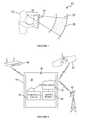
- FIG. 1is a schematic diagram of a system and/or device according to a preferred embodiment of the present invention.
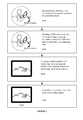
- FIG. 2is a schematic diagram of a system, device, and/or operating environment according to a preferred embodiment of the present invention.
- FIG. 3is a flowchart depicting a method for embedding a media file in a VAR scene according to a preferred embodiment of the present invention.
- FIG. 4is a schematic diagram of the method for embedding a media file in a VAR scene according to a variation of the preferred embodiment of the present invention.
- FIG. 5is a flowchart depicting a method for viewing a media file in a VAR scene according to a preferred embodiment of the present invention.
- FIG. 6is a schematic diagram of the method for viewing a media file in a VAR scene according to a variation of the preferred embodiment of the present invention.
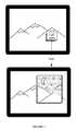
- FIG. 7is a schematic diagram of an example variation of the system and/or method of the preferred embodiment of the present invention.
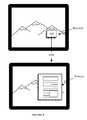
- FIG. 8is a schematic diagram of another example variation of the system and/or method of the preferred embodiment of the present invention.
- a system 10 of a preferred embodimentcan include a device 14 for embedding and/or viewing media files in virtual and augmented reality (VAR) scenes.
- VARvirtual and augmented reality
- the user device 14 and the viewer device 14are defined in terms of the function being performed by the respective user/viewer, and each type of device 14 is interchangeable with the other as described herein depending upon the use the device 14 is being put to by the user/viewer.
- the preferred user device 14can be used by a user to capture, process, create, and/or generate a viewable scene, such as for example a VAR scene, and to generate, place, position, embed and/or actuate one or more media files inside the VAR scene.
- the preferred viewer device 14can be used by a viewer to receive, process, orient, render, generate, and/or view a viewable scene, such as for example a VAR scene, and to render, view, activate, and/or interact with one or more media files inside the VAR scene.
- a viewable scenesuch as for example a VAR scene
- the user device 14 and the viewer device 14are substantially similar.
- One or both of the user device 14 and the viewer device 14can include one or more cameras (front/rear), an accelerometer, a gyroscope, a MEMS gyroscope, a magnetometer, a pedometer, a proximity sensor, an infrared sensor, an ultrasound sensor, a global position satellite transceiver, WiFi transceiver, mobile telephone components, and/or any suitable combination thereof for calculating a projection matrix and/or the associated Euler angles.
- orientation and/or position informationcan be gathered in any suitable fashion, including device Application Programming Interfaces (API) or through any suitable API exposing device information, e.g., using Flash or HTML5 to expose device information including orientation/location.
- APIApplication Programming Interfaces
- FlashHyperText Markup Language
- HTML5HyperText Markup Language
- the VAR scenecan include a spherical image 20 .
- the portion of the spherical imagei.e., the VAR scene 18
- the portion of the spherical imagethat is displayable by the device 14 corresponds to an overlap between a viewing frustum of the device (i.e., a viewing cone projected from the device) and the imaginary sphere that includes the spherical image 20 .
- the scene 18is preferably a portion of the spherical image 20 , which can include a substantially rectangular display of a concave, convex, or hyperbolic rectangular portion of the sphere of the spherical image 20 .
- the nodal pointis disposed at approximately the origin of the spherical image 20 , such that a viewer 12 has the illusion of being located at the center of a larger sphere or bubble having the VAR scene displayed on its interior.
- the nodal pointcan be disposed at any other suitable vantage point within the spherical image 20 displayable by the device 14 .
- the displayable scenecan include a substantially planar and/or ribbon-like geometry from which the nodal point is distanced in a constant or variable fashion.
- the display of the scene 18can be performed within a 3D or 2D graphics platform such as OpenGL, WebGL, or Direct 3D.
- the display of the scene 18can be performed within a browser environment using one or more of Flash, HTML5, CSS3, or any other suitable markup language.
- the geometry of the displayable scenecan be altered and/or varied in response to an automated input and/or in response to a user input.
- the (user and/or viewer mobile) device 14 of the preferred embodimentcan include a display 40 , an orientation module 50 including a real orientation module and a user orientation module, a location module 60 , a camera 90 oriented in substantially the same direction as the display 40 , and a processor 70 connected to each of the display, orientation module 50 , location module 60 , and camera 90 .
- the device 14 of the preferred embodimentpreferably functions to capture and/or present a VAR scene to a user from the point of view of a nodal point or center thereof, such that it appears to the user that he or she is viewing the world (represented by the VAR scene) through a frame of a window.
- the device 14 of the preferred embodimentcan include any suitable type of mobile computing apparatus such as a smart phone, a personal computer, a laptop computer, a tablet computer, a television/monitor paired with a separate handheld orientation/location apparatus, or any suitable combination thereof.
- the orientation module 50 of the device 14 of the preferred embodimentincludes at least a real orientation portion and a user orientation portion.
- the real orientation portion of the orientation module 50preferably functions to provide a frame of reference for the device 14 as it relates to a world around it, wherein the world around can include real three dimensional space, a virtual reality space, an augmented reality space, or any suitable combination thereof.
- the projection matrixcan preferably include a mathematical representation of an arbitrary orientation of a three-dimensional object (i.e., the device 14 ) having three degrees of freedom relative to a second frame of reference.
- the projection matrixcan include a mathematical representation of the device 14 orientations in terms of its Euler angles (pitch, roll, yaw) in any suitable coordinate system.
- the second frame of referencecan include a three-dimensional external frame of reference (i.e., real space) in which the gravitational force defines baseline directionality for the relevant coordinate system against which the absolute orientation of the device 14 can be measured.
- the device 14will have certain orientations corresponding to real world orientations, such as up and down, and further such that the device 14 can be rolled, pitched, and/or yawed within the external frame of reference.
- the orientation module 50can include a MEMS gyroscope configured to calculate and/or determine a projection matrix indicative of the orientation of the device 14 .
- the MEMS gyroscopecan be integral with the orientation module 50 .
- the MEMS gyroscopecan be integrated into any other suitable portion of the device 14 or maintained as a discrete module of its own.
- the user orientation portion of the orientation module 50preferably functions to provide a frame of reference for the device 14 relative to a point or object in space, including a point or object in real space.
- the user orientationcan include a measurement of a distance and/or rotational value/s of the device relative to a nodal point.
- the nodal pointcan include a user's head such that the user orientation includes a measurement of the relative distance and/or rotational value/s of the device 14 relative to a user's field of view.
- the nodal pointcan include a portion of the user's head, such as for example a point between the user's eyes.
- the nodal pointcan include any other suitable point in space, including for example any arbitrary point such as an inanimate object, a group of users, a landmark, a location, a waypoint, a predetermined coordinate, and the like.
- the user orientation portion of the orientation module 50can function to create a viewing relationship between a viewer 12 (optionally located at the nodal point) and the device 14 , such that a change in user orientation can cause a consummate change in viewable content consistent with the user's VAR interaction, i.e., such that the user's view through the frame will be adjusted consistent with the user's orientation relative to the frame.
- one variation of the device 14 of the preferred embodimentincludes a location module 60 connected to the processor 70 and the orientation module 50 .
- the location module 60 of the preferred embodimentfunctions to determine a location of the device 14 .
- locationcan refer to a geographic location, which can be indoors, outdoors, above ground, below ground, in the air or on board an aircraft or other vehicle.
- the device 14 of the preferred embodimentcan be connectable, either through wired or wireless means, to one or more of a satellite positioning system 82 , a local area network or wide area network such as a WiFi network 80 , and/or a cellular communication network 84 .
- a suitable satellite position system 82can include for example the Global Positioning System (GPS) constellation of satellites, Galileo, GLONASS, or any other suitable territorial or national satellite positioning system.
- GPSGlobal Positioning System
- the location module 60 of the preferred embodimentcan include a GPS transceiver, although any other type of transceiver for satellite-based location services can be employed in lieu of or in addition to a GPS transceiver.
- the processor 70 of the device 14 of the preferred embodimentfunctions to manage the presentation of the VAR scene to the viewer 12 .
- the processor 14preferably functions to display a scene to the viewer 12 on the display 40 in response to the real orientation and the user orientation.
- the processor 70 of the preferred embodimentcan be configured to process, compute, calculate, determine, and/or create a VAR scene that can be displayed on the device 14 to a viewer 12 , wherein the VAR scene is oriented to mimic the effect of the viewer 12 viewing the VAR scene as if through the frame of the device 12 .
- orienting the scenecan include preparing a VAR scene for display such that the viewable scene matches what the user would view in a real three-dimensional view, that is, such that the displayable scene provides a simulation of real viewable space to the viewer 12 as if the device 14 were a transparent frame.
- the sceneis preferably a VAR scene; therefore it can include one or more virtual and/or augmented reality elements composing, in addition to, and/or in lieu of one or more real elements (buildings, roads, landmarks, and the like, either real or fictitious).
- the scenecan include processed or unprocessed images/videos/multimedia files of one or more displayable scene aspects, including both actual and fictitious elements as noted above.
- the device 14can be configured in any suitable combination of hardware, firmware, and/or software for both embedding and activating media links within the displayable VAR scenes according to any of the preferred methods and variations thereof.
- a methodcan include: at a user device, defining a real orientation of the user device relative to a projection matrix in block S 100 ; orienting a VAR scene on the user device in response to the real orientation in block S 102 .
- the VAR sceneincludes at least visual data and orientation data.
- the first preferred methodcan further include selecting a media location in the VAR scene in the VAR scene in block S 104 ; and embedding a media file in the VAR scene at the media location in block S 106 .
- the media locationin correlated at least to the real orientation of the user device.
- the first preferred methodfunctions to allow a user to embed, tag, link, and/or associate a secondary media file with a VAR scene with which the user is interacting.
- the first preferred methodcan be performed on a user device of the type described above with reference to FIGS. 1 and 2 .
- the first preferred methodcan include block S 100 , which recites defining a real orientation of the user device relative to a projection matrix.
- Block S 100preferably functions to determine a physical orientation of the user device relative to an external frame of reference with which a secondary or additional media element is to be associated.
- the physical orientation of the user devicecan include the real orientation of the user device as calibrated relative to an external three-dimensional frame of reference.
- a suitable external frame of referencecan include a natural frame of reference in which a vertical axis is defined substantially collinearly with a gravitational pull on the user device.
- the user devicecan be configured to set and/or establish any suitable frame of reference and/or rotation or permutation thereof in determining the real orientation of the user device.
- block S 100can further include determining a location of the user device, wherein the location can include a geographic location, which can be indoors, outdoors, above ground, below ground, in the air or on board an aircraft or other vehicle.
- the real orientation and/or the locationcan include a fictional frame of reference and/or location, such as within a VAR scene related to a film or novel.
- One variation of the first preferred methodcan further include defining a user orientation of the user device relative to a nodal point.
- the user orientationcan include a measurement of a distance and/or rotational value/s of the device relative to a nodal point.
- the nodal pointcan include a user's head such that the user orientation includes a measurement of the relative distance and/or rotational value/s of the device relative to a user's field of view.
- the nodal pointcan include a portion of the user's head, such as for example a point between the user's eyes.
- the nodal pointcan include any other suitable point in space, including for example any arbitrary point such as an inanimate object, a group of users, a landmark, a location, a waypoint, a predetermined coordinate, and the like.
- determining the user orientationfunctions to create a viewing relationship between a user and/or viewer (optionally located at the nodal point) and the device, such that a change in user orientation can cause a consummate change in viewable content consistent with the user's VAR interaction, i.e., such that the user's view through the frame will be adjusted consistent with the user's orientation relative to the frame.
- the first preferred methodcan further include block S 102 , which recites orienting a VAR scene on the user device in response to the real orientation.
- Block S 102preferably functions to render, configure, calculate, compute, and/or display the VAR scene to the user in response to at least the real orientation of the user device.
- the VAR sceneincludes both visual data and orientation data, such that the portion of the scene that is displayable to the user is a function of the real orientation of the user device.
- the portion of the VAR scene that is displayable by the user devicecorresponds to an overlap between a viewing frustum of the device (i.e., a viewing cone projected from the device) and the imaginary sphere that includes the spherical image as shown in FIG. 1 .
- the VAR sceneis preferably a portion of the spherical image, which can include a substantially rectangular display of a concave, convex, or hyperbolic rectangular portion of the sphere of the spherical image.
- the nodal pointcan be disposed at approximately the origin of the spherical image, such that a user/viewer has the illusion of being located at the center of a larger sphere or bubble having the VAR scene displayed on its interior.
- the nodal pointcan be disposed at any other suitable vantage point within the spherical image displayable by the device.
- the displayable scenecan include a substantially planar and/or ribbon-like geometry from which the nodal point is distanced in a constant or variable fashion.
- block S 102can be performed within a 3D or 2D graphics platform such as OpenGL, WebGL, or Direct 3D.
- the orientation and/or display of the VAR scenecan be performed within a browser environment using one or more of Flash, HTML5, CSS3, or any other suitable markup language.
- the geometry of the displayable scenecan be altered and/or varied in response to an automated input and/or in response to a user input.
- the preferred methodcan further include block S 104 , which recites selecting a media location in the VAR scene and wherein the media location is correlated at least to the real orientation of the user device.
- Block S 104preferably functions to establish in the VAR scene a particular location, correlated to a particular orientation of the user/viewer device, at which the media file can be disposed for embedding and subsequent viewing and/or interaction by a viewer.
- block S 104can be performed at the user device in conjunction with a user manipulating the user device to change the portion of the VAR scene that is displayed on the user device as described above.
- the user devicecan respond to one or more user inputs to locate and/or register the media location as correlated to any combination of the real orientation, the user orientation, and/or the user device location.
- Suitable user inputscan include for example a touch, keystroke input, gesture, voice command, and/or any suitable combination thereof.
- the media locationcan include a range in display space correlated to a pixel area of the display which in turn correlates to a real orientation range of the projection matrix of the user device, which can be matrix analogs to ranges of associated pitch, roll, and yaw values for the user device.
- the media locationcan be further correlated to a depth value within the VAR scene.
- depthis communicated through either varying scale of the link data or by varying the Z depth of the link (e.g., when rendered on top of and after the rest of the VAR scene).
- An alternative approach, enabling out of order drawingincludes rendering the VAR scene close (i.e., inside a photosphere) and scaling according to the perspective transform along the plane formed by the X axis and Y axis.
- Any suitable technique for generating a depth valuecan be used, including a user input such as a touch, keystroke input, gesture, voice command, or other manipulation of the user device.
- the depth valuecan be determined solely in response to one or more of the user device real orientation, user orientation, and/or the location of the VAR scene.
- block S 104can further include assigning a location to the VAR scene, which can include for example receiving an input from an authoring tool in assigning a location of the VAR scene.
- Authoringcan include indicating location during authoring the VAR scene or while viewing a previously created VAR scene. For example, while creating a VAR scene on a mobile device, the user can initiate the assignment of a location by orientating the device in the desired location and then recording an audio clip. The audio clip will now be assigned that location within the VAR scene.
- links, text, multimedia, and other forms of mediacan be authored in any suitable manner.
- a location module of the type described abovecan automatically generate the location.
- image processingcan be employed to align the image with a corresponding view from the VAR scene.
- mediahas location information enabling relative positioning of the VAR scene and the media, then the location can be determined through the relative positioning. For example, if a second VAR scene is directly north of a first VAR scene, then the second VAR scene can be assigned a location in the northern portion of the first VAR scene.
- selecting the media location of the second VAR scenecan further include determining a location of the second VAR scene and locating the second VAR scene at its location within the VAR scene.
- the media location of the second VAR scenecan be automatically or manually located at the North tower in the VAR scene. Accordingly, viewer selection of the North tower can link the viewer directly to the second VAR scene.
- the preferred methodcan further include block S 106 , which recites embedding a media file in the VAR scene at the media location.
- the media filecan include any one of an image file, a video file, an audio file, a second VAR scene, a second rendering of the VAR scene, a hyperlink, or any other suitable type of ancillary media the content of which was not originally captured in the VAR scene.
- a hyperlinkcan be configured to direct the viewer device to the media file.
- the media filecan include an embedded media fragment that optionally can include a fully qualified file format.
- a viewercan click on or otherwise select the hyperlink which directs the viewer device to the media file, which can include any one of an image file, a video file, an audio file, a second VAR scene, a second rendering of the VAR scene, and/or a second hyperlink to still more media file/s.
- the media filecan be embedded into the VAR scene using any suitable process, algorithm, software suite, programming language, or application programming interface (API) including for example any suitable combination of OpenGL, WebGL, Direct 3D, Flash, HTML5, and/or CSS3.
- APIapplication programming interface
- block S 106can include embedding the media file in the VAR scene in more than one type of format, such that the media file can be accessed when the viewer device is operating in different locations or under different conditions (e.g., with or without access to WiFi or high-speed cellular network communications).
- the mediacan be rendered directly into the VAR scene such as an image positioned in a VAR scene.
- Flash or HTML5can be used to render the media links.
- uniform resource identifier (URI) linkscan be represented in a VAR scene with Flash, HTML or any other markup language, and Flash or HTML5 transforms or other suitable methods can be used to render the media links.
- URIuniform resource identifier
- the preferred methodcan further include block S 108 , which recites associating a media activation parameter with the media file.
- Block S 108preferably functions to correlate, generate, calculate, monitor, maintain, and/or associate a media activation parameter with the media file and/or the associated media location.
- the media activation parametercan include any suitable user interface through which the user/viewer can activate the media file.
- the media activation parametercan include a receivable user input, such as a touch, keystroke input, gesture, voice command, or other manipulation of the user device.
- the media activation parametercan include an activation area, the location of which defined by the orientation of the device relative to the VAR scene.
- the activation areais displayable within the VAR scene such that through manipulation of the orientation of the VAR scene, the activation area can be substantially overlapping with the media file and thus activate the media file.
- the activation areacan be substantially overlapping with the media file and thus activate the media file.
- reorientation of the devicesuch that activation area surrounds or otherwise at least partially overlaps the media file can result in activation of the media file, in this case an audio file that recites, “Here are the Rocky Mountains.”
- the activation areais disposed substantially in and around the center of the display, i.e., the activation area is a fixed range of pixels displayable in or around the center of the display.
- the size of the activation areacan be related to the size of the display of the device on which the VAR scene is being rendered, whether a user device or a viewer device.
- the size of the activation areacan be related to the number of and/or spatial density of media files. For example, if a VAR scene has a large number of selectable media files that are densely located, then the activation area can be relatively small to permit precise selection of the desired media file.
- the activation areacan be relatively large thus permitting a viewer greater latitude in selecting the desired media file. Accordingly, as the VAR scene is traversed by the user/viewer, the portions of the VAR scene disposed within the activation area will change accordingly. As the media file, which is embedded at the media location selected in block S 104 , is displayed within the activation area the media file will be activated. Activation of the media file can include any suitable action depending upon the type of media file that is being activated, such as playing the media file if it is an audio or video file, rendering an image file, following a hyperlink, and/or rendering and displaying a second VAR scene.
- the activation areacan be used alone or in combination with other means or mechanisms for activating the media file, including at least touch, keypad, and voice enabled interaction with the VAR scene.
- a second preferred methodcan include at a viewer device, defining a real orientation of the viewer device relative to a projection matrix in block 200 ; and orienting a VAR scene on the viewer device in response to the real orientation in block S 202 .
- the VAR sceneincludes one or both of visual data and orientation data.
- the second preferred methodcan further include selecting a media file in the VAR scene, wherein the media file is selected at a media location correlated at least to the real orientation of the viewer device in block S 204 ; and activating the media file in the VAR scene at the media location in block S 206 .
- the second preferred methodfunctions to allow a viewer to interact with media that is embedded, tagged, linked, and/or associated with a VAR scene viewable on the viewer device.
- the second preferred methodcan be performed on a viewer device of the type described above with reference to FIGS. 1 and 2 .
- the second preferred methodcan include block S 200 , which recites defining a real orientation of the viewer device relative to a projection matrix.
- Block S 200preferably functions to determine a physical orientation of the viewer device relative to an external frame of reference with which a secondary or additional media element is to be associated.
- the physical orientation of the viewer devicecan include the real orientation of the viewer device as calibrated relative to an external three-dimensional frame of reference.
- a suitable external frame of referencecan include a natural frame of reference in which a vertical axis is defined substantially collinearly with a gravitational pull on the viewer device.
- the viewer devicecan be configured to set and/or establish any suitable frame of reference and/or rotation or permutation thereof in determining the real orientation of the viewer device.
- block S 200can further include determining a location of the viewer device, wherein the location can include a geographic location, which can be indoors, outdoors, above ground, below ground, in the air or on board an aircraft or other vehicle.
- the real orientation and/or the locationcan include a fictional frame of reference and/or location, such as within a VAR scene related to a film or novel.
- One variation of the second preferred methodcan further include defining a user orientation of the viewer device relative to a nodal point.
- the user orientationcan include a measurement of a distance and/or rotational value/s of the device relative to a nodal point.
- the nodal pointcan include a viewer's head such that the user orientation includes a measurement of the relative distance and/or rotational value/s of the device relative to a viewer's field of view.
- the nodal pointcan include a portion of the viewer's head, such as for example a point between the viewer's eyes.
- the nodal pointcan include any other suitable point in space, including for example any arbitrary point such as an inanimate object, a group of users, a landmark, a location, a waypoint, a predetermined coordinate, and the like.
- determining the user orientationfunctions to create a viewing relationship between a viewer (optionally located at the nodal point) and the device, such that a change in user orientation can cause a consummate change in viewable content consistent with the user's VAR interaction, i.e., such that the viewer's view through the frame will be adjusted consistent with the viewer's orientation relative to the frame.
- the second preferred methodcan further include block S 202 , which recites orienting a VAR scene on the viewer device in response to the real orientation.
- Block S 202preferably functions to render, configure, calculate, compute, and/or display the VAR scene to the viewer in response to at least the real orientation of the viewer device.
- the VAR scenepreferably includes both visual data and orientation data, such that the portion of the scene that is displayable to the viewer is a function of the real orientation of the viewer device.
- the portion of the VAR scene that is displayable by the viewer devicecorresponds to an overlap between a viewing frustum of the device (i.e., a viewing cone projected from the device) and the imaginary sphere that includes the spherical image as shown in FIG. 1 .
- the VAR sceneis preferably a portion of the spherical image, which can include a substantially rectangular display of a concave, convex, or hyperbolic rectangular portion of the sphere of the spherical image.
- the nodal pointcan be disposed at approximately the origin of the spherical image, such that a user/viewer has the illusion of being located at the center of a larger sphere or bubble having the VAR scene displayed on its interior.
- the nodal pointcan be disposed at any other suitable vantage point within the spherical image displayable by the device.
- the displayable scenecan include a substantially planar and/or ribbon-like geometry from which the nodal point is distanced in a constant or variable fashion.
- block S 202can be performed within a 3D or 2D graphics platform such as OpenGL, WebGL, or Direct 3D.
- the orientation and/or display of the VAR scenecan be performed within a browser environment using one or more of Flash, HTML5, CSS3, or any other suitable markup language.
- the geometry of the displayable scenecan be altered and/or varied in response to an automated input and/or in response to a viewer input.
- the second preferred methodcan further include block S 204 , which recites selecting a media file in the VAR scene, wherein the media file is selected at a media location correlated at least to the real orientation of the user device.
- Block S 204preferably functions to allow a viewer to interact with, choose, and/or select a media file in the VAR scene at particular location correlated to a particular orientation of the viewer device.
- block S 204can be performed at the viewer device in conjunction with a viewer manipulating the viewer device to change the portion of the VAR scene that is displayed on the viewer device as described above.
- the viewer devicecan respond to one or more viewer inputs to choose and/or select the media location as correlated to any combination of the real orientation, the user orientation, and/or the viewer device location.
- Suitable viewer inputscan include for example a touch, keystroke input, gesture, voice command, and/or any suitable combination thereof.
- the media locationcan include a range in display space correlated to a pixel area of the display which in turn correlates to a real orientation range of the projection matrix of the viewer device, which can be matrix analogs to ranges of associated pitch, roll, and yaw values for the viewer device. Accordingly, in response to the viewer orienting the viewer device in a particular orientation, the appropriate media file can be selected.
- the media locationcan be further correlated to a depth value within the VAR scene.
- depthis communicated through either varying scale of the link data or by varying the Z depth of the link (e.g., when rendered on top of and after the rest of the VAR scene).
- a previously noted alternative approach, enabling out of order drawingincludes rendering the VAR scene close (i.e., inside a photosphere) and scaling according to the perspective transform along the plane formed by the X axis and Y axis.
- Any suitable technique for selecting a depth valuecan be used, including a user input such as a touch, keystroke input, gesture, voice command, or other manipulation of the viewer device.
- the depth valuecan be determined solely in response to one or more of the viewer device real orientation, user orientation, and/or the location of the VAR scene.
- the second preferred methodcan further include block S 206 , which recites activating the media file in the VAR scene at the media location.
- the media filecan include any one of an image file, a video file, an audio file, a second VAR scene, a second rendering of the VAR scene, a hyperlink, or any other suitable type of ancillary media the content of which was not originally captured in the VAR scene.
- a hyperlinkcan be configured to direct the viewer device to the media file.
- a hyperlinkcan be configured to direct the viewer device to the media file.
- the media filecan include an embedded media fragment that optionally can include a fully qualified file format.
- a viewercan click on or otherwise select the hyperlink which directs the viewer device to the media file, which can include any one of an image file, a video file, an audio file, a second VAR scene, a second rendering of the VAR scene, and/or a second hyperlink to still more media file/s.
- the media filecan be embedded into the VAR scene using any suitable process, algorithm, software suite, programming language, or application programming interface (API) including for example any suitable combination of OpenGL, WebGL, Direct 3D, Flash, HTML5, and/or CSS3.
- APIapplication programming interface
- activating the media filecan include at least causing the media file to transmit/communicate its desired content, such as for example playing an audio or video file, displaying an image, retrieving a webpage, rendering and displaying a second VAR scene, and/or following a hyperlink.
- block S 206can include activating the media file in the VAR scene in more than one type of format, such that the media file can be accessed when the viewer device is operating in different locations or under different conditions (e.g., with or without access to WiFi or high-speed cellular network communications).
- the media location of the second VAR scenecan include a representation of the second VAR scene at its real location within the VAR scene. As noted above, if a second VAR scene is directly north of a first VAR scene, then the second VAR scene can be assigned a location in the northern portion of the first VAR scene. In another example implementation described above, selecting the media location of the second VAR scene can further include determining a location of the second VAR scene and locating the second VAR scene at its location within the VAR scene.
- the media location of the second VAR scenecan be automatically or manually located at the North tower in the VAR scene. Accordingly, viewer selection of the North tower can link the viewer directly to the second VAR scene.
- activation of example types of media filescan result in the display and/or transmission of different types of media within the displayed VAR scene.
- FIG. 6for example illustrates another variation of the second preferred method in which activation of the media file can include activating the media file in response to an orientation of the viewer device such that an activation area in the VAR scene overlaps the media file.
- suitable media activation parameterscan include any suitable user interface through which the user/viewer can activate the media file.
- the media activation parametercan include a receivable user input, such as a touch, keystroke input, gesture, voice command, or other manipulation of the user device.
- the media activation parametercan include an activation area displayable within the VAR scene such that through manipulation of the orientation of the VAR scene, the activation area can be substantially overlapping with the media file and thus activate the media file.
- activation areacan result in activation of the media file, in this case an audio file that recites, “Here are the Rocky Mountains.”
- activation of the example media file shown in FIG. 7can result in the display of a nighttime image of the portion of the Rocky Mountains with which the media file is associated by location and/or user orientation.
- FIG. 8by contrast illustrates an example webpage media file in which activation of the hyperlink causes retrieval and display of a webpage relating to the portion of the Rocky Mountains with which the media file (hyperlink) is associated by location and/or user orientation.
- binaural audiocan be incorporated into the playback to simulate the audio originating from the location within the VAR scene.
- the audiocan continue but will use internal time and level differences or other binaural techniques to create the perception of the sound originating from a stationary point. For example, when looking north an audio file can be played sounding as if it is originating from a northerly source. When the viewer turns south to view other portions of the VAR scene, the sound can be transmitted as if it is still coming from a northerly direction behind the viewer.
- the volume of playbackcan change based on orientation such that the volume is greater when the audio link is in the center of the display and quieter when not viewed.
- the audiocan alternatively be prepared such that a surround sound experience is created; in which case, the mixing of the audio alters depending on the orientation of the user/viewer.
- image processingcan be used to align the image with the VAR scene imagery as described above.
- the media fileis preferably graphically represented via either text or graphics.
- a sound media filecan have a sound graphic positioned at the location of the sound file in the VAR scene.
- the media filecan alternatively be generally hidden and selectively viewable in the VAR scene in response to the real orientation of the viewer device.
- the visibility of the media filecan additionally be toggled in response to a real orientation or viewing mode of the viewer device.
- a predetermined real orientation, user orientation, and/or location of the devicecan activate interactive controls or a “hover” state of the media file. For example, when a second VAR scene link is substantially in the center of the display a text description, image preview, or other information relating to the second VAR scene can be displayed. Additionally or alternatively, activation or selection of the media file can cause the display of one or more media controls such as play or volume to permit further interaction with the media file.
- activating a second VAR scenecauses the display of transition between the two VAR scenes.
- the transitionis a video of images showing the transition between the locations associated with the two VAR scenes.
- the displayed image of the current VAR scenecan transition to an image of the second VAR scene in the same orientation.
- a graphical animation of moving between the location of the first VAR scene and the second VAR scenecan be displayed on a map.
- the second VAR scenepreferably has a reciprocating VAR scene link to allow a transition back to the original VAR scene.
- a network of links between VAR scenescan be provided allowing exploration of spatial scenes while the user/viewer device remains in a single location.
- the links for the respective VAR scenescan be user generated or automatically created based on which VAR scenes are popular, close by, or interrelated in any other suitable way.
- Additional variations of the preferred methodscan additionally include automatically embedding a VAR scene, which functions to automatically populate a VAR scene with suitable links.
- a database or map of VAR scenesis preferably used to identify nearby, associated, and/or popular VAR scenes to which to link.
- the link to an identified VAR sceneis preferably added and the location is preferably based on the relative geographic location of the two VAR scenes as described above.
- This automatic embedding of linkspreferably creates a navigable space from and between discrete VAR scenes. Additionally other content can be automatically included. For example, based on the location of the VAR scene links to other media files can be embedded.
- a link to a media file containing a review of that restaurantcan be embedded and preferably positioned in the direction of the restaurant.
- Links from other nearby VAR scenes that were manually addedcan additionally be automatically embedded into a VAR scene.
- a nearby VAR scenehas a link to media file containing an informative webpage
- a VAR scenecan embed that same informative webpage as its own media file.
- Outside content from other sourcessuch as a social network with geo-tagged content can additionally be used to auto-populate a VAR scene with links to one or more media files.
- the user and viewer devices 14 and methods of the preferred embodimentcan be embodied and/or implemented at least in part as a machine configured to receive a computer-readable medium storing computer-readable instructions.
- the instructionsare preferably executed by computer-executable components preferably integrated with the user/viewer device 14 and one or more portions of the processor 70 , orientation module 50 and/or location module 60 .
- Other systems and methods of the preferred embodimentcan be embodied and/or implemented at least in part as a machine configured to receive a computer-readable medium storing computer-readable instructions.
- the instructionsare preferably executed by computer-executable components preferably integrated by computer-executable components preferably integrated with a user/viewer device 14 of the type described above.
- the computer-readable mediumcan be stored on any suitable computer readable media such as RAMs, ROMs, flash memory, EEPROMs, optical devices (CD or DVD), hard drives, floppy drives, or any suitable device.
- the computer-executable componentis preferably a processor but any suitable dedicated hardware device can (alternatively or additionally) execute the instructions.
Landscapes
- Engineering & Computer Science (AREA)
- Signal Processing (AREA)
- Multimedia (AREA)
- Business, Economics & Management (AREA)
- Databases & Information Systems (AREA)
- Human Computer Interaction (AREA)
- General Engineering & Computer Science (AREA)
- Life Sciences & Earth Sciences (AREA)
- Biodiversity & Conservation Biology (AREA)
- Ecology (AREA)
- Emergency Management (AREA)
- Environmental & Geological Engineering (AREA)
- Environmental Sciences (AREA)
- Remote Sensing (AREA)
- User Interface Of Digital Computer (AREA)
Abstract
Description
Claims (15)
Priority Applications (1)
| Application Number | Priority Date | Filing Date | Title |
|---|---|---|---|
| US13/411,347US9118970B2 (en) | 2011-03-02 | 2012-03-02 | System and method for embedding and viewing media files within a virtual and augmented reality scene |
Applications Claiming Priority (3)
| Application Number | Priority Date | Filing Date | Title |
|---|---|---|---|
| US201161448327P | 2011-03-02 | 2011-03-02 | |
| US201161451071P | 2011-03-09 | 2011-03-09 | |
| US13/411,347US9118970B2 (en) | 2011-03-02 | 2012-03-02 | System and method for embedding and viewing media files within a virtual and augmented reality scene |
Publications (2)
| Publication Number | Publication Date |
|---|---|
| US20120236029A1 US20120236029A1 (en) | 2012-09-20 |
| US9118970B2true US9118970B2 (en) | 2015-08-25 |
Family
ID=46828090
Family Applications (1)
| Application Number | Title | Priority Date | Filing Date |
|---|---|---|---|
| US13/411,347Active2032-06-26US9118970B2 (en) | 2011-03-02 | 2012-03-02 | System and method for embedding and viewing media files within a virtual and augmented reality scene |
Country Status (1)
| Country | Link |
|---|---|
| US (1) | US9118970B2 (en) |
Cited By (4)
| Publication number | Priority date | Publication date | Assignee | Title |
|---|---|---|---|---|
| US9723226B2 (en) | 2010-11-24 | 2017-08-01 | Aria Glassworks, Inc. | System and method for acquiring virtual and augmented reality scenes by a user |
| US10068383B2 (en) | 2012-10-02 | 2018-09-04 | Dropbox, Inc. | Dynamically displaying multiple virtual and augmented reality views on a single display |
| US11367259B2 (en) | 2013-03-14 | 2022-06-21 | Dropbox, Inc. | Method for simulating natural perception in virtual and augmented reality scenes |
| US11854149B2 (en) | 2014-02-21 | 2023-12-26 | Dropbox, Inc. | Techniques for capturing and displaying partial motion in virtual or augmented reality scenes |
Families Citing this family (18)
| Publication number | Priority date | Publication date | Assignee | Title |
|---|---|---|---|---|
| US8907983B2 (en) | 2010-10-07 | 2014-12-09 | Aria Glassworks, Inc. | System and method for transitioning between interface modes in virtual and augmented reality applications |
| US9070219B2 (en) | 2010-11-24 | 2015-06-30 | Aria Glassworks, Inc. | System and method for presenting virtual and augmented reality scenes to a user |
| US9041743B2 (en) | 2010-11-24 | 2015-05-26 | Aria Glassworks, Inc. | System and method for presenting virtual and augmented reality scenes to a user |
| US8953022B2 (en) | 2011-01-10 | 2015-02-10 | Aria Glassworks, Inc. | System and method for sharing virtual and augmented reality scenes between users and viewers |
| EP2754131B1 (en) | 2011-09-08 | 2022-10-26 | Nautilus, Inc. | System and method for visualizing synthetic objects withinreal-world video clip |
| KR101407670B1 (en)* | 2011-09-15 | 2014-06-16 | 주식회사 팬택 | Mobile terminal, server and method for forming communication channel using augmented reality |
| US20130282715A1 (en)* | 2012-04-20 | 2013-10-24 | Samsung Electronics Co., Ltd. | Method and apparatus of providing media file for augmented reality service |
| US9153073B2 (en) | 2012-05-23 | 2015-10-06 | Qualcomm Incorporated | Spatially registered augmented video |
| US8989444B2 (en)* | 2012-06-15 | 2015-03-24 | Bae Systems Information And Electronic Systems Integration Inc. | Scene correlation |
| GB201303707D0 (en)* | 2013-03-01 | 2013-04-17 | Tosas Bautista Martin | System and method of interaction for mobile devices |
| US9762848B2 (en) | 2013-03-15 | 2017-09-12 | Google Inc. | Automatic adjustment of video orientation |
| KR20170012312A (en)* | 2014-06-02 | 2017-02-02 | 에이펠랩 에스에이알엘 | A method and system for providing interactivity within a virtual environment |
| EP3023863A1 (en)* | 2014-11-20 | 2016-05-25 | Thomson Licensing | Device and method for processing visual data, and related computer program product |
| US9704298B2 (en) | 2015-06-23 | 2017-07-11 | Paofit Holdings Pte Ltd. | Systems and methods for generating 360 degree mixed reality environments |
| AU2017280088A1 (en)* | 2016-06-22 | 2019-05-02 | Southern Star Corporation Pty Ltd | System and methods for delivery of audio and video content |
| WO2018027067A1 (en)* | 2016-08-05 | 2018-02-08 | Pcms Holdings, Inc. | Methods and systems for panoramic video with collaborative live streaming |
| US10217000B2 (en)* | 2017-01-17 | 2019-02-26 | International Business Machines Corporation | Context-based extraction and information overlay for photographic images |
| US12333065B1 (en) | 2018-10-08 | 2025-06-17 | Floreo, Inc. | Customizing virtual and augmented reality experiences for neurodevelopmental therapies and education |
Citations (72)
| Publication number | Priority date | Publication date | Assignee | Title |
|---|---|---|---|---|
| US5287437A (en) | 1992-06-02 | 1994-02-15 | Sun Microsystems, Inc. | Method and apparatus for head tracked display of precomputed stereo images |
| US5841439A (en) | 1994-07-22 | 1998-11-24 | Monash University | Updating graphical objects based on object validity periods |
| US5990941A (en) | 1991-05-13 | 1999-11-23 | Interactive Pictures Corporation | Method and apparatus for the interactive display of any portion of a spherical image |
| US6226669B1 (en) | 1997-12-19 | 2001-05-01 | Jiung-Yao Huang | Mutli-user 3D virtual reality interaction system utilizing protocol data units for data communication among WWW server and clients |
| US20010030693A1 (en) | 2000-03-06 | 2001-10-18 | Fisher Clay H. | System and method for creating still images by utilizing a video camera device |
| US6389179B1 (en)* | 1996-05-28 | 2002-05-14 | Canon Kabushiki Kaisha | Image combining apparatus using a combining algorithm selected based on an image sensing condition corresponding to each stored image |
| US20020140666A1 (en) | 2001-03-29 | 2002-10-03 | Bradski Gary R. | Intuitive mobile device interface to virtual spaces |
| US20020158873A1 (en) | 2001-01-26 | 2002-10-31 | Todd Williamson | Real-time virtual viewpoint in simulated reality environment |
| US6760026B2 (en) | 2001-01-02 | 2004-07-06 | Microsoft Corporation | Image-based virtual reality player with integrated 3D graphics objects |
| US20050219239A1 (en) | 2004-03-31 | 2005-10-06 | Sanyo Electric Co., Ltd. | Method and apparatus for processing three-dimensional images |
| US20050286125A1 (en) | 2004-06-24 | 2005-12-29 | Henrik Sundstrom | Proximity assisted 3D rendering |
| US20060050140A1 (en) | 2004-09-08 | 2006-03-09 | Jae-Gyoung Shin | Wireless communication terminal and its method for generating moving picture using still image |
| US20060082692A1 (en) | 2004-10-15 | 2006-04-20 | Seiko Epson Corporation | Image display device and projector |
| US20070025723A1 (en)* | 2005-07-28 | 2007-02-01 | Microsoft Corporation | Real-time preview for panoramic images |
| US20070035562A1 (en)* | 2002-09-25 | 2007-02-15 | Azuma Ronald T | Method and apparatus for image enhancement |
| US20070076016A1 (en) | 2005-10-04 | 2007-04-05 | Microsoft Corporation | Photographing big things |
| US20070103543A1 (en)* | 2005-08-08 | 2007-05-10 | Polar Industries, Inc. | Network panoramic camera system |
| US7224326B2 (en)* | 2004-03-03 | 2007-05-29 | Volo, Llc | Virtual reality system |
| US20070168418A1 (en) | 2005-12-23 | 2007-07-19 | Nitesh Ratnakar | Web Page to Cellular Phone - Contact Information Messaging System |
| US20070236493A1 (en) | 2003-05-27 | 2007-10-11 | Keiji Horiuchi | Image Display Apparatus and Program |
| US20080042973A1 (en) | 2006-07-10 | 2008-02-21 | Memsic, Inc. | System for sensing yaw rate using a magnetic field sensor and portable electronic devices using the same |
| US20080071559A1 (en) | 2006-09-19 | 2008-03-20 | Juha Arrasvuori | Augmented reality assisted shopping |
| US20080082692A1 (en) | 2006-09-29 | 2008-04-03 | Takehide Yano | Dialog apparatus, dialog method, and computer program |
| US20080094417A1 (en) | 2005-08-29 | 2008-04-24 | Evryx Technologies, Inc. | Interactivity with a Mixed Reality |
| US7389591B2 (en) | 2005-05-17 | 2008-06-24 | Gesturetek, Inc. | Orientation-sensitive signal output |
| US20080194323A1 (en) | 2005-04-06 | 2008-08-14 | Eidgenoessische Technische Hochschule Zuerich | Method Of Executing An Application In A Mobile Device |
| WO2008107553A2 (en) | 2007-01-22 | 2008-09-12 | Total Immersion | Augmented reality method and devices using a real time automatic tracking of marker-free textured planar geometrical objects in a video stream |
| US20080266326A1 (en) | 2007-04-25 | 2008-10-30 | Ati Technologies Ulc | Automatic image reorientation |
| US20080280676A1 (en) | 2007-05-07 | 2008-11-13 | Samsung Electronics Co. Ltd. | Wireless gaming method and wireless gaming-enabled mobile terminal |
| US20080292131A1 (en) | 2006-08-10 | 2008-11-27 | Canon Kabushiki Kaisha | Image capture environment calibration method and information processing apparatus |
| US20080309508A1 (en) | 2006-11-25 | 2008-12-18 | John Paul Harmon | Accelerometer based extended display |
| US20080320422A1 (en) | 2004-08-31 | 2008-12-25 | Freescale Semiconductor, Inc. | Design Rule Checking System |
| US20090140887A1 (en) | 2007-11-29 | 2009-06-04 | Breed David S | Mapping Techniques Using Probe Vehicles |
| US20090240431A1 (en)* | 2008-03-24 | 2009-09-24 | Google Inc. | Panoramic Images Within Driving Directions |
| US20090237564A1 (en) | 2008-03-18 | 2009-09-24 | Invism, Inc. | Interactive immersive virtual reality and simulation |
| US20090244097A1 (en)* | 2008-03-25 | 2009-10-01 | Leonardo William Estevez | System and Method for Providing Augmented Reality |
| US20090292774A1 (en)* | 2005-08-16 | 2009-11-26 | Thomson Licensing | Method and Apparatus for Electronic Message Delivery |
| US20100002122A1 (en) | 2008-07-03 | 2010-01-07 | Erik Larson | Camera system and method for picture sharing using geotagged pictures |
| US20100001980A1 (en) | 2008-07-07 | 2010-01-07 | Lg Electronics Inc. | Mobile terminal and method of controlling operation of the mobile terminal |
| US20100007657A1 (en) | 2005-09-15 | 2010-01-14 | Rurin Oleg Stanislavovich | Method and system for visualization of virtual three-dimensional objects |
| US20100066763A1 (en) | 2008-09-12 | 2010-03-18 | Gesturetek, Inc. | Orienting displayed elements relative to a user |
| US20100092079A1 (en)* | 2008-10-14 | 2010-04-15 | Joshua Victor Aller | Target and method of detecting, identifying, and determining 3-d pose of the target |
| US20100125816A1 (en)* | 2008-11-20 | 2010-05-20 | Bezos Jeffrey P | Movement recognition as input mechanism |
| US20100161658A1 (en) | 2004-12-31 | 2010-06-24 | Kimmo Hamynen | Displaying Network Objects in Mobile Devices Based on Geolocation |
| US20100169837A1 (en) | 2008-12-29 | 2010-07-01 | Nortel Networks Limited | Providing Web Content in the Context of a Virtual Environment |
| US20100171758A1 (en) | 2006-12-18 | 2010-07-08 | Reallaer LLC | Method and system for generating augmented reality signals |
| US20100188397A1 (en)* | 2009-01-28 | 2010-07-29 | Apple Inc. | Three dimensional navigation using deterministic movement of an electronic device |
| US20100214111A1 (en)* | 2007-12-21 | 2010-08-26 | Motorola, Inc. | Mobile virtual and augmented reality system |
| US20100228633A1 (en) | 2009-03-09 | 2010-09-09 | Guimaraes Stella Villares | Method and system for hosting a metaverse environment within a webpage |
| US20100287485A1 (en)* | 2009-05-06 | 2010-11-11 | Joseph Bertolami | Systems and Methods for Unifying Coordinate Systems in Augmented Reality Applications |
| US20110041060A1 (en)* | 2009-08-12 | 2011-02-17 | Apple Inc. | Video/Music User Interface |
| US20110090252A1 (en) | 2009-10-20 | 2011-04-21 | Samsung Electronics Co., Ltd. | Markerless augmented reality system and method using projective invariant |
| US20110164116A1 (en) | 2010-01-04 | 2011-07-07 | Disney Enterprises, Inc. | Video capture system control using virtual cameras for augmented reality |
| US20110201362A1 (en)* | 2010-02-12 | 2011-08-18 | Samsung Electronics Co., Ltd. | Augmented Media Message |
| US20110213861A1 (en) | 2006-10-12 | 2011-09-01 | Bobby Fanelli | Next Generation Social Networking And Content Rating System And Method |
| US20110242134A1 (en) | 2010-03-30 | 2011-10-06 | Sony Computer Entertainment Inc. | Method for an augmented reality character to maintain and exhibit awareness of an observer |
| US20110248987A1 (en)* | 2010-04-08 | 2011-10-13 | Disney Enterprises, Inc. | Interactive three dimensional displays on handheld devices |
| US20110273451A1 (en) | 2010-05-10 | 2011-11-10 | Salemann Leo J | Computer simulation of visual images using 2d spherical images extracted from 3d data |
| US20120086728A1 (en)* | 2010-10-07 | 2012-04-12 | Terrence Edward Mcardle | System and method for transitioning between interface modes in virtual and augmented reality applications |
| US20120105440A1 (en) | 2010-06-25 | 2012-05-03 | Lieberman Stevan H | Augmented Reality System |
| US20120113264A1 (en) | 2010-11-10 | 2012-05-10 | Verizon Patent And Licensing Inc. | Multi-feed event viewing |
| US20120214590A1 (en) | 2010-11-24 | 2012-08-23 | Benjamin Zeis Newhouse | System and method for acquiring virtual and augmented reality scenes by a user |
| US20120212405A1 (en) | 2010-10-07 | 2012-08-23 | Benjamin Zeis Newhouse | System and method for presenting virtual and augmented reality scenes to a user |
| US20120218306A1 (en) | 2010-11-24 | 2012-08-30 | Terrence Edward Mcardle | System and method for presenting virtual and augmented reality scenes to a user |
| US20120242656A1 (en) | 2010-11-24 | 2012-09-27 | Aria Glassworks, Inc. | System and method for presenting virtual and augmented reality scenes to a user |
| US20120246223A1 (en) | 2011-03-02 | 2012-09-27 | Benjamin Zeis Newhouse | System and method for distributing virtual and augmented reality scenes through a social network |
| US20120242798A1 (en) | 2011-01-10 | 2012-09-27 | Terrence Edward Mcardle | System and method for sharing virtual and augmented reality scenes between users and viewers |
| US8373573B2 (en) | 2010-06-15 | 2013-02-12 | Transcend Information, Inc. | Display system adapting to 3D tilting adjustment |
| US8384718B2 (en) | 2008-01-10 | 2013-02-26 | Sony Corporation | System and method for navigating a 3D graphical user interface |
| US20140092135A1 (en) | 2012-10-02 | 2014-04-03 | Aria Glassworks, Inc. | System and method for dynamically displaying multiple virtual and augmented reality scenes on a single display |
| US8730156B2 (en) | 2010-03-05 | 2014-05-20 | Sony Computer Entertainment America Llc | Maintaining multiple views on a shared stable virtual space |
| US20140267418A1 (en) | 2013-03-14 | 2014-09-18 | Aria Glassworks, Inc. | Method for simulating natural perception in virtual and augmented reality scenes |
- 2012
- 2012-03-02USUS13/411,347patent/US9118970B2/enactiveActive
Patent Citations (80)
| Publication number | Priority date | Publication date | Assignee | Title |
|---|---|---|---|---|
| US5990941A (en) | 1991-05-13 | 1999-11-23 | Interactive Pictures Corporation | Method and apparatus for the interactive display of any portion of a spherical image |
| US5287437A (en) | 1992-06-02 | 1994-02-15 | Sun Microsystems, Inc. | Method and apparatus for head tracked display of precomputed stereo images |
| US5841439A (en) | 1994-07-22 | 1998-11-24 | Monash University | Updating graphical objects based on object validity periods |
| US6389179B1 (en)* | 1996-05-28 | 2002-05-14 | Canon Kabushiki Kaisha | Image combining apparatus using a combining algorithm selected based on an image sensing condition corresponding to each stored image |
| US6226669B1 (en) | 1997-12-19 | 2001-05-01 | Jiung-Yao Huang | Mutli-user 3D virtual reality interaction system utilizing protocol data units for data communication among WWW server and clients |
| US7133068B2 (en) | 2000-03-06 | 2006-11-07 | Sony Corporation | System and method for creating still images by utilizing a video camera device |
| US20010030693A1 (en) | 2000-03-06 | 2001-10-18 | Fisher Clay H. | System and method for creating still images by utilizing a video camera device |
| US6760026B2 (en) | 2001-01-02 | 2004-07-06 | Microsoft Corporation | Image-based virtual reality player with integrated 3D graphics objects |
| US20020158873A1 (en) | 2001-01-26 | 2002-10-31 | Todd Williamson | Real-time virtual viewpoint in simulated reality environment |
| US20020140666A1 (en) | 2001-03-29 | 2002-10-03 | Bradski Gary R. | Intuitive mobile device interface to virtual spaces |
| US20040027330A1 (en)* | 2001-03-29 | 2004-02-12 | Bradski Gary R. | Intuitive mobile device interface to virtual spaces |
| US20070035562A1 (en)* | 2002-09-25 | 2007-02-15 | Azuma Ronald T | Method and apparatus for image enhancement |
| US20070236493A1 (en) | 2003-05-27 | 2007-10-11 | Keiji Horiuchi | Image Display Apparatus and Program |
| US7224326B2 (en)* | 2004-03-03 | 2007-05-29 | Volo, Llc | Virtual reality system |
| US20050219239A1 (en) | 2004-03-31 | 2005-10-06 | Sanyo Electric Co., Ltd. | Method and apparatus for processing three-dimensional images |
| US20050286125A1 (en) | 2004-06-24 | 2005-12-29 | Henrik Sundstrom | Proximity assisted 3D rendering |
| US20080320422A1 (en) | 2004-08-31 | 2008-12-25 | Freescale Semiconductor, Inc. | Design Rule Checking System |
| US20060050140A1 (en) | 2004-09-08 | 2006-03-09 | Jae-Gyoung Shin | Wireless communication terminal and its method for generating moving picture using still image |
| US20060082692A1 (en) | 2004-10-15 | 2006-04-20 | Seiko Epson Corporation | Image display device and projector |
| US8301159B2 (en) | 2004-12-31 | 2012-10-30 | Nokia Corporation | Displaying network objects in mobile devices based on geolocation |
| US20100161658A1 (en) | 2004-12-31 | 2010-06-24 | Kimmo Hamynen | Displaying Network Objects in Mobile Devices Based on Geolocation |
| US20080194323A1 (en) | 2005-04-06 | 2008-08-14 | Eidgenoessische Technische Hochschule Zuerich | Method Of Executing An Application In A Mobile Device |
| US7389591B2 (en) | 2005-05-17 | 2008-06-24 | Gesturetek, Inc. | Orientation-sensitive signal output |
| US7424218B2 (en) | 2005-07-28 | 2008-09-09 | Microsoft Corporation | Real-time preview for panoramic images |
| US20070025723A1 (en)* | 2005-07-28 | 2007-02-01 | Microsoft Corporation | Real-time preview for panoramic images |
| US20070103543A1 (en)* | 2005-08-08 | 2007-05-10 | Polar Industries, Inc. | Network panoramic camera system |
| US20090292774A1 (en)* | 2005-08-16 | 2009-11-26 | Thomson Licensing | Method and Apparatus for Electronic Message Delivery |
| US20080094417A1 (en) | 2005-08-29 | 2008-04-24 | Evryx Technologies, Inc. | Interactivity with a Mixed Reality |
| US7564469B2 (en) | 2005-08-29 | 2009-07-21 | Evryx Technologies, Inc. | Interactivity with a mixed reality |
| US20100007657A1 (en) | 2005-09-15 | 2010-01-14 | Rurin Oleg Stanislavovich | Method and system for visualization of virtual three-dimensional objects |
| US20070076016A1 (en) | 2005-10-04 | 2007-04-05 | Microsoft Corporation | Photographing big things |
| US7499586B2 (en) | 2005-10-04 | 2009-03-03 | Microsoft Corporation | Photographing big things |
| US20070168418A1 (en) | 2005-12-23 | 2007-07-19 | Nitesh Ratnakar | Web Page to Cellular Phone - Contact Information Messaging System |
| US20080042973A1 (en) | 2006-07-10 | 2008-02-21 | Memsic, Inc. | System for sensing yaw rate using a magnetic field sensor and portable electronic devices using the same |
| US20080292131A1 (en) | 2006-08-10 | 2008-11-27 | Canon Kabushiki Kaisha | Image capture environment calibration method and information processing apparatus |
| US20080071559A1 (en) | 2006-09-19 | 2008-03-20 | Juha Arrasvuori | Augmented reality assisted shopping |
| US20080082692A1 (en) | 2006-09-29 | 2008-04-03 | Takehide Yano | Dialog apparatus, dialog method, and computer program |
| US8041574B2 (en) | 2006-09-29 | 2011-10-18 | Kabushiki Kaisha Toshiba | Dialog apparatus, dialog method, and computer program |
| US20110213861A1 (en) | 2006-10-12 | 2011-09-01 | Bobby Fanelli | Next Generation Social Networking And Content Rating System And Method |
| US20080309508A1 (en) | 2006-11-25 | 2008-12-18 | John Paul Harmon | Accelerometer based extended display |
| US20100171758A1 (en) | 2006-12-18 | 2010-07-08 | Reallaer LLC | Method and system for generating augmented reality signals |
| WO2008107553A2 (en) | 2007-01-22 | 2008-09-12 | Total Immersion | Augmented reality method and devices using a real time automatic tracking of marker-free textured planar geometrical objects in a video stream |
| US20080266326A1 (en) | 2007-04-25 | 2008-10-30 | Ati Technologies Ulc | Automatic image reorientation |
| US20080280676A1 (en) | 2007-05-07 | 2008-11-13 | Samsung Electronics Co. Ltd. | Wireless gaming method and wireless gaming-enabled mobile terminal |
| US20090140887A1 (en) | 2007-11-29 | 2009-06-04 | Breed David S | Mapping Techniques Using Probe Vehicles |
| US20100214111A1 (en)* | 2007-12-21 | 2010-08-26 | Motorola, Inc. | Mobile virtual and augmented reality system |
| US8384718B2 (en) | 2008-01-10 | 2013-02-26 | Sony Corporation | System and method for navigating a 3D graphical user interface |
| US20090237564A1 (en) | 2008-03-18 | 2009-09-24 | Invism, Inc. | Interactive immersive virtual reality and simulation |
| US20090240431A1 (en)* | 2008-03-24 | 2009-09-24 | Google Inc. | Panoramic Images Within Driving Directions |
| US20090244097A1 (en)* | 2008-03-25 | 2009-10-01 | Leonardo William Estevez | System and Method for Providing Augmented Reality |
| US20100002122A1 (en) | 2008-07-03 | 2010-01-07 | Erik Larson | Camera system and method for picture sharing using geotagged pictures |
| US8144232B2 (en)* | 2008-07-03 | 2012-03-27 | Sony Ericsson Mobile Communications Ab | Camera system and method for picture sharing using geotagged pictures |
| US20100001980A1 (en) | 2008-07-07 | 2010-01-07 | Lg Electronics Inc. | Mobile terminal and method of controlling operation of the mobile terminal |
| US20100066763A1 (en) | 2008-09-12 | 2010-03-18 | Gesturetek, Inc. | Orienting displayed elements relative to a user |
| US20100092079A1 (en)* | 2008-10-14 | 2010-04-15 | Joshua Victor Aller | Target and method of detecting, identifying, and determining 3-d pose of the target |
| US20100125816A1 (en)* | 2008-11-20 | 2010-05-20 | Bezos Jeffrey P | Movement recognition as input mechanism |
| US20100169837A1 (en) | 2008-12-29 | 2010-07-01 | Nortel Networks Limited | Providing Web Content in the Context of a Virtual Environment |
| US20100188397A1 (en)* | 2009-01-28 | 2010-07-29 | Apple Inc. | Three dimensional navigation using deterministic movement of an electronic device |
| US20100228633A1 (en) | 2009-03-09 | 2010-09-09 | Guimaraes Stella Villares | Method and system for hosting a metaverse environment within a webpage |
| US20100287485A1 (en)* | 2009-05-06 | 2010-11-11 | Joseph Bertolami | Systems and Methods for Unifying Coordinate Systems in Augmented Reality Applications |
| US20110041060A1 (en)* | 2009-08-12 | 2011-02-17 | Apple Inc. | Video/Music User Interface |
| US20110090252A1 (en) | 2009-10-20 | 2011-04-21 | Samsung Electronics Co., Ltd. | Markerless augmented reality system and method using projective invariant |
| US20110164116A1 (en) | 2010-01-04 | 2011-07-07 | Disney Enterprises, Inc. | Video capture system control using virtual cameras for augmented reality |
| US20110201362A1 (en)* | 2010-02-12 | 2011-08-18 | Samsung Electronics Co., Ltd. | Augmented Media Message |
| US8730156B2 (en) | 2010-03-05 | 2014-05-20 | Sony Computer Entertainment America Llc | Maintaining multiple views on a shared stable virtual space |
| US20110242134A1 (en) | 2010-03-30 | 2011-10-06 | Sony Computer Entertainment Inc. | Method for an augmented reality character to maintain and exhibit awareness of an observer |
| US20110248987A1 (en)* | 2010-04-08 | 2011-10-13 | Disney Enterprises, Inc. | Interactive three dimensional displays on handheld devices |
| US20110273451A1 (en) | 2010-05-10 | 2011-11-10 | Salemann Leo J | Computer simulation of visual images using 2d spherical images extracted from 3d data |
| US8373573B2 (en) | 2010-06-15 | 2013-02-12 | Transcend Information, Inc. | Display system adapting to 3D tilting adjustment |
| US20120105440A1 (en) | 2010-06-25 | 2012-05-03 | Lieberman Stevan H | Augmented Reality System |
| US20120212405A1 (en) | 2010-10-07 | 2012-08-23 | Benjamin Zeis Newhouse | System and method for presenting virtual and augmented reality scenes to a user |
| US20120086728A1 (en)* | 2010-10-07 | 2012-04-12 | Terrence Edward Mcardle | System and method for transitioning between interface modes in virtual and augmented reality applications |
| US20120113264A1 (en) | 2010-11-10 | 2012-05-10 | Verizon Patent And Licensing Inc. | Multi-feed event viewing |
| US20120218306A1 (en) | 2010-11-24 | 2012-08-30 | Terrence Edward Mcardle | System and method for presenting virtual and augmented reality scenes to a user |
| US20120242656A1 (en) | 2010-11-24 | 2012-09-27 | Aria Glassworks, Inc. | System and method for presenting virtual and augmented reality scenes to a user |
| US20120214590A1 (en) | 2010-11-24 | 2012-08-23 | Benjamin Zeis Newhouse | System and method for acquiring virtual and augmented reality scenes by a user |
| US20120242798A1 (en) | 2011-01-10 | 2012-09-27 | Terrence Edward Mcardle | System and method for sharing virtual and augmented reality scenes between users and viewers |
| US20120246223A1 (en) | 2011-03-02 | 2012-09-27 | Benjamin Zeis Newhouse | System and method for distributing virtual and augmented reality scenes through a social network |
| US20140092135A1 (en) | 2012-10-02 | 2014-04-03 | Aria Glassworks, Inc. | System and method for dynamically displaying multiple virtual and augmented reality scenes on a single display |
| US20140267418A1 (en) | 2013-03-14 | 2014-09-18 | Aria Glassworks, Inc. | Method for simulating natural perception in virtual and augmented reality scenes |
Non-Patent Citations (12)
| Title |
|---|
| "Motion Control Simulation Applet" http://ir.exp.sis.pitt.edu/res2/data/is/group5/. Archived on Sep. 1, 2006. Retrieved onNov. 5, 2013 from . |
| "Motion Control Simulation Applet" http://ir.exp.sis.pitt.edu/res2/data/is/group5/. Archived on Sep. 1, 2006. Retrieved onNov. 5, 2013 from <https://web.archive.org/web/20060901110520/http://ir.exp.sis.pitt.edu/res2/data/is/group5/>. |
| "Rotations and Euler angles" http://www.easyspin.org/documentation/eulerangles.html. Archived on Apr. 6, 2008. Retrieved on Nov. 5, 2013 from . |
| "Rotations and Euler angles" http://www.easyspin.org/documentation/eulerangles.html. Archived on Apr. 6, 2008. Retrieved on Nov. 5, 2013 from <https://web.archive.org/web/20080406234538/http://www.easyspin.org/documentation/eulerangles.html>. |
| Ducket, Jon, "Beginning HTML, XHTML, CSS, and JavaScript (R)," Dec. 30, 2009, Wrox, p. 234. |
| Easypano Holdings Inc, "Panoweaver 6.00 User Manual", Copyright Easypano Holdings Inc., date unknown, downloaded from http://web.archive.org/web/20090711113513/http://www.easypano.com/download/doc/pw600-manual.pdf with an archive.orgverified date of Jul. 11, 2009, pp. 24-74. |
| Fauster, Loris, and T. U. Wien. "Stereoscopic techniques in computer graphics." Tu Wien (2007), 10 pages. |
| Hewlett Packard, "HP Photosmart R717 Digital Camera with HP Instant Share User's Manual", Copyright 2005 Hewlett-Packard Development Company, L.P., downloaded from http://h1 0032.www1.hp.com/ctg/Manual/c00298985.pdf on May 3, 2013, pp. 50-54. |
| Hildenbrand, Jerry; "Yelp 2.0 brings monocle and checkins to its Android Client,"; located at http:/www.androidcentral.com/yelp-20-brings-monocle-andcheckins-its-android-client; Jul. 5, 2010; 10 pages. |
| Hwang et al. "Hand-held virtual reality: a feasibility study." Proceedings of the ACM symposium on Virtual reality software and technology. ACM, 2006. |
| Kanbara, Masayuki, et al. "A stereoscopic video see-through augmented reality system based on real-time vision-based registration." Virtual Reality, 2000. Proceedings. IEEE. IEEE, 2000, 8 pages. |
| Parr62, Ben; "EASTER EGG: Yelp Is the iPhone's First Augmented Reality App,"; located at https://web.archive.org/web/20090829094113/http://mashable.com/2009/08/2007/yelp-aug . . . ; Aug. 27, 2009; 10 pages. |
Cited By (9)
| Publication number | Priority date | Publication date | Assignee | Title |
|---|---|---|---|---|
| US9723226B2 (en) | 2010-11-24 | 2017-08-01 | Aria Glassworks, Inc. | System and method for acquiring virtual and augmented reality scenes by a user |
| US10462383B2 (en) | 2010-11-24 | 2019-10-29 | Dropbox, Inc. | System and method for acquiring virtual and augmented reality scenes by a user |
| US10893219B2 (en) | 2010-11-24 | 2021-01-12 | Dropbox, Inc. | System and method for acquiring virtual and augmented reality scenes by a user |
| US11381758B2 (en) | 2010-11-24 | 2022-07-05 | Dropbox, Inc. | System and method for acquiring virtual and augmented reality scenes by a user |
| US10068383B2 (en) | 2012-10-02 | 2018-09-04 | Dropbox, Inc. | Dynamically displaying multiple virtual and augmented reality views on a single display |
| US11367259B2 (en) | 2013-03-14 | 2022-06-21 | Dropbox, Inc. | Method for simulating natural perception in virtual and augmented reality scenes |
| US11893701B2 (en) | 2013-03-14 | 2024-02-06 | Dropbox, Inc. | Method for simulating natural perception in virtual and augmented reality scenes |
| US11854149B2 (en) | 2014-02-21 | 2023-12-26 | Dropbox, Inc. | Techniques for capturing and displaying partial motion in virtual or augmented reality scenes |
| US12211160B2 (en) | 2014-02-21 | 2025-01-28 | Dropbox, Inc. | Techniques for capturing and displaying partial motion in virtual or augmented reality scenes |
Also Published As
| Publication number | Publication date |
|---|---|
| US20120236029A1 (en) | 2012-09-20 |
Similar Documents
| Publication | Publication Date | Title |
|---|---|---|
| US9118970B2 (en) | System and method for embedding and viewing media files within a virtual and augmented reality scene | |
| US12211160B2 (en) | Techniques for capturing and displaying partial motion in virtual or augmented reality scenes | |
| US11967029B2 (en) | Media tags—location-anchored digital media for augmented reality and virtual reality environments | |
| US9041743B2 (en) | System and method for presenting virtual and augmented reality scenes to a user | |
| US9223408B2 (en) | System and method for transitioning between interface modes in virtual and augmented reality applications | |
| US20120212405A1 (en) | System and method for presenting virtual and augmented reality scenes to a user | |
| CN102598064B (en) | Method for rendering virtual information in view of real environment | |
| CN102473324B (en) | Method for representing virtual information in a real environment | |
| Simon et al. | A mobile application framework for the geospatial web | |
| US9361283B2 (en) | Method and system for projecting text onto surfaces in geographic imagery | |
| AU2011211601B2 (en) | Method for providing information on object within view of terminal device, terminal device for same and computer-readable recording medium | |
| EP2806400B1 (en) | Image enhancement using a multi-dimensional model | |
| US20120218306A1 (en) | System and method for presenting virtual and augmented reality scenes to a user | |
| US20110310227A1 (en) | Mobile device based content mapping for augmented reality environment | |
| CN105302860A (en) | Techniques for manipulating panoramas | |
| WO2014033354A1 (en) | A method and apparatus for updating a field of view in a user interface | |
| JP5363971B2 (en) | Landscape reproduction system | |
| Liarokapis et al. | Mobile augmented reality techniques for geovisualisation | |
| US20230333809A1 (en) | Immersive Audio Tours | |
| CN114511687B (en) | A method, system, electronic device and readable storage medium for integrating virtual space and real space | |
| US20140316905A1 (en) | System and method for three-dimensional advertising | |
| CA2943247A1 (en) | Method and system for dynamically positioning, viewing and sharing location based mixed reality content | |
| Tahir | Global Positioning System (GPS) Based Location Finder on Android | |
| Holweg et al. | Augmented reality visualization of geospatial data |
Legal Events
| Date | Code | Title | Description |
|---|---|---|---|
| AS | Assignment | Owner name:ARIA GLASSWORKS, INC., CALIFORNIA Free format text:ASSIGNMENT OF ASSIGNORS INTEREST;ASSIGNORS:NEWHOUSE, BENJAMIN ZEIS;MCARDLE, TERRENCE EDWARD;REEL/FRAME:028355/0384 Effective date:20120608 | |
| STCF | Information on status: patent grant | Free format text:PATENTED CASE | |
| AS | Assignment | Owner name:JPMORGAN CHASE BANK, N.A., AS COLLATERAL AGENT, NE Free format text:SECURITY INTEREST;ASSIGNOR:DROPBOX, INC.;REEL/FRAME:042254/0001 Effective date:20170403 Owner name:JPMORGAN CHASE BANK, N.A., AS COLLATERAL AGENT, NEW YORK Free format text:SECURITY INTEREST;ASSIGNOR:DROPBOX, INC.;REEL/FRAME:042254/0001 Effective date:20170403 | |
| MAFP | Maintenance fee payment | Free format text:PAYMENT OF MAINTENANCE FEE, 4TH YEAR, LARGE ENTITY (ORIGINAL EVENT CODE: M1551); ENTITY STATUS OF PATENT OWNER: LARGE ENTITY Year of fee payment:4 | |
| AS | Assignment | Owner name:JPMORGAN CHASE BANK, N.A., AS COLLATERAL AGENT, NEW YORK Free format text:PATENT SECURITY AGREEMENT;ASSIGNOR:DROPBOX, INC.;REEL/FRAME:055670/0219 Effective date:20210305 | |
| MAFP | Maintenance fee payment | Free format text:PAYMENT OF MAINTENANCE FEE, 8TH YEAR, LARGE ENTITY (ORIGINAL EVENT CODE: M1552); ENTITY STATUS OF PATENT OWNER: LARGE ENTITY Year of fee payment:8 | |
| AS | Assignment | Owner name:WILMINGTON TRUST, NATIONAL ASSOCIATION, AS COLLATERAL AGENT, DELAWARE Free format text:SECURITY INTEREST;ASSIGNOR:DROPBOX, INC.;REEL/FRAME:069604/0611 Effective date:20241211 Owner name:DROPBOX, INC., CALIFORNIA Free format text:RELEASE BY SECURED PARTY;ASSIGNOR:JPMORGAN CHASE BANK, N.A., AS COLLATERAL AGENT;REEL/FRAME:069613/0744 Effective date:20241211 | |
| AS | Assignment | Owner name:DROPBOX, INC., CALIFORNIA Free format text:RELEASE BY SECURED PARTY;ASSIGNOR:JPMORGAN CHASE BANK, N.A., AS COLLATERAL AGENT;REEL/FRAME:069635/0332 Effective date:20241211 |