US9118717B2 - Delayed network protocol proxy for packet inspection in a network - Google Patents
Delayed network protocol proxy for packet inspection in a networkDownload PDFInfo
- Publication number
- US9118717B2 US9118717B2US11/061,248US6124805AUS9118717B2US 9118717 B2US9118717 B2US 9118717B2US 6124805 AUS6124805 AUS 6124805AUS 9118717 B2US9118717 B2US 9118717B2
- Authority
- US
- United States
- Prior art keywords
- tcp
- entity
- connection
- packet
- data packet
- Prior art date
- Legal status (The legal status is an assumption and is not a legal conclusion. Google has not performed a legal analysis and makes no representation as to the accuracy of the status listed.)
- Expired - Fee Related, expires
Links
- 230000003111delayed effectEffects0.000titledescription8
- 238000007689inspectionMethods0.000titledescription2
- 238000000034methodMethods0.000claimsabstractdescription41
- 230000004044responseEffects0.000claimsdescription18
- 230000005540biological transmissionEffects0.000claimsdescription7
- 238000004891communicationMethods0.000description28
- 238000010586diagramMethods0.000description13
- 230000008520organizationEffects0.000description7
- 230000009471actionEffects0.000description5
- 230000003287optical effectEffects0.000description5
- 230000008569processEffects0.000description5
- 238000012545processingMethods0.000description4
- 238000013459approachMethods0.000description3
- 238000010276constructionMethods0.000description3
- 230000003993interactionEffects0.000description2
- 230000004048modificationEffects0.000description2
- 238000012986modificationMethods0.000description2
- 230000003068static effectEffects0.000description2
- RYGMFSIKBFXOCR-UHFFFAOYSA-NCopperChemical compound[Cu]RYGMFSIKBFXOCR-UHFFFAOYSA-N0.000description1
- 241000700605VirusesSpecies0.000description1
- 238000009825accumulationMethods0.000description1
- 230000004075alterationEffects0.000description1
- 238000004590computer programMethods0.000description1
- 230000008878couplingEffects0.000description1
- 238000010168coupling processMethods0.000description1
- 238000005859coupling reactionMethods0.000description1
- 230000001934delayEffects0.000description1
- 238000001514detection methodMethods0.000description1
- 230000001627detrimental effectEffects0.000description1
- 239000000835fiberSubstances0.000description1
- 230000006870functionEffects0.000description1
- 230000000977initiatory effectEffects0.000description1
- 230000007246mechanismEffects0.000description1
- 230000006855networkingEffects0.000description1
- 238000012546transferMethods0.000description1
Images


Classifications
- H—ELECTRICITY
- H04—ELECTRIC COMMUNICATION TECHNIQUE
- H04L—TRANSMISSION OF DIGITAL INFORMATION, e.g. TELEGRAPHIC COMMUNICATION
- H04L69/00—Network arrangements, protocols or services independent of the application payload and not provided for in the other groups of this subclass
- H04L69/16—Implementation or adaptation of Internet protocol [IP], of transmission control protocol [TCP] or of user datagram protocol [UDP]
- H04L69/163—In-band adaptation of TCP data exchange; In-band control procedures
- H—ELECTRICITY
- H04—ELECTRIC COMMUNICATION TECHNIQUE
- H04L—TRANSMISSION OF DIGITAL INFORMATION, e.g. TELEGRAPHIC COMMUNICATION
- H04L69/00—Network arrangements, protocols or services independent of the application payload and not provided for in the other groups of this subclass
- H04L69/24—Negotiation of communication capabilities
- H04L67/2819—
- H—ELECTRICITY
- H04—ELECTRIC COMMUNICATION TECHNIQUE
- H04L—TRANSMISSION OF DIGITAL INFORMATION, e.g. TELEGRAPHIC COMMUNICATION
- H04L67/00—Network arrangements or protocols for supporting network services or applications
- H04L67/50—Network services
- H04L67/56—Provisioning of proxy services
- H04L67/564—Enhancement of application control based on intercepted application data
Definitions
- the present inventiongenerally relates to proxy devices in computer networks.
- the inventionrelates more specifically to a method and apparatus for enabling an intermediary device to start behaving as a proxy device relative to two communicating entities after a connection already has been established between the two communicating entities.
- the entitiesmay communicate by sending data packets towards each other through one or more intervening networks. Routers, which are positioned between the entities, may intercept the data packets and forward the data packets towards the data packets' destinations. The entities typically remain unaware of the path taken by data packets through intervening networks and intermediary devices.
- IPInternet Protocol
- TCPTransport Control Protocol
- HTTPHypertext Transfer Protocol
- Some of these protocolsare connection-oriented. Connection-oriented protocols typically require connection-related parameters to be negotiated between entities to the connection before the connection is “opened.” Data can be sent through the connection only after these parameters have been negotiated and the connection has been opened.
- a handshake phaseusually requires a significant amount of communication between the entities.
- a handshake phasealso may require a significant amount of processing by the entities. Due to this communication and processing overhead, the transmission of substantive content between the entities may be delayed significantly.
- Intermediary devicessometimes include devices that take a relatively active role in the communications between two entities. For example, instead of merely forwarding intercepted data packets toward the data packets' destination, an intermediary device such as a firewall device might perform operations that require the accumulation of multiple data packets at the intermediary device prior to the sending of any of those data packets toward the destination. Due to some TCP characteristics, which are provided to enable TCP packet senders to verify that their TCP packets reach intended destinations, accumulating TCP packets at an intermediary device is more complicated than it might initially seem.
- TCPTCP
- the receiving entityis supposed to respond to the sending entity, from which the TCP packet originated, with an acknowledgement that identifies the TCP packet. If the sending entity receives the acknowledgement, then the sending entity can rest assured that the receiving entity actually received the corresponding TCP packet. Alternatively, if the sending entity does not receive the acknowledgement within a reasonable period of time, then the sending entity may assume that the receiving entity did not receive the corresponding TCP packet, and the sending entity may re-send the corresponding TCP packet.
- the sending entitywill not send additional TCP packets until the sending entity has received acknowledgements for TCP packets that the sending entity has already sent. If a firewall device has been intercepting and accumulating TCP packets instead of forwarding the TCP packets to the intended receiving entity, then the intended receiving entity will not have been returning any acknowledgements to the sending entity. Due to the missing acknowledgments, the sending entity may re-send TCP packets that the firewall device has already accumulated instead of sending additional TCP packets that the firewall device needs to accumulate in order to determine whether to forward any of the accumulated TCP packets toward the intended receiving entity. The sending entity and the firewall device each end up waiting for the other to perform an action that the other will never perform.
- the firewall devicewould send acknowledgements to the sending entity for each TCP packet that the firewall device received.
- the sending entitywould receive the acknowledgements and continue to send TCP packets toward the firewall device.
- thiswould also necessitate the shifting, from the sending entity to the firewall device, of the burden of ensuring that the TCP packets reached the intended receiving entity; having received an acknowledgement for a particular TCP packet, the sending device will not re-send the particular TCP packet thereafter, even if the particular TCP packet never actually reaches the intended receiving entity.
- the firewall devicewould need to receive acknowledgements from the receiving entity, and re-send any TCP packet for which no acknowledgement was received within a reasonable period of time.
- TCP connectionsneed to be established: one between the sending entity and the proxy device, and another between the proxy device and the receiving entity.
- establishing a TCP connection between two entitiesinvolves a time-consuming handshake phase.
- the sending entityengages in a first handshake phase with the firewall device, and then the firewall device engages in a second handshake phase with the receiving device. Because the negotiation of the second handshake phase depends on the negotiation of the first handshake phase, the two handshake phases cannot be performed concurrently. Until both handshake phases have been completed, TCP packets cannot flow between the sending entity and the receiving entity.
- the communication delay (latency) resulting from having to wait for two separate handshake phases to completeis both significant and undesirable.
- a TCP connection between a sending entity and a proxy devicemay be opened before the proxy device attempts to open a TCP connection with the intended receiving entity.
- the receiving entitymight not be available; the receiving entity might not respond to the proxy device's attempts to open a TCP connection with the receiving entity.
- the sending entitymay be left with the mistaken impression that a complete communication path to the receiving entity is available, when, in reality, the path ends at the proxy device. If the sending entity proceeds under this mistaken impression, the outcome may be unexpected and undesirable.
- a connection techniquethat allows an intermediary device to accumulate multiple separate TCP packets before sending the TCP packets toward a destination, and that additionally avoids the delays produced as a result of a series of handshake phases, is needed.
- FIG. 1is a block diagram that illustrates an overview of one embodiment of a system in which a proxy device forms two connections between entities based on connection parameters that the proxy device observes as the entities negotiate the connection parameters with each other;
- FIG. 3depicts a flow diagram that illustrates an overview of one embodiment of a method for “proxying” a client-to-server connection
- FIG. 5is a block diagram that illustrates a computer system upon which an embodiment may be implemented.
- a method and apparatus for enabling an intermediary device to start behaving as a proxy device relative to two communicating entities after a connection already has been established between the two communicating entitiesis described. Certain embodiments of the method allow an intermediary device to inspect a complete message, whose parts may be spread among the payload portions of multiple separate TCP packets, without engaging in time-consuming handshake phases with the message's origin and the message's destination.
- an intermediary devicestores the connection parameters as the parameters flow through the intermediary device.
- the intermediary deviceuses the intercepted parameters to form two separate connections in the place of the original connection: one connection between the intermediary device and the first entity, and another connection between the intermediary device and the second entity. All of this may be accomplished without the intermediary device separately negotiating connection parameters with either entity.
- the newly formed connectionsappear to be same as the original connection. Thus, the entities do not need to be aware of the actions performed by the intermediary device.
- the intermediary devicecan then behave as a proxy device relative to the entities.
- the devicemay send acknowledgements to a sending entity for each TCP packet that the device intercepts from the sending entity. Also, as a proxy device, the device may receive acknowledgements from a receiving entity, and re-send any TCP packet for which no acknowledgement was received within a reasonable period of time.
- the proxy devicemay take a relatively active role in the communications between two entities. For example, instead of merely forwarding intercepted data packets toward the data packets' destination, the proxy device might perform “deep” packet inspection by examining the contents of the payload portions of data packets. Based on the contents, the proxy device might perform one or more specified actions. For example, a firewall device that sits at the boundary of an organization's private network might examine the contents of all TCP packets that the firewall device intercepts. The firewall device may refuse to forward, into the organization's network, any TCP packet that belongs to a TCP packet sequence that contains content that matches a specified forbidden pattern.
- the firewall devicecan prevent viruses from infiltrating the organization's network. Additionally, by selectively refusing to forward such TCP packets, the firewall device can prevent the organization's network bandwidth from being used for unauthorized purposes. For example, if a organization doesn't want its employees to be able to use a particular peer-to-peer, networking application that would send messages to and receive messages from beyond the organization's network, the organization can configure the firewall device to detect a pattern that is known to occur only in messages that the application sends and receives, and to “drop” or modify all TCP packets that belong to any TCP packet sequence that contains the pattern.
- the inventionencompasses a computer apparatus and a computer-readable medium configured to carry out the foregoing steps.
- FIG. 1is a block diagram that illustrates an overview of one embodiment of a system 100 in which a proxy device 102 forms two connections between entities based on connection parameters that proxy device 102 observes as the entities negotiate the connection parameters with each other.
- Proxy device 102may be, for example, a firewall device or an intrusion detection system (IDS) device.
- IDSintrusion detection system
- proxy device 102may comprise a network node that does not perform proxy functions in other contexts.
- Proxy device 102is coupled communicatively with servers 104 A-N.
- servers 104 A-Nmay be a separate computer.
- each of servers 104 A-Nmay be a separate process executing on the same computer or on separate computers.
- each of servers 104 A-Nmay be a separate web server process.
- Proxy device 102also is coupled communicatively with a network 106 .
- Network 106is a computer network, such as, for example, a local area network (LAN), wide area network (WAN), or internetwork such as the Internet.
- Clients 108 A-Nalso are coupled communicatively with network 106 .
- Each of clients 108 A-Nmay be a separate computer.
- each of clients 108 A-Nmay be a separate process executing on the same computer or on separate computers.
- each of clients 108 A-Nmay be a separate web browser process.
- TCPis discussed below as a network protocol carrier of communications between clients 108 A-N and servers 104 A-N
- embodiments of the inventionalternatively may employ other network protocols that involve the negotiation or exchange of protocol-related parameters between entities that are initiating communications with each other.
- one of clients 108 A-Nopens a TCP connection with one of servers 104 A-N.
- client 108 Amay negotiate TCP connection parameters with server 104 A.
- the connection parameterspass through proxy device 102 as the parameters are communicated between client 108 A and server 104 A.
- Both client 108 A and server 104 Amay be unaware that the connection parameters are passing through proxy device 102 ; the network may be configured in such a manner that all communications between clients 108 A-N and servers 104 A-N pass through proxy device 102 .
- proxy device 102When proxy device 102 receives a parameter negotiation message from client 108 A or server 104 A, proxy device 102 forwards the message toward the message's indicated destination so that the handshake phase between client 108 A and server 104 A can be completed. However, before forwarding the message, proxy device 102 inspects the message to determine whether the message contains connection negotiation parameters. If proxy device 102 determines that the message contains connection negotiation parameters, then proxy device 102 locally stores one or more of the connection negotiation parameters. Proxy device 102 maps the stored parameters to the entities that are sending and receiving the parameters—in this example, client 108 A and server 104 A.
- client 108 A and server 104 Acan send TCP data packets to each other through the “original” TCP connection that they have opened based on the negotiated parameters.
- Such data packetsare carried in conformance with the negotiated parameters.
- the data packetsmay carry portions of request messages and response messages, such as HTTP requests and responses.
- proxy device 102may replace the original TCP connection with two separate TCP connections: one between client 108 A and proxy device 102 , and one between proxy device 102 and server 104 A. Proxy device 102 may accomplish this without the awareness of client 108 A and server 104 A. In one embodiment, proxy device 102 replaces the original connection with the separate connections as soon as proxy device 102 observes a data packet passing through the original connection.
- proxy device 102constructs two new TCP endpoints at proxy device 102 .
- Proxy device 102constructs the TCP endpoints using the connection parameters that are locally stored and mapped to the entities to the original connection—in this example, client 108 A and server 104 A.
- the proxy devicemay store the appropriate connection parameters in a separate TCP control block (TCB).
- TCP control blockTCP control block
- An existing endpoint at client 108 Aremains an endpoint in the new connection between client 108 A and proxy device 102 .
- an existing endpoint at server 104 Aremains an endpoint in the new connection between server 104 A and proxy device 102 .
- the combination of the client-to-proxy device connection and the corresponding proxy device-to-server connectionis called a “proxied” connection.
- Proxy device 102maps the new endpoints to each other, so that when proxy device 102 receives a data packet through one of the new endpoints, proxy device 102 may forward the data packet through the other, corresponding new endpoint. Before forwarding data packets, proxy device 102 may accumulate multiple data packets, reorder and assemble the contents of payload portions of those data packets to form a message, and inspect the message. Based on the contents of the message, proxy device 102 may perform one or more specified actions prior to, or instead of, forwarding the accumulated data packets. For example, proxy device may drop the data packets or modify the contents of the data packets.
- proxy device 102obtains some of the connection parameters from a data packet that proxy device 102 observes passing through the original connection. In such an embodiment, to create the new endpoints and connections, proxy device 102 uses the connection parameters obtained from the data packet in addition to the connection parameters that proxy device 102 observed and stored during the negotiations between the entities.
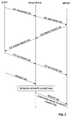
- FIG. 2is a diagram that illustrates a message communication sequence, according to one embodiment, by which an original client-to-server TCP connection is initially established.
- the message communication sequenceencompasses one performance of the “three-way handshake” protocol used in TCP—in this example, between a client and a server. All of the messages discussed below pass through a proxy device, where connection parameters contained within the messages are scrutinized and recorded.
- TCP SYN packet 202indicates TCP parameters that the client proposes for use in the forthcoming TCP connection.
- the TCP parameterstypically include, for example, a maximum segment size, a window scale factor, and flags that indicate whether time stamping and/or selective acknowledgment will be used.
- TCP SYN packet 202passes through an intermediate proxy device. By inspecting TCP SYN packet 202 prior to forwarding TCP SYN packet 202 on to the client, the proxy device determines the values of the TCP connection parameters that the client is proposing to the server.
- the proxy devicebefore forwarding TCP SYN packet 202 on toward the server, the proxy device modifies TCP SYN packet 202 ; for example, the proxy device may alter TCP SYN packet 202 , so that TCP SYN packet 202 does not propose any TCP connection parameters that the proxy device cannot support.
- the proxy devicemay modify acknowledgement and sequence numbers and other information contained in TCP SYN packet 202 as needed to compensate for the alteration.
- the serverreceives (potentially modified) TCP SYN packet 202 and responds with a TCP SYN/ACK packet 204 .
- TCP SYN/ACK packet 204indicates which of the client-proposed TCP parameters the server has accepted for use in the forthcoming TCP connection.
- TCP SYN/ACK packet 204passes through an intermediate proxy device. By inspecting TCP SYN/ACK packet 204 prior to forwarding TCP SYN/ACK packet 204 on to the client, the proxy device determines the values of the TCP connection parameters by which the server has agreed to abide.
- the clientreceives TCP SYN/ACK packet 204 and responds with a TCP ACK packet 206 .
- TCP SYN/ACK packet 204receives TCP SYN/ACK packet 204 and responds with a TCP ACK packet 206 .
- both the client and the servercreate TCP endpoints based on the TCP parameters negotiated during the handshake phase described above.
- TCP endpointsbased on the TCP parameters negotiated during the handshake phase described above.
- the clientsends a request 208 toward the server through the client's TCP endpoint.
- the proxy devicedetects request 208 as request 208 passes through the proxy device.
- the proxy devicemay replace the original TCP client-to-server TCP connection with the client-to-proxy device and proxy device-to-server TCP connections as described above.
- the proxy devicemay modify request 208 before sending request 208 to the server. Whether or not request 208 is modified, the proxy device sends request 208 to the server through the proxy device's TCP endpoint involved in the proxy device-to-server connection (i.e., not the proxy device's TCP endpoint involved in the client-to-proxy device connection). The server receives request 208 at the server's TCP endpoint.
- client-to-proxy device connection and the proxy device-to-server connectioncomprise a proxied connection.
- the proxy devicemay inspect TCP SYN/ACK packet 208 to obtain TCP connection parameters upon which the client and the server have agreed.
- the proxy devicestores the TCP connection parameters within separate connection block data structures as is described below.
- proxy device 102stores a tuple that indicates the client's IP address, the proxy device's IP address, a TCP protocol identifier, and an identifier of the client's TCP port used in the client-to-server connection, and an identifier of one of the proxy device's TCP ports.
- proxy device 102stores a tuple that indicates the proxy device's IP address, the server's IP address, a TCP protocol identifier, an identifier of one of the proxy device's TCP ports, and an identifier of the server's TCP port used in the client-to-server connection.
- proxy device 102stores a separate sequence delta that indicates to what extent TCP sequence and acknowledgment numbers need to be adjusted when proxy device 102 “translates” these numbers to facilitate transparency between the client and server.
- proxy device 102stores construction information that, in conjunction with information that can be derived from any packet sent from the client to the server, will allow proxy device 102 to construct a TCP endpoint at the proxy device.
- the construction informationgenerally includes information that cannot be derived from a non-SYN, non-SYN/ACK packet and generally excludes information that can be derived from any packet sent from the client to the server.
- the construction informationincludes the maximum segment size, the window scale factor, and flags that indicate whether time stamping and selective acknowledgment are to be used in the TCP connection. Storing such information that was negotiated during the handshake phase allows proxy device 102 to construct the TCP endpoints at proxy device 102 without engaging in any handshake phases.
- proxy device 102constructs the TCP endpoints using a combination of (a) the information that was previously stored in the corresponding connection block data structures and (b) information that can be obtained from any data packet (including non-SYN, non-SYN/ACK packets) and that is not contained in the connection block data structures.
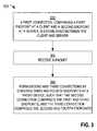
- FIG. 3depicts a flow diagram 300 that illustrates an overview of one embodiment of a method for “proxying” a client-to-server connection.
- the proxyingis “delayed” in the sense that the originally established client-to-server connection is not proxied at the time that the connection is established; the proxying is “delayed” until after the client-to-server connection has been established, but no particular amount of time delay is required.
- a methodmay be performed by proxy device 102 .
- Other embodimentsmay contain operations additional to the operation depicted in flow diagram 300 .
- a first connectionis established between a client and a server.
- the first connectioncomprises a first endpoint at the client and a second endpoint at the server.
- client 108 Amay establish an original full TCP connection with server 104 A by engaging in a handshake phase as described above with reference to FIG. 2 .
- proxy device 102may receive a packet that client 108 A sent through the TCP endpoint at client 108 A.
- second and third connectionsare formed by creating a third endpoint and a fourth endpoint at the proxy device, such that the second connection comprises the first and third endpoints, and the second connection comprises the second and fourth endpoints.
- proxy device 102may “proxy” the connection by constructing two TCP endpoints at proxy device 102 based on (a) information contained in the packet, and (b) information contained in connection block data structures, as described above.
- the client-to-proxy device connectionthen comprises the client's original TCP endpoint and one of the proxy device's constructed TCP endpoints
- the proxy device-to-server connectionthen comprises the server's original TCP endpoint and the other of the proxy device's constructed TCP endpoints. Both connections are full TCP connections having two TCP endpoints each.
- the proxy technique described aboveis performed in response to the receipt of a packet from a client or a server
- the proxy techniqueis performed in response to other events.
- the proxy techniquemay be performed in response to the modification of a packet's payload.
- the proxy techniquemay be performed in response to the expiration of a timer.
- FIG. 4depicts a flow diagram 400 that illustrates one embodiment of a method for the “delayed” proxying of a connection. For example, such a method may be performed by proxy device 102 . Other embodiments may contain operations additional to the operation depicted in flow diagram 400 .
- TCP connection parameterswhich are being negotiated between a client and a server, are intercepted.
- proxy device 102may intercept TCP connection parameters that client 108 A is negotiating with server 104 A during a handshake phase.
- the TCP connection parametersare modified before being forwarded.
- proxy device 102may modify TCP connection parameters that were proposed by client 108 A, and then forward the modified TCP connection parameters, rather than the originally proposed TCP connection parameters, toward server 104 A. Proxy device 102 may do this so that server 104 A has the opportunity to accept only those of the originally proposed TCP connection parameters that proxy device 102 is capable of supporting.
- intercepted informationis stored in a first connection block data structure.
- the intercepted informationcomprises one or more of the TCP connection parameters agreed upon by the client and server.
- a tuple that identifies the clientalso may be stored in the first connection block data structure; thus, the first connection block corresponds to the client.
- proxy device 102may store, in a first connection block data structure at proxy device 102 , TCP connection parameters including the maximum segment size, the window scale factor, and flags that indicate whether time stamping and selective acknowledgment are to be used in the TCP connection.
- TCP connection parametersare stored because they usually cannot be obtained from any packets communicated outside of the negotiation. TCP connection parameters that can be obtained from packets communicated outside of the negotiation do not need to be stored.
- intercepted informationis stored in a second connection block data structure.
- the intercepted informationcomprises one or more of the TCP connection parameters agreed upon by the client and server.
- a tuple that identifies the serveralso may be stored in the first connection block data structure; thus, the second connection block corresponds to the server.
- proxy device 102may store, in a second connection block data structure at proxy device 102 , the same kind of TCP connection parameters that proxy device 102 stored in the first connection block data structure.
- an associationis established between the first and second connection block data structures.
- proxy device 102may establish this association at proxy device 102 .
- proxy device 102may receive one or more packets that client 108 A sent toward server 104 A through a TCP endpoint at client 108 A.
- the contents of the payload portions of the packets collectivelymay comprise a request, such as an HTTP request.
- two TCP endpointsare created at the proxy device such that one full TCP connection is constructed between the client and the proxy device, and another full TCP connection is constructed between the proxy device and the server, thereby proxying the original client-to-server connection.
- the client-to-proxy device connectioncomprises (a) a new TCP endpoint at the proxy device and (b) the original TCP endpoint at the client.
- the proxy device-to-server connectioncomprises (a) a new TCP endpoint at the proxy device and (b) the original TCP endpoint at the server.
- One of the new TCP endpoints at the proxy deviceis created based on (a) one or more TCP connection parameters contained in at least one of the packets received from the client and (b) the TCP connection parameters stored in the connection block data structure that corresponds to the client.
- proxy device 102may allocate and populate a TCB for the new TCP endpoint based on the maximum segment size, the window scale factor, and flags that proxy device 102 stored in the first connection block data structure in block 404 .
- the TCB for the TCP endpointalso may be populated based on actual sequence numbers indicated in the packets received from client 108 A.
- the other new TCP endpointis created based on (a) one or more TCP connection parameters contained in at least one of the packets received from the client and (b) the TCP connection parameters stored in the connection block data structure that was associated, in block 408 , with the first connection block data structure.
- the new TCP endpointsare constructed without the proxy device negotiating the TCP connection parameters with the client or server. After the new TCP endpoints have been created, control passes to block 414 .
- the proxy devicesends a corresponding TCP ACK packet toward the packet's source. For example, for each packet that proxy device 102 received in block 410 , proxy device 102 may send, through the new TCP endpoint that is at the proxy device's end of the new client-to-proxy device connection, a corresponding TCP ACK packet. As a result, client 108 A does not need to receive TCP ACK packets from server 104 A.
- proxy device 102may reorder and assemble the contents of multiple packets to form a message collectively contained therein (such as an HTTP request), determine whether any of the contents of the message match a specified pattern, and then perform specified actions (such as modifying or dropping the packets) in response to a determination that some of the contents match the specified pattern.
- packets that have not been droppedare sent through the new TCP endpoint that is at the proxy device's end of the new proxy device-to-server connection.
- proxy device 102may send, through the new TCP endpoint, the (possibly modified) packets that proxy device 102 received from client 108 A. As a result, the packets are sent toward server 104 A.
- proxy device 102may listen for a corresponding TCP ACK packet from server 104 A. If a specified amount of time passes before proxy device 102 receives a TCP ACK packet for a particular packet, then proxy device 102 may re-send the particular packet to server 104 A. Thus, proxy device 102 may ensure that any packets whose payload portions proxy device 102 modified are reliably transported.
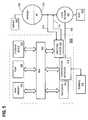
- FIG. 5is a block diagram that illustrates a computer system 500 upon which an embodiment of the invention may be implemented.
- One embodimentis implemented using one or more computer programs running on a network element such as a proxy device.
- the computer system 500is a proxy device such as a firewall device.
- Computer system 500includes a bus 502 or other communication mechanism for communicating information, and a processor 504 coupled with bus 502 for processing information.
- Computer system 500also includes a main memory 506 , such as a random access memory (RAM), flash memory, or other dynamic storage device, coupled to bus 502 for storing information and instructions to be executed by processor 504 .
- Main memory 506also may be used for storing temporary variables or other intermediate information during execution of instructions to be executed by processor 504 .
- Computer system 500further includes a read only memory (ROM) 508 or other static storage device coupled to bus 502 for storing static information and instructions for processor 504 .
- a storage device 510such as a magnetic disk, flash memory or optical disk, is provided and coupled to bus 502 for storing information and instructions.
- a communication interface 518may be coupled to bus 502 for communicating information and command selections to processor 504 .
- Interface 518is a conventional serial interface such as an RS-232 or RS-322 interface.
- An external terminal 512 or other computer systemconnects to the computer system 500 and provides commands to it using the interface 514 .
- Firmware or software running in the computer system 500provides a terminal interface or character-based command interface so that external commands can be given to the computer system.
- a switching system 516is coupled to bus 502 and has an input interface 514 and an output interface 519 to one or more external network elements.
- the external network elementsmay include a local network 522 coupled to one or more hosts 524 , or a global network such as Internet 528 having one or more servers 530 .
- the switching system 516switches information traffic arriving on input interface 514 to output interface 519 according to pre-determined protocols and conventions that are well known. For example, switching system 516 , in cooperation with processor 504 , can determine a destination of a packet of data arriving on input interface 514 and send it to the correct destination using output interface 519 .
- the destinationsmay include host 524 , server 530 , other end stations, or other routing and switching devices in local network 522 or Internet 528 .
- the inventionis related to the use of computer system 500 for proxying an established client-to-server connection on computer system 500 .
- computer system 500provides for such proxying in response to processor 504 executing one or more sequences of one or more instructions contained in main memory 506 .
- Such instructionsmay be read into main memory 506 from another computer-readable Medium, such as storage device 510 .
- Execution of the sequences of instructions contained in main memory 506causes processor 504 to perform the process steps described herein.
- processors in a multi-processing arrangementmay also be employed to execute the sequences of instructions contained in main memory 506 .
- hard-wired circuitrymay be used in place of or in combination with software instructions to implement the invention.
- embodiments of the inventionare not limited to any specific combination of hardware circuitry and software.
- Non-volatile mediaincludes, for example, optical or magnetic disks, such as storage device 510 .
- Volatile mediaincludes dynamic memory, such as main memory 506 .
- Transmission mediaincludes coaxial cables, copper wire and fiber optics, including the wires that comprise bus 502 . Transmission media can also take the form of acoustic or light waves, such as those generated during radio wave and infrared data communications.
- Computer-readable mediainclude, for example, a floppy disk, a flexible disk, hard disk, magnetic tape, or any other magnetic medium, a CD-ROM, any other optical medium, punch cards, paper tape, any other physical medium with patterns of holes, a RAM, a PROM, and EPROM, a FLASH-EPROM, any other memory chip or cartridge, a carrier wave as described hereinafter, or any other medium from which a computer can read.
- Various forms of computer readable mediamay be involved in carrying one or more sequences of one or more instructions to processor 504 for execution.
- the instructionsmay initially be carried on a magnetic disk of a remote computer.
- the remote computercan load the instructions into its dynamic memory and send the instructions over a telephone line using a modem.
- a modem local to computer system 500can receive the data on the telephone line and use an infrared transmitter to convert the data to an infrared signal.
- An infrared detector coupled to bus 502can receive the data carried in the infrared signal and place the data on bus 502 .
- Bus 502carries the data to main memory 506 , from which processor 504 retrieves and executes the instructions.
- the instructions received by main memory 506may optionally be stored on storage device 510 either before or after execution by processor 504 .
- Communication interface 518also provides a two-way data communication coupling to a network link 520 that is connected to a local network 522 .
- communication interface 518may be an integrated services digital network (ISDN) card or a modem to provide a data communication connection to a corresponding type of telephone line.
- ISDNintegrated services digital network
- communication interface 518may be a local area network (LAN) card to provide a data communication connection to a compatible LAN.
- LANlocal area network
- Wireless linksmay also be implemented.
- communication interface 518sends and receives electrical, electromagnetic or optical signals that carry digital data streams representing various types of information.
- Network link 520typically provides data communication through one or more networks to other data devices.
- network link 520may provide a connection through local network 522 to a host computer 524 or to data equipment operated by an Internet Service Provider (ISP) 526 .
- ISP 526in turn provides data communication services through the worldwide packet data communication network now commonly referred to as the “Internet” 528 .
- Internet 528uses electrical, electromagnetic or optical signals that carry digital data streams.
- the signals through the various networks and the signals on network link 520 and through communication interface 518which carry the digital data to and from computer system 500 , are exemplary forms of carrier waves transporting the information.
- TCP connection parametersmay be obtained from a TCP SYN packet.
Landscapes
- Engineering & Computer Science (AREA)
- Computer Security & Cryptography (AREA)
- Computer Networks & Wireless Communication (AREA)
- Signal Processing (AREA)
- Data Exchanges In Wide-Area Networks (AREA)
Abstract
Description
- 1.0 General Overview
- 2.0 Structural and Functional Overview
- 2.1 System
- 2.2 Client-Server Three Way Handshake
- 2.3 “Delayed” Proxying Technique
- 3.0 Implementation Examples
- 4.0 Implementation Mechanisms—Hardware Overview
- 5.0 Extensions and Alternatives
1.0 General Overview
Claims (20)
Priority Applications (1)
| Application Number | Priority Date | Filing Date | Title |
|---|---|---|---|
| US11/061,248US9118717B2 (en) | 2005-02-18 | 2005-02-18 | Delayed network protocol proxy for packet inspection in a network |
Applications Claiming Priority (1)
| Application Number | Priority Date | Filing Date | Title |
|---|---|---|---|
| US11/061,248US9118717B2 (en) | 2005-02-18 | 2005-02-18 | Delayed network protocol proxy for packet inspection in a network |
Publications (2)
| Publication Number | Publication Date |
|---|---|
| US20060190612A1 US20060190612A1 (en) | 2006-08-24 |
| US9118717B2true US9118717B2 (en) | 2015-08-25 |
Family
ID=36914148
Family Applications (1)
| Application Number | Title | Priority Date | Filing Date |
|---|---|---|---|
| US11/061,248Expired - Fee RelatedUS9118717B2 (en) | 2005-02-18 | 2005-02-18 | Delayed network protocol proxy for packet inspection in a network |
Country Status (1)
| Country | Link |
|---|---|
| US (1) | US9118717B2 (en) |
Cited By (1)
| Publication number | Priority date | Publication date | Assignee | Title |
|---|---|---|---|---|
| US20160094686A1 (en)* | 2014-09-26 | 2016-03-31 | Canon Kabushiki Kaisha | Communication apparatus, communication system, information processing method, and storage medium |
Families Citing this family (27)
| Publication number | Priority date | Publication date | Assignee | Title |
|---|---|---|---|---|
| US8473620B2 (en)* | 2003-04-14 | 2013-06-25 | Riverbed Technology, Inc. | Interception of a cloud-based communication connection |
| US8224966B2 (en) | 2004-08-24 | 2012-07-17 | Cisco Technology, Inc. | Reproxying an unproxied connection |
| US8613071B2 (en)* | 2005-08-10 | 2013-12-17 | Riverbed Technology, Inc. | Split termination for secure communication protocols |
| US8478986B2 (en)* | 2005-08-10 | 2013-07-02 | Riverbed Technology, Inc. | Reducing latency of split-terminated secure communication protocol sessions |
| US8438628B2 (en)* | 2005-08-10 | 2013-05-07 | Riverbed Technology, Inc. | Method and apparatus for split-terminating a secure network connection, with client authentication |
| US8782393B1 (en) | 2006-03-23 | 2014-07-15 | F5 Networks, Inc. | Accessing SSL connection data by a third-party |
| US20080107124A1 (en)* | 2006-11-06 | 2008-05-08 | Jordi Ros-Giralt | System and method for supporting mobility and multipath packet delivery in ip communications and computer networks across nat and firewall boxes |
| US7743160B2 (en)* | 2007-03-29 | 2010-06-22 | Blue Coat Systems, Inc. | System and method of delaying connection acceptance to support connection request processing at layer-7 |
| US9100319B2 (en) | 2007-08-10 | 2015-08-04 | Fortinet, Inc. | Context-aware pattern matching accelerator |
| US8526306B2 (en)* | 2008-12-05 | 2013-09-03 | Cloudshield Technologies, Inc. | Identification of patterns in stateful transactions |
| US8707043B2 (en)* | 2009-03-03 | 2014-04-22 | Riverbed Technology, Inc. | Split termination of secure communication sessions with mutual certificate-based authentication |
| US9059968B2 (en)* | 2009-11-06 | 2015-06-16 | Telefonaktiebolaget L M Ericsson (Publ) | Stateless transmission control protocol rendezvous solution for border gateway function |
| US8700892B2 (en) | 2010-03-19 | 2014-04-15 | F5 Networks, Inc. | Proxy SSL authentication in split SSL for client-side proxy agent resources with content insertion |
| US9998545B2 (en)* | 2011-04-02 | 2018-06-12 | Open Invention Network, Llc | System and method for improved handshake protocol |
| US9935879B2 (en)* | 2012-12-29 | 2018-04-03 | Netronome Systems, Inc. | Efficient intercept of connection-based transport layer connections |
| US20140281018A1 (en)* | 2013-03-13 | 2014-09-18 | Futurewei Technologies, Inc. | Dynamic Optimization of TCP Connections |
| US9237129B2 (en) | 2014-05-13 | 2016-01-12 | Dell Software Inc. | Method to enable deep packet inspection (DPI) in openflow-based software defined network (SDN) |
| US10628186B2 (en) | 2014-09-08 | 2020-04-21 | Wirepath Home Systems, Llc | Method for electronic device virtualization and management |
| US9537872B2 (en) | 2014-12-31 | 2017-01-03 | Dell Software Inc. | Secure neighbor discovery (SEND) using pre-shared key |
| US9998425B2 (en)* | 2015-01-27 | 2018-06-12 | Sonicwall Inc. | Dynamic bypass of TLS connections matching exclusion list in DPI-SSL in a NAT deployment |
| US10432406B1 (en)* | 2015-12-22 | 2019-10-01 | F5 Networks, Inc. | Cipher rule feedback |
| US10805432B2 (en)* | 2016-10-12 | 2020-10-13 | Nec Corporation | Method and system for acceleration of TCP connection establishment |
| US10812468B2 (en)* | 2017-12-07 | 2020-10-20 | Sonicwall Inc. | Dynamic bypass |
| US11057501B2 (en)* | 2018-12-31 | 2021-07-06 | Fortinet, Inc. | Increasing throughput density of TCP traffic on a hybrid data network having both wired and wireless connections by modifying TCP layer behavior over the wireless connection while maintaining TCP protocol |
| US11336549B2 (en)* | 2020-01-15 | 2022-05-17 | Cisco Technology, Inc. | Systems and methods for dynamically optimizing TCP flow in WAN networks |
| US11722412B1 (en)* | 2020-09-28 | 2023-08-08 | Amazon Technologies, Inc. | Dynamically managing connection parameters among multiple computing devices |
| US11533372B2 (en)* | 2021-03-31 | 2022-12-20 | Google Llc | Proxyless protocol |
Citations (44)
| Publication number | Priority date | Publication date | Assignee | Title |
|---|---|---|---|---|
| US5937169A (en) | 1997-10-29 | 1999-08-10 | 3Com Corporation | Offload of TCP segmentation to a smart adapter |
| US5941988A (en) | 1997-01-27 | 1999-08-24 | International Business Machines Corporation | Session and transport layer proxies via TCP glue |
| US5961605A (en) | 1997-02-06 | 1999-10-05 | Gte Laboratories Incorporated | Method and apparatus for acknowledging TCP data packets |
| US5978849A (en)* | 1997-06-13 | 1999-11-02 | International Business Machines Corporation | Systems, methods, and computer program products for establishing TCP connections using information from closed TCP connections in time-wait state |
| US6006268A (en) | 1997-07-31 | 1999-12-21 | Cisco Technology, Inc. | Method and apparatus for reducing overhead on a proxied connection |
| US6098093A (en) | 1998-03-19 | 2000-08-01 | International Business Machines Corp. | Maintaining sessions in a clustered server environment |
| US6173322B1 (en) | 1997-06-05 | 2001-01-09 | Silicon Graphics, Inc. | Network request distribution based on static rules and dynamic performance data |
| US6338089B1 (en) | 1998-10-06 | 2002-01-08 | Bull Hn Information Systems Inc. | Method and system for providing session pools for high performance web browser and server communications |
| US6389462B1 (en)* | 1998-12-16 | 2002-05-14 | Lucent Technologies Inc. | Method and apparatus for transparently directing requests for web objects to proxy caches |
| US6411986B1 (en) | 1998-11-10 | 2002-06-25 | Netscaler, Inc. | Internet client-server multiplexer |
| US20020085549A1 (en) | 2000-12-28 | 2002-07-04 | Reza Ahmed Areef | Application-level mobility support in communications network |
| US20020091738A1 (en) | 2000-06-12 | 2002-07-11 | Rohrabaugh Gary B. | Resolution independent vector display of internet content |
| US20020112152A1 (en) | 2001-02-12 | 2002-08-15 | Vanheyningen Marc D. | Method and apparatus for providing secure streaming data transmission facilities using unreliable protocols |
| US20020143954A1 (en)* | 2001-04-03 | 2002-10-03 | Aiken John Andrew | Methods, systems and computer program products for content-based routing via active TCP connection transfer |
| US20020188743A1 (en) | 2001-06-12 | 2002-12-12 | Daniel Schaffrath | Method for an improved interworking of a user application and a server |
| US20020199114A1 (en)* | 2001-01-11 | 2002-12-26 | Elliot Schwartz | Method and apparatus for firewall traversal |
| US20030028666A1 (en)* | 2001-07-17 | 2003-02-06 | Hanner Brian D. | System and method for virtual packet reassembly |
| US20030041095A1 (en) | 2001-08-10 | 2003-02-27 | Konda Suresh L. | Method and system for data transformation in a heterogeneous computer system |
| US20030120811A1 (en)* | 1998-10-09 | 2003-06-26 | Netmotion Wireless, Inc. | Method and apparatus for providing mobile and other intermittent connectivity in a computing environment |
| US20030123481A1 (en)* | 2001-11-13 | 2003-07-03 | Ems Technologies, Inc. | Enhancements for TCP performance enhancing proxies |
| US6615265B1 (en) | 1998-08-04 | 2003-09-02 | International Business Machines Corporation | Enabling planned outages of application servers |
| US20030172169A1 (en)* | 2002-03-07 | 2003-09-11 | Cheng Charles T. | Method and apparatus for caching protocol processing data |
| US20040006625A1 (en) | 2002-05-10 | 2004-01-08 | Oracle International Corporation | Method and mechanism for implementing dynamic sizing of session pools |
| US6725281B1 (en) | 1999-06-11 | 2004-04-20 | Microsoft Corporation | Synchronization of controlled device state using state table and eventing in data-driven remote device control model |
| US20040088413A1 (en) | 2002-11-04 | 2004-05-06 | Bhogi Sankara R. | Dynamically configurable resource pool |
| US6775692B1 (en) | 1997-07-31 | 2004-08-10 | Cisco Technology, Inc. | Proxying and unproxying a connection using a forwarding agent |
| US6801927B1 (en) | 1999-09-24 | 2004-10-05 | Akamba Corporation | Network adaptor card with reverse proxy and cache and method implemented therewith |
| US20040205644A1 (en) | 2000-12-29 | 2004-10-14 | International Business Machines Corporation | Method and system for allowing in place editing of office documents in a place |
| US20050015356A1 (en) | 2003-07-17 | 2005-01-20 | Sybase, Inc. | Database System Providing Methodology for Prepared Statement Cloning |
| US6857009B1 (en) | 1999-10-22 | 2005-02-15 | Nomadix, Inc. | System and method for network access without reconfiguration |
| US20050060372A1 (en) | 2003-08-27 | 2005-03-17 | Debettencourt Jason | Techniques for filtering data from a data stream of a web services application |
| US20050076126A1 (en) | 2003-10-06 | 2005-04-07 | International Business Machines Corporation | Tunneling non-HTTP traffic through a reverse proxy |
| US6892230B1 (en) | 1999-06-11 | 2005-05-10 | Microsoft Corporation | Dynamic self-configuration for ad hoc peer networking using mark-up language formated description messages |
| US20050120117A1 (en) | 2003-11-26 | 2005-06-02 | International Business Machines Corporation | Efficient connection pool validation |
| US20050149940A1 (en) | 2003-12-31 | 2005-07-07 | Sychron Inc. | System Providing Methodology for Policy-Based Resource Allocation |
| US20050172029A1 (en) | 2004-01-29 | 2005-08-04 | International Business Machines Corporation | Method and apparatus for managing a connection pool using heuristic information |
| US20050198261A1 (en)* | 2004-01-08 | 2005-09-08 | Naresh Durvasula | Proxy architecture for providing quality of service(QoS) reservations |
| US6968389B1 (en) | 2001-07-17 | 2005-11-22 | Cisco Technology, Inc. | System and method for qualifying requests in a network |
| US20060031571A1 (en) | 2004-04-29 | 2006-02-09 | International Business Machines Corporation | Data communications through a split connection proxy |
| US20060031520A1 (en) | 2004-05-06 | 2006-02-09 | Motorola, Inc. | Allocation of common persistent connections through proxies |
| US20060168224A1 (en) | 2002-09-07 | 2006-07-27 | Midgley Nicholas J | Remote dynamic configuration of a web server to facilitate capacity on demand |
| US7085814B1 (en) | 1999-06-11 | 2006-08-01 | Microsoft Corporation | Data driven remote device control model with general programming interface-to-network messaging adapter |
| US20060282662A1 (en) | 2005-06-13 | 2006-12-14 | Iamsecureonline, Inc. | Proxy authentication network |
| US7406709B2 (en)* | 2002-09-09 | 2008-07-29 | Audiocodes, Inc. | Apparatus and method for allowing peer-to-peer network traffic across enterprise firewalls |
- 2005
- 2005-02-18USUS11/061,248patent/US9118717B2/ennot_activeExpired - Fee Related
Patent Citations (49)
| Publication number | Priority date | Publication date | Assignee | Title |
|---|---|---|---|---|
| US5941988A (en) | 1997-01-27 | 1999-08-24 | International Business Machines Corporation | Session and transport layer proxies via TCP glue |
| US5961605A (en) | 1997-02-06 | 1999-10-05 | Gte Laboratories Incorporated | Method and apparatus for acknowledging TCP data packets |
| US6173322B1 (en) | 1997-06-05 | 2001-01-09 | Silicon Graphics, Inc. | Network request distribution based on static rules and dynamic performance data |
| US5978849A (en)* | 1997-06-13 | 1999-11-02 | International Business Machines Corporation | Systems, methods, and computer program products for establishing TCP connections using information from closed TCP connections in time-wait state |
| US6598081B1 (en)* | 1997-07-31 | 2003-07-22 | Cisco Technology, Inc. | Method and apparatus for eliminating use of a transfer protocol on a proxied connection |
| US6006268A (en) | 1997-07-31 | 1999-12-21 | Cisco Technology, Inc. | Method and apparatus for reducing overhead on a proxied connection |
| US6298380B1 (en) | 1997-07-31 | 2001-10-02 | Cisco Technology, Inc. | Method and apparatus for reducing overhead on a proxied connection |
| US6775692B1 (en) | 1997-07-31 | 2004-08-10 | Cisco Technology, Inc. | Proxying and unproxying a connection using a forwarding agent |
| US5937169A (en) | 1997-10-29 | 1999-08-10 | 3Com Corporation | Offload of TCP segmentation to a smart adapter |
| US6098093A (en) | 1998-03-19 | 2000-08-01 | International Business Machines Corp. | Maintaining sessions in a clustered server environment |
| US6615265B1 (en) | 1998-08-04 | 2003-09-02 | International Business Machines Corporation | Enabling planned outages of application servers |
| US6338089B1 (en) | 1998-10-06 | 2002-01-08 | Bull Hn Information Systems Inc. | Method and system for providing session pools for high performance web browser and server communications |
| US20030120811A1 (en)* | 1998-10-09 | 2003-06-26 | Netmotion Wireless, Inc. | Method and apparatus for providing mobile and other intermittent connectivity in a computing environment |
| US6411986B1 (en) | 1998-11-10 | 2002-06-25 | Netscaler, Inc. | Internet client-server multiplexer |
| US6389462B1 (en)* | 1998-12-16 | 2002-05-14 | Lucent Technologies Inc. | Method and apparatus for transparently directing requests for web objects to proxy caches |
| US6892230B1 (en) | 1999-06-11 | 2005-05-10 | Microsoft Corporation | Dynamic self-configuration for ad hoc peer networking using mark-up language formated description messages |
| US6725281B1 (en) | 1999-06-11 | 2004-04-20 | Microsoft Corporation | Synchronization of controlled device state using state table and eventing in data-driven remote device control model |
| US6779004B1 (en) | 1999-06-11 | 2004-08-17 | Microsoft Corporation | Auto-configuring of peripheral on host/peripheral computing platform with peer networking-to-host/peripheral adapter for peer networking connectivity |
| US7085814B1 (en) | 1999-06-11 | 2006-08-01 | Microsoft Corporation | Data driven remote device control model with general programming interface-to-network messaging adapter |
| US6801927B1 (en) | 1999-09-24 | 2004-10-05 | Akamba Corporation | Network adaptor card with reverse proxy and cache and method implemented therewith |
| US6857009B1 (en) | 1999-10-22 | 2005-02-15 | Nomadix, Inc. | System and method for network access without reconfiguration |
| US20020091738A1 (en) | 2000-06-12 | 2002-07-11 | Rohrabaugh Gary B. | Resolution independent vector display of internet content |
| US20020085549A1 (en) | 2000-12-28 | 2002-07-04 | Reza Ahmed Areef | Application-level mobility support in communications network |
| US20040205644A1 (en) | 2000-12-29 | 2004-10-14 | International Business Machines Corporation | Method and system for allowing in place editing of office documents in a place |
| US20020199114A1 (en)* | 2001-01-11 | 2002-12-26 | Elliot Schwartz | Method and apparatus for firewall traversal |
| US20020112152A1 (en) | 2001-02-12 | 2002-08-15 | Vanheyningen Marc D. | Method and apparatus for providing secure streaming data transmission facilities using unreliable protocols |
| US20020143954A1 (en)* | 2001-04-03 | 2002-10-03 | Aiken John Andrew | Methods, systems and computer program products for content-based routing via active TCP connection transfer |
| US20020188743A1 (en) | 2001-06-12 | 2002-12-12 | Daniel Schaffrath | Method for an improved interworking of a user application and a server |
| US20030028666A1 (en)* | 2001-07-17 | 2003-02-06 | Hanner Brian D. | System and method for virtual packet reassembly |
| US6968389B1 (en) | 2001-07-17 | 2005-11-22 | Cisco Technology, Inc. | System and method for qualifying requests in a network |
| US20030041095A1 (en) | 2001-08-10 | 2003-02-27 | Konda Suresh L. | Method and system for data transformation in a heterogeneous computer system |
| US20030123481A1 (en)* | 2001-11-13 | 2003-07-03 | Ems Technologies, Inc. | Enhancements for TCP performance enhancing proxies |
| US6975647B2 (en) | 2001-11-13 | 2005-12-13 | Ems Technologies Canada, Ltd | Enhancements for TCP performance enhancing proxies |
| US20030172169A1 (en)* | 2002-03-07 | 2003-09-11 | Cheng Charles T. | Method and apparatus for caching protocol processing data |
| US20040006625A1 (en) | 2002-05-10 | 2004-01-08 | Oracle International Corporation | Method and mechanism for implementing dynamic sizing of session pools |
| US7337226B2 (en) | 2002-05-10 | 2008-02-26 | Oracle International Corporation | Method and mechanism for implementing dynamic sizing of session pools |
| US20060168224A1 (en) | 2002-09-07 | 2006-07-27 | Midgley Nicholas J | Remote dynamic configuration of a web server to facilitate capacity on demand |
| US7406709B2 (en)* | 2002-09-09 | 2008-07-29 | Audiocodes, Inc. | Apparatus and method for allowing peer-to-peer network traffic across enterprise firewalls |
| US20040088413A1 (en) | 2002-11-04 | 2004-05-06 | Bhogi Sankara R. | Dynamically configurable resource pool |
| US20050015356A1 (en) | 2003-07-17 | 2005-01-20 | Sybase, Inc. | Database System Providing Methodology for Prepared Statement Cloning |
| US20050060372A1 (en) | 2003-08-27 | 2005-03-17 | Debettencourt Jason | Techniques for filtering data from a data stream of a web services application |
| US20050076126A1 (en) | 2003-10-06 | 2005-04-07 | International Business Machines Corporation | Tunneling non-HTTP traffic through a reverse proxy |
| US20050120117A1 (en) | 2003-11-26 | 2005-06-02 | International Business Machines Corporation | Efficient connection pool validation |
| US20050149940A1 (en) | 2003-12-31 | 2005-07-07 | Sychron Inc. | System Providing Methodology for Policy-Based Resource Allocation |
| US20050198261A1 (en)* | 2004-01-08 | 2005-09-08 | Naresh Durvasula | Proxy architecture for providing quality of service(QoS) reservations |
| US20050172029A1 (en) | 2004-01-29 | 2005-08-04 | International Business Machines Corporation | Method and apparatus for managing a connection pool using heuristic information |
| US20060031571A1 (en) | 2004-04-29 | 2006-02-09 | International Business Machines Corporation | Data communications through a split connection proxy |
| US20060031520A1 (en) | 2004-05-06 | 2006-02-09 | Motorola, Inc. | Allocation of common persistent connections through proxies |
| US20060282662A1 (en) | 2005-06-13 | 2006-12-14 | Iamsecureonline, Inc. | Proxy authentication network |
Non-Patent Citations (12)
| Title |
|---|
| Berners, T et al. "Hypertext Transfer Protocol-HTTP/1.0", HTTP /1.0, May 1996, http://www.ietf.org/rfc/rfc1945.txt, pp. 1-60. (referenced located on CD ROM). |
| Egevang, K. et al., "The IP Network Address Translator (NAT)", Network Address Translator, May 1994, http://www.ietf.org/rfc/rfc1631.txt, pp. 1-10. (referenced located on CD ROM). |
| Fielding, R. et al. "Hypertext Transfer Protocol-HTTP/1.1", HTTP /1.1, Jan. 1997, http://www.ietf.org/rfc/rfc2068.txt, pp. 1-162. (referenced located on CD ROM). |
| Fielding, R. et al., "Hypertext Transfer Protocol-HTPP/1.1," The Internet Society, Jun. 1999, http://www.ietf.org/rfc/rfc2616.txt, pp. 1-176. (referenced located on CD ROM). |
| Information Sciences Institute, "DOD Standard Internet Protocol", Internet Protocol, Jan. 1980, http://www.ietf.org/rfc/rfc0760.txt, pp. 1-42. (referenced located on CD ROM). |
| Information Sciences Institute, "Transmission Control Protocol DARPA Internet Program Protocol Specification", Transmission Control Protocol, Sep. 1981, http://www.ietf.org/rfc/rfc0793.txt, pp. 1-85. (referenced located on CD ROM). |
| Information Sciences Institute, DOD Standard Transmission Control Protocol, Jan. 1980, http://www.ietf.org/rfc/rfc0761.txt, pp. 1-84. (referenced located on CD ROM). |
| Khare, R. et al. "Upgrading to TLS Within HTTP/1.1", HTTP Upgrade to TLS, May 2002, http://www.ietf.org/rfc/rfc2817.txt, pp. 1-13. (reference located on CD ROM. |
| Postel, J., "Internet Control Message Protocol DARPA Internet Program Protocol Specification", Sep. 1981, http://www.ietf.org/rfc/rfc0777.txt, pp. 1-21. (referenced located on CD ROM). |
| Postel, J., "Internet Control Message Protocol", Apr. 1981, http://www.ietf.org/rfc/rfc0777.txt, pp. 1-14. (referenced located on CD ROM). |
| Ramakrishnan, K. et al., "The Addition of Explicit Congestion Notification (ECN) to IP Status of this Memo)", The Internet Society, Sep. 2001, http://www.ietf.org/rfc/rfc3168.txt, pp. 1-63. (referenced located on CD ROM). |
| Srisuresh, P.et al., "Traditional IP Network Address Translator (Translator NAT)", Traditional NAT, Jan. 2001, http://www.ietf.org/rfc/rfc3022.txt, pp. 1-16. (referenced located on CD ROM). |
Cited By (2)
| Publication number | Priority date | Publication date | Assignee | Title |
|---|---|---|---|---|
| US20160094686A1 (en)* | 2014-09-26 | 2016-03-31 | Canon Kabushiki Kaisha | Communication apparatus, communication system, information processing method, and storage medium |
| US10506080B2 (en)* | 2014-09-26 | 2019-12-10 | Canon Kabushiki Kaisha | Communication apparatus, communication system, information processing method, and storage medium |
Also Published As
| Publication number | Publication date |
|---|---|
| US20060190612A1 (en) | 2006-08-24 |
Similar Documents
| Publication | Publication Date | Title |
|---|---|---|
| US9118717B2 (en) | Delayed network protocol proxy for packet inspection in a network | |
| US8224966B2 (en) | Reproxying an unproxied connection | |
| US10432522B2 (en) | Network packet flow controller with extended session management | |
| US9973387B1 (en) | System and method of traffic inspection and stateful connection forwarding among geographically dispersed network alliances organized as clusters | |
| US10505838B2 (en) | System and method for diverting established communication sessions | |
| US7826487B1 (en) | Coalescing acknowledgement responses to improve network communications | |
| US7277963B2 (en) | TCP proxy providing application layer modifications | |
| US9154512B2 (en) | Transparently proxying transport protocol connections using an external server | |
| US8335858B2 (en) | Transparent auto-discovery of network devices logically located between a client and server | |
| EP3577877B1 (en) | Methods and systems for enhanced support of tcp options in a tcp spoofed system | |
| US20140211813A1 (en) | Unobtrusive content compression in a telecommunications network | |
| WO2011020397A1 (en) | Network proxy implementation method and apparatus | |
| WO2021063147A1 (en) | Packet forwarding method and apparatus for heterogeneous network | |
| CA2950453C (en) | Proxy node for transferring packets between a server and a client using port sharding | |
| US20150373135A1 (en) | Wide area network optimization | |
| US8181060B1 (en) | Preventing data corruption with transparent network connections | |
| US10361997B2 (en) | Auto discovery between proxies in an IPv6 network | |
| CN105791239A (en) | A TCP middleman processing method | |
| CA2874047C (en) | System and method for diverting established communication sessions | |
| CN118802454A (en) | Abnormal website identification method, device, terminal equipment and storage medium | |
| FI111890B (en) | Procedure for optimizing network traffic |
Legal Events
| Date | Code | Title | Description |
|---|---|---|---|
| AS | Assignment | Owner name:CISCO TECHNOLOGY, INC., CALIFORNIA Free format text:ASSIGNMENT OF ASSIGNORS INTEREST;ASSIGNORS:KAHOL, ANURAG;MAJEE, SUMANDRA;WATERMAN, ALEX;AND OTHERS;REEL/FRAME:016312/0140 Effective date:20050216 Owner name:CISCO TECHNOLOGY INC., CALIFORNIA Free format text:ASSIGNMENT OF ASSIGNORS INTEREST;ASSIGNORS:KAHOL, ANURAG;MAJEE, SUMANDRA;WATERMAN, ALEX;AND OTHERS;REEL/FRAME:016312/0140 Effective date:20050216 | |
| ZAAA | Notice of allowance and fees due | Free format text:ORIGINAL CODE: NOA | |
| ZAAB | Notice of allowance mailed | Free format text:ORIGINAL CODE: MN/=. | |
| STCF | Information on status: patent grant | Free format text:PATENTED CASE | |
| MAFP | Maintenance fee payment | Free format text:PAYMENT OF MAINTENANCE FEE, 4TH YEAR, LARGE ENTITY (ORIGINAL EVENT CODE: M1551); ENTITY STATUS OF PATENT OWNER: LARGE ENTITY Year of fee payment:4 | |
| FEPP | Fee payment procedure | Free format text:MAINTENANCE FEE REMINDER MAILED (ORIGINAL EVENT CODE: REM.); ENTITY STATUS OF PATENT OWNER: LARGE ENTITY | |
| LAPS | Lapse for failure to pay maintenance fees | Free format text:PATENT EXPIRED FOR FAILURE TO PAY MAINTENANCE FEES (ORIGINAL EVENT CODE: EXP.); ENTITY STATUS OF PATENT OWNER: LARGE ENTITY | |
| STCH | Information on status: patent discontinuation | Free format text:PATENT EXPIRED DUE TO NONPAYMENT OF MAINTENANCE FEES UNDER 37 CFR 1.362 | |
| FP | Lapsed due to failure to pay maintenance fee | Effective date:20230825 |