US9116233B2 - Power mode control for sensors - Google Patents
Power mode control for sensorsDownload PDFInfo
- Publication number
- US9116233B2 US9116233B2US13/545,717US201213545717AUS9116233B2US 9116233 B2US9116233 B2US 9116233B2US 201213545717 AUS201213545717 AUS 201213545717AUS 9116233 B2US9116233 B2US 9116233B2
- Authority
- US
- United States
- Prior art keywords
- positioning signal
- area
- signal
- positioning
- vehicle
- Prior art date
- Legal status (The legal status is an assumption and is not a legal conclusion. Google has not performed a legal analysis and makes no representation as to the accuracy of the status listed.)
- Active, expires
Links
Images


Classifications
- G—PHYSICS
- G01—MEASURING; TESTING
- G01S—RADIO DIRECTION-FINDING; RADIO NAVIGATION; DETERMINING DISTANCE OR VELOCITY BY USE OF RADIO WAVES; LOCATING OR PRESENCE-DETECTING BY USE OF THE REFLECTION OR RERADIATION OF RADIO WAVES; ANALOGOUS ARRANGEMENTS USING OTHER WAVES
- G01S19/00—Satellite radio beacon positioning systems; Determining position, velocity or attitude using signals transmitted by such systems
- G01S19/01—Satellite radio beacon positioning systems transmitting time-stamped messages, e.g. GPS [Global Positioning System], GLONASS [Global Orbiting Navigation Satellite System] or GALILEO
- G01S19/13—Receivers
- G—PHYSICS
- G01—MEASURING; TESTING
- G01S—RADIO DIRECTION-FINDING; RADIO NAVIGATION; DETERMINING DISTANCE OR VELOCITY BY USE OF RADIO WAVES; LOCATING OR PRESENCE-DETECTING BY USE OF THE REFLECTION OR RERADIATION OF RADIO WAVES; ANALOGOUS ARRANGEMENTS USING OTHER WAVES
- G01S19/00—Satellite radio beacon positioning systems; Determining position, velocity or attitude using signals transmitted by such systems
- G01S19/38—Determining a navigation solution using signals transmitted by a satellite radio beacon positioning system
- G01S19/39—Determining a navigation solution using signals transmitted by a satellite radio beacon positioning system the satellite radio beacon positioning system transmitting time-stamped messages, e.g. GPS [Global Positioning System], GLONASS [Global Orbiting Navigation Satellite System] or GALILEO
- G01S19/42—Determining position
- G—PHYSICS
- G01—MEASURING; TESTING
- G01S—RADIO DIRECTION-FINDING; RADIO NAVIGATION; DETERMINING DISTANCE OR VELOCITY BY USE OF RADIO WAVES; LOCATING OR PRESENCE-DETECTING BY USE OF THE REFLECTION OR RERADIATION OF RADIO WAVES; ANALOGOUS ARRANGEMENTS USING OTHER WAVES
- G01S19/00—Satellite radio beacon positioning systems; Determining position, velocity or attitude using signals transmitted by such systems
- G01S19/01—Satellite radio beacon positioning systems transmitting time-stamped messages, e.g. GPS [Global Positioning System], GLONASS [Global Orbiting Navigation Satellite System] or GALILEO
- G01S19/13—Receivers
- G01S19/34—Power consumption
- G—PHYSICS
- G01—MEASURING; TESTING
- G01S—RADIO DIRECTION-FINDING; RADIO NAVIGATION; DETERMINING DISTANCE OR VELOCITY BY USE OF RADIO WAVES; LOCATING OR PRESENCE-DETECTING BY USE OF THE REFLECTION OR RERADIATION OF RADIO WAVES; ANALOGOUS ARRANGEMENTS USING OTHER WAVES
- G01S19/00—Satellite radio beacon positioning systems; Determining position, velocity or attitude using signals transmitted by such systems
- G01S19/38—Determining a navigation solution using signals transmitted by a satellite radio beacon positioning system
- G01S19/39—Determining a navigation solution using signals transmitted by a satellite radio beacon positioning system the satellite radio beacon positioning system transmitting time-stamped messages, e.g. GPS [Global Positioning System], GLONASS [Global Orbiting Navigation Satellite System] or GALILEO
- G01S19/42—Determining position
- G01S19/48—Determining position by combining or switching between position solutions derived from the satellite radio beacon positioning system and position solutions derived from a further system
- G01S19/49—Determining position by combining or switching between position solutions derived from the satellite radio beacon positioning system and position solutions derived from a further system whereby the further system is an inertial position system, e.g. loosely-coupled
Definitions
- the embodiments presented hereingenerally relate to power mode control for sensors in a positioning system.
- Positioning systemssuch as satellite-based Global Positioning System (GPS) are commonly used in vehicles for navigation purposes. However, such positioning systems may consume excessive battery power under certain conditions.
- GPSGlobal Positioning System
- FIG. 1Aillustrates an example satellite-based positioning system.
- FIG. 1Billustrates an exemplary positioning system
- FIG. 2Aillustrates an example heading of a vehicle.
- FIG. 2Billustrates an orientation of a positioning system with respect to a heading of a vehicle.
- FIG. 3Aillustrates an example of a poor signal environment.
- FIGS. 3B-Cillustrate examples of good and poor signal environments.
- FIG. 4illustrates an example positioning system that switches power modes for auxiliary sensors according to an embodiment of the disclosure.
- FIG. 5illustrates an example process illustrating steps performed by a positioning system to provide accurate positioning of a vehicle while conserving power according to an embodiment of the disclosure.
- FIG. 6illustrates is a block diagram of an exemplary computer system on which the embodiments described herein can be implemented.
- a satellite navigation (SAT NAV) systemis a system of satellites that provide autonomous geo-spatial positioning with global coverage.
- a satellite navigation system with global coveragemay be termed a Global Navigation Satellite System (GNSS.)
- the Global Positioning System (GPS)is a part of GNSS and is an example of a SAT NAV system that provides location and time information anywhere on or near the Earth where there is unobstructed line-of-sight access to four or more GPS satellites.
- GPS satellitesare maintained by the United States government and are freely accessible to anyone with a positioning system that can receive GPS signals from the GPS satellites.
- a positioning systemcalculates its position (and therefore by default a position of the vehicle it is in) based on timing signals sent by GPS satellites.
- Each GPS satellitecontinually transmits messages that include the time the message was transmitted and a satellite position at time of message transmission.
- the positioning systemuses the messages it receives to determine the transit time of each message and computes the distance to each satellite. These distances along with the satellites' locations are used with the possible aid of trilateration, to compute the position of the vehicle. This position is then displayed, perhaps with a moving-map display or latitude, longitude and elevation information. Many GPS units show derived information such as direction and speed calculated from position changes.
- positioning systemsmay use four or more satellites to solve for both the positioning system's location and time.
- the accurately computed timeis hidden by most GPS applications, which use only the location. A few specialized GPS applications do however use the time; these include time transfer, traffic signal timing, and synchronization of cellular phone base stations.
- the positioning signalis a satellite-based positioning system.
- the positioning signalmay be any type of signal that help determine a position of vehicle 100 , such as a WiFi or any other signal that can be used for triangulation.
- FIG. 1Aillustrates an example satellite-based positioning system according to an embodiment of the disclosure.
- FIG. 1Aillustrates satellites 104 a - n and a vehicle 100 that includes a positioning system 102 , which may be part of a mobile device (e.g. cellular phone), and/or portable GPS device or other positioning system.
- Positioning system 102may provide a position and heading of vehicle 100 that helps guide vehicle 100 on, for example, a road.
- Satellites 104 a - ntransmit respective positioning signals 106 a - n that are used by positioning system 102 to determine a position of vehicle 100 .
- positioning system 102requires line-of-sight access to positioning signals 106 a - n .
- Line-of-sight accessrefers to an unobstructed path for the signals 106 a - n from satellites 104 to receiver 108 in vehicle 100 .
- the number of satellites “n”is arbitrary.
- An example of positioning system 102is further illustrated in FIG. 1B .
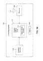
- FIG. 1Billustrates an exemplary positioning system 102 .
- Positioning system 102includes a receiver 108 , antenna 110 , position Kalman filter 112 , signal quality monitor 114 , a battery 120 , and auxiliary sensors 116 .
- Receiver 108is coupled to an antenna 110 and to position Kalman filter 112 .
- Auxiliary sensors 116are coupled to position Kalman filter 112 as well.
- Position Kalman filter 112includes a signal quality monitor 114 .
- receiver 108receives signals 106 from satellites 104 via antenna 110 .
- the signals received by receiver 108are provided to position Kalman filter 112 .
- Position Kalman filter 112determines a position of vehicle 100 based on the received signals 106 .
- Signal quality monitor 114determines a strength of positioning signals 106 and whether line-of-sight access to positioning signals 106 is available.
- FIG. 2Aillustrates an example heading of vehicle 100 .
- vehicle 100is on a road that diverges into three paths: path A, path B, and path C.
- position Kalman filterrelies on positioning signals 106 .
- the heading of vehicle 100is along path B.
- FIG. 2Billustrates an orientation of positioning system 102 with respect to a heading of vehicle 100 .
- an orientation 202 of positioning system 102may not be the same as a heading 200 of vehicle 100 .
- the “orientation” of positioning system 102 as referred to hereinrefers to a direction which positioning system 102 is pointing towards.
- a positioning systemsuch as a portable GPS navigator or a cellular phone-based GPS system mounted on a dashboard of vehicle 100 maybe oriented in a direction that is different from a heading of vehicle 100 .
- positioning system 102may be placed in a cup holder or mounted on a windshield at an angle to the heading of the vehicle 100 .
- positioning system 102can accurately determine a position and heading of vehicle 100 along with an orientation of positioning system 102 within vehicle 100 .
- positioning system 102may not be able to determine the position and heading of vehicle 100 , or the orientation of positioning system 102 .
- FIG. 3Aillustrates an example of a poor signal environment 300 .
- a “poor signal environment” as referred to hereinrefers to any location that prevents unobstructed line-of-sight access to positioning signals 106 .
- a “good signal environment” as referred to hereinrefers to any location that allows for unobstructed, or substantially unobstructed, line-of-sight access to positioning signals 106 .
- positioning signals 106reflect from obstacles 302 to form reflected signals 304 .
- the reflected signals 304do not provide an accurate position or heading of vehicle 100 . This is because while reflected signals 304 provide data that helps determine an approximate position of vehicle 100 , reflected signals 304 do not provide as accurate data on a distance of a satellite 104 from positioning system 102 or a speed of satellite 104 with respect to vehicle 100 , when compared to line-of-sight signals 106 . Therefore, it is not possible to accurately determine a position or heading of vehicle 100 , or the orientation of positioning system 102 with respect to the vehicle 100 when compared to using line-of-sight signals 106 .
- An example of a poor signal environment 300is an “urban canyon.”
- An urban canyonmay be, e.g., a city which has tall buildings that form obstacles 302 that prevent line-of-sight access to positioning signals 106 .
- positioning system 102may not be able to determine a position and heading of vehicle 100 at, for example, a four-way intersection because it receives only reflected signals 304 .
- positioning system 102may not be able to accurately determine which direction vehicle 100 is headed in, or a direction the vehicle 100 has turned in, because it does not have line-of-sight access to positioning signals 106 .
- the position of vehicle 100 as determined by positioning system 102 when there is a lack of line-of-sight access to signals 106may be off by hundreds of feet.
- positioning system 102may flip a heading of vehicle 100 by 180 degrees in a poor signal environment thereby providing a false heading of vehicle 100 .
- Other examples of poor signal environment 300may include a forest canopy, a tunnel, a valley or any location that prevents unobstructed line-of-sight access to signals 106 .
- auxiliary sensors 116may include an accelerometer, a gyro, and a compass.
- the accelerometermay provide data on a change in speed of vehicle 100 (in for example, meters/second 2 ), along with orientation of positioning system 102 with respect to a heading of vehicle 100 .
- the gyromay provide data on a rate of change in heading of vehicle 100 , which is how fast vehicle 100 is turning in degrees/second.
- the compassmay provide a geographic direction vehicle 100 is headed in.
- data from a gyrocan be used by position Kalman filter 112 to determine when the vehicle's path changes direction.
- an accelerometermay be used to determine whether vehicle 100 is in motion and an orientation of positioning system 102 as illustrated in FIG. 3B .
- auxiliary sensors 116need to be calibrated before they can provide positioning data.
- the calibration of auxiliary sensors 116requires line-of-sight access to positioning signals 106 .
- the auxiliary sensors 116therefore cannot be calibrated once a vehicle 100 is already in a poor signal environment 300 .
- an accelerometerrequires line-of-sight access to positioning signal 106 to initially determine a change in speed of vehicle 100 and orientation of positioning system 102 with respect to a heading of vehicle 100 . After calibration, the accelerometer can provide data on whether vehicle 100 is moving and an orientation of positioning system 102 within vehicle 100 .
- the accelerometermay also depend on a gyro to determine if vehicle 100 has changed its heading in a poor signal environment 300 . Similar to the accelerometer, a gyro initially requires line-of-sight access to positioning signals 106 to determine a direction vehicle 100 is headed in. The gyro may provide a change in heading, such as at an intersection. In an example, the reflected signals 304 may falsely indicate that a heading of vehicle 100 has changed when vehicle 100 is at an intersection in a city. However, if the gyro indicates that the heading has not changed, i.e. the vehicle has not turned at the intersection, then the Kalman filter 112 may exclude the positioning data from reflected signals 304 based on the gyro's input.
- the positioning signals 106provide a reference point for a gyro to initialize itself prior to entering environment 300 . After the gyro has been calibrated, it can determine a change in heading or rate in change of heading of vehicle 100 . Therefore, auxiliary sensors 116 need to be calibrated before vehicle 100 enters a poor signal environment 300 to provide accurate position and heading of vehicle 100 within the poor signal environment.
- auxiliary sensorsmay be left powered up so that they are calibrated at all times.
- auxiliary sensors 116require a significant amount of power from battery 120 , which may be a limited resource on a mobile device such as a cellular phone or a portable GPS receiver.
- auxiliary sensors 116may be powered up only after signal quality monitor 114 detects that line-of-sight access to positioning signals 106 is not available anymore. In this example, auxiliary sensors 116 will not be able to provide accurate positioning data since they need to be calibrated before they enter the poor signal environment 300 .
- auxiliary sensors 116are activated and calibrated just prior to entering a poor signal environment 300 . Furthermore, auxiliary sensors 116 are deactivated upon exiting poor signal environment 300 .
- FIG. 3B and FIG. 3Cshow examples of a good and a poor signal environment and when auxiliary sensors are powered up and powered down.
- FIG. 3Billustrates a poor signal environment 300 and a good signal environment 302 .
- Poor signal environment 300may be an urban canyon, a forest canopy, a tunnel or any environment that prevents line-of-sight access to positioning signals 106 .
- a good signal environment 302may be any environment that allows for line-of-sight access to signals 106 such as any kind of open road or highway.
- auxiliary sensors 116are powered up when a vehicle 100 is on an off-ramp (e.g. associated with a highway) and about to enter poor signal environment 300 .
- auxiliary sensors 116are powered down when the vehicle 100 is on an on-ramp and is about to exit poor-signal environment 300 .
- FIG. 4 belowdescribes the means to detect whether a vehicle 100 is entering or exiting a poor signal environment 300 and when to power up or power down auxiliary sensors 116 accordingly.
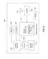
- FIG. 4illustrates an example positioning system 400 that switches power modes for auxiliary sensors according to an embodiment of the disclosure.
- Positioning system 400includes receiver 108 coupled to antenna 110 , position Kalman filter 112 , signal quality monitor 114 , auxiliary controller 402 , processor 404 , memory 406 , drivers 408 and auxiliary sensors 116 .
- Drivers 408may be hardware and/or software programs that allow auxiliary controller 402 to control auxiliary sensors 116 .
- Memory 406may store maps and/or program code.
- Processor 404may perform the steps described herein as performed by auxiliary controller 402 based on instructions stored in memory 406 .
- auxiliary controller 402generates a first signal that causes drivers 408 to activate auxiliary sensors 116 and calibrate them prior to entering a poor signal environment 300 .
- auxiliary controller 402may determine that the speed of vehicle 100 is decreasing below a pre-determined threshold based on data from positioning signals 106 . The decrease in speed may be an indication that vehicle 100 is on an off-ramp and is entering a poor signal environment 300 , for example, a city.
- auxiliary controller 402may determine that vehicle 100 is entering a poor signal environment 300 based on a current position and heading of vehicle 100 and a map stored in memory 406 that identifies poor signal environments.
- the auxiliary controllerknowing a current open road position, may detect that the vehicle 100 is approaching an urban environment based on the current position, speed variation, and by consulting a stored map of the area, and therefore determine that the auxiliary sensors 116 should be powered-up via drivers 408 , and calibrated for imminent future use.
- Auxiliary controller 402may also generate a signal to power down the auxiliary sensors 116 if the vehicle 100 is proximate to exiting a poor signal environment 300 . If a speed of the vehicle increases above a pre-determined threshold, it may indicate that the vehicle 100 is on an on-ramp and about to exit a poor signal environment 300 , such as city. Based on the speed of the vehicle 100 , the auxiliary control 402 may generate a signal that causes drivers 408 to power down auxiliary sensors 116 and thereby conserve battery 120 . In another example, auxiliary controller 402 may determine that a vehicle 100 is exiting a poor signal environment 300 based on a map stored in memory 406 .
- auxiliary sensor 116based on a current position and heading of a vehicle may determine that the vehicle is on an on-ramp and is exiting a poor signal environment, such as a city.
- the auxiliary controller 402may determine whether the vehicle 100 is entering or exiting a poor signal environment 300 based on one or more of a speed, position, heading of vehicle 100 , and the orientation of vehicle 100 with respect to its environment.
- FIG. 5illustrates an example process 500 illustrating steps performed by a positioning system to provide accurate positioning of a vehicle while conserving power according to an embodiment of the disclosure.
- Process 500will be described with continued reference to the example operating environment depicted in FIGS. 1-4 . However, the process is not limited to these embodiments. Note that some steps shown in process 500 do not necessarily have to occur in the order shown. In an example, the steps may be performed by auxiliary controller 402 . In another example, the steps described herein may be performed by processor 404 based on instructions stored in memory 406 .
- step 502it is determined whether a vehicle is entering or exiting a poor signal environment. For example, auxiliary controller 402 determines whether vehicle 100 is entering a poor signal environment based on one or more of a position of the vehicle, a speed of the vehicle, a speed variation of the vehicle, and a heading of vehicle 100 with respect to its environment. If it is determined, that the vehicle is entering a poor signal environment, then the process proceeds to step 504 .
- a signalis generated to power down an auxiliary device.
- auxiliary controller 402generates a signal that causes drivers 408 to power down auxiliary sensors 116 .
- step 506if it is determined that the vehicle is entering a poor signal environment, then auxiliary controller 402 generates signals that cause drivers 408 to power up auxiliary sensors 116 .
- auxiliary sensorsare calibrated prior to entering the poor signal environment.
- the accelerometer and/or gyroare calibrated to provide an accurate heading and position prior to entering a poor signal environment 300 .
- the auxiliary sensorsare utilized for position determination based on a starting location, and positional changes detected by the auxiliary sensors.
- the satellite-based positioning systemcan provide a starting location while still in a good signal environment, and just before entering the poor signal environment.
- the auxiliary sensorscan provide assistance data (speed, heading, orientation, etc.) associated with relative positional changes, as described herein, to accurately determine current position, relative to the starting location.
- the disclosurehas been described in the context of a moving vehicle, and can include any mode of transportation including, but not limited to: automobiles, trucks, trains, planes, boats, bicycles, even foot traffic, etc.
- the user devicecan be moving in an unspecified manner and perform the functions and features of the embodiments described herein.
- Embodiments presented herein, or portions thereof,can be implemented in hardware, firmware, software, and/or combinations thereof.
- the embodiments presented hereinapply to any communication system between two or more devices or within subcomponents of one device.
- the representative functions described hereincan be implemented in hardware, software, or some combination thereof.
- the representative functionscan be implemented using computer processors, computer logic, application specific circuits (ASIC), digital signal processors, etc., as will be understood by those skilled in the arts based on the discussion given herein. Accordingly, any processor that performs the functions described herein is within the scope and spirit of the embodiments presented herein.
- the followingdescribes a general purpose computer system that can be used to implement embodiments of the disclosure presented herein.
- the present disclosurecan be implemented in hardware, or as a combination of soft ware and hardware. Consequently, the disclosure may be implemented in the environment of a computer system or other processing system.
- An example of such a computer system 600is shown in FIG. 6 .
- one or more of the auxiliary controller 402 , processor 404 , Kalman Filter 112 , and their corresponding algorithms described hereincan be implemented utilizing all or parts of computer system 600 .
- the computer system 600includes one or more processors, such as processor 604 .
- Processor 604can be a special purpose or a general purpose digital signal processor.
- the processor 604is connected to a communication infrastructure 606 (for example, a bus or network).
- a communication infrastructure 606for example, a bus or network.
- Computer system 600also includes a main memory 605 , preferably random access memory (RAM), and may also include a secondary memory 610 .
- the secondary memory 610may include, for example, a hard disk drive 612 , and/or a RAID array 616 , and/or a removable storage drive 614 , representing a floppy disk drive, a magnetic tape drive, an optical disk drive, etc.
- the removable storage drive 614reads from and/or writes to a removable storage unit 618 in a well-known manner.
- Removable storage unit 618represents a floppy disk, magnetic tape, optical disk, etc.
- the removable storage unit 618includes a computer usable storage medium having stored therein computer software and/or data.
- secondary memory 610may include other similar means for allowing computer programs or other instructions to be loaded into computer system 600 .
- Such meansmay include, for example, a removable storage unit 622 and an interface 620 .
- Examples of such meansmay include a program cartridge and cartridge interface (such as that found in video game devices), a removable memory chip (such as an EPROM, or PROM) and associated socket, and other removable storage units 622 and interfaces 620 which allow software and data to be transferred from the removable storage unit 622 to computer system 600 .
- Computer system 600may also include a communications interface 624 .
- Communications interface 624allows software and data to be transferred between computer system 600 and external devices. Examples of communications interface 624 may include a modem, a network interface (such as an Ethernet card), a communications port, a PCMCIA slot and card, etc.
- Software and data transferred via communications interface 624are in the form of signals 628 which may be electronic, electromagnetic, optical or other signals capable of being received by communications interface 624 . These signals 628 are provided to communications interface 624 via a communications path 626 .
- Communications path 626carries signals 628 and may be implemented using wire or cable, fiber optics, a phone line, a cellular phone link, an RF link and other communications channels.
- computer program mediumand “computer usable medium” are used herein to generally refer to media such as removable storage drive 614 , a hard disk installed in hard disk drive 612 , and signals 628 . These computer program products are means for providing software to computer system 600 .
- Computer programsare stored in main memory 605 and/or secondary memory 610 . Computer programs may also be received via communications interface 624 . Such computer programs, when executed, enable the computer system 600 to implement the present disclosure as discussed herein. In particular, the computer programs, when executed, enable the processor 604 to implement the processes of the present disclosure. For example, when executed, the computer programs enable processor 604 to implement part of or all of the steps described above with reference to the flowcharts herein. Where the disclosure is implemented using software, the software may be stored in a computer program product and loaded into computer system 600 using raid array 616 , removable storage drive 614 , hard drive 612 or communications interface 624 .
- features of the disclosureare implemented primarily in hardware using, for example, hardware components such as Application Specific Integrated Circuits (ASICs) and programmable or static gate arrays.
- ASICsApplication Specific Integrated Circuits
- programmable or static gate arraysprogrammable or static gate arrays
Landscapes
- Engineering & Computer Science (AREA)
- Radar, Positioning & Navigation (AREA)
- Remote Sensing (AREA)
- Computer Networks & Wireless Communication (AREA)
- Physics & Mathematics (AREA)
- General Physics & Mathematics (AREA)
- Navigation (AREA)
- Position Fixing By Use Of Radio Waves (AREA)
Abstract
Description
Claims (21)
Priority Applications (5)
| Application Number | Priority Date | Filing Date | Title |
|---|---|---|---|
| US13/545,717US9116233B2 (en) | 2012-07-10 | 2012-07-10 | Power mode control for sensors |
| EP20130003379EP2685282A1 (en) | 2012-07-10 | 2013-07-03 | Power mode control for sensors |
| TW102124355ATW201418749A (en) | 2012-07-10 | 2013-07-08 | Power mode control for sensors |
| CN201310289101.0ACN103543458B (en) | 2012-07-10 | 2013-07-10 | For the power mode control of sensor |
| KR1020130081044AKR101476415B1 (en) | 2012-07-10 | 2013-07-10 | Power mode control for sensors |
Applications Claiming Priority (1)
| Application Number | Priority Date | Filing Date | Title |
|---|---|---|---|
| US13/545,717US9116233B2 (en) | 2012-07-10 | 2012-07-10 | Power mode control for sensors |
Publications (2)
| Publication Number | Publication Date |
|---|---|
| US20140019044A1 US20140019044A1 (en) | 2014-01-16 |
| US9116233B2true US9116233B2 (en) | 2015-08-25 |
Family
ID=48746200
Family Applications (1)
| Application Number | Title | Priority Date | Filing Date |
|---|---|---|---|
| US13/545,717Active2032-11-17US9116233B2 (en) | 2012-07-10 | 2012-07-10 | Power mode control for sensors |
Country Status (5)
| Country | Link |
|---|---|
| US (1) | US9116233B2 (en) |
| EP (1) | EP2685282A1 (en) |
| KR (1) | KR101476415B1 (en) |
| CN (1) | CN103543458B (en) |
| TW (1) | TW201418749A (en) |
Cited By (1)
| Publication number | Priority date | Publication date | Assignee | Title |
|---|---|---|---|---|
| US10573273B2 (en) | 2018-06-13 | 2020-02-25 | Mapsted Corp. | Method and system for device placement based optimization techniques |
Families Citing this family (14)
| Publication number | Priority date | Publication date | Assignee | Title |
|---|---|---|---|---|
| CN103926602B (en)* | 2014-03-20 | 2017-02-08 | 联想(北京)有限公司 | Information processing method and electronic equipment |
| JP6082415B2 (en)* | 2015-03-03 | 2017-02-15 | 富士重工業株式会社 | Vehicle travel control device |
| CN105203098B (en)* | 2015-10-13 | 2018-10-02 | 上海华测导航技术股份有限公司 | Agricultural machinery all-attitude angle update method based on nine axis MEMS sensors |
| KR102457768B1 (en) | 2015-11-20 | 2022-10-21 | 삼성전자주식회사 | Method and appartus for operating electronic device based on environmental information |
| CN105425260B (en)* | 2016-01-13 | 2018-01-12 | 福建三鑫隆信息技术开发股份有限公司 | A kind of medium and long distance intelligent read well lid equipment of high position precision and its recognition methods |
| US10527736B2 (en)* | 2016-03-17 | 2020-01-07 | Cm Hk Limited | Methods and mobile devices with electric vehicle transportation detection |
| US10126722B2 (en)* | 2016-08-01 | 2018-11-13 | Qualcomm Incorporated | System and method of dynamically controlling parameters for processing sensor output data for collision avoidance and path planning |
| US10202115B2 (en)* | 2016-09-13 | 2019-02-12 | Here Global B.V. | Method and apparatus for triggering vehicle sensors based on human accessory detection |
| WO2018102146A1 (en) | 2016-12-01 | 2018-06-07 | Google Llc | Methods and systems for location determination |
| US12140686B2 (en) | 2019-03-01 | 2024-11-12 | Google Llc | Determining velocity using a reflected positioning signal |
| US20200340816A1 (en)* | 2019-04-26 | 2020-10-29 | Mediatek Inc. | Hybrid positioning system with scene detection |
| EP3997485B1 (en) | 2019-07-08 | 2025-09-03 | Google LLC | Enhancing sensitivity to reflected gnss signals |
| CN113720336B (en)* | 2021-08-10 | 2022-11-22 | 广东汇天航空航天科技有限公司 | Course information determining method, vehicle and computer readable storage medium |
| US11822466B2 (en) | 2021-12-21 | 2023-11-21 | Dspace Gmbh | Creating and testing a control-device program |
Citations (48)
| Publication number | Priority date | Publication date | Assignee | Title |
|---|---|---|---|---|
| US5416712A (en)* | 1993-05-28 | 1995-05-16 | Trimble Navigation Limited | Position and velocity estimation system for adaptive weighting of GPS and dead-reckoning information |
| US5657025A (en)* | 1995-08-07 | 1997-08-12 | Litton Systems, Inc. | Integrated GPS/inertial navigation apparatus providing improved heading estimates |
| US6321158B1 (en)* | 1994-06-24 | 2001-11-20 | Delorme Publishing Company | Integrated routing/mapping information |
| US20020014990A1 (en)* | 2000-06-12 | 2002-02-07 | Masayuki Kimura | Radio communication device and method of measuring distance |
| US20020177476A1 (en)* | 2001-05-22 | 2002-11-28 | Chou Y. Hong | Durable global asset-tracking device and a method of using the same |
| US20030195008A1 (en)* | 2000-07-14 | 2003-10-16 | Norman Mohi | Locating system and method |
| US20040002814A1 (en)* | 2002-06-27 | 2004-01-01 | Gogic Aleksander M. | Controlling geographic location information of devices operating in wireless communication systems |
| US20070239813A1 (en) | 2006-04-11 | 2007-10-11 | Motorola, Inc. | Method and system of utilizing a context vector and method and system of utilizing a context vector and database for location applications |
| US20070236387A1 (en)* | 2005-12-29 | 2007-10-11 | Alcatel Lucent | Method of optimization of processing of location data in the presence of a plurality of satellite positioning constellations |
| US20080129598A1 (en)* | 2005-01-11 | 2008-06-05 | Baptiste Godefroy | Positioning Method and Device |
| US7386389B2 (en)* | 2003-11-20 | 2008-06-10 | Beyerische Motoren Werke Aktiengesellschaft | Method and system for determining the driving situation |
| TW200837330A (en) | 2007-03-09 | 2008-09-16 | Mitac Int Corp | Integrated positioning apparatus and implementation method thereof |
| US20090098880A1 (en) | 2007-10-16 | 2009-04-16 | Sony Ericsson Mobile Communications Ab | Mobile terminals and methods for regulating power-on/off of a gps positioning circuit |
| US20090138200A1 (en)* | 2007-07-05 | 2009-05-28 | Andrew Hunter | Portable Navigation System |
| US20100039316A1 (en)* | 2008-02-25 | 2010-02-18 | Sirf Technology, Inc. | System and Method for Operating a GPS Device in a Micro Power Mode |
| US7679554B1 (en)* | 2006-03-06 | 2010-03-16 | Rockwell Collins, Inc. | Communications link time transfer to improve navigation system accuracy |
| US20100106397A1 (en)* | 2007-04-06 | 2010-04-29 | Rob Van Essen | Method, navigation device, and server for determining a location in a digital map database |
| US20100109865A1 (en)* | 2007-06-20 | 2010-05-06 | Armstrong Keith C | System and method for locating an individual |
| US20100125413A1 (en) | 2008-11-17 | 2010-05-20 | Benjamin Wang | External gyroscope and method of using the same to assist in navigation and positioning |
| US20100149030A1 (en)* | 2002-08-15 | 2010-06-17 | Rajiv Kumar Verma | Position determination system and method |
| US20100164789A1 (en)* | 2008-12-30 | 2010-07-01 | Gm Global Technology Operations, Inc. | Measurement Level Integration of GPS and Other Range and Bearing Measurement-Capable Sensors for Ubiquitous Positioning Capability |
| US20100178934A1 (en)* | 2009-01-13 | 2010-07-15 | Qualcomm Incorporated | Environment-specific measurement weighting in wireless positioning |
| US20100211307A1 (en)* | 2006-01-18 | 2010-08-19 | Pieter Geelen | Method of Storing the Position of a Parked Vehicle and Navigation Device Arranged for That |
| CN101858980A (en) | 2010-05-18 | 2010-10-13 | 东南大学 | A vehicle-mounted intelligent ultra-tight integrated navigation method based on GPS software receiver |
| US20100280751A1 (en)* | 1997-10-22 | 2010-11-04 | Intelligent Technologies International, Inc. | Road physical condition monitoring techniques |
| US20110071759A1 (en)* | 2009-09-22 | 2011-03-24 | Texas Instruments Incorporated | Performance of a Navigation Receiver Operating in a Power-Save Mode with the Aid of Sensors |
| US20110140956A1 (en)* | 2009-12-15 | 2011-06-16 | Paul Henry | Systems and Methods for Determining Geographic Location of a Mobile Device |
| US20110187596A1 (en)* | 2010-02-03 | 2011-08-04 | Texas Instruments Incorporated | Receivers, circuits, and methods to improve gnss time-to-fix and other performances |
| CN102169182A (en) | 2010-02-26 | 2011-08-31 | 宏达国际电子股份有限公司 | Mobile navigation device |
| CN201985995U (en) | 2010-12-29 | 2011-09-21 | 上海华勤通讯技术有限公司 | Mobile terminal capable of being positioned under weak positioning signal |
| EP2372306A2 (en) | 2010-03-31 | 2011-10-05 | Alpine Electronics, Inc. | Method and apparatus for efficiently using a battery in a smartphone having a navigation system |
| US20110250931A1 (en)* | 2010-04-08 | 2011-10-13 | Tarkesh Pande | Static Heading Detection in Personal Navigation Device |
| US20120109517A1 (en) | 2010-10-27 | 2012-05-03 | Denso Corporation | Mobile object positioning device and navigation apparatus |
| US20120112958A1 (en) | 2010-11-03 | 2012-05-10 | Farshid Alizadeh-Shabdiz | Method of and system for increasing the reliability and accuracy of location estimation in a hybrid positioning system |
| US20120116677A1 (en)* | 2008-11-04 | 2012-05-10 | The University Court Of The University Of Edinburgh | Assisted positioning systems |
| EP2453262A2 (en) | 2010-11-11 | 2012-05-16 | Sony Corporation | Position information detection device, communication apparatus, and communication system |
| US20120133555A1 (en) | 2010-11-30 | 2012-05-31 | Samsung Electronics Co., Ltd. | Method and system for building location information database of access points and method for providing location information using the same |
| KR20120056687A (en) | 2010-11-25 | 2012-06-04 | 삼성전자주식회사 | Method for providing location information and apparatus for the same |
| US20120139775A1 (en)* | 2010-12-02 | 2012-06-07 | Honda Motor Co., Ltd. | Method for Testing GNSS-Based Positioning Systems in Obstructed Environments |
| CN202305805U (en) | 2011-09-30 | 2012-07-04 | 深圳市元征软件开发有限公司 | Vehicle GPS tracking positioning system having no blind area |
| US20120176491A1 (en)* | 2011-01-11 | 2012-07-12 | Qualcomm Incorporated | Camera-based position location and navigation based on image processing |
| US20120220308A1 (en)* | 2011-02-25 | 2012-08-30 | Nokia Corporation | Method and apparatus for pre-fetching location-based data while maintaining user privacy |
| US20120303254A1 (en)* | 2011-05-27 | 2012-11-29 | Honda Motor Co., Ltd. | System and method for comparing vehicle economy based on driving levels |
| US20120309415A1 (en)* | 2010-07-21 | 2012-12-06 | Zulutime, Llc | Multipath compensation within geolocation of mobile devices |
| US20130002857A1 (en)* | 2011-06-30 | 2013-01-03 | Qualcomm Incorporated | Navigation in buildings with rectangular floor plan |
| US20130069821A1 (en)* | 2011-09-21 | 2013-03-21 | Cambridge Silicon Radio Ltd. | Method and Apparatus of Using Height Aiding From a Contour Table for GNSS Positioning |
| US20130158857A1 (en)* | 2011-12-19 | 2013-06-20 | Texas Instruments Incorporated | Power and performance optimization in navigation systems |
| US8694251B2 (en)* | 2010-11-25 | 2014-04-08 | Texas Instruments Incorporated | Attitude estimation for pedestrian navigation using low cost mems accelerometer in mobile applications, and processing methods, apparatus and systems |
Family Cites Families (4)
| Publication number | Priority date | Publication date | Assignee | Title |
|---|---|---|---|---|
| US6922632B2 (en)* | 2002-08-09 | 2005-07-26 | Intersense, Inc. | Tracking, auto-calibration, and map-building system |
| JP4229141B2 (en)* | 2006-06-19 | 2009-02-25 | トヨタ自動車株式会社 | Vehicle state quantity estimation device and vehicle steering control device using the device |
| JP2010091454A (en)* | 2008-10-09 | 2010-04-22 | Panasonic Corp | Apparatus for measuring vehicle travel speed |
| KR101114883B1 (en)* | 2010-02-16 | 2012-02-27 | 이강원 | A portable navigation terminal for bicycle having power saving and wireless communication functions, the control method thereof, and the bicycle anti-theft system using the same |
- 2012
- 2012-07-10USUS13/545,717patent/US9116233B2/enactiveActive
- 2013
- 2013-07-03EPEP20130003379patent/EP2685282A1/ennot_activeWithdrawn
- 2013-07-08TWTW102124355Apatent/TW201418749A/enunknown
- 2013-07-10KRKR1020130081044Apatent/KR101476415B1/enactiveActive
- 2013-07-10CNCN201310289101.0Apatent/CN103543458B/ennot_activeExpired - Fee Related
Patent Citations (53)
| Publication number | Priority date | Publication date | Assignee | Title |
|---|---|---|---|---|
| US5416712A (en)* | 1993-05-28 | 1995-05-16 | Trimble Navigation Limited | Position and velocity estimation system for adaptive weighting of GPS and dead-reckoning information |
| US6321158B1 (en)* | 1994-06-24 | 2001-11-20 | Delorme Publishing Company | Integrated routing/mapping information |
| US5657025A (en)* | 1995-08-07 | 1997-08-12 | Litton Systems, Inc. | Integrated GPS/inertial navigation apparatus providing improved heading estimates |
| US20100280751A1 (en)* | 1997-10-22 | 2010-11-04 | Intelligent Technologies International, Inc. | Road physical condition monitoring techniques |
| US20020014990A1 (en)* | 2000-06-12 | 2002-02-07 | Masayuki Kimura | Radio communication device and method of measuring distance |
| US20030195008A1 (en)* | 2000-07-14 | 2003-10-16 | Norman Mohi | Locating system and method |
| US20020177476A1 (en)* | 2001-05-22 | 2002-11-28 | Chou Y. Hong | Durable global asset-tracking device and a method of using the same |
| US20040002814A1 (en)* | 2002-06-27 | 2004-01-01 | Gogic Aleksander M. | Controlling geographic location information of devices operating in wireless communication systems |
| US20100149030A1 (en)* | 2002-08-15 | 2010-06-17 | Rajiv Kumar Verma | Position determination system and method |
| US7386389B2 (en)* | 2003-11-20 | 2008-06-10 | Beyerische Motoren Werke Aktiengesellschaft | Method and system for determining the driving situation |
| US20080129598A1 (en)* | 2005-01-11 | 2008-06-05 | Baptiste Godefroy | Positioning Method and Device |
| US20070236387A1 (en)* | 2005-12-29 | 2007-10-11 | Alcatel Lucent | Method of optimization of processing of location data in the presence of a plurality of satellite positioning constellations |
| US20100211307A1 (en)* | 2006-01-18 | 2010-08-19 | Pieter Geelen | Method of Storing the Position of a Parked Vehicle and Navigation Device Arranged for That |
| US7679554B1 (en)* | 2006-03-06 | 2010-03-16 | Rockwell Collins, Inc. | Communications link time transfer to improve navigation system accuracy |
| US20070239813A1 (en) | 2006-04-11 | 2007-10-11 | Motorola, Inc. | Method and system of utilizing a context vector and method and system of utilizing a context vector and database for location applications |
| US20090076727A1 (en) | 2007-03-09 | 2009-03-19 | Lien Te Ti | Integrated positioning apparatus and implementation method thereof |
| TW200837330A (en) | 2007-03-09 | 2008-09-16 | Mitac Int Corp | Integrated positioning apparatus and implementation method thereof |
| US20100106397A1 (en)* | 2007-04-06 | 2010-04-29 | Rob Van Essen | Method, navigation device, and server for determining a location in a digital map database |
| US20100109865A1 (en)* | 2007-06-20 | 2010-05-06 | Armstrong Keith C | System and method for locating an individual |
| US20090138200A1 (en)* | 2007-07-05 | 2009-05-28 | Andrew Hunter | Portable Navigation System |
| US20090098880A1 (en) | 2007-10-16 | 2009-04-16 | Sony Ericsson Mobile Communications Ab | Mobile terminals and methods for regulating power-on/off of a gps positioning circuit |
| US20100039316A1 (en)* | 2008-02-25 | 2010-02-18 | Sirf Technology, Inc. | System and Method for Operating a GPS Device in a Micro Power Mode |
| US20120116677A1 (en)* | 2008-11-04 | 2012-05-10 | The University Court Of The University Of Edinburgh | Assisted positioning systems |
| US20100125413A1 (en) | 2008-11-17 | 2010-05-20 | Benjamin Wang | External gyroscope and method of using the same to assist in navigation and positioning |
| US20100164789A1 (en)* | 2008-12-30 | 2010-07-01 | Gm Global Technology Operations, Inc. | Measurement Level Integration of GPS and Other Range and Bearing Measurement-Capable Sensors for Ubiquitous Positioning Capability |
| US20100178934A1 (en)* | 2009-01-13 | 2010-07-15 | Qualcomm Incorporated | Environment-specific measurement weighting in wireless positioning |
| US20110071759A1 (en)* | 2009-09-22 | 2011-03-24 | Texas Instruments Incorporated | Performance of a Navigation Receiver Operating in a Power-Save Mode with the Aid of Sensors |
| US20110140956A1 (en)* | 2009-12-15 | 2011-06-16 | Paul Henry | Systems and Methods for Determining Geographic Location of a Mobile Device |
| US20110187596A1 (en)* | 2010-02-03 | 2011-08-04 | Texas Instruments Incorporated | Receivers, circuits, and methods to improve gnss time-to-fix and other performances |
| CN102169182A (en) | 2010-02-26 | 2011-08-31 | 宏达国际电子股份有限公司 | Mobile navigation device |
| US8332140B2 (en) | 2010-03-31 | 2012-12-11 | Alpine Electronics, Inc | Method and apparatus for efficiently using a battery in a smartphone having a navigation system |
| EP2372306A2 (en) | 2010-03-31 | 2011-10-05 | Alpine Electronics, Inc. | Method and apparatus for efficiently using a battery in a smartphone having a navigation system |
| CN102209153A (en) | 2010-03-31 | 2011-10-05 | 阿尔派株式会社 | Method and apparatus for efficiently using battery in smartphone having navigation system |
| US20110250931A1 (en)* | 2010-04-08 | 2011-10-13 | Tarkesh Pande | Static Heading Detection in Personal Navigation Device |
| CN101858980A (en) | 2010-05-18 | 2010-10-13 | 东南大学 | A vehicle-mounted intelligent ultra-tight integrated navigation method based on GPS software receiver |
| US20120309415A1 (en)* | 2010-07-21 | 2012-12-06 | Zulutime, Llc | Multipath compensation within geolocation of mobile devices |
| US20120109517A1 (en) | 2010-10-27 | 2012-05-03 | Denso Corporation | Mobile object positioning device and navigation apparatus |
| US20120112958A1 (en) | 2010-11-03 | 2012-05-10 | Farshid Alizadeh-Shabdiz | Method of and system for increasing the reliability and accuracy of location estimation in a hybrid positioning system |
| EP2453262A2 (en) | 2010-11-11 | 2012-05-16 | Sony Corporation | Position information detection device, communication apparatus, and communication system |
| KR20120056687A (en) | 2010-11-25 | 2012-06-04 | 삼성전자주식회사 | Method for providing location information and apparatus for the same |
| US8694251B2 (en)* | 2010-11-25 | 2014-04-08 | Texas Instruments Incorporated | Attitude estimation for pedestrian navigation using low cost mems accelerometer in mobile applications, and processing methods, apparatus and systems |
| US20130237248A1 (en) | 2010-11-25 | 2013-09-12 | Kyong-Ha Park | Apparatus and method for providing location information |
| US20120133555A1 (en) | 2010-11-30 | 2012-05-31 | Samsung Electronics Co., Ltd. | Method and system for building location information database of access points and method for providing location information using the same |
| KR20120058946A (en) | 2010-11-30 | 2012-06-08 | 삼성전자주식회사 | Method and system for building a location information database of access point and method for providing a location information using the same |
| US20120139775A1 (en)* | 2010-12-02 | 2012-06-07 | Honda Motor Co., Ltd. | Method for Testing GNSS-Based Positioning Systems in Obstructed Environments |
| CN201985995U (en) | 2010-12-29 | 2011-09-21 | 上海华勤通讯技术有限公司 | Mobile terminal capable of being positioned under weak positioning signal |
| US20120176491A1 (en)* | 2011-01-11 | 2012-07-12 | Qualcomm Incorporated | Camera-based position location and navigation based on image processing |
| US20120220308A1 (en)* | 2011-02-25 | 2012-08-30 | Nokia Corporation | Method and apparatus for pre-fetching location-based data while maintaining user privacy |
| US20120303254A1 (en)* | 2011-05-27 | 2012-11-29 | Honda Motor Co., Ltd. | System and method for comparing vehicle economy based on driving levels |
| US20130002857A1 (en)* | 2011-06-30 | 2013-01-03 | Qualcomm Incorporated | Navigation in buildings with rectangular floor plan |
| US20130069821A1 (en)* | 2011-09-21 | 2013-03-21 | Cambridge Silicon Radio Ltd. | Method and Apparatus of Using Height Aiding From a Contour Table for GNSS Positioning |
| CN202305805U (en) | 2011-09-30 | 2012-07-04 | 深圳市元征软件开发有限公司 | Vehicle GPS tracking positioning system having no blind area |
| US20130158857A1 (en)* | 2011-12-19 | 2013-06-20 | Texas Instruments Incorporated | Power and performance optimization in navigation systems |
Non-Patent Citations (10)
| Title |
|---|
| English language abstract for Chinese Patent Publication No. 102169182 A, published Aug. 31, 2011, 1 page. |
| English language abstract for Chinese Patent Publication No. 102209153 A, published Oct. 5, 2011, 2 pages. |
| English language abstract for Chinese Patent Publication No. CN 101858980 A, published Oct. 13, 2010, 1 page. |
| English language abstract for Chinese Patent Publication No. CN 201985995 U, published Sep. 21, 2011, 1 page. |
| English language abstract for Chinese Patent Publication No. CN 202305805 U, published Jul. 4, 2012, 1 page. |
| English language abstract for Taiwanese Patent Publication No. 200837330 A, published Sep. 16, 2008, 1 page. |
| European Search Report directed to related European Patent Application No. 13 00 3379, Munich, Germany, mailed Nov. 15, 2013, 3 pages. |
| Office Action directed to related Korean Patent Application No. 10-2013-0081044, mailed Jun. 16, 2014; 4 pages. |
| Office Action, dated Jan. 20, 2015, for Chinese Patent Application No. 2013102891010, 6 pages. |
| Virginia Driver's Manual, 2014, all pages, http://www.dmv.state.va.us/webdoc/pdf/dmv39.pdf.* |
Cited By (1)
| Publication number | Priority date | Publication date | Assignee | Title |
|---|---|---|---|---|
| US10573273B2 (en) | 2018-06-13 | 2020-02-25 | Mapsted Corp. | Method and system for device placement based optimization techniques |
Also Published As
| Publication number | Publication date |
|---|---|
| KR101476415B1 (en) | 2014-12-24 |
| TW201418749A (en) | 2014-05-16 |
| CN103543458B (en) | 2016-01-06 |
| CN103543458A (en) | 2014-01-29 |
| KR20140007776A (en) | 2014-01-20 |
| EP2685282A1 (en) | 2014-01-15 |
| US20140019044A1 (en) | 2014-01-16 |
Similar Documents
| Publication | Publication Date | Title |
|---|---|---|
| US9116233B2 (en) | Power mode control for sensors | |
| US8009087B2 (en) | Positioning system and method thereof | |
| US10955556B2 (en) | Fast GPS recovery using map vector data | |
| KR101353755B1 (en) | Satellite positioning system receivers and methods | |
| EP2929294B1 (en) | Determination of position, velocity and/or heading by simultaneous use of on-device and on-vehicle information | |
| US8630798B2 (en) | Electronic system and method for personal navigation | |
| US11917497B2 (en) | Variable ping rate for a location tracker | |
| US20090267832A1 (en) | Systems and methods for dynamically determining position | |
| US20220179104A1 (en) | Position estimation device and position estimation method | |
| KR20140104484A (en) | Location and event triggered navigation dormancy and wakeup | |
| US20160088422A1 (en) | Systems and methods for sharing location data within a vehicle | |
| US20120176270A1 (en) | Method for providing reliability of reckoning location and mobile terminal therefor | |
| KR20190010267A (en) | Navigation apparatus and method for vehicle, and navigation system | |
| US20090149201A1 (en) | Apparatus and method for providing position information of wireless terminal | |
| US20110301834A1 (en) | Device and method for vehicle navigation | |
| US20130158857A1 (en) | Power and performance optimization in navigation systems | |
| JP2014142185A (en) | On-board device, terminal unit and navigation system | |
| KR101501839B1 (en) | System for estimating position | |
| HK1191404A (en) | Power mode control for sensors | |
| KR20240165143A (en) | Apparatus for outputting pseudo GNSS signal and controlling the same |
Legal Events
| Date | Code | Title | Description |
|---|---|---|---|
| AS | Assignment | Owner name:BROADCOM CORPORATION, CALIFORNIA Free format text:ASSIGNMENT OF ASSIGNORS INTEREST;ASSIGNORS:ZANUTTA, ROBERTO ERNESTO;VAN DIGGELEN, FRANK;MALKOS, STEVEN;REEL/FRAME:028524/0047 Effective date:20120705 | |
| STCF | Information on status: patent grant | Free format text:PATENTED CASE | |
| AS | Assignment | Owner name:BANK OF AMERICA, N.A., AS COLLATERAL AGENT, NORTH CAROLINA Free format text:PATENT SECURITY AGREEMENT;ASSIGNOR:BROADCOM CORPORATION;REEL/FRAME:037806/0001 Effective date:20160201 Owner name:BANK OF AMERICA, N.A., AS COLLATERAL AGENT, NORTH Free format text:PATENT SECURITY AGREEMENT;ASSIGNOR:BROADCOM CORPORATION;REEL/FRAME:037806/0001 Effective date:20160201 | |
| AS | Assignment | Owner name:AVAGO TECHNOLOGIES GENERAL IP (SINGAPORE) PTE. LTD., SINGAPORE Free format text:ASSIGNMENT OF ASSIGNORS INTEREST;ASSIGNOR:BROADCOM CORPORATION;REEL/FRAME:041706/0001 Effective date:20170120 Owner name:AVAGO TECHNOLOGIES GENERAL IP (SINGAPORE) PTE. LTD Free format text:ASSIGNMENT OF ASSIGNORS INTEREST;ASSIGNOR:BROADCOM CORPORATION;REEL/FRAME:041706/0001 Effective date:20170120 | |
| AS | Assignment | Owner name:BROADCOM CORPORATION, CALIFORNIA Free format text:TERMINATION AND RELEASE OF SECURITY INTEREST IN PATENTS;ASSIGNOR:BANK OF AMERICA, N.A., AS COLLATERAL AGENT;REEL/FRAME:041712/0001 Effective date:20170119 | |
| AS | Assignment | Owner name:AVAGO TECHNOLOGIES INTERNATIONAL SALES PTE. LIMITE Free format text:MERGER;ASSIGNOR:AVAGO TECHNOLOGIES GENERAL IP (SINGAPORE) PTE. LTD.;REEL/FRAME:047229/0408 Effective date:20180509 | |
| AS | Assignment | Owner name:AVAGO TECHNOLOGIES INTERNATIONAL SALES PTE. LIMITE Free format text:CORRECTIVE ASSIGNMENT TO CORRECT THE EFFECTIVE DATE PREVIOUSLY RECORDED ON REEL 047229 FRAME 0408. ASSIGNOR(S) HEREBY CONFIRMS THE THE EFFECTIVE DATE IS 09/05/2018;ASSIGNOR:AVAGO TECHNOLOGIES GENERAL IP (SINGAPORE) PTE. LTD.;REEL/FRAME:047349/0001 Effective date:20180905 | |
| MAFP | Maintenance fee payment | Free format text:PAYMENT OF MAINTENANCE FEE, 4TH YEAR, LARGE ENTITY (ORIGINAL EVENT CODE: M1551); ENTITY STATUS OF PATENT OWNER: LARGE ENTITY Year of fee payment:4 | |
| AS | Assignment | Owner name:AVAGO TECHNOLOGIES INTERNATIONAL SALES PTE. LIMITE Free format text:CORRECTIVE ASSIGNMENT TO CORRECT THE PATENT NUMBER 9,385,856 TO 9,385,756 PREVIOUSLY RECORDED AT REEL: 47349 FRAME: 001. ASSIGNOR(S) HEREBY CONFIRMS THE MERGER;ASSIGNOR:AVAGO TECHNOLOGIES GENERAL IP (SINGAPORE) PTE. LTD.;REEL/FRAME:051144/0648 Effective date:20180905 | |
| MAFP | Maintenance fee payment | Free format text:PAYMENT OF MAINTENANCE FEE, 8TH YEAR, LARGE ENTITY (ORIGINAL EVENT CODE: M1552); ENTITY STATUS OF PATENT OWNER: LARGE ENTITY Year of fee payment:8 |