US9115475B2 - Ski slope snow grooming method and relative implement - Google Patents
Ski slope snow grooming method and relative implementDownload PDFInfo
- Publication number
- US9115475B2 US9115475B2US13/812,109US201113812109AUS9115475B2US 9115475 B2US9115475 B2US 9115475B2US 201113812109 AUS201113812109 AUS 201113812109AUS 9115475 B2US9115475 B2US 9115475B2
- Authority
- US
- United States
- Prior art keywords
- snow
- snow covering
- ski slope
- coherent
- covering
- Prior art date
- Legal status (The legal status is an assumption and is not a legal conclusion. Google has not performed a legal analysis and makes no representation as to the accuracy of the status listed.)
- Expired - Fee Related, expires
Links
- 230000003370grooming effectEffects0.000titleclaimsabstractdescription30
- 238000000034methodMethods0.000titleclaimsabstractdescription25
- 230000000712assemblyEffects0.000claims2
- 238000000429assemblyMethods0.000claims2
- 230000008901benefitEffects0.000description6
- 238000012986modificationMethods0.000description3
- 230000004048modificationEffects0.000description3
- 239000002245particleSubstances0.000description3
- 239000002344surface layerSubstances0.000description2
- 241000951897Mystrium mirrorSpecies0.000description1
- 238000007796conventional methodMethods0.000description1
- 230000003467diminishing effectEffects0.000description1
- XLYOFNOQVPJJNP-UHFFFAOYSA-NwaterSubstancesOXLYOFNOQVPJJNP-UHFFFAOYSA-N0.000description1
Images


Classifications
- E—FIXED CONSTRUCTIONS
- E01—CONSTRUCTION OF ROADS, RAILWAYS, OR BRIDGES
- E01H—STREET CLEANING; CLEANING OF PERMANENT WAYS; CLEANING BEACHES; DISPERSING OR PREVENTING FOG IN GENERAL CLEANING STREET OR RAILWAY FURNITURE OR TUNNEL WALLS
- E01H4/00—Working on surfaces of snow or ice in order to make them suitable for traffic or sporting purposes, e.g. by compacting snow
- E01H4/02—Working on surfaces of snow or ice in order to make them suitable for traffic or sporting purposes, e.g. by compacting snow for sporting purposes, e.g. preparation of ski trails; Construction of artificial surfacings for snow or ice sports ; Trails specially adapted for on-the-snow vehicles, e.g. devices adapted for ski-trails
Definitions
- Certain known methods of grooming the snow covering of ski slopesis to flatten any mounds of snow using a blade fitted to the front of a crawler groomer; compact the snow covering using the groomer tracks; till a surface layer of the snow covering using a rotary tiller fitted to the rear of the groomer; and smooth the tilled snow covering using a mat mounted downstream from the rotary tiller, and which forms longitudinal furrows parallel to the travelling direction of the groomer.
- the most energy-intensive grooming stepis tilling the snow covering, especially when this is hard and icy.
- the rotary tillercomprises a shaft rotated by a hydraulic or electric motor; and a number of teeth projecting from the shaft.
- the tilleris confined between the snow covering and a hood and, in use, the teeth on the tiller penetrate the snow covering and hurl clumps of snow against the hood to break up the clumps and form a hard surface layer on the snow covering of a given or designated particle size.
- the present disclosurerelates to a ski slope snow grooming method.
- a method of grooming the snow covering of ski slopescomprising the steps of moving a ski slope grooming implement in a travelling direction along the snow covering; and projecting coherent-energy beams from the implement onto the snow covering to form furrows in the snow covering.
- the coherent-energy beamsare defined by electromagnetic waves in the visible range. In one such embodiment, the coherent-energy beams are defined by laser beams.
- the methodcomprises selecting the power of each coherent-energy beam as a function of the travelling speed of the coherent-energy beam.
- the methodcomprises selecting the power of each coherent-energy beam as a function of the depth of the respective furrow.
- the methodcomprises selecting the tilt of the coherent-energy beam with respect to the surface of the snow covering.
- Another advantage of the present disclosureis to provide an implement configured or designed to eliminate certain of the above-described drawbacks of such known ski slope snow grooming implements.
- an implementconfigured to groom the snow covering of ski slopes, the implement being configured or designed to be moved in a travelling direction along the snow covering, and comprising a number or quantity of emitters configured to emit and project coherent-energy beams onto the snow covering to form furrows in the snow covering.
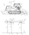
- FIG. 1shows a side view, with parts removed for clarity, of a groomer configured to implement the ski slope snow grooming method according to the present disclosure
- FIG. 2shows a schematic, with parts removed for clarity, of an implement configured to implement the grooming method according to the present disclosure
- FIGS. 3 and 4show sections of the snow covering groomed using the method according to the present disclosure.
- FIGS. 5 , 6 , 7 and 8show schematic plan views of respective portions of snow covering groomed using the method according to the present disclosure.
- number 1 in FIG. 1indicates as a whole a ski slope groomer.
- Groomer 1comprises a frame 2 ; tracks 3 looped about wheels 4 ; an engine compartment 5 ; and a cab 6 .
- the groomer 1 in FIG. 1also comprises a winch 7 configured to assist the groomer up particularly steep slopes.
- Groomer 1is configured or designed to groom a snow covering M, along which it is driven in a direction D at a variable travelling speed V, and accordingly comprises a blade 8 fitted to the front of frame 2 to flatten any mounds of snow; and a grooming device 9 fitted to the rear of frame 2 to groom snow covering M to a smooth, ski-safe conformation.
- grooming device 9comprises a succession of three implements 10 , 11 , 12 .
- Implements 11 and 12are conventional types defined by a tiller 13 housed in a hood 14 , and by a flexible mat 15 respectively.
- implement 10is configured or designed to groom snow covering M either in conjunction with implements 11 and 12 , or independently, in which case, it is capable of grooming snow covering M completely, with no help from implements 11 and 12 .
- implement 10is configured or designed to project coherent-energy beams 16 onto snow covering M, to form furrows 17 , 18 , 19 in snow covering M as it travels in direction D at speed V.
- Each coherent-energy beam 16interacts with snow covering M to melt a portion of snow covering M; furrows 17 , 18 , 19 are formed by the movement of coherent-energy beams 16 along snow covering M; and the movement of each coherent-energy beam 16 is produced by the movement of groomer 1 in travelling direction D (as seen in FIG. 1 ) and by any additional movements of coherent-energy beam 16 .
- coherent-energy beam 16is defined by a laser beam, but alternative embodiments of the present disclosure employ electromagnetic waves, microwaves, sound waves, water jets, and air jets in general.
- the depth of furrows 17 , 18 , 19depends on the energy discharged onto snow covering M, and on the characteristics of snow covering M, such as density, particle size and temperature; the instantaneous energy discharged onto snow covering M depends on the power of coherent-energy beam 16 and the travelling speed of coherent-energy beam 16 with respect to snow covering M; and the travelling speed of coherent-energy beam 16 depends on the travelling speed V of groomer 1 , and the speed of any additional movement of coherent-energy beam 16 .
- the power of coherent-energy beam 16is adjustable according to the characteristics of snow covering M, the target depth of furrow 17 , 18 or 19 , travelling speed V, and the speed of any additional movement of coherent-energy beam 16 , and can be adjusted both manually and automatically as a function of travelling speed V. In automatic adjustment mode, all other characteristics being equal, the power of coherent-energy beam 16 increases linearly with travelling speed V.
- coherent-energy beam 16is adjustable to different angles of incidence with snow covering M.
- FIG. 3shows coherent-energy beams 16 tilted (i.e., other than perpendicular), with respect to the surface of snow covering M; and
- FIG. 4shows coherent-energy beams 16 perpendicular to the surface of snow covering M.
- the FIG. 3 furrows 17 formed by tilted coherent-energy beams 16have lateral walls sloping with respect to the surface of snow covering M, and the portions of snow covering M between adjacent furrows 17 are substantially fragile.
- the FIG. 4 furrows 17 formed by coherent-energy beams 16 perpendicular to the surface of snow covering Mform more stable snow covering M portions. In other words, different tilt settings of coherent-energy beams 16 produce different snow covering M structures.
- Implement 10 in FIG. 2comprises a frame 20 drawn by groomer 1 (as seen in FIG. 1 ) in direction D at speed V, and which supports a row of first emitters 21 , a row of second emitters 22 , and a row of third emitters 23 , all configured to emit coherent-energy beams 16 .
- the row of first emitters 21extends perpendicular to the FIG. 2 plane, and comprises a number or quantity of first emitters 21 , such as a quantity of equally spaced first emitters, each facing snow covering M and fitted to frame 20 adjustably about an axis B 1 to adjust the incidence angle of respective coherent-energy beam 16 with respect to snow covering M.
- emitters 21are adjusted remotely by a servomechanism (not shown), such as from cab 6 of groomer 1 (as seen in FIG. 1 ); and the row of first emitters 21 forms in snow covering M a number or quantity of furrows 17 parallel to one another and to travelling direction D, as shown in FIG. 5 .
- each second emitter 22like the respective coherent-energy beam 16 , is oriented parallel to travelling direction D, and is associated with a mirror 24 configured to divert the coherent-energy beam 16 onto snow covering M.
- Mirror 24is fitted to frame 20 by a bracket adjustable about an axis B 2 to adjust the angle of coherent-energy beam 16 with respect to snow covering M, and is fitted to the bracket to oscillate about an axis A 1 and sweep a relatively wide strip of snow covering M.
- the oscillating movement of mirror 24is controlled by an actuator (not shown); and a number or quantity of rows of second emitters 22 , associated with respective mirrors, may be provided to form a pattern of furrows 18 in snow covering M as shown in FIG. 6 .
- emitters 21 and emitters 22associated with respective mirrors 24 , form a pattern of intersecting furrows 17 and 18 as shown in FIG. 7 .
- each emitter 23is positioned facing snow covering M, is fitted to an actuating device 25 to rotate about an axis A 2 with respect to frame 20 , and is adjustable about an axis B 3 to adjust its own tilt and that of respect coherent-energy beam 16 with respect to the surface of snow covering M.
- each emitter 23forms a furrow 19 which, in plan view, is substantially as shown in FIG. 8 , which shows furrow 19 combined with furrows 17 made by emitters 21 .
- the method according to the present disclosuretherefore provides for forming different patterns in the snow covering, either to groom the snow covering, or simply weaken a surface portion of the snow covering, so that follow-up grooming stages, particularly the tilling stage, call for less power, thus reducing the power consumption of the grooming process as a whole as compared with conventional methods.
Landscapes
- Engineering & Computer Science (AREA)
- Architecture (AREA)
- Civil Engineering (AREA)
- Structural Engineering (AREA)
- Soil Working Implements (AREA)
- Golf Clubs (AREA)
- Supply Devices, Intensifiers, Converters, And Telemotors (AREA)
Abstract
Description
Claims (5)
Applications Claiming Priority (3)
| Application Number | Priority Date | Filing Date | Title |
|---|---|---|---|
| ITMI2010A001409 | 2010-07-28 | ||
| ITMI2010A001409AIT1401157B1 (en) | 2010-07-28 | 2010-07-28 | METHOD OF TREATMENT OF THE SNOWY COAT OF SKI SLOPES AND EQUIPMENT TO IMPLEMENT THIS METHOD |
| PCT/IB2011/001749WO2012014053A2 (en) | 2010-07-28 | 2011-07-28 | Ski slope snow grooming method and relative implement |
Publications (2)
| Publication Number | Publication Date |
|---|---|
| US20130192096A1 US20130192096A1 (en) | 2013-08-01 |
| US9115475B2true US9115475B2 (en) | 2015-08-25 |
Family
ID=43585563
Family Applications (1)
| Application Number | Title | Priority Date | Filing Date |
|---|---|---|---|
| US13/812,109Expired - Fee RelatedUS9115475B2 (en) | 2010-07-28 | 2011-07-28 | Ski slope snow grooming method and relative implement |
Country Status (5)
| Country | Link |
|---|---|
| US (1) | US9115475B2 (en) |
| EP (1) | EP2598701B1 (en) |
| CA (1) | CA2806694C (en) |
| IT (1) | IT1401157B1 (en) |
| WO (1) | WO2012014053A2 (en) |
Cited By (2)
| Publication number | Priority date | Publication date | Assignee | Title |
|---|---|---|---|---|
| US20160348326A1 (en)* | 2014-02-14 | 2016-12-01 | Alfredo Zufiaur Fernandez De Betoño | Friction Snowplough |
| US9803835B2 (en) | 2015-09-23 | 2017-10-31 | Angel Technologies Holdings, Inc. | System and method of snow and ice removal |
Families Citing this family (1)
| Publication number | Priority date | Publication date | Assignee | Title |
|---|---|---|---|---|
| USD845353S1 (en) | 2016-04-11 | 2019-04-09 | Prinoth S.P.A. | Snow groomer |
Citations (16)
| Publication number | Priority date | Publication date | Assignee | Title |
|---|---|---|---|---|
| US3559337A (en)* | 1969-02-18 | 1971-02-02 | Vernon F J Marcoux | Apparatus for electroculture |
| US3763348A (en)* | 1972-01-05 | 1973-10-02 | Argus Eng Co | Apparatus and method for uniform illumination of a surface |
| US3964183A (en)* | 1973-01-08 | 1976-06-22 | B. C. Research | Method and apparatus for detaching coatings frozen on to surfaces |
| US4110919A (en)* | 1976-04-05 | 1978-09-05 | Lucien Henrichon | Ski trail forming and conditioning drag |
| US4379217A (en)* | 1981-02-05 | 1983-04-05 | Youmans Grace A | Method and means of melting frozen material on terrain or water surfaces |
| US4636607A (en)* | 1984-05-18 | 1987-01-13 | M.A.N. Maschinenfabrik Augsburg-Nurnberg Aktiengesellschaft | Method of enhancing an ice-breaking operation |
| US4900891A (en)* | 1988-06-20 | 1990-02-13 | Roger Vega | Laser ice removal system |
| US5075987A (en) | 1989-02-01 | 1991-12-31 | Chugai Ro Co., Ltd. | Removing apparatus for compressed snow and the like |
| US5140762A (en)* | 1991-02-12 | 1992-08-25 | Mikkal Oare | Apparatus for melting snow and ice |
| DE29600905U1 (en) | 1995-01-19 | 1996-05-15 | Kaessbohrer Geländefahrzeug GmbH, 89250 Senden | Snow groomer |
| US5680715A (en)* | 1995-10-23 | 1997-10-28 | Garage N. Thiboutot Inc. | Machine for packing snow or the like along a trail |
| US5823474A (en)* | 1996-09-05 | 1998-10-20 | Sunlase, Inc. | Aircraft ice detection and de-icing using lasers |
| US6226454B1 (en)* | 1999-02-09 | 2001-05-01 | Hydro-Quebec | Apparatus for heating at a distance with light radiance using lamps arranged in a matrix on a support |
| DE102004011462A1 (en) | 2004-03-09 | 2005-09-29 | Michael Schmutzenhofer | Equipment is for eliminating snow, ice and weeds from pavements and highways and incorporates laser moved over surface to be treated, melting ice and snow and carbonizing weeds |
| EP1995159A1 (en) | 2007-05-25 | 2008-11-26 | Rolic Invest Sarl | Snow groomer |
| US7578634B2 (en)* | 2005-09-28 | 2009-08-25 | Wesley Van Velsor | Reflector apparatus, heating system, kit and method |
Family Cites Families (4)
| Publication number | Priority date | Publication date | Assignee | Title |
|---|---|---|---|---|
| ITMI20071783A1 (en) | 2007-09-14 | 2009-03-15 | Rolic Invest Sarl | ROTATING SNOW MILL FOR THE PREPARATION OF THE SNOWY SKI SLOPE |
| ITMI20071775A1 (en) | 2007-09-14 | 2009-03-15 | Rolic Invest Sarl | ROLLING SNOW MILL FOR THE PREPARATION OF THE SNOWY COAT OF SKI SLOPES AND METHOD OF OPERATION OF THE SAME |
| ITMI20072091A1 (en) | 2007-10-30 | 2009-04-30 | Rolic Invest Sarl | ROLLING MILL OF SNOW AND METHOD FOR THE PREPARATION OF THE SNOWY SKI SLOPE |
| ITMI20072102A1 (en) | 2007-10-31 | 2009-05-01 | Rolic Invest Sarl | ROTATING SNOW MILL FOR THE PREPARATION OF THE SNOWY SKI SLOPE |
- 2010
- 2010-07-28ITITMI2010A001409Apatent/IT1401157B1/enactive
- 2011
- 2011-07-28USUS13/812,109patent/US9115475B2/ennot_activeExpired - Fee Related
- 2011-07-28CACA2806694Apatent/CA2806694C/ennot_activeExpired - Fee Related
- 2011-07-28EPEP11763761.1Apatent/EP2598701B1/ennot_activeNot-in-force
- 2011-07-28WOPCT/IB2011/001749patent/WO2012014053A2/enactiveApplication Filing
Patent Citations (16)
| Publication number | Priority date | Publication date | Assignee | Title |
|---|---|---|---|---|
| US3559337A (en)* | 1969-02-18 | 1971-02-02 | Vernon F J Marcoux | Apparatus for electroculture |
| US3763348A (en)* | 1972-01-05 | 1973-10-02 | Argus Eng Co | Apparatus and method for uniform illumination of a surface |
| US3964183A (en)* | 1973-01-08 | 1976-06-22 | B. C. Research | Method and apparatus for detaching coatings frozen on to surfaces |
| US4110919A (en)* | 1976-04-05 | 1978-09-05 | Lucien Henrichon | Ski trail forming and conditioning drag |
| US4379217A (en)* | 1981-02-05 | 1983-04-05 | Youmans Grace A | Method and means of melting frozen material on terrain or water surfaces |
| US4636607A (en)* | 1984-05-18 | 1987-01-13 | M.A.N. Maschinenfabrik Augsburg-Nurnberg Aktiengesellschaft | Method of enhancing an ice-breaking operation |
| US4900891A (en)* | 1988-06-20 | 1990-02-13 | Roger Vega | Laser ice removal system |
| US5075987A (en) | 1989-02-01 | 1991-12-31 | Chugai Ro Co., Ltd. | Removing apparatus for compressed snow and the like |
| US5140762A (en)* | 1991-02-12 | 1992-08-25 | Mikkal Oare | Apparatus for melting snow and ice |
| DE29600905U1 (en) | 1995-01-19 | 1996-05-15 | Kaessbohrer Geländefahrzeug GmbH, 89250 Senden | Snow groomer |
| US5680715A (en)* | 1995-10-23 | 1997-10-28 | Garage N. Thiboutot Inc. | Machine for packing snow or the like along a trail |
| US5823474A (en)* | 1996-09-05 | 1998-10-20 | Sunlase, Inc. | Aircraft ice detection and de-icing using lasers |
| US6226454B1 (en)* | 1999-02-09 | 2001-05-01 | Hydro-Quebec | Apparatus for heating at a distance with light radiance using lamps arranged in a matrix on a support |
| DE102004011462A1 (en) | 2004-03-09 | 2005-09-29 | Michael Schmutzenhofer | Equipment is for eliminating snow, ice and weeds from pavements and highways and incorporates laser moved over surface to be treated, melting ice and snow and carbonizing weeds |
| US7578634B2 (en)* | 2005-09-28 | 2009-08-25 | Wesley Van Velsor | Reflector apparatus, heating system, kit and method |
| EP1995159A1 (en) | 2007-05-25 | 2008-11-26 | Rolic Invest Sarl | Snow groomer |
Non-Patent Citations (3)
| Title |
|---|
| International Search Report and Written Opinion for International Application No. PCT/IB2011/001749 dated May 7, 2012. |
| Notification Concerning Submission, Obtention or Transmittal of Priority Document (Form PCT/IB/304) for International Application No. PCT/IB2011/001749 dated Oct. 26, 2011. |
| PCT Request (Form PCT/RO/101) for International Application No. PCT/IB2011/001749 dated Jul. 28, 2011. |
Cited By (2)
| Publication number | Priority date | Publication date | Assignee | Title |
|---|---|---|---|---|
| US20160348326A1 (en)* | 2014-02-14 | 2016-12-01 | Alfredo Zufiaur Fernandez De Betoño | Friction Snowplough |
| US9803835B2 (en) | 2015-09-23 | 2017-10-31 | Angel Technologies Holdings, Inc. | System and method of snow and ice removal |
Also Published As
| Publication number | Publication date |
|---|---|
| CA2806694C (en) | 2018-11-20 |
| EP2598701A2 (en) | 2013-06-05 |
| WO2012014053A3 (en) | 2012-06-28 |
| CA2806694A1 (en) | 2012-02-02 |
| US20130192096A1 (en) | 2013-08-01 |
| WO2012014053A2 (en) | 2012-02-02 |
| IT1401157B1 (en) | 2013-07-12 |
| ITMI20101409A1 (en) | 2012-01-29 |
| EP2598701B1 (en) | 2014-09-24 |
Similar Documents
| Publication | Publication Date | Title |
|---|---|---|
| US9115475B2 (en) | Ski slope snow grooming method and relative implement | |
| US4057916A (en) | Snowmobile trail leveler | |
| JP5879860B2 (en) | Naka-plow weed cultivator | |
| RU2549092C2 (en) | Cultivator with two rows of discs arranged in moving direction | |
| JP2023168569A (en) | Agricultural working machine | |
| JP6139309B2 (en) | 畦 coating machine | |
| US6840332B2 (en) | Road scraper | |
| JPH0913314A (en) | Cutting device for asphalt road face | |
| JP4057507B2 (en) | Partial deep cultivator | |
| US2655087A (en) | Ditching side plow for use on tractors | |
| EP1151648A3 (en) | Adjustment mechanism for reversible plough | |
| JP7613355B2 (en) | Spraying machine | |
| JP4828662B1 (en) | Scraper for depth control wheel of cultivator unit | |
| RU2479180C1 (en) | Plough for mouldboard plowing | |
| JP7338869B2 (en) | agricultural machine | |
| RU2297747C1 (en) | Motor plow | |
| RU2684565C2 (en) | Soil treatment device | |
| JP5396706B2 (en) | Cultivator | |
| US6098721A (en) | Tool for cultivating and hilling row crops | |
| IT201900019990A1 (en) | LOADER UNIT FOR TRACKED VEHICLE, IN PARTICULAR SKIPPER, AND SKIPPER VEHICLE | |
| RU124521U1 (en) | HARROW DISC | |
| JP2015195766A (en) | Agriculture implement | |
| JP6073095B2 (en) | 畦 coating machine | |
| JP3065014U (en) | Tillage residual tillage treatment equipment | |
| JPH1161727A (en) | Road-surface treatment working machine |
Legal Events
| Date | Code | Title | Description |
|---|---|---|---|
| AS | Assignment | Owner name:ROLIC INVEST S.A.R.L., LUXEMBOURG Free format text:ASSIGNMENT OF ASSIGNORS INTEREST;ASSIGNOR:RUNGGALDIER, MARTIN;REEL/FRAME:030106/0356 Effective date:20130221 | |
| AS | Assignment | Owner name:INPROFI LTD, IRELAND Free format text:ASSIGNMENT OF ASSIGNORS INTEREST;ASSIGNOR:ROLIC INVEST S.AR.L.;REEL/FRAME:031954/0344 Effective date:20130130 | |
| AS | Assignment | Owner name:SNOWGROLIC S.AR.L., LUXEMBOURG Free format text:ASSIGNMENT OF ASSIGNORS INTEREST;ASSIGNOR:INPROFI LTD;REEL/FRAME:031961/0922 Effective date:20130130 | |
| ZAAA | Notice of allowance and fees due | Free format text:ORIGINAL CODE: NOA | |
| ZAAB | Notice of allowance mailed | Free format text:ORIGINAL CODE: MN/=. | |
| STCF | Information on status: patent grant | Free format text:PATENTED CASE | |
| AS | Assignment | Owner name:PRINOTH S.P.A., ITALY Free format text:ASSIGNMENT OF ASSIGNORS INTEREST;ASSIGNOR:SNOWGROLIC S.AR.L.;REEL/FRAME:037734/0891 Effective date:20151201 | |
| MAFP | Maintenance fee payment | Free format text:PAYMENT OF MAINTENANCE FEE, 4TH YEAR, LARGE ENTITY (ORIGINAL EVENT CODE: M1551); ENTITY STATUS OF PATENT OWNER: LARGE ENTITY Year of fee payment:4 | |
| FEPP | Fee payment procedure | Free format text:MAINTENANCE FEE REMINDER MAILED (ORIGINAL EVENT CODE: REM.); ENTITY STATUS OF PATENT OWNER: LARGE ENTITY | |
| LAPS | Lapse for failure to pay maintenance fees | Free format text:PATENT EXPIRED FOR FAILURE TO PAY MAINTENANCE FEES (ORIGINAL EVENT CODE: EXP.); ENTITY STATUS OF PATENT OWNER: LARGE ENTITY | |
| STCH | Information on status: patent discontinuation | Free format text:PATENT EXPIRED DUE TO NONPAYMENT OF MAINTENANCE FEES UNDER 37 CFR 1.362 | |
| FP | Lapsed due to failure to pay maintenance fee | Effective date:20230825 |