US9115325B2 - Systems and methods for utilizing alcohol fuels - Google Patents
Systems and methods for utilizing alcohol fuelsDownload PDFInfo
- Publication number
- US9115325B2 US9115325B2US13/831,748US201313831748AUS9115325B2US 9115325 B2US9115325 B2US 9115325B2US 201313831748 AUS201313831748 AUS 201313831748AUS 9115325 B2US9115325 B2US 9115325B2
- Authority
- US
- United States
- Prior art keywords
- fuel
- alcohol
- liquid fuel
- substance
- wet
- Prior art date
- Legal status (The legal status is an assumption and is not a legal conclusion. Google has not performed a legal analysis and makes no representation as to the accuracy of the status listed.)
- Active
Links
Images


Classifications
- C—CHEMISTRY; METALLURGY
- C10—PETROLEUM, GAS OR COKE INDUSTRIES; TECHNICAL GASES CONTAINING CARBON MONOXIDE; FUELS; LUBRICANTS; PEAT
- C10L—FUELS NOT OTHERWISE PROVIDED FOR; NATURAL GAS; SYNTHETIC NATURAL GAS OBTAINED BY PROCESSES NOT COVERED BY SUBCLASSES C10G OR C10K; LIQUIFIED PETROLEUM GAS; USE OF ADDITIVES TO FUELS OR FIRES; FIRE-LIGHTERS
- C10L1/00—Liquid carbonaceous fuels
- C10L1/10—Liquid carbonaceous fuels containing additives
- C10L1/14—Organic compounds
- C10L1/18—Organic compounds containing oxygen
- C10L1/182—Organic compounds containing oxygen containing hydroxy groups; Salts thereof
- C10L1/1822—Organic compounds containing oxygen containing hydroxy groups; Salts thereof hydroxy group directly attached to (cyclo)aliphatic carbon atoms
- C10L1/1824—Organic compounds containing oxygen containing hydroxy groups; Salts thereof hydroxy group directly attached to (cyclo)aliphatic carbon atoms mono-hydroxy
- C—CHEMISTRY; METALLURGY
- C10—PETROLEUM, GAS OR COKE INDUSTRIES; TECHNICAL GASES CONTAINING CARBON MONOXIDE; FUELS; LUBRICANTS; PEAT
- C10L—FUELS NOT OTHERWISE PROVIDED FOR; NATURAL GAS; SYNTHETIC NATURAL GAS OBTAINED BY PROCESSES NOT COVERED BY SUBCLASSES C10G OR C10K; LIQUIFIED PETROLEUM GAS; USE OF ADDITIVES TO FUELS OR FIRES; FIRE-LIGHTERS
- C10L1/00—Liquid carbonaceous fuels
- C10L1/04—Liquid carbonaceous fuels essentially based on blends of hydrocarbons
- C—CHEMISTRY; METALLURGY
- C10—PETROLEUM, GAS OR COKE INDUSTRIES; TECHNICAL GASES CONTAINING CARBON MONOXIDE; FUELS; LUBRICANTS; PEAT
- C10L—FUELS NOT OTHERWISE PROVIDED FOR; NATURAL GAS; SYNTHETIC NATURAL GAS OBTAINED BY PROCESSES NOT COVERED BY SUBCLASSES C10G OR C10K; LIQUIFIED PETROLEUM GAS; USE OF ADDITIVES TO FUELS OR FIRES; FIRE-LIGHTERS
- C10L2200/00—Components of fuel compositions
- C10L2200/04—Organic compounds
- C10L2200/0461—Fractions defined by their origin
- C10L2200/0469—Renewables or materials of biological origin
- C—CHEMISTRY; METALLURGY
- C10—PETROLEUM, GAS OR COKE INDUSTRIES; TECHNICAL GASES CONTAINING CARBON MONOXIDE; FUELS; LUBRICANTS; PEAT
- C10L—FUELS NOT OTHERWISE PROVIDED FOR; NATURAL GAS; SYNTHETIC NATURAL GAS OBTAINED BY PROCESSES NOT COVERED BY SUBCLASSES C10G OR C10K; LIQUIFIED PETROLEUM GAS; USE OF ADDITIVES TO FUELS OR FIRES; FIRE-LIGHTERS
- C10L2270/00—Specifically adapted fuels
- C10L2270/06—Specifically adapted fuels for fuel cells
- C—CHEMISTRY; METALLURGY
- C10—PETROLEUM, GAS OR COKE INDUSTRIES; TECHNICAL GASES CONTAINING CARBON MONOXIDE; FUELS; LUBRICANTS; PEAT
- C10L—FUELS NOT OTHERWISE PROVIDED FOR; NATURAL GAS; SYNTHETIC NATURAL GAS OBTAINED BY PROCESSES NOT COVERED BY SUBCLASSES C10G OR C10K; LIQUIFIED PETROLEUM GAS; USE OF ADDITIVES TO FUELS OR FIRES; FIRE-LIGHTERS
- C10L2290/00—Fuel preparation or upgrading, processes or apparatus therefore, comprising specific process steps or apparatus units
- C10L2290/06—Heat exchange, direct or indirect
- F—MECHANICAL ENGINEERING; LIGHTING; HEATING; WEAPONS; BLASTING
- F02—COMBUSTION ENGINES; HOT-GAS OR COMBUSTION-PRODUCT ENGINE PLANTS
- F02D—CONTROLLING COMBUSTION ENGINES
- F02D19/00—Controlling engines characterised by their use of non-liquid fuels, pluralities of fuels, or non-fuel substances added to the combustible mixtures
- F02D19/06—Controlling engines characterised by their use of non-liquid fuels, pluralities of fuels, or non-fuel substances added to the combustible mixtures peculiar to engines working with pluralities of fuels, e.g. alternatively with light and heavy fuel oil, other than engines indifferent to the fuel consumed
- F02D19/0639—Controlling engines characterised by their use of non-liquid fuels, pluralities of fuels, or non-fuel substances added to the combustible mixtures peculiar to engines working with pluralities of fuels, e.g. alternatively with light and heavy fuel oil, other than engines indifferent to the fuel consumed characterised by the type of fuels
- F02D19/0649—Liquid fuels having different boiling temperatures, volatilities, densities, viscosities, cetane or octane numbers
- F02D19/0652—Biofuels, e.g. plant oils
- F02D19/0655—Biofuels, e.g. plant oils at least one fuel being an alcohol, e.g. ethanol
- F—MECHANICAL ENGINEERING; LIGHTING; HEATING; WEAPONS; BLASTING
- F02—COMBUSTION ENGINES; HOT-GAS OR COMBUSTION-PRODUCT ENGINE PLANTS
- F02M—SUPPLYING COMBUSTION ENGINES IN GENERAL WITH COMBUSTIBLE MIXTURES OR CONSTITUENTS THEREOF
- F02M25/00—Engine-pertinent apparatus for adding non-fuel substances or small quantities of secondary fuel to combustion-air, main fuel or fuel-air mixture
- F02M25/022—Adding fuel and water emulsion, water or steam
- F02M25/0228—Adding fuel and water emulsion
- F—MECHANICAL ENGINEERING; LIGHTING; HEATING; WEAPONS; BLASTING
- F02—COMBUSTION ENGINES; HOT-GAS OR COMBUSTION-PRODUCT ENGINE PLANTS
- F02M—SUPPLYING COMBUSTION ENGINES IN GENERAL WITH COMBUSTIBLE MIXTURES OR CONSTITUENTS THEREOF
- F02M31/00—Apparatus for thermally treating combustion-air, fuel, or fuel-air mixture
- F02M31/02—Apparatus for thermally treating combustion-air, fuel, or fuel-air mixture for heating
- F02M31/12—Apparatus for thermally treating combustion-air, fuel, or fuel-air mixture for heating electrically
- F02M31/125—Fuel
- F—MECHANICAL ENGINEERING; LIGHTING; HEATING; WEAPONS; BLASTING
- F02—COMBUSTION ENGINES; HOT-GAS OR COMBUSTION-PRODUCT ENGINE PLANTS
- F02M—SUPPLYING COMBUSTION ENGINES IN GENERAL WITH COMBUSTIBLE MIXTURES OR CONSTITUENTS THEREOF
- F02M31/00—Apparatus for thermally treating combustion-air, fuel, or fuel-air mixture
- F02M31/02—Apparatus for thermally treating combustion-air, fuel, or fuel-air mixture for heating
- F02M31/14—Apparatus for thermally treating combustion-air, fuel, or fuel-air mixture for heating by using heat from working cylinders or cylinder heads
- H—ELECTRICITY
- H01—ELECTRIC ELEMENTS
- H01M—PROCESSES OR MEANS, e.g. BATTERIES, FOR THE DIRECT CONVERSION OF CHEMICAL ENERGY INTO ELECTRICAL ENERGY
- H01M8/00—Fuel cells; Manufacture thereof
- H01M8/04—Auxiliary arrangements, e.g. for control of pressure or for circulation of fluids
- H01M8/04082—Arrangements for control of reactant parameters, e.g. pressure or concentration
- H01M8/04089—Arrangements for control of reactant parameters, e.g. pressure or concentration of gaseous reactants
- Y—GENERAL TAGGING OF NEW TECHNOLOGICAL DEVELOPMENTS; GENERAL TAGGING OF CROSS-SECTIONAL TECHNOLOGIES SPANNING OVER SEVERAL SECTIONS OF THE IPC; TECHNICAL SUBJECTS COVERED BY FORMER USPC CROSS-REFERENCE ART COLLECTIONS [XRACs] AND DIGESTS
- Y02—TECHNOLOGIES OR APPLICATIONS FOR MITIGATION OR ADAPTATION AGAINST CLIMATE CHANGE
- Y02E—REDUCTION OF GREENHOUSE GAS [GHG] EMISSIONS, RELATED TO ENERGY GENERATION, TRANSMISSION OR DISTRIBUTION
- Y02E60/00—Enabling technologies; Technologies with a potential or indirect contribution to GHG emissions mitigation
- Y02E60/30—Hydrogen technology
- Y02E60/50—Fuel cells
- Y—GENERAL TAGGING OF NEW TECHNOLOGICAL DEVELOPMENTS; GENERAL TAGGING OF CROSS-SECTIONAL TECHNOLOGIES SPANNING OVER SEVERAL SECTIONS OF THE IPC; TECHNICAL SUBJECTS COVERED BY FORMER USPC CROSS-REFERENCE ART COLLECTIONS [XRACs] AND DIGESTS
- Y02—TECHNOLOGIES OR APPLICATIONS FOR MITIGATION OR ADAPTATION AGAINST CLIMATE CHANGE
- Y02T—CLIMATE CHANGE MITIGATION TECHNOLOGIES RELATED TO TRANSPORTATION
- Y02T10/00—Road transport of goods or passengers
- Y02T10/10—Internal combustion engine [ICE] based vehicles
- Y02T10/30—Use of alternative fuels, e.g. biofuels
- Y—GENERAL TAGGING OF NEW TECHNOLOGICAL DEVELOPMENTS; GENERAL TAGGING OF CROSS-SECTIONAL TECHNOLOGIES SPANNING OVER SEVERAL SECTIONS OF THE IPC; TECHNICAL SUBJECTS COVERED BY FORMER USPC CROSS-REFERENCE ART COLLECTIONS [XRACs] AND DIGESTS
- Y10—TECHNICAL SUBJECTS COVERED BY FORMER USPC
- Y10T—TECHNICAL SUBJECTS COVERED BY FORMER US CLASSIFICATION
- Y10T137/00—Fluid handling
- Y10T137/6416—With heating or cooling of the system
Definitions
- This patent documentrelates to technologies that implement fuel alcohols.
- An alcoholis an organic substance having a chemical formula of C n H 2n+1 OH. While not the dominant energy resource used throughout the world today, alcohols have been used as fuels throughout the course of history. The first four aliphatic alcohols include methanol, ethanol, propanol, and butanol. These alcohols, as well as others, can be used as fuels in current engines and systems. Fuel alcohols can be advantageous because they can be synthesized chemically or biologically, in some instances provide greater fuel economy than most fossil fuels (e.g., gasoline, diesel), and typically produce less harmful byproducts when burned.
- fossil fuelse.g., gasoline, diesel
- FIG. 1Ashows a diagram of an exemplary system to convert a liquid fuel into a gaseous fuel substance.
- FIG. 1Bshows a diagram of another embodiment of the exemplary system to convert a liquid fuel into a gaseous fuel substance.
- FIGS. 1C and 1Dshow an exemplary embodiment of an apparatus to combine the acoustical attenuation of exhaust noise with condensate water collection with additional safety capabilities.
- FIG. 2shows a diagram of an exemplary system to provide capabilities to convert a liquid fuel into a gaseous fuel substance.
- FIG. 3Ashows a schematic of an exemplary system to deliver pressurized fuel into a combustion chamber.
- FIG. 3Bshows an enhanced view of some exemplary components of the exemplary system shown in FIG. 3A .
- Techniques, systems, and devicesare described for producing, storing and using alcohol fuels, e.g., at atmospheric pressures.
- a method for producing an alcohol fuelincludes a process to mix an alcohol with water to produce a wet alcohol and a process to add a fuel constituent in the wet alcohol, in which the fuel constituent is soluble in the wet alcohol.
- a method to provide a fuel for an engineincludes a process to mix an alcohol with water to produce a wet alcohol, a process to add a fuel constituent in the wet alcohol to form a liquid fuel, in which the fuel constituent is soluble in the wet alcohol, and a process to convert the liquid fuel into a gaseous fuel substance using at least one of heat energy or electrical energy to pressurize the liquid fuel.
- the process to convert the liquid fuelis implemented in a container having an interior formed of an armored material, and the gaseous fuel substance exhibits a higher pressure and lower density than that of the liquid fuel.
- a method to provide a fuel for an engineincludes a process to mix an alcohol with water to produce a wet alcohol, a process to suspend a fuel constituent in the wet alcohol to form a liquid fuel, and a process to convert the liquid fuel into a gaseous fuel substance using at least one of heat energy or electrical energy to pressurize the liquid fuel.
- the process to convert the liquid fuelis implemented in a container having an interior formed of an armored material, and the gaseous fuel substance exhibits a higher pressure and lower density than that of the liquid fuel.
- a method to provide a fuel for an engineincludes a process to mix formic acid with water to produce a liquid fuel, a process to add a fuel constituent in the liquid fuel, the fuel constituent being soluble in the liquid fuel, and a process to convert, in a container having an interior formed of an armored material, the liquid fuel into a gaseous fuel substance using at least one of heat energy or electrical energy to pressurize the liquid fuel, the gaseous fuel substance exhibiting a higher pressure and lower density than that of the liquid fuel.
- a system for fuel storageincludes a fuel storage unit to contain a liquid fuel substance stored at a low pressure, a fuel conversion unit to convert the liquid fuel substance into a gaseous fuel substance using at least one of heat energy or electrical energy to pressurize the liquid fuel substance, in which the fuel conversion unit includes a tank having an interior formed of an armored material, and a fluid transfer unit including a low pressure pump to deliver the liquid fuel substance from the fuel storage unit to the fuel conversion unit, in which the gaseous fuel substance exhibits a higher pressure and lower density than that of the liquid fuel substance.
- Methanolis an alcohol that can be used as a fuel in a variety of applications. Methanol presents several advantages when used as a fuel. Methanol is biodegradable in both aerobic (oxidizing) and anaerobic (reducing) environments. For example, this prevents methanol from persisting in the environment, e.g., in the instance of a fuel leak.
- the half-life for methanol in groundwateris one to seven days. In comparison, for example, many common components of gasoline and the products of incomplete combustion of fossil fuels like gasoline may have half-lives in the hundreds of days, e.g., such as the carcinogen benzene, which has a half-life of 20-730, days. Thus, because of the high rate that methanol biodegrades, it is unlikely to accumulate in groundwater, surface water, air, or soil.
- Methanoldoes pose some serious concerns for use in any application.
- methanolis highly toxic to humans and animals, e.g., usually internalized by means of inhalation, ingestion, or absorption through the skin. Methanol can be fatal due to its central nervous system (CNS) depressant effects, e.g., which include decreased heart and breathing rates along with loss of consciousness.
- CNScentral nervous system
- methanolcan cause a chemically toxic response when metabolized.
- methanolcan be metabolized to create formic acid via formaldehyde in a process initiated by the enzyme alcohol dehydrogenase in the liver.
- the formic acidcan result in death because it inhibits mitochondrial cytochrome c oxidase, e.g., which can result in hypoxia at the cellular level, metabolic acidosis, or other metabolic disturbances.
- exemplary antidotescan include ethanol and fomepizole, both of which reduce the action of alcohol dehydrogenase so that the methanol can be excreted through the kidneys before toxic formaldehyde or formic acid is formed.
- hemodialysis or hemodiafiltrationmay be utilized to accelerate the removal of methanol, formaldehyde, and formic acid. Additional safety concerns regarding methanol arise because it is difficult to differentiate from ethanol, which is generally considered to be a safe alcohol since it is used as the primary alcohol substance in popular alcoholic beverages.
- Techniques, systems, and devicesare disclosed for producing, storing and using alcohol fuels, e.g., at atmospheric pressures.
- a system for producing a fuelincludes a unit for low-pressure storage of liquid fuel substances.
- the systemincludes a unit for delivering the liquid fuel substances via a low-pressure pump into a fuel conversion unit, which, for example, can include a tank having a smaller volume and an armored interior.
- the fuel conversion unitconverts the liquid fuel to a gaseous fuel.
- the fuel conversion unitapplies heat and/or electrical energy to pressurize the liquid fuel by thermal expansion and/or conversion to less dense phases to form the gaseous fuel.
- the systemcan provide several advantages for fuel storage including, but not limited to, reducing the amount and residence time of stored liquid fuel, which can be the source of potential dangerous consequences from the escape of gases given off by the stored liquid fuels.
- a system for storing fuelincludes a fuel storage unit to contain a liquid fuel substance stored at a low pressure, a fuel conversion unit to convert the liquid fuel substance into a gaseous fuel substance using at least one of heat energy or electrical energy to pressurize the liquid fuel substance, in which the fuel conversion unit includes a tank having an interior formed of an armored material, and a fluid transfer unit including a low pressure pump to deliver the liquid fuel substance from the fuel storage unit to the fuel conversion unit, in which the gaseous fuel substance exhibits a higher pressure and lower density than that of the liquid fuel substance.
- Exemplary armor materials that can be used in the tank of the fuel conversion unitcan include, but are not limited to, high-strength stainless steels or super alloys, e.g., Hastelloy (e.g., C22,, X), Inconel (e.g., IN100,, IN600,, IN713), Waspaloy, Rene alloys (e.g., Rene 41,, Rene 80,, Rene 95,, Rene N5), Haynes alloys, Incoloy, MP98T, TMS alloys, and CMSX (e.g., CMSX-4) single crystal alloys, as well as supertubes that may be made of composites including multilayers of stainless steel or super alloys, silicon carbide or carbon fibers or nanotubes, partially stabilized zirconia or spinel and high toughness aluminum.
- Hastelloye.g., C22,, X
- Inconele.g., IN100,, IN600,, IN713
- WaspaloyRen
- exemplary armor materialsmay include polymers such as polyimides including Kevlar film and/or fiber.
- overlays of woven wire jacketscan provide improved safety.
- such exemplary over-woven jacketsmay incorporate polyimide fibers over high-strength stainless steel wire layers to enable electronic monitoring of the conductive stainless steel to detect any cut-through of the polyimide layer as an early warning alarm embodiment.
- the systemcan be configured to (a) produce a fuel with higher specific heat, (b) produce a fuel with reduced vapor pressure, (c) produce a fuel with reduced penetration capability into a living cell, (d) produce vaporous fuel constituents that escape more rapidly than liquid fuel constituents, (e) produce gaseous fuel constituents that escape more rapidly than liquid fuel constituents, (f) utilize armor material (e.g., plating of critical portions of a storage interior) in a fuel storage and/or delivery systems, (g) collect and/or detect fuel substance leaks to prevent harmful escape, (h) transfer fuel substance leaks to safe blow down and dissipation provisions, (i) transfer fuel substances in case of over pressure limits to one or more safe blow down receivers, (j) control the shutoff of valves of the system to prevent dangerous escape of fuel substances, (k) control the shutoff of a fuel ignition system(s) interfaced or integrated with the disclosed fuel system, (I) control the shutoff of a fuel
- a method for producing an alcohol fuelincludes a process to mix an alcohol with water to produce a wet alcohol and a process to add a fuel constituent in the wet alcohol, in which the fuel constituent is soluble in the wet alcohol.
- the alcohol used in the processcan be a substantially pure alcohol.
- the alcohol used in the processcan include methanol.
- the methodcan further comprise a process to create the methanol by implementing a process to apply heat to a methane feedstock substance to produce hydrogen and a carbon substance and a process to react the hydrogen with carbon dioxide to create the methanol and water.
- the methane feedstock substance used in the processcan be supplied from exhaust gas produced by an engine.
- the process to add the fuel constituentincludes a process to suspend an exemplary insoluble fuel constituent into the wet alcohol.
- the fuel constituents used in the processcan include, but is not limited to, urea, cellulose, starch, lipids, carbohydrates, amino acids, proteins, and/or food products.
- food and other organic wastescan be emulsified with the wet alcohol and may utilize various surfactants, e.g., including nonionic ethoxylated alkyphenol, to combine these exemplary organic substances in a homogeneous mixture.
- surfactantse.g., including nonionic ethoxylated alkyphenol
- the methodcan further comprise a process to add an odorizing agent to provide a scent to the wet alcohol.
- the odorizing agent used in the processcan include, but is not limited to, wintergreen oil, methyl salicylate, or peppermint.
- Equations 1, and 2describe an exemplary economical approach to implement the process to create an alcohol used to produce a fuel.
- a feedstock substancee.g., such as methane
- an alcohol fuele.g., such as methanol
- Equation 1shows that applying heat to a feedstock such as methane (e.g., supplied to the process from wastes or fossil sources) can convert the methane feedstock to hydrogen and carbon, in which the carbon can be utilized for production of durable goods.
- the co-produced hydrogencan be reacted with carbon dioxide (e.g., from the atmosphere or more concentrated sources) to produce “wet alcohol” illustratively shown here as a mixture of methanol and water.
- CH4+ ⁇ C+2H2(Eq. 1) 3H 2 +CO 2 ⁇ CH 3 OH+H 2 O (Eq. 2)
- wet alcoholsuch as wet ethanol or methanol produced by processes such as the exemplary process in Equation 2
- the described method to produce wet alcohol such as methanol and water mixed in stoichiometric or non-stoichiometric proportionsis a safer mixture that also has a capacity for suspending or otherwise including other fuel constituents, e.g., such as soluble wastes from the food or paper industries.
- the disclosed wet alcohol system and methodscan serve as an enhanced hydrogen donor in the endothermic production of pressurized hydrogen and carbon dioxide and in mixtures that are further modified by additional soluble or otherwise suspended reactants.
- the methodcan further include a process to pressurize the liquid wet alcohol fuel to produce gaseous fuels having a higher pressure and lower density.
- the processcan include pressurizing a low/non-pressurized storage unit containing one or more liquid fuels.
- the processcan include transferring heat to produce one or more vapor phases of the same chemical compounds that comprise the liquid phases of the fuel.
- the methodcan include a process to pressurize the liquid wet alcohol fuel by forming gaseous fuels or one or more products, e.g., by reversing the reaction described in Equation 2, or by implementing the reaction shown in Equations 3 or 4.
- a process to pressurize the liquid wet alcohol fuelby forming gaseous fuels or one or more products, e.g., by reversing the reaction described in Equation 2, or by implementing the reaction shown in Equations 3 or 4.
- two moles of liquid methanol and watercan be used to produce four moles of self-pressurized gaseous hydrogen and carbon dioxide.
- Equation 3shows the conversion of an exemplary fuel composition containing methanol, water, and a carbon donor substance “C”, e.g., as a fuel constituent, and waste heat ( ⁇ ) into gaseous fuel with much greater chemical and pressure energy-conversion potentials.
- the carbon donor substancecan include, but is not limited to, soluble urea, cellulose, starch, lipids, carbohydrates, or another waste product of the food industry.
- the conversion of the exemplary fuel composition described in Equation 3can also provide improved fuel storage safety for a variety of systems.
- Equation 4shows another exemplary alcohol (e.g., one of numerous selected processes) for conversion of another exemplary fuel composition containing ethanol, water and a carbon donor substance “C” (e.g., fuel constituent), and waste heat ( ⁇ ) into similarly pressurized gaseous fuel constituents.
- Ce.g., one of numerous selected processes
- Ce.g., fuel constituent
- waste heat⁇
- the exemplary processcan be implemented in sub-systems for self-pressurization of fuel that can provide for the low-pressure pumped delivery of liquid fuel into a system circuit that provides heat transfer in cyclic operations that add heat to produce and deliver vaporous or gaseous fuel constituents with elevated pressures.
- the exemplary processcan be implemented using the liquid fuel from the exemplary low-pressure storage, in which the liquid fuel can be continuously added at the desired elevated pressure to one or more heat addition circuits by one or more efficient liquid pumps.
- Alcohols such as methanol and ethanolare miscible with water in all proportions.
- such solutionscan provide improved safety because the vapor pressure and thus the amount of alcohol molecules that can become airborne above alcohol-water solutions are depressed. This reduces the availability of alcohol molecules for airborne transfer to animals.
- Fuel compositions that include alcohol and wateralso have increased specific heat.
- such solutionsare safer to use and handle because the rate of combustion at atmospheric pressure is reduced.
- the concentration gradient with respect to the water content of living cellsis reduced. This further reduces the rate that methanol may diffuse into living cells and/or the rate of dehydration, which greatly reduces the possibility of harm or toxic processes dangers.
- surface active agents or other additivescan be added to the wet alcohol fuels to stabilize water emulsions or colloidal suspensions with oil or lipid constituents.
- suitable mixture emulsion and/or stabilization agentsalso improves fuel safety with other fuels such as gasoline and/or diesel fuel, which can reduce the production of vapors and combustion rates of potential fuel spills.
- reducing the combustion rate of gasoline, such as in a fire caused by a gasoline spillcan prevent the rapid depletion of oxygen as well as asphyxiation and burns by contact and/or radiation suffered by victims exposed to such spill combustion incidents.
- the exemplary surface active stabilizing agents or other additivescan be added to the wet alcohol fuels to prevent toxic process dangers and reduce the vaporous availability of methanol and/or the ability to penetrate skin and/or other cell walls.
- the wet alcoholcan further include odorizing agents to provide additional safety features to the fuel solution.
- odorizing agentssuch as may be provided by a small amount of wintergreen oil, methyl salicylate, peppermint, and/or other odorant selections. This can provide a readily detectible odorous warning of a liquid leakage, vaporizing conditions, or the possibility of a nearly invisible flame.
- the wet alcoholcan further include denaturing agents including formic acid to also provide additional safety features to the fuel solution.
- formic acidcan serve as a denaturing agent, odorizing agent, and detection agent in the fuel solution. Conversion of such exemplary soluble constituents into the gaseous products by the process of Equation 1, for delivery, e.g., by the exemplary armored circuit system into a combustion chamber of an engine, can greatly reduce or eliminate the potential for dangerously concentrated exposures to methanol and/or possibly toxic odorizing agents.
- a method to provide a fuel for an engineincludes a process to mix an alcohol with water to produce a wet alcohol, a process to add a fuel constituent in the wet alcohol to form a liquid fuel, in which the fuel constituent is soluble in the wet alcohol, and a process to convert the liquid fuel into a gaseous fuel substance using at least one of heat energy or electrical energy to pressurize the liquid fuel, in which the process to convert is implemented in a container having an interior formed of an armored material, and in which the gaseous fuel substance exhibits a higher pressure and lower density than that of the liquid fuel.
- FIG. 1Ashows a diagram of a system 100 to convert a liquid fuel into a gaseous fuel substance.
- the system 100can be interfaced with an engine 150 , e.g., which can include a combustion engine.
- the system 100can be interfaced with a fuel cell.
- the systemcan utilize heat that is rejected from a fuel cell or a heat engine or from a regenerative braking system, as well as other heat producing systems, to produce the gaseous fuel constituents.
- the system 100includes a storage tank 102 to contain the liquid fuel to be converted into the gaseous fuel substance.
- the systemincludes a fuel pump 104 fluidically coupled to the storage tank 102 , in which the fuel pump 104 can be configured as a ceramic, steel or stainless steel mechanical and/or electrical fuel pump.
- the fuel pump 104can be used to transport the liquid fuel to a fuel conversion unit of the system 100 to convert the liquid fuel to a gaseous fuel.
- the system 100can utilize the fuel pump 104 to pressurize the liquid fuel in the storage tank 102 and transport the pressurized liquid fuel.
- the fuel pump 104can cyclically pump the fuel in a process that greatly increases the pressure (e.g., such as from nominal psi to 10,000, psi) and additionally adds heat to the system 100 to produce and deliver elevated pressure vaporous or gaseous fuel.
- a process that greatly increases the pressuree.g., such as from nominal psi to 10,000, psi
- heate.g., from nominal psi to 10,000, psi
- the fuel conversion unitcan include a group of components having a casing structure including an interior of an armored material.
- the materials of the casing structures of the fuel conversion unit componentscan be forged, wrought, and/or swaged to form the armored interior structure.
- the fuel conversion unitincludes a countercurrent heat exchanger assembly 110 , which receives the liquid fuel via transporting conduits 117 and 108 (e.g., each can also be configured to include an armored material structure).
- the liquid fuel pressurized and/or pumped by the fuel pump 104passes through a filter 103 and a check valve 106 for delivery by the protected conduits 117 and 108 to the countercurrent heat exchanger assembly 110 , e.g., which can be configured to have an interior of an armored material.
- the armored countercurrent heat exchanger assembly 110can cool gases, e.g., such as the products of Equation 3, or 4,, from the reaction temperature of the endothermic process of Equations 3 or 4, (e.g., ranging from 900, to 2000° F. (about 482, to 1100° C.) to nearly the temperature of the fuel from the storage tank 102 (e.g., ranging from ⁇ 60, to 150° F.
- the fluid fuelis subsequently transferred to an endothermic reactor and heat exchanger assembly 112 of the fuel conversion unit and is heated from the temperature that is substantially similar to that of the fuel from the storage tank 102 (e.g., ranging from ⁇ 60, to 150° F. (about ⁇ 50, to 65° C.) to an adaptively controlled temperature for achieving the desired conversion rate of gasification processes, e.g., exemplified in exemplary Equations 3, or 4, (e.g., the adaptively controlled temperature ranging from 900, to 2800° F. (about 482 to 1500° C.).
- the higher pressure, less dense gaseous fuel converted from the liquid fuelcan be delivered into the combustion chamber 158 through armored conduit 115 and injector 116 as ambient temperature pressurized gaseous products with 30 % or more chemical and/or pressure energy potential than the liquid feed stocks from tank 102 .
- the pressure that is produced by the conversion of relatively small volumes of such liquid fuel solutions into much larger controlled volumes of densely packed gaseous productscan be used to increase the effectiveness of the countercurrent heat exchanger assembly 110 , the power density of the engine 150 , and efficiency of such combustion engines and/or fuel cells.
- liquid fuel that is pumped into the conduit 108passes through the countercurrent heat exchanger assembly 110 of the fuel conversion unit and out via conduit 111 to enter the endothermic reactor and heat exchanger assembly 112 of the fuel conversion unit, e.g., to gain heat from engine coolant (not shown) and/or exhaust gases and/or further energy conversion, e.g., such as by regenerative electric resistance and/or inductive heating, to adaptively produce the reaction temperature and rate desired.
- the endothermic reactor and heat exchanger assembly 112can be configured within an exhaust pipe 114 from the engine 150 , as shown. After sufficient heat gain, the liquid fuel reactants are converted to one or more pressurized gaseous constituents.
- the liquid fuel reactantsare converted to one or more pressurized gaseous constituents, as well as, if desired, the product components, e.g., like carbon, shown in Equation 1.
- the product componentse.g., like carbon, shown in Equation 1.
- the pressurized and cooled gaseous fuelcan be transported from the heat exchanger assembly 110 via the armored conduit 115 to be safely contained and directly injected by a fuel injector and/or ignition device 116 into the combustion chamber 158 of the engine 150 to be combusted.
- the disclosed system 100can include the elimination of air throttling that is normally provided by air-inlet valve 126 , which is accomplished by an electronic controller 122 of the system 100 to fully open the air-inlet valve 126 in normal response to all positions of an accelerator transducer 124 .
- the controller 122can be configured to receive and transmit signals using wireless communication techniques or using wired communication techniques, e.g., such as the cable 119 .
- the controller 122can be configured by repurposing an existing electronic controller in an engine system.
- injection and ignition of such fuel constituentscan be implemented by plasma generation that can be generated by repurposing the electronic controller 122 to drive a suitable fuel injection valve and transformer coil 120 and/or other circuit components as needed to provide suitable electrical processes for the voltage, current, wave forms and related values required.
- the leaked gaseous constituentsleave the leakage zone more rapidly (e.g., in orders of magnitude) than the liquid precursors and become diffused in the atmosphere to concentrations below the flammable and toxicity danger limits.
- Such vaporization and/or gasificationgreatly reduces the time duration for combustion to potentially occur, e.g., when compared to a spill or leakage of equal energy equivalents as liquid fuel alcohols, gasoline or diesel fuel (e.g., a few seconds as compared to days or longer).
- the system 100can be implemented in existing engine systems to provide the rapid and economical conversion of existing piston-powered vehicles (e.g., currently about one billion) now dedicated to gasoline or diesel fuel to improve operation with regard to safety and thermal efficiency.
- existing piston-powered vehiclese.g., currently about one billion
- most of the components in conventional fuel storage and metering systemscan be repurposed as a comprehensive system to accomplish the new outcomes disclosed in this patent document to provide substantially greater safety.
- Existing fuel storage tanks made of steel or polymerse.g., such as injection blow-molded polyolefin tanks, can be repurposed and utilized as the storage tank 102 to store liquid fuels such as the disclosed wet alcohols, e.g., some examples of which are generally shown as the exemplary reactant mixture in the Equations 3, and 4, previously shown.
- conventional fuel pump designse.g., such as those that include aluminum or magnesium alloys
- the fuel pump 104e.g., such as the steel or stainless steel mechanical and/or electrical fuel pumps
- diaphragm typese.g., including diaphragm types
- one or more additional circuits of the fuel conversion unit for converting fuel from tank 102 to pressurized cooled gaseous constituentsmay be operated at controlled cycle times in parallel with the system 100 shown in FIG. 1A .
- one or more additional circuits of the heat exchanger/reactor assemblies 110 and 112 and the corresponding conduitscan be incorporated into the system 100 .
- the system 100includes the controller 122 , which provides the ability to de-pressurize one such parallel circuits by useful pressure bleed down through an injector 152 to allow for the low-pressure recharging of the depressurized circuit with sufficient liquid inventory for subsequent pressurizing vaporization and/or product gas generation while high-pressure gaseous fuel is provided by another parallel circuit to the injector 116 .
- a relatively low-pressure liquid pump(e.g., such as the pump 104 ) can supply intermittent parallel flow to load the pressure boosting heat exchanges in one or more parallel and/or series circuits, e.g., such as those shown in the circuits 110 and 112 , to provide reactions like those exemplified in Equations 3, or 4,, and may include one or more accumulators (not shown) to reduce pressure swings and/or to allow for the subsequent startup of a cold fuel cell or engine.
- the system 100can be interfaced with the engine 150 such that an existing air filter 128 continues to be used as designed.
- the previously utilized inlet port injector 152may or may not be used, but it can be left in place for purposes of intermittent bleed down of pressure in the circuits of the system 100 , e.g., including the heat exchanger assemblies 110 and 112 , to allow the fluid conversion unit to be recharged with liquid from the tank 102 and/or retaining the option for original fuel delivery into throttled air.
- the system 100can include an oxygen sensor 154 that may or may not be used, but it can be left in place for purposes of retaining the option to resume using the original fuel control system and operations.
- the exemplary injector 152is used to bleed down the pressure in the exemplary circuit 110 and/or 112 , it is beneficial to operate the injector 152 in unison with the opening of an air inlet valve 156 of the engine 150 .
- Thiscan be beneficial because it provides momentum to the pumping of air that is accelerated into the combustion chamber 158 , and it improves the overall volumetric efficiency of the engine.
- the rate that fuel is injected by the injector 152is relatively small compared to the opportunity to achieve higher air-utilization efficiency by injection using the injector 116 and ignition by RF or other plasma generation by energy delivered through the cable connection 118 .
- the system 100can be implemented in a variety of applications including fuel cells and two- or four-stroke piston engines.
- the fuel injection and rapid combustion of such hydrogen-characterized constituentscan be further tailored to the combustion chamber geometry and any swirl or pressure wave conditions to greatly reduce heat losses to combustion chamber components such as the piston, cylinder walls, valves and head surfaces.
- FIG. 1Bshows another embodiment of the system 100 shown as system 180 .
- the system 180is configured for transoceanic and/or transcontinental applications, among other applications, in which safety-trained personnel can practice the efficient transport of more dense water-free forms of fuels, e.g., including methanol, ethanol, etc. Water may be added at the site of distribution to the general public to achieve the purposes described herein, e.g., including contributing to health safety.
- the system 180can provide for the dense storage of fuels such as fuel alcohols and can collect water from the exhaust of fuel cells and/or engines for similar operation to gain the benefits described in the embodiment of the system 100 .
- a valve 182 of the system 180diverts the coolest fuel from the tank 102 for delivery via the conduit 111 into the endothermic reactor and heat exchanger assembly 112 of the fuel conversion unit to provide cooling the exhaust gas inventory sufficiently to precipitate water for collection in a condensate collector and/or receiver 184 .
- the condensate collector and/or receiver 184may be of any suitable design, e.g., including the peripheral configuration as shown in FIG. 1B .
- the separationmay be aided by design of the assembly 112 of the fuel conversion unit to include a twisted fin tube assembly that maximizes heat transfer and imparts swirl acceleration to exhaust gases in the zone of operation by the collector/receiver 184 .
- a suitable mechanical slingerthat may be propelled by the exhaust gases or a suitable impetus, e.g., such as an electric motor and/or the wind, which would be provided by the motion of a vehicle may include wind-chill benefits.
- the system 180is configured to utilize the controller 122 to operate a pump 186 to deliver such collected condensate water to the tank 102 for mixing with alcohol, e.g., to provide protection against freezing in cold weather.
- the system 180is configured to utilize the controller 122 to operate the pump 186 to deliver such collected water through a connection 188 to be regeneratively heated in an additional circuit 192 of the fuel conversion unit.
- the circuit 192can be housed within the same armor-protected housing as the countercurrent heat exchanger assembly 110 .
- the disclosed methods of providing reactant watercan produce the benefits and products, e.g., as exemplified in Equations 3 or 4,, implemented using the system 180 .
- described embodiments of the armored protectionis provided for tubes and conduits, e.g., such as 108 , 109 , 111 , 115 , 116 , 117 and 118 , along with the tank assembly 102 and casing units of the fuel conversion unit, among other components of the described systems.
- Such armored structuresmay also provide protection against radio frequency interference (RFI).
- RFIDradio frequency interference
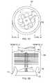
- FIGS. 10 and 1Dshow an exemplary embodiment of an apparatus 700 (top view shown in FIG. 1C and partial side-section view shown in FIG. 1D .
- the apparatus 700can be configured to provide a relatively smaller diameter muffler than conventional designs along with new benefits and outcomes.
- the apparatus 700includes a system of spaced rotor disks 702 that are supported on stationary tube spindle 718 by bearing assembly 716 and one or more suitable support fins 720 .
- the exemplary spinning rotor disks 702can be perforated with various optimized patterns of suitably shaped passageways 712 and/or louvers 714 for directing flow from inlet conduit 704 to shroud 706 and to an additional exhaust conduit to an interface with the atmosphere, e.g., such as bell 722 .
- Shroud 706further cools and collects growing droplets of condensate that disks 702 sling to the larger diameter of the periphery for collection through a collection component 708 including one or more pumps that deliver to a tube 710 for connection to a pump, e.g., such as the pump 186 of the system 180 .
- the kinetic energy from exhaust gases in the inlet conduit 704is transferred to features such as the perforations and/or louvers 714 to cause the exemplary droplet nucleation rotor disks 702 to spin for the combined purposes of cooling, e.g., converting acoustical wave energy into work for the spinning rotor disks 702 and slinging water droplets to the shroud 706 for collection.
- exhaust gasessuch as nitrogen, carbon dioxide, and/or oxygen are dried to the extent provided by water condensate removal through the tube 710 and are then rerouted to the exhaust bell 722 for very low pressure drop and accomplishment of combined exhaust noise quieting, water vapor cooling, and condensate collecting functions.
- the exhaust bell 722may be near or at some distance away from support fins 720 as may be optimized according to the vehicle application requirements.
- Additional functions as describedcan be used to provide for emergency blowdown of vapor or gases through the injector 116 and/or the injector 152 to the combustion chamber 158 and through one or more open exhaust valves 157 to the exhaust pipe 114 for delivery to assembly 700 .
- the apparatus 700provides a low clearance volume heat quenching system for blocking ignition and/or flame travel from inside of the inlet conduit 704 and similarly for blocking ignition sources outside of the bell 722 and effectively attenuating the heat and pressure of such emergency blowdown gases to protect anyone in the downstream zone of exhaust flow that would otherwise blast out of a conventional exhaust system.
- Equation 5depicts an exemplary case for the beneficial production and delivery of vapor or gaseous phase fuel constituents by the described armored fuel conversion systems, e.g., such as at times in which the system 180 is implemented without water additions.
- Equation 6depicts another example in which part of the endothermic energy ⁇ is produced by partial oxidation.
- such separated oxygenmay be delivered by filtration including membrane or pressure or temperature swing adsorption from atmospheric air.
- Oxygenmay also be produced from other sources such as the electrolysis of sulfuric acid solutions, e.g., such as in an electrolyzer 526 of a system 500 , as shown in U.S. patent application entitled “CHEMICAL FUEL CONDITIONING AND ACTIVATION”, filed on or before Mar. 15, 2013, which is incorporated in its entirety by reference as part of the disclosure in this patent document.
- vapors or gaseous fuel constituentscan be injected using an apparatus 600 , as shown in co-pending application 61/725,448.
- the apparatus 600can be implemented to provide, the armored delivery of the vapors or gaseous fuel constituents into the combustion chamber zone 618 . Description of the apparatus and its operation of the fuel injector apparatus 600 is provided in U.S. patent application entitled, “MECHANICAL MOTION AMPLIFICATION FOR NEW THERMODYNAMIC CYCLES”, filed on or before Mar. 15, 2013,, which is incorporated in its entirety by reference as part of the disclosure in this patent document.
- FIG. 2shows a diagram of a system 200 to provide further safety capabilities for converting a liquid fuel into a gaseous fuel substance.
- the system 200can be integrated in the exemplary systems 100 or 180 .
- the system 200includes heat exchanger circuits 208 and 209 structured to include tube structures that can comprise, for example, conductively coupled steel, stainless steel or super alloy tubing.
- the tube structuresmay be configured by placing the tube for the circuit 208 in a suitably larger tube, e.g., such as that of the circuit 209 , to develop an additional layer of armor.
- the tube structure of the circuit 209is designed as a considerably heavier-walled safety containment tube.
- the exemplary heat exchange circuits 208 and/or 209may be further contained in an inert substance, e.g., such as a fluid or a suitable fused salt medium 250 that is contained in an insulated layer 252 of pressure-rated vessel 210 .
- the zone 250can serve as an accumulator for storage of pressurized water, steam, a fuel reactant, or product constituents.
- reinforcement of the vessel 210is provided to armor the relatively small process events against damages that could cause leakage or malfunctions.
- Additional securitycan be provided by another barrier and collection assembly within the insulated layer 252 to provide substantially greater safety than conventional fuel management systems.
- the insulated layer assembly 252can be configured as an outer barrier jacket designed and constructed of an extremely tough stainless steel alloy foil or as a fiber-reinforced composite that provides for the collection and delivery via a conduit 254 of any leakage that may occur from the tube structures of the circuits 208 and/or 209 , or the containment tank 102 . For example, then the delivery of any such collected leakage would be made to a safe zone such as exhaust pipe 256 and/or conduit 258 .
- the exemplary exhaust pipe 256can be designed and constructed of heat and corrosion resistant materials that are suitable for long-term thermal cycling operations such as the containment conduit for hot exhaust gases from engines. For example, such exhaust gases may at times be highly aggressive oxidants, and at other times they may become acidic or reducing agents that are resisted by the exemplary exhaust pipe 256 .
- the exhaust pipe 256is structured to include a double-walled structure to provide insulation and prevent wind chill for retention of the heat in exhaust gases.
- Such exemplary double-walled constructionprovides another degree of containment and armor against adverse consequences, e.g., due to collisions and/or other types of damage.
- thermal shock, oxidation and reduction resistant, and superior heat containment capabilities of the exemplary exhaust pipe 256are utilized in the exemplary application of the system 200 to make exhaust pipe 256 a suitable receiver for any leakage that may occur in the case of crash impact damage or other failures of the tube structures of the heat exchanger circuits 208 and/or 209 and/or the vessel 210 .
- leakage that may occur in this critical circuitcan be drained safely into a relatively larger pressure blow-down capacity of conduit 256 , as shown.
- the relatively small volume of potentially dangerous fuel in the tubes of the circuits 208 and/or 209e.g., as compared to the much larger volume and heat and/or pressure dissipation capabilities of the exhaust tube 256 , provides a substantially greater degree of safety than conventional fuel delivery systems.
- the system 200can include other suitable blowdown piping units for heat and/or pressure dissipation.
- the system 200can include a separate tube such as the conduit 258 to provide a substantially greater degree of safety, e.g., than conventional fuel delivery systems.
- the conduit 258may provide a portion that aims potential leakage in a safer direction than may be found for an exhaust pipe, e.g., such as the exhaust pipe 256 .
- Additional safety featuresmay be provided by a dissipater cap 262 a , of the system 200 that is also designed and constructed to prevent the entry of rain, dust, and/or insects into the interior portions of the tube assembly 258 .
- conduit 258may include pressure and/or heat dissipating structures or packing contents 260 and an insulator system 262 , e.g., such as one or more layers or wraps or a double wall, to contain a foam or fibrous selection of thermal insulation to further improve safety capabilities.
- an insulator system 262e.g., such as one or more layers or wraps or a double wall, to contain a foam or fibrous selection of thermal insulation to further improve safety capabilities.
- FIG. 3Ashows a cross-sectioned view of the system 300 showing an exemplary high safety tube (e.g., such as the tube structure of the circuit 209 of system 200 in FIG. 2 ) interfaced with an armored tube 304 of the system 300 to deliver pressurized fuel into assembly 302 .
- the tube structure of the circuit 209may be further armored by the exemplary armored tube 304 , e.g., against damage and to provide thermal insulation for the flow of vapors and/or gases from fail-safe processes in the fuel conversion unit assemblies 110 and 112 .
- the armored fuel ignition system 300Delivery of the pressurized fuel into a combustion chamber 306 (of an engine) by the armored fuel ignition system 300 further offering enhanced safety by containment capabilities of the exhaust pipe 114 or 256 for protection of the fuel conversion unit assembly 112 coupled with the exemplary armored containment and improved fail-safe blowdown provisions of system 200 .
- the system 300can be configured to provide layers of fail-safe structural containment capabilities.
- the system 300can be structured to include pressure containment shell portions 308 A, 308 B, and 308 C, within which are pressure containing sub-assemblies 310 , 312 , and 314 , as shown in FIG. 3A .
- the system 300can also be configured to provide automatic actuation of over-pressure bleed down.
- the system 300can be structured to include a valve 316 interfaced with a port into the combustion chamber 306 to further improve overall system safety.
- valve 316is opened by such pressure.
- the valve 316is normally held closed by force exerted by permanent magnet 318 on armature 320 and thus on the connecting linkage to valve 316 to hold it closed against seat 322 .
- pressure over a safety limitforces the valve 316 open to relieve such pressure by allowing fuel to flow into the combustion chamber 306 and upon closure of throttle valve 126 through any exhaust valves to the exhaust pipe 114 or 256 or the conduit 258 .
- FIG. 3Bshows additional details of the exemplary embodiment of the system 300 shown in FIG. 3A , including the exemplary pressure assisted or over-pressure actuated outward opening valve 316 , the corresponding valve seat 322 , radial flow ports 324 , and annular passageway 326 between ignition electrodes 328 and 330 configured for providing rapid blowdown of fuel constituents into the combustion chamber 306 (e.g., in case of emergency).
- FIG. 3Balso shows the particularly rugged and multilayered armored construction within the exemplary case assembly 308 A, 308 B and 308 C of the system 300 to resist or administer fail-safe processes in instances of experiencing severe impact forces, e.g., such as those that might be present in a vehicle collision.
- a new or reprogrammed controller 122in response to alarms, e.g., such as fuel leakage detection or a crash impact indication typical of an event that would trigger deployment of air bags.
- the controller 122signals by wireless communication or connection through cables (e.g., such as cables 119 ) to trigger events including, but not limited to, the shutdown of the exemplary fuel ignition subsystem of the system 300 and closure of the valve 126 ; the shutoff of the pump 104 to stop fuel flow from the tank 102 ; and the actuation of the armature 320 , e.g., which is forced away from the magnet 318 to open the valve 316 and quickly bleed-down fluid between the tank 102 to the combustion chamber 306 .
- valvese.g., such as the valve 316
- exhaust containment pipee.g., such as the exhaust pipe 256
- Such emergency closure of the valve 126 by the, present embodiment for operation by the exemplary controller 122provides shutoff of air and thus the rapid elimination of oxygen that would support combustion and prevents the escape of any fuel constituent that might pass through an open intake valve.
- Implementation of the disclosed fuel systems, devices, and methodscan provide for improved fuel storage and utilization.
- Fuel storage and utilizationcan be achieved based on the disclosed features and techniques, e.g., including, but not limited to, application of the throttle valves (e.g., such as valve 126 of the systems 100 and/or 180 ), utilization of the heat and pressure dissipating capabilities of exhaust valves, exhaust manifolds, and exhaust pipe systems, the reduction or elimination of toxicity characteristics, and the armored production and delivery of fuel constituents with far more rapid escape characteristics of any potential leakage of vapors and gases compared to liquid fuels.
- Implementation of the disclosed fuel systems, devices, and methodsprovide improved fuel economy and engine performance.
- the disclosed systems, devices, and techniquescan be combined with the vaporization and/or gasification of conventional and/or new fuel compositions, e.g., including conversions that provide “net hydrogen” accomplishments that enable much greater public safety from harmful pollutants and greenhouse gas accumulation for additional public benefits.
- a method to provide a fuel for an engineincludes mixing formic acid with water to produce a liquid fuel, adding a fuel constituent in the liquid fuel, the fuel constituent being soluble in the liquid fuel, and converting, in a container having an interior formed of an armored material, the liquid fuel into a gaseous fuel substance using at least one of heat energy or electrical energy to pressurize the liquid fuel, the gaseous fuel substance exhibiting a higher pressure and lower density than that of the liquid fuel.
- the fuel constituentcan include urea, cellulose, starches, lipids, carbohydrates, amino acids, proteins, and other food products.
- the methodcan include mixing the formic acid with selected alcohols, e.g., such as methanol and/or ethanol.
- the mixing the formic acid with the selected alcoholcan be implemented with or without water.
- the formic acidis included in liquid fuel solutions to provide for denaturing of stored fuel and/or as an odorant and/or to serve with an electronic or optical detector as a more easily detected agent for early detection of incipient fuel leaks.
- the mixing the formic acidis not implemented and the formic acid serves as the liquid fuel.
- a system for producing a fuelcomprising:
- the armored materialincludes at least one of stainless steel or composite material including multilayers of at least one of stainless steel, carbon nanotubes, partially stabilized zirconia or spinel, or aluminum.
- the armored materialincludes at least one type of polymers including polyimides or Kevlar film or fiber.
- liquid fuel substanceincludes a hydrogen donor constituent, carbon donor constituent, or nitrogen donor constituent.
- a method for producing an alcohol fuelcomprising:
- the fuel constituentis selected from the group consisting of urea, cellulose, starches, lipids, carbohydrates, amino acids, proteins, and food products.
- the odorizing agentincludes at least one of wintergreen oil, methyl salicylate, or peppermint.
- a method to provide a fuel for an enginecomprising:
- the armored materialincludes at least one of stainless steel or composite material including multilayers of at least one of stainless steel, carbon nanotubes, partially stabilized zirconia or spinel, or aluminum.
- the armored materialincludes at least one type of polymers including polyimides or Kevlar film or fiber.
- odorizing agentincludes at least one of wintergreen oil, methyl salicylate, or peppermint.
- a method to provide a fuel for an enginecomprising:
- a method to provide a fuel for an enginecomprising:
Landscapes
- Chemical & Material Sciences (AREA)
- Oil, Petroleum & Natural Gas (AREA)
- Engineering & Computer Science (AREA)
- Chemical Kinetics & Catalysis (AREA)
- General Chemical & Material Sciences (AREA)
- Organic Chemistry (AREA)
- Health & Medical Sciences (AREA)
- Emergency Medicine (AREA)
- Liquid Carbonaceous Fuels (AREA)
- Life Sciences & Earth Sciences (AREA)
- Manufacturing & Machinery (AREA)
- Sustainable Development (AREA)
- Sustainable Energy (AREA)
- Electrochemistry (AREA)
Abstract
Description
CH4+Δ→C+2H2 (Eq. 1)
3H2+CO2→CH3OH+H2O (Eq. 2)
CH3OH+H2O+“C”+Δ→2CO+3H2 (Eq. 3)
C2H5OH+2H2O+“C”+Δ→3CO+5H2 (Eq. 4)
CH3OH+Δ→CO+2H2 (Eq. 5)
C2H5OH+0.5O2+Δ→2CO+3H2 (Eq. 6)
- a fuel storage unit to contain a liquid fuel substance stored at a low pressure;
- a fuel conversion unit to convert the liquid fuel substance into a gaseous fuel substance using at least one of heat energy or electrical energy to pressurize the liquid fuel substance, the fuel conversion unit including a tank having an interior formed of an armored material; and
- a fluid transfer unit including a low pressure pump to deliver the liquid fuel substance from the fuel storage unit to the fuel conversion unit,
- wherein the gaseous fuel substance exhibits a higher pressure and lower density than that of the liquid fuel substance.
- mixing an alcohol with water to produce a wet alcohol; and
- adding a fuel constituent in the wet alcohol, the fuel constituent being soluble in the wet alcohol.
- applying heat to a methane feedstock substance to produce hydrogen and a carbon substance, and
- reacting the hydrogen with carbon dioxide to create the methanol and water.
- mixing an alcohol with water to produce a wet alcohol;
- adding a fuel constituent in the wet alcohol to form a liquid fuel, the fuel constituent being soluble in the wet alcohol; and
- converting, in a container having an interior formed of an armored material, the liquid fuel into a gaseous fuel substance using at least one of heat energy or electrical energy to pressurize the liquid fuel, the gaseous fuel substance exhibiting a higher pressure and lower density than that of the liquid fuel.
- mixing an alcohol with water to produce a wet alcohol;
- suspending a fuel constituent in the wet alcohol to form a liquid fuel; and
- converting, in a container having an interior formed of an armored material, the liquid fuel into a gaseous fuel substance using at least one of heat energy or electrical energy to pressurize the liquid fuel, the gaseous fuel substance exhibiting a higher pressure and lower density than that of the liquid fuel.
- mixing formic acid with water to produce a liquid fuel;
- adding a fuel constituent in the liquid fuel, the fuel constituent being soluble in the liquid fuel; and
- converting, in a container having an interior formed of an armored material, the liquid fuel into a gaseous fuel substance using at least one of heat energy or electrical energy to pressurize the liquid fuel, the gaseous fuel substance exhibiting a higher pressure and lower density than that of the liquid fuel.
Claims (24)
Priority Applications (6)
| Application Number | Priority Date | Filing Date | Title |
|---|---|---|---|
| US13/831,748US9115325B2 (en) | 2012-11-12 | 2013-03-15 | Systems and methods for utilizing alcohol fuels |
| CN201380070297.2ACN104937082A (en) | 2012-11-12 | 2013-11-12 | Systems and methods for utilizing alcohol fuels |
| PCT/US2013/069746WO2014075100A1 (en) | 2012-11-12 | 2013-11-12 | Systems and methods for utilizing alcohol fuels |
| KR1020157015774AKR20150084058A (en) | 2012-11-12 | 2013-11-12 | Systems and methods for utilizing alcohol fuels |
| EP13854122.2AEP2917315A4 (en) | 2012-11-12 | 2013-11-12 | Systems and methods for utilizing alcohol fuels |
| US14/279,183US20150068123A1 (en) | 2012-11-12 | 2014-05-15 | Systems and methods for utilizing alcohol fuels |
Applications Claiming Priority (2)
| Application Number | Priority Date | Filing Date | Title |
|---|---|---|---|
| US201261725450P | 2012-11-12 | 2012-11-12 | |
| US13/831,748US9115325B2 (en) | 2012-11-12 | 2013-03-15 | Systems and methods for utilizing alcohol fuels |
Related Child Applications (1)
| Application Number | Title | Priority Date | Filing Date |
|---|---|---|---|
| US14/279,183Continuation-In-PartUS20150068123A1 (en) | 2012-11-12 | 2014-05-15 | Systems and methods for utilizing alcohol fuels |
Publications (2)
| Publication Number | Publication Date |
|---|---|
| US20140130401A1 US20140130401A1 (en) | 2014-05-15 |
| US9115325B2true US9115325B2 (en) | 2015-08-25 |
Family
ID=50680319
Family Applications (1)
| Application Number | Title | Priority Date | Filing Date |
|---|---|---|---|
| US13/831,748ActiveUS9115325B2 (en) | 2012-11-12 | 2013-03-15 | Systems and methods for utilizing alcohol fuels |
Country Status (5)
| Country | Link |
|---|---|
| US (1) | US9115325B2 (en) |
| EP (1) | EP2917315A4 (en) |
| KR (1) | KR20150084058A (en) |
| CN (1) | CN104937082A (en) |
| WO (1) | WO2014075100A1 (en) |
Cited By (1)
| Publication number | Priority date | Publication date | Assignee | Title |
|---|---|---|---|---|
| US20170159620A1 (en)* | 2014-07-04 | 2017-06-08 | Yuanjun GUO | Thermal energy power device and work-doing method therefor |
Families Citing this family (5)
| Publication number | Priority date | Publication date | Assignee | Title |
|---|---|---|---|---|
| DK177981B1 (en)* | 2013-09-03 | 2015-02-16 | Global Fuel Solution Sarl | Method and apparatus for increasing gaseous content of a hydrocarbon fuel |
| CN108258290B (en)* | 2018-01-31 | 2020-04-03 | 东北大学 | Method for preparing high-temperature proton exchange membrane with layer-by-layer assembly structure based on spin coating technology by doping phosphoric acid |
| US20220056587A1 (en)* | 2020-08-24 | 2022-02-24 | Portland State University | Method of fabricating and coating copper nanowires |
| CN112582644B (en)* | 2020-12-10 | 2025-04-08 | 中和智慧能源科技(深圳)有限公司 | A kind of alcohol hydrogen fuel power system and power generation device |
| CN115013207B (en)* | 2022-05-10 | 2023-12-29 | 哈尔滨工程大学 | Hybrid power system for hydrogen production based on high-low temperature reforming and control method |
Citations (245)
| Publication number | Priority date | Publication date | Assignee | Title |
|---|---|---|---|---|
| US1451384A (en) | 1920-04-19 | 1923-04-10 | Whyte John | Solenoid-controlled fuel injection and ignition valve |
| US1765237A (en) | 1928-02-17 | 1930-06-17 | Fred H King | Triple-cam-drive gasoline engine |
| US2255203A (en) | 1940-02-28 | 1941-09-09 | Wright Aeronautical Corp | Fuel injection spark plug |
| US3058453A (en) | 1960-02-15 | 1962-10-16 | Walker Mfg Co | Fuel injector-igniter |
| US3060912A (en) | 1960-02-15 | 1962-10-30 | Walker Mfg Co | Fuel injector-igniter |
| US3081758A (en) | 1960-05-02 | 1963-03-19 | Walker Mfg Co | Pressure actuated fuel injector |
| US3243335A (en) | 1963-03-13 | 1966-03-29 | Samuel P Faile | Ceramic product and process of producing it |
| GB1038490A (en) | 1963-02-18 | 1966-08-10 | Papst Hermann | Fuel injection nozzles for internal combustion engines |
| US3373724A (en) | 1964-02-10 | 1968-03-19 | Papst Hermann | Fuel injection and ignition device for internal combustion engines |
| US3391680A (en) | 1965-09-01 | 1968-07-09 | Physics Internat Company | Fuel injector-ignitor system for internal combustion engines |
| US3520961A (en) | 1967-05-12 | 1970-07-21 | Yuken Ind Co Ltd | Method for manufacturing ceramic articles |
| US3594877A (en) | 1969-10-24 | 1971-07-27 | Yuken Kogyo Co Ltd | Apparatus for manufacturing ceramic articles |
| US3608050A (en) | 1969-09-12 | 1971-09-21 | Union Carbide Corp | Production of single crystal sapphire by carefully controlled cooling from a melt of alumina |
| US3689293A (en) | 1970-07-08 | 1972-09-05 | Corning Glass Works | Mica glass-ceramics |
| US3926169A (en) | 1974-06-21 | 1975-12-16 | Fuel Injection Dev Corp | Combined fuel vapor injector and igniter system for internal combustion engines |
| US3931438A (en) | 1971-11-08 | 1976-01-06 | Corning Glass Works | Differential densification strengthening of glass-ceramics |
| US3960995A (en) | 1970-05-13 | 1976-06-01 | Kourkene Jacques P | Method for prestressing a body of ceramic material |
| US3976039A (en) | 1973-06-06 | 1976-08-24 | Regie Nationale Des Usines Renault | Internal combustion engine with stratified charge |
| US3997352A (en) | 1975-09-29 | 1976-12-14 | Corning Glass Works | Mica-spodumene glass-ceramic articles |
| US4045092A (en) | 1975-09-22 | 1977-08-30 | The Keller Corporation | Fuel composition and method of manufacture |
| US4066046A (en) | 1974-07-29 | 1978-01-03 | Mcalister Roy E | Method and apparatus for fuel injection-spark ignition system for an internal combustion engine |
| US4095580A (en) | 1976-10-22 | 1978-06-20 | The United States Of America As Represented By The United States Department Of Energy | Pulse-actuated fuel-injection spark plug |
| US4116389A (en) | 1976-12-27 | 1978-09-26 | Essex Group, Inc. | Electromagnetic fuel injection valve |
| US4122816A (en) | 1976-04-01 | 1978-10-31 | The United States Of America As Represented By The Administrator Of The National Aeronautics And Space Administration | Plasma igniter for internal combustion engine |
| US4135481A (en) | 1976-11-26 | 1979-01-23 | Cornell Research Foundation, Inc. | Exhaust gas recirculation pre-stratified charge |
| US4203393A (en) | 1979-01-04 | 1980-05-20 | Ford Motor Company | Plasma jet ignition engine and method |
| US4330732A (en) | 1980-03-14 | 1982-05-18 | Purification Sciences Inc. | Plasma ceramic coating to supply uniform sparking action in combustion engines |
| US4332223A (en) | 1980-08-29 | 1982-06-01 | Dalton James M | Plasma fuel ignitors |
| US4364342A (en) | 1980-10-01 | 1982-12-21 | Ford Motor Company | Ignition system employing plasma spray |
| US4364363A (en) | 1980-01-18 | 1982-12-21 | Toyota Jidosha Kogyo Kabushiki Kaisha | Electronically controlling, fuel injection method for internal combustion engine |
| US4368707A (en) | 1976-11-22 | 1983-01-18 | Fuel Injection Development Corporation | Adaptive charge forming system for controlling the air/fuel mixture supplied to an internal combustion engine |
| US4377455A (en) | 1981-07-22 | 1983-03-22 | Olin Corporation | V-Shaped sandwich-type cell with reticulate electodes |
| US4381740A (en) | 1980-05-05 | 1983-05-03 | Crocker Alfred J | Reciprocating engine |
| US4382189A (en) | 1979-05-25 | 1983-05-03 | Wilson John B | Hydrogen supplemented diesel electric locomotive |
| US4469160A (en) | 1981-12-23 | 1984-09-04 | United Technologies Corporation | Single crystal solidification using multiple seeds |
| US4483485A (en) | 1981-12-11 | 1984-11-20 | Aisan Kogyo kabuskiki Kaisha | Electromagnetic fuel injector |
| US4511612A (en) | 1981-08-21 | 1985-04-16 | Motoren-Und Turbinen-Union Munchen Gmbh | Multiple-layer wall for a hollow body and method for manufacturing same |
| US4528270A (en) | 1982-11-02 | 1985-07-09 | Kabushiki Kaisya Advance Kaihatsu Kenkyujo | Electrochemical method for detection and classification of microbial cell |
| US4536452A (en) | 1983-10-24 | 1985-08-20 | Corning Glass Works | Spontaneously-formed machinable glass-ceramics |
| JPS6123862A (en) | 1984-07-10 | 1986-02-01 | Toyota Motor Corp | Fuel injection controller |
| US4567857A (en) | 1980-02-26 | 1986-02-04 | The United States Of America As Represented By The Administrator Of The National Aeronautics And Space Administration | Combustion engine system |
| US4574037A (en) | 1983-04-12 | 1986-03-04 | Kanegafuchi Kagaku Kogyo Kabushiki Kaisha | Vertical type electrolytic cell and electrolytic process using the same |
| DE3443022A1 (en) | 1984-11-26 | 1986-05-28 | Walter Neumarkt am Wallersee Dolzer | Transistor ignition system |
| US4677960A (en) | 1984-12-31 | 1987-07-07 | Combustion Electromagnetics, Inc. | High efficiency voltage doubling ignition coil for CD system producing pulsed plasma type ignition |
| US4688538A (en) | 1984-12-31 | 1987-08-25 | Combustion Electromagnetics, Inc. | Rapid pulsed multiple pulse ignition and high efficiency power inverter with controlled output characteristics |
| US4700891A (en) | 1985-10-02 | 1987-10-20 | Robert Bosch Gmbh | Electromagnetically actuatable fuel injection valve |
| US4733646A (en) | 1986-04-30 | 1988-03-29 | Aisin Seiki Kabushiki Kaisha | Automotive ignition systems |
| US4736718A (en) | 1987-03-19 | 1988-04-12 | Linder Henry C | Combustion control system for internal combustion engines |
| US4742265A (en) | 1986-11-12 | 1988-05-03 | Ford Motor Company | Spark plug center electrode of alloy material including aluminum and chromium |
| US4760818A (en) | 1986-12-16 | 1988-08-02 | Allied Corporation | Vapor phase injector |
| US4760820A (en) | 1983-07-20 | 1988-08-02 | Luigi Tozzi | Plasma jet ignition apparatus |
| US4774914A (en) | 1985-09-24 | 1988-10-04 | Combustion Electromagnetics, Inc. | Electromagnetic ignition--an ignition system producing a large size and intense capacitive and inductive spark with an intense electromagnetic field feeding the spark |
| US4774919A (en) | 1986-09-08 | 1988-10-04 | Yamaha Hatsudoki Kabushiki Kaisha | Combustion chamber importing system for two-cycle diesel engine |
| US4834033A (en) | 1986-10-31 | 1989-05-30 | Larsen Melvin J | Apparatus and method for a balanced internal combustion engine coupled to a drive shaft |
| US4841925A (en) | 1986-12-22 | 1989-06-27 | Combustion Electromagnetics, Inc. | Enhanced flame ignition for hydrocarbon fuels |
| US4922883A (en) | 1987-10-29 | 1990-05-08 | Aisin Seiki Kabushiki Kaisha | Multi spark ignition system |
| EP0392594A2 (en) | 1989-04-10 | 1990-10-17 | EURON S.p.A. | Fuel injection nozzle |
| JPH02259268A (en) | 1989-03-30 | 1990-10-22 | Tonen Corp | Ultrasonic atomizer device for spark ignition engine |
| US4967708A (en) | 1987-09-17 | 1990-11-06 | Robert Bosch Gmbh | Fuel injection valve |
| US4977873A (en) | 1989-06-08 | 1990-12-18 | Clifford L. Elmore | Timing chamber ignition method and apparatus |
| US4982708A (en) | 1989-06-22 | 1991-01-08 | Robert Bosch Gmbh | Fuel injection nozzle for internal combustion engines |
| US5034852A (en) | 1989-11-06 | 1991-07-23 | Raytheon Company | Gasket for a hollow core module |
| US5055435A (en) | 1987-03-24 | 1991-10-08 | Ngk Insulators, Ltd. | Ceramic materials to be insert-cast |
| US5056496A (en) | 1989-03-14 | 1991-10-15 | Nippondenso Co., Ltd. | Ignition system of multispark type |
| US5069189A (en) | 1989-06-27 | 1991-12-03 | Sanshin Kogyo Kabushiki Kaisha | Fuel injector system for internal combustion engine |
| US5076223A (en) | 1990-03-30 | 1991-12-31 | Board Of Regents, The University Of Texas System | Miniature railgun engine ignitor |
| US5095742A (en) | 1990-08-24 | 1992-03-17 | Ford Motor Company | Determining crankshaft acceleration in an internal combustion engine |
| US5109817A (en) | 1990-11-13 | 1992-05-05 | Altronic, Inc. | Catalytic-compression timed ignition |
| US5131376A (en) | 1991-04-12 | 1992-07-21 | Combustion Electronics, Inc. | Distributorless capacitive discharge ignition system |
| US5150682A (en) | 1990-09-26 | 1992-09-29 | S.E.M.T. Pielstick | Method of monitoring emission of nitrogen oxides by an internal combustion engine |
| US5193515A (en) | 1991-03-12 | 1993-03-16 | Aisin Seiki Kabushiki Kaisha | Ignition system for an engine |
| US5207208A (en) | 1991-09-06 | 1993-05-04 | Combustion Electromagnetics Inc. | Integrated converter high power CD ignition |
| US5211142A (en) | 1990-03-30 | 1993-05-18 | Board Of Regents, The University Of Texas System | Miniature railgun engine ignitor |
| US5220901A (en) | 1991-10-09 | 1993-06-22 | Mitsubishi Denki Kabushiki Kaisha | Capacitor discharge ignition system with inductively extended discharge time |
| US5267601A (en) | 1988-11-10 | 1993-12-07 | Lanxide Technology Company, Lp | Method for forming a metal matrix composite body by an outside-in spontaneous infiltration process, and products produced thereby |
| US5297518A (en) | 1992-08-10 | 1994-03-29 | Cherry Mark A | Mass controlled compression timed ignition method and igniter |
| US5305360A (en) | 1993-02-16 | 1994-04-19 | Westinghouse Electric Corp. | Process for decontaminating a nuclear reactor coolant system |
| US5328094A (en) | 1993-02-11 | 1994-07-12 | General Motors Corporation | Fuel injector and check valve |
| US5343699A (en) | 1989-06-12 | 1994-09-06 | Mcalister Roy E | Method and apparatus for improved operation of internal combustion engines |
| US5377633A (en) | 1993-07-12 | 1995-01-03 | Siemens Automotive L.P. | Railplug direct injector/ignitor assembly |
| US5392745A (en) | 1987-02-20 | 1995-02-28 | Servojet Electric Systems, Ltd. | Expanding cloud fuel injecting system |
| US5421299A (en) | 1992-08-10 | 1995-06-06 | Cherry; Mark A. | Compression timed pre-chamber flame distributing igniter for internal combustion engines |
| US5435286A (en) | 1994-05-02 | 1995-07-25 | Cummins Engine Company, Inc. | Ball link assembly for vehicle engine drive trains |
| US5439532A (en) | 1992-06-30 | 1995-08-08 | Jx Crystals, Inc. | Cylindrical electric power generator using low bandgap thermophotovolatic cells and a regenerative hydrocarbon gas burner |
| EP0671555A1 (en) | 1992-02-13 | 1995-09-13 | Ngk Spark Plug Co., Ltd | Method for detecting deterioration of an air-fuel ratio sensor |
| US5456241A (en) | 1993-05-25 | 1995-10-10 | Combustion Electromagnetics, Inc. | Optimized high power high energy ignition system |
| US5475772A (en) | 1994-06-02 | 1995-12-12 | Honeywell Inc. | Spatial filter for improving polarization extinction ratio in a proton exchange wave guide device |
| JPH0849623A (en) | 1994-08-05 | 1996-02-20 | Kiyoshi Takeuchi | Liquid atomizer and manufacture thereof |
| US5497744A (en) | 1993-11-29 | 1996-03-12 | Toyota Jidosha Kabushiki Kaisha | Fuel injector with an integrated spark plug for a direct injection type engine |
| US5517961A (en) | 1995-02-27 | 1996-05-21 | Combustion Electromagnetics, Inc. | Engine with flow coupled spark discharge |
| US5531199A (en) | 1992-05-11 | 1996-07-02 | United Fuels Limited | Internal combustion engines |
| US5549746A (en) | 1993-09-24 | 1996-08-27 | General Electric Company | Solid state thermal conversion of polycrystalline alumina to sapphire using a seed crystal |
| US5584490A (en) | 1994-08-04 | 1996-12-17 | Nippon Gasket Co., Ltd. | Metal gasket with coolant contact areas |
| JPH08334077A (en) | 1995-06-08 | 1996-12-17 | Aisan Ind Co Ltd | Fuel injection device |
| US5588299A (en) | 1993-05-26 | 1996-12-31 | Simmonds Precision Engine Systems, Inc. | Electrostatic fuel injector body with igniter electrodes formed in the housing |
| US5605125A (en) | 1994-11-18 | 1997-02-25 | Yaoita; Yasuhito | Direct fuel injection stratified charge engine |
| US5607106A (en) | 1994-08-10 | 1997-03-04 | Cummins Engine Company | Low inertia, wear-resistant valve for engine fuel injection systems |
| US5662389A (en) | 1996-09-10 | 1997-09-02 | New York Air Brake Corporation | Variable load EP brake control system |
| US5676026A (en) | 1994-09-20 | 1997-10-14 | Honda Giken Kogyo Kabushiki Kaisha | Hydraulic pressure control system |
| US5699253A (en) | 1995-04-05 | 1997-12-16 | Ford Global Technologies, Inc. | Nonlinear dynamic transform for correction of crankshaft acceleration having torsional oscillations |
| US5702761A (en) | 1994-04-29 | 1997-12-30 | Mcdonnell Douglas Corporation | Surface protection of porous ceramic bodies |
| US5704321A (en) | 1996-05-29 | 1998-01-06 | The Trustees Of Princeton University | Traveling spark ignition system |
| US5715788A (en) | 1996-07-29 | 1998-02-10 | Cummins Engine Company, Inc. | Integrated fuel injector and ignitor assembly |
| US5738818A (en) | 1996-08-28 | 1998-04-14 | Northrop Grumman Corporation | Compression/injection molding of polymer-derived fiber reinforced ceramic matrix composite materials |
| US5746171A (en) | 1995-02-06 | 1998-05-05 | Yaoita; Yasuhito | Direct fuel injection stratified charge engine |
| US5767026A (en) | 1994-10-04 | 1998-06-16 | Agency Of Industrial Science And Technology | Silicon nitride ceramic and process for forming the same |
| US5797427A (en) | 1996-10-11 | 1998-08-25 | Buescher; Alfred J. | Fuel injector check valve |
| US5806581A (en) | 1995-12-21 | 1998-09-15 | Modine Manufacturing Company | Oil cooler with a retained, blow-out proof, and extrusion resistant gasket configuration |
| US5853175A (en) | 1996-09-30 | 1998-12-29 | Ishikawa Gasket Co., Ltd. | Cylinder head gasket with fluid flow path |
| US5863326A (en) | 1996-07-03 | 1999-01-26 | Cermet, Inc. | Pressurized skull crucible for crystal growth using the Czochralski technique |
| US5876659A (en) | 1993-06-25 | 1999-03-02 | Hitachi, Ltd. | Process for producing fiber reinforced composite |
| US5915272A (en) | 1993-08-02 | 1999-06-22 | Motorola Inc. | Method of detecting low compression pressure responsive to crankshaft acceleration measurement and apparatus therefor |
| US5941207A (en) | 1997-09-08 | 1999-08-24 | Ford Global Technologies, Inc. | Direct injection spark ignition engine |
| US5947091A (en) | 1995-11-14 | 1999-09-07 | Robert Bosch Gmbh | Fuel injection device for an internal combustion engine |
| US5983855A (en) | 1996-09-18 | 1999-11-16 | Robert Bosch Gmbh | Fuel injection valve with integrated spark plug |
| US6000628A (en) | 1998-04-06 | 1999-12-14 | Siemens Automotive Corporation | Fuel injector having differential piston for pressurizing fuel |
| US6017390A (en) | 1996-07-24 | 2000-01-25 | The Regents Of The University Of California | Growth of oriented crystals at polymerized membranes |
| US6026568A (en) | 1995-08-16 | 2000-02-22 | Northrop Grumman | High efficiency low-pollution engine |
| US6062498A (en) | 1998-04-27 | 2000-05-16 | Stanadyne Automotive Corp. | Fuel injector with at least one movable needle-guide |
| US6081183A (en) | 1998-04-24 | 2000-06-27 | Eaton Corporation | Resistor adapted for use in forced ventilation dynamic braking applications |
| US6085990A (en) | 1997-01-22 | 2000-07-11 | Daimlerchrysler Ag | Piezoelectric injector for fuel-injection systems of internal combustion engines |
| US6092507A (en) | 1996-08-08 | 2000-07-25 | Robert Bosch Gmbh | Control arrangement for a direct-injecting internal combustion engine |
| US6092501A (en) | 1997-05-20 | 2000-07-25 | Nissan Motor Co., Ltd. | Direct injection gasoline engine with stratified charge combustion and homogeneous charge combustion |
| US6093338A (en) | 1997-08-21 | 2000-07-25 | Kabushiki Kaisha Toyota Chuo Kenkyusho | Crystal-oriented ceramics, piezoelectric ceramics using the same, and methods for producing the same |
| US6102303A (en) | 1996-03-29 | 2000-08-15 | Siemens Automotive Corporation | Fuel injector with internal heater |
| US6138639A (en) | 1998-01-07 | 2000-10-31 | Nissan Motor Co., Ltd. | In-cylinder direct-injection spark-ignition engine |
| US6155212A (en) | 1989-06-12 | 2000-12-05 | Mcalister; Roy E. | Method and apparatus for operation of combustion engines |
| US6173913B1 (en) | 1999-08-25 | 2001-01-16 | Caterpillar Inc. | Ceramic check for a fuel injector |
| US6185355B1 (en) | 1998-09-01 | 2001-02-06 | Henry H. Hung | Process for making high yield, DC stable proton exchanged waveguide for active integrated optic devices |
| US6189522B1 (en) | 1998-02-12 | 2001-02-20 | Ngk Spark Plug Co., Ltd. | Waste-spark engine ignition |
| US6267307B1 (en) | 1997-12-12 | 2001-07-31 | Magneti Marelli France | Fuel injector with anti-scale ceramic coating for direct injection |
| US6318306B1 (en) | 1999-04-06 | 2001-11-20 | Nissan Motor Co., Ltd. | Internal combustion engine equipped with fuel reforming system |
| US6335065B1 (en) | 1994-11-14 | 2002-01-01 | Purdue Research Foundation | Process for slip casting textured tubular structures |
| US20020017573A1 (en) | 1994-06-06 | 2002-02-14 | Sturman Oded E. | Fuel injector with hydraulically controlled check valve |
| US6360721B1 (en) | 2000-05-23 | 2002-03-26 | Caterpillar Inc. | Fuel injector with independent control of check valve and fuel pressurization |
| US6378485B2 (en) | 1997-09-12 | 2002-04-30 | George D. Elliott | Electromagnetic fuel ram-injector and improved ignitor |
| US6386178B1 (en) | 2000-07-05 | 2002-05-14 | Visteon Global Technologies, Inc. | Electronic throttle control mechanism with gear alignment and mesh maintenance system |
| US20020084793A1 (en) | 2000-12-29 | 2002-07-04 | Hung Henry H. | Simultaneous testing of multiple optical circuits in substrate |
| US20020131756A1 (en) | 2000-10-16 | 2002-09-19 | Henry Hung | Variable optical attenuator |
| US20020131706A1 (en) | 2001-03-17 | 2002-09-19 | Micro Photonix Integration Corporation | Plural wavelength optical filter apparatus and method of manufacture |
| US20020131666A1 (en) | 2001-03-19 | 2002-09-19 | Henry Hung | Non-reciprocal phase shifter |
| US20020131673A1 (en) | 2001-03-17 | 2002-09-19 | Micro Photonix Integration Corporation | Dynamic optical wavelength balancer |
| US20020131171A1 (en) | 2000-10-16 | 2002-09-19 | Henry Hung | Optical fiber polarization independent non-reciprocal phase shifter |
| US20020131674A1 (en) | 2001-03-17 | 2002-09-19 | Micro Photonix Integration Corporation | Optical wavelength encoded multiple access arrangement |
| US6455173B1 (en) | 1997-12-09 | 2002-09-24 | Gillion Herman Marijnissen | Thermal barrier coating ceramic structure |
| US6453660B1 (en) | 2001-01-18 | 2002-09-24 | General Electric Company | Combustor mixer having plasma generating nozzle |
| US20020141692A1 (en) | 2000-10-16 | 2002-10-03 | Henry Hung | Optical network with dynamic balancing |
| US20020150375A1 (en) | 2001-04-13 | 2002-10-17 | Hung Henry H. | Crimp for providing hermetic seal for optical fiber |
| US20020151113A1 (en) | 2001-04-13 | 2002-10-17 | Hung Henry H. | Apparatus and method for suppressing false resonances in fiber optic modulators |
| US6478007B2 (en) | 2000-11-24 | 2002-11-12 | Toyota Jidosha Kabushiki Kaisha | In-cylinder-injection internal combustion engine and method of controlling in-cylinder-injection internal combustion engine |
| US6506336B1 (en) | 1999-09-01 | 2003-01-14 | Corning Incorporated | Fabrication of ultra-thinwall cordierite structures |
| US6517011B1 (en) | 2000-06-13 | 2003-02-11 | Caterpillar Inc | Fuel injector with pressurized fuel reverse flow check valve |
| US6532315B1 (en) | 2000-10-06 | 2003-03-11 | Donald J. Lenkszus | Variable chirp optical modulator having different length electrodes |
| US20030047626A1 (en) | 2000-07-28 | 2003-03-13 | Martin Maier | Fuel injection valve |
| US20030047627A1 (en) | 2000-08-10 | 2003-03-13 | Hubert Stier | Fuel injection valve |
| US6561168B2 (en) | 2001-03-29 | 2003-05-13 | Denso Corporation | Fuel injection device having heater |
| US20030102386A1 (en) | 2000-08-10 | 2003-06-05 | Thomas Sebastian | Fuel injection valve |
| US6578775B2 (en) | 2001-03-30 | 2003-06-17 | Denso Corporation | Fuel injector |
| US6584244B2 (en) | 2001-03-17 | 2003-06-24 | Donald J. Lenkszus | Switched filter for optical applications |
| US6583901B1 (en) | 2000-02-23 | 2003-06-24 | Henry Hung | Optical communications system with dynamic channel allocation |
| US6587239B1 (en) | 2000-02-23 | 2003-07-01 | Henry Hung | Optical fiber network having increased channel capacity |
| US6615899B1 (en) | 2002-07-12 | 2003-09-09 | Honeywell International Inc. | Method of casting a metal article having a thinwall |
| US6619269B1 (en) | 1999-11-27 | 2003-09-16 | Robert Bosch Gmbh | Fuel injector |
| US6626164B2 (en) | 2001-02-14 | 2003-09-30 | Mazda Motor Corporation | Automotive four-cycle engine |
| US6663027B2 (en) | 2000-12-11 | 2003-12-16 | Kimberly-Clark Worldwide, Inc. | Unitized injector modified for ultrasonically stimulated operation |
| US6672277B2 (en) | 2000-03-29 | 2004-01-06 | Mazda Motor Corporation | Direct-injection spark ignition engine |
| US6700306B2 (en) | 2001-02-27 | 2004-03-02 | Kyocera Corporation | Laminated piezo-electric device |
| US6705274B2 (en) | 2001-06-26 | 2004-03-16 | Nissan Motor Co., Ltd. | In-cylinder direct injection spark-ignition internal combustion engine |
| US20040060304A1 (en)* | 2002-09-27 | 2004-04-01 | The Regents Of The University Of California | Lightweight cryogenic-compatible pressure vessels for vehicular fuel storage |
| US6722340B1 (en) | 1999-06-11 | 2004-04-20 | Hitachi, Ltd. | Cylinder injection engine and fuel injection nozzle used for the engine |
| US20040075000A1 (en) | 2001-10-04 | 2004-04-22 | Wolfgang-Manfred Ruehle | Fuel injection valve |
| US6725826B2 (en) | 2000-09-01 | 2004-04-27 | Robert Bosch Gmbh | Mixture adaptation method for internal combustion engines with direct gasoline injection |
| US6745744B2 (en) | 2000-06-08 | 2004-06-08 | Szymon Suckewer | Combustion enhancement system and method |
| US6749043B2 (en) | 2001-10-22 | 2004-06-15 | General Electric Company | Locomotive brake resistor cooling apparatus |
| US6756140B1 (en) | 1989-06-12 | 2004-06-29 | Mcalister Roy E. | Energy conversion system |
| US6763811B1 (en) | 2003-01-10 | 2004-07-20 | Ronnell Company, Inc. | Method and apparatus to enhance combustion of a fuel |
| US6766965B2 (en) | 2001-08-31 | 2004-07-27 | Siemens Automotive Corporation | Twin tube hydraulic compensator for a fuel injector |
| US20040164175A1 (en) | 2002-02-05 | 2004-08-26 | Walter Maeurer | Fuel-injection valve |
| DE10308914A1 (en) | 2003-02-28 | 2004-09-09 | Robert Bosch Gmbh | Fuel injection valve for internal combustion engine has armature surrounding fuel injection needle with flange welded to it and incorporates damping ring between flange and bottom of armature |
| JP2004324613A (en) | 2003-04-28 | 2004-11-18 | Nissan Motor Co Ltd | Prime mover temperature controller |
| US6832588B2 (en) | 2001-12-06 | 2004-12-21 | Robert Bosch Gmbh | Fuel injector-spark plug combination |
| US6845920B2 (en) | 2001-04-19 | 2005-01-25 | Denso Corporation | Piezoelectric element and injector using the same |
| US6851413B1 (en) | 2003-01-10 | 2005-02-08 | Ronnell Company, Inc. | Method and apparatus to increase combustion efficiency and to reduce exhaust gas pollutants from combustion of a fuel |
| US6871630B2 (en) | 2001-12-06 | 2005-03-29 | Robert Bosch Gmbh | Combined fuel injection valve/ignition plug |
| US6883490B2 (en) | 2000-02-11 | 2005-04-26 | Michael E. Jayne | Plasma ignition for direct injected internal combustion engines |
| US6899076B2 (en) | 2002-09-27 | 2005-05-31 | Kubota Corporation | Swirl chamber used in association with a combustion chamber for diesel engines |
| US6904893B2 (en) | 2002-07-11 | 2005-06-14 | Toyota Jidosha Kabushiki Kaisha | Fuel injection method in fuel injector |
| US6912998B1 (en) | 2004-03-10 | 2005-07-05 | Cummins Inc. | Piezoelectric fuel injection system with rate shape control and method of controlling same |
| US6925983B2 (en) | 2001-12-06 | 2005-08-09 | Robert Bosch Gmbh | Fuel injection valve spark plug combination |
| US6940213B1 (en) | 1999-03-04 | 2005-09-06 | Robert Bosch Gmbh | Piezoelectric actuator |
| US20050255011A1 (en) | 2004-05-12 | 2005-11-17 | Greathouse Michael W | Plasma fuel reformer with one-piece body |
| US6976683B2 (en) | 2003-08-25 | 2005-12-20 | Elring Klinger Ag | Cylinder head gasket |
| US20060005738A1 (en) | 2001-03-27 | 2006-01-12 | Kumar Ajith K | Railroad vehicle with energy regeneration |
| US20060005739A1 (en) | 2001-03-27 | 2006-01-12 | Kumar Ajith K | Railroad system comprising railroad vehicle with energy regeneration |
| US6994073B2 (en) | 2003-10-31 | 2006-02-07 | Woodward Governor Company | Method and apparatus for detecting ionization signal in diesel and dual mode engines with plasma discharge system |
| US7007658B1 (en) | 2002-06-21 | 2006-03-07 | Smartplugs Corporation | Vacuum shutdown system |
| US7013863B2 (en) | 1998-06-22 | 2006-03-21 | Hitachi, Ltd. | Cylinder injection type internal combustion engine, control method for internal combustion engine, and fuel injection valve |
| US7025358B2 (en) | 2002-04-04 | 2006-04-11 | Japan Metal Gasket Co., Ltd. | Metallic gasket |
| US7032845B2 (en) | 2002-02-26 | 2006-04-25 | Robert Bosch Gmbh | Fuel injection valve |
| US7070126B2 (en) | 2001-05-09 | 2006-07-04 | Caterpillar Inc. | Fuel injector with non-metallic tip insulator |
| US20060144693A1 (en)* | 2005-01-04 | 2006-07-06 | Villalobos Victor M | Arc-hydrolysis fuel generator with energy recovery |
| US7073480B2 (en) | 2004-10-13 | 2006-07-11 | Nissan Motor Co., Ltd. | Exhaust emission control apparatus and method for internal combustion engine |
| US7086376B2 (en) | 2000-02-28 | 2006-08-08 | Orbital Engine Company (Australia) Pty Limited | Combined fuel injection and ignition means |
| US7104246B1 (en) | 2005-04-07 | 2006-09-12 | Smart Plug, Inc. | Spark ignition modifier module and method |
| US7104250B1 (en) | 2005-09-02 | 2006-09-12 | Ford Global Technologies, Llc | Injection spray pattern for direct injection spark ignition engines |
| US7131426B2 (en) | 2001-11-27 | 2006-11-07 | Bosch Corporation | Fluid flow rate control valve, anchor for mover and fuel injection system |
| US7140347B2 (en) | 2004-03-04 | 2006-11-28 | Kawasaki Jukogyo Kabushiki Kaisha | Swirl forming device in combustion engine |
| KR20070026296A (en) | 2003-08-26 | 2007-03-08 | 쿄세라 코포레이션 | Silicon nitride sintered body, a manufacturing method thereof, and a member for molten metal using the same, a member for wear resistance |
| DE102005060139A1 (en) | 2005-12-16 | 2007-06-28 | Giese, Erhard, Dr. | Spark plug for petrol engine, has insulating body inserted into screwing body and guiding central electrode, which has borehole that interacts with combustion chamber, and fiber optic pressure sensor that is inserted into borehole |
| US7249578B2 (en) | 2004-10-30 | 2007-07-31 | Volkswagen Ag | Cylinder head gasket for use in an internal combustion engine and internal combustion engine equipped therewith |
| US7255290B2 (en) | 2004-06-14 | 2007-08-14 | Charles B. Bright | Very high speed rate shaping fuel injector |
| US20070189114A1 (en) | 2004-04-16 | 2007-08-16 | Crenano Gmbh | Multi-chamber supercavitation reactor |
| US7272487B2 (en) | 2005-07-14 | 2007-09-18 | Ford Global Technologies, Llc | Method for monitoring combustion stability of an internal combustion engine |
| US7278392B2 (en) | 2005-01-07 | 2007-10-09 | Volkswagen Ag | Method for operating a hybrid vehicle and hybrid vehicle with a multi-cylinder internal combustion engine coupled to an electric motor |
| US20070283927A1 (en) | 2006-06-12 | 2007-12-13 | Nissan Motor Co., Ltd. | Fuel injection system of internal combustion engine, and fuel injection method of the internal combustion engine |
| WO2008017576A1 (en) | 2006-08-08 | 2008-02-14 | Siemens Aktiengesellschaft | Fuel injection valve with ignition |
| US20080035116A1 (en) | 2004-12-06 | 2008-02-14 | Martin Scheffel | Fuel Injector |
| US7367319B2 (en) | 2005-11-16 | 2008-05-06 | Gm Global Technology Operations, Inc. | Method and apparatus to determine magnitude of combustion chamber deposits |
| US7395146B2 (en) | 2005-03-30 | 2008-07-01 | Toyota Jidosha Kabushiki Kaisha | Fuel injection control apparatus for internal combustion engine |
| KR20080073635A (en) | 2005-04-28 | 2008-08-11 | 히타치 긴조쿠 가부시키가이샤 | Silicon nitride substrate, its manufacturing method, silicon nitride wiring board and semiconductor module using same |
| US7418940B1 (en) | 2007-08-30 | 2008-09-02 | Ford Global Technologies, Llc | Fuel injector spray pattern for direct injection spark ignition engines |
| US7422166B2 (en) | 2005-11-02 | 2008-09-09 | Delphi Technologies, Inc. | Fuel injector having a separable armature and pintle |
| EP1972606A1 (en) | 2007-02-26 | 2008-09-24 | Ngk Insulators, Ltd. | Crystallographically-oriented ceramic |
| US7481043B2 (en) | 2003-12-18 | 2009-01-27 | Toyota Jidosha Kabushiki Kaisha | Plasma injector, exhaust gas purifying system and method for injecting reducing agent |
| US20090093951A1 (en) | 2007-10-05 | 2009-04-09 | Mckay Daniel L | Method for determination of Covariance of Indicated Mean Effective Pressure from crankshaft misfire acceleration |
| US7540271B2 (en) | 2007-04-25 | 2009-06-02 | Advanced Global Equities And Intellectual Properties, Inc. | Fuel injection lubrication mechanism for continuous self lubrication of a fuel injector |
| US7554250B2 (en) | 2005-12-19 | 2009-06-30 | Denso Corporation | Laminate-type piezoelectric element and method of producing the same |
| US7625531B1 (en) | 2005-09-01 | 2009-12-01 | Los Alamos National Security, Llc | Fuel injector utilizing non-thermal plasma activation |
| US7626315B2 (en) | 2005-06-10 | 2009-12-01 | Denso Corporation | Piezo-injector driving apparatus |
| US7650873B2 (en) | 2006-07-05 | 2010-01-26 | Advanced Propulsion Technologies, Inc. | Spark ignition and fuel injector system for an internal combustion engine |
| US7703775B2 (en) | 2004-10-29 | 2010-04-27 | Nippon Leakless Industry Co., Ltd | Metal gasket for cylinder head |
| US7707832B2 (en) | 2005-12-05 | 2010-05-04 | Snecma | Device for injecting a mixture of air and fuel, and a combustion chamber and turbomachine provided with such a device |
| US7714483B2 (en) | 2008-03-20 | 2010-05-11 | Caterpillar Inc. | Fuel injector having piezoelectric actuator with preload control element and method |
| US7728489B2 (en) | 2006-09-27 | 2010-06-01 | Robert Bosch Gmbh | Piezoelectric actuator with a sheath, for disposition in a piezoelectric injector |
| US7849833B2 (en) | 2008-02-28 | 2010-12-14 | Denso Corporation | Engine head structure |
| US7886993B2 (en) | 2002-04-04 | 2011-02-15 | Siemens Aktiengesellschaft | Injection valve |
| US20110036309A1 (en) | 2008-01-07 | 2011-02-17 | Mcalister Technologies, Llc | Method and system of thermochemical regeneration to provide oxygenated fuel, for example, with fuel-cooled fuel injectors |
| US20110048374A1 (en) | 2008-01-07 | 2011-03-03 | Mcalister Technologies, Llc | Methods and systems for reducing the formation of oxides of nitrogen during combustion in engines |
| US7918212B2 (en) | 2008-10-08 | 2011-04-05 | GM Global Technology Operations LLC | Method and control system for controlling an engine function based on crankshaft acceleration |
| US7942136B2 (en) | 2005-06-06 | 2011-05-17 | Fernando Lepsch | Fuel-heating assembly and method for the pre-heating of fuel an internal combustion engine |
| US8069836B2 (en) | 2009-03-11 | 2011-12-06 | Point-Man Aeronautics, Llc | Fuel injection stream parallel opposed multiple electrode spark gap for fuel injector |
| US20120227389A1 (en)* | 2008-04-16 | 2012-09-13 | Hinderks M V | Reciprocating machine & other devices |
| US20120264662A1 (en)* | 2011-03-24 | 2012-10-18 | Dibiase Stephen A | Functionalized monomers |
| US20120297775A1 (en)* | 2011-05-25 | 2012-11-29 | Flexenergy, Inc. | Integrated gasifier power plant |
| US8686171B2 (en)* | 2006-08-04 | 2014-04-01 | Mcneff Research Consultants, Inc. | Methods and apparatus for producing alkyl esters from lipid feed stocks and systems including same |
Family Cites Families (7)
| Publication number | Priority date | Publication date | Assignee | Title |
|---|---|---|---|---|
| CA2087459C (en)* | 1992-01-23 | 2000-03-21 | Jack Lewis Stolz | Internal combustion engine with cooling of intake air using refrigeration of liquefied fuel gas |
| WO2002090750A1 (en)* | 2001-05-03 | 2002-11-14 | Was Diesel Now Gas Pty Ltd | Fuel delivery system |
| CA2362881C (en)* | 2001-11-30 | 2004-01-27 | Westport Research Inc. | Method and apparatus for delivering pressurized gas |
| CA2523732C (en)* | 2005-11-10 | 2007-09-18 | Westport Research Inc. | System and method for delivering a pressurized gas from a cryogenic storage vessel |
| US20080047502A1 (en)* | 2006-08-23 | 2008-02-28 | Michael Russo | Hybrid Cycle Electrolysis Power System with Hydrogen & Oxygen Energy Storage |
| US7628137B1 (en)* | 2008-01-07 | 2009-12-08 | Mcalister Roy E | Multifuel storage, metering and ignition system |
| WO2011100721A2 (en)* | 2010-02-13 | 2011-08-18 | Mcalister Roy E | Oxygenated fuel |
- 2013
- 2013-03-15USUS13/831,748patent/US9115325B2/enactiveActive
- 2013-11-12EPEP13854122.2Apatent/EP2917315A4/ennot_activeWithdrawn
- 2013-11-12WOPCT/US2013/069746patent/WO2014075100A1/enactiveApplication Filing
- 2013-11-12KRKR1020157015774Apatent/KR20150084058A/ennot_activeCeased
- 2013-11-12CNCN201380070297.2Apatent/CN104937082A/enactivePending
Patent Citations (250)
| Publication number | Priority date | Publication date | Assignee | Title |
|---|---|---|---|---|
| US1451384A (en) | 1920-04-19 | 1923-04-10 | Whyte John | Solenoid-controlled fuel injection and ignition valve |
| US1765237A (en) | 1928-02-17 | 1930-06-17 | Fred H King | Triple-cam-drive gasoline engine |
| US2255203A (en) | 1940-02-28 | 1941-09-09 | Wright Aeronautical Corp | Fuel injection spark plug |
| US3058453A (en) | 1960-02-15 | 1962-10-16 | Walker Mfg Co | Fuel injector-igniter |
| US3060912A (en) | 1960-02-15 | 1962-10-30 | Walker Mfg Co | Fuel injector-igniter |
| US3081758A (en) | 1960-05-02 | 1963-03-19 | Walker Mfg Co | Pressure actuated fuel injector |
| GB1038490A (en) | 1963-02-18 | 1966-08-10 | Papst Hermann | Fuel injection nozzles for internal combustion engines |
| US3243335A (en) | 1963-03-13 | 1966-03-29 | Samuel P Faile | Ceramic product and process of producing it |
| US3373724A (en) | 1964-02-10 | 1968-03-19 | Papst Hermann | Fuel injection and ignition device for internal combustion engines |
| US3391680A (en) | 1965-09-01 | 1968-07-09 | Physics Internat Company | Fuel injector-ignitor system for internal combustion engines |
| US3520961A (en) | 1967-05-12 | 1970-07-21 | Yuken Ind Co Ltd | Method for manufacturing ceramic articles |
| US3608050A (en) | 1969-09-12 | 1971-09-21 | Union Carbide Corp | Production of single crystal sapphire by carefully controlled cooling from a melt of alumina |
| US3594877A (en) | 1969-10-24 | 1971-07-27 | Yuken Kogyo Co Ltd | Apparatus for manufacturing ceramic articles |
| US3960995A (en) | 1970-05-13 | 1976-06-01 | Kourkene Jacques P | Method for prestressing a body of ceramic material |
| US3689293A (en) | 1970-07-08 | 1972-09-05 | Corning Glass Works | Mica glass-ceramics |
| US3931438A (en) | 1971-11-08 | 1976-01-06 | Corning Glass Works | Differential densification strengthening of glass-ceramics |
| US3976039A (en) | 1973-06-06 | 1976-08-24 | Regie Nationale Des Usines Renault | Internal combustion engine with stratified charge |
| US3926169A (en) | 1974-06-21 | 1975-12-16 | Fuel Injection Dev Corp | Combined fuel vapor injector and igniter system for internal combustion engines |
| US4066046A (en) | 1974-07-29 | 1978-01-03 | Mcalister Roy E | Method and apparatus for fuel injection-spark ignition system for an internal combustion engine |
| US4045092A (en) | 1975-09-22 | 1977-08-30 | The Keller Corporation | Fuel composition and method of manufacture |
| US3997352A (en) | 1975-09-29 | 1976-12-14 | Corning Glass Works | Mica-spodumene glass-ceramic articles |
| US4122816A (en) | 1976-04-01 | 1978-10-31 | The United States Of America As Represented By The Administrator Of The National Aeronautics And Space Administration | Plasma igniter for internal combustion engine |
| US4095580A (en) | 1976-10-22 | 1978-06-20 | The United States Of America As Represented By The United States Department Of Energy | Pulse-actuated fuel-injection spark plug |
| US4368707A (en) | 1976-11-22 | 1983-01-18 | Fuel Injection Development Corporation | Adaptive charge forming system for controlling the air/fuel mixture supplied to an internal combustion engine |
| US4135481A (en) | 1976-11-26 | 1979-01-23 | Cornell Research Foundation, Inc. | Exhaust gas recirculation pre-stratified charge |
| US4116389A (en) | 1976-12-27 | 1978-09-26 | Essex Group, Inc. | Electromagnetic fuel injection valve |
| US4203393A (en) | 1979-01-04 | 1980-05-20 | Ford Motor Company | Plasma jet ignition engine and method |
| US4382189A (en) | 1979-05-25 | 1983-05-03 | Wilson John B | Hydrogen supplemented diesel electric locomotive |
| US4364363A (en) | 1980-01-18 | 1982-12-21 | Toyota Jidosha Kogyo Kabushiki Kaisha | Electronically controlling, fuel injection method for internal combustion engine |
| US4567857A (en) | 1980-02-26 | 1986-02-04 | The United States Of America As Represented By The Administrator Of The National Aeronautics And Space Administration | Combustion engine system |
| US4330732A (en) | 1980-03-14 | 1982-05-18 | Purification Sciences Inc. | Plasma ceramic coating to supply uniform sparking action in combustion engines |
| US4381740A (en) | 1980-05-05 | 1983-05-03 | Crocker Alfred J | Reciprocating engine |
| US4332223A (en) | 1980-08-29 | 1982-06-01 | Dalton James M | Plasma fuel ignitors |
| US4364342A (en) | 1980-10-01 | 1982-12-21 | Ford Motor Company | Ignition system employing plasma spray |
| US4377455A (en) | 1981-07-22 | 1983-03-22 | Olin Corporation | V-Shaped sandwich-type cell with reticulate electodes |
| US4511612A (en) | 1981-08-21 | 1985-04-16 | Motoren-Und Turbinen-Union Munchen Gmbh | Multiple-layer wall for a hollow body and method for manufacturing same |
| US4483485A (en) | 1981-12-11 | 1984-11-20 | Aisan Kogyo kabuskiki Kaisha | Electromagnetic fuel injector |
| US4469160A (en) | 1981-12-23 | 1984-09-04 | United Technologies Corporation | Single crystal solidification using multiple seeds |
| US4528270A (en) | 1982-11-02 | 1985-07-09 | Kabushiki Kaisya Advance Kaihatsu Kenkyujo | Electrochemical method for detection and classification of microbial cell |
| US4574037A (en) | 1983-04-12 | 1986-03-04 | Kanegafuchi Kagaku Kogyo Kabushiki Kaisha | Vertical type electrolytic cell and electrolytic process using the same |
| US4760820A (en) | 1983-07-20 | 1988-08-02 | Luigi Tozzi | Plasma jet ignition apparatus |
| US4536452A (en) | 1983-10-24 | 1985-08-20 | Corning Glass Works | Spontaneously-formed machinable glass-ceramics |
| JPS6123862A (en) | 1984-07-10 | 1986-02-01 | Toyota Motor Corp | Fuel injection controller |
| DE3443022A1 (en) | 1984-11-26 | 1986-05-28 | Walter Neumarkt am Wallersee Dolzer | Transistor ignition system |
| US4677960A (en) | 1984-12-31 | 1987-07-07 | Combustion Electromagnetics, Inc. | High efficiency voltage doubling ignition coil for CD system producing pulsed plasma type ignition |
| US4688538A (en) | 1984-12-31 | 1987-08-25 | Combustion Electromagnetics, Inc. | Rapid pulsed multiple pulse ignition and high efficiency power inverter with controlled output characteristics |
| US4774914A (en) | 1985-09-24 | 1988-10-04 | Combustion Electromagnetics, Inc. | Electromagnetic ignition--an ignition system producing a large size and intense capacitive and inductive spark with an intense electromagnetic field feeding the spark |
| US4700891A (en) | 1985-10-02 | 1987-10-20 | Robert Bosch Gmbh | Electromagnetically actuatable fuel injection valve |
| US4733646A (en) | 1986-04-30 | 1988-03-29 | Aisin Seiki Kabushiki Kaisha | Automotive ignition systems |
| US4774919A (en) | 1986-09-08 | 1988-10-04 | Yamaha Hatsudoki Kabushiki Kaisha | Combustion chamber importing system for two-cycle diesel engine |
| US4834033A (en) | 1986-10-31 | 1989-05-30 | Larsen Melvin J | Apparatus and method for a balanced internal combustion engine coupled to a drive shaft |
| US4742265A (en) | 1986-11-12 | 1988-05-03 | Ford Motor Company | Spark plug center electrode of alloy material including aluminum and chromium |
| US4760818A (en) | 1986-12-16 | 1988-08-02 | Allied Corporation | Vapor phase injector |
| US4841925A (en) | 1986-12-22 | 1989-06-27 | Combustion Electromagnetics, Inc. | Enhanced flame ignition for hydrocarbon fuels |
| US5392745A (en) | 1987-02-20 | 1995-02-28 | Servojet Electric Systems, Ltd. | Expanding cloud fuel injecting system |
| US4736718A (en) | 1987-03-19 | 1988-04-12 | Linder Henry C | Combustion control system for internal combustion engines |
| US5055435A (en) | 1987-03-24 | 1991-10-08 | Ngk Insulators, Ltd. | Ceramic materials to be insert-cast |
| US4967708A (en) | 1987-09-17 | 1990-11-06 | Robert Bosch Gmbh | Fuel injection valve |
| US4922883A (en) | 1987-10-29 | 1990-05-08 | Aisin Seiki Kabushiki Kaisha | Multi spark ignition system |
| US5267601A (en) | 1988-11-10 | 1993-12-07 | Lanxide Technology Company, Lp | Method for forming a metal matrix composite body by an outside-in spontaneous infiltration process, and products produced thereby |
| US5056496A (en) | 1989-03-14 | 1991-10-15 | Nippondenso Co., Ltd. | Ignition system of multispark type |
| JPH02259268A (en) | 1989-03-30 | 1990-10-22 | Tonen Corp | Ultrasonic atomizer device for spark ignition engine |
| EP0392594A2 (en) | 1989-04-10 | 1990-10-17 | EURON S.p.A. | Fuel injection nozzle |
| US4977873A (en) | 1989-06-08 | 1990-12-18 | Clifford L. Elmore | Timing chamber ignition method and apparatus |
| US6155212A (en) | 1989-06-12 | 2000-12-05 | Mcalister; Roy E. | Method and apparatus for operation of combustion engines |
| US6756140B1 (en) | 1989-06-12 | 2004-06-29 | Mcalister Roy E. | Energy conversion system |
| US5343699A (en) | 1989-06-12 | 1994-09-06 | Mcalister Roy E | Method and apparatus for improved operation of internal combustion engines |
| US4982708A (en) | 1989-06-22 | 1991-01-08 | Robert Bosch Gmbh | Fuel injection nozzle for internal combustion engines |
| US5069189A (en) | 1989-06-27 | 1991-12-03 | Sanshin Kogyo Kabushiki Kaisha | Fuel injector system for internal combustion engine |
| US5034852A (en) | 1989-11-06 | 1991-07-23 | Raytheon Company | Gasket for a hollow core module |
| US5211142A (en) | 1990-03-30 | 1993-05-18 | Board Of Regents, The University Of Texas System | Miniature railgun engine ignitor |
| US5076223A (en) | 1990-03-30 | 1991-12-31 | Board Of Regents, The University Of Texas System | Miniature railgun engine ignitor |
| US5095742A (en) | 1990-08-24 | 1992-03-17 | Ford Motor Company | Determining crankshaft acceleration in an internal combustion engine |
| US5150682A (en) | 1990-09-26 | 1992-09-29 | S.E.M.T. Pielstick | Method of monitoring emission of nitrogen oxides by an internal combustion engine |
| US5109817A (en) | 1990-11-13 | 1992-05-05 | Altronic, Inc. | Catalytic-compression timed ignition |
| US5193515A (en) | 1991-03-12 | 1993-03-16 | Aisin Seiki Kabushiki Kaisha | Ignition system for an engine |
| US5131376A (en) | 1991-04-12 | 1992-07-21 | Combustion Electronics, Inc. | Distributorless capacitive discharge ignition system |
| US5207208A (en) | 1991-09-06 | 1993-05-04 | Combustion Electromagnetics Inc. | Integrated converter high power CD ignition |
| US5220901A (en) | 1991-10-09 | 1993-06-22 | Mitsubishi Denki Kabushiki Kaisha | Capacitor discharge ignition system with inductively extended discharge time |
| EP0671555A1 (en) | 1992-02-13 | 1995-09-13 | Ngk Spark Plug Co., Ltd | Method for detecting deterioration of an air-fuel ratio sensor |
| US5531199A (en) | 1992-05-11 | 1996-07-02 | United Fuels Limited | Internal combustion engines |
| US5439532A (en) | 1992-06-30 | 1995-08-08 | Jx Crystals, Inc. | Cylindrical electric power generator using low bandgap thermophotovolatic cells and a regenerative hydrocarbon gas burner |
| US5297518A (en) | 1992-08-10 | 1994-03-29 | Cherry Mark A | Mass controlled compression timed ignition method and igniter |
| US5421299A (en) | 1992-08-10 | 1995-06-06 | Cherry; Mark A. | Compression timed pre-chamber flame distributing igniter for internal combustion engines |
| US5328094A (en) | 1993-02-11 | 1994-07-12 | General Motors Corporation | Fuel injector and check valve |
| US5305360A (en) | 1993-02-16 | 1994-04-19 | Westinghouse Electric Corp. | Process for decontaminating a nuclear reactor coolant system |
| US5456241A (en) | 1993-05-25 | 1995-10-10 | Combustion Electromagnetics, Inc. | Optimized high power high energy ignition system |
| US5588299A (en) | 1993-05-26 | 1996-12-31 | Simmonds Precision Engine Systems, Inc. | Electrostatic fuel injector body with igniter electrodes formed in the housing |
| US5876659A (en) | 1993-06-25 | 1999-03-02 | Hitachi, Ltd. | Process for producing fiber reinforced composite |
| US5377633A (en) | 1993-07-12 | 1995-01-03 | Siemens Automotive L.P. | Railplug direct injector/ignitor assembly |
| US5915272A (en) | 1993-08-02 | 1999-06-22 | Motorola Inc. | Method of detecting low compression pressure responsive to crankshaft acceleration measurement and apparatus therefor |
| US5549746A (en) | 1993-09-24 | 1996-08-27 | General Electric Company | Solid state thermal conversion of polycrystalline alumina to sapphire using a seed crystal |
| US5497744A (en) | 1993-11-29 | 1996-03-12 | Toyota Jidosha Kabushiki Kaisha | Fuel injector with an integrated spark plug for a direct injection type engine |
| US5702761A (en) | 1994-04-29 | 1997-12-30 | Mcdonnell Douglas Corporation | Surface protection of porous ceramic bodies |
| US5435286A (en) | 1994-05-02 | 1995-07-25 | Cummins Engine Company, Inc. | Ball link assembly for vehicle engine drive trains |
| US5475772A (en) | 1994-06-02 | 1995-12-12 | Honeywell Inc. | Spatial filter for improving polarization extinction ratio in a proton exchange wave guide device |
| US20020017573A1 (en) | 1994-06-06 | 2002-02-14 | Sturman Oded E. | Fuel injector with hydraulically controlled check valve |
| US5584490A (en) | 1994-08-04 | 1996-12-17 | Nippon Gasket Co., Ltd. | Metal gasket with coolant contact areas |
| JPH0849623A (en) | 1994-08-05 | 1996-02-20 | Kiyoshi Takeuchi | Liquid atomizer and manufacture thereof |
| US5607106A (en) | 1994-08-10 | 1997-03-04 | Cummins Engine Company | Low inertia, wear-resistant valve for engine fuel injection systems |
| US5676026A (en) | 1994-09-20 | 1997-10-14 | Honda Giken Kogyo Kabushiki Kaisha | Hydraulic pressure control system |
| US5767026A (en) | 1994-10-04 | 1998-06-16 | Agency Of Industrial Science And Technology | Silicon nitride ceramic and process for forming the same |
| US6335065B1 (en) | 1994-11-14 | 2002-01-01 | Purdue Research Foundation | Process for slip casting textured tubular structures |
| US5605125A (en) | 1994-11-18 | 1997-02-25 | Yaoita; Yasuhito | Direct fuel injection stratified charge engine |
| US5746171A (en) | 1995-02-06 | 1998-05-05 | Yaoita; Yasuhito | Direct fuel injection stratified charge engine |
| US5517961A (en) | 1995-02-27 | 1996-05-21 | Combustion Electromagnetics, Inc. | Engine with flow coupled spark discharge |
| US5699253A (en) | 1995-04-05 | 1997-12-16 | Ford Global Technologies, Inc. | Nonlinear dynamic transform for correction of crankshaft acceleration having torsional oscillations |
| JPH08334077A (en) | 1995-06-08 | 1996-12-17 | Aisan Ind Co Ltd | Fuel injection device |
| US6026568A (en) | 1995-08-16 | 2000-02-22 | Northrop Grumman | High efficiency low-pollution engine |
| US5947091A (en) | 1995-11-14 | 1999-09-07 | Robert Bosch Gmbh | Fuel injection device for an internal combustion engine |
| US5806581A (en) | 1995-12-21 | 1998-09-15 | Modine Manufacturing Company | Oil cooler with a retained, blow-out proof, and extrusion resistant gasket configuration |
| US6102303A (en) | 1996-03-29 | 2000-08-15 | Siemens Automotive Corporation | Fuel injector with internal heater |
| US5704321A (en) | 1996-05-29 | 1998-01-06 | The Trustees Of Princeton University | Traveling spark ignition system |
| US5863326A (en) | 1996-07-03 | 1999-01-26 | Cermet, Inc. | Pressurized skull crucible for crystal growth using the Czochralski technique |
| US6017390A (en) | 1996-07-24 | 2000-01-25 | The Regents Of The University Of California | Growth of oriented crystals at polymerized membranes |
| US5715788A (en) | 1996-07-29 | 1998-02-10 | Cummins Engine Company, Inc. | Integrated fuel injector and ignitor assembly |
| US6092507A (en) | 1996-08-08 | 2000-07-25 | Robert Bosch Gmbh | Control arrangement for a direct-injecting internal combustion engine |
| US5738818A (en) | 1996-08-28 | 1998-04-14 | Northrop Grumman Corporation | Compression/injection molding of polymer-derived fiber reinforced ceramic matrix composite materials |
| US5662389A (en) | 1996-09-10 | 1997-09-02 | New York Air Brake Corporation | Variable load EP brake control system |
| US5983855A (en) | 1996-09-18 | 1999-11-16 | Robert Bosch Gmbh | Fuel injection valve with integrated spark plug |
| US5853175A (en) | 1996-09-30 | 1998-12-29 | Ishikawa Gasket Co., Ltd. | Cylinder head gasket with fluid flow path |
| US5797427A (en) | 1996-10-11 | 1998-08-25 | Buescher; Alfred J. | Fuel injector check valve |
| US6085990A (en) | 1997-01-22 | 2000-07-11 | Daimlerchrysler Ag | Piezoelectric injector for fuel-injection systems of internal combustion engines |
| US6253728B1 (en) | 1997-05-20 | 2001-07-03 | Nissan Motor Co., Ltd. | Direct injection gasoline engine with stratified charge combustion and homogeneous charge combustion |
| US6092501A (en) | 1997-05-20 | 2000-07-25 | Nissan Motor Co., Ltd. | Direct injection gasoline engine with stratified charge combustion and homogeneous charge combustion |
| US6093338A (en) | 1997-08-21 | 2000-07-25 | Kabushiki Kaisha Toyota Chuo Kenkyusho | Crystal-oriented ceramics, piezoelectric ceramics using the same, and methods for producing the same |
| US5941207A (en) | 1997-09-08 | 1999-08-24 | Ford Global Technologies, Inc. | Direct injection spark ignition engine |
| US6378485B2 (en) | 1997-09-12 | 2002-04-30 | George D. Elliott | Electromagnetic fuel ram-injector and improved ignitor |
| US6455173B1 (en) | 1997-12-09 | 2002-09-24 | Gillion Herman Marijnissen | Thermal barrier coating ceramic structure |
| US6267307B1 (en) | 1997-12-12 | 2001-07-31 | Magneti Marelli France | Fuel injector with anti-scale ceramic coating for direct injection |
| US6138639A (en) | 1998-01-07 | 2000-10-31 | Nissan Motor Co., Ltd. | In-cylinder direct-injection spark-ignition engine |
| US6189522B1 (en) | 1998-02-12 | 2001-02-20 | Ngk Spark Plug Co., Ltd. | Waste-spark engine ignition |
| US6000628A (en) | 1998-04-06 | 1999-12-14 | Siemens Automotive Corporation | Fuel injector having differential piston for pressurizing fuel |
| US6081183A (en) | 1998-04-24 | 2000-06-27 | Eaton Corporation | Resistor adapted for use in forced ventilation dynamic braking applications |
| US6062498A (en) | 1998-04-27 | 2000-05-16 | Stanadyne Automotive Corp. | Fuel injector with at least one movable needle-guide |
| US7121253B2 (en) | 1998-06-22 | 2006-10-17 | Hitachi, Ltd. | Cylinder injection type internal combustion engine, control method for internal combustion engine, and fuel injection valve |
| US7013863B2 (en) | 1998-06-22 | 2006-03-21 | Hitachi, Ltd. | Cylinder injection type internal combustion engine, control method for internal combustion engine, and fuel injection valve |
| US6567599B2 (en) | 1998-09-01 | 2003-05-20 | Donald J. Lenkszus | Integrated optic device manufacture by cyclically annealed proton exchange process |
| US6185355B1 (en) | 1998-09-01 | 2001-02-06 | Henry H. Hung | Process for making high yield, DC stable proton exchanged waveguide for active integrated optic devices |
| US6940213B1 (en) | 1999-03-04 | 2005-09-06 | Robert Bosch Gmbh | Piezoelectric actuator |
| US6318306B1 (en) | 1999-04-06 | 2001-11-20 | Nissan Motor Co., Ltd. | Internal combustion engine equipped with fuel reforming system |
| US6722340B1 (en) | 1999-06-11 | 2004-04-20 | Hitachi, Ltd. | Cylinder injection engine and fuel injection nozzle used for the engine |
| US6173913B1 (en) | 1999-08-25 | 2001-01-16 | Caterpillar Inc. | Ceramic check for a fuel injector |
| US6506336B1 (en) | 1999-09-01 | 2003-01-14 | Corning Incorporated | Fabrication of ultra-thinwall cordierite structures |
| US6619269B1 (en) | 1999-11-27 | 2003-09-16 | Robert Bosch Gmbh | Fuel injector |
| US6883490B2 (en) | 2000-02-11 | 2005-04-26 | Michael E. Jayne | Plasma ignition for direct injected internal combustion engines |
| US6587239B1 (en) | 2000-02-23 | 2003-07-01 | Henry Hung | Optical fiber network having increased channel capacity |
| US20040008989A1 (en) | 2000-02-23 | 2004-01-15 | Henry Hung | Optical fiber network having increased channel capacity |
| US6583901B1 (en) | 2000-02-23 | 2003-06-24 | Henry Hung | Optical communications system with dynamic channel allocation |
| US7086376B2 (en) | 2000-02-28 | 2006-08-08 | Orbital Engine Company (Australia) Pty Limited | Combined fuel injection and ignition means |
| US6672277B2 (en) | 2000-03-29 | 2004-01-06 | Mazda Motor Corporation | Direct-injection spark ignition engine |
| US6360721B1 (en) | 2000-05-23 | 2002-03-26 | Caterpillar Inc. | Fuel injector with independent control of check valve and fuel pressurization |
| US6745744B2 (en) | 2000-06-08 | 2004-06-08 | Szymon Suckewer | Combustion enhancement system and method |
| US6517011B1 (en) | 2000-06-13 | 2003-02-11 | Caterpillar Inc | Fuel injector with pressurized fuel reverse flow check valve |
| US6386178B1 (en) | 2000-07-05 | 2002-05-14 | Visteon Global Technologies, Inc. | Electronic throttle control mechanism with gear alignment and mesh maintenance system |
| US20030047626A1 (en) | 2000-07-28 | 2003-03-13 | Martin Maier | Fuel injection valve |
| US6824084B2 (en) | 2000-07-28 | 2004-11-30 | Robert Bosch Gmbh | Fuel injection valve |
| US20030047627A1 (en) | 2000-08-10 | 2003-03-13 | Hubert Stier | Fuel injection valve |
| US20030102386A1 (en) | 2000-08-10 | 2003-06-05 | Thomas Sebastian | Fuel injection valve |
| US6725826B2 (en) | 2000-09-01 | 2004-04-27 | Robert Bosch Gmbh | Mixture adaptation method for internal combustion engines with direct gasoline injection |
| US6532315B1 (en) | 2000-10-06 | 2003-03-11 | Donald J. Lenkszus | Variable chirp optical modulator having different length electrodes |
| US20020141692A1 (en) | 2000-10-16 | 2002-10-03 | Henry Hung | Optical network with dynamic balancing |
| US20020131756A1 (en) | 2000-10-16 | 2002-09-19 | Henry Hung | Variable optical attenuator |
| US20020131171A1 (en) | 2000-10-16 | 2002-09-19 | Henry Hung | Optical fiber polarization independent non-reciprocal phase shifter |
| US6478007B2 (en) | 2000-11-24 | 2002-11-12 | Toyota Jidosha Kabushiki Kaisha | In-cylinder-injection internal combustion engine and method of controlling in-cylinder-injection internal combustion engine |
| US6663027B2 (en) | 2000-12-11 | 2003-12-16 | Kimberly-Clark Worldwide, Inc. | Unitized injector modified for ultrasonically stimulated operation |
| US20020084793A1 (en) | 2000-12-29 | 2002-07-04 | Hung Henry H. | Simultaneous testing of multiple optical circuits in substrate |
| US6453660B1 (en) | 2001-01-18 | 2002-09-24 | General Electric Company | Combustor mixer having plasma generating nozzle |
| US6626164B2 (en) | 2001-02-14 | 2003-09-30 | Mazda Motor Corporation | Automotive four-cycle engine |
| US6700306B2 (en) | 2001-02-27 | 2004-03-02 | Kyocera Corporation | Laminated piezo-electric device |
| US6584244B2 (en) | 2001-03-17 | 2003-06-24 | Donald J. Lenkszus | Switched filter for optical applications |
| US20020131706A1 (en) | 2001-03-17 | 2002-09-19 | Micro Photonix Integration Corporation | Plural wavelength optical filter apparatus and method of manufacture |
| US20020131674A1 (en) | 2001-03-17 | 2002-09-19 | Micro Photonix Integration Corporation | Optical wavelength encoded multiple access arrangement |
| US20020131673A1 (en) | 2001-03-17 | 2002-09-19 | Micro Photonix Integration Corporation | Dynamic optical wavelength balancer |
| US20020131666A1 (en) | 2001-03-19 | 2002-09-19 | Henry Hung | Non-reciprocal phase shifter |
| US20060005738A1 (en) | 2001-03-27 | 2006-01-12 | Kumar Ajith K | Railroad vehicle with energy regeneration |
| US20060005739A1 (en) | 2001-03-27 | 2006-01-12 | Kumar Ajith K | Railroad system comprising railroad vehicle with energy regeneration |
| US6561168B2 (en) | 2001-03-29 | 2003-05-13 | Denso Corporation | Fuel injection device having heater |
| US6578775B2 (en) | 2001-03-30 | 2003-06-17 | Denso Corporation | Fuel injector |
| US20020151113A1 (en) | 2001-04-13 | 2002-10-17 | Hung Henry H. | Apparatus and method for suppressing false resonances in fiber optic modulators |
| US20020150375A1 (en) | 2001-04-13 | 2002-10-17 | Hung Henry H. | Crimp for providing hermetic seal for optical fiber |
| US6845920B2 (en) | 2001-04-19 | 2005-01-25 | Denso Corporation | Piezoelectric element and injector using the same |
| US7070126B2 (en) | 2001-05-09 | 2006-07-04 | Caterpillar Inc. | Fuel injector with non-metallic tip insulator |
| US6705274B2 (en) | 2001-06-26 | 2004-03-16 | Nissan Motor Co., Ltd. | In-cylinder direct injection spark-ignition internal combustion engine |
| US6766965B2 (en) | 2001-08-31 | 2004-07-27 | Siemens Automotive Corporation | Twin tube hydraulic compensator for a fuel injector |
| US20040075000A1 (en) | 2001-10-04 | 2004-04-22 | Wolfgang-Manfred Ruehle | Fuel injection valve |
| US6749043B2 (en) | 2001-10-22 | 2004-06-15 | General Electric Company | Locomotive brake resistor cooling apparatus |
| US7131426B2 (en) | 2001-11-27 | 2006-11-07 | Bosch Corporation | Fluid flow rate control valve, anchor for mover and fuel injection system |
| US6871630B2 (en) | 2001-12-06 | 2005-03-29 | Robert Bosch Gmbh | Combined fuel injection valve/ignition plug |
| US6925983B2 (en) | 2001-12-06 | 2005-08-09 | Robert Bosch Gmbh | Fuel injection valve spark plug combination |
| US6832588B2 (en) | 2001-12-06 | 2004-12-21 | Robert Bosch Gmbh | Fuel injector-spark plug combination |
| US20040164175A1 (en) | 2002-02-05 | 2004-08-26 | Walter Maeurer | Fuel-injection valve |
| US7032845B2 (en) | 2002-02-26 | 2006-04-25 | Robert Bosch Gmbh | Fuel injection valve |
| US7025358B2 (en) | 2002-04-04 | 2006-04-11 | Japan Metal Gasket Co., Ltd. | Metallic gasket |
| US7886993B2 (en) | 2002-04-04 | 2011-02-15 | Siemens Aktiengesellschaft | Injection valve |
| US7007658B1 (en) | 2002-06-21 | 2006-03-07 | Smartplugs Corporation | Vacuum shutdown system |
| US6904893B2 (en) | 2002-07-11 | 2005-06-14 | Toyota Jidosha Kabushiki Kaisha | Fuel injection method in fuel injector |
| US6615899B1 (en) | 2002-07-12 | 2003-09-09 | Honeywell International Inc. | Method of casting a metal article having a thinwall |
| US20040060304A1 (en)* | 2002-09-27 | 2004-04-01 | The Regents Of The University Of California | Lightweight cryogenic-compatible pressure vessels for vehicular fuel storage |
| US6899076B2 (en) | 2002-09-27 | 2005-05-31 | Kubota Corporation | Swirl chamber used in association with a combustion chamber for diesel engines |
| US6763811B1 (en) | 2003-01-10 | 2004-07-20 | Ronnell Company, Inc. | Method and apparatus to enhance combustion of a fuel |
| US6851413B1 (en) | 2003-01-10 | 2005-02-08 | Ronnell Company, Inc. | Method and apparatus to increase combustion efficiency and to reduce exhaust gas pollutants from combustion of a fuel |
| DE10308914A1 (en) | 2003-02-28 | 2004-09-09 | Robert Bosch Gmbh | Fuel injection valve for internal combustion engine has armature surrounding fuel injection needle with flange welded to it and incorporates damping ring between flange and bottom of armature |
| JP2004324613A (en) | 2003-04-28 | 2004-11-18 | Nissan Motor Co Ltd | Prime mover temperature controller |
| US6976683B2 (en) | 2003-08-25 | 2005-12-20 | Elring Klinger Ag | Cylinder head gasket |
| KR20070026296A (en) | 2003-08-26 | 2007-03-08 | 쿄세라 코포레이션 | Silicon nitride sintered body, a manufacturing method thereof, and a member for molten metal using the same, a member for wear resistance |
| US6994073B2 (en) | 2003-10-31 | 2006-02-07 | Woodward Governor Company | Method and apparatus for detecting ionization signal in diesel and dual mode engines with plasma discharge system |
| US7481043B2 (en) | 2003-12-18 | 2009-01-27 | Toyota Jidosha Kabushiki Kaisha | Plasma injector, exhaust gas purifying system and method for injecting reducing agent |
| US7140347B2 (en) | 2004-03-04 | 2006-11-28 | Kawasaki Jukogyo Kabushiki Kaisha | Swirl forming device in combustion engine |
| US6912998B1 (en) | 2004-03-10 | 2005-07-05 | Cummins Inc. | Piezoelectric fuel injection system with rate shape control and method of controlling same |
| US20070189114A1 (en) | 2004-04-16 | 2007-08-16 | Crenano Gmbh | Multi-chamber supercavitation reactor |
| US20050255011A1 (en) | 2004-05-12 | 2005-11-17 | Greathouse Michael W | Plasma fuel reformer with one-piece body |
| US7255290B2 (en) | 2004-06-14 | 2007-08-14 | Charles B. Bright | Very high speed rate shaping fuel injector |
| US7073480B2 (en) | 2004-10-13 | 2006-07-11 | Nissan Motor Co., Ltd. | Exhaust emission control apparatus and method for internal combustion engine |
| US7703775B2 (en) | 2004-10-29 | 2010-04-27 | Nippon Leakless Industry Co., Ltd | Metal gasket for cylinder head |
| US7249578B2 (en) | 2004-10-30 | 2007-07-31 | Volkswagen Ag | Cylinder head gasket for use in an internal combustion engine and internal combustion engine equipped therewith |
| US20080035116A1 (en) | 2004-12-06 | 2008-02-14 | Martin Scheffel | Fuel Injector |
| US20060144693A1 (en)* | 2005-01-04 | 2006-07-06 | Villalobos Victor M | Arc-hydrolysis fuel generator with energy recovery |
| US7278392B2 (en) | 2005-01-07 | 2007-10-09 | Volkswagen Ag | Method for operating a hybrid vehicle and hybrid vehicle with a multi-cylinder internal combustion engine coupled to an electric motor |
| US7395146B2 (en) | 2005-03-30 | 2008-07-01 | Toyota Jidosha Kabushiki Kaisha | Fuel injection control apparatus for internal combustion engine |
| US7104246B1 (en) | 2005-04-07 | 2006-09-12 | Smart Plug, Inc. | Spark ignition modifier module and method |
| KR20080073635A (en) | 2005-04-28 | 2008-08-11 | 히타치 긴조쿠 가부시키가이샤 | Silicon nitride substrate, its manufacturing method, silicon nitride wiring board and semiconductor module using same |
| US7942136B2 (en) | 2005-06-06 | 2011-05-17 | Fernando Lepsch | Fuel-heating assembly and method for the pre-heating of fuel an internal combustion engine |
| US7626315B2 (en) | 2005-06-10 | 2009-12-01 | Denso Corporation | Piezo-injector driving apparatus |
| US7272487B2 (en) | 2005-07-14 | 2007-09-18 | Ford Global Technologies, Llc | Method for monitoring combustion stability of an internal combustion engine |
| US7625531B1 (en) | 2005-09-01 | 2009-12-01 | Los Alamos National Security, Llc | Fuel injector utilizing non-thermal plasma activation |
| US7104250B1 (en) | 2005-09-02 | 2006-09-12 | Ford Global Technologies, Llc | Injection spray pattern for direct injection spark ignition engines |
| US7422166B2 (en) | 2005-11-02 | 2008-09-09 | Delphi Technologies, Inc. | Fuel injector having a separable armature and pintle |
| US7367319B2 (en) | 2005-11-16 | 2008-05-06 | Gm Global Technology Operations, Inc. | Method and apparatus to determine magnitude of combustion chamber deposits |
| US7707832B2 (en) | 2005-12-05 | 2010-05-04 | Snecma | Device for injecting a mixture of air and fuel, and a combustion chamber and turbomachine provided with such a device |
| DE102005060139A1 (en) | 2005-12-16 | 2007-06-28 | Giese, Erhard, Dr. | Spark plug for petrol engine, has insulating body inserted into screwing body and guiding central electrode, which has borehole that interacts with combustion chamber, and fiber optic pressure sensor that is inserted into borehole |
| US7554250B2 (en) | 2005-12-19 | 2009-06-30 | Denso Corporation | Laminate-type piezoelectric element and method of producing the same |
| US20070283927A1 (en) | 2006-06-12 | 2007-12-13 | Nissan Motor Co., Ltd. | Fuel injection system of internal combustion engine, and fuel injection method of the internal combustion engine |
| US7650873B2 (en) | 2006-07-05 | 2010-01-26 | Advanced Propulsion Technologies, Inc. | Spark ignition and fuel injector system for an internal combustion engine |
| US8686171B2 (en)* | 2006-08-04 | 2014-04-01 | Mcneff Research Consultants, Inc. | Methods and apparatus for producing alkyl esters from lipid feed stocks and systems including same |
| WO2008017576A1 (en) | 2006-08-08 | 2008-02-14 | Siemens Aktiengesellschaft | Fuel injection valve with ignition |
| US7728489B2 (en) | 2006-09-27 | 2010-06-01 | Robert Bosch Gmbh | Piezoelectric actuator with a sheath, for disposition in a piezoelectric injector |
| EP1972606A1 (en) | 2007-02-26 | 2008-09-24 | Ngk Insulators, Ltd. | Crystallographically-oriented ceramic |
| US7540271B2 (en) | 2007-04-25 | 2009-06-02 | Advanced Global Equities And Intellectual Properties, Inc. | Fuel injection lubrication mechanism for continuous self lubrication of a fuel injector |
| US7418940B1 (en) | 2007-08-30 | 2008-09-02 | Ford Global Technologies, Llc | Fuel injector spray pattern for direct injection spark ignition engines |
| US20090093951A1 (en) | 2007-10-05 | 2009-04-09 | Mckay Daniel L | Method for determination of Covariance of Indicated Mean Effective Pressure from crankshaft misfire acceleration |
| US20110036309A1 (en) | 2008-01-07 | 2011-02-17 | Mcalister Technologies, Llc | Method and system of thermochemical regeneration to provide oxygenated fuel, for example, with fuel-cooled fuel injectors |
| US20110048374A1 (en) | 2008-01-07 | 2011-03-03 | Mcalister Technologies, Llc | Methods and systems for reducing the formation of oxides of nitrogen during combustion in engines |
| US7849833B2 (en) | 2008-02-28 | 2010-12-14 | Denso Corporation | Engine head structure |
| US7714483B2 (en) | 2008-03-20 | 2010-05-11 | Caterpillar Inc. | Fuel injector having piezoelectric actuator with preload control element and method |
| US20120227389A1 (en)* | 2008-04-16 | 2012-09-13 | Hinderks M V | Reciprocating machine & other devices |
| US7918212B2 (en) | 2008-10-08 | 2011-04-05 | GM Global Technology Operations LLC | Method and control system for controlling an engine function based on crankshaft acceleration |
| US8069836B2 (en) | 2009-03-11 | 2011-12-06 | Point-Man Aeronautics, Llc | Fuel injection stream parallel opposed multiple electrode spark gap for fuel injector |
| US20120264662A1 (en)* | 2011-03-24 | 2012-10-18 | Dibiase Stephen A | Functionalized monomers |
| US20120297775A1 (en)* | 2011-05-25 | 2012-11-29 | Flexenergy, Inc. | Integrated gasifier power plant |
Non-Patent Citations (33)
| Title |
|---|
| "Ford DIS/EDIS "Waste Spark" Ignition System." Accessed: Jul. 15, 2010. Printed: Jun. 8, 2011. . pp. 1-6. |
| "Ford DIS/EDIS "Waste Spark" Ignition System." Accessed: Jul. 15, 2010. Printed: Jun. 8, 2011. <http://rockledge.home.comcast.net/˜rockledge/RangerPictureGallery/DIS-EDIS.htm>. pp. 1-6. |
| "P dV's Custom Data Acquisition Systems Capabilities." PdV Consulting. Accessed: Jun. 28, 2010. Printed: May 16, 2011. . pp. 1-10. |
| "P dV's Custom Data Acquisition Systems Capabilities." PdV Consulting. Accessed: Jun. 28, 2010. Printed: May 16, 2011. <http://www.pdvconsult.com/capabilities%20-%20daqsys.html>. pp. 1-10. |
| "Piston motion equations." Wikipedia, the Free Encyclopedia. Published: Jul. 4, 2010. Accessed: Aug. 7, 2010. Printed: Aug. 7, 2010. . pp. 1-9. |
| "Piston motion equations." Wikipedia, the Free Encyclopedia. Published: Jul. 4, 2010. Accessed: Aug. 7, 2010. Printed: Aug. 7, 2010. <http://en.wikipedia.org/wiki/Dopant>. pp. 1-9. |
| "Piston Velocity and Acceleration." EPI, Inc. Accessed: Jun. 28, 2010. Printed: May 16, 2011. <http://www.epi-eng.com/piston-engine-technology/piston-velocity-and-acceleration.htm>. pp. 1-3. |
| "SmartPlugs-Aviation." SmartPlugs.com. Published: Sep. 2000. Accessed: May 31, 2011. . pp. 1-3. |
| "SmartPlugs-Aviation." SmartPlugs.com. Published: Sep. 2000. Accessed: May 31, 2011. <http://www.smartplugs.com/news/aeronews0900.htm>. pp. 1-3. |
| Bell et al. "A Super Solar Flare." NASA Science. Published: May 6, 2008. Accessed: May 17, 2011. . pp. 1-5. |
| Bell et al. "A Super Solar Flare." NASA Science. Published: May 6, 2008. Accessed: May 17, 2011. <http://science.nasa.gov/science-news/science-at-nasa/2008/06may-carringtonflare/>. pp. 1-5. |
| Birchenough, Arthur G. "A Sustained-arc Ignition System for Internal Combustion Engines." Nasa Technical Memorandum (NASA TM-73833). Lewis Research Center. Nov. 1977. pp. 1-15. |
| Britt, Robert Roy. "Powerful Solar Storm Could Shut Down U.S. For Months-Science News |Science & Technology |Technology News-FOXNews.com." FoxNews.com, Published: Jan. 9, 2009. Accessed: May 17, 2011. . pp. 1-2. |
| Britt, Robert Roy. "Powerful Solar Storm Could Shut Down U.S. For Months-Science News |Science & Technology |Technology News-FOXNews.com." FoxNews.com, Published: Jan. 9, 2009. Accessed: May 17, 2011. <http://www.foxnews.com/story/0,2933,478024,00.html>. pp. 1-2. |
| Brooks, Michael. "Space Storm Alert: 90 Seconds from Catastrophe." NewScientist. Mar. 23, 2009. pp.1-7. |
| Doggett, William. "Measuring Internal Combustion Engine In-Cylinder Pressure with LabVIEW." National Instruments. Accessed: Jun. 28, 2010. Printed: May 16, 2011. . pp. 1-2. |
| Doggett, William. "Measuring Internal Combustion Engine In-Cylinder Pressure with LabVIEW." National Instruments. Accessed: Jun. 28, 2010. Printed: May 16, 2011. <http://sine.ni.com/cs/app/doc/p/id/cs-217>. pp. 1-2. |
| Erjavec, Jack. "Automotive Technology: a Systems Approach, vol. 2." Thomson Delmar Learning. Clifton Park, NY. 2005. p. 845. |
| Hodgin, Rick. "NASA Studies Solar Flare Dangers to Earth-based Technology." TG Daily. Published: Jan. 6, 2009. Accessed: May 17, 2011. . pp. 1-2. |
| Hodgin, Rick. "NASA Studies Solar Flare Dangers to Earth-based Technology." TG Daily. Published: Jan. 6, 2009. Accessed: May 17, 2011. <http://www.tgdaily.com/trendwatch/40830-nasa-studies-solar-flare-dangers-to-earth-based-technology>. pp. 1-2. |
| Hollembeak, Barry. "Automotive Fuels & Emissions." Thomson Delmar Learning. Clifton Park, NY. 2005. p. 298. |
| InfraTec GmbH. "Evaluation Kit for FPI Detectors |Datasheet-Detector Accessory." 2009. pp. 1-2. |
| International Search Report and Written Opinion for Application No. PCT/US2010/002078; Applicant: McAlister Technologies, LLC.; Date of Mailing: Dec. 17, 2010 (9 pages.). |
| International Search Report and Written Opinion for Application No. PCT/US2010/002080; Applicant: McAlister Technologies, LLC.; Date of Mailing: Jul. 7, 2011 (8 pages). |
| International Search Report and Written Opinion for Application No. PCT/US2013/069746; Applicant McAlister Technologies, LLC.; Date of Mailing Feb. 27, 2014 (19 pages). |
| Lewis Research Center. "Fabry-Perot Fiber-Optic Temperature Sensor." NASA Tech Briefs. Published: Jan. 1, 2009. Accessed: May 16, 2011. . |
| Lewis Research Center. "Fabry-Perot Fiber-Optic Temperature Sensor." NASA Tech Briefs. Published: Jan. 1, 2009. Accessed: May 16, 2011. <http://www.techbriefs.com/content/view/2114/32/>. |
| Pall Corporation, Pall Industrial Hydraulics. Increase Power Output and Reduce Fugitive Emissions by Upgrading Hydrogen Seal Oil System Filtration. 2000. pp. 1-4. |
| Riza et al. "All-Silicon Carbide Hybrid Wireless-Wired Optics Temperature Sensor Network Basic Design Engineering for Power Plant Gas Turbines." International Journal of Optomechatronics, vol. 4, Issue 1. Jan. 2010. pp 1-9. |
| Riza et al. "Hybrid Wireless-Wired Optical Sensor for Extreme Temperature Measurement in Next Generation Energy Efficient Gas Turbines." Journal of Engineering for Gas Turbines and Power, vol. 132, Issue 5. May 2010. pp. 051601-1-51601-11. |
| Salib et al. "Role of Parallel Reformable Bonds in the Self-Healing of Cross-Linked Nanogel Particles." Langmuir, vol. 27, Issue 7. 2011. pp. 3991-4003. |
| U.S. Appl. No. 13/843,197, McAlister. |
| U.S. Appl. No. 13/843,976, McAlister. |
Cited By (2)
| Publication number | Priority date | Publication date | Assignee | Title |
|---|---|---|---|---|
| US20170159620A1 (en)* | 2014-07-04 | 2017-06-08 | Yuanjun GUO | Thermal energy power device and work-doing method therefor |
| US10927798B2 (en)* | 2014-07-04 | 2021-02-23 | Yuanjun GUO | Thermal energy power device and work-doing method therefor |
Also Published As
| Publication number | Publication date |
|---|---|
| EP2917315A4 (en) | 2016-11-02 |
| CN104937082A (en) | 2015-09-23 |
| US20140130401A1 (en) | 2014-05-15 |
| WO2014075100A1 (en) | 2014-05-15 |
| EP2917315A1 (en) | 2015-09-16 |
| KR20150084058A (en) | 2015-07-21 |
Similar Documents
| Publication | Publication Date | Title |
|---|---|---|
| US9115325B2 (en) | Systems and methods for utilizing alcohol fuels | |
| Najjar | Hydrogen safety: The road toward green technology | |
| KR102836337B1 (en) | A large two-stroke uniflow scavenged turbocharged internal combustion engine with an ammonia absorption system | |
| CN102007271B (en) | Internal combustion engine | |
| KR101160900B1 (en) | Hydrogen fueled closed-cycle combustion system and method with recirculation of exhaust gas | |
| US20150068123A1 (en) | Systems and methods for utilizing alcohol fuels | |
| US20140356738A1 (en) | Ammonia based system to prepare and utilize hydrogen to produce electricity | |
| EP0776412B1 (en) | Steam generator and steam turbine driving unit for the use of gaseous propellant, especially hydrogen | |
| US7516752B2 (en) | Boil-off compensating cryoadsorption container for liquid gas storage | |
| Pant et al. | Fundamentals and use of hydrogen as a fuel | |
| CN207822795U (en) | Composite type ship harbour oil gas minimum discharge retracting device | |
| US20150144364A1 (en) | Operator-Portable Power Supply of Maximum Specific Energy | |
| US9670064B1 (en) | Production of heavy water | |
| JP2011526235A (en) | Stockpile of methanol and / or dimethyl ether for fuel and energy storage | |
| WO2015103391A1 (en) | Processes and apparatus for production and use of fuels sourced from organic wastes | |
| Chen et al. | Research on safety risks analysis and protective measures of ammonia as marine fuel | |
| Kropiwnicki et al. | Analysis of the possibilities of using of DME fuel in motor boat drive systems | |
| KR102783403B1 (en) | A Water electrolysis mixed gas generator with flashback prevention device | |
| JP2016205133A (en) | How to reduce greenhouse gas emissions. | |
| Gay et al. | Ammonia hydrogen carrier for fuel cell based transportation | |
| Chatelier | " Creating a rule framework for the green revolution in shipping industry" Internal & territorial waters | |
| JP7689667B1 (en) | Systems and methods for safely storing and burning ammonia | |
| RU2256472C2 (en) | Method for extinguishing fires in space containing liquid gas fuel vessels and fire-extinguishing system for above method realization | |
| KR20230154357A (en) | Ammonia fuel vessel | |
| KR20230152896A (en) | Ammonia fuel vessel |
Legal Events
| Date | Code | Title | Description |
|---|---|---|---|
| AS | Assignment | Owner name:MCALISTER TECHNOLOGIES, LLC, ARIZONA Free format text:ASSIGNMENT OF ASSIGNORS INTEREST;ASSIGNOR:MCALISTER, ROY EDWARD;REEL/FRAME:030675/0100 Effective date:20130530 | |
| AS | Assignment | Owner name:ADVANCED GREEN TECHNOLOGIES, LLC, ARIZONA Free format text:LICENSE;ASSIGNORS:MCALISTER, ROY E., MR;MCALISTER TECHNOLOGIES, LLC;REEL/FRAME:036101/0866 Effective date:20091009 | |
| AS | Assignment | Owner name:MCALISTER TECHNOLOGIES, LLC, ARIZONA Free format text:TERMINATION OF LICENSE AGREEMENT;ASSIGNOR:MCALISTER, ROY EDWARD;REEL/FRAME:036176/0117 Effective date:20150629 | |
| STCF | Information on status: patent grant | Free format text:PATENTED CASE | |
| AS | Assignment | Owner name:ADVANCED GREEN INNOVATIONS, LLC, ARIZONA Free format text:ASSIGNMENT OF ASSIGNORS INTEREST;ASSIGNOR:ADVANCED GREEN TECHNOLOGIES, LLC.;REEL/FRAME:036827/0530 Effective date:20151008 | |
| AS | Assignment | Owner name:MCALISTER TECHNOLOGIES, LLC, ARIZONA Free format text:ASSIGNMENT OF ASSIGNORS INTEREST;ASSIGNOR:MCALISTER, ROY EDWARD;REEL/FRAME:045763/0233 Effective date:20180326 | |
| AS | Assignment | Owner name:PERKINS COIE LLP, WASHINGTON Free format text:SECURITY INTEREST;ASSIGNOR:MCALISTER TECHNOLOGIES, LLC;REEL/FRAME:049509/0721 Effective date:20170711 | |
| MAFP | Maintenance fee payment | Free format text:PAYMENT OF MAINTENANCE FEE, 4TH YR, SMALL ENTITY (ORIGINAL EVENT CODE: M2551); ENTITY STATUS OF PATENT OWNER: SMALL ENTITY Year of fee payment:4 | |
| AS | Assignment | Owner name:PERKINS COIE LLP, WASHINGTON Free format text:SECURITY INTEREST;ASSIGNOR:MCALISTER TECHNOLOGIES, LLC;REEL/FRAME:049739/0489 Effective date:20170711 | |
| FEPP | Fee payment procedure | Free format text:ENTITY STATUS SET TO MICRO (ORIGINAL EVENT CODE: MICR); ENTITY STATUS OF PATENT OWNER: MICROENTITY | |
| MAFP | Maintenance fee payment | Free format text:PAYMENT OF MAINTENANCE FEE, 8TH YEAR, MICRO ENTITY (ORIGINAL EVENT CODE: M3552); ENTITY STATUS OF PATENT OWNER: MICROENTITY Year of fee payment:8 |