US9114202B1 - Lighted suction device - Google Patents
Lighted suction deviceDownload PDFInfo
- Publication number
- US9114202B1 US9114202B1US13/677,393US201213677393AUS9114202B1US 9114202 B1US9114202 B1US 9114202B1US 201213677393 AUS201213677393 AUS 201213677393AUS 9114202 B1US9114202 B1US 9114202B1
- Authority
- US
- United States
- Prior art keywords
- pipe member
- light pipe
- light
- suction
- suction device
- Prior art date
- Legal status (The legal status is an assumption and is not a legal conclusion. Google has not performed a legal analysis and makes no representation as to the accuracy of the status listed.)
- Active, expires
Links
- 238000000034methodMethods0.000claimsdescription17
- 210000000613ear canalAnatomy0.000claimsdescription15
- 239000012780transparent materialSubstances0.000claimsdescription9
- 238000005286illuminationMethods0.000claimsdescription8
- 238000012800visualizationMethods0.000claimsdescription5
- 210000003813thumbAnatomy0.000claimsdescription4
- 230000007704transitionEffects0.000claimsdescription4
- 230000005540biological transmissionEffects0.000claimsdescription3
- 238000004891communicationMethods0.000claimsdescription3
- 241001085205Prenanthella exiguaSpecies0.000claimsdescription2
- NIXOWILDQLNWCW-UHFFFAOYSA-Nacrylic acid groupChemical groupC(C=C)(=O)ONIXOWILDQLNWCW-UHFFFAOYSA-N0.000claimsdescription2
- 239000011521glassSubstances0.000claimsdescription2
- 229920000515polycarbonatePolymers0.000claimsdescription2
- 239000004417polycarbonateSubstances0.000claimsdescription2
- 229920000728polyesterPolymers0.000claimsdescription2
- 241000009298Trigla lyraSpecies0.000claims1
- 206010050337Cerumen impactionDiseases0.000description8
- 210000002939cerumenAnatomy0.000description7
- 230000013011matingEffects0.000description5
- 239000000463materialSubstances0.000description3
- 239000011324beadSubstances0.000description2
- 230000008901benefitEffects0.000description2
- 208000015181infectious diseaseDiseases0.000description2
- 230000002262irrigationEffects0.000description2
- 238000003973irrigationMethods0.000description2
- 210000003454tympanic membraneAnatomy0.000description2
- 241000282461Canis lupusSpecies0.000description1
- 229920000742CottonPolymers0.000description1
- 206010011878DeafnessDiseases0.000description1
- 241000238631HexapodaSpecies0.000description1
- 208000002193PainDiseases0.000description1
- 208000009205TinnitusDiseases0.000description1
- 230000002451ceruminolytic effectEffects0.000description1
- 239000003795chemical substances by applicationSubstances0.000description1
- 238000004140cleaningMethods0.000description1
- 239000012530fluidSubstances0.000description1
- 230000006870functionEffects0.000description1
- 230000010370hearing lossEffects0.000description1
- 231100000888hearing lossToxicity0.000description1
- 208000016354hearing loss diseaseDiseases0.000description1
- 239000002184metalSubstances0.000description1
- 239000002245particleSubstances0.000description1
- 239000004033plasticSubstances0.000description1
- 230000001105regulatory effectEffects0.000description1
- 231100000886tinnitusToxicity0.000description1
Images


Classifications
- A61M1/0039—
- A—HUMAN NECESSITIES
- A61—MEDICAL OR VETERINARY SCIENCE; HYGIENE
- A61B—DIAGNOSIS; SURGERY; IDENTIFICATION
- A61B1/00—Instruments for performing medical examinations of the interior of cavities or tubes of the body by visual or photographical inspection, e.g. endoscopes; Illuminating arrangements therefor
- A61B1/012—Instruments for performing medical examinations of the interior of cavities or tubes of the body by visual or photographical inspection, e.g. endoscopes; Illuminating arrangements therefor characterised by internal passages or accessories therefor
- A61B1/015—Control of fluid supply or evacuation
- A—HUMAN NECESSITIES
- A61—MEDICAL OR VETERINARY SCIENCE; HYGIENE
- A61B—DIAGNOSIS; SURGERY; IDENTIFICATION
- A61B1/00—Instruments for performing medical examinations of the interior of cavities or tubes of the body by visual or photographical inspection, e.g. endoscopes; Illuminating arrangements therefor
- A61B1/012—Instruments for performing medical examinations of the interior of cavities or tubes of the body by visual or photographical inspection, e.g. endoscopes; Illuminating arrangements therefor characterised by internal passages or accessories therefor
- A61B1/018—Instruments for performing medical examinations of the interior of cavities or tubes of the body by visual or photographical inspection, e.g. endoscopes; Illuminating arrangements therefor characterised by internal passages or accessories therefor for receiving instruments
- A—HUMAN NECESSITIES
- A61—MEDICAL OR VETERINARY SCIENCE; HYGIENE
- A61B—DIAGNOSIS; SURGERY; IDENTIFICATION
- A61B1/00—Instruments for performing medical examinations of the interior of cavities or tubes of the body by visual or photographical inspection, e.g. endoscopes; Illuminating arrangements therefor
- A61B1/06—Instruments for performing medical examinations of the interior of cavities or tubes of the body by visual or photographical inspection, e.g. endoscopes; Illuminating arrangements therefor with illuminating arrangements
- A61B1/0661—Endoscope light sources
- A61B1/0684—Endoscope light sources using light emitting diodes [LED]
- A—HUMAN NECESSITIES
- A61—MEDICAL OR VETERINARY SCIENCE; HYGIENE
- A61B—DIAGNOSIS; SURGERY; IDENTIFICATION
- A61B1/00—Instruments for performing medical examinations of the interior of cavities or tubes of the body by visual or photographical inspection, e.g. endoscopes; Illuminating arrangements therefor
- A61B1/06—Instruments for performing medical examinations of the interior of cavities or tubes of the body by visual or photographical inspection, e.g. endoscopes; Illuminating arrangements therefor with illuminating arrangements
- A61B1/07—Instruments for performing medical examinations of the interior of cavities or tubes of the body by visual or photographical inspection, e.g. endoscopes; Illuminating arrangements therefor with illuminating arrangements using light-conductive means, e.g. optical fibres
- A—HUMAN NECESSITIES
- A61—MEDICAL OR VETERINARY SCIENCE; HYGIENE
- A61B—DIAGNOSIS; SURGERY; IDENTIFICATION
- A61B1/00—Instruments for performing medical examinations of the interior of cavities or tubes of the body by visual or photographical inspection, e.g. endoscopes; Illuminating arrangements therefor
- A61B1/227—Instruments for performing medical examinations of the interior of cavities or tubes of the body by visual or photographical inspection, e.g. endoscopes; Illuminating arrangements therefor for ears, i.e. otoscopes
- A—HUMAN NECESSITIES
- A61—MEDICAL OR VETERINARY SCIENCE; HYGIENE
- A61M—DEVICES FOR INTRODUCING MEDIA INTO, OR ONTO, THE BODY; DEVICES FOR TRANSDUCING BODY MEDIA OR FOR TAKING MEDIA FROM THE BODY; DEVICES FOR PRODUCING OR ENDING SLEEP OR STUPOR
- A61M1/00—Suction or pumping devices for medical purposes; Devices for carrying-off, for treatment of, or for carrying-over, body-liquids; Drainage systems
- A61M1/71—Suction drainage systems
- A61M1/76—Handpieces
- A—HUMAN NECESSITIES
- A61—MEDICAL OR VETERINARY SCIENCE; HYGIENE
- A61M—DEVICES FOR INTRODUCING MEDIA INTO, OR ONTO, THE BODY; DEVICES FOR TRANSDUCING BODY MEDIA OR FOR TAKING MEDIA FROM THE BODY; DEVICES FOR PRODUCING OR ENDING SLEEP OR STUPOR
- A61M2205/00—General characteristics of the apparatus
- A61M2205/58—Means for facilitating use, e.g. by people with impaired vision
- A61M2205/583—Means for facilitating use, e.g. by people with impaired vision by visual feedback
- A61M2205/585—Means for facilitating use, e.g. by people with impaired vision by visual feedback having magnification means, e.g. magnifying glasses
- A—HUMAN NECESSITIES
- A61—MEDICAL OR VETERINARY SCIENCE; HYGIENE
- A61M—DEVICES FOR INTRODUCING MEDIA INTO, OR ONTO, THE BODY; DEVICES FOR TRANSDUCING BODY MEDIA OR FOR TAKING MEDIA FROM THE BODY; DEVICES FOR PRODUCING OR ENDING SLEEP OR STUPOR
- A61M2205/00—General characteristics of the apparatus
- A61M2205/58—Means for facilitating use, e.g. by people with impaired vision
- A61M2205/587—Lighting arrangements
- A—HUMAN NECESSITIES
- A61—MEDICAL OR VETERINARY SCIENCE; HYGIENE
- A61M—DEVICES FOR INTRODUCING MEDIA INTO, OR ONTO, THE BODY; DEVICES FOR TRANSDUCING BODY MEDIA OR FOR TAKING MEDIA FROM THE BODY; DEVICES FOR PRODUCING OR ENDING SLEEP OR STUPOR
- A61M2210/00—Anatomical parts of the body
- A61M2210/06—Head
- A61M2210/0662—Ears
Definitions
- Cerumen impactionremains a significant medical problem. Over 14 million visits are made to physicians every year, many for complaints associated with ear wax impaction. Cerumen impaction can cause hearing loss, tinnitus, pain, infection, and can seriously impair the functioning of hearing aids and tympanostomy tubes. Cerumen impaction is particularly prevalent in the elderly population. This group is more likely to produce hard, dry wax that adheres to the ear canal wall. They are also the group most likely to use hearing aids that impede the natural progression of wax from the ear canal.
- ear canal impactionAnother cause for ear canal impaction is obstruction with a foreign object. Removal of foreign bodies, as they are called, are well known causes of emergency room and doctor's office visits. It is a particular problem in the pediatric age group, but is not limited to children.
- the types of foreign bodies found in ear canalsrange from beads and small toys, to cotton swab tips (from attempts at self-cleaning) and insects. Many of these objects are removed by grasping them with forceps, but round, smooth objects (e.g. beads, stones, toys) are best removed by ear suction.
- ear suctionis performed using a re-usable metal suction catheter.
- the suction cathetercomprises a tube with an adaptor for mating with suction tubing, and a small regulating hole or slit that can be covered or uncovered by the user's thumb to break the vacuum as needed.
- the design of this suction catheteris similar to that of other suction catheters used for a variety of medical purposes. The only difference is that suction catheters used for the ear have a significantly smaller bore size, usually a 7 French or smaller, to accommodate the small diameter of the ear canal. Suction is provided by connection with a standard suction pump or central suction system (as found in hospitals).
- One problem with the current ear suction techniquesis that it is a “blind” procedure, in that it is difficult for the operator to visualize accurately the suction tip in the ear canal during the suctioning.
- ENT physicianstypically use an operating microscope, or magnifying eye loupes and head-lamp to allow the procedure to be visualized.
- the current ear suction devicesdo not have either intrinsic illumination or visualization.
- the lighted suction device of the inventioncomprises a light pipe member extending from a proximal end to a tip that is composed of a transparent material with low haze so as to allow light to travel down the light pipe member from the proximal end to the tip, and a suction channel integral to the light pipe member or a suction catheter member that is affixed in a permanent fashion to the light pipe member having an opening at the tip of the light pipe member and a connector at its proximal end for connection to a source of vacuum.
- a light sourceis selectively connected to the proximal end of the light pipe member, and a source of vacuum is selectively connected to the connector of the suction channel or suction catheter member.
- the tip of the light pipe memberis introduced into a body orifice, suction is applied wax, debris, a foreign object, or the like in the body orifice, and the light pipe member is withdrawn to remove the wax, debris, and/or foreign object.
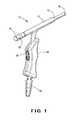
- FIG. 1is a perspective view of a preferred embodiment of the lighted suction device of the invention
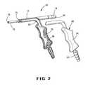
- FIG. 2is a perspective, exploded view of the device shown in FIG. 1 ;
- FIG. 3is a side, partially schematic view of the device shown in FIG. 1 ;
- FIG. 4is a top view of the device shown in FIG. 1 ;
- FIG. 5is a rear view of the device shown in FIG. 1 .
- the current inventionis a lighted suction device and method of removing an object from a body orifice such as the ear canal utilizing the lighted suction device to provide both illumination and visualization during the procedure.
- the illuminationis preferably provided by a white LED (light emitting diode) that transmits light into the ear canal using the suction device as a light pipe.
- the visualizationmay be enhanced by a magnifying lens that can be removably attached to the suction device.
- the lighted suction device assemblymay be attached to a standard vacuum unit as described below to provide suction for the procedure.
- the lighted suction device 10includes a light pipe member or portion 12 .
- the light pipe member 12is elongate, extending from a butt or proximal end 14 to a shoulder 15 to a tip 16 . It may be preferred to form the tip 16 of the lighted suction device 10 so as to be slightly flared, to allow it to more readily adhere to round foreign bodies.
- the proximal end 14 of the light pipe member 12is designed to connect to a light source 18 , preferably a bright white LED light source that provides the source of illumination.
- At least the light pipe member 12 of the lighted suction device 10is composed of a transparent material that has good transparency and haze that is sufficiently low to allow it to function as a light pipe.
- the transparent material of the light pipe member 12may be glass or a plastic material, preferably a polycarbonate, acrylic or co-polyester material.
- the lighted suction device 10further includes a suction channel or passage 20 that may be integral to the light pipe member 12 or may be a catheter-type member that is affixed in a permanent fashion to the light pipe member 12 .
- the suction channel 20is formed integrally with the light pipe member 12 , as best seen in FIG. 2 .
- the suction channel 20terminates at one end in an opening 22 at the tip 16 of the light pipe member 12 and at the other end or proximal end in a connector 24 for connection to a source of vacuum 26 .
- the lighted suction device 10preferably includes a handle 28 extending from the light pipe member 12 .
- a portion of the suction channel 20 and the connector 24are formed integrally with the handle 28 .
- the connector 28is preferably a standard hose connector, such as the hose barb shown, allowing the lighted suction device 10 to connect with the suction channel 20 in fluid communication with any standard suction system, including a wall-vacuum or vacuum pump.
- a small hole 30may preferably be located in the handle 28 of the lighted suction device 10 to allow finger-tip control of the vacuum by a user.
- the light pipe member 12including the suction tip 16 , and one half of the handle 28 and hose barb connector 24 are molded as a single piece, together forming a light pipe component assembly.
- the light pipe member 12is connected to a LED light source 18 (shown schematically in FIG. 3 ) via the bayonette configuration 32 at its rearward or proximal end 14 .
- Lighttravels from the light source 18 through the light pipe member 12 , exiting as the light pipe member 12 transitions at the shoulder 15 to the tip 16 where it exceeds the critical angle.
- the handle portion 28is formed from the assembly of the light pipe member 12 and the mating half 34 of the handle 28 .
- the interior of the handle 28defines a portion of the suction channel 20 , and preferably is provided with one or more baffles that form a debris trap for suctioned cerumen, objects or the like.
- FIG. 2shows a first baffle 36 and a second baffle 38 within that portion of the suction channel 20 within the handle 28 .
- the vacuum source 26connects to the lighted suction device 10 via the hose barb connector 24 formed by the assembly of the light pipe component assembly and the mating half 34 of the handle 28 .
- FIG. 2an exploded view of the device 10 , the interior geometry of the illustrated embodiment of the lighted suction device 10 is clearly visible.
- the single-piece light pipe component assembly of the lighted suction device 10also includes the baffles 36 and 38 forming the debris trap.
- the suction tip 16is shown as a closed channel at its distal end, transitioning into an open geometry that joins with the mating half 34 of the handle 28 and suction channel component of the device.
- the interior of the handle 28has one or more baffles that serve to form a debris trap that catches larger particles and keeps them from being drawn into the suction tubing.
- the vacuum source 26connects via suction tubing or the like to the hose barb connector 24 formed by the assembly of the light pipe component assembly and the mating half 34 of the handle 28 .
- FIG. 3shows a side view of the lighted suction device from 10 the perspective of the light pipe component assembly side, which as illustrated is molded as a single piece.
- the light pipe member 12is shown from its rearward or proximal end 14 , where it inserts into the LED light source 18 , to the shoulder 15 , where an abrupt transition to the suction tip 16 exceeds the critical angle for light transmission through the material, and thus allows light to escape (exit) at that point.
- the handle portion 28containing the debris trap formed in the suction channel 20 by the baffles 36 , 38 and the hose barb connector 24 , extends downward and away from the light pipe member 12 .
- FIG. 7shows the assembled lighted suction device 10 from the rear.
- the thumb hole 30 used to control the suctionis clearly visible.
- the two halves of the devicemate to form the handle portion 28 and hose barb connector 30 .
Landscapes
- Health & Medical Sciences (AREA)
- Life Sciences & Earth Sciences (AREA)
- Surgery (AREA)
- Heart & Thoracic Surgery (AREA)
- Engineering & Computer Science (AREA)
- Biomedical Technology (AREA)
- Animal Behavior & Ethology (AREA)
- Veterinary Medicine (AREA)
- Optics & Photonics (AREA)
- Public Health (AREA)
- Physics & Mathematics (AREA)
- General Health & Medical Sciences (AREA)
- Medical Informatics (AREA)
- Molecular Biology (AREA)
- Pathology (AREA)
- Biophysics (AREA)
- Nuclear Medicine, Radiotherapy & Molecular Imaging (AREA)
- Radiology & Medical Imaging (AREA)
- Vascular Medicine (AREA)
- Anesthesiology (AREA)
- Hematology (AREA)
- Microelectronics & Electronic Packaging (AREA)
- Endoscopes (AREA)
Abstract
Description
Claims (13)
Priority Applications (1)
| Application Number | Priority Date | Filing Date | Title |
|---|---|---|---|
| US13/677,393US9114202B1 (en) | 2011-11-15 | 2012-11-15 | Lighted suction device |
Applications Claiming Priority (2)
| Application Number | Priority Date | Filing Date | Title |
|---|---|---|---|
| US201161560023P | 2011-11-15 | 2011-11-15 | |
| US13/677,393US9114202B1 (en) | 2011-11-15 | 2012-11-15 | Lighted suction device |
Publications (1)
| Publication Number | Publication Date |
|---|---|
| US9114202B1true US9114202B1 (en) | 2015-08-25 |
Family
ID=53838287
Family Applications (1)
| Application Number | Title | Priority Date | Filing Date |
|---|---|---|---|
| US13/677,393Active2033-03-27US9114202B1 (en) | 2011-11-15 | 2012-11-15 | Lighted suction device |
Country Status (1)
| Country | Link |
|---|---|
| US (1) | US9114202B1 (en) |
Cited By (6)
| Publication number | Priority date | Publication date | Assignee | Title |
|---|---|---|---|---|
| US20160313499A1 (en)* | 2014-11-12 | 2016-10-27 | Invuity, Inc. | Thermally controlled illumination devices |
| US20170224886A1 (en)* | 2016-02-09 | 2017-08-10 | Daley Solutions, LLC | Apparatus and method for removing debris from an orifice |
| CN108904901A (en)* | 2018-07-20 | 2018-11-30 | 芜湖碧水谣医疗设备科技有限公司 | A kind of Respiratory Medicine sputum aspirator |
| US20220167957A1 (en)* | 2020-12-01 | 2022-06-02 | Nelson Jose Finol Gutierrez | Surgical Lingual Retractor Plus |
| US20230320809A1 (en)* | 2016-07-11 | 2023-10-12 | Obp Surgical Copporation | Illuminated suction device |
| US20250127981A1 (en)* | 2023-10-20 | 2025-04-24 | Coopersurgical, Inc. | Illuminated suction device |
Citations (18)
| Publication number | Priority date | Publication date | Assignee | Title |
|---|---|---|---|---|
| US3261356A (en)* | 1963-10-21 | 1966-07-19 | American Cystoscope Makers Inc | Suction and illumination device |
| US5897489A (en)* | 1997-05-27 | 1999-04-27 | Urbanowicz; Cynthia | Snap-on suction tube for laryngoscope |
| US6569089B1 (en)* | 1999-12-03 | 2003-05-27 | Roy Covington | Lighted intubating laryngoscope |
| US20040195975A1 (en)* | 2000-01-14 | 2004-10-07 | Gilbert Fregoso | Circuit for driving light-emitting diodes |
| US20050171408A1 (en)* | 1997-07-02 | 2005-08-04 | Parker Jeffery R. | Light delivery systems and applications thereof |
| US20060276693A1 (en)* | 2005-04-01 | 2006-12-07 | Pacey John A | Video rectractor |
| US20070060793A1 (en)* | 2005-08-30 | 2007-03-15 | Degould Michael D | Suction retraction instrument for surgery |
| US20070088203A1 (en)* | 2005-05-25 | 2007-04-19 | Liming Lau | Surgical assemblies and methods for visualizing and performing surgical procedures in reduced-access surgical sites |
| US20080146878A1 (en)* | 2006-12-14 | 2008-06-19 | Karen Naimoli Frost | Magnification attachment / accessory for laryngoscopes |
| US20090253967A1 (en)* | 2001-10-19 | 2009-10-08 | Visionscope Technologies, Llc | Portable imaging system employing a miniature endoscope |
| US20090312783A1 (en)* | 2008-06-12 | 2009-12-17 | Ncontact Surgical, Inc. | Dissecting cannula and methods of use thereof |
| US7641644B2 (en)* | 2004-04-21 | 2010-01-05 | Acclarent, Inc. | Devices, systems and methods for treating disorders of the ear, nose and throat |
| US20100249528A1 (en)* | 2006-06-13 | 2010-09-30 | Invuity, Inc. | Film Illumination System |
| US20110112376A1 (en)* | 2009-11-10 | 2011-05-12 | Invuity, Inc. | Illuminated Suction Apparatus |
| US20110313412A1 (en)* | 2009-02-23 | 2011-12-22 | Miramar Labs, Inc. | Tissue interface system and method |
| US20120179187A1 (en)* | 2011-01-07 | 2012-07-12 | Preceptis Medical, Inc. | Stabilization system and aspiration device with protected cutting edge |
| US20120277537A1 (en)* | 2004-01-29 | 2012-11-01 | Cannuflow, Inc. | Atraumatic Arthroscopic Instrument Sheath |
| US20130012783A1 (en)* | 2010-12-16 | 2013-01-10 | Invuity, Inc. | Illuminated suction apparatus |
- 2012
- 2012-11-15USUS13/677,393patent/US9114202B1/enactiveActive
Patent Citations (19)
| Publication number | Priority date | Publication date | Assignee | Title |
|---|---|---|---|---|
| US3261356A (en)* | 1963-10-21 | 1966-07-19 | American Cystoscope Makers Inc | Suction and illumination device |
| US5897489A (en)* | 1997-05-27 | 1999-04-27 | Urbanowicz; Cynthia | Snap-on suction tube for laryngoscope |
| US20050171408A1 (en)* | 1997-07-02 | 2005-08-04 | Parker Jeffery R. | Light delivery systems and applications thereof |
| US6569089B1 (en)* | 1999-12-03 | 2003-05-27 | Roy Covington | Lighted intubating laryngoscope |
| US20040195975A1 (en)* | 2000-01-14 | 2004-10-07 | Gilbert Fregoso | Circuit for driving light-emitting diodes |
| US20090253967A1 (en)* | 2001-10-19 | 2009-10-08 | Visionscope Technologies, Llc | Portable imaging system employing a miniature endoscope |
| US20120277537A1 (en)* | 2004-01-29 | 2012-11-01 | Cannuflow, Inc. | Atraumatic Arthroscopic Instrument Sheath |
| US7641644B2 (en)* | 2004-04-21 | 2010-01-05 | Acclarent, Inc. | Devices, systems and methods for treating disorders of the ear, nose and throat |
| US20060276693A1 (en)* | 2005-04-01 | 2006-12-07 | Pacey John A | Video rectractor |
| US20070088203A1 (en)* | 2005-05-25 | 2007-04-19 | Liming Lau | Surgical assemblies and methods for visualizing and performing surgical procedures in reduced-access surgical sites |
| US20070060793A1 (en)* | 2005-08-30 | 2007-03-15 | Degould Michael D | Suction retraction instrument for surgery |
| US20100249528A1 (en)* | 2006-06-13 | 2010-09-30 | Invuity, Inc. | Film Illumination System |
| US20080146878A1 (en)* | 2006-12-14 | 2008-06-19 | Karen Naimoli Frost | Magnification attachment / accessory for laryngoscopes |
| US20090312783A1 (en)* | 2008-06-12 | 2009-12-17 | Ncontact Surgical, Inc. | Dissecting cannula and methods of use thereof |
| US20110313412A1 (en)* | 2009-02-23 | 2011-12-22 | Miramar Labs, Inc. | Tissue interface system and method |
| US20110112376A1 (en)* | 2009-11-10 | 2011-05-12 | Invuity, Inc. | Illuminated Suction Apparatus |
| US20130012784A1 (en)* | 2009-11-10 | 2013-01-10 | Invuity, Inc, | Illuminated suction apparatus |
| US20130012783A1 (en)* | 2010-12-16 | 2013-01-10 | Invuity, Inc. | Illuminated suction apparatus |
| US20120179187A1 (en)* | 2011-01-07 | 2012-07-12 | Preceptis Medical, Inc. | Stabilization system and aspiration device with protected cutting edge |
Cited By (9)
| Publication number | Priority date | Publication date | Assignee | Title |
|---|---|---|---|---|
| US20160313499A1 (en)* | 2014-11-12 | 2016-10-27 | Invuity, Inc. | Thermally controlled illumination devices |
| US10969536B2 (en) | 2014-11-12 | 2021-04-06 | Invuity, Inc. | Thermally controlled illumination devices |
| US12376736B2 (en) | 2014-11-12 | 2025-08-05 | Invuity, Inc. | Thermally controlled illumination devices |
| US20170224886A1 (en)* | 2016-02-09 | 2017-08-10 | Daley Solutions, LLC | Apparatus and method for removing debris from an orifice |
| US10471187B2 (en)* | 2016-02-09 | 2019-11-12 | Daley Solutions, LLC | Apparatus and method for removing debris from an orifice |
| US20230320809A1 (en)* | 2016-07-11 | 2023-10-12 | Obp Surgical Copporation | Illuminated suction device |
| CN108904901A (en)* | 2018-07-20 | 2018-11-30 | 芜湖碧水谣医疗设备科技有限公司 | A kind of Respiratory Medicine sputum aspirator |
| US20220167957A1 (en)* | 2020-12-01 | 2022-06-02 | Nelson Jose Finol Gutierrez | Surgical Lingual Retractor Plus |
| US20250127981A1 (en)* | 2023-10-20 | 2025-04-24 | Coopersurgical, Inc. | Illuminated suction device |
Similar Documents
| Publication | Publication Date | Title |
|---|---|---|
| US9114202B1 (en) | Lighted suction device | |
| US20130023914A1 (en) | System for accessing body orifice and method | |
| US10675390B2 (en) | Combined coaxial and bimanual irrigation/aspiration apparatus | |
| US8840546B2 (en) | System for accessing a body orifice | |
| CN103237530B (en) | Combined coaxial and two-handed irrigation/suction unit | |
| US20080058832A1 (en) | Tympanic membrane drain tube | |
| JP5124721B2 (en) | Lacrimal tract treatment device | |
| US8545462B2 (en) | Patch for irrigation/aspiration tip | |
| JP2016523610A (en) | Deformation type cleaning / suction device | |
| JP5360650B2 (en) | Lacrimal tract treatment device | |
| CN207562152U (en) | Medical modified form surgery aspirator | |
| US20130150675A1 (en) | Transparent Speculum Apparatus and System | |
| CN209678842U (en) | Eustachian tube aspirator | |
| US12402974B1 (en) | Lighted surgical instrument | |
| US20250186680A1 (en) | Device for ear and related methods | |
| CN221751103U (en) | Puncture cannula for microscopic ophthalmic surgery | |
| US12370090B2 (en) | Narrow-orifice foreign body extraction device | |
| CN212214020U (en) | Ear canal aspirator for otolaryngological department | |
| CN111803729B (en) | Surgical suction device | |
| CN109350359A (en) | Eustachian tube aspirator | |
| CN209285920U (en) | A kind of micro- suction cutting stripper of ear | |
| CN208481421U (en) | A kind of visual water pocket elevator of negative pressure | |
| CN2403394Y (en) | Ceratuba earwax extractor | |
| CN203341912U (en) | Ear bent tweezers with suction tubes | |
| KR101786184B1 (en) | The internal structure of visibility is widened endoscope |
Legal Events
| Date | Code | Title | Description |
|---|---|---|---|
| AS | Assignment | Owner name:BIONIX DEVELOPMENT CORPORATION, OHIO Free format text:ASSIGNMENT OF ASSIGNORS INTEREST;ASSIGNOR:HUTTNER, JAMES J.;REEL/FRAME:029301/0209 Effective date:20121115 | |
| STCF | Information on status: patent grant | Free format text:PATENTED CASE | |
| MAFP | Maintenance fee payment | Free format text:PAYMENT OF MAINTENANCE FEE, 4TH YR, SMALL ENTITY (ORIGINAL EVENT CODE: M2551); ENTITY STATUS OF PATENT OWNER: SMALL ENTITY Year of fee payment:4 | |
| AS | Assignment | Owner name:BIONIX, LLC, OHIO Free format text:ASSIGNMENT OF ASSIGNORS INTEREST;ASSIGNORS:BIONIX DEVELOPMENT CORPORATION;BIONIX HEALTH AT HOME LLC;BIONIX MEDICAL TECHNOLOGIES, LLC;AND OTHERS;REEL/FRAME:054801/0832 Effective date:20201230 | |
| MAFP | Maintenance fee payment | Free format text:PAYMENT OF MAINTENANCE FEE, 8TH YR, SMALL ENTITY (ORIGINAL EVENT CODE: M2552); ENTITY STATUS OF PATENT OWNER: SMALL ENTITY Year of fee payment:8 |