US9114055B2 - Deep vein thrombosis (“DVT”) and thermal/compression therapy systems, apparatuses and methods - Google Patents
Deep vein thrombosis (“DVT”) and thermal/compression therapy systems, apparatuses and methodsDownload PDFInfo
- Publication number
- US9114055B2 US9114055B2US13/419,022US201213419022AUS9114055B2US 9114055 B2US9114055 B2US 9114055B2US 201213419022 AUS201213419022 AUS 201213419022AUS 9114055 B2US9114055 B2US 9114055B2
- Authority
- US
- United States
- Prior art keywords
- chamber
- cuff
- pressure
- line
- therapy system
- Prior art date
- Legal status (The legal status is an assumption and is not a legal conclusion. Google has not performed a legal analysis and makes no representation as to the accuracy of the status listed.)
- Active, expires
Links
- 238000002560therapeutic procedureMethods0.000titleclaimsabstractdescription94
- 206010051055Deep vein thrombosisDiseases0.000titledescription88
- 230000006835compressionEffects0.000titledescription87
- 238000007906compressionMethods0.000titledescription87
- 238000000034methodMethods0.000titledescription19
- 206010047249Venous thrombosisDiseases0.000titledescription3
- 230000037361pathwayEffects0.000claimsabstractdescription28
- 238000004891communicationMethods0.000claimsabstractdescription11
- 239000012530fluidSubstances0.000claimsabstractdescription11
- 238000007789sealingMethods0.000claimsdescription5
- WYTGDNHDOZPMIW-RCBQFDQVSA-NalstonineNatural productsC1=CC2=C3C=CC=CC3=NC2=C2N1C[C@H]1[C@H](C)OC=C(C(=O)OC)[C@H]1C2WYTGDNHDOZPMIW-RCBQFDQVSA-N0.000claimsdescription3
- 239000002904solventSubstances0.000claimsdescription3
- 230000001934delayEffects0.000abstractdescription4
- 210000002414legAnatomy0.000description15
- XLYOFNOQVPJJNP-UHFFFAOYSA-NwaterSubstancesOXLYOFNOQVPJJNP-UHFFFAOYSA-N0.000description14
- 239000000463materialSubstances0.000description11
- 210000003414extremityAnatomy0.000description9
- 239000004433Thermoplastic polyurethaneSubstances0.000description8
- 229920002803thermoplastic polyurethanePolymers0.000description8
- 230000008901benefitEffects0.000description6
- 238000003466weldingMethods0.000description6
- 210000003462veinAnatomy0.000description4
- 125000000391vinyl groupChemical group[H]C([*])=C([H])[H]0.000description4
- 229920002554vinyl polymerPolymers0.000description4
- 239000008280bloodSubstances0.000description3
- 210000004369bloodAnatomy0.000description3
- 238000005336crackingMethods0.000description3
- 239000007788liquidSubstances0.000description3
- 210000003141lower extremityAnatomy0.000description3
- 238000012986modificationMethods0.000description3
- 230000004048modificationEffects0.000description3
- 230000008569processEffects0.000description3
- 238000001356surgical procedureMethods0.000description3
- 230000017531blood circulationEffects0.000description2
- 230000008859changeEffects0.000description2
- 238000001816coolingMethods0.000description2
- 201000010099diseaseDiseases0.000description2
- 208000037265diseases, disorders, signs and symptomsDiseases0.000description2
- 210000002683footAnatomy0.000description2
- 230000006870functionEffects0.000description2
- 210000003127kneeAnatomy0.000description2
- 230000004044responseEffects0.000description2
- 238000012163sequencing techniqueMethods0.000description2
- 230000008961swellingEffects0.000description2
- 200000000007Arterial diseaseDiseases0.000description1
- 206010007559Cardiac failure congestiveDiseases0.000description1
- 206010053567CoagulopathiesDiseases0.000description1
- 206010019280Heart failuresDiseases0.000description1
- 208000007536ThrombosisDiseases0.000description1
- 230000009471actionEffects0.000description1
- 210000004712air sacAnatomy0.000description1
- 210000003423ankleAnatomy0.000description1
- 238000003287bathingMethods0.000description1
- 230000009286beneficial effectEffects0.000description1
- 210000004556brainAnatomy0.000description1
- 230000009172burstingEffects0.000description1
- 244000309466calfSpecies0.000description1
- 230000004087circulationEffects0.000description1
- 230000035602clottingEffects0.000description1
- 238000002648combination therapyMethods0.000description1
- 238000004590computer programMethods0.000description1
- 208000018999crinkleDiseases0.000description1
- 230000007423decreaseEffects0.000description1
- 230000003247decreasing effectEffects0.000description1
- 230000003467diminishing effectEffects0.000description1
- 230000003203everyday effectEffects0.000description1
- 230000035876healingEffects0.000description1
- 210000004072lungAnatomy0.000description1
- 230000013011matingEffects0.000description1
- 239000002184metalSubstances0.000description1
- 210000003205muscleAnatomy0.000description1
- 230000000399orthopedic effectEffects0.000description1
- 229920003023plasticPolymers0.000description1
- 239000004033plasticSubstances0.000description1
- 239000002985plastic filmSubstances0.000description1
- 238000005086pumpingMethods0.000description1
- 208000037974severe injuryDiseases0.000description1
- 230000009528severe injuryEffects0.000description1
- 206010040872skin infectionDiseases0.000description1
- 208000024891symptomDiseases0.000description1
- 230000001360synchronised effectEffects0.000description1
- 238000011144upstream manufacturingMethods0.000description1
Images


Classifications
- A—HUMAN NECESSITIES
- A61—MEDICAL OR VETERINARY SCIENCE; HYGIENE
- A61H—PHYSICAL THERAPY APPARATUS, e.g. DEVICES FOR LOCATING OR STIMULATING REFLEX POINTS IN THE BODY; ARTIFICIAL RESPIRATION; MASSAGE; BATHING DEVICES FOR SPECIAL THERAPEUTIC OR HYGIENIC PURPOSES OR SPECIFIC PARTS OF THE BODY
- A61H9/00—Pneumatic or hydraulic massage
- A61H9/005—Pneumatic massage
- A61H9/0078—Pneumatic massage with intermittent or alternately inflated bladders or cuffs
- A61H9/0092—Cuffs therefor
- A—HUMAN NECESSITIES
- A61—MEDICAL OR VETERINARY SCIENCE; HYGIENE
- A61H—PHYSICAL THERAPY APPARATUS, e.g. DEVICES FOR LOCATING OR STIMULATING REFLEX POINTS IN THE BODY; ARTIFICIAL RESPIRATION; MASSAGE; BATHING DEVICES FOR SPECIAL THERAPEUTIC OR HYGIENIC PURPOSES OR SPECIFIC PARTS OF THE BODY
- A61H9/00—Pneumatic or hydraulic massage
- A61H9/005—Pneumatic massage
- A61H9/0078—Pneumatic massage with intermittent or alternately inflated bladders or cuffs
- A—HUMAN NECESSITIES
- A61—MEDICAL OR VETERINARY SCIENCE; HYGIENE
- A61H—PHYSICAL THERAPY APPARATUS, e.g. DEVICES FOR LOCATING OR STIMULATING REFLEX POINTS IN THE BODY; ARTIFICIAL RESPIRATION; MASSAGE; BATHING DEVICES FOR SPECIAL THERAPEUTIC OR HYGIENIC PURPOSES OR SPECIFIC PARTS OF THE BODY
- A61H2201/00—Characteristics of apparatus not provided for in the preceding codes
- A61H2201/02—Characteristics of apparatus not provided for in the preceding codes heated or cooled
- A61H2201/0214—Characteristics of apparatus not provided for in the preceding codes heated or cooled cooled
- A—HUMAN NECESSITIES
- A61—MEDICAL OR VETERINARY SCIENCE; HYGIENE
- A61H—PHYSICAL THERAPY APPARATUS, e.g. DEVICES FOR LOCATING OR STIMULATING REFLEX POINTS IN THE BODY; ARTIFICIAL RESPIRATION; MASSAGE; BATHING DEVICES FOR SPECIAL THERAPEUTIC OR HYGIENIC PURPOSES OR SPECIFIC PARTS OF THE BODY
- A61H2201/00—Characteristics of apparatus not provided for in the preceding codes
- A61H2201/02—Characteristics of apparatus not provided for in the preceding codes heated or cooled
- A61H2201/0221—Mechanism for heating or cooling
- A61H2201/0242—Mechanism for heating or cooling by a fluid circulating in the apparatus
- A—HUMAN NECESSITIES
- A61—MEDICAL OR VETERINARY SCIENCE; HYGIENE
- A61H—PHYSICAL THERAPY APPARATUS, e.g. DEVICES FOR LOCATING OR STIMULATING REFLEX POINTS IN THE BODY; ARTIFICIAL RESPIRATION; MASSAGE; BATHING DEVICES FOR SPECIAL THERAPEUTIC OR HYGIENIC PURPOSES OR SPECIFIC PARTS OF THE BODY
- A61H2201/00—Characteristics of apparatus not provided for in the preceding codes
- A61H2201/50—Control means thereof
- A61H2201/5002—Means for controlling a set of similar massage devices acting in sequence at different locations on a patient
- A—HUMAN NECESSITIES
- A61—MEDICAL OR VETERINARY SCIENCE; HYGIENE
- A61H—PHYSICAL THERAPY APPARATUS, e.g. DEVICES FOR LOCATING OR STIMULATING REFLEX POINTS IN THE BODY; ARTIFICIAL RESPIRATION; MASSAGE; BATHING DEVICES FOR SPECIAL THERAPEUTIC OR HYGIENIC PURPOSES OR SPECIFIC PARTS OF THE BODY
- A61H2201/00—Characteristics of apparatus not provided for in the preceding codes
- A61H2201/50—Control means thereof
- A61H2201/5058—Sensors or detectors
- A61H2201/5071—Pressure sensors
- A—HUMAN NECESSITIES
- A61—MEDICAL OR VETERINARY SCIENCE; HYGIENE
- A61H—PHYSICAL THERAPY APPARATUS, e.g. DEVICES FOR LOCATING OR STIMULATING REFLEX POINTS IN THE BODY; ARTIFICIAL RESPIRATION; MASSAGE; BATHING DEVICES FOR SPECIAL THERAPEUTIC OR HYGIENIC PURPOSES OR SPECIFIC PARTS OF THE BODY
- A61H2209/00—Devices for avoiding blood stagnation, e.g. Deep Vein Thrombosis [DVT] devices
Definitions
- the present disclosurerelates generally to orthopedics and in particular to deep vein thrombosis (“DVT”) and thermal/compression therapy systems, apparatuses and methods.
- DVDdeep vein thrombosis
- DVTis a condition that occurs when a blood clot forms in a patient's vein deep in the body, usually in the patient's legs or the feet.
- the clotcan block proper blood flow and may lead to severe injury or death if the clot breaks off and travels through the bloodstream to other areas of the body, such as the brain or lungs.
- Doctorssometimes recommend compression therapy for people with or prone to developing DVT.
- Compression therapyworks by exerting varying degrees of pressure on the legs, especially the lower legs, which helps the blood to flow back towards the patient's heart.
- the pressurehelps blood in the surface level veins travel to the deeper veins and back to the heart rather than collecting and clotting in the lower extremities.
- Compression therapyalso helps to reduce pain and swelling associated with DVT.
- compression stockingsOne way to exert pressure on the patient's legs is via compression stockings. For a minimal amount of pressure, women's type pantyhose may be sufficient. If moderate support is required, over-the-counter compression stockings from a pharmacy or medical supply store may be used. There are also prescription strength compression stockings, which need to be fitted to the patient.
- the patientshould wear the compression stockings every day, as long as the patient is experiencing DVT-related symptoms or is at risk for developing DVT.
- the stockingsshould be worn throughout the day, even while exercising. The patient can remove the stockings for bathing and at night when while sleeping.
- Compression garmentsmay worsen the disease in diabetics, smokers and those who have poor circulation in the legs if compression garments are worn.
- the compression garmentscan also cause skin infection.
- pneumatic compressionmay be applied.
- hospital patientsthat are bedridden or have recently undergone surgery are often treated with pneumatic compression devices to help prevent DVT.
- Known pneumatic compression devicesinclude sleeves or cuffs that are applied around a patient's lower extremity and fastened removably by hook and pile straps for example.
- the cuffsare connected to a pump enabling the cuff to be inflated and deflated to aid in blood flow from the lower extremity back to the patient's heart.
- compression garmentscan be uncomfortable. This can be especially true in warmer climates. Compression garments are also not available to every DVT patient. And pneumatic compression devices have for the most part been used in hospitals. A need accordingly exists for a relatively low cost pneumatic compression device that can be used in the patient's home, in addition to or in the place of compression garments.
- the present disclosureprovides a combination pressure therapy system, method and apparatus, for example, to treat deep vein thrombosis (“DVT”) and other diseases, ailments and pain, such as sore muscles or joints.
- the systemin one embodiment is microprocessor-based and includes electronics having at least one processor, memory device, power supply (e.g., to convert alternating current (“AC”) voltage to direct current (“DC”) voltage), and input/output switching.
- Input/output switchingreceives commands from the processor, according to a computer program stored on the memory device.
- the processorreceives signals (e.g., via the input/output switching) from various sensors, such as pressure sensors.
- the processorin response to the signals (or to an input from the user) commands the input/output switching to control a pump and valves to nm a selected therapy.
- the systemincludes a user interface, which includes on/off input devices or switches that allow the user to turn on and off one or more therapy of the system.
- the user interfacemay also have one or more display or readout, such as a temperature display for a thermal/compression therapy and/or a pressure readout for a DVT therapy.
- the systemin one embodiment provides both a DVT therapy and a thermal/compression therapy.
- the user interfacemay include a master on/off switch that turns the system on and off and a second switch that controls just the thermal/compression therapy. Thus only the master switch needs to be turned on to run the DVT therapy in one embodiment. Both switches need to be turned on to runm only the thermal/compression therapy or to run both therapies.
- the DVT therapycan include two pneumatic lines, each leading to a DVT cuff (e.g., left and right) in one embodiment.
- the pneumatic linesin an embodiment each operate with a control valve and a bleed valve.
- the valvescan each be normally closed valves, such that the control valves are each opened to pressurize the lines (and cuffs) upon energization, while the bleed valves are each opened to depressurize the lines (and cuffs) upon energization.
- the pneumatic lineseach include a pressure sensor or transducer, which sends a pressure signal back to the control electronics. The pressure signal is used as feedback to maintain the pressure in the lines at a preset, desired pressure.
- the bleed valvesin one embodiment are adjustable to maintain a residual pressure in the pneumatic lines upon depressurization. Alternatively, the valves are depressurized to atmospheric pressure.
- the DVT cuffscan be pressurized in many different ways in which the duration of the pressurization, the rate at which the maximum pressure is reached and the maximum pressure itself can be varied.
- the left and right cuffsare pressurized at different times so that the pump does not have to be sized to inflate both cuffs simultaneously.
- the cuffscould alternatively be pressurized at the same time or have overlapping pressurizations.
- the first cuffis inflated for six seconds from time zero and then deflated to a residual pressure.
- the second cuffis then inflated for six seconds beginning from time six seconds from zero to time twelve seconds from zero and then deflated to a residual pressure.
- both cuffsremain at the residual pressure until time sixty seconds from zero at which time the sequence just described is repeated. While the below example shows two cuffs, the system could alternatively provide and inflate one cuff or more than two cuffs, e.g., in a non-overlapping manner.
- the system in one embodimentalso provides a thermal/compression therapy wrap, which includes an inner chamber that receives a flow of water, e.g., chilled water, pumped from an ice bath, and an outer chamber that receives pressurized air.
- the pressurization of the thermal/compression therapy wrapis controlled by the same processor that controls DVT cuff inflation, but is completely independent of DVT inflation and vice versa.
- the compression wrapcan be pressurized in many different ways in which the duration of the pressurization, the rate at which the maximum pressure is reached, and the maximum pressure itself can be varied. In one embodiment illustrated below, pressure in the wrap is ramped up slowly, e.g. over forty-five seconds, in a linear manner, and then ramped down slowly, e.g. over forty-five seconds, in a linear manner. Pressure feedback is used with the electronics to control the desired waveform.
- the thermal/compression pressure waveformcan be run (i) by itself, (ii) while the DYT pressure waveforms are being run and in sync with or as part of an overall sequence or cycle with the DVT waveforms, or (iii) while the DVT pressure waveforms are being run and out of sync with or completely independent of the DVT waveforms.
- the wrapcan be inflated at the same time or at different times than the DVT cuffs are inflated.
- the thermal/compression therapy wrapcan therefore be worn by itself or in combination with the DVT cuffs.
- the thermal/compression therapy wrapcan be worn anywhere thermal/compression therapy is needed. For example, if a patient has had knee surgery, the thermal/compression therapy wrap can be worn around the healing knee to reduce swelling, while the DVT cuffs are worn close to the patient's ankles to help keep blood circulating within the patient over prolonged periods of rest and non-movement. This application can be performed immediately after surgery at the hospital and/or later when the patient returns home.
- the pumppressurizes a reservoir that is used in turn to pressurize the DVT cuffs and the thermal/compression therapy wrap.
- one or more pump(s)are used to directly pressurize the DVT cuffs and the thermal/compression therapy wrap.
- pressurized airis used in each pneumatic line with a control valve, bleed valve and pressure sensor in one embodiment to achieve the pressure profile stored in and executed by the electronics.
- each DVT cuffis attached to a single pneumatic line, which is advantageous for cost, weight and simplicity reasons.
- Each cuffincludes two inflatable chambers that are fluidly separated from each other.
- Each DVT pneumatic lineextends from the housing of the system and splits at the DVT cuff into a first line segment and a second line segment.
- the first line segmentextends to a distal air chamber (distal on leg relative to the heart when the cuff is properly donned), which is pressurized first when the pneumatic line is pressurized.
- the second line segmentextends to a proximal air chamber (proximal on leg relative to the heart when the cuff is properly donned), which is pressurized second when the pneumatic line is pressurized.
- the delay in pressurizing the second or proximal air chamberis caused by a flow restricting structure that is placed in the second line segment or in a passageway in the cuff leading from the second line segment to the second air chamber.
- the first and second line segmentscan split at a “Y” connector.
- the “Y” connectorcan be outside the cuff, inside the cuff or pathway outside and pathway inside the cuff.
- the flow restricting structurecan be a narrowed and/or torturous passageway formed or placed in a second line segment portion of the “Y” connector.
- the flow restricting structurecan be a pneumatically operated valve check valve formed or placed in a second line segment portion of the “Y” connector.
- the flow restricting structureis further alternatively a torturous and/or narrowed passageway in the cuff leading to the proximal chamber.
- the cuffcan be sealed together from two plastic sheets to form the chambers. The same process can form baffles that extend part way across the cuff passageway and alternate, forcing air to move in a serpentine manner through a narrowed cross-section.
- the flow restricting structurecan be any combination of the structures just described.
- FIG. 1is a schematic view of one embodiment of a pneumatic circuit and system control of the present disclosure.
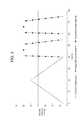
- FIG. 2Ais an example pressure waveform provided by the electronics, pneumatic circuit and DVT cuffs of the present disclosure.
- FIG. 2Bis an example pressure waveform provided by the electronics, pneumatic circuit and thermal/compression therapy wrap of the present disclosure.
- FIG. 3is an example pressure waveform provided by the electronics, pneumatic circuit, DVT cuffs and thermal/compression therapy wrap of the present disclosure.
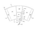
- FIG. 4is a plan view of one embodiment of a single line DVT cuff having a flow restricting structure leading to a proximal chamber of the cuff.
- FIG. 5is a plan view of a second embodiment of a single line DVT cuff having a flow restricting structure leading to a proximal chamber of the cuff.
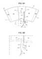
- FIG. 6Ais a plan view of a third embodiment of a single line DVT cuff having a flow restricting structure leading to a proximal chamber of the cuff.
- FIG. 6Bis a plan view of an enlarged portion of FIG. 6A , showing a pair of check valves in more detail.
- FIG. 7Ais a plan view of a forth alternative embodiment for a single line DVT cuff having a flow restricting structure leading to a proximal chamber of the cuff.
- FIG. 7Bis a plan view of a forth alternative embodiment for a single line DVT cuff having a flow restricting structure leading to a proximal chamber of the cuff.
- FIG. 8is a plan view of a sixth alternative embodiment for a single line DVT cuff having a flow restricting structure leading to a proximal chamber of the cuff.
- FIG. 9is a plan view of a seventh alternative embodiment for a single line DVT cuff having a flow restricting structure leading to a proximal chamber of the cuff.
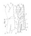
- FIG. 10is a top perspective view of one embodiment of a thermal/compression therapy wrap of the present disclosure having an outer air compression chamber made of an outer sheet that is larger than the inner sheets to allow the wrap to be more easily wrapped and inflated about a user's limb.
- System 10may employ any of several different pneumatic circuit alternatives.
- system 10may include: (i) a single pump driving multiple DVT cuff chambers and the thermal/compression therapy wrap without a reservoir; (ii) a single pump driving multiple DVT cuff chambers and the thermal/compression therapy wrap with a reservoir (shown schematically below); (iii) a first pump driving multiple DVT cuff chambers and a second pump driving the thermal/compression therapy wrap; and (iv) a pump dedicated to each DVT cuff chamber and a pump dedicated to the thermal/compression therapy wrap.
- System 10may alternatively include only a single DVT cuff, a single DVT cuff and thermal/compression therapy wrap or more than two DVT cuffs with or without a wrap driven via any one of (i) to (
- System 10includes an air pump 12 , for example, an Oken Sieko air pump, part number P54E01R.
- Pump 12is powered via electronics 50 , which can output alternating current (“AC”, e.g., 110/120 or 230/240 VAC) or direct current (“DC”, e.g., 24 VDC) to pump 12 and/or to the valves as described below.
- Electronics 50can include one or more processor 52 and memory 54 .
- Electronics 50may also include a power supply 56 , e.g., for converting AC line voltage 60 to DC voltage for powering pump 12 and the associated valves and/or pressure sensors.
- Electronics 50also include input/output switching 58 that receives commands from processor 52 and switches electrical contacts to either allow or disallow power to be delivered to the pumps, valves and pressure sensors.
- Air reservoir 20in the illustrated embodiment, can be a plastic or metal container sized and arranged to hold the maximum pressure that can be supplied via pneumatic line 22 d by pump 12 , plus an engineering factor of safety, e.g., 1.5 to 2.0 times the maximum pump output.
- Air reservoir 20holds pressurized air supplied to pneumatic lines 22 a , 22 b and 22 c , which in turn feeds pressurized air to left DVT cuff 100 a , right DVT cuff 100 b and thermal/compression therapy wrap 200 , respectively.
- Pneumatic lines 22 a , 22 b and 22 care controllably pressurized by control valves 14 , 16 and 18 , respectively, which (i) open to allow the pneumatic lines 22 a , 22 b or 22 c to become pressurized and (ii) close to prevent further pressurization of the line.
- control valves 14 , 16 and 18respectively, which (i) open to allow the pneumatic lines 22 a , 22 b or 22 c to become pressurized and (ii) close to prevent further pressurization of the line.
- pneumatic lines 22 a , 22 b , 22 care pressurized
- left cuff 100 a , right cuff 100 b and thermal/compression wrap 200are likewise respectively pressurized (e.g., according to staggered pressure chamber structures discussed below).
- Pneumatic lines 22 a , 22 b and 22 care each fluidly connected to a respective bleed valve 24 , 26 and 28 .
- Control valves and bleed valvesmay be, for example, valves provided by Koganei, part number GA010HE1.
- Bleed valves 24 , 26 and 28enable pneumatic lines 22 a , 22 b and 22 c and respective cuffs 100 a , 100 b and 200 to be depressurized. Depressurization of the lines and cuffs can be to atmospheric pressure. Alternatively, depressurization is to a modulated residual pressure, e.g., at slightly above zero gauge pressure.
- control valves 14 , 16 and 18 closedif bleed valves 24 , 26 and 28 are opened, pressure in the respective lines and cuff, or wrap, is bled to zero gauge pressure or a slightly higher residual pressure.
- Pneumatic lines 22 e , 22 f and 22 gextend off of pneumatic lines 22 a , 22 b and 22 c , respectively, and feed respective pressure sensors 34 , 36 and 38 .
- Pressure sensors 34 , 36 and 38send pressure signals back to electronics 50 , enabling (i) feedback to electronics 50 so that respective cuffs 100 a , 100 b and wrap 200 can be initially inflated to a desired pressure, and (ii) feedback to electronics 50 so that pressure in the cuffs and wrap can be maintained by opening control valves 14 , 16 or 18 to add pressure if needed or opening bleed valves 24 , 26 and 28 to relieve pressure if needed.
- Processing 52 and memory 54are programmed to receive the pressure signals, decide what action if any is needed, and operate input/output switches 56 to control the appropriate valve. As discussed in more detail below, electronics 50 and pump 12 operate to replenish reservoir 20 as needed so that the pressurization of cuffs 100 a and 100 b and wrap 200 can be performed repeatedly, as long as it is desired.
- Power lines (AC or DC) 32 a , 32 b , 32 c , 32 d , 32 e , 32 f and 32 g nfrom input/out switches 56 respectively to control valve 14 , control valve 16 , control valve 18 , pump 12 , bleed valve 24 , bleed valve 26 and bleed valve 28 .
- Signal lines 32 h , 32 i and 32 j(e.g., 0 to 5VDC or 4 to 20 mA) run from pressure sensors 34 , 36 or 38 , respectively, to input device 56 , which can include an A/D converter and other electronics needed to convert the pressure signal into digitized data used by processor 52 to make any necessary control response.
- control valves 14 , 16 and 18are normally closed valves as are bleed valves 24 , 26 and 28 . That is, upon loss of power, the valves will fail closed.
- any one or more of valves 14 , 16 , 18 , 24 , 26 and 28are normally open valves that close when energized. In such case, electronics 50 sends power to a valve when it is desired to keep the valve closed. Upon a power loss, pump 12 stops the pumping of air regardless of whether the control and bleed valves are normally open or normally closed.
- Bleed valves 24 , 26 and 28enable left cuff 100 a , right cuff 100 b and compression wrap 200 lines 22 a , 22 b and 22 c to vent to atmosphere, that is, relieve pressure in the lines.
- Bleed valves 24 , 26 and 28can be adjustably modulated to leave a residual pressure in their respective lines 22 a , 22 b and 22 c . It is contemplated in one embodiment to set bleed valves 24 , 26 , and 28 to leave about 10% of the maximum pressure (e.g., from 1.0 psig down to 0.1 psig) when the lines are depressurized.
- Valves 14 , 16 , 24 and 26control the DVT therapy, while valves 18 and 28 control the thermal/compression therapy.
- a single air pump 12supplies a reservoir, which will have a maximum pressure output for example of about eight psig.
- Reservoir 20will supply each of left cuff 100 a , right cuff 100 b and compression wrap 200 to achieve the desired pressure waveform rise times discussed below.
- Reservoir 20also dampens the pulsatility of the output of air pump 12 and thereby smoothes the pressure changes in the below—discussed pressure waveforms. Further, reservoir 20 lessens the frequency that air pump 50 has to be started and stopped, thereby extending the life of the air pump 12 .
- Air pump 12fills reservoir 20 as required, periodically over any of the pressure cycles discussed herein.
- Reservoir 20can have a pressure sensor (not illustrated) that feeds back a pressure signal to the electronics 50 , which uses the signal to control pump 12 to maintain pressure within the reservoir.
- the electronics 50may operate with a high pressure switch (not illustrated) to detect a maximum preset pressure for reservoir 20 and shut the air pump 12 off for a preset period or until a second, low pressure switch signals to turn pump 12 back on to regulate pressure in the reservoir 20 .
- software employed by processing 52 and memory 54 of electronics 50may anticipate the pressure of the reservoir 20 via knowledge of the operational pressure cycle and shut the air pump 50 off in an open loop fashion to control the pressure of reservoir 20 .
- air pump 12maintains the reservoir 20 in one embodiment at about two to about eight psig.
- the relatively low reservoir pressureallows left cuff 100 a , right cuff 100 b and compression wrap 200 lines 22 a , 22 b and 22 c to operate respectively without relief valve(s).
- a relief valvethat opens if the pressure in a respective one or more lines 22 a , 22 b and 22 c increases too much could be added if desired to any one or all of those lines. In such a case, a higher pressure in reservoir 20 can be maintained.
- Left cuff 100 a and right cuff 100 bare two separate cuffs (e.g., one for the patient's left leg and one for the patient's right leg), each having, e.g., two chambers, a distal chamber (pressurized first) and a proximal chamber (pressurized shortly afterward).
- each of the left and right cuffs 100 a and 100 bis a single line cuff and is operated as discussed next.
- air pump 12is energized at time T- 0 .
- control valve 14With bleed valve 26 closed (de-energized), control valve 14 is opened (energized) immediately after time T- 0 , at time T- 1 , and stays open until pressure sensor 34 reads about 0.8 psig, at which time control valve 14 is closed (de-energized).
- Control valve 14is then toggled on and off, using pressure feedback from pressure sensor 34 , so that the 0.8 psig pressure is maintained in the left cuff line 22 a and the left cuff 100 a for a specified duration, e.g., six seconds, the end of which corresponds to a time T- 2 .
- Control valve 14is then closed (de-energized) for the remainder of the cycle, while bleed valve 24 is opened (energized) for the remainder of the cycle time, e.g., until sixty seconds after time T- 0 , to relieve pressure in the left cuff line 100 a to a non-zero pressure (e.g., 0.1 psig) set by modulating bleed valve 24 .
- a non-zero pressuree.g., 0.1 psig
- the opening of bleed valve 24relieves pressure in the left cuff line 22 a and left cuff 100 a to about 0.1 psig during the remainder of time from T- 2 until sixty seconds after time T- 0 .
- a relief valve(not illustrated), if provided in left cuff line 22 a , would be set at some pressure above one psig.
- control valve 16is opened (energized) at time T- 2 , allowing right cuff line 22 b and the right cuff 100 b to become pressurized at the time when the left cuff line 22 a and the left cuff 100 a are vented to their residual pressure as just described.
- Control valve 16is then toggled on and off, using pressure feedback from pressure sensor 36 , so that about 0.8 psig pressure is maintained in the right cuff line 22 b and the right cuff 100 b for a specified period, e.g., six seconds, the end of which corresponds to time T- 3 .
- Control Valve 16is then closed (de-energized), while bleed valve 26 is opened (energized) for the remainder of the time until time T- 2 occurs in the next cycle, the next cycle beginning sixty seconds after time T- 0 .
- the opening of bleed valve 26relieves pressure in the right cuff line 22 b and the right cuff 100 b , again to about 0.1 psig, during the remainder of time until control valve 26 is next opened (energized) and bleed valve 26 is closed (de-energized).
- a relief valve(not illustrated), if provided in right cuff line 22 b , would again be set at some pressure above one psig.
- the DVT sequence just describedis illustrated graphically in FIG. 2A . Over a minute cycle, the sequence proceeds, e.g.: (i) left cuff 100 a pressurized, right cuff 100 b maintained at residual pressure (zero seconds to six seconds), (ii) left cuff 100 a maintained at residual pressure, right cuff 100 b pressurized (six seconds to twelve seconds), and then (iii) left cuff 100 a and right cuff 100 b maintained at residual pressure (twelve seconds to sixty seconds). The sequence just described is then repeated as many times as desired.
- the offsetting of the pressurizing of left cuff 100 a and right cuff 100 bis done so that pump 12 and reservoir 20 can be sized to only need the capacity to fill one of the DVT cuffs (plus thermal/compression therapy wrap 200 if done simultaneously) at any given time over the cycle.
- the sequencecan be varied such that pressurization times are more or less than six seconds.
- Left cuff 100 a and right cuff 100 bcan be pressurized for the same or different durations.
- Left cuff 100 a and/or right cuff 100 bcan be pressurized one or more times over a given cycle of the sequence. Each cycle of the sequence can be the same. Or, different cycles of the sequence can vary.
- Processing 52 and memory 54 of electronics 50can be programmed to handle any of these alternatives.
- Each DVT cuff 100 a and 100 bincludes at least two chambers (dotted line in FIG. 1 ). As described in more detail below, cuffs 100 a and 100 b are configured to stagger the pressurization of each cuff. Thus for the, e.g., six seconds of inflation, the pressurization of the chambers of each cuff is staggered to provide a desired sequential compression of the patient's inner veins.
- control valve 28is opened (energized), allowing the pressure in the compression cuff line 22 e and the compression cuff 200 to build in a linear fashion to about 0.8 psig over forty-five seconds.
- control valve 18is closed (de-energized) and bleed valve 28 is opened (energized) to atmosphere to allow the pressure in the compression cuff line 22 c and the compression cuff 200 to ramp down in a linear fashion over the next forty-five seconds to a fraction of the 0.8 psig maximum, e.g., to about 0.1 psig.
- the ninety second sequenceis then repeated as illustrated in FIG. 2B .
- Pressure feedback via pressure sensor 38is used to control the triangular waveform illustrated in FIG. 2B .
- control by electronics 50 of the DVT and thermal/compression therapiesis completely separated. Either therapy can operate while the other therapy is performed or not performed. Both therapies can be run simultaneously, but if so, the sixty second cycle of the DVT therapy is completely independent in one embodiment, of the ninety second cycle of the thermal/compression therapy.
- the DVT Therapycan be started at the same time as, or at any time after, the thermal/compression therapy is started and vice versa.
- the ramping up of pressure in DVT left cuff 100 ais achieved using pressure feedback from pressure sensor 34 , control valve 14 and the electronics 50 .
- the ramping up of pressure in the DVT right cuff 100 bis achieved using pressure feedback from pressure sensor 36 , control valve 26 and the electronics 50 .
- the linear ramping up of pressure in the thermal/compression therapy wrap 200is achieved using pressure feedback from pressure sensor 38 , control valve 18 and electronics 50 to modulate a pressure profile to build to 0.8 psig linearly over forty-five seconds.
- the linear ramping down of pressure in thermal therapy/compression wrap 200is achieved using pressure feedback from the same pressure sensor 38 , bleed valve 28 and electronics 50 to modulate a pressure profile via the bleed valve to relieve from 0.8 psig down to close to atmosphere over the following forty-five seconds.
- the valve states for the DVT and thermal/compression therapiesare shown respectively in FIGS. 2A and 2B .
- the DVT and thermal/compression therapy waveformsare linked or synchronized.
- the three waveformsdo not overlap, enabling the pump to be sized so that it only has to pressurize (directly or via reservoir 20 ) one cuff or wrap at a time.
- the thermal/compression therapy waveformis shown in solid line
- the first DVT cuff 100 a waveformis shown with lines including circles
- the second DVT cuff 100 b waveformis shown with lines including squares.
- Each waveformis shown depressurized to a residual pressure, however, any of the waveforms could alternatively be depressurized to atmospheric pressure.
- the overall cycleconsumes about seventy-five seconds. At the end of seventy-five seconds, the cycle of FIG. 3 is repeated. If DVT therapy is not used, the thermal/compression therapy waveform does not change in one embodiment, such that system 10 applies no pressure over the last thirty-five seconds of the cycle. Likewise, if the thermal/compression therapy is not used, the DVT therapy waveforms do not change in one embodiment, such that system 10 applies no pressure over the first forty seconds of the cycle.
- electronics 50can be programmed to modify one or both of the DVT and/or thermal/compression waveforms if the other type of waveform is not being used.
- FIG. 3also illustrates that there can be a non-pressurization break between the waveforms of DVT cuffs 100 a and 100 b .
- the valve sequencing and use of pressure feedback descried above for the waveforms of FIGS. 1 , 2 A and 2 Bcan also be used to produce the waveforms of the combined therapy cycle of FIG. 3 .
- any of the waveforms in FIGS. 2A , 2 B and 3can each be rectangular, trapezoidal, rhomboidal, square, triangular, linear, nonlinear, stepped, constant, interrupted, or any desired combination thereof.
- the DVT waveformscan be triangular instead of stepped as is illustrated in FIG. 3 .
- the thermal/compression therapy waveformcan be rectangular, trapezoidal, rhomboidal or square instead of triangular as is illustrated in FIG. 3 .
- a small, fixed bleed valvemay be provided with each DVT cuff 100 a and 100 b or with the base unit pneumatics to allow system 10 to deflate eventually when power is removed.
- components to the left of hardware line HWare located inside or are mounted on a housing (except for house voltage supply 60 ).
- Components to the right of hardware line HWare located outside of the housing and extend to the patient.
- the housing in FIG. 1houses electronics 50 , which receive standard 120 VAC, 60 HZ, AC power.
- the housing in the illustrated embodimentprovides two switches, switch 62 for the overall system, including the DVT valves, and a second switch 64 for the thermal/compression therapy valves, allowing for independent on/off control of power to the DVT and the thermal/compression therapy valves. Switches 62 and 64 can be maintained switches.
- switch 62for the overall system, including the DVT valves
- a second switch 64for the thermal/compression therapy valves, allowing for independent on/off control of power to the DVT and the thermal/compression therapy valves.
- Switches 62 and 64can be maintained switches.
- the userpresses or toggles both switches 62 and 64 in one embodiment.
- the useractivates only switch 64 .
- the useractivates both switches in the illustrated embodiment.
- the pressure waveform used for either or both the DVT cuffs and the thermal/compression wrapcan be selected by the patient from a plurality of stored waveforms via a pressure waveform selection device 66 (e.g., a pushbutton dedicated to each waveform or a scroll and select input).
- Pressure waveform selection device 66communicates with input/output switching 62 and in turn with processing 52 and memory 54 of electronics 50 .
- Valves 14 to 28are all electrically operated solenoid valves in the illustrated embodiment, which electronics 50 operates to open and close as discussed above. If relief valves are provided, they can be pressure operated valves that open upon a mechanically adjusted bursting pressure and therefore do not require electronic control. As discussed, the electronics 50 receives signal feedback from pressure sensors 34 , 36 and 38 , which are used as feedback to control valves 14 , 16 and 18 , respectively. Pressure sensor 38 is also used as feedback to control bleed valve 28 for the linear deflection of thermal/compression wrap 200 .
- cuff 100multiple DVT cuff alternatives for DVT cuffs 100 a and 100 b (referred hereafter generally as cuff 100 ) are illustrated. Each option involves a single line DVT cuff.
- Cuffs 100each use two air chambers 110 and 120 to provide intermittent, sequential compression to the lower leg or calf for DVT therapy. Air chambers 110 and 120 are arranged so that the first chamber 110 to inflate is distal to the heart along the limb or leg. Very shortly afterward, the second (proximal) chamber 120 inflates.
- cuff 100is made using two flat sheets of material, such as thermoplastic polyurethane (“TPU”) or vinyl sheets, that are heat sealed, sonically sealed, and or solvent bonded, along their outer peripheries 112 to form a unit and along inner seal lines 114 to form the two proximal and distal air chambers 110 and 120 and attachment flaps 102 and 104 . Flaps 102 and 104 have mating hook or pile closures 106 and 108 , respectively.
- a single line or tube 22(any of tubes 22 a , 22 b or 22 c ) leads to the cuff assembly for air to enter the distal 110 and then the proximal 120 chambers of the cuff 100 .
- a “Y” connector 130splits the single line air pathway 22 near cuff 100 into two small tubing or line segments 122 and 124 , including a proximal tubing segment 124 that attaches to and seals to the proximal air chamber 120 and a distal tubing segment 122 that attaches to and seals to the distal air chamber 110 .
- FIGS. 4 , 5 and 6 A/ 6 Binvolve three different structures that allow distal air chamber 110 (lower on leg) to be inflated before the proximal air chamber 120 (closer to patient's heart).
- Each of the structuresis in one embodiment a mechanical structure that blocks air flow in some manner. Under each of the three alternatives in the illustrated embodiment, air from distal chamber 110 never flows to proximal chamber 120 and air from the proximal chamber 120 never flows to the distal chamber 110 .
- a restrictor 126is placed downstream of the “Y” connector 130 split in the second inflated or proximal tube segment 124 .
- the pressurized airtakes longer to migrate through restrictor 126 and the proximal tube segment 124 , causing a delay in the inflation of proximal chamber relative 120 to distal chamber 110 .
- a tortuous pathway 116is placed downstream of the “Y” connector 130 split, located between seal lines 114 a and 114 b , and leading to the second or proximal chamber 120 .
- Tortuous pathway 116is made tortuous via the provision of alternating seal baffles 118 (sealed via any method above) which extend part way, but not all the way between seal lines 114 a and 114 b .
- Tortuous pathway 116forces pressurized air to flow around the free ends of baffles 118 , thus delaying pressurized air from reaching second inflated, proximal chamber 120 .
- the pressurized airtakes longer to migrate through the tortuous path 116 to the proximal chamber 120 , causing a delay in the inflation of the proximal (closer to heart) chamber 120 relative to the distal (closer to foot) chamber 110 .
- a pair of check valvese.g., duck-billed check valves 132 and 134 is placed downstream of the “Y” connector split 130 , in a valve chamber 136 for the second or proximal tube segment 124 .
- Inlet check valve 132allows air from the proximal tube segment 124 into the second, proximal chamber 120 upon inflation when a minimum or cracking pressure (e.g., 0.5 psig) is attained upstream of check valve 132 in chamber 136 .
- Check valve 132has a fixed cracking pressure (e.g., 0.5 psig) to serve this function.
- Outlet check valve 134faces the opposing direction from inlet check valve 132 and allows air to flow from the second inflated, proximal chamber 120 , through chamber 136 , back into the single inflation line 22 and to atmosphere (or residual pressure) upon deflation.
- Check valve 134can be provided with a cracking pressure slightly above zero or be zero to serve the deflation this function.
- Line 22maintains pressure over the DVT inflation period, e.g., the six seconds out of a minute as described in connection with FIG. 2A above.
- the same pressureresides on both sides of outlet check valve 134 .
- pressure in line 22decreases towards zero or residual pressure.
- the higher pressure residing in proximal chamber 120 and the decreased pressure in line 22cause a gradient that forces outlet chamber 134 open to then relieve the proximal chamber pressure to atmosphere or a residual pressure.
- first check valve 132assures that there is a pressure differential during inflation, the resulting cuff 100 has a “gradient pressure”, in which the distal air chamber 110 is inflated to a higher pressure than the proximal chamber 120 .
- This type of pressure gradienthas been shown to be therapeutically beneficial.
- Appropriately engineered duckbill valvesare well-suited because of their low cost and simplicity, but other types of check valves could be used alternatively.
- the two check valves 132 and 134can be integrated into one dual-function valve housing 136 .
- any of the flow restricting structures described in FIGS. 4 , 5 , 6 A and 6 Bcan be combined to form an overall flow restricting structure.
- the small or capillary tube restriction of FIG. 4can be combined with the tortuous pathway (which is also narrowed and restricting). Either of those two can be combined with the check valves of FIGS. 6A and 6B . Or, all three structures can be combined.
- restrictor 126 ( FIG. 4 ) and/or check valves 132 and 134can be provided instead in passageway 116 ( FIG. 5 ).
- a tortuous pathwayFIG. 5
- FIG. 7Aa first alternative cuff 100 configuration in which pneumatic line 22 extends into and splits inside of sealed periphery 112 is illustrated.
- FIG. 7Ais illustrated using tortuous pathway 116 , however, the alternative splitting to chambers 110 and 120 of FIG. 7 is equally applicable to the fixed restrictor of FIG. 4 , the check valves of FIGS. 6A and 6B , or any combination of these three flow restricting structures.
- “Y” connector 130is a standard “Y” tubing connector sealed to the sheets of cuff 100 along with the end of pneumatic tube 22 via a connector weld or seal 114 c (using any technique described herein).
- weld or seal 114 cincludes a single border welding band 114 d extending about each of outlet branches 122 and 124 of “Y” tubing connector 130 .
- Weld or seal 114 cincludes three border welding bands 114 d extending about main pneumatic tube 22 , which in turn can be welded or sealed (using any technique described herein) and/or mechanically pressed onto the main inlet/outlet leg of “Y” tubing connector 130 .
- One outlet branch 122 of “Y” tubing connector 130extends into distal chamber 110 , while the other outlet branch 124 of “Y” tubing connector 130 extends into the tortuous pathway 116 leading to proximal chamber 120 . In this manner, distal and proximal chambers 110 and 120 remain pneumatically separated from each other. Sequential inflation of chambers 110 and 210 occurs as described above.
- FIG. 7Ban alternative cuff 100 configuration that is similar to that of FIG. 7A , but wherein pneumatic line 22 and “Y” connector 130 reside outside of cuff 100 .
- FIG. 7Bis illustrated using tortuous pathway 116 , however, FIG. 7 is equally applicable to the fixed restrictor of FIG. 4 , the check valves of FIGS. 6A and 6B , or any combination of these three flow restricting structures.
- “Y” connector 130can again be a standard “Y” tubing connector sealed to the sheets of cuff 100 via a connector weld or seal 114 c (using any technique described herein).
- weld or seal 114 cincludes three border welding bands 114 d extending about each of outlet branches 122 and 124 of “Y” tubing connector 130 .
- Main pneumatic tube 22 and branch tubes 122 and 124can be welded or sealed (using any technique described herein) and/or mechanically pressed onto the corresponding fitting ends of “Y” tubing connector 130 .
- outer periphery 112is angled at periphery portions 112 a and 112 b so that outlet branches 122 and 124 of “Y” tubing connector 130 meet cuff 100 in an at least substantially orthogonal manner.
- This configurationmay aid in making successful welds 114 c , including one or more border welding bands 114 d for each outlet branch 122 and 124 of “Y” tubing connector 130 .
- one outlet branch 122 of “Y” tubing connector 130extends into distal chamber 110
- the other outlet branch 124 of “Y” tubing connector 130extends into the tortuous pathway 116 leading to proximal chamber 120 .
- distal and proximal chambers 110 and 120remain pneumatically separated from each other. Sequential inflation of chambers 110 and 210 occurs as described above.
- FIG. 8a second alternative cuff 100 configuration in which pneumatic line 22 extends into sealed periphery 112 is illustrated.
- FIG. 8is again illustrated using tortuous pathway 116 , however, the alternative splitting to chambers 110 and 120 of FIG. 8 is equally applicable to the fixed restrictor of FIG. 4 , the check valves of FIGS. 6A and 6B , or any combination of these three flow restricting structures.
- “Y” connector 130is not provided. Instead, pneumatic tube 22 extends into cuff 100 and is sealed to the cuff sheets via a tube end seal 114 c (using any technique described herein).
- weld or seal 114 cincludes three border welding bands 114 d extending about main pneumatic tube 22 , which in turn can be welded or sealed (using any technique described herein) and/or mechanically pressed onto the main inlet/outlet leg of “Y” tubing connector 130 .
- Pneumatic supply and evacuation tube 22is located such that it terminates at a gap distance G away from an end of chamber seal 114 a in the illustrated embodiment.
- chamber seal 114 acauses air entering gap G from tube 22 to split left into a distal chamber opening 122 and right into a tortuous pathway opening 124 , leading to tortuous pathway 116 and proximal chamber 120 .
- distal and proximal chambers 110 and 120remain pneumatically separated from each other, and sequential inflation of chambers 110 and 210 occurs as described above.
- FIG. 9is very similar to FIG. 8 , except that welds or seals 114 a and 114 c (using any technique described herein) cooperate to form passageways 122 and 124 instead of openings 122 and 124 . Seal 114 c also captures that end of tube 22 .
- weld or seal 114 cincludes three border welding bands 114 d extending about main pneumatic tube 22 , which in turn can be welded or sealed (using any technique described herein) and/or mechanically pressed onto the main inlet/outlet leg of “Y” tubing connector 130 .
- Passageways 122 and 124can be angled as illustrated to provide a desired inlet and outlet flow direction.
- One passageway 122extends into distal chamber 110 , while the other passageway 124 extends into the tortuous pathway 116 leading to proximal chamber 120 .
- distal and proximal chambers 110 and 120remain pneumatically separated from each other, and sequential inflation of chambers 110 and 210 occurs as described above.
- the FIG. 9 configurationcan be used with any kind or combination of flow restricting structures discussed herein.
- alternative structures contemplatedinclude: (i) three layers of, for example, thermoplastic polyurethane (“TPU”) or vinyl, material of the same size welded together to form an inner water chamber and an outer air chamber; (ii) three layers of; for example, thermoplastic polyurethane (“TPU”) or vinyl, material welded together to form an inner water chamber and an outer air chamber, but wherein the material for the outer chamber is larger so that the resulting chamber strikes a larger, better fitting circumference when wrapped around the user's limb; and (iii) two layers of, for example, thermoplastic polyurethane (“TPU”) or vinyl, material welded together to form a single water chamber for thermal and compression therapies. With alternative (iii), water is pressurized and air is not used.
- Alternatives (i) and (ii)employ a cold water inner wrap with a compression air bladder integrated t to the outside of it.
- the resulting wrap 200is likely made from three layers of material bonded together via any technique described above.
- the inner chamberreceives water for cooling, while the outer chamber receives pressurized air for compression.
- the inner and outer chambersare substantially separate in one embodiment but are joined together continuously or intermittently at the closure edges so that closing wrap 200 involves one step rather than two.
- the outer chamber for wrap 200will be a single pressurized air chamber and will not have separate sub-chambers.
- the water delivered to wrap 200is via a water pump.
- a suitable system for providing water to wrap 200is disclosed in commonly owned (i) U.S. patent application Ser. No. 12/973,476, entitled, “Cold Therapy Apparatus Using Heat Exchanger”, filed Dec. 20, 2010, and (ii) U.S. patent application Ser. No. 13/418,857, entitled, “Cold Therapy Systems And Methods”, filed Mar. 13, 2012, the entire contents of each of which are incorporated herein by reference and relied upon.
- wrap alternative (i)the outer surface of the outer air compression layer is in one embodiment resistant to stretching so as to be able to provide efficient compression. This can cause wrinkling and bunching of the inner water cooling layer when the length of both layers is the same in (i).
- wrap alternative (ii)in which sheet 206 is made to be slightly larger, at least along certain lengths, than sheet 208 , which is in turn made to be slightly lager, at least along certain lengths, than sheet 210 .
- Sheets 206 and 208are sealed (using any technique discussed herein) together along periphery P to form an outer air compression chamber 204 .
- Sheets 206 and 208are sealed together (using any technique discussed herein) along periphery P to form an inner thermal water chamber 202 .
- Three sheets 206 , 208 and 210can be sealed together at the same time, using the same process.
- Alignment tabs 212align the three sheets 206 , 208 and 210 during the sealing process.
- the alignment tabs 212cause the extra material of larger sheets 206 and 208 to bunch in the middle of periphery P. This extra, bunched material is then available to expand when chambers 202 and 204 are subject to water and air inflation, respectively, so that outer sheets 206 and 208 place less stress on their neighboring inner sheet due to the expanded radii of the outer sheets 206 and 208 .
- the additional materialallows wrap 200 when inflated to be under less overall stress, lessening the likelihood that inner sheets 204 and 206 will bunch or crinkle.
- a pressure therapy systemincludes: an air pump; a pneumatic line pressurized by the air pump; and a cuff in fluid communication with the pneumatic line, the cuff including flaps sized and shaped to extend around a user's limb, a first chamber and a second chamber separated fluidly by the cuff from the first chamber, wherein the pneumatic line splits into first and second line segments or openings, the first line segment or opening communicating fluidly with the first separated chamber, the second line segment or opening communicating fluidly with the second separated chamber, and wherein the second line segment or opening or a pathway of the cuff leading to the second separated chamber includes a flow restricting structure that delays pressurized air from reaching the second chamber relative to the first chamber.
- the cuffis structured so that the first chamber is located distal from the second chamber relative to the user's heart when worn around the user's limb.
- the cuffis removably attachable around the user's limb.
- the first and second separated chambersare located on the cuff inside of the flaps.
- the flow restricting structureincludes a narrowed passageway located in the second line segment or opening.
- the narrowed passagewayis located in a connector connecting the pneumatic line with the first and second line segments or openings.
- the flow restricting structureincludes a tortuous air flow restriction in the pathway of the cuff leading to the second separated chamber.
- the tortuous air flow restrictionincludes alternating baffles in the pathway.
- the first and second separated chambers and the tortuous air flow restrictionsare sealed via heat sealing, sonic sealing or solvent bond.
- the flow restricting structureincludes (i) the tortuous air flow restriction in the pathway and (ii) a narrowed passageway located in the second line segment or opening.
- the flow restricting structureincludes a check valve located in the second line segment or opening.
- the check valveis located in a connector connecting the pneumatic line with the first and second line segments or openings.
- the flow restricting structureincludes (i) the check valve located in the second line segment or opening and (ii) a tortuous air flow restriction in the pathway of the cuff leading to the second separated chamber.
- the systemincludes a reservoir, the air pump pressurizing the pneumatic line via the reservoir.
- the pneumatic linesplits outside the cuff.
- the pneumatic linesplits inside the cuff.
- a pressure therapy systemincludes: electronics; an air pump controlled by the electronics; first and second control valves controlled by the electronics; first and second bleed valves controlled by the electronics; a first pneumatic line in fluid communication with the first control valve and the first bleed valve; a second pneumatic line in fluid communication with the second control valve and the second bleed valve; a first cuff in fluid communication with the first pneumatic line, the first cuff including flaps sized and shaped to extend around a user's limb, a distal chamber and a proximal chamber, and wherein the first cuff or the first pneumatic line includes a first flow restricting structure that delays pressurized air from reaching the proximal chamber relative to the distal chamber; a second cuff in fluid communication with the second pneumatic line, the second cuff including flaps sized and shaped to extend around a user's limb, a distal chamber and a proximal chamber
- the systemincludes a third pneumatic line leading to a pneumatic chamber of a wrap, the wrap further including a liquid chamber.
- the systemincludes a liquid pump in fluid communication with the liquid chamber.
- the electronicsis configured to cause the pressure in the pneumatic chamber of the wrap to be ramped up and down linearly.
- the systemincludes a third control valve and a third bleed valve in fluid communication with the third pneumatic lines, and wherein the electronics is configured to open and close the first, second and third control valves and the first, second and third bleed valves so that pressurization of the first cuff, second cuff and wrap and staggered, lessening the amount of pressurization needed.
- a pressure therapy systemincludes: an air pump; a pneumatic line pressurized by the air pump; and a cuff in fluid communication with the pneumatic line, the cuff including flaps sized and shaped to extend around a user's limb, a first chamber and a second chamber, an inlet check valve and an outlet check valve communicating fluidly with the second air chamber, the inlet check valve delaying pressurized air from reaching the second chamber relative to the first chamber when pressure is applied to the pneumatic line, the outlet check valve enabling pressure in the second chamber to dissipate when the pneumatic line is depressurized.
- the inlet and outlet check valvesare provided in a connector that communicate fluidly with the first and second chambers.
- the second chamberis separated fluidly by the cuff from the first chamber, wherein the pneumatic line splits into first and second line segments or openings, the first line segment or opening communicating fluidly with the first separated chamber, the second line segment or opening communicating fluidly with the second separated chamber, and wherein the second line segment or opening or a pathway of the cuff leading to the second separated chamber includes the inlet and outlet check valves.
- any of the structure and functionality illustrated and described in connection with FIGS. 1 to 10may be used in combination with any aspect listed herein.
Landscapes
- Health & Medical Sciences (AREA)
- Epidemiology (AREA)
- Pain & Pain Management (AREA)
- Physical Education & Sports Medicine (AREA)
- Rehabilitation Therapy (AREA)
- Life Sciences & Earth Sciences (AREA)
- Animal Behavior & Ethology (AREA)
- General Health & Medical Sciences (AREA)
- Public Health (AREA)
- Veterinary Medicine (AREA)
- Massaging Devices (AREA)
- Measuring Pulse, Heart Rate, Blood Pressure Or Blood Flow (AREA)
- Surgical Instruments (AREA)
Abstract
Description
Claims (14)
Priority Applications (5)
| Application Number | Priority Date | Filing Date | Title |
|---|---|---|---|
| US13/419,022US9114055B2 (en) | 2012-03-13 | 2012-03-13 | Deep vein thrombosis (“DVT”) and thermal/compression therapy systems, apparatuses and methods |
| CA2866698ACA2866698C (en) | 2012-03-13 | 2013-03-05 | Deep vein thrombosis ("dvt") and thermal/compression therapy systems, apparatuses and methods |
| EP13760522.6AEP2825140B1 (en) | 2012-03-13 | 2013-03-05 | Deep vein thrombosis ("dvt") and thermal/compression therapy systems, apparatuses and methods |
| CN201380023042.0ACN104487027B (en) | 2012-03-13 | 2013-03-05 | DVT (" DVT ") and calorifics/therapeutic compression system, apparatus and method |
| PCT/US2013/029068WO2013138110A1 (en) | 2012-03-13 | 2013-03-05 | Deep vein thrombosis ("dvt") and thermal/compression therapy systems, apparatuses and methods |
Applications Claiming Priority (1)
| Application Number | Priority Date | Filing Date | Title |
|---|---|---|---|
| US13/419,022US9114055B2 (en) | 2012-03-13 | 2012-03-13 | Deep vein thrombosis (“DVT”) and thermal/compression therapy systems, apparatuses and methods |
Publications (2)
| Publication Number | Publication Date |
|---|---|
| US20130245519A1 US20130245519A1 (en) | 2013-09-19 |
| US9114055B2true US9114055B2 (en) | 2015-08-25 |
Family
ID=49158302
Family Applications (1)
| Application Number | Title | Priority Date | Filing Date |
|---|---|---|---|
| US13/419,022Active2034-02-02US9114055B2 (en) | 2012-03-13 | 2012-03-13 | Deep vein thrombosis (“DVT”) and thermal/compression therapy systems, apparatuses and methods |
Country Status (5)
| Country | Link |
|---|---|
| US (1) | US9114055B2 (en) |
| EP (1) | EP2825140B1 (en) |
| CN (1) | CN104487027B (en) |
| CA (1) | CA2866698C (en) |
| WO (1) | WO2013138110A1 (en) |
Cited By (15)
| Publication number | Priority date | Publication date | Assignee | Title |
|---|---|---|---|---|
| US20160038336A1 (en)* | 2014-08-05 | 2016-02-11 | Tamara L. HILTON | Integrated multisectional heat exchanger |
| US20160058654A1 (en)* | 2014-08-27 | 2016-03-03 | Covidien Lp | Compression Garment Inflation |
| US9950148B2 (en) | 2006-05-09 | 2018-04-24 | Thermotek, Inc. | Wound care method and system with one or both of vacuum-light therapy and thermally augmented oxygenation |
| US10016583B2 (en) | 2013-03-11 | 2018-07-10 | Thermotek, Inc. | Wound care and infusion method and system utilizing a thermally-treated therapeutic agent |
| US10143580B2 (en) | 2012-08-23 | 2018-12-04 | Djo, Llc | Inflation control valve |
| US10149927B2 (en) | 2012-04-24 | 2018-12-11 | Thermotek, Inc. | Method and system for therapeutic use of ultra-violet light |
| US10272258B2 (en) | 2013-11-11 | 2019-04-30 | Thermotek, Inc. | Method and system for wound care |
| US10300180B1 (en) | 2013-03-11 | 2019-05-28 | Thermotek, Inc. | Wound care and infusion method and system utilizing a therapeutic agent |
| US10507131B2 (en) | 1998-06-08 | 2019-12-17 | Thermotek, Inc. | Method and system for thermal and compression therapy relative to the prevention of deep vein thrombosis |
| US10507140B2 (en) | 2003-07-18 | 2019-12-17 | Thermotek, Inc. | Wound care method and system with one or both of vacuum-light therapy and thermally augmented oxygenation |
| US10512587B2 (en) | 2011-07-27 | 2019-12-24 | Thermotek, Inc. | Method and apparatus for scalp thermal treatment |
| US10765785B2 (en) | 2004-07-19 | 2020-09-08 | Thermotek, Inc. | Wound care and infusion method and system utilizing a therapeutic agent |
| US11638675B2 (en) | 2018-11-07 | 2023-05-02 | Zenith Technical Innovations, Llc | System and method for heat or cold therapy and compression therapy |
| US11857491B2 (en) | 2019-03-13 | 2024-01-02 | Breg, Inc. | Integrated cold therapy-compression therapy assembly and associated treatment protocols |
| EP3962428A4 (en)* | 2019-05-02 | 2024-04-24 | Sun Scientific, Inc. | THERAPEUTIC COMPRESSION DEVICE AND METHOD OF USE |
Families Citing this family (29)
| Publication number | Priority date | Publication date | Assignee | Title |
|---|---|---|---|---|
| US20050143797A1 (en) | 2003-07-18 | 2005-06-30 | Thermotek, Inc. | Compression sequenced thermal therapy system |
| US8778005B2 (en) | 2003-07-18 | 2014-07-15 | Thermotek, Inc. | Method and system for thermal and compression therapy relative to the prevention of deep vein thrombosis |
| US8750983B2 (en)* | 2004-09-20 | 2014-06-10 | P Tech, Llc | Therapeutic system |
| US20100210982A1 (en)* | 2006-04-11 | 2010-08-19 | Niran Balachandran | Method And System For Providing Segmental Gradient Compression |
| US11000444B2 (en)* | 2010-02-08 | 2021-05-11 | Gnotrix, Llc | Treatment devices and methods |
| US9615967B2 (en) | 2010-12-30 | 2017-04-11 | Coolsystems, Inc. | Reinforced therapeutic wrap and method |
| US10463565B2 (en) | 2011-06-17 | 2019-11-05 | Coolsystems, Inc. | Adjustable patient therapy device |
| US20140276296A1 (en)* | 2013-03-15 | 2014-09-18 | Compression Therapy Concepts, Inc. | Deep Vein Thrombosis Prevention Garment Having Integrated Fill Tube |
| US20140276289A1 (en)* | 2013-03-15 | 2014-09-18 | Compression Therapy Concepts, Inc. | Deep Vein Thrombosis Prevention Garment |
| US10058475B2 (en)* | 2013-03-15 | 2018-08-28 | Innovamed Health, LLC | Portable intermittent pneumatic compression system |
| US20140336552A1 (en)* | 2013-05-08 | 2014-11-13 | Edward George Varga, Jr. | Massaging apparatus and method |
| JP6728037B2 (en)* | 2013-05-20 | 2020-07-22 | ストライカー コーポレイションStryker Corporation | Thermal control unit |
| US10456320B2 (en) | 2013-10-01 | 2019-10-29 | Coolsystems, Inc. | Hand and foot wraps |
| CN106029040A (en)* | 2014-02-07 | 2016-10-12 | 拉杰·罗摩克里希纳 | portable compression device |
| US20150351997A1 (en)* | 2014-06-04 | 2015-12-10 | Luraco Technologies, Inc. | System and method for controlling air massage pressure using variable frequency |
| GB201419964D0 (en)* | 2014-11-10 | 2014-12-24 | Mjs Healthcare Ltd | Rapid inflator |
| CN105832506A (en)* | 2016-03-17 | 2016-08-10 | 深圳麦科田生物医疗技术有限公司 | Portable deep vein anti-thrombosis pump |
| US10859295B2 (en) | 2016-04-13 | 2020-12-08 | ZeoThermal Technologies, LLC | Cooling and heating platform |
| CN106491327A (en)* | 2016-10-28 | 2017-03-15 | 上海匠能电子科技有限公司 | A kind of varicose treatment instrument |
| US10434033B2 (en) | 2017-11-01 | 2019-10-08 | Vena Group, LLC | Portable, reusable, and disposable intermittent pneumatic compression system |
| US10893998B2 (en)* | 2018-10-10 | 2021-01-19 | Inova Labs Inc. | Compression apparatus and systems for circulatory disorders |
| ES3013746T3 (en)* | 2018-10-19 | 2025-04-15 | Arjo Ip Holding Ab | Thigh-only deep vein thrombosis device and double pulsation method of using device |
| US11974964B2 (en)* | 2019-03-29 | 2024-05-07 | Hill-Rom Services, Inc. | Patient support apparatus with integrated patient therapy device |
| CN116056627A (en)* | 2020-04-15 | 2023-05-02 | 伊诺瓦实验室股份有限公司 | Pressurizing device and system for circulation-related disorders |
| CN111789751A (en)* | 2020-07-15 | 2020-10-20 | 北京龙马负图科技有限公司 | Air pressure therapeutic apparatus and control method |
| US12005025B2 (en)* | 2021-02-08 | 2024-06-11 | Zachary Wood Lyon | System and method of applied contrasting therapy to pelvic regions and human distal anatomy |
| CN113786274B (en)* | 2021-08-06 | 2024-07-26 | 佛山市第五人民医院 | Lower limb abduction neutral fixing device |
| US11865069B2 (en)* | 2021-12-28 | 2024-01-09 | JKH Health Co., Ltd. | Pneumatic therapy apparatus and method with overlapped compression |
| US12226369B2 (en) | 2021-12-28 | 2025-02-18 | JKH Health Co., Ltd. | Pneumatic therapy apparatus and method |
Citations (131)
| Publication number | Priority date | Publication date | Assignee | Title |
|---|---|---|---|---|
| US222690A (en) | 1879-12-16 | Improvement in surgical bandages | ||
| US1896953A (en) | 1931-05-18 | 1933-02-07 | Hassell Cecil Starke | Electric ice cap |
| US2260134A (en) | 1939-10-27 | 1941-10-21 | William H Ballman | Body pad |
| US2726658A (en) | 1953-04-27 | 1955-12-13 | Donald E Chessey | Therapeutic cooling devices for domestic and hospital use |
| US3316732A (en) | 1963-04-05 | 1967-05-02 | Burton Derek Rodney | Apparatus for controlling the temperature of the human body |
| US3587577A (en) | 1970-05-09 | 1971-06-28 | Oleg Alexandrovich Smirnov | Device for applying selective and general hypothermy to and reheating of human body through the common integuments thereof |
| US3625279A (en) | 1969-09-16 | 1971-12-07 | Sanders Associates Inc | Combined heating and cooling system |
| US3648765A (en) | 1970-11-24 | 1972-03-14 | Us Navy | Temperature control system for space suit |
| US3744555A (en) | 1971-11-12 | 1973-07-10 | Gen Electric | Automatic control of liquid cooling garment by cutaneous and external auditory meatus temperatures |
| US3811431A (en) | 1973-01-17 | 1974-05-21 | M Apstein | Programmed venous assist pump |
| US3892229A (en) | 1973-12-06 | 1975-07-01 | Duane F Taylor | Apparatus for augmenting venous blood flow |
| US3901221A (en) | 1974-04-08 | 1975-08-26 | Clinical Technology Internatio | Pressure cycle for stimulating blood circulation in the limbs |
| US3918458A (en) | 1974-10-07 | 1975-11-11 | Howard J Nethery | Process and apparatus for cryostatic pre-operative treatment of gangrenous extremeties |
| US3942518A (en) | 1974-03-18 | 1976-03-09 | Jobst Institute, Inc. | Therapeutic intermittent compression apparatus |
| US3971398A (en) | 1973-12-06 | 1976-07-27 | Taylor Duane F | Apparatus for augmenting venous blood flow |
| US3993053A (en) | 1974-08-05 | 1976-11-23 | Murray Grossan | Pulsating massage system |
| US4013069A (en) | 1975-10-28 | 1977-03-22 | The Kendall Company | Sequential intermittent compression device |
| US4030488A (en) | 1975-10-28 | 1977-06-21 | The Kendall Company | Intermittent compression device |
| US4149529A (en) | 1977-09-16 | 1979-04-17 | Jobst Institute, Inc. | Portable thermo-hydraulic physiotherapy device |
| US4156425A (en) | 1977-08-10 | 1979-05-29 | The Kendall Company | Protective compression sleeve |
| US4186732A (en) | 1977-12-05 | 1980-02-05 | American Hospital Supply Corporation | Method and apparatus for pulsing a blood flow stimulator |
| US4198961A (en) | 1979-01-12 | 1980-04-22 | The Kendall Company | Compression device with sleeve retained conduits |
| US4202325A (en) | 1979-01-12 | 1980-05-13 | The Kendall Company | Compression device with improved fastening sleeve |
| US4206751A (en) | 1978-03-31 | 1980-06-10 | Minnesota Mining And Manufacturing Company | Intermittent compression device |
| US4207875A (en) | 1979-01-12 | 1980-06-17 | The Kendall Company | Compression device with knee accommodating sleeve |
| US4253449A (en) | 1979-08-09 | 1981-03-03 | The Kendall Company | Compression device with connection system |
| US4306747A (en) | 1980-02-25 | 1981-12-22 | Moss Lulu C | Therapeutic seat |
| US4311135A (en) | 1979-10-29 | 1982-01-19 | Brueckner Gerald G | Apparatus to assist leg venous and skin circulation |
| US4370975A (en) | 1980-08-27 | 1983-02-01 | Wright Edward S | Apparatus promoting flow of a body fluid in a human limb |
| US4375217A (en) | 1980-06-04 | 1983-03-01 | The Kendall Company | Compression device with pressure determination |
| US4396010A (en) | 1980-06-30 | 1983-08-02 | The Kendall Company | Sequential compression device |
| US4453538A (en) | 1977-04-07 | 1984-06-12 | Whitney John K | Medical apparatus |
| US4501126A (en) | 1983-03-10 | 1985-02-26 | Engineered Air Systems, Inc. | Method and apparatus for liquid freezing |
| US4694521A (en) | 1985-06-19 | 1987-09-22 | Fuji Electric Co., Ltd | Human body supporting device |
| US4773494A (en) | 1985-10-07 | 1988-09-27 | Gene Anderson | Hydraulically drive wheelchair |
| US4821354A (en) | 1988-03-21 | 1989-04-18 | Little Donald E | Portable cooling pool, beach or car seat mat |
| US4841956A (en) | 1985-10-15 | 1989-06-27 | Electro-Biology, Inc. | Apparatus for inducing venous-return flow from the leg |
| US4844072A (en) | 1985-12-27 | 1989-07-04 | Seabrook Medical Systems, Inc. | Liquid-circulating thermal therapy system |
| US4966145A (en) | 1987-03-19 | 1990-10-30 | Agency Of Industrial Science & Technology | Automatic body temperature adjuster |
| US5022387A (en) | 1987-09-08 | 1991-06-11 | The Kendall Company | Antiembolism stocking used in combination with an intermittent pneumatic compression device |
| US5109832A (en) | 1990-12-07 | 1992-05-05 | Proctor Richard D J | Method of and apparatus for producing alternating pressure in a therapeutic device |
| US5186163A (en) | 1991-11-25 | 1993-02-16 | The Kendall Company | Compression device |
| US5218954A (en) | 1992-07-09 | 1993-06-15 | Bemmelen Paul S Van | Arterial assist device and method |
| US5241958A (en) | 1991-08-09 | 1993-09-07 | Noeldner David R | Therapeutic whirlpool unit with temperature contrast |
| US5241951A (en) | 1990-09-05 | 1993-09-07 | Breg, Inc. | Therapeutic nonambient temperature fluid circulation system |
| US5261482A (en) | 1991-05-21 | 1993-11-16 | The United States Of America As Represented By The Administrator Of National Aeronautics And Space Administration | Cooling apparatus and couplings therefor |
| US5263473A (en) | 1990-11-05 | 1993-11-23 | The Kendall Company | Compression device for the limb |
| US5330519A (en) | 1990-09-05 | 1994-07-19 | Breg, Inc. | Therapeutic nonambient temperature fluid circulation system |
| US5370603A (en)* | 1993-02-25 | 1994-12-06 | The United States Of America As Represented By The Secretary Of The Air Force | Pneumatic CPR garment |
| US5383894A (en) | 1993-07-30 | 1995-01-24 | The Kendall Co. | Compression device having stepper motor controlled valves |
| IES950163A2 (en) | 1995-03-01 | 1995-12-27 | Shannon Cool Limited | Cold therapy apparatus |
| US5496262A (en) | 1994-01-06 | 1996-03-05 | Aircast, Inc. | Therapeutic intermittent compression system with inflatable compartments of differing pressure from a single source |
| US5588955A (en)* | 1993-07-08 | 1996-12-31 | Aircast, Inc. | Method and apparatus for providing therapeutic compression for reducing risk of DVT |
| US5626556A (en) | 1994-07-26 | 1997-05-06 | The Kendall Company | Hook and loop attachment for a compression sleeve and method of attaching a hook and loop fastener to a compression sleeve |
| US5647051A (en) | 1995-02-22 | 1997-07-08 | Seabrook Medical Systems, Inc. | Cold therapy system with intermittent fluid pumping for temperature control |
| US5669872A (en) | 1992-11-23 | 1997-09-23 | Novamedix Limited | Method for focused delivery of venous flow for artificial impluse compression of an anatomical foot pump |
| US5730136A (en)* | 1995-03-14 | 1998-03-24 | Vnus Medical Technologies, Inc. | Venous pump efficiency test system and method |
| US5843007A (en) | 1996-04-29 | 1998-12-01 | Mcewen; James Allen | Apparatus and method for periodically applying a pressure waveform to a limb |
| US5951502A (en) | 1994-04-05 | 1999-09-14 | Kci New Technologies, Inc. | Gradient sequential compression system for preventing deep vein thrombosis |
| US5968073A (en)* | 1997-11-17 | 1999-10-19 | Jacobs; Laura F. | Methods and apparatus for applying pressure |
| US5980561A (en) | 1995-03-01 | 1999-11-09 | Kolen; Paul T. | Applying thermal therapy to living tissue |
| US5989285A (en) | 1996-08-15 | 1999-11-23 | Thermotek, Inc. | Temperature controlled blankets and bedding assemblies |
| US6007559A (en)* | 1998-06-12 | 1999-12-28 | Aci Medical | Vascular assist methods and apparatus |
| US6080120A (en) | 1994-04-05 | 2000-06-27 | Beiersdorf-Jobst, Inc. | Compression sleeve for use with a gradient sequential compression system |
| US6129688A (en) | 1996-09-06 | 2000-10-10 | Aci Medical | System for improving vascular blood flow |
| US6290662B1 (en) | 1999-05-28 | 2001-09-18 | John K. Morris | Portable, self-contained apparatus for deep vein thrombosis (DVT) prophylaxis |
| US6358219B1 (en) | 1996-09-06 | 2002-03-19 | Aci Medical | System and method of improving vascular blood flow |
| US6387065B1 (en) | 1996-09-30 | 2002-05-14 | Kinetic Concepts, Inc. | Remote controllable medical pumping apparatus |
| US6436064B1 (en) | 1999-04-30 | 2002-08-20 | Richard J. Kloecker | Compression garment for selective application for treatment of lymphedema and related illnesses manifested at various locations of the body |
| US20020115949A1 (en)* | 2001-01-16 | 2002-08-22 | Kuslich Stephen D. | Pressure device and system for preventing thrombosis |
| US6447467B1 (en) | 1997-08-31 | 2002-09-10 | Medical Compression Systems (D.B.N.) | Device for pressurizing limbs |
| US6463934B1 (en) | 2000-06-12 | 2002-10-15 | Aircast, Inc. | Method for providing enhanced blood circulation |
| US6463612B1 (en) | 1993-07-23 | 2002-10-15 | Nike, Inc. | Bladder and method of making the same |
| US6478757B1 (en) | 1997-08-31 | 2002-11-12 | Medical Compression Systems (D. B. N.) | Device for pressurizing limbs |
| US6494852B1 (en) | 1998-03-11 | 2002-12-17 | Medical Compression Systems (Dbn) Ltd. | Portable ambulant pneumatic compression system |
| US6544202B2 (en) | 1998-08-12 | 2003-04-08 | Mcewen James Allen | Apparatus and method for applying an adaptable pressure waveform to a limb |
| US6589194B1 (en) | 2000-06-23 | 2003-07-08 | C-Boot Ltd | Self-powered compression devices and methods for promoting circulation and therapeutic compression |
| US6592534B1 (en) | 1999-12-27 | 2003-07-15 | Aircast, Inc. | Inflatable medical appliance for prevention of DVT |
| US6685661B2 (en) | 2000-12-14 | 2004-02-03 | Medical Dynamics Llc, Usa | Medical device for applying cyclic therapeutic action to a subject's foot |
| US20040054306A1 (en)* | 2002-01-11 | 2004-03-18 | Roth Rochelle B. | Inflatable massage garment |
| US20050070828A1 (en)* | 2001-07-20 | 2005-03-31 | Huntleigh Technology Plc | Inflatable apparatus |
| US20050187500A1 (en)* | 2004-02-23 | 2005-08-25 | Perry Matthew J. | Compression treatment system |
| US7044924B1 (en) | 2000-06-02 | 2006-05-16 | Midtown Technology | Massage device |
| US7191798B2 (en) | 2002-12-19 | 2007-03-20 | Vital Wear, Inc. | Fluid circuit connector system |
| US7207959B1 (en) | 2002-11-13 | 2007-04-24 | George Chandran | Thrombus prevention apparatus and methods |
| US7211104B2 (en) | 2002-10-08 | 2007-05-01 | Vital Wear, Inc. | Contrast therapy system and method |
| US7282038B2 (en) | 2004-02-23 | 2007-10-16 | Tyco Healthcare Group Lp | Compression apparatus |
| US20080058911A1 (en) | 1998-06-08 | 2008-03-06 | Parish Overton L | Method and system for thermal and compression therapy relative to the prevention of deep vein thrombosis |
| US20080077063A1 (en) | 2006-09-21 | 2008-03-27 | Tyco Healthcare Group Lp | Safety Connector Apparatus |
| US20090069731A1 (en) | 2003-07-18 | 2009-03-12 | Parish Overton L | Method and system for thermal and compression therapy relative to the prevention of deep vein thrombosis |
| US20090124944A1 (en) | 2007-11-13 | 2009-05-14 | Sundaram Ravikumar | Method and Assembly for Treating Venous Ulcers and Wounds |
| US20090299342A1 (en) | 2008-05-30 | 2009-12-03 | Cavanaugh Ii Matthew Francis | Reduced pressure, compression systems and apparatuses for use on joints |
| US20090299239A1 (en)* | 2005-09-23 | 2009-12-03 | Walter Meyer | Apparatus for Preventing Deep Vein Thrombosis |
| US7637879B2 (en) | 2003-12-29 | 2009-12-29 | Medical Compression Systems, (Dbn) Ltd. | Method and apparatus for assisting vascular flow through external compression synchronized with venous phasic flow |
| US7641623B2 (en) | 2003-04-11 | 2010-01-05 | Hill-Rom Services, Inc. | System for compression therapy with patient support |
| US20100030306A1 (en) | 2002-10-08 | 2010-02-04 | Howard Edelman | Therapeutic Cranial Wrap for a Contrast Therapy System |
| US7658205B1 (en) | 2002-12-19 | 2010-02-09 | Vitalwear, Inc. | Systems for a fluid circuit coupler |
| US20100081977A1 (en)* | 2008-09-30 | 2010-04-01 | Tyco Healthcare Group Lp | Tubeless Compression Device |
| US7694693B1 (en) | 2002-10-08 | 2010-04-13 | Vitalwear, Inc. | Mixing valve for a contrast therapy system |
| US20100100017A1 (en) | 2006-10-12 | 2010-04-22 | Pirko Maguina | Motion therapy system |
| US20100106029A1 (en)* | 2007-03-28 | 2010-04-29 | Kaz, Incorporated | Arterial blood pressure monitor with a liquid filled cuff |
| US7708707B2 (en) | 2002-08-02 | 2010-05-04 | Gordon Cook | Inflatable device for use in impulse therapy |
| US20100137764A1 (en)* | 2008-12-02 | 2010-06-03 | Patrick Eddy | Compression device and control system for applying pressure to a limb of a living being |
| US20100210982A1 (en)* | 2006-04-11 | 2010-08-19 | Niran Balachandran | Method And System For Providing Segmental Gradient Compression |
| US7862525B2 (en) | 2005-01-04 | 2011-01-04 | Steve Carkner | Automated therapy device for biomechanical rehabilitation massage and method for use |
| US7871387B2 (en) | 2004-02-23 | 2011-01-18 | Tyco Healthcare Group Lp | Compression sleeve convertible in length |
| US20110015593A1 (en) | 2009-07-14 | 2011-01-20 | Pal Svedman | Pump leak monitor for negative pressure wound therapy |
| US20110015587A1 (en) | 2009-07-14 | 2011-01-20 | Tumey David M | Irrigation Device and Method Using Same |
| US20110015589A1 (en) | 2009-07-14 | 2011-01-20 | Pal Svedman | Disposable therapeutic device |
| US20110015590A1 (en) | 2009-07-14 | 2011-01-20 | Pal Svedman | Disposable therapeutic device |
| US7896823B2 (en) | 2006-01-17 | 2011-03-01 | Theranova, Llc | Method and apparatus for treating wound using negative pressure therapy |
| US7909861B2 (en) | 2005-10-14 | 2011-03-22 | Thermotek, Inc. | Critical care thermal therapy method and system |
| US7909783B2 (en) | 2008-07-08 | 2011-03-22 | Leap Frogg, Llc | Foot compression system |
| US20110071447A1 (en)* | 2009-09-23 | 2011-03-24 | Caremed Supply, Inc. | Compression sleeve |
| US20110077723A1 (en) | 2003-07-18 | 2011-03-31 | Thermotek, Inc. | Compression sequenced thermal therapy system |
| US20110082401A1 (en) | 2009-09-17 | 2011-04-07 | Emily Iker | Method and apparatus for treating lymphedema |
| EP1990039B1 (en) | 2007-05-08 | 2011-04-13 | Wright Therapy Products Inc. | Pneumatic compression therapy system |
| US20110087142A1 (en)* | 2005-10-27 | 2011-04-14 | Sun Scientific, Inc. | Compression garments with heel elevation |
| US20110092927A1 (en) | 2009-10-20 | 2011-04-21 | Robert Peyton Wilkes | Dressing reduced-pressure indicators, systems, and methods |
| US20110093050A1 (en) | 2009-10-19 | 2011-04-21 | Damkoehler Elizabeth A | Insulated thermal therapy wrap designed specifically for podiatry |
| US7931606B2 (en) | 2005-12-12 | 2011-04-26 | Tyco Healthcare Group Lp | Compression apparatus |
| US7942838B2 (en) | 2004-03-22 | 2011-05-17 | Farrow Medical Innovations, Inc. | Compression garment |
| US7959588B1 (en) | 2007-04-25 | 2011-06-14 | Mark Wolpa | Pressureable compression wrap |
| US20110152796A1 (en) | 2009-12-18 | 2011-06-23 | Kazala Jr Richard Marvin | Systems, methods, and devices for restoring lymphatic flow associated with a subcutaneous defect in a patients body |
| US7967766B2 (en) | 2005-10-27 | 2011-06-28 | Sundaram Ravikumar | Compression garment with heel elevation |
| US20110178481A1 (en) | 2010-01-20 | 2011-07-21 | Kci Licensing, Inc. | Wound-Connection Pads For Fluid Instillation and Negative Pressure Wound Therapy, and Systems and Methods |
| US20110190675A1 (en) | 2010-02-03 | 2011-08-04 | Tyco Healthcare Group Lp | Fitting of Compression Garment |
| US20110196269A1 (en) | 2010-02-08 | 2011-08-11 | Arkans Edward | Treatment Devices and Methods |
| US20110257573A1 (en) | 2010-04-13 | 2011-10-20 | Kci Licensing, Inc. | Compositions with reactive ingredients, and wound dressings, apparatuses, and methods |
| US20110275983A1 (en) | 2003-07-18 | 2011-11-10 | Tony Quisenberry | Method of and system for thermally augmented wound care oxygenation |
| US8394042B1 (en)* | 2009-09-17 | 2013-03-12 | Mansoor Mirza | Portable sequential compression device |
Family Cites Families (2)
| Publication number | Priority date | Publication date | Assignee | Title |
|---|---|---|---|---|
| US3288132A (en)* | 1963-11-01 | 1966-11-29 | Anthony Myron L | Bladder structures useful in therapeutic treatment |
| US4773397A (en)* | 1987-06-22 | 1988-09-27 | Wright Linear Pump, Inc. | Apparatus for promoting flow of a body fluid within a human limb |
- 2012
- 2012-03-13USUS13/419,022patent/US9114055B2/enactiveActive
- 2013
- 2013-03-05WOPCT/US2013/029068patent/WO2013138110A1/enactiveApplication Filing
- 2013-03-05CACA2866698Apatent/CA2866698C/ennot_activeExpired - Fee Related
- 2013-03-05EPEP13760522.6Apatent/EP2825140B1/ennot_activeNot-in-force
- 2013-03-05CNCN201380023042.0Apatent/CN104487027B/ennot_activeExpired - Fee Related
Patent Citations (157)
| Publication number | Priority date | Publication date | Assignee | Title |
|---|---|---|---|---|
| US222690A (en) | 1879-12-16 | Improvement in surgical bandages | ||
| US1896953A (en) | 1931-05-18 | 1933-02-07 | Hassell Cecil Starke | Electric ice cap |
| US2260134A (en) | 1939-10-27 | 1941-10-21 | William H Ballman | Body pad |
| US2726658A (en) | 1953-04-27 | 1955-12-13 | Donald E Chessey | Therapeutic cooling devices for domestic and hospital use |
| US3316732A (en) | 1963-04-05 | 1967-05-02 | Burton Derek Rodney | Apparatus for controlling the temperature of the human body |
| US3625279A (en) | 1969-09-16 | 1971-12-07 | Sanders Associates Inc | Combined heating and cooling system |
| US3587577A (en) | 1970-05-09 | 1971-06-28 | Oleg Alexandrovich Smirnov | Device for applying selective and general hypothermy to and reheating of human body through the common integuments thereof |
| US3648765A (en) | 1970-11-24 | 1972-03-14 | Us Navy | Temperature control system for space suit |
| US3744555A (en) | 1971-11-12 | 1973-07-10 | Gen Electric | Automatic control of liquid cooling garment by cutaneous and external auditory meatus temperatures |
| US3811431A (en) | 1973-01-17 | 1974-05-21 | M Apstein | Programmed venous assist pump |
| US3892229A (en) | 1973-12-06 | 1975-07-01 | Duane F Taylor | Apparatus for augmenting venous blood flow |
| US3971398A (en) | 1973-12-06 | 1976-07-27 | Taylor Duane F | Apparatus for augmenting venous blood flow |
| US3942518A (en) | 1974-03-18 | 1976-03-09 | Jobst Institute, Inc. | Therapeutic intermittent compression apparatus |
| US3901221A (en) | 1974-04-08 | 1975-08-26 | Clinical Technology Internatio | Pressure cycle for stimulating blood circulation in the limbs |
| US3993053A (en) | 1974-08-05 | 1976-11-23 | Murray Grossan | Pulsating massage system |
| US3918458A (en) | 1974-10-07 | 1975-11-11 | Howard J Nethery | Process and apparatus for cryostatic pre-operative treatment of gangrenous extremeties |
| US4013069A (en) | 1975-10-28 | 1977-03-22 | The Kendall Company | Sequential intermittent compression device |
| US4030488A (en) | 1975-10-28 | 1977-06-21 | The Kendall Company | Intermittent compression device |
| US4453538A (en) | 1977-04-07 | 1984-06-12 | Whitney John K | Medical apparatus |
| US4156425A (en) | 1977-08-10 | 1979-05-29 | The Kendall Company | Protective compression sleeve |
| US4149529A (en) | 1977-09-16 | 1979-04-17 | Jobst Institute, Inc. | Portable thermo-hydraulic physiotherapy device |
| US4186732A (en) | 1977-12-05 | 1980-02-05 | American Hospital Supply Corporation | Method and apparatus for pulsing a blood flow stimulator |
| US4206751A (en) | 1978-03-31 | 1980-06-10 | Minnesota Mining And Manufacturing Company | Intermittent compression device |
| US4198961A (en) | 1979-01-12 | 1980-04-22 | The Kendall Company | Compression device with sleeve retained conduits |
| US4202325A (en) | 1979-01-12 | 1980-05-13 | The Kendall Company | Compression device with improved fastening sleeve |
| US4207875A (en) | 1979-01-12 | 1980-06-17 | The Kendall Company | Compression device with knee accommodating sleeve |
| US4253449A (en) | 1979-08-09 | 1981-03-03 | The Kendall Company | Compression device with connection system |
| US4311135A (en) | 1979-10-29 | 1982-01-19 | Brueckner Gerald G | Apparatus to assist leg venous and skin circulation |
| US4306747A (en) | 1980-02-25 | 1981-12-22 | Moss Lulu C | Therapeutic seat |
| US4375217A (en) | 1980-06-04 | 1983-03-01 | The Kendall Company | Compression device with pressure determination |
| US4396010A (en) | 1980-06-30 | 1983-08-02 | The Kendall Company | Sequential compression device |
| US4370975A (en) | 1980-08-27 | 1983-02-01 | Wright Edward S | Apparatus promoting flow of a body fluid in a human limb |
| US4501126A (en) | 1983-03-10 | 1985-02-26 | Engineered Air Systems, Inc. | Method and apparatus for liquid freezing |
| US4694521A (en) | 1985-06-19 | 1987-09-22 | Fuji Electric Co., Ltd | Human body supporting device |
| US4773494A (en) | 1985-10-07 | 1988-09-27 | Gene Anderson | Hydraulically drive wheelchair |
| US4841956A (en) | 1985-10-15 | 1989-06-27 | Electro-Biology, Inc. | Apparatus for inducing venous-return flow from the leg |
| US4844072A (en) | 1985-12-27 | 1989-07-04 | Seabrook Medical Systems, Inc. | Liquid-circulating thermal therapy system |
| US4966145A (en) | 1987-03-19 | 1990-10-30 | Agency Of Industrial Science & Technology | Automatic body temperature adjuster |
| US5022387A (en) | 1987-09-08 | 1991-06-11 | The Kendall Company | Antiembolism stocking used in combination with an intermittent pneumatic compression device |
| US4821354A (en) | 1988-03-21 | 1989-04-18 | Little Donald E | Portable cooling pool, beach or car seat mat |
| US5330519A (en) | 1990-09-05 | 1994-07-19 | Breg, Inc. | Therapeutic nonambient temperature fluid circulation system |
| US5330519B1 (en) | 1990-09-05 | 1998-11-10 | Breg Inc | Therapeutic nonambient temperature fluid circulation system |
| US5241951A (en) | 1990-09-05 | 1993-09-07 | Breg, Inc. | Therapeutic nonambient temperature fluid circulation system |
| US5241951B1 (en) | 1990-09-05 | 1999-07-06 | Breg Inc | Therapeutic nonambient temperature fluid circulation system |
| US5263473A (en) | 1990-11-05 | 1993-11-23 | The Kendall Company | Compression device for the limb |
| US5109832A (en) | 1990-12-07 | 1992-05-05 | Proctor Richard D J | Method of and apparatus for producing alternating pressure in a therapeutic device |
| US5261482A (en) | 1991-05-21 | 1993-11-16 | The United States Of America As Represented By The Administrator Of National Aeronautics And Space Administration | Cooling apparatus and couplings therefor |
| US5241958A (en) | 1991-08-09 | 1993-09-07 | Noeldner David R | Therapeutic whirlpool unit with temperature contrast |
| US5186163A (en) | 1991-11-25 | 1993-02-16 | The Kendall Company | Compression device |
| US5218954A (en) | 1992-07-09 | 1993-06-15 | Bemmelen Paul S Van | Arterial assist device and method |
| US5669872A (en) | 1992-11-23 | 1997-09-23 | Novamedix Limited | Method for focused delivery of venous flow for artificial impluse compression of an anatomical foot pump |
| US5370603A (en)* | 1993-02-25 | 1994-12-06 | The United States Of America As Represented By The Secretary Of The Air Force | Pneumatic CPR garment |
| US5588955A (en)* | 1993-07-08 | 1996-12-31 | Aircast, Inc. | Method and apparatus for providing therapeutic compression for reducing risk of DVT |
| US6463612B1 (en) | 1993-07-23 | 2002-10-15 | Nike, Inc. | Bladder and method of making the same |
| US5383894A (en) | 1993-07-30 | 1995-01-24 | The Kendall Co. | Compression device having stepper motor controlled valves |
| US5496262A (en) | 1994-01-06 | 1996-03-05 | Aircast, Inc. | Therapeutic intermittent compression system with inflatable compartments of differing pressure from a single source |
| US6296617B1 (en) | 1994-04-05 | 2001-10-02 | Kci Licensing, Inc. | Gradient sequential compression system for preventing deep vein thrombosis |
| US6080120A (en) | 1994-04-05 | 2000-06-27 | Beiersdorf-Jobst, Inc. | Compression sleeve for use with a gradient sequential compression system |
| US5951502A (en) | 1994-04-05 | 1999-09-14 | Kci New Technologies, Inc. | Gradient sequential compression system for preventing deep vein thrombosis |
| US5626556A (en) | 1994-07-26 | 1997-05-06 | The Kendall Company | Hook and loop attachment for a compression sleeve and method of attaching a hook and loop fastener to a compression sleeve |
| US5647051A (en) | 1995-02-22 | 1997-07-08 | Seabrook Medical Systems, Inc. | Cold therapy system with intermittent fluid pumping for temperature control |
| US5865841A (en) | 1995-03-01 | 1999-02-02 | Kolen; Paul T. | Cold therapy apparatus |
| US5980561A (en) | 1995-03-01 | 1999-11-09 | Kolen; Paul T. | Applying thermal therapy to living tissue |
| IES950163A2 (en) | 1995-03-01 | 1995-12-27 | Shannon Cool Limited | Cold therapy apparatus |
| US5730136A (en)* | 1995-03-14 | 1998-03-24 | Vnus Medical Technologies, Inc. | Venous pump efficiency test system and method |
| US5843007A (en) | 1996-04-29 | 1998-12-01 | Mcewen; James Allen | Apparatus and method for periodically applying a pressure waveform to a limb |
| US6440093B1 (en) | 1996-04-29 | 2002-08-27 | Mcewen James Allen | Apparatus and method for monitoring pneumatic limb compression therapy |
| US5989285A (en) | 1996-08-15 | 1999-11-23 | Thermotek, Inc. | Temperature controlled blankets and bedding assemblies |
| US6129688A (en) | 1996-09-06 | 2000-10-10 | Aci Medical | System for improving vascular blood flow |
| US6358219B1 (en) | 1996-09-06 | 2002-03-19 | Aci Medical | System and method of improving vascular blood flow |
| US6387065B1 (en) | 1996-09-30 | 2002-05-14 | Kinetic Concepts, Inc. | Remote controllable medical pumping apparatus |
| US6478757B1 (en) | 1997-08-31 | 2002-11-12 | Medical Compression Systems (D. B. N.) | Device for pressurizing limbs |
| US6447467B1 (en) | 1997-08-31 | 2002-09-10 | Medical Compression Systems (D.B.N.) | Device for pressurizing limbs |
| US5968073A (en)* | 1997-11-17 | 1999-10-19 | Jacobs; Laura F. | Methods and apparatus for applying pressure |
| US7063676B2 (en) | 1998-03-11 | 2006-06-20 | Medical Compression Systems (Dbn) Ltd. | Automatic portable pneumatic compression system |
| US20060161081A1 (en)* | 1998-03-11 | 2006-07-20 | Jakob Barak | Portable ambulant pneumatic compression system |
| US6494852B1 (en) | 1998-03-11 | 2002-12-17 | Medical Compression Systems (Dbn) Ltd. | Portable ambulant pneumatic compression system |
| US20080058911A1 (en) | 1998-06-08 | 2008-03-06 | Parish Overton L | Method and system for thermal and compression therapy relative to the prevention of deep vein thrombosis |
| US6007559A (en)* | 1998-06-12 | 1999-12-28 | Aci Medical | Vascular assist methods and apparatus |
| US6544202B2 (en) | 1998-08-12 | 2003-04-08 | Mcewen James Allen | Apparatus and method for applying an adaptable pressure waveform to a limb |
| US6436064B1 (en) | 1999-04-30 | 2002-08-20 | Richard J. Kloecker | Compression garment for selective application for treatment of lymphedema and related illnesses manifested at various locations of the body |
| US6290662B1 (en) | 1999-05-28 | 2001-09-18 | John K. Morris | Portable, self-contained apparatus for deep vein thrombosis (DVT) prophylaxis |
| US6592534B1 (en) | 1999-12-27 | 2003-07-15 | Aircast, Inc. | Inflatable medical appliance for prevention of DVT |
| US7044924B1 (en) | 2000-06-02 | 2006-05-16 | Midtown Technology | Massage device |
| US6463934B1 (en) | 2000-06-12 | 2002-10-15 | Aircast, Inc. | Method for providing enhanced blood circulation |
| US6589194B1 (en) | 2000-06-23 | 2003-07-08 | C-Boot Ltd | Self-powered compression devices and methods for promoting circulation and therapeutic compression |
| US6685661B2 (en) | 2000-12-14 | 2004-02-03 | Medical Dynamics Llc, Usa | Medical device for applying cyclic therapeutic action to a subject's foot |
| US20020115949A1 (en)* | 2001-01-16 | 2002-08-22 | Kuslich Stephen D. | Pressure device and system for preventing thrombosis |
| US20050070828A1 (en)* | 2001-07-20 | 2005-03-31 | Huntleigh Technology Plc | Inflatable apparatus |
| US20040054306A1 (en)* | 2002-01-11 | 2004-03-18 | Roth Rochelle B. | Inflatable massage garment |
| US7708707B2 (en) | 2002-08-02 | 2010-05-04 | Gordon Cook | Inflatable device for use in impulse therapy |
| US7211104B2 (en) | 2002-10-08 | 2007-05-01 | Vital Wear, Inc. | Contrast therapy system and method |
| US7694693B1 (en) | 2002-10-08 | 2010-04-13 | Vitalwear, Inc. | Mixing valve for a contrast therapy system |
| US20100030306A1 (en) | 2002-10-08 | 2010-02-04 | Howard Edelman | Therapeutic Cranial Wrap for a Contrast Therapy System |
| US7207959B1 (en) | 2002-11-13 | 2007-04-24 | George Chandran | Thrombus prevention apparatus and methods |
| US7819829B1 (en) | 2002-11-13 | 2010-10-26 | George Chandran | Thrombus prevention apparatus and methods |
| US7658205B1 (en) | 2002-12-19 | 2010-02-09 | Vitalwear, Inc. | Systems for a fluid circuit coupler |
| US7191798B2 (en) | 2002-12-19 | 2007-03-20 | Vital Wear, Inc. | Fluid circuit connector system |
| US7641623B2 (en) | 2003-04-11 | 2010-01-05 | Hill-Rom Services, Inc. | System for compression therapy with patient support |
| US20090069731A1 (en) | 2003-07-18 | 2009-03-12 | Parish Overton L | Method and system for thermal and compression therapy relative to the prevention of deep vein thrombosis |
| US20110275983A1 (en) | 2003-07-18 | 2011-11-10 | Tony Quisenberry | Method of and system for thermally augmented wound care oxygenation |
| US20110077723A1 (en) | 2003-07-18 | 2011-03-31 | Thermotek, Inc. | Compression sequenced thermal therapy system |
| US7637879B2 (en) | 2003-12-29 | 2009-12-29 | Medical Compression Systems, (Dbn) Ltd. | Method and apparatus for assisting vascular flow through external compression synchronized with venous phasic flow |
| US7354410B2 (en) | 2004-02-23 | 2008-04-08 | Tyco Healthcare Group Lp | Compression treatment system |
| US7354411B2 (en) | 2004-02-23 | 2008-04-08 | Tyco Healthcare Group Lp | Garment detection method and system for delivering compression treatment |
| US7871387B2 (en) | 2004-02-23 | 2011-01-18 | Tyco Healthcare Group Lp | Compression sleeve convertible in length |
| US20050187500A1 (en)* | 2004-02-23 | 2005-08-25 | Perry Matthew J. | Compression treatment system |
| US7282038B2 (en) | 2004-02-23 | 2007-10-16 | Tyco Healthcare Group Lp | Compression apparatus |
| US20100249679A1 (en) | 2004-02-23 | 2010-09-30 | Tyco Healthcare Group Lp | Garment Detection Method and System for Delivering Compression Treatment |
| US7942838B2 (en) | 2004-03-22 | 2011-05-17 | Farrow Medical Innovations, Inc. | Compression garment |
| US7862525B2 (en) | 2005-01-04 | 2011-01-04 | Steve Carkner | Automated therapy device for biomechanical rehabilitation massage and method for use |
| US20090299239A1 (en)* | 2005-09-23 | 2009-12-03 | Walter Meyer | Apparatus for Preventing Deep Vein Thrombosis |
| US7909861B2 (en) | 2005-10-14 | 2011-03-22 | Thermotek, Inc. | Critical care thermal therapy method and system |
| US20110087142A1 (en)* | 2005-10-27 | 2011-04-14 | Sun Scientific, Inc. | Compression garments with heel elevation |
| US7967766B2 (en) | 2005-10-27 | 2011-06-28 | Sundaram Ravikumar | Compression garment with heel elevation |
| US7931606B2 (en) | 2005-12-12 | 2011-04-26 | Tyco Healthcare Group Lp | Compression apparatus |
| US7896823B2 (en) | 2006-01-17 | 2011-03-01 | Theranova, Llc | Method and apparatus for treating wound using negative pressure therapy |
| US20100210982A1 (en)* | 2006-04-11 | 2010-08-19 | Niran Balachandran | Method And System For Providing Segmental Gradient Compression |
| EP2275165A2 (en) | 2006-09-21 | 2011-01-19 | Covidien AG | Safety connector assembly |
| US20080077063A1 (en) | 2006-09-21 | 2008-03-27 | Tyco Healthcare Group Lp | Safety Connector Apparatus |
| CA2601496C (en) | 2006-09-21 | 2011-05-31 | Tyco Healthcare Group Lp | Safety connector assembly |
| US20100100017A1 (en) | 2006-10-12 | 2010-04-22 | Pirko Maguina | Motion therapy system |
| US20100106029A1 (en)* | 2007-03-28 | 2010-04-29 | Kaz, Incorporated | Arterial blood pressure monitor with a liquid filled cuff |
| US7959588B1 (en) | 2007-04-25 | 2011-06-14 | Mark Wolpa | Pressureable compression wrap |
| EP1990039B1 (en) | 2007-05-08 | 2011-04-13 | Wright Therapy Products Inc. | Pneumatic compression therapy system |
| US20090124944A1 (en) | 2007-11-13 | 2009-05-14 | Sundaram Ravikumar | Method and Assembly for Treating Venous Ulcers and Wounds |
| US20090299341A1 (en) | 2008-05-30 | 2009-12-03 | Kazala Jr Richard Marvin | Dressing assemblies for wound treatment using reduced pressure |
| US20090299256A1 (en) | 2008-05-30 | 2009-12-03 | Eric Woodson Barta | See-through, reduced-pressure dressings and systems |
| WO2009158131A1 (en) | 2008-05-30 | 2009-12-30 | Kci Licensing, Inc. | Wound dressing with inflatable bladders |
| US20090299255A1 (en) | 2008-05-30 | 2009-12-03 | Kazala Jr Richard Marvin | Reduced-pressure dressing assemblies for use in applying a closing force |
| US20090299342A1 (en) | 2008-05-30 | 2009-12-03 | Cavanaugh Ii Matthew Francis | Reduced pressure, compression systems and apparatuses for use on joints |
| US20090299340A1 (en) | 2008-05-30 | 2009-12-03 | Kazala Jr Richard Marvin | Anistropic drapes and systems |
| US20090299249A1 (en) | 2008-05-30 | 2009-12-03 | Robert Peyton Wilkes | Reduced-pressure, compression systems and apparatuses for use on a curved body part |
| US20090299257A1 (en) | 2008-05-30 | 2009-12-03 | Justin Alexander Long | Reduced-pressure surgical wound treatment systems and methods |
| US20090299307A1 (en) | 2008-05-30 | 2009-12-03 | Eric Woodson Barta | Reduced-pressure, linear-wound treatment systems |
| US20090293887A1 (en) | 2008-05-30 | 2009-12-03 | Robert Peyton Wilkes | Reduced-pressure, compression systems and apparatuses for use on breast tissue |
| US20090299308A1 (en) | 2008-05-30 | 2009-12-03 | Kazala Jr Richard Marvin | Inflatable bladder dressings, systems, and methods |
| US20110166480A1 (en) | 2008-07-08 | 2011-07-07 | Matthew Mayer | Foot compression system |
| US7909783B2 (en) | 2008-07-08 | 2011-03-22 | Leap Frogg, Llc | Foot compression system |
| US20100081977A1 (en)* | 2008-09-30 | 2010-04-01 | Tyco Healthcare Group Lp | Tubeless Compression Device |
| US20110245743A1 (en)* | 2008-12-02 | 2011-10-06 | Medical Minds LLC | Compression device and control system for applying pressure to a limb of a living being |
| US20100137764A1 (en)* | 2008-12-02 | 2010-06-03 | Patrick Eddy | Compression device and control system for applying pressure to a limb of a living being |
| US20110015589A1 (en) | 2009-07-14 | 2011-01-20 | Pal Svedman | Disposable therapeutic device |
| US20110015590A1 (en) | 2009-07-14 | 2011-01-20 | Pal Svedman | Disposable therapeutic device |
| US20110015587A1 (en) | 2009-07-14 | 2011-01-20 | Tumey David M | Irrigation Device and Method Using Same |
| US20110015593A1 (en) | 2009-07-14 | 2011-01-20 | Pal Svedman | Pump leak monitor for negative pressure wound therapy |
| US20110082401A1 (en) | 2009-09-17 | 2011-04-07 | Emily Iker | Method and apparatus for treating lymphedema |
| US8394042B1 (en)* | 2009-09-17 | 2013-03-12 | Mansoor Mirza | Portable sequential compression device |
| US20110071447A1 (en)* | 2009-09-23 | 2011-03-24 | Caremed Supply, Inc. | Compression sleeve |
| US20110093050A1 (en) | 2009-10-19 | 2011-04-21 | Damkoehler Elizabeth A | Insulated thermal therapy wrap designed specifically for podiatry |
| US20110092927A1 (en) | 2009-10-20 | 2011-04-21 | Robert Peyton Wilkes | Dressing reduced-pressure indicators, systems, and methods |
| US20110152796A1 (en) | 2009-12-18 | 2011-06-23 | Kazala Jr Richard Marvin | Systems, methods, and devices for restoring lymphatic flow associated with a subcutaneous defect in a patients body |
| WO2011090986A2 (en) | 2010-01-20 | 2011-07-28 | Kci Licensing, Inc. | Wound-connection pads for fluid instillation and negative pressure wound therapy, and systems and methods |
| US20110178481A1 (en) | 2010-01-20 | 2011-07-21 | Kci Licensing, Inc. | Wound-Connection Pads For Fluid Instillation and Negative Pressure Wound Therapy, and Systems and Methods |
| US20110190675A1 (en) | 2010-02-03 | 2011-08-04 | Tyco Healthcare Group Lp | Fitting of Compression Garment |
| US20110196269A1 (en) | 2010-02-08 | 2011-08-11 | Arkans Edward | Treatment Devices and Methods |
| US20110257573A1 (en) | 2010-04-13 | 2011-10-20 | Kci Licensing, Inc. | Compositions with reactive ingredients, and wound dressings, apparatuses, and methods |
Non-Patent Citations (4)
| Title |
|---|
| Bledsoe Brace Systems, "Bledsoe Cold Control," published 2008, http://bledsoebrace.com/products/ cold-control.asp. |
| Breg Incorporated, "Fusion OA," published 2009, http://www.breg.com/knee-bracing/oa/fusion-oa.html. |
| International Preliminary Report on Patentability issued Oct. 25, 2013 for related Intl. Appin. No. PCT/US2012/029068. |
| Orthofix International, "Orthofix International Introduces Fusion Lateral OA Brace With New Low-Profile Hinge," News Blaze, published Dec. 4, 2009, http://newsblaze.com/story/2009120405052100002.bw/topstory.html. |
Cited By (25)
| Publication number | Priority date | Publication date | Assignee | Title |
|---|---|---|---|---|
| US10507131B2 (en) | 1998-06-08 | 2019-12-17 | Thermotek, Inc. | Method and system for thermal and compression therapy relative to the prevention of deep vein thrombosis |
| US10507140B2 (en) | 2003-07-18 | 2019-12-17 | Thermotek, Inc. | Wound care method and system with one or both of vacuum-light therapy and thermally augmented oxygenation |
| US10765785B2 (en) | 2004-07-19 | 2020-09-08 | Thermotek, Inc. | Wound care and infusion method and system utilizing a therapeutic agent |
| US10507311B2 (en) | 2006-05-09 | 2019-12-17 | Thermotek, Inc. | Wound care method and system with one or both of vacuum-light therapy and thermally augmented oxygenation |
| US9950148B2 (en) | 2006-05-09 | 2018-04-24 | Thermotek, Inc. | Wound care method and system with one or both of vacuum-light therapy and thermally augmented oxygenation |
| US10512587B2 (en) | 2011-07-27 | 2019-12-24 | Thermotek, Inc. | Method and apparatus for scalp thermal treatment |
| US10149927B2 (en) | 2012-04-24 | 2018-12-11 | Thermotek, Inc. | Method and system for therapeutic use of ultra-violet light |
| US11491039B2 (en) | 2012-08-23 | 2022-11-08 | Djo, Llc | Brace having an inflation control |
| US11318034B2 (en) | 2012-08-23 | 2022-05-03 | Djo, Llc | Inflation control valve |
| US12364617B2 (en) | 2012-08-23 | 2025-07-22 | Djo, Llc | Inflation control valve |
| US12059365B2 (en) | 2012-08-23 | 2024-08-13 | Djo, Llc | Brace having an inflation control |
| US10143580B2 (en) | 2012-08-23 | 2018-12-04 | Djo, Llc | Inflation control valve |
| US11883314B2 (en) | 2012-08-23 | 2024-01-30 | Djo, Llc | Inflation control valve |
| US10555828B2 (en) | 2012-08-23 | 2020-02-11 | Djo, Llc | Brace having an inflation control |
| US10610397B2 (en) | 2012-08-23 | 2020-04-07 | Djo, Llc | Brace having an inflation control |
| US10918843B2 (en) | 2013-03-11 | 2021-02-16 | Thermotek, Inc. | Wound care and infusion method and system utilizing a thermally-treated therapeutic agent |
| US10300180B1 (en) | 2013-03-11 | 2019-05-28 | Thermotek, Inc. | Wound care and infusion method and system utilizing a therapeutic agent |
| US10016583B2 (en) | 2013-03-11 | 2018-07-10 | Thermotek, Inc. | Wound care and infusion method and system utilizing a thermally-treated therapeutic agent |
| US10272258B2 (en) | 2013-11-11 | 2019-04-30 | Thermotek, Inc. | Method and system for wound care |
| US20160038336A1 (en)* | 2014-08-05 | 2016-02-11 | Tamara L. HILTON | Integrated multisectional heat exchanger |
| US20160058654A1 (en)* | 2014-08-27 | 2016-03-03 | Covidien Lp | Compression Garment Inflation |
| US10219971B2 (en)* | 2014-08-27 | 2019-03-05 | Kpr U.S., Llc | Compression garment inflation |
| US11638675B2 (en) | 2018-11-07 | 2023-05-02 | Zenith Technical Innovations, Llc | System and method for heat or cold therapy and compression therapy |
| US11857491B2 (en) | 2019-03-13 | 2024-01-02 | Breg, Inc. | Integrated cold therapy-compression therapy assembly and associated treatment protocols |
| EP3962428A4 (en)* | 2019-05-02 | 2024-04-24 | Sun Scientific, Inc. | THERAPEUTIC COMPRESSION DEVICE AND METHOD OF USE |
Also Published As
| Publication number | Publication date |
|---|---|
| CA2866698A1 (en) | 2013-09-19 |
| CA2866698C (en) | 2020-04-28 |
| CN104487027A (en) | 2015-04-01 |
| CN104487027B (en) | 2017-04-05 |
| EP2825140A4 (en) | 2016-03-09 |
| US20130245519A1 (en) | 2013-09-19 |
| WO2013138110A1 (en) | 2013-09-19 |
| EP2825140A1 (en) | 2015-01-21 |
| EP2825140B1 (en) | 2018-07-18 |
Similar Documents
| Publication | Publication Date | Title |
|---|---|---|
| US9114055B2 (en) | Deep vein thrombosis (“DVT”) and thermal/compression therapy systems, apparatuses and methods | |
| US8142343B2 (en) | Suprapatellar external counterpulsation apparatus | |
| AU2007319120B2 (en) | Compression system | |
| JP4571156B2 (en) | Compression treatment system | |
| US7967766B2 (en) | Compression garment with heel elevation | |
| US9168197B2 (en) | Vascular compression system | |
| EP1083826B1 (en) | Vascular assist methods and apparatus | |
| US7354410B2 (en) | Compression treatment system | |
| US7871387B2 (en) | Compression sleeve convertible in length | |
| US8535253B2 (en) | Tubeless compression device | |
| US20180110675A1 (en) | External counterpulsation apparatus | |
| US20160058653A1 (en) | External peripheral vascular occlusion for enhanced cardiopulmonary resuscitation | |
| US20220387248A1 (en) | External counterpulsation device | |
| WO2007008201A1 (en) | High-efficiency external counterpulsation apparatus and method for performing the same |
Legal Events
| Date | Code | Title | Description |
|---|---|---|---|
| AS | Assignment | Owner name:MEDICAL TECHNOLOGY INC., TEXAS Free format text:ASSIGNMENT OF ASSIGNORS INTEREST;ASSIGNORS:EDELMAN, HOWARD;GANAJA, SCOTT;SELIG, AARON ALEXANDER;AND OTHERS;SIGNING DATES FROM 20120308 TO 20120309;REEL/FRAME:027868/0210 | |
| AS | Assignment | Owner name:COTHERA LLC, TEXAS Free format text:ASSIGNMENT OF ASSIGNORS INTEREST;ASSIGNOR:MEDICAL TECHNOLOGY INC.;REEL/FRAME:029241/0611 Effective date:20121031 | |
| AS | Assignment | Owner name:GENERAL ELECTRIC CAPITAL CORPORATION, AS AGENT, MA Free format text:SECURITY INTEREST;ASSIGNORS:BREG, INC., AS GRANTOR;UNITED ORTHOPEDIC GROUP, INC., AS GRANTOR;COTHERA LLC, AS GRANTOR;AND OTHERS;REEL/FRAME:034700/0066 Effective date:20141215 | |
| STCF | Information on status: patent grant | Free format text:PATENTED CASE | |
| AS | Assignment | Owner name:BREG, INC., TEXAS Free format text:MERGER;ASSIGNOR:COTHERA LLC;REEL/FRAME:037932/0882 Effective date:20151221 | |
| AS | Assignment | Owner name:CAPITAL ONE, NATIONAL ASSOCIATION, AS AGENT, MARYLAND Free format text:SECURITY INTEREST;ASSIGNOR:BREG, INC.;REEL/FRAME:042895/0264 Effective date:20170619 Owner name:CAPITAL ONE, NATIONAL ASSOCIATION, AS AGENT, MARYL Free format text:SECURITY INTEREST;ASSIGNOR:BREG, INC.;REEL/FRAME:042895/0264 Effective date:20170619 Owner name:BREG, INC., CALIFORNIA Free format text:RELEASE BY SECURED PARTY;ASSIGNOR:GENERAL ELECTRIC COMPANY (AS SUCCESSOR IN INTEREST BY MERGER TO GENERAL ELECTRIC CAPITAL CORPORATION), AS AGENT;REEL/FRAME:042900/0270 Effective date:20170619 | |
| MAFP | Maintenance fee payment | Free format text:PAYMENT OF MAINTENANCE FEE, 4TH YEAR, LARGE ENTITY (ORIGINAL EVENT CODE: M1551); ENTITY STATUS OF PATENT OWNER: LARGE ENTITY Year of fee payment:4 | |
| MAFP | Maintenance fee payment | Free format text:PAYMENT OF MAINTENANCE FEE, 8TH YEAR, LARGE ENTITY (ORIGINAL EVENT CODE: M1552); ENTITY STATUS OF PATENT OWNER: LARGE ENTITY Year of fee payment:8 |