US9114033B2 - Stent with self-deployable portion - Google Patents
Stent with self-deployable portionDownload PDFInfo
- Publication number
- US9114033B2 US9114033B2US11/330,382US33038206AUS9114033B2US 9114033 B2US9114033 B2US 9114033B2US 33038206 AUS33038206 AUS 33038206AUS 9114033 B2US9114033 B2US 9114033B2
- Authority
- US
- United States
- Prior art keywords
- stent
- main body
- wing
- wings
- balloon expandable
- Prior art date
- Legal status (The legal status is an assumption and is not a legal conclusion. Google has not performed a legal analysis and makes no representation as to the accuracy of the status listed.)
- Expired - Fee Related, expires
Links
Images


Classifications
- A—HUMAN NECESSITIES
- A61—MEDICAL OR VETERINARY SCIENCE; HYGIENE
- A61F—FILTERS IMPLANTABLE INTO BLOOD VESSELS; PROSTHESES; DEVICES PROVIDING PATENCY TO, OR PREVENTING COLLAPSING OF, TUBULAR STRUCTURES OF THE BODY, e.g. STENTS; ORTHOPAEDIC, NURSING OR CONTRACEPTIVE DEVICES; FOMENTATION; TREATMENT OR PROTECTION OF EYES OR EARS; BANDAGES, DRESSINGS OR ABSORBENT PADS; FIRST-AID KITS
- A61F2/00—Filters implantable into blood vessels; Prostheses, i.e. artificial substitutes or replacements for parts of the body; Appliances for connecting them with the body; Devices providing patency to, or preventing collapsing of, tubular structures of the body, e.g. stents
- A61F2/82—Devices providing patency to, or preventing collapsing of, tubular structures of the body, e.g. stents
- A61F2/856—Single tubular stent with a side portal passage
- A—HUMAN NECESSITIES
- A61—MEDICAL OR VETERINARY SCIENCE; HYGIENE
- A61F—FILTERS IMPLANTABLE INTO BLOOD VESSELS; PROSTHESES; DEVICES PROVIDING PATENCY TO, OR PREVENTING COLLAPSING OF, TUBULAR STRUCTURES OF THE BODY, e.g. STENTS; ORTHOPAEDIC, NURSING OR CONTRACEPTIVE DEVICES; FOMENTATION; TREATMENT OR PROTECTION OF EYES OR EARS; BANDAGES, DRESSINGS OR ABSORBENT PADS; FIRST-AID KITS
- A61F2/00—Filters implantable into blood vessels; Prostheses, i.e. artificial substitutes or replacements for parts of the body; Appliances for connecting them with the body; Devices providing patency to, or preventing collapsing of, tubular structures of the body, e.g. stents
- A61F2/82—Devices providing patency to, or preventing collapsing of, tubular structures of the body, e.g. stents
- A61F2/86—Stents in a form characterised by the wire-like elements; Stents in the form characterised by a net-like or mesh-like structure
- A61F2/90—Stents in a form characterised by the wire-like elements; Stents in the form characterised by a net-like or mesh-like structure characterised by a net-like or mesh-like structure
- A61F2/91—Stents in a form characterised by the wire-like elements; Stents in the form characterised by a net-like or mesh-like structure characterised by a net-like or mesh-like structure made from perforated sheets or tubes, e.g. perforated by laser cuts or etched holes
- A61F2/915—Stents in a form characterised by the wire-like elements; Stents in the form characterised by a net-like or mesh-like structure characterised by a net-like or mesh-like structure made from perforated sheets or tubes, e.g. perforated by laser cuts or etched holes with bands having a meander structure, adjacent bands being connected to each other
- A—HUMAN NECESSITIES
- A61—MEDICAL OR VETERINARY SCIENCE; HYGIENE
- A61F—FILTERS IMPLANTABLE INTO BLOOD VESSELS; PROSTHESES; DEVICES PROVIDING PATENCY TO, OR PREVENTING COLLAPSING OF, TUBULAR STRUCTURES OF THE BODY, e.g. STENTS; ORTHOPAEDIC, NURSING OR CONTRACEPTIVE DEVICES; FOMENTATION; TREATMENT OR PROTECTION OF EYES OR EARS; BANDAGES, DRESSINGS OR ABSORBENT PADS; FIRST-AID KITS
- A61F2/00—Filters implantable into blood vessels; Prostheses, i.e. artificial substitutes or replacements for parts of the body; Appliances for connecting them with the body; Devices providing patency to, or preventing collapsing of, tubular structures of the body, e.g. stents
- A61F2/95—Instruments specially adapted for placement or removal of stents or stent-grafts
- A61F2/954—Instruments specially adapted for placement or removal of stents or stent-grafts for placing stents or stent-grafts in a bifurcation
- A—HUMAN NECESSITIES
- A61—MEDICAL OR VETERINARY SCIENCE; HYGIENE
- A61F—FILTERS IMPLANTABLE INTO BLOOD VESSELS; PROSTHESES; DEVICES PROVIDING PATENCY TO, OR PREVENTING COLLAPSING OF, TUBULAR STRUCTURES OF THE BODY, e.g. STENTS; ORTHOPAEDIC, NURSING OR CONTRACEPTIVE DEVICES; FOMENTATION; TREATMENT OR PROTECTION OF EYES OR EARS; BANDAGES, DRESSINGS OR ABSORBENT PADS; FIRST-AID KITS
- A61F2/00—Filters implantable into blood vessels; Prostheses, i.e. artificial substitutes or replacements for parts of the body; Appliances for connecting them with the body; Devices providing patency to, or preventing collapsing of, tubular structures of the body, e.g. stents
- A61F2/95—Instruments specially adapted for placement or removal of stents or stent-grafts
- A61F2/958—Inflatable balloons for placing stents or stent-grafts
- A—HUMAN NECESSITIES
- A61—MEDICAL OR VETERINARY SCIENCE; HYGIENE
- A61F—FILTERS IMPLANTABLE INTO BLOOD VESSELS; PROSTHESES; DEVICES PROVIDING PATENCY TO, OR PREVENTING COLLAPSING OF, TUBULAR STRUCTURES OF THE BODY, e.g. STENTS; ORTHOPAEDIC, NURSING OR CONTRACEPTIVE DEVICES; FOMENTATION; TREATMENT OR PROTECTION OF EYES OR EARS; BANDAGES, DRESSINGS OR ABSORBENT PADS; FIRST-AID KITS
- A61F2/00—Filters implantable into blood vessels; Prostheses, i.e. artificial substitutes or replacements for parts of the body; Appliances for connecting them with the body; Devices providing patency to, or preventing collapsing of, tubular structures of the body, e.g. stents
- A61F2/82—Devices providing patency to, or preventing collapsing of, tubular structures of the body, e.g. stents
- A61F2002/821—Ostial stents
- A—HUMAN NECESSITIES
- A61—MEDICAL OR VETERINARY SCIENCE; HYGIENE
- A61F—FILTERS IMPLANTABLE INTO BLOOD VESSELS; PROSTHESES; DEVICES PROVIDING PATENCY TO, OR PREVENTING COLLAPSING OF, TUBULAR STRUCTURES OF THE BODY, e.g. STENTS; ORTHOPAEDIC, NURSING OR CONTRACEPTIVE DEVICES; FOMENTATION; TREATMENT OR PROTECTION OF EYES OR EARS; BANDAGES, DRESSINGS OR ABSORBENT PADS; FIRST-AID KITS
- A61F2/00—Filters implantable into blood vessels; Prostheses, i.e. artificial substitutes or replacements for parts of the body; Appliances for connecting them with the body; Devices providing patency to, or preventing collapsing of, tubular structures of the body, e.g. stents
- A61F2/82—Devices providing patency to, or preventing collapsing of, tubular structures of the body, e.g. stents
- A61F2/86—Stents in a form characterised by the wire-like elements; Stents in the form characterised by a net-like or mesh-like structure
- A61F2/90—Stents in a form characterised by the wire-like elements; Stents in the form characterised by a net-like or mesh-like structure characterised by a net-like or mesh-like structure
- A61F2/91—Stents in a form characterised by the wire-like elements; Stents in the form characterised by a net-like or mesh-like structure characterised by a net-like or mesh-like structure made from perforated sheets or tubes, e.g. perforated by laser cuts or etched holes
- A61F2/915—Stents in a form characterised by the wire-like elements; Stents in the form characterised by a net-like or mesh-like structure characterised by a net-like or mesh-like structure made from perforated sheets or tubes, e.g. perforated by laser cuts or etched holes with bands having a meander structure, adjacent bands being connected to each other
- A61F2002/91508—Stents in a form characterised by the wire-like elements; Stents in the form characterised by a net-like or mesh-like structure characterised by a net-like or mesh-like structure made from perforated sheets or tubes, e.g. perforated by laser cuts or etched holes with bands having a meander structure, adjacent bands being connected to each other the meander having a difference in amplitude along the band
- A—HUMAN NECESSITIES
- A61—MEDICAL OR VETERINARY SCIENCE; HYGIENE
- A61F—FILTERS IMPLANTABLE INTO BLOOD VESSELS; PROSTHESES; DEVICES PROVIDING PATENCY TO, OR PREVENTING COLLAPSING OF, TUBULAR STRUCTURES OF THE BODY, e.g. STENTS; ORTHOPAEDIC, NURSING OR CONTRACEPTIVE DEVICES; FOMENTATION; TREATMENT OR PROTECTION OF EYES OR EARS; BANDAGES, DRESSINGS OR ABSORBENT PADS; FIRST-AID KITS
- A61F2/00—Filters implantable into blood vessels; Prostheses, i.e. artificial substitutes or replacements for parts of the body; Appliances for connecting them with the body; Devices providing patency to, or preventing collapsing of, tubular structures of the body, e.g. stents
- A61F2/82—Devices providing patency to, or preventing collapsing of, tubular structures of the body, e.g. stents
- A61F2/86—Stents in a form characterised by the wire-like elements; Stents in the form characterised by a net-like or mesh-like structure
- A61F2/90—Stents in a form characterised by the wire-like elements; Stents in the form characterised by a net-like or mesh-like structure characterised by a net-like or mesh-like structure
- A61F2/91—Stents in a form characterised by the wire-like elements; Stents in the form characterised by a net-like or mesh-like structure characterised by a net-like or mesh-like structure made from perforated sheets or tubes, e.g. perforated by laser cuts or etched holes
- A61F2/915—Stents in a form characterised by the wire-like elements; Stents in the form characterised by a net-like or mesh-like structure characterised by a net-like or mesh-like structure made from perforated sheets or tubes, e.g. perforated by laser cuts or etched holes with bands having a meander structure, adjacent bands being connected to each other
- A61F2002/91516—Stents in a form characterised by the wire-like elements; Stents in the form characterised by a net-like or mesh-like structure characterised by a net-like or mesh-like structure made from perforated sheets or tubes, e.g. perforated by laser cuts or etched holes with bands having a meander structure, adjacent bands being connected to each other the meander having a change in frequency along the band
- A—HUMAN NECESSITIES
- A61—MEDICAL OR VETERINARY SCIENCE; HYGIENE
- A61F—FILTERS IMPLANTABLE INTO BLOOD VESSELS; PROSTHESES; DEVICES PROVIDING PATENCY TO, OR PREVENTING COLLAPSING OF, TUBULAR STRUCTURES OF THE BODY, e.g. STENTS; ORTHOPAEDIC, NURSING OR CONTRACEPTIVE DEVICES; FOMENTATION; TREATMENT OR PROTECTION OF EYES OR EARS; BANDAGES, DRESSINGS OR ABSORBENT PADS; FIRST-AID KITS
- A61F2/00—Filters implantable into blood vessels; Prostheses, i.e. artificial substitutes or replacements for parts of the body; Appliances for connecting them with the body; Devices providing patency to, or preventing collapsing of, tubular structures of the body, e.g. stents
- A61F2/82—Devices providing patency to, or preventing collapsing of, tubular structures of the body, e.g. stents
- A61F2/86—Stents in a form characterised by the wire-like elements; Stents in the form characterised by a net-like or mesh-like structure
- A61F2/90—Stents in a form characterised by the wire-like elements; Stents in the form characterised by a net-like or mesh-like structure characterised by a net-like or mesh-like structure
- A61F2/91—Stents in a form characterised by the wire-like elements; Stents in the form characterised by a net-like or mesh-like structure characterised by a net-like or mesh-like structure made from perforated sheets or tubes, e.g. perforated by laser cuts or etched holes
- A61F2/915—Stents in a form characterised by the wire-like elements; Stents in the form characterised by a net-like or mesh-like structure characterised by a net-like or mesh-like structure made from perforated sheets or tubes, e.g. perforated by laser cuts or etched holes with bands having a meander structure, adjacent bands being connected to each other
- A61F2002/91525—Stents in a form characterised by the wire-like elements; Stents in the form characterised by a net-like or mesh-like structure characterised by a net-like or mesh-like structure made from perforated sheets or tubes, e.g. perforated by laser cuts or etched holes with bands having a meander structure, adjacent bands being connected to each other within the whole structure different bands showing different meander characteristics, e.g. frequency or amplitude
- A—HUMAN NECESSITIES
- A61—MEDICAL OR VETERINARY SCIENCE; HYGIENE
- A61F—FILTERS IMPLANTABLE INTO BLOOD VESSELS; PROSTHESES; DEVICES PROVIDING PATENCY TO, OR PREVENTING COLLAPSING OF, TUBULAR STRUCTURES OF THE BODY, e.g. STENTS; ORTHOPAEDIC, NURSING OR CONTRACEPTIVE DEVICES; FOMENTATION; TREATMENT OR PROTECTION OF EYES OR EARS; BANDAGES, DRESSINGS OR ABSORBENT PADS; FIRST-AID KITS
- A61F2/00—Filters implantable into blood vessels; Prostheses, i.e. artificial substitutes or replacements for parts of the body; Appliances for connecting them with the body; Devices providing patency to, or preventing collapsing of, tubular structures of the body, e.g. stents
- A61F2/82—Devices providing patency to, or preventing collapsing of, tubular structures of the body, e.g. stents
- A61F2/86—Stents in a form characterised by the wire-like elements; Stents in the form characterised by a net-like or mesh-like structure
- A61F2/90—Stents in a form characterised by the wire-like elements; Stents in the form characterised by a net-like or mesh-like structure characterised by a net-like or mesh-like structure
- A61F2/91—Stents in a form characterised by the wire-like elements; Stents in the form characterised by a net-like or mesh-like structure characterised by a net-like or mesh-like structure made from perforated sheets or tubes, e.g. perforated by laser cuts or etched holes
- A61F2/915—Stents in a form characterised by the wire-like elements; Stents in the form characterised by a net-like or mesh-like structure characterised by a net-like or mesh-like structure made from perforated sheets or tubes, e.g. perforated by laser cuts or etched holes with bands having a meander structure, adjacent bands being connected to each other
- A61F2002/91533—Stents in a form characterised by the wire-like elements; Stents in the form characterised by a net-like or mesh-like structure characterised by a net-like or mesh-like structure made from perforated sheets or tubes, e.g. perforated by laser cuts or etched holes with bands having a meander structure, adjacent bands being connected to each other characterised by the phase between adjacent bands
- A—HUMAN NECESSITIES
- A61—MEDICAL OR VETERINARY SCIENCE; HYGIENE
- A61F—FILTERS IMPLANTABLE INTO BLOOD VESSELS; PROSTHESES; DEVICES PROVIDING PATENCY TO, OR PREVENTING COLLAPSING OF, TUBULAR STRUCTURES OF THE BODY, e.g. STENTS; ORTHOPAEDIC, NURSING OR CONTRACEPTIVE DEVICES; FOMENTATION; TREATMENT OR PROTECTION OF EYES OR EARS; BANDAGES, DRESSINGS OR ABSORBENT PADS; FIRST-AID KITS
- A61F2/00—Filters implantable into blood vessels; Prostheses, i.e. artificial substitutes or replacements for parts of the body; Appliances for connecting them with the body; Devices providing patency to, or preventing collapsing of, tubular structures of the body, e.g. stents
- A61F2/82—Devices providing patency to, or preventing collapsing of, tubular structures of the body, e.g. stents
- A61F2/86—Stents in a form characterised by the wire-like elements; Stents in the form characterised by a net-like or mesh-like structure
- A61F2/90—Stents in a form characterised by the wire-like elements; Stents in the form characterised by a net-like or mesh-like structure characterised by a net-like or mesh-like structure
- A61F2/91—Stents in a form characterised by the wire-like elements; Stents in the form characterised by a net-like or mesh-like structure characterised by a net-like or mesh-like structure made from perforated sheets or tubes, e.g. perforated by laser cuts or etched holes
- A61F2/915—Stents in a form characterised by the wire-like elements; Stents in the form characterised by a net-like or mesh-like structure characterised by a net-like or mesh-like structure made from perforated sheets or tubes, e.g. perforated by laser cuts or etched holes with bands having a meander structure, adjacent bands being connected to each other
- A61F2002/9155—Adjacent bands being connected to each other
- A61F2002/91558—Adjacent bands being connected to each other connected peak to peak
Definitions
- the present inventionrelates to medical devices and more specifically to medical devices used in the treatment of vascular stenoses at or near a bifurcation lesion.
- Stentingis a common medical procedure mainly directed at revascularization of stenotic vessels where a blocked artery is dilated and a stent is placed in the artery to maintain vessel patency following the procedure.
- a stentis small mesh like tubular device, usually fabricated from metal, that can be coated with a drug or a polymer containing a drug.
- stentsWhile stents are successful in treating a variety of lesions in the vascular system, their success is limited in the treatment of bifurcation lesions and ostial lesions. Often, during stent placement in the main vessel at a bifurcation lesion, the stent mesh blocks access to the side branch thereby disrupting blood flow patterns and limiting blood flow to the side branch. Additionally, placing a stent in the side branch of a bifurcation lesion often results in the stent protruding into the main vessel which can later interfere with stent placement in the main vessel as well as limiting branch vessel access.
- One method of using conventional stents in bifurcation lesionsis to deliver a first stent to the main vessel followed by delivering a second stent to the side branch through the struts of the main vessel stent.
- This procedureis difficult since the second stent can get caught while passing through the first stent.
- Another commonly used methodis to place the side branch stent before the main vessel stent. In this case, there could be a gap between the two stents, and restenosis often occurs in this gap.
- the gapmay be eliminated by delivering the side branch stent with a portion protruding into the main vessel. In this case the protruding stent will be crushed during delivery and expansion of the main vessel stent. Results of crushing the side branch stent are hard to predict and can lead to undesired deformation of the stent as well as dissection of the blood vessel.
- Drug eluting stentshave demonstrated clinical success in the coronary vessels but have failed so far to demonstrate similar success rates in bifurcation lesions. This outcome is attributed to the lack of metallic stent coverage in the gap between the main vessel stent and the side branch stent.
- Stents with reduced profiles and improved flexibilityhave been designed and attempted using self-expanding stents made from superelastic materials (such as nickel titanium alloy). These stent devices do not require a balloon to expand the stent and therefore permit a reduction in profile. However, self-expanding stents are still difficult to position and deliver to a target bifurcation site. Once expanded, the nickel titanium stents are not easily manipulated with a balloon nor is post-delivery dilatation very effective.
- Both balloon expandable stents and self-expanding stents for bifurcation lesionsare limited in their ability to accommodate a wide range of bifurcation angles.
- Self-expanding Nitinolstrives to achieve its pre-set configuration and thus undesired gaps might be created between the stent and the vessel wall after expansion.
- currently available balloon expandable stentsare limited in their ability to adopt the local anatomical configuration.
- a “kissing balloon” techniqueis often used.
- two angioplasty balloonsare simultaneously inflated in the main vessel and the side branch with the objective of obtaining good wall apposition of the stents.
- This techniqueis currently the best method available.
- the two balloonsare inserted into the artery over conventional metallic guidewires that affect the local geometry at the bifurcation site and suppress the real bifurcation angle. Once the balloons and the wires are pulled out, the side branch angle is restored to its original position and this can leave a gap between the stent and the arterial wall.
- the present inventionprovides methods and devices for the placement of a stent in a bifurcation or ostial lesion.
- bifurcationin this patent includes all types of bifurcation lesions and lesions near bifurcations in the vessels.
- the phrases “bifurcation ostium area” and “ostial lesion”apply to all types of lesions including those located at aorto-ostial and anastomosis sites.
- a main body portion of a balloon expandable stentis designed to expand and support the main vessel while a flaring portion is designed to open into and support a side branch or bifurcation ostium area at least partially in response to expansion of the main body.
- flaring portionused in this application refers to a portion of the stent that protrudes outwardly from the stent surface after the stent has been expanded, i.e., it is no longer radially collapsed. Expansion of the flaring portion can be achieved with the use of a single balloon disposed in the main body of the stent and without the need for an additional balloon that is placed in the flaring portion.
- the stent designeliminates the need for using self-expanding materials such as nickel titanium alloy and the self-deploying feature of the flaring portion is achieved due to the overall design of the stent features or the balloon features, although in some instances the present invention could use self-expanding materials in combination with the balloon expandable components.
- a balloon expandable stentcomprises a main body and a flaring portion.
- the flaring portionis designed to open at least partially in response to expansion of the main body and does not depend on direct contact with the balloon which expands the main body.
- the flaring portionmay be disposed on a side of the main body.
- the flaring portionwill usually comprise a plurality of wings that flare radially outward into a side branch vessel in response to expansion of the main body.
- the wings of the flaring portiontypically flare at an angle in the range from 10 to 150 degrees relative to a central axis of the stent.
- a balloon expandable stentcomprises a main body and a flaring portion.
- the flaring portionis designed to open at least partially in response to expansion of the main body and does not depend on direct contact with the balloon which expands the main body.
- the flaring portionmay be disposed on an end of the main body.
- the flaring portionwill usually comprise a plurality of wings that flare radially outward onto a branch vessel ostium in response to expansion of the main body.
- the wings of the flaring portiontypically flare at an angle in the range from 10 to 150 degrees relative to a central axis of the stent.
- Flaring of the stent flaring portion in the present inventionis typically achieved by a leverage mechanism.
- the leverage mechanismis connected between the main body and the flaring portion and therefore, as the main body expands, the leverage mechanism is also displaced. This displacement and the corresponding expansion forces are then transferred from the main body during expansion along the leverage mechanism to the flaring portion.
- the leverage mechanismcan be a part of the stent pattern which is designed to deflect forces and lift the side portion.
- the leverage mechanismcan also be a portion of the main stent body or a portion of the side branch support structure.
- the flaring portion of the stentmay comprise a proximal and distal portion.
- the dimensions of the leverage mechanismmay be modified to make it stiffer which permits greater transfer of force and displacement from the main body during expansion to the distal flaring portion. Therefore, the leverage mechanism deflects the distal portion more than the proximal portion, thereby flaring the distal portion at a greater angle than the proximal portion.
- the balloon expandable stentmay also comprise a therapeutic agent disposed over at least a portion of the balloon expandable stent.
- the therapeutic agentmay be coated on the stent or sequestered in a polymeric layer or other carrier added to the balloon expandable stent.
- the therapeutic agentis delivered to at least a portion of the lesion, particularly the main vessel lesion, side branch lesion or side branch ostium and the therapeutic agent helps to reduce restenosis or inflammation post stent implantation.
- a method for delivering a balloon expandable stentcomprises positioning a stent having a main body in a vessel at an ostial opening to a vessel side branch and expanding the main body. Expanding the main body causes a portion of the main body to flare, at least partially in response to expansion of the main body. This stabilizes the stent in the main vessel and deflects a portion of the balloon expandable stent into the ostial opening.
- the flaring portionmay be disposed on a side of the main body or on an end of the main body.
- a therapeutic agentmay be disposed over at least a portion of the balloon expandable stent.
- the therapeutic agentmay be coated on the stent or sequestered in a polymeric layer or other carrier added to the balloon expandable stent.
- the therapeutic agentis delivered to at least a portion of the lesion, particularly the main vessel lesion, side branch lesion or side branch ostium and the therapeutic agent helps to reduce restenosis or inflammation post stent implantation.
- FIG. 1shows a two-dimensional representation of a bifurcation stent, unrolled and flattened.
- FIG. 2shows the wings and connecting struts of the stent illustrated in FIG. 1 .
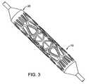
- FIG. 3shows the bifurcation stent of FIG. 1 mounted on a balloon.
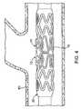
- FIGS. 4-6show the bifurcation stent at the bifurcation site before, during and after expansion.
- FIG. 7shows a two-dimensional representation of another bifurcation stent design, unrolled and flattened.
- FIG. 8shows radiopaque markers on the stent.
- FIG. 8 ashows a two-dimensional representation of another bifurcation stent design lengthened with additional connector struts and with four radiopaque markers.
- FIG. 9shows the mid-stent area of a bifurcation stent first to expand.
- FIG. 10shows a two-dimensional representation of an ostial stent, unrolled and flattened.
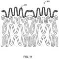
- FIG. 11shows an end portion of the stent in FIG. 10 .
- FIG. 12shows the wings and connecting struts of the stent in FIG. 10 .
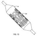
- FIG. 13shows the ostial stent of FIG. 10 mounted on a balloon.
- FIGS. 14-16show an ostial stent at a bifurcation site before, during and after expansion.
- FIGS. 17-19show an ostial stent at a bifurcation site with an angle between the branching vessels, before, during and after expansion.
- FIG. 20illustrates the angle of the flaring portion when disposed on a side of the main body.
- FIG. 21illustrates the angle of the flaring portion when disposed on an end of the main body.
- the present inventionis a balloon expandable stent for bifurcation and ostial lesions.
- the word bifurcation in this patentincludes all types of bifurcation lesions and lesions near bifurcations in the vessels or ostial lesions of all types including aorto-ostial and anastomosis sites.
- the stenthas a tubular structure and comprises a main body that is balloon expandable and is capable of supporting a main vessel. It has a portion which flares at least partially into a side branch vessel and supports the side branch ostium in response to expansion of the main body, without requiring an additional deployment balloon. An additional balloon may be used to complete the deployment if needed.
- FIG. 1An example of a bifurcation stent design 10 is shown in FIG. 1 two-dimensionally, unrolled and flattened. Additional structural features of stent 10 are also illustrated in FIG. 2 and FIG. 3 shows the same stent 10 mounted on a balloon 20 .
- the stent 10 of FIG. 1comprises a structure 11 designed to radially expand and a connector 12 between the radially expandable structure 11 and a flaring portion 13 .
- the radially expandable structure 11is attached to both sides of connector 12 but does not necessarily form a circumferential ring.
- the structure 11expands to support the main vessel while enabling the connector 12 to open.
- Connector 12is designed to have a geometrical preference to deform outwardly rather than along the balloon surface. Once the expandable structure 11 expands and allows the connector 12 to open, connector 12 is deflected outwardly.
- Flaring portion 13 in this examplecomprises two wings 14 shown in FIG. 2 that are interconnected with connecting struts 15 also shown in FIG. 2 . Additional wings may be added. Alternatively, the wings can be replaced with meandering struts or any other strut design. Wings 14 are attached to connectors 12 and are deployed outwardly into the side branch when the connectors 12 deflect. The wings 14 shown in this example are symmetrical although each one can have a different size or design to allow better support of different bifurcation angles. When wings 14 are deployed, connecting struts 15 are pulled and may add more coverage to the side branch ostium.
- the stentfurther comprises another radially expandable structure 16 shown in FIG. 1 that expands due to balloon inflation and supports the main vessel at the mid-stent area. This area can be designed with many different patterns to allow coverage of the main vessel.
- FIGS. 4 , 5 and 6illustrate a bifurcation stent design 10 undergoing the expansion process.
- FIG. 4shows the stent 10 comprising a flaring region 13 crimped over a balloon 20 in a blood vessel (BV)
- FIG. 5shows the stent during expansion where the flaring portion 13 begins to flare in response to main body expansion
- FIG. 6shows the fully expanded stent with the flaring portion 13 extending into a side branch.
- FIG. 20shows ⁇ , the angle of the flaring portion relative to a central axis of the stent, which is in the range from 10 to 150 degrees, and the flaring portion is disposed on a side of the stent main body.
- FIG. 7shows another stent design 100 containing the similar structural features as previously described in FIGS. 1 and 2 , but with dimensions of structural features varied.
- the main stent bodyhas a different stiffness near its proximal and distal ends as compared to the mid-stent region. This causes the center of the stent to expand first during deployment. Deployment of the center of the stent and the flaring portion can be achieved by altering the design of the balloon as shown in FIG. 9 .
- One such exampleis a thinner balloon wall thickness closer to the center of the balloon 21 . This pushes the flaring portion against the side branch ostium and it is deployed inside the side branch. Early expansion of the area near the flaring portion pushes the stent into place before deploying the flaring portion.
- the balloon center area design 21can be controlled by the wall thickness, mold design or thermal treatments of the polymer.
- Varying the radial stiffness of different areas of the stentcan be achieved in various ways.
- One optionis to reduce the width of struts (e.g. 106 ) or their thickness in the stent area that is closest to the flaring portion.
- longer strutsmay be used when lower stiffness is desired.
- Another possible wayis to increase the spacing between intersecting struts in areas where less radial stiffness is desired (e.g. 101 , 106 ).
- the flaring portion structure 13is designed to deploy to a 90 degree angle. In another embodiment the flaring portion 13 is designed to be deployed to various pre-determined angles. In yet another embodiment the flaring portion 13 is tilted at varying angles to fit the bifurcation angle anatomy. An additional way to control the degree of flaring is by applying different inflation pressures to the main body of the balloon used for stent expansion.
- the stentis symmetrical and therefore both wings 14 of the flaring portion 13 deploy in the same way and to the same angle.
- the stent 10may not be symmetrical which causes the distal area of the flaring portion 13 to deploy at a greater angle than the proximal area of the flaring portion 13 . This can be achieved by transmitting less force on the connecting strut 12 at the proximal side which in turn deflects less and therefore lifts the wing 14 to a lower angle.
- An example of a way to transmit less force along the connecting strut 12is to make the radially expandable structure 11 weaker by using radially expandable structure struts that are either longer, thinner or both.
- stiffening connecting strut 12 on the distal sidetransmits more force and therefore deflects more thereby lifting the distal wing 14 to a greater angle than the proximal wing.
- the wings 14may have different designs to allow for different properties and also to maximize other benefits such as selective drug delivery for example.
- the stentmay comprise radiopaque markers to assist accurate positioning of the stent.
- radiopaque markersfabricated from radiopaque materials such as gold, platinum, tantalum and the like, can be attached to the stent 10 at different locations and can be viewed via fluoroscopy.
- FIG. 7shows an example of a stent where the wings 114 of the flaring portion are designed to include a marker welded or otherwise attached to the stent. Preferred locations for these radiopaque markers are the wings 114 of the flaring portion.
- radiopaque markers placed on each of the wings 114 of the flaring portionwill assist the physician in determining where the flaring portion is positioned relative to the side branch before stent expansion as well as helping to position the stent accurately. It will also enable the physician to see the flaring portion deployed into the vessel side branch. This is advantageous because not only does it help the physician to identify the side branch location but also helps in placing a second stent or re-guidewiring the side branch for post deployment treatments of the side branch area.
- Multiple radiopaque markers 308may be attached to the flaring region in order to further enhance visibility as illustrated in FIG. 8 a , which shows four radiopaque markers.
- the stentcan be made from biocompatible alloys such as stainless steel, cobalt chromium, titanium, nickel titanium alloys, niobium alloys or any other material suitable for use in body implants.
- the stentmay further include graft materials such as PTFE or polymer membranes.
- the stentmay be coated with an anti-inflammatory drug or other therapeutic agents with or without a polymer.
- self-expanding materialssuch as nickel titanium alloys is optional but not necessary for the functionality of the stent and the self-opening of the flaring portion.
- the stentcan be made of resorbable or absorbable materials such as different polymer formulations, magnesium alloys and other materials that are resorbable or absorbable under body conditions.
- FIGS. 1 and 2also illustrate another embodiment where the stent 10 comprises three sections, a stent main body, a flaring portion 13 and an optional leverage mechanism 12 or 15 connecting the main body and the flaring portion 13 .
- the leverage mechanism 12 or 15is designed to connect the flaring portion 13 and the main body in a way such that forces and displacement resulting from the partial expansion of the stent main body or the inflation of the main body balloon are transferred and utilized to expand the flaring portion 13 .
- the leverage mechanism 12 or 15may be integrated with the design of the flaring portion 13 or the main body to help deploy the flaring portion 13 once the main body balloon is inflated, and can be fabricated in the same way as the rest of the stent. For example, the entire stent pattern including the side portion and the leverage mechanism may be laser cut from a tube.
- the main body and the flaring portionshare the same pattern or same pattern features. These two portions of the stent are connected by a leverage mechanism with different design features aimed to deploy the flaring portion by leveraging the geometrical changes and forces resulting from the main body expansion.
- the flaring portion expansionoccurs before the completion of the main body expansion.
- the side branch portion expansionhelps the positioning and the alignment of the stent in the bifurcation area and allows the stent system to acquire the angle of the bifurcation and comply with the local anatomy.
- the main body of the stenthas more than a single pattern.
- the area of the stent that is close to the flaring portionhas a different pattern than the areas of the stent that are further away from the flaring portion.
- the flaring portionmay have either one of these patterns, a different pattern or no pattern at all.
- the stent designallows the use of a delivery system with a single balloon without the need for additional means for deploying the flaring portion.
- the profile of the systemcan be very low as compared to other bifurcation stent systems and is typically lower than 0.06,′′ preferably lower than 0.05′′ and usually lower than 0.04′′ which is a typical profile of conventional stents not dedicated to bifurcation lesions. This low profile can be achieved due to the design of the stent and the automatically deployed flaring portion.
- the stentcan be coated with various coatings including biocompatible oxide layers such as Ir oxide and the like, drug containing polymer coatings whether biodegradable or not, or drug molecules, that can help reduce restenosis or minimize inflammation or impact biological processes in the vessel with a beneficial outcome for the patient.
- biocompatible oxide layerssuch as Ir oxide and the like
- drug containing polymer coatingswhether biodegradable or not, or drug molecules, that can help reduce restenosis or minimize inflammation or impact biological processes in the vessel with a beneficial outcome for the patient.
- the stenthas a crimped configuration and an expanded configuration.
- the flaring portionis crimped with the stent but is not necessarily flush with the crimped main stent body because struts in the flaring portion are not necessarily flush with the crimped cylindrical surface of the stent.
- the flaring portioncan be crimped flush with the main body of the stent.
- the stenthas a crimped configuration and an expanded configuration, whereas in the crimped configuration the proximal and distal ends of the stent are crimped to a smaller diameter than the middle area of the stent.
- FIG. 8 aillustrates a bifurcation stent 300 two-dimensionally, unrolled and flattened.
- the stent 300 of FIG. 8 acomprises two radially expandable circumferential ring structures 301 designed to radially expand and a U-shaped connector 302 which connects the radially expandable circumferential ring structures 301 and wings 313 which comprise the flaring portion of the stent 300 .
- each connector 302is disposed within and forms part of the radially expandable circumferential ring structure 301 which expands to support the main vessel while causing legs 303 of connector 302 to open.
- Connector 302is designed to have a geometrical preference to deform outwardly rather than along the balloon surface. Once the expandable structure 301 expands and allows the connector 302 to open, connector 302 is deflected outwardly.
- a flaring portion of the stentcomprises four wings 313 shown in FIG. 8 a that are interconnected with connecting struts 305 which also flare and form part of the flaring portion.
- the wings 313each have a base 314 which is attached to a cross-member 304 of each connector 302 , and the wings 313 are deployed outwardly into the side branch when the connectors 302 deflect.
- the wings 313 shown in this exampleare symmetrical although each one can have a different size or design to allow better support of different bifurcation angles. When wings 313 are deployed, connecting struts 305 are pulled inward and may add more coverage to the side branch ostium.
- the stentfurther comprises another radially expandable structure 306 shown in FIG. 8 a that expands due to balloon inflation and supports the main vessel at the mid-stent area.
- This areacan be designed with many different patterns to allow for coverage of the main vessel.
- Wings 313have also been modified so that the stent may further comprise radiopaque markers to assist accurate positioning of the stent.
- radiopaque markers 308fabricated from radiopaque materials such as gold, platinum, tantalum and the like, can be attached to the stent 300 on the wings 313 .
- the markers 308may be attached to the wings 313 by swaging, welding, or fusing, for example.
- markers 308are advantageous because they assist the physician in viewing the flaring portion of the stent relative to the side branch before stent expansion as well as helping to position the stent more accurately. It will also enable the physician to see the flaring portion deployed into the vessel side branch. This is advantageous because not only does it help the physician to identify the side branch location but also helps in placing a second stent or re-guidewiring the side branch for post deployment treatments of the side branch area. Additionally, having four markers on the stent enables the physician to determine the stent rotational orientation under fluoroscopy prior to stent deployment. When all four markers can be detected, this is an indication that the stent side portion is either facing the fluoroscopy screen or facing 180 degrees the other way. The physician can then torque the device and rotate it until only two markers are observed, indicating a side view, facing the ostium direction thereby confirming that the stent is properly aligned for deployment.
- the basic stent design described hereinresults in a relatively short stent, typically six to eight millimeters long.
- the architecture of the stentcan be designed to foreshorten during stent deployment and cause movement of the struts toward the bifurcation area resulting in more support to the bifurcation area.
- the average lesion lengthis about 15 millimeters and most lesions are in the range of 10 to 20 millimeters.
- Placing a short stent at the bifurcation siteoften will require placing additional stents both proximally and distally to the bifurcation stent. This is difficult and undesirable since additional stents may entangle as they pass through the delivered stent. For this reason, it is desirable to add length to the stent both proximally and distally and provide stent designs that vary in length typically between 10 and 20 millimeters.
- An additional lengthening structurecan be added to the stent symmetrically around the side portion or may be added to proximal or distal sections of the stent. This additional structure can be designed with many different geometries that support a vessel wall.
- a common designfor example comprises rows of sinusoidal rings that are radially collapsed prior to expansion and radially opened upon balloon expansion. These sinusoidal rings are commonly interconnected with a variety of connector designs.
- the connector designeither allows stent foreshortening during expansion or the connector design allows stent lengthening during expansion. For example, when rows of sinusoidal rings are placed peak-to-peak and a connector joins adjacent peaks of the rows, the stent will foreshorten during expansion. On the other hand, if the adjacent rings are interconnected with a connector between adjacent valleys, the stent will lengthen during expansion.
- additional rowsmay be added to produce a stent that lengthens during expansion to compensate for foreshortening around the stent side portion and provides a length in the range of 10 to 20 millimeters.
- FIG. 8 aillustrates additional struts 310 which connect adjacent radially expandable structures 301 so that the stent lengthens during expansion, as describe above.
- FIG. 8 ashows the radially expandable structures 301 symmetrical on both side of the stent 300 .
- either the proximal or distal endmay comprise additional radially expandable structures 301 with a strut 310 in between adjacent radially expandable structures 301 to produce varying length stents.
- all of the modifications and variations discussed above for other bifurcation stentsmay be applied to the embodiment of FIG. 8 a.
- the stent 200 of FIG. 10has a crimped configuration and an expanded configuration.
- the proximal area of the stentis crimped to a first diameter and the distal area of the stent is crimped to a second, smaller diameter.
- the proximal area of the flaring portion 203is flush with the stent proximal area and distal area of the flaring portion 203 is also flush with the stent distal area.
- FIGS. 10-13An example of such a stent design 200 is shown in FIGS. 10-13 , where FIGS. 10-12 shows a two-dimensional view of the stent 200 and FIG. 13 shows the same stent 200 mounted on a balloon 20 .
- FIGS. 10-13describe an example of an ostial stent design 200 , similar to the bifurcation design 10 previously discussed.
- the ostial stent design 200comprises a structure 201 shown in FIG. 10 which is designed to expand, a connector 202 that connects between the radially expandable structure 201 , and an edge portion 203 shown in FIG. 11 .
- the radially expandable structure 201is made of elements that do not necessarily form a circumferential ring and hang on both sides of the connector 202 .
- the structureexpands to support the side branch vessel while enabling the connector 202 to open.
- Connector 202is designed to have a geometrical preference to deform outwardly rather than along the balloon surface. Once the expandable structure 201 expands and allows the connector 202 to open, the connector 202 is deflected outwardly.
- the edge portion 203comprises two wings 204 shown in FIG. 12 that are interconnected with connecting struts 205 . These wings 204 are located on the connectors 202 and are deployed outwardly into the side branch ostium when the connectors 202 deflect.
- the wings 204 shown in this exampleare symmetrical although each one can have different size or design to allow better support of different bifurcation angles.
- An example of an alternate wing designcomprises meandering struts. When the wings 204 are deployed, the connecting struts 205 are pulled and may provide more coverage to the side branch ostium.
- the stent 200further comprises another radially expandable structure 206 shown in FIG. 10 that expands due to inflation of the balloon and supports the side branch vessel at the stent area close to the ostium.
- This area of the stentcan be designed with many different patterns to allow coverage of the side branch vessel.
- the stentmay consist an array of connectors 202 attached directly to each other without the expandable structure 201 .
- the stent 200may include more then two connectors 202 .
- the number of connectorsmay be two to six, or more.
- FIGS. 14-16illustrate the process of ostial stent expansion.
- FIG. 14shows the stent 200 crimped over a balloon 20 in a blood vessel BV while
- FIG. 15shows the stent edge portion 203 deployed after the stent 200 has been expanded.
- FIG. 16shows the fully expanded stent 200 after the balloon 20 is withdrawn.
- FIG. 21shows ⁇ , the angle of the flaring portion relative to a central axis of the stent, and is in the range from 10 to 150 degrees.
- the flaring portionis disposed on an end of the stent main body.
- the main stent bodyhas a different stiffness near the distal end than the area of the stent closer to the ostium. This results in the stent area closer to the ostium to expand first.
- Deployment of the distal area of the stent and the edge portioncan be achieved by altering the design of the balloon to have a larger diameter at the edge portion area.
- Another exampleis a thinner balloon wall thickness closer to the edge portion of the stent. This way the edge portion is pushed against the side branch ostium. Early expansion of the area near the edge portion pushes the stent into position before deploying the stent main body.
- Balloon distal area designcan be controlled by the wall thickness, mold design or thermal treatments of the polymer.
- Differences in the radial stiffness in different regions of the stentcan be achieved by various means.
- One optionis to reduce strut width or thickness in the stent area closest to the edge portion.
- Another optionis to use longer struts where lower stiffness is desired.
- Another possible wayis to increase the spacing between intersecting struts in areas where less radial stiffness is desired.
- the edge portion structureis designed to deploy to a 90 degree angle.
- the edge portionis designed to be deployed in various pre-determined angles.
- the edge portionmay be tilted at different angle to accommodate small bifurcation angle anatomy.
- An additional way to control the degree of flaringis by applying different inflation pressures to different sections of the stent with the balloon used for stent expansion.
- the stentis symmetrical and both wings 204 of the edge portion 203 deploy the same way and at the same angle.
- the stentmay not be symmetrical, thus the distal area of the edge portion 203 deploys at a greater angle relative to the proximal area of the flaring portion. This can be achieved by transmitting less force on the connecting strut 202 at the proximal side which in turn will deflect less and lift the wing 204 to a lesser angle.
- FIGS. 14-16show the wings 204 opposed to one another. The number of wings can vary from one to eight wings, preferably two to four wings.
- the ostium morphologyis not cylindrically symmetrical as shown in FIGS. 17-19 .
- the stent 200may have an angulated geometry, meaning that the crimped stent profile is cut at an angle at the proximal end ( FIG. 17 ).
- the wings 204may be gradual and asymmetrical around the stent axis, thus one wing is closer to the stent distal end than the other.
- the wings 204comply with the ostium angulation as shown in FIGS. 17-19 .
- the wingscan also differ in length since the distal side of the ostium is longer than the proximal side.
- the profile of the distal side of the ostiumis different than the profile of the proximal side of the ostium.
- the wingscan assume the same or different profiles in order to accommodate different ostial regions.
- the stentmay comprise radiopaque markers similar to 30 in another embodiment, to assist with accurate positioning of the stent.
- An exampleis a radiopaque marker made from radiopaque material such as gold, platinum, tantalum and the like, that can be attached to the stent at different locations and can be viewed via fluoroscopy.
- Preferred locations for these radiopaque markersare the wings 204 of the edge portion. Having radiopaque markers placed on each of the wings 204 of the flaring portion will assist the physician in determining where the edge portion 203 is positioned relative to the ostium before stent expansion as well as helping to position the stent accurately. It will also enable the physician to see the edge portion 203 deployed over the ostium. This is advantageous because not only does it help the physician to identify the side branch location but also helps in placing a second stent or re-guidewiring the side branch for post deployment treatments of the side branch area.
- the stentcan be made from biocompatible alloys such as stainless steel, cobalt chromium, titanium, nickel titanium alloys, niobium alloys or any other material suitable for use in body implants.
- the stentmay further include graft materials such as PTFE or polymer membranes.
- the stentmay be coated with anti-inflammatory drug or other therapeutic agents with or without a polymer.
- self-expanding materialssuch as nickel titanium alloys is optional but not necessary for the functionality of the stent and the self-opening of the edge portion.
- the stentcan be made of resorbable or absorbable materials such as different polymer formulations, magnesium alloys and other materials that are resorbable or absorbable under body conditions.
- the stent 200comprises three sections, a main stent body, an edge portion 203 and an optional leverage mechanism 202 or 205 connecting the main body and edge portion 203 .
- the leverage mechanism 202 or 205is designed to connect the edge 203 portion and the main body in a way such that forces and displacement resulting from the partial expansion of the main body or the inflation of the main body balloon are transferred and utilized to expand the edge portion 203 .
- the leverage mechanism 202 or 205can be integrated with the design of the edge portion 203 or the main body to help deploy the edge portion 203 once the main body balloon is inflated, and can be fabricated in the same way as the rest of the stent.
- the entire stent pattern including the side portion and the leverage mechanismmay be laser cut from a tube.
- the main body and the edge portionshare the same pattern or same pattern features. These two portions of the stent are connected by a leverage mechanism with different design features aimed to deploy the edge portion by leveraging the geometrical changes and forces resulting from the main body expansion.
- the edge portion expansionoccurs before the completion of the main body expansion. This helps with positioning and alignment of the stent in the bifurcation area, allows the stent system to acquire the angle of the bifurcation and helps to comply with the local anatomy.
- the main body of the stenthas more than a single pattern.
- the area of the stent that is close to the location of the edge portionhas a different pattern than areas of the stent further away from the edge portion.
- the edge portionmay have either one of those patterns, a different pattern or no pattern at all.
- the stent designallows the use of a delivery system with a single balloon without the need for additional means for deploying the edge portion.
- the profile of the systemcan be very low when compared to other bifurcation or ostial stent systems and is typically lower than 0.06,′′ preferably lower than 0.05′′ and usually lower than 0.04′′ which is a typical profile of conventional stents not dedicated to bifurcation or ostial lesions. This low profile can be achieved due to the design of the stent and the automatically deployed edge portion.
- the stentcan be coated with various coatings including biocompatible oxide layer such as Ir oxide and the like, drug containing polymer coatings whether biodegradable or not, or drug molecules, that can help reduce restenosis or minimize inflammations or impact biological processes in the vessel with a beneficial outcome for the patient.
- biocompatible oxide layersuch as Ir oxide and the like
- drug containing polymer coatingswhether biodegradable or not, or drug molecules, that can help reduce restenosis or minimize inflammations or impact biological processes in the vessel with a beneficial outcome for the patient.
- the stenthas a crimped configuration and an expanded configuration.
- the edge portionis crimped with the stent but is not necessarily flush with the crimped main body because the struts of the edge portion are not necessarily flush with the crimped cylindrical stent surface.
- the edge portionmay be crimped flush with the main body of the stent.
- the proximal or distal ends of the stentare crimped to a smaller diameter then the middle area of the stent.
- the methods, catheters, and systems of the present inventioncan be utilized to deliver a wide variety of active substances, including drugs useful for treating a wide variety of luminal diseases and conditions.
- the methods and apparatus of the present inventionare particularly useful for delivering a wide variety of therapeutic and pharmaceutical agents, referred to collectively herein as active substances, particularly those suitable for treating vascular and other luminal conditions.
- active substancesparticularly those suitable for treating vascular and other luminal conditions.
- antiproliferative and antimitotic agentssuch as paclitaxel or others, anti-inflammatory agents, immunosuppressive agents such as sirolimus (rapamycin) or others, antiproliferative and antimitotic antimetabolites such as folic acid analogs and any other therapeutic agent that can add benefit to the patient.
- the active substancemay be provided on or within the stent in a variety of ways.
- the active substancemay be coated over at least a portion of an exposed surface of the stent, typically by dipping, spraying, painting, plasma deposition, electroplating, centrifuge systems or the like. More typically, however, the active substance may be incorporated in a polymeric carrier. Suitable polymeric carriers may be resorbable, such as those comprising polylactic acids (PLA), polyglycolic acids (PLG), collagens, and the like. Alternatively, the polymeric carrier may be a porous but non-resorbable material.
Landscapes
- Health & Medical Sciences (AREA)
- Engineering & Computer Science (AREA)
- Biomedical Technology (AREA)
- Cardiology (AREA)
- Oral & Maxillofacial Surgery (AREA)
- Transplantation (AREA)
- Heart & Thoracic Surgery (AREA)
- Vascular Medicine (AREA)
- Life Sciences & Earth Sciences (AREA)
- Animal Behavior & Ethology (AREA)
- General Health & Medical Sciences (AREA)
- Public Health (AREA)
- Veterinary Medicine (AREA)
- Physics & Mathematics (AREA)
- Optics & Photonics (AREA)
- Media Introduction/Drainage Providing Device (AREA)
- Prostheses (AREA)
Abstract
Description
Claims (11)
Priority Applications (3)
| Application Number | Priority Date | Filing Date | Title |
|---|---|---|---|
| US11/330,382US9114033B2 (en) | 2005-01-10 | 2006-01-10 | Stent with self-deployable portion |
| US12/390,202US9101500B2 (en) | 2005-01-10 | 2009-02-20 | Stent with self-deployable portion having wings of different lengths |
| US12/938,133US20110270386A1 (en) | 2005-01-10 | 2010-11-02 | Stent with self-deployable portion having wings of different lengths |
Applications Claiming Priority (5)
| Application Number | Priority Date | Filing Date | Title |
|---|---|---|---|
| US64306205P | 2005-01-10 | 2005-01-10 | |
| US68445405P | 2005-05-24 | 2005-05-24 | |
| US71294905P | 2005-08-30 | 2005-08-30 | |
| US74093505P | 2005-11-29 | 2005-11-29 | |
| US11/330,382US9114033B2 (en) | 2005-01-10 | 2006-01-10 | Stent with self-deployable portion |
Related Child Applications (1)
| Application Number | Title | Priority Date | Filing Date |
|---|---|---|---|
| US12/390,202Continuation-In-PartUS9101500B2 (en) | 2005-01-10 | 2009-02-20 | Stent with self-deployable portion having wings of different lengths |
Publications (2)
| Publication Number | Publication Date |
|---|---|
| US20060173528A1 US20060173528A1 (en) | 2006-08-03 |
| US9114033B2true US9114033B2 (en) | 2015-08-25 |
Family
ID=36648274
Family Applications (1)
| Application Number | Title | Priority Date | Filing Date |
|---|---|---|---|
| US11/330,382Expired - Fee RelatedUS9114033B2 (en) | 2005-01-10 | 2006-01-10 | Stent with self-deployable portion |
Country Status (6)
| Country | Link |
|---|---|
| US (1) | US9114033B2 (en) |
| EP (1) | EP1835866B1 (en) |
| JP (1) | JP4979591B2 (en) |
| CN (1) | CN101102728B (en) |
| AT (1) | ATE508714T1 (en) |
| WO (1) | WO2006074476A2 (en) |
Cited By (3)
| Publication number | Priority date | Publication date | Assignee | Title |
|---|---|---|---|---|
| US20160067067A1 (en)* | 2014-09-10 | 2016-03-10 | The Cleveland Clinic Foundation | Frame structures, stent grafts incorporating the same, and methods for extended aortic repair |
| US11076945B2 (en) | 2017-10-07 | 2021-08-03 | The Cleveland Clinic Foundation | Endovascular grafts and methods for extended aortic repair |
| US11793961B2 (en) | 2016-10-18 | 2023-10-24 | University of Pittsburgh—of the Commonwealth System of Higher Education | Esophageal temporary occlusion device and method for endotracheal intubation and orogastric tube insertion |
Families Citing this family (91)
| Publication number | Priority date | Publication date | Assignee | Title |
|---|---|---|---|---|
| US7341598B2 (en) | 1999-01-13 | 2008-03-11 | Boston Scientific Scimed, Inc. | Stent with protruding branch portion for bifurcated vessels |
| US6325826B1 (en)* | 1998-01-14 | 2001-12-04 | Advanced Stent Technologies, Inc. | Extendible stent apparatus |
| EP1723931B1 (en)* | 1996-11-04 | 2012-01-04 | Advanced Stent Technologies, Inc. | Extendible stent apparatus and method for deploying the same |
| US6835203B1 (en) | 1996-11-04 | 2004-12-28 | Advanced Stent Technologies, Inc. | Extendible stent apparatus |
| US6599316B2 (en)* | 1996-11-04 | 2003-07-29 | Advanced Stent Technologies, Inc. | Extendible stent apparatus |
| US8257425B2 (en) | 1999-01-13 | 2012-09-04 | Boston Scientific Scimed, Inc. | Stent with protruding branch portion for bifurcated vessels |
| US20030097169A1 (en) | 2001-02-26 | 2003-05-22 | Brucker Gregory G. | Bifurcated stent and delivery system |
| US8298280B2 (en) | 2003-08-21 | 2012-10-30 | Boston Scientific Scimed, Inc. | Stent with protruding branch portion for bifurcated vessels |
| US8007528B2 (en) | 2004-03-17 | 2011-08-30 | Boston Scientific Scimed, Inc. | Bifurcated stent |
| JP5054524B2 (en) | 2004-06-08 | 2012-10-24 | アドバンスド ステント テクノロジーズ, インコーポレイテッド | Stent with protruding branch for branch pipe |
| US9427340B2 (en)* | 2004-12-14 | 2016-08-30 | Boston Scientific Scimed, Inc. | Stent with protruding branch portion for bifurcated vessels |
| US9101500B2 (en)* | 2005-01-10 | 2015-08-11 | Trireme Medical, Inc. | Stent with self-deployable portion having wings of different lengths |
| US8652193B2 (en) | 2005-05-09 | 2014-02-18 | Angiomed Gmbh & Co. Medizintechnik Kg | Implant delivery device |
| US8317855B2 (en) | 2005-05-26 | 2012-11-27 | Boston Scientific Scimed, Inc. | Crimpable and expandable side branch cell |
| US8480728B2 (en) | 2005-05-26 | 2013-07-09 | Boston Scientific Scimed, Inc. | Stent side branch deployment initiation geometry |
| US20070050016A1 (en)* | 2005-08-29 | 2007-03-01 | Boston Scientific Scimed, Inc. | Stent with expanding side branch geometry |
| US7731741B2 (en)* | 2005-09-08 | 2010-06-08 | Boston Scientific Scimed, Inc. | Inflatable bifurcation stent |
| US8038706B2 (en) | 2005-09-08 | 2011-10-18 | Boston Scientific Scimed, Inc. | Crown stent assembly |
| US8043366B2 (en) | 2005-09-08 | 2011-10-25 | Boston Scientific Scimed, Inc. | Overlapping stent |
| US20070112418A1 (en)* | 2005-11-14 | 2007-05-17 | Boston Scientific Scimed, Inc. | Stent with spiral side-branch support designs |
| US8343211B2 (en) | 2005-12-14 | 2013-01-01 | Boston Scientific Scimed, Inc. | Connectors for bifurcated stent |
| US8435284B2 (en) | 2005-12-14 | 2013-05-07 | Boston Scientific Scimed, Inc. | Telescoping bifurcated stent |
| US20070142904A1 (en)* | 2005-12-20 | 2007-06-21 | Boston Scientific Scimed, Inc. | Bifurcated stent with multiple locations for side branch access |
| US7540881B2 (en) | 2005-12-22 | 2009-06-02 | Boston Scientific Scimed, Inc. | Bifurcation stent pattern |
| US20070156230A1 (en) | 2006-01-04 | 2007-07-05 | Dugan Stephen R | Stents with radiopaque markers |
| US20070208419A1 (en)* | 2006-03-06 | 2007-09-06 | Boston Scientific Scimed, Inc. | Bifurcation stent with uniform side branch projection |
| US7833264B2 (en)* | 2006-03-06 | 2010-11-16 | Boston Scientific Scimed, Inc. | Bifurcated stent |
| US20070208415A1 (en)* | 2006-03-06 | 2007-09-06 | Kevin Grotheim | Bifurcated stent with controlled drug delivery |
| US8298278B2 (en) | 2006-03-07 | 2012-10-30 | Boston Scientific Scimed, Inc. | Bifurcated stent with improvement securement |
| US20070225798A1 (en)* | 2006-03-23 | 2007-09-27 | Daniel Gregorich | Side branch stent |
| US8348991B2 (en)* | 2006-03-29 | 2013-01-08 | Boston Scientific Scimed, Inc. | Stent with overlap and high expansion |
| US8043358B2 (en)* | 2006-03-29 | 2011-10-25 | Boston Scientific Scimed, Inc. | Stent with overlap and high extension |
| US20070260304A1 (en)* | 2006-05-02 | 2007-11-08 | Daniel Gregorich | Bifurcated stent with minimally circumferentially projected side branch |
| US20130325107A1 (en) | 2006-05-26 | 2013-12-05 | Abbott Cardiovascular Systems Inc. | Stents With Radiopaque Markers |
| EP2051673A2 (en) | 2006-06-23 | 2009-04-29 | Boston Scientific Limited | Bifurcated stent with twisted hinges |
| US20080065200A1 (en)* | 2006-09-07 | 2008-03-13 | Trireme Medical, Inc. | Bifurcated prostheses having differential drug coatings |
| US8216267B2 (en) | 2006-09-12 | 2012-07-10 | Boston Scientific Scimed, Inc. | Multilayer balloon for bifurcated stent delivery and methods of making and using the same |
| US7951191B2 (en) | 2006-10-10 | 2011-05-31 | Boston Scientific Scimed, Inc. | Bifurcated stent with entire circumferential petal |
| US8206429B2 (en) | 2006-11-02 | 2012-06-26 | Boston Scientific Scimed, Inc. | Adjustable bifurcation catheter incorporating electroactive polymer and methods of making and using the same |
| US7842082B2 (en)* | 2006-11-16 | 2010-11-30 | Boston Scientific Scimed, Inc. | Bifurcated stent |
| US20080177377A1 (en)* | 2006-11-16 | 2008-07-24 | Boston Scientific Scimed, Inc. | Bifurcation Stent Design with Over Expansion Capability |
| US8414525B2 (en) | 2006-11-20 | 2013-04-09 | Lutonix, Inc. | Drug releasing coatings for medical devices |
| US20080276935A1 (en) | 2006-11-20 | 2008-11-13 | Lixiao Wang | Treatment of asthma and chronic obstructive pulmonary disease with anti-proliferate and anti-inflammatory drugs |
| US9737640B2 (en) | 2006-11-20 | 2017-08-22 | Lutonix, Inc. | Drug releasing coatings for medical devices |
| US8425459B2 (en) | 2006-11-20 | 2013-04-23 | Lutonix, Inc. | Medical device rapid drug releasing coatings comprising a therapeutic agent and a contrast agent |
| US8414910B2 (en) | 2006-11-20 | 2013-04-09 | Lutonix, Inc. | Drug releasing coatings for medical devices |
| US8414526B2 (en) | 2006-11-20 | 2013-04-09 | Lutonix, Inc. | Medical device rapid drug releasing coatings comprising oils, fatty acids, and/or lipids |
| US20080175887A1 (en) | 2006-11-20 | 2008-07-24 | Lixiao Wang | Treatment of Asthma and Chronic Obstructive Pulmonary Disease With Anti-proliferate and Anti-inflammatory Drugs |
| US9700704B2 (en) | 2006-11-20 | 2017-07-11 | Lutonix, Inc. | Drug releasing coatings for balloon catheters |
| US8998846B2 (en) | 2006-11-20 | 2015-04-07 | Lutonix, Inc. | Drug releasing coatings for balloon catheters |
| US20080147174A1 (en)* | 2006-12-11 | 2008-06-19 | Trireme Medical, Inc. | Apparatus and method of using markers to position stents in bifurcations |
| US7959668B2 (en)* | 2007-01-16 | 2011-06-14 | Boston Scientific Scimed, Inc. | Bifurcated stent |
| US8118861B2 (en) | 2007-03-28 | 2012-02-21 | Boston Scientific Scimed, Inc. | Bifurcation stent and balloon assemblies |
| US8647376B2 (en) | 2007-03-30 | 2014-02-11 | Boston Scientific Scimed, Inc. | Balloon fold design for deployment of bifurcated stent petal architecture |
| US20080300671A1 (en)* | 2007-06-04 | 2008-12-04 | Gil Vardi | Stent having high expansion ratio |
| WO2009029674A1 (en)* | 2007-08-27 | 2009-03-05 | Boston Scientific Limited | Bulging balloon for bifurcation catheter assembly and methods |
| US7959669B2 (en)* | 2007-09-12 | 2011-06-14 | Boston Scientific Scimed, Inc. | Bifurcated stent with open ended side branch support |
| US7833266B2 (en) | 2007-11-28 | 2010-11-16 | Boston Scientific Scimed, Inc. | Bifurcated stent with drug wells for specific ostial, carina, and side branch treatment |
| US10166127B2 (en) | 2007-12-12 | 2019-01-01 | Intact Vascular, Inc. | Endoluminal device and method |
| US10022250B2 (en) | 2007-12-12 | 2018-07-17 | Intact Vascular, Inc. | Deployment device for placement of multiple intraluminal surgical staples |
| US7896911B2 (en) | 2007-12-12 | 2011-03-01 | Innovasc Llc | Device and method for tacking plaque to blood vessel wall |
| US8128677B2 (en) | 2007-12-12 | 2012-03-06 | Intact Vascular LLC | Device and method for tacking plaque to a blood vessel wall |
| US8277501B2 (en) | 2007-12-21 | 2012-10-02 | Boston Scientific Scimed, Inc. | Bi-stable bifurcated stent petal geometry |
| US8747456B2 (en) | 2007-12-31 | 2014-06-10 | Boston Scientific Scimed, Inc. | Bifurcation stent delivery system and methods |
| US9486345B2 (en)* | 2008-01-03 | 2016-11-08 | Covidien Lp | Methods and systems for placement of a stent adjacent an ostium |
| US8932340B2 (en) | 2008-05-29 | 2015-01-13 | Boston Scientific Scimed, Inc. | Bifurcated stent and delivery system |
| CA2757072A1 (en)* | 2009-04-02 | 2010-10-07 | The Medical Research, Infrastructure, And Health Services Fund Of The Tel Aviv Medical Center | Stent graft fenestration |
| EP2528537A4 (en)* | 2010-01-27 | 2016-09-07 | Vascular Therapies Inc | DEVICE AND METHOD FOR PREVENTING STENOSIS ON ANASTOMOSIS SITE |
| US8808353B2 (en) | 2010-01-30 | 2014-08-19 | Abbott Cardiovascular Systems Inc. | Crush recoverable polymer scaffolds having a low crossing profile |
| US8568471B2 (en) | 2010-01-30 | 2013-10-29 | Abbott Cardiovascular Systems Inc. | Crush recoverable polymer scaffolds |
| ES2707987T3 (en)* | 2010-07-08 | 2019-04-08 | Intact Vascular Inc | Deployment device for placement of multiple intraluminal surgical staples |
| CN102525701B (en)* | 2010-12-21 | 2015-06-17 | 先健科技(深圳)有限公司 | Absorbable blood vessel stent |
| US10285831B2 (en) | 2011-06-03 | 2019-05-14 | Intact Vascular, Inc. | Endovascular implant |
| US8726483B2 (en) | 2011-07-29 | 2014-05-20 | Abbott Cardiovascular Systems Inc. | Methods for uniform crimping and deployment of a polymer scaffold |
| EP2967930B1 (en)* | 2013-03-13 | 2018-11-28 | Boston Scientific Scimed, Inc. | Anti-migration tissue anchoring system for a fully covered stent |
| US10709587B2 (en)* | 2013-11-05 | 2020-07-14 | Hameem Unnabi Changezi | Bifurcated stent and delivery system |
| WO2015075708A1 (en) | 2013-11-19 | 2015-05-28 | Endospan Ltd. | Stent system with radial-expansion locking |
| CN104116580A (en)* | 2014-07-22 | 2014-10-29 | 北京航空航天大学 | Intravascular stent |
| CN106029005B (en)* | 2014-12-18 | 2018-01-19 | 恩都思潘有限公司 | The Endovascular stent-graft of horizontal conduit with tired resistance |
| US9375336B1 (en) | 2015-01-29 | 2016-06-28 | Intact Vascular, Inc. | Delivery device and method of delivery |
| US9433520B2 (en) | 2015-01-29 | 2016-09-06 | Intact Vascular, Inc. | Delivery device and method of delivery |
| US9999527B2 (en) | 2015-02-11 | 2018-06-19 | Abbott Cardiovascular Systems Inc. | Scaffolds having radiopaque markers |
| US9700443B2 (en) | 2015-06-12 | 2017-07-11 | Abbott Cardiovascular Systems Inc. | Methods for attaching a radiopaque marker to a scaffold |
| CN106581784B (en)* | 2015-10-19 | 2020-07-17 | 先健科技(深圳)有限公司 | Absorbable Iron-Based Alloy Implantable Medical Devices |
| US10993824B2 (en) | 2016-01-01 | 2021-05-04 | Intact Vascular, Inc. | Delivery device and method of delivery |
| US11660218B2 (en) | 2017-07-26 | 2023-05-30 | Intact Vascular, Inc. | Delivery device and method of delivery |
| US10779929B2 (en)* | 2017-10-06 | 2020-09-22 | J.D. Franco & Co., Llc | Treating eye diseases by deploying a stent |
| CN108095857A (en)* | 2017-12-18 | 2018-06-01 | 上海脉全医疗器械有限公司 | A kind of biodegradable stent system for crotch vascular lesion |
| CN107951603A (en)* | 2017-12-18 | 2018-04-24 | 上海脉全医疗器械有限公司 | A kind of biodegradable stent system for crotch branch vessel |
| WO2019236900A1 (en)* | 2018-06-08 | 2019-12-12 | Efemoral Medical Llc. | Absorbable intravascular devices that shorten upon expansion creating space for vascular movement |
| US11318030B1 (en)* | 2018-08-14 | 2022-05-03 | Archana Venkatesan | Stent assembly for use in treating bifurcation lesions and methods of making and using the same |
Citations (54)
| Publication number | Priority date | Publication date | Assignee | Title |
|---|---|---|---|---|
| US4994071A (en) | 1989-05-22 | 1991-02-19 | Cordis Corporation | Bifurcating stent apparatus and method |
| US5147332A (en) | 1991-05-17 | 1992-09-15 | C.R. Bard, Inc. | Multi-valve catheter for improved reliability |
| US5607444A (en) | 1993-12-02 | 1997-03-04 | Advanced Cardiovascular Systems, Inc. | Ostial stent for bifurcations |
| US5609627A (en) | 1994-02-09 | 1997-03-11 | Boston Scientific Technology, Inc. | Method for delivering a bifurcated endoluminal prosthesis |
| DE29701758U1 (en) | 1997-02-01 | 1997-03-27 | Jomed Implantate GmbH, 72414 Rangendingen | Radially expandable stent for implantation in a body vessel, particularly in the area of a vascular branch |
| DE29708803U1 (en) | 1997-05-17 | 1997-07-31 | Jomed Implantate GmbH, 72414 Rangendingen | Radially expandable stent for implantation in a body vessel in the area of a vascular branch |
| EP0800801A1 (en) | 1996-04-10 | 1997-10-15 | Advanced Cardiovascular Systems, Inc. | Stent having varied amounts of structural strength along its length |
| US5749825A (en) | 1996-09-18 | 1998-05-12 | Isostent, Inc. | Means method for treatment of stenosed arterial bifurcations |
| US5755735A (en) | 1996-05-03 | 1998-05-26 | Medinol Ltd. | Bifurcated stent and method of making same |
| US5827229A (en) | 1995-05-24 | 1998-10-27 | Boston Scientific Corporation Northwest Technology Center, Inc. | Percutaneous aspiration thrombectomy catheter system |
| US5882329A (en) | 1997-02-12 | 1999-03-16 | Prolifix Medical, Inc. | Apparatus and method for removing stenotic material from stents |
| US5928248A (en) | 1997-02-14 | 1999-07-27 | Biosense, Inc. | Guided deployment of stents |
| WO2000044319A1 (en) | 1999-01-27 | 2000-08-03 | Disc-O-Tech Medical Technologies, Ltd. | Expandable intervertebral spacer |
| US6099497A (en) | 1998-03-05 | 2000-08-08 | Scimed Life Systems, Inc. | Dilatation and stent delivery system for bifurcation lesions |
| US6165195A (en) | 1997-08-13 | 2000-12-26 | Advanced Cardiovascylar Systems, Inc. | Stent and catheter assembly and method for treating bifurcations |
| US6210429B1 (en) | 1996-11-04 | 2001-04-03 | Advanced Stent Technologies, Inc. | Extendible stent apparatus |
| US6293964B1 (en)* | 1997-03-26 | 2001-09-25 | Jay S. Yadav | Ostial stent |
| US6325826B1 (en) | 1998-01-14 | 2001-12-04 | Advanced Stent Technologies, Inc. | Extendible stent apparatus |
| US20020143386A1 (en)* | 2001-03-29 | 2002-10-03 | Davila Luis A. | Radiopacity intraluminal medical device |
| US20020173835A1 (en) | 1999-06-04 | 2002-11-21 | Advanced Stent Technologies, Llc | Short sleeve stent delivery catheter and methods |
| WO2003020173A1 (en) | 2001-09-04 | 2003-03-13 | Graeme Cocks | A stent |
| US20030083734A1 (en)* | 2001-10-25 | 2003-05-01 | Curative Ag | Stent |
| US6579309B1 (en)* | 1999-08-06 | 2003-06-17 | Biotronik Mess-Und Therapiegerate Gmbh & Co. Ingenieurburo Berlin | Stent for vessel branchings |
| US6596011B2 (en) | 2001-06-12 | 2003-07-22 | Cordis Corporation | Emboli extraction catheter and vascular filter system |
| US6596020B2 (en) | 1996-11-04 | 2003-07-22 | Advanced Stent Technologies, Inc. | Method of delivering a stent with a side opening |
| US6599316B2 (en) | 1996-11-04 | 2003-07-29 | Advanced Stent Technologies, Inc. | Extendible stent apparatus |
| US20030144725A1 (en)* | 2000-02-14 | 2003-07-31 | Sylvie Lombardi | Stent matrix |
| EP1255506B1 (en) | 2000-02-18 | 2003-09-03 | E.V.R. Endovascular Researches S.A. | Endolumenal device for delivering and deploying an endolumenal expandable prosthesis |
| US20030195606A1 (en) | 1999-09-23 | 2003-10-16 | Advanced Stent Technologies, Inc., A Delaware Corporation | Bifurcation stent system and method |
| US20030219562A1 (en)* | 2002-02-15 | 2003-11-27 | Frantisek Rypacek | Polymer coating for medical devices |
| WO2003105695A2 (en) | 2002-06-13 | 2003-12-24 | Existent, Inc. | Mechanical structures and implants using said structures |
| US6676691B1 (en) | 2001-03-28 | 2004-01-13 | Ayman A. Hosny | Stent delivery system |
| WO2004006807A2 (en) | 2002-07-11 | 2004-01-22 | University Of Virginia Patent Foundation | Methods and apparatuses for repairing aneurysms |
| US6682536B2 (en) | 2000-03-22 | 2004-01-27 | Advanced Stent Technologies, Inc. | Guidewire introducer sheath |
| US20040019302A1 (en) | 2002-04-25 | 2004-01-29 | Advanced Stent Technologies, Inc. | Guidewire management devices and methods |
| US6689156B1 (en) | 1999-09-23 | 2004-02-10 | Advanced Stent Technologies, Inc. | Stent range transducers and methods of use |
| US6692483B2 (en) | 1996-11-04 | 2004-02-17 | Advanced Stent Technologies, Inc. | Catheter with attached flexible side sheath |
| US6709440B2 (en) | 2001-05-17 | 2004-03-23 | Advanced Cardiovascular Systems, Inc. | Stent and catheter assembly and method for treating bifurcations |
| US20040088007A1 (en) | 2002-11-05 | 2004-05-06 | Scimed Life Systems, Inc. | Assymmetric bifurcated crown |
| US20040138737A1 (en) | 1996-11-04 | 2004-07-15 | Advanced Stent Technologies, Inc. | Stent with protruding branch portion for bifurcated vessels |
| US6835203B1 (en) | 1996-11-04 | 2004-12-28 | Advanced Stent Technologies, Inc. | Extendible stent apparatus |
| US20040267352A1 (en)* | 1999-01-13 | 2004-12-30 | Davidson Charles J. | Stent with protruding branch portion for bifurcated vessels |
| US20050015108A1 (en) | 2003-07-18 | 2005-01-20 | Advanced Stent Technologies, Inc. | Catheter balloon systems and methods |
| US20050060027A1 (en) | 1999-01-13 | 2005-03-17 | Advanced Stent Technologies, Inc. | Catheter balloon systems and methods |
| US6884258B2 (en) | 1999-06-04 | 2005-04-26 | Advanced Stent Technologies, Inc. | Bifurcation lesion stent delivery using multiple guidewires |
| US20050102019A1 (en) | 2003-11-12 | 2005-05-12 | Advanced Stent Technologies, Inc. | Catheter balloon systems and methods |
| US20050288771A1 (en)* | 2003-02-25 | 2005-12-29 | Majercak David C | Novel stent for treatment of bifurcated lesions |
| US20060036315A1 (en) | 2001-09-24 | 2006-02-16 | Advanced Stent Technologies, Inc. | Stent with protruding branch portion for bifurcated vessels |
| WO2006127125A2 (en) | 2005-05-26 | 2006-11-30 | Boston Scientific Limited | Crimpable and expandable side branch cell |
| WO2006127127A1 (en) | 2005-05-26 | 2006-11-30 | Boston Scientific Limited | Stent side branch deployment initiation geometry |
| US20070016279A1 (en)* | 2005-05-24 | 2007-01-18 | Trireme Medical, Inc. | Delivery system for bifurcation stents |
| US20070060888A1 (en) | 2005-09-06 | 2007-03-15 | Kerberos Proximal Solutions, Inc. | Methods and apparatus for assisted aspiration |
| US20070073388A1 (en)* | 2005-08-22 | 2007-03-29 | Krolik Jeffrey A | Flared stents and apparatus and methods for delivering them |
| US20070173921A1 (en)* | 2005-10-28 | 2007-07-26 | Wholey Mark H | Flared stents and apparatus and methods for delivering them |
Family Cites Families (5)
| Publication number | Priority date | Publication date | Assignee | Title |
|---|---|---|---|---|
| CA2318314C (en)* | 1998-01-14 | 2007-11-13 | Advanced Stent Technologies, Inc. | Extendible stent apparatus |
| GB9912774D0 (en)* | 1999-06-02 | 1999-08-04 | Koninkl Philips Electronics Nv | Method of, and receiver for, frequency acquisition in a frequency hopping system |
| US6607501B2 (en)* | 2001-05-14 | 2003-08-19 | Reynolds G. Gorsuch | Process and apparatus for utilization of in vivo extracted plasma with tissue engineering devices, bioreactors, artificial organs, and cell therapy applications |
| CN2527242Y (en)* | 2002-02-21 | 2002-12-25 | 李潮 | Internal support for arterial cavity |
| CN2629739Y (en)* | 2003-06-20 | 2004-08-04 | 李潮 | Arterial cavity internal scaffold |
- 2006
- 2006-01-10CNCN200680001999.5Apatent/CN101102728B/ennot_activeExpired - Fee Related
- 2006-01-10USUS11/330,382patent/US9114033B2/ennot_activeExpired - Fee Related
- 2006-01-10JPJP2007550576Apatent/JP4979591B2/ennot_activeExpired - Fee Related
- 2006-01-10ATAT06718033Tpatent/ATE508714T1/ennot_activeIP Right Cessation
- 2006-01-10EPEP06718033Apatent/EP1835866B1/ennot_activeRevoked
- 2006-01-10WOPCT/US2006/000911patent/WO2006074476A2/enactiveApplication Filing
Patent Citations (66)
| Publication number | Priority date | Publication date | Assignee | Title |
|---|---|---|---|---|
| US4994071A (en) | 1989-05-22 | 1991-02-19 | Cordis Corporation | Bifurcating stent apparatus and method |
| US5147332A (en) | 1991-05-17 | 1992-09-15 | C.R. Bard, Inc. | Multi-valve catheter for improved reliability |
| US5607444A (en) | 1993-12-02 | 1997-03-04 | Advanced Cardiovascular Systems, Inc. | Ostial stent for bifurcations |
| US5868777A (en) | 1993-12-02 | 1999-02-09 | Advanced Cardiovascular Systems, Inc. | Method for repairing a bifurcated vessel |
| US5609627A (en) | 1994-02-09 | 1997-03-11 | Boston Scientific Technology, Inc. | Method for delivering a bifurcated endoluminal prosthesis |
| US5827229A (en) | 1995-05-24 | 1998-10-27 | Boston Scientific Corporation Northwest Technology Center, Inc. | Percutaneous aspiration thrombectomy catheter system |
| EP0800801A1 (en) | 1996-04-10 | 1997-10-15 | Advanced Cardiovascular Systems, Inc. | Stent having varied amounts of structural strength along its length |
| US5755735A (en) | 1996-05-03 | 1998-05-26 | Medinol Ltd. | Bifurcated stent and method of making same |
| US5749825A (en) | 1996-09-18 | 1998-05-12 | Isostent, Inc. | Means method for treatment of stenosed arterial bifurcations |
| US20040138737A1 (en) | 1996-11-04 | 2004-07-15 | Advanced Stent Technologies, Inc. | Stent with protruding branch portion for bifurcated vessels |
| US20040015227A1 (en) | 1996-11-04 | 2004-01-22 | Gil Vardi | Extendible stent apparatus |
| US20020156516A1 (en) | 1996-11-04 | 2002-10-24 | Advanced Stent Technologies, Inc. | Method for employing an extendible stent apparatus |
| US20050010278A1 (en) | 1996-11-04 | 2005-01-13 | Advanced Stent Technologies, Inc. | Extendible stent apparatus |
| US6835203B1 (en) | 1996-11-04 | 2004-12-28 | Advanced Stent Technologies, Inc. | Extendible stent apparatus |
| US6210429B1 (en) | 1996-11-04 | 2001-04-03 | Advanced Stent Technologies, Inc. | Extendible stent apparatus |
| US6596020B2 (en) | 1996-11-04 | 2003-07-22 | Advanced Stent Technologies, Inc. | Method of delivering a stent with a side opening |
| US6599316B2 (en) | 1996-11-04 | 2003-07-29 | Advanced Stent Technologies, Inc. | Extendible stent apparatus |
| US6692483B2 (en) | 1996-11-04 | 2004-02-17 | Advanced Stent Technologies, Inc. | Catheter with attached flexible side sheath |
| DE29701758U1 (en) | 1997-02-01 | 1997-03-27 | Jomed Implantate GmbH, 72414 Rangendingen | Radially expandable stent for implantation in a body vessel, particularly in the area of a vascular branch |
| US5882329A (en) | 1997-02-12 | 1999-03-16 | Prolifix Medical, Inc. | Apparatus and method for removing stenotic material from stents |
| US5928248A (en) | 1997-02-14 | 1999-07-27 | Biosense, Inc. | Guided deployment of stents |
| US6293964B1 (en)* | 1997-03-26 | 2001-09-25 | Jay S. Yadav | Ostial stent |
| DE29708803U1 (en) | 1997-05-17 | 1997-07-31 | Jomed Implantate GmbH, 72414 Rangendingen | Radially expandable stent for implantation in a body vessel in the area of a vascular branch |
| US6048361A (en) | 1997-05-17 | 2000-04-11 | Jomed Implantate Gmbh | Balloon catheter and multi-guidewire stent for implanting in the region of branched vessels |
| US6165195A (en) | 1997-08-13 | 2000-12-26 | Advanced Cardiovascylar Systems, Inc. | Stent and catheter assembly and method for treating bifurcations |
| US6221098B1 (en) | 1997-08-13 | 2001-04-24 | Advanced Cardiovascular Systems, Inc. | Stent and catheter assembly and method for treating bifurcations |
| US6706062B2 (en) | 1998-01-14 | 2004-03-16 | Advanced Stent Technologies, Inc. | Extendible stent apparatus |
| US20020042650A1 (en) | 1998-01-14 | 2002-04-11 | Advanced Stent Technologies, Inc. | Extendible stent apparatus |
| US6325826B1 (en) | 1998-01-14 | 2001-12-04 | Advanced Stent Technologies, Inc. | Extendible stent apparatus |
| US20040133268A1 (en)* | 1998-01-14 | 2004-07-08 | Advanced Stent Technologies, Inc. | Extendible stent apparatus |
| US6099497A (en) | 1998-03-05 | 2000-08-08 | Scimed Life Systems, Inc. | Dilatation and stent delivery system for bifurcation lesions |
| US20040267352A1 (en)* | 1999-01-13 | 2004-12-30 | Davidson Charles J. | Stent with protruding branch portion for bifurcated vessels |
| US20050060027A1 (en) | 1999-01-13 | 2005-03-17 | Advanced Stent Technologies, Inc. | Catheter balloon systems and methods |
| WO2000044319A1 (en) | 1999-01-27 | 2000-08-03 | Disc-O-Tech Medical Technologies, Ltd. | Expandable intervertebral spacer |
| US6884258B2 (en) | 1999-06-04 | 2005-04-26 | Advanced Stent Technologies, Inc. | Bifurcation lesion stent delivery using multiple guidewires |
| US20020173835A1 (en) | 1999-06-04 | 2002-11-21 | Advanced Stent Technologies, Llc | Short sleeve stent delivery catheter and methods |
| US6579309B1 (en)* | 1999-08-06 | 2003-06-17 | Biotronik Mess-Und Therapiegerate Gmbh & Co. Ingenieurburo Berlin | Stent for vessel branchings |
| US20030195606A1 (en) | 1999-09-23 | 2003-10-16 | Advanced Stent Technologies, Inc., A Delaware Corporation | Bifurcation stent system and method |
| US6689156B1 (en) | 1999-09-23 | 2004-02-10 | Advanced Stent Technologies, Inc. | Stent range transducers and methods of use |
| US20030144725A1 (en)* | 2000-02-14 | 2003-07-31 | Sylvie Lombardi | Stent matrix |
| US20030187494A1 (en) | 2000-02-18 | 2003-10-02 | Alessandro Loaldi | Endolumenal device for delivering and deploying an endolumenal expandable prosthesis |
| EP1255506B1 (en) | 2000-02-18 | 2003-09-03 | E.V.R. Endovascular Researches S.A. | Endolumenal device for delivering and deploying an endolumenal expandable prosthesis |
| US6682536B2 (en) | 2000-03-22 | 2004-01-27 | Advanced Stent Technologies, Inc. | Guidewire introducer sheath |
| US6676691B1 (en) | 2001-03-28 | 2004-01-13 | Ayman A. Hosny | Stent delivery system |
| US20020143386A1 (en)* | 2001-03-29 | 2002-10-03 | Davila Luis A. | Radiopacity intraluminal medical device |
| US6709440B2 (en) | 2001-05-17 | 2004-03-23 | Advanced Cardiovascular Systems, Inc. | Stent and catheter assembly and method for treating bifurcations |
| US6596011B2 (en) | 2001-06-12 | 2003-07-22 | Cordis Corporation | Emboli extraction catheter and vascular filter system |
| WO2003020173A1 (en) | 2001-09-04 | 2003-03-13 | Graeme Cocks | A stent |
| US20060036315A1 (en) | 2001-09-24 | 2006-02-16 | Advanced Stent Technologies, Inc. | Stent with protruding branch portion for bifurcated vessels |
| US20030083734A1 (en)* | 2001-10-25 | 2003-05-01 | Curative Ag | Stent |
| US20030219562A1 (en)* | 2002-02-15 | 2003-11-27 | Frantisek Rypacek | Polymer coating for medical devices |
| US20040019302A1 (en) | 2002-04-25 | 2004-01-29 | Advanced Stent Technologies, Inc. | Guidewire management devices and methods |
| US20050288769A1 (en)* | 2002-06-13 | 2005-12-29 | Oren Globerman | Mechanical structures and implants using said structures |
| WO2003105695A2 (en) | 2002-06-13 | 2003-12-24 | Existent, Inc. | Mechanical structures and implants using said structures |
| WO2004006807A2 (en) | 2002-07-11 | 2004-01-22 | University Of Virginia Patent Foundation | Methods and apparatuses for repairing aneurysms |
| US20040088007A1 (en) | 2002-11-05 | 2004-05-06 | Scimed Life Systems, Inc. | Assymmetric bifurcated crown |
| US20050288771A1 (en)* | 2003-02-25 | 2005-12-29 | Majercak David C | Novel stent for treatment of bifurcated lesions |
| US20050015108A1 (en) | 2003-07-18 | 2005-01-20 | Advanced Stent Technologies, Inc. | Catheter balloon systems and methods |
| US20050102019A1 (en) | 2003-11-12 | 2005-05-12 | Advanced Stent Technologies, Inc. | Catheter balloon systems and methods |
| US20070016279A1 (en)* | 2005-05-24 | 2007-01-18 | Trireme Medical, Inc. | Delivery system for bifurcation stents |
| WO2006127125A2 (en) | 2005-05-26 | 2006-11-30 | Boston Scientific Limited | Crimpable and expandable side branch cell |
| WO2006127127A1 (en) | 2005-05-26 | 2006-11-30 | Boston Scientific Limited | Stent side branch deployment initiation geometry |
| WO2006127125A3 (en) | 2005-05-26 | 2007-04-19 | Boston Scient Scimed Inc | Crimpable and expandable side branch cell |
| US20070073388A1 (en)* | 2005-08-22 | 2007-03-29 | Krolik Jeffrey A | Flared stents and apparatus and methods for delivering them |
| US20070060888A1 (en) | 2005-09-06 | 2007-03-15 | Kerberos Proximal Solutions, Inc. | Methods and apparatus for assisted aspiration |
| US20070173921A1 (en)* | 2005-10-28 | 2007-07-26 | Wholey Mark H | Flared stents and apparatus and methods for delivering them |
Non-Patent Citations (2)
| Title |
|---|
| Notice of opposition to European patent dated Feb. 9, 2012 against EP 1835866. |
| Supplementary Search Report of EP Application No. 06718033, dated Mar. 12, 2008, 5 pages total. |
Cited By (5)
| Publication number | Priority date | Publication date | Assignee | Title |
|---|---|---|---|---|
| US20160067067A1 (en)* | 2014-09-10 | 2016-03-10 | The Cleveland Clinic Foundation | Frame structures, stent grafts incorporating the same, and methods for extended aortic repair |
| US9808363B2 (en)* | 2014-09-10 | 2017-11-07 | The Cleveland Clinic Foundation | Frame structures, stent grafts incorporating the same, and methods for extended aortic repair |
| US10299946B2 (en) | 2014-09-10 | 2019-05-28 | The Cleveland Clinic Foundation | Frame structures, stent grafts incorporating the same, and methods for extended aortic repair |
| US11793961B2 (en) | 2016-10-18 | 2023-10-24 | University of Pittsburgh—of the Commonwealth System of Higher Education | Esophageal temporary occlusion device and method for endotracheal intubation and orogastric tube insertion |
| US11076945B2 (en) | 2017-10-07 | 2021-08-03 | The Cleveland Clinic Foundation | Endovascular grafts and methods for extended aortic repair |
Also Published As
| Publication number | Publication date |
|---|---|
| CN101102728B (en) | 2011-06-22 |
| EP1835866B1 (en) | 2011-05-11 |
| US20060173528A1 (en) | 2006-08-03 |
| JP2008526385A (en) | 2008-07-24 |
| JP4979591B2 (en) | 2012-07-18 |
| WO2006074476A2 (en) | 2006-07-13 |
| WO2006074476A3 (en) | 2007-08-30 |
| EP1835866A4 (en) | 2008-04-23 |
| ATE508714T1 (en) | 2011-05-15 |
| EP1835866A2 (en) | 2007-09-26 |
| CN101102728A (en) | 2008-01-09 |
Similar Documents
| Publication | Publication Date | Title |
|---|---|---|
| US9114033B2 (en) | Stent with self-deployable portion | |
| US9101500B2 (en) | Stent with self-deployable portion having wings of different lengths | |
| US7731747B2 (en) | Vascular bifurcation prosthesis with multiple thin fronds | |
| EP1811923B1 (en) | Prosthesis for placement at a vascular bifurcation | |
| US9775728B2 (en) | Vascular bifurcation prosthesis | |
| US8672994B2 (en) | Prosthesis for treating vascular bifurcations | |
| US7972372B2 (en) | Kit for treating vascular bifurcations | |
| US8529618B2 (en) | Ostium support for treating vascular bifurcations | |
| EP1933776B1 (en) | Crown stent assembly | |
| US7959669B2 (en) | Bifurcated stent with open ended side branch support | |
| HK1110494A (en) | Prosthesis for placement at a vascular bifurcation | |
| HK1110494B (en) | Prosthesis for placement at a vascular bifurcation |
Legal Events
| Date | Code | Title | Description |
|---|---|---|---|
| AS | Assignment | Owner name:TRIREME MEDICAL, INC., CALIFORNIA Free format text:ASSIGNMENT OF ASSIGNORS INTEREST;ASSIGNORS:FELD, TANHUM;KONSTANTINO, EITAN;REEL/FRAME:017472/0479;SIGNING DATES FROM 20060412 TO 20060413 Owner name:TRIREME MEDICAL, INC., CALIFORNIA Free format text:ASSIGNMENT OF ASSIGNORS INTEREST;ASSIGNORS:FELD, TANHUM;KONSTANTINO, EITAN;SIGNING DATES FROM 20060412 TO 20060413;REEL/FRAME:017472/0479 | |
| ZAAA | Notice of allowance and fees due | Free format text:ORIGINAL CODE: NOA | |
| ZAAB | Notice of allowance mailed | Free format text:ORIGINAL CODE: MN/=. | |
| STCF | Information on status: patent grant | Free format text:PATENTED CASE | |
| AS | Assignment | Owner name:TRIREME MEDICAL, LLC, CALIFORNIA Free format text:CHANGE OF NAME;ASSIGNOR:TRIREME MEDICAL, INC.;REEL/FRAME:036777/0172 Effective date:20130711 | |
| MAFP | Maintenance fee payment | Free format text:PAYMENT OF MAINTENANCE FEE, 4TH YR, SMALL ENTITY (ORIGINAL EVENT CODE: M2551); ENTITY STATUS OF PATENT OWNER: SMALL ENTITY Year of fee payment:4 | |
| FEPP | Fee payment procedure | Free format text:ENTITY STATUS SET TO UNDISCOUNTED (ORIGINAL EVENT CODE: BIG.); ENTITY STATUS OF PATENT OWNER: LARGE ENTITY | |
| MAFP | Maintenance fee payment | Free format text:PAYMENT OF MAINTENANCE FEE UNDER 1.28(C) (ORIGINAL EVENT CODE: M1559); ENTITY STATUS OF PATENT OWNER: LARGE ENTITY | |
| FEPP | Fee payment procedure | Free format text:PETITION RELATED TO MAINTENANCE FEES GRANTED (ORIGINAL EVENT CODE: PTGR); ENTITY STATUS OF PATENT OWNER: LARGE ENTITY | |
| FEPP | Fee payment procedure | Free format text:MAINTENANCE FEE REMINDER MAILED (ORIGINAL EVENT CODE: REM.); ENTITY STATUS OF PATENT OWNER: LARGE ENTITY | |
| LAPS | Lapse for failure to pay maintenance fees | Free format text:PATENT EXPIRED FOR FAILURE TO PAY MAINTENANCE FEES (ORIGINAL EVENT CODE: EXP.); ENTITY STATUS OF PATENT OWNER: LARGE ENTITY | |
| STCH | Information on status: patent discontinuation | Free format text:PATENT EXPIRED DUE TO NONPAYMENT OF MAINTENANCE FEES UNDER 37 CFR 1.362 | |
| FP | Lapsed due to failure to pay maintenance fee | Effective date:20230825 |