US9113959B2 - Spinal correction and secondary stabilization - Google Patents
Spinal correction and secondary stabilizationDownload PDFInfo
- Publication number
- US9113959B2 US9113959B2US14/482,927US201414482927AUS9113959B2US 9113959 B2US9113959 B2US 9113959B2US 201414482927 AUS201414482927 AUS 201414482927AUS 9113959 B2US9113959 B2US 9113959B2
- Authority
- US
- United States
- Prior art keywords
- rod
- anchor
- spine
- vertebra
- securing
- Prior art date
- Legal status (The legal status is an assumption and is not a legal conclusion. Google has not performed a legal analysis and makes no representation as to the accuracy of the status listed.)
- Active
Links
Images


Classifications
- A—HUMAN NECESSITIES
- A61—MEDICAL OR VETERINARY SCIENCE; HYGIENE
- A61B—DIAGNOSIS; SURGERY; IDENTIFICATION
- A61B17/00—Surgical instruments, devices or methods
- A61B17/56—Surgical instruments or methods for treatment of bones or joints; Devices specially adapted therefor
- A61B17/58—Surgical instruments or methods for treatment of bones or joints; Devices specially adapted therefor for osteosynthesis, e.g. bone plates, screws or setting implements
- A61B17/68—Internal fixation devices, including fasteners and spinal fixators, even if a part thereof projects from the skin
- A61B17/70—Spinal positioners or stabilisers, e.g. stabilisers comprising fluid filler in an implant
- A61B17/7001—Screws or hooks combined with longitudinal elements which do not contact vertebrae
- A61B17/7002—Longitudinal elements, e.g. rods
- A61B17/7019—Longitudinal elements having flexible parts, or parts connected together, such that after implantation the elements can move relative to each other
- A—HUMAN NECESSITIES
- A61—MEDICAL OR VETERINARY SCIENCE; HYGIENE
- A61B—DIAGNOSIS; SURGERY; IDENTIFICATION
- A61B17/00—Surgical instruments, devices or methods
- A61B17/56—Surgical instruments or methods for treatment of bones or joints; Devices specially adapted therefor
- A61B17/58—Surgical instruments or methods for treatment of bones or joints; Devices specially adapted therefor for osteosynthesis, e.g. bone plates, screws or setting implements
- A61B17/68—Internal fixation devices, including fasteners and spinal fixators, even if a part thereof projects from the skin
- A61B17/70—Spinal positioners or stabilisers, e.g. stabilisers comprising fluid filler in an implant
- A61B17/7001—Screws or hooks combined with longitudinal elements which do not contact vertebrae
- A61B17/7041—Screws or hooks combined with longitudinal elements which do not contact vertebrae with single longitudinal rod offset laterally from single row of screws or hooks
- A—HUMAN NECESSITIES
- A61—MEDICAL OR VETERINARY SCIENCE; HYGIENE
- A61B—DIAGNOSIS; SURGERY; IDENTIFICATION
- A61B17/00—Surgical instruments, devices or methods
- A61B17/56—Surgical instruments or methods for treatment of bones or joints; Devices specially adapted therefor
- A61B17/58—Surgical instruments or methods for treatment of bones or joints; Devices specially adapted therefor for osteosynthesis, e.g. bone plates, screws or setting implements
- A61B17/68—Internal fixation devices, including fasteners and spinal fixators, even if a part thereof projects from the skin
- A61B17/70—Spinal positioners or stabilisers, e.g. stabilisers comprising fluid filler in an implant
- A61B17/7001—Screws or hooks combined with longitudinal elements which do not contact vertebrae
- A61B17/7002—Longitudinal elements, e.g. rods
- A61B17/7004—Longitudinal elements, e.g. rods with a cross-section which varies along its length
- A—HUMAN NECESSITIES
- A61—MEDICAL OR VETERINARY SCIENCE; HYGIENE
- A61B—DIAGNOSIS; SURGERY; IDENTIFICATION
- A61B17/00—Surgical instruments, devices or methods
- A61B17/56—Surgical instruments or methods for treatment of bones or joints; Devices specially adapted therefor
- A61B17/58—Surgical instruments or methods for treatment of bones or joints; Devices specially adapted therefor for osteosynthesis, e.g. bone plates, screws or setting implements
- A61B17/68—Internal fixation devices, including fasteners and spinal fixators, even if a part thereof projects from the skin
- A61B17/70—Spinal positioners or stabilisers, e.g. stabilisers comprising fluid filler in an implant
- A61B17/7001—Screws or hooks combined with longitudinal elements which do not contact vertebrae
- A61B17/7002—Longitudinal elements, e.g. rods
- A61B17/701—Longitudinal elements with a non-circular, e.g. rectangular, cross-section
- A—HUMAN NECESSITIES
- A61—MEDICAL OR VETERINARY SCIENCE; HYGIENE
- A61B—DIAGNOSIS; SURGERY; IDENTIFICATION
- A61B17/00—Surgical instruments, devices or methods
- A61B17/56—Surgical instruments or methods for treatment of bones or joints; Devices specially adapted therefor
- A61B17/58—Surgical instruments or methods for treatment of bones or joints; Devices specially adapted therefor for osteosynthesis, e.g. bone plates, screws or setting implements
- A61B17/68—Internal fixation devices, including fasteners and spinal fixators, even if a part thereof projects from the skin
- A61B17/70—Spinal positioners or stabilisers, e.g. stabilisers comprising fluid filler in an implant
- A61B17/7001—Screws or hooks combined with longitudinal elements which do not contact vertebrae
- A61B17/7044—Screws or hooks combined with longitudinal elements which do not contact vertebrae also having plates, staples or washers bearing on the vertebrae
- A—HUMAN NECESSITIES
- A61—MEDICAL OR VETERINARY SCIENCE; HYGIENE
- A61B—DIAGNOSIS; SURGERY; IDENTIFICATION
- A61B17/00—Surgical instruments, devices or methods
- A61B17/56—Surgical instruments or methods for treatment of bones or joints; Devices specially adapted therefor
- A61B17/58—Surgical instruments or methods for treatment of bones or joints; Devices specially adapted therefor for osteosynthesis, e.g. bone plates, screws or setting implements
- A61B17/68—Internal fixation devices, including fasteners and spinal fixators, even if a part thereof projects from the skin
- A61B17/70—Spinal positioners or stabilisers, e.g. stabilisers comprising fluid filler in an implant
- A61B17/7001—Screws or hooks combined with longitudinal elements which do not contact vertebrae
- A61B17/7046—Screws or hooks combined with longitudinal elements which do not contact vertebrae the screws or hooks being mobile in use relative to the longitudinal element
- A—HUMAN NECESSITIES
- A61—MEDICAL OR VETERINARY SCIENCE; HYGIENE
- A61B—DIAGNOSIS; SURGERY; IDENTIFICATION
- A61B17/00—Surgical instruments, devices or methods
- A61B17/56—Surgical instruments or methods for treatment of bones or joints; Devices specially adapted therefor
- A61B17/58—Surgical instruments or methods for treatment of bones or joints; Devices specially adapted therefor for osteosynthesis, e.g. bone plates, screws or setting implements
- A61B17/68—Internal fixation devices, including fasteners and spinal fixators, even if a part thereof projects from the skin
- A61B17/70—Spinal positioners or stabilisers, e.g. stabilisers comprising fluid filler in an implant
- A61B17/7049—Connectors, not bearing on the vertebrae, for linking longitudinal elements together
- A61B17/705—Connectors, not bearing on the vertebrae, for linking longitudinal elements together for linking adjacent ends of longitudinal elements
- A—HUMAN NECESSITIES
- A61—MEDICAL OR VETERINARY SCIENCE; HYGIENE
- A61B—DIAGNOSIS; SURGERY; IDENTIFICATION
- A61B17/00—Surgical instruments, devices or methods
- A61B17/56—Surgical instruments or methods for treatment of bones or joints; Devices specially adapted therefor
- A61B17/58—Surgical instruments or methods for treatment of bones or joints; Devices specially adapted therefor for osteosynthesis, e.g. bone plates, screws or setting implements
- A61B17/68—Internal fixation devices, including fasteners and spinal fixators, even if a part thereof projects from the skin
- A61B17/70—Spinal positioners or stabilisers, e.g. stabilisers comprising fluid filler in an implant
- A61B17/7049—Connectors, not bearing on the vertebrae, for linking longitudinal elements together
- A61B17/7052—Connectors, not bearing on the vertebrae, for linking longitudinal elements together of variable angle or length
- A—HUMAN NECESSITIES
- A61—MEDICAL OR VETERINARY SCIENCE; HYGIENE
- A61B—DIAGNOSIS; SURGERY; IDENTIFICATION
- A61B17/00—Surgical instruments, devices or methods
- A61B17/56—Surgical instruments or methods for treatment of bones or joints; Devices specially adapted therefor
- A61B17/58—Surgical instruments or methods for treatment of bones or joints; Devices specially adapted therefor for osteosynthesis, e.g. bone plates, screws or setting implements
- A61B17/68—Internal fixation devices, including fasteners and spinal fixators, even if a part thereof projects from the skin
- A61B17/70—Spinal positioners or stabilisers, e.g. stabilisers comprising fluid filler in an implant
- A61B17/7053—Spinal positioners or stabilisers, e.g. stabilisers comprising fluid filler in an implant with parts attached to bones or to each other by flexible wires, straps, sutures or cables
- A—HUMAN NECESSITIES
- A61—MEDICAL OR VETERINARY SCIENCE; HYGIENE
- A61B—DIAGNOSIS; SURGERY; IDENTIFICATION
- A61B17/00—Surgical instruments, devices or methods
- A61B17/56—Surgical instruments or methods for treatment of bones or joints; Devices specially adapted therefor
- A61B17/58—Surgical instruments or methods for treatment of bones or joints; Devices specially adapted therefor for osteosynthesis, e.g. bone plates, screws or setting implements
- A61B17/68—Internal fixation devices, including fasteners and spinal fixators, even if a part thereof projects from the skin
- A61B17/70—Spinal positioners or stabilisers, e.g. stabilisers comprising fluid filler in an implant
- A61B17/7062—Devices acting on, attached to, or simulating the effect of, vertebral processes, vertebral facets or ribs ; Tools for such devices
- A61B17/707—Devices acting on, or attached to, a transverse process or rib; Tools therefor
- A—HUMAN NECESSITIES
- A61—MEDICAL OR VETERINARY SCIENCE; HYGIENE
- A61B—DIAGNOSIS; SURGERY; IDENTIFICATION
- A61B17/00—Surgical instruments, devices or methods
- A61B17/56—Surgical instruments or methods for treatment of bones or joints; Devices specially adapted therefor
- A61B17/58—Surgical instruments or methods for treatment of bones or joints; Devices specially adapted therefor for osteosynthesis, e.g. bone plates, screws or setting implements
- A61B17/88—Osteosynthesis instruments; Methods or means for implanting or extracting internal or external fixation devices
- A61B17/8869—Tensioning devices
- A—HUMAN NECESSITIES
- A61—MEDICAL OR VETERINARY SCIENCE; HYGIENE
- A61B—DIAGNOSIS; SURGERY; IDENTIFICATION
- A61B17/00—Surgical instruments, devices or methods
- A61B17/56—Surgical instruments or methods for treatment of bones or joints; Devices specially adapted therefor
- A61B17/58—Surgical instruments or methods for treatment of bones or joints; Devices specially adapted therefor for osteosynthesis, e.g. bone plates, screws or setting implements
- A61B17/68—Internal fixation devices, including fasteners and spinal fixators, even if a part thereof projects from the skin
- A61B17/70—Spinal positioners or stabilisers, e.g. stabilisers comprising fluid filler in an implant
- A61B17/7001—Screws or hooks combined with longitudinal elements which do not contact vertebrae
- A61B17/7035—Screws or hooks, wherein a rod-clamping part and a bone-anchoring part can pivot relative to each other
- A61B17/704—Screws or hooks, wherein a rod-clamping part and a bone-anchoring part can pivot relative to each other the longitudinal element passing through a ball-joint in the screw head
Definitions
- spinal deformitiessuch as scoliosis, spondylolisthesis, and a variety of others.
- Primary surgical methods for correcting a spinal deformityutilize instrumentation to correct the deformity as much as possible and separate implantable hardware systems to rigidly stabilize and maintain the correction.
- Some aspectsrelate to a method of correcting a spinal deformity, the method comprising: extending a first rod along a first side of a spine of a patient; securing a first anchor to a vertebra of the spine; receiving the first rod with the first anchor such that the first rod is secured against substantial lateral translation relative to the first anchor and the first rod is allowed to slide axially relative to the first anchor through a first pivot point and to change in at least two of pitch, yaw, and roll about the first pivot point during correction; securing a second anchor to a vertebra of the spine; receiving the first rod with the second anchor such that the first rod is secured against substantial lateral translation relative to the second anchor and is allowed to change in at least pitch and yaw about a second pivot point during correction; extending a second rod along a second side of the spine of the patient; securing a third anchor to a vertebra of the spine; receiving the second rod with the third anchor such that the second rod is secured against substantial lateral translation relative to the third anchor during
- Some aspectsrelate to a method of correcting a spinal deformity of a patient's spinal column, the method comprising: securing a first rod anchor to a first vertebra of the patient's spine; securing a second rod anchor to a second vertebra of the patient's spine; coupling a first rod to the first rod anchor and the second rod anchor such that: the first rod is laterally constrained relative to the first rod anchor while being free to slide axially and to change in alignment relative to the first rod anchor; and the first rod is laterally constrained relative to the second rod anchor while being free to slide axially and to change in alignment relative to the second rod anchor; securing a third rod anchor to a third vertebra of the patient's spine; securing a fourth rod anchor to a fourth vertebra of the patient's spine; coupling a second rod to the third rod anchor and the fourth rod anchor such that: the second rod is laterally constrained relative to the third rod anchor while being free to slide axially and to change in alignment relative to the third rod anchor
- FIG. 1is an isometric view of an implantable spinal correction and fusion system, according to some embodiments.
- FIG. 2is a cross-sectional view of a spinal rod of the system of FIG. 1 , according to some embodiments.
- FIG. 3is a cross-sectional view of a stabilizing anchor of the system of FIG. 1 , according to some embodiments.
- FIG. 4is an isometric view of the stabilizing anchor of FIG. 3 with an insertion sleeve in a retention orientation, according to some embodiments.
- FIG. 5is a plan view of the stabilizing anchor of FIG. 3 with the insertion sleeve in the retention orientation, according to some embodiments.
- FIG. 6is an isometric view of the stabilizing anchor of FIG. 3 with the insertion sleeve in an insertion orientation, according to some embodiments.
- FIG. 7is a plan view of the stabilizing anchor of FIG. 3 , with the insertion sleeve in the insertion orientation, according to some embodiments.
- FIG. 8is a front view of the stabilizing anchor of FIG. 3 , with the insertion sleeve in the insertion orientation, according to some embodiments.
- FIG. 9is an isometric view of another stabilizing anchor of the system of FIG. 1 , according to some embodiments.
- FIG. 10is an isometric view of an anchor of the system of FIG. 1 , according to some embodiments.
- FIG. 11is an isometric view of a transverse anchor of the system of FIG. 1 , according to some embodiments.
- FIG. 12is an isometric view of an actuation assembly of the system of FIG. 1 , according to some embodiments.
- FIG. 13is a cross-section view of a portion of the actuation assembly of FIG. 12 , according to some embodiments.
- FIG. 14is a bottom view of the actuation assembly of FIG. 12 with a portion of a clamshell housing removed, according to some embodiments.
- FIG. 15is a bottom view of the actuation assembly of FIG. 12 , according to some embodiments.
- FIG. 16is a cross-sectional view of a connector head and tether of the actuation assembly of FIG. 12 , according to some embodiments.
- FIG. 17is a cross-sectional view of the actuation assembly of FIG. 12 , showing the connector head and tether in an extended state and a retracted state, according to some embodiments.
- FIG. 18is an isometric view of the system of FIG. 1 during a correction procedure, according to some embodiments.
- FIGS. 19 and 20are isometric views of the system of FIG. 1 before and after assembly of a second rod into the system, according to some embodiments.
- FIGS. 21 to 23are isometric views of the system of FIG. 1 showing a process of separating and removing portions of the first rod and stabilizing anchors, according to some embodiments.
- FIG. 24is an isometric view of a system of another configuration, according to some embodiments.
- FIG. 25is an isometric view of another anchor of an implantable spinal correction and fusion system, according to some embodiments.
- FIG. 26is an isometric view of another anchor of an implantable spinal correction and fusion system, according to some embodiments.
- FIG. 27shows another configuration for an implantable spinal correction and fusion system, according to some embodiments.
- FIG. 28shows another configuration for an implantable spinal correction and fusion system, according to some embodiments.
- FIG. 29shows another configuration for an implantable spinal correction and fusion system, according to some embodiments.
- Some embodimentsrelate to a spinal correction and fusion system for implantation into a patient, as well as associated methods and devices.
- the systemprovides for lateral translational corrective force(s) and/or derotational corrective force(s) on a spinal column with associated instrumentation for facilitating vertebral fusion at a selected region of the spine.
- Some features of the systeminclude implementation of a first, relatively longer rod for initial correction, a second, shorter rod for secondary spinal stabilization. If desired, the secondary stabilization helps promote a fusion process.
- the spineretains freedom of motion above and below the spinal segment corresponding to the shorter rod, with the first, relatively longer rod remaining implanted.
- the first, relatively longer rodis trimmed and removed following correction of the spinal column and implementation of the second, shorter rod.
- FIG. 1shows a spinal correction and fusion system 10 , the system 10 including a first rod 12 ; a second rod 14 ; a plurality of anchors, including a first stabilizing anchor 16 , a second stabilizing anchor 18 , a first anchor 20 , a second anchor 22 , a third anchor 24 , a fourth anchor 26 ; a first transverse anchor 28 ; a second transverse anchor 30 ; a first adjustment assembly 32 ; a second adjustment assembly 34 ; and a plurality of fasteners 36 , such as bone screws, for securing components of the system 10 to a spine, or spinal column 40 having a first side 40 A and a second side 40 B.
- a plurality of anchorsincluding a first stabilizing anchor 16 , a second stabilizing anchor 18 , a first anchor 20 , a second anchor 22 , a third anchor 24 , a fourth anchor 26 ; a first transverse anchor 28 ; a second transverse anchor 30 ; a first adjustment assembly 32 ;
- the system 10is optionally used to bring the spine 40 to a more natural curvature (e.g., using a single adjustment). In other embodiments, an abnormal curvature in the spinal column 40 has been adjusted to a more natural curvature using other hardware, prior to or in conjunction with securing portions of the system 10 to the spinal column 40 .
- the system 10is adapted to initially provide means for leveraged correction, with translation and derotation of the spine. If desired, the system 10 is adapted to provide means for selective fusion of the spine following correction. In other embodiments, the system 10 provides means for maintaining a correction to facilitate spine remodeling without vertebral fusion, or without permanent vertebral fusion.
- the system 10is shown with a select number of components, such as two stabilizing anchors 16 , 18 two transverse anchors 28 , 30 , and two adjustment assemblies 32 , 34 , more or fewer are implemented as appropriate.
- a single transverse anchorsuch as the first transverse anchor 28
- a corresponding adjustment assemblysuch as the first adjustment assembly 32
- four anchors 20 , 22 , 24 , 26are shown, in some embodiments there are more or less of the anchors.
- the system 10includes the first rod 12 , the second rod 14 , a single transverse anchor, such as the transverse anchor 28 and a single anchor, such as the third anchor 24 , with the second rod 14 secured between the transverse anchor 28 and the third anchor 24 .
- the system 10does not include any of the anchors 20 , 22 , 24 , 26 , but instead the second rod 14 is secured between the first and second transverse anchors 28 , 30 (see, e.g., FIG. 24 ).
- a variety of other configurationsare also contemplated.
- a sagittal planedefined by two axes, one drawn between a head (superior) and tail (inferior) of the body and one drawn between a back (posterior) and front (anterior) of the body
- a coronal planedefined by two axes, one drawn between a center (medial) to side (lateral) of the body and one drawn between a head (superior) and tail (inferior) of the body
- a transverse planedefined by two axes, one drawn between a back and front of the body and one drawing between a center and side of the body.
- pitchgenerally refers to angulation, or rotation, in a first plane through which a longitudinal axis of a body orthogonally passes (e.g., rotation about a longitudinal axis corresponding to the spinal column)
- pitchrefers to angulation, or rotation, in a second plane orthogonal to the first plane
- yawrefers to angulation, or rotation, in a third plane orthogonal to the first and second planes.
- pitchis angulation in the sagittal plane
- yawis angulation in the coronal plane
- rollis angulation in the transverse plane.
- lateral translationis not limited to translation in the medial-lateral direction unless specified as such.
- the first rod 12is secured to the spinal column 40 at a pre-selected offset from a longitudinal axis of the spinal column 40 .
- the first rod 12is optionally secured at an offset along a medial-lateral axis ML, or right-left axis, and anterior-posterior axis AP, or back-front axis.
- the first rod 12is secured on the left side of the spinal column 40 as shown.
- the offsetis optionally selected to cause at least a relative lateral translation (e.g., central or medial movement) and derotational shift of selected vertebrae 42 of the spinal column 40 (relative anterior-posterior movement of selected vertebrae 42 can also be accomplished) such that the spinal column 40 exhibits a more natural position.
- a relative lateral translatione.g., central or medial movement
- derotational shift of selected vertebrae 42 of the spinal column 40relative anterior-posterior movement of selected vertebrae 42 can also be accomplished
- the first rod 12is elongate and cylindrical including a superior portion 50 , an intermediate portion 52 , and an inferior portion 54 .
- the first rod 12is adapted, or otherwise structured, to extend along the spinal column 40 .
- the first rod 12is optionally contoured to complement a desired spinal curvature (e.g., generally following the curvature of a corrected, or natural spine as shown in FIG. 20 ).
- the first rod 12is substantially rigid, defining a substantially round cross-section with a mean diameter of about 6 mm and being formed of a suitable biocompatible material, such as titanium alloy ASTM F136, or cobalt chromium alloy ASTM F1537 or any other suitable implantable material.
- the first rod 12incorporates some flex, or springiness while substantially rigidly retaining its shape.
- the first rod 12is optionally formed of a variety of materials, including stainless steel or suitable polymeric materials.
- FIG. 2is a cross-sectional view of the first rod 12 in the inferior portion 54 of the first rod 12 .
- the cross-sectional shape of the first rod 12is not limited to circular cross-sections.
- the inferior portion 54optionally includes a plurality of splines 60 for mating with the first stabilizing anchor 16 .
- the splines 60are trapezoidal (e.g., similarly to the teeth of a gear) with rounded bases, although a variety of shapes, such as involute shapes, are contemplated.
- the second rod 14is substantially shorter than the first rod 12 .
- the second rod 14is optionally configured (e.g., having a corresponding length and/or longitudinal contour) to extend along an apical region A of the spine 40 and/or between a desired number of anchors, such as the third and fourth anchors 24 , 26 .
- the second rod 14is optionally formed of similar materials and with similar cross-section(s) to that of the first rod 12 , as desired.
- FIGS. 3 to 8show the first stabilizing anchor 16 (also described as a rod anchor) of the system 10 , according to some embodiments.
- the first stabilizing anchor 16is adapted, or otherwise structured, to be mounted, or fixed to one or more of the vertebrae 42 , such as a first vertebra 42 A ( FIG. 1 ) located at an inferior position, or other position, along the spine 40 .
- the first stabilizing anchor 16is adapted to receive, and includes means for receiving, the first rod 12 such that the first rod 12 is secured laterally, against lateral translation relative to the first stabilizing anchor 16 .
- the first rod 12is substantially prevented from translating in a direction substantially perpendicular to the longitudinal axis X at a first pivot point P 1 .
- the first rod 12is able to slide axially, or translate axially, along the longitudinal axis X of the first rod 12 , relative to the first stabilizing anchor 16 through the first pivot point P 1 .
- the rod 12is also able to change in pitch and yaw about the first pivot point P 1 .
- the first stabilizing anchor 16is adapted, or otherwise structured, to limit rotation, or roll, of the first rod 12 about the longitudinal axis X of the first rod 12 .
- the first stabilizing anchor 16provides means for allowing the rod 12 to angulate without substantial lateral translation relative to the first stabilizing anchor 16 and without substantial rotation about the longitudinal axis X.
- FIG. 4is an isometric view of the first stabilizing anchor 16 .
- the first stabilizing anchor 16is optionally formed of biocompatible materials and includes a mounting portion 70 and a housing portion 72 .
- the mounting portion 70is adapted to secure the first stabilizing anchor 16 to one or more vertebrae 42 , such as the first vertebra 42 A and an additional vertebra 42 above or below the first vertebra 42 A.
- the mounting portion 70is secured to a single vertebra, such as the first vertebra 42 A (e.g., laterally across the first vertebra 70 B at the pedicles, or at a single point—such as a single pedicle—on the first vertebra 26 A.
- the mounting portion 70is adapted to be secured at two or more points, for example spanning between two vertebrae 42 (e.g., the L3-L4 vertebrae) or spanning across a portion of a single vertebra 42 (e.g., pedicle-to-pedicle on a single vertebra).
- the mounting portion 70includes a pedestal with first and second anchor locations, each of the anchor locations defining a surface suitable for mounting the first stabilizing anchor 16 to one or more vertebrae 42 .
- the first and second anchor locationseach optionally include through holes 74 for receiving one of the fasteners 36 , such as a pedicle screw or similar device to secure the mounting portion 70 to one or more vertebrae 42 , such as the first vertebra 42 A.
- the housing portion 72 of the first stabilizing anchor 16includes a body 80 and a sleeve insert 82 .
- the sleeve insert 82is substantially spherical in shape and the body 80 forms a substantially spherical mating race for receiving the sleeve insert 82 .
- the body 80has a sleeve aperture 84 ( FIG. 5 ) extending front-to-back through the body 80 , the sleeve aperture 84 defining a revolute, substantially concave articulation surface 86 ( FIG. 5 ).
- the sleeve insert 82forms a complementary revolute, substantially convex articulation surface 88 .
- the body 80also has a pin chase 90 (e.g., a cylindrical through hole) that defines a terminal seat 92 having a larger diameter than a remainder of the pin chase 90 .
- FIG. 5is a plan view of the first stabilizing anchor 16 , showing the sleeve insert 82 as it would be received within the body 80 (though normally hidden from view).
- the concave articulation surface 86 of the aperture 84defines opposed apices 89 on each side of the articulation surface 86 .
- the articulation surfaces 86 , 88are adapted, or otherwise structured, to form a substantially complementary fit with one another, such that the sleeve insert 82 is able to be captured by the body 80 within the aperture 94 and have relative angular movement with respect to the body 80 .
- the aperture 84includes first and second channels 94 , 96 formed into the articulation surface 86 at the apices 89 such that the minimum effective internal diameter D of the aperture 84 is increased between the channels 94 , 96 .
- the channels 94 , 96extend front to back through the body 80 and are positioned on opposite sides of the body 80 . While two channels are shown, in other embodiments a single channel is included.
- FIG. 8is a front view of the stabilizing anchor 16 . As shown in FIGS. 5 and 8 , the channels 94 , 96 have arcuate profiles and extend into the aperture 84 to the apices 89 on each side of the articulation surface 86 .
- the profiles of the channels 94 , 96are optionally complementary in shape to a portion of the profile—the lateral edges, or sides—of the sleeve insert 82 such that the sleeve insert 82 is able to be received through the channels 94 , 96 into the aperture 84 when the sleeve insert 82 is oriented perpendicular, or edgewise relative to the body 80 .
- the body 80also includes a protrusion 98 ( FIG. 3 ) (e.g., a pin) or protrusions (not shown) that extends inwardly into the aperture 84 from the articulation surface 86 .
- the sleeve insert 82has a passage 100 defining the pivot point P 1 through which the splined, or inferior portion 54 of the first rod 12 is able to be slidably received.
- the sleeve insert 82also has a groove 110 extending parallel to the center line of the sleeve insert into the convex articulation surface 88 .
- the groove 110is adapted to receive the protrusion 98 for limiting roll of the sleeve insert 82 within the body 80 .
- the pivot point P 1is defined in the passage 100 , where upon assembly the first rod 12 passes through the first pivot point P 1 such that the longitudinal axis of the rod at the first pivot point P 1 is generally concentric with the center of the passage 100 .
- the passage 100has a non-circular cross-section (e.g., a splined cross-section corresponding to the inferior portion 54 of the first rod 12 ).
- a non-circular cross-sectione.g., a splined cross-section corresponding to the inferior portion 54 of the first rod 12 .
- rotation of the first rod 12 relative to the sleeve insert 82is substantially inhibited or prevented.
- the passage 100defines a plurality (e.g., six) of inward splines 112 and a plurality of recessed pockets 114 (e.g., six) between the splines 112 .
- the splines 112are optionally trapezoidal (e.g., like the teeth of a gear) in shape overall.
- the pockets 114optionally include corner recesses 116 that are rounded in shape (e.g., to help prevent binding between the passage 100 and the first rod 112 during sliding of the first rod 112 in the passage 100 ).
- the splines 60 , 112are designed to help maximize efficiency of torque transfer between the first rod 12 and the sleeve insert 82 while reducing contact pressure angle(s) between the components.
- the protrusion 98is optionally a pin with a head 120 , a neck 122 , and a body 124 , the neck 122 being located between the head 120 and the body 124 .
- the head 120 , the neck 122 , and the body 124are optionally substantially cylindrical with the head 120 having a greater diameter than the body 124 and the body 124 having a greater diameter than the neck 122 .
- the protrusion 98is received in the pin chase 90 with the head 120 received in the seat 92 such that the head projects into the aperture 84 .
- the protrusion 98is press fit into the pin chase 90 and/or welded, adhered, or otherwise secured within the pin chase 90 .
- the protrusionis temporary and is removable, providing temporary prevention of roll of the sleeve insert 82 within the body 80 so that the first stabilizing anchor 16 is able to be adjusted so that the rod 12 is free to rotate.
- FIGS. 6 , 7 , and 8show the sleeve insert 82 being assembled into the body 80 by positioning the sleeve insert 82 perpendicular, or edgewise, relative to the aperture 84 ( FIG. 5 ) and sliding the sleeve insert 82 into the channels 94 , 96 .
- the sleeve insert 82is able to be inserted at another angle (45 degrees, for example). In this position, the diametric plane of the sleeve insert 82 is generally parallel to the centerline Z of the aperture 84 . In alternate terms, the centerline W of the sleeve insert 82 is generally parallel to the diametric plane of the aperture 84 .
- the sleeve insert 82is rotated such that the protrusion 98 ( FIG. 3 ) is received in the groove 110 (e.g., as shown in FIGS. 3 , 4 , and 5 ).
- the pitch and yaw of the first rod 12are still able to change while roll is substantially limited.
- the first rod 12also remains free to slide axially within the sleeve insert 82 , according to some embodiments.
- first rod 12 and the first stabilizing anchor 16are substantially inhibited or limited, allowing the first rod 12 to be maintained at a pre-selected rotational position relative to the first stabilizing anchor 16 .
- other cross-sectional shapes for each of the passage 100 ( FIG. 3 ) and first rod 12can be selected to allow some degree of rotation about the longitudinal axis X within a predefined range.
- the second stabilizing anchor 18is substantially similar to the first stabilizing anchor 16 , including any desired combination of previously-described features. As shown in FIG. 9 , the second stabilizing anchor 18 is substantially similar to the first stabilizing anchor 16 , with the exception that the second stabilizing anchor 18 has a smooth bore 130 for receiving the first rod 12 .
- the second stabilizing anchor 18is adapted to be fixed, and provides means for fixation to a second vertebra, such as a second vertebra 42 B ( FIG. 1 ).
- the second stabilizing anchor 18is further adapted to receive, and provides means for receiving the first rod 12 ( FIG.
- the second stabilizing anchor 18limits translational movement of the first rod 12 except along the longitudinal axis X (i.e., the second stabilizing anchor 18 allows sliding movement of the first rod 12 ) and allows the first rod 12 to change in at least pitch and yaw about a second pivot point P 2 .
- the second stabilizing anchor 18allows the first rod 12 to change in roll about the second pivot point P 2 .
- the first anchor 20is shown in greater detail in FIG. 10 , according to some embodiments.
- the first, second, third, and fourth anchors 20 , 22 , 24 , 26( FIG. 1 ) are optionally substantially similar, and thus various features of the anchors are described in association with the first anchor 20 , where when referenced, features of the first anchor 20 are designated with reference numbers and similar features of the second, third, and fourth anchors 22 , 24 , 26 are designated with the same reference numbers followed by a “B,” “C,” and “D,” respectively.
- the first anchor 20includes a mounting portion 140 , a head portion 142 , and a connection portion 144 .
- the mounting portion 140has a top surface 150 , a bottom surface 152 , and a slot 154 for receiving one of the fasteners 36 , such as a pedicle screw or other bone screw.
- the slot 154also described as an aperture, is elongate and extends longitudinally in a first direction R 1 .
- the head portion 142is substantially U-shaped, including a first prong 160 and a second prong 162 defining a pocket 164 for receiving one of the first and second rods 12 , 14 .
- the prongs 160 , 162are threaded for receiving a clamping screw 166 adapted to engage and secure one of the first and second rods 12 , 14 immobilized within the pocket 164 .
- connection portion 144extends in a second direction R 2 that is offset from the first direct R 1 .
- the connection portion 144extends between the mounting portion 140 and the head portion 142 at an angle of about 45 degrees, for example, relative to the first direction R 1 .
- first and second transverse anchors 28 , 30are optionally substantially similar, and thus various features of both the first and second transverse anchors are described in association with the first transverse anchor 28 , where when referenced, features of the first transverse anchor 28 are designated with reference numbers and similar features of the second transverse anchor 30 are designated with the same reference numbers followed by a “B.”
- the first transverse anchor 28is shown in greater detail in FIG. 11 , according to some embodiments.
- the first transverse anchor 28includes a mounting portion 170 , a head portion 172 , a connection portion 174 , and an arm portion 176 .
- the mounting portion 170has a top surface 180 , a bottom surface 182 , and a slot 184 for receiving one of the fasteners 36 , such as a pedicle screw.
- the slot 184is elongate and extends longitudinally in a first direction R 1 .
- the arm portion 176generally extends away from the mounting portion 170 for purpose of coupling to the first rod 12 and the head portion serves to couple the first transverse anchor 28 to the second rod 14 .
- the head portion 172is substantially U-shaped, including a first prong 190 and a second prong 192 defining a pocket 194 for receiving the second rod 14 .
- the prongs 190 , 192are threaded for receiving a clamping screw 196 adapted to engage and secure the second rod 14 immobilized within the pocket 194 .
- connection portion 174extends in a second direction R 2 that is offset from the first direct R 1 .
- the connection portion 174extends between the mounting portion 170 and the head portion 172 at an angle of about 45 degrees, for example, relative to the first direction R 1 .
- the connection portion 174extends between the mounting portion and head portion 170 , 172 at another angle, such as from about 30 to about 60 degrees, or at no angle (i.e., the portions 170 , 172 , 174 are generally in-line with one another).
- the arm portion 176includes a neck section 200 that is substantially elongate and cylindrical, a shoulder section 202 that is flared and defines an abutment face 203 , and a terminal section 204 that is threaded.
- the arm portion 176extends longitudinally in the first direction R 1 .
- the arm portion 176is adapted to extend across a portion of one of the vertebrae 42 for example, from one side of the spinal column 40 to an opposite side of the spinal column 40 .
- the first transverse anchor 28is secured to one of the vertebrae 42 such that the arm portion 176 extends laterally across the vertebra 42 .
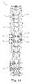
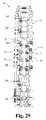
- FIG. 12shows the first adjustment assembly 32 from an isometric view
- FIG. 13shows the adjustment 32 assembly from a cross-sectional view
- FIG. 14shows the adjustment assembly 32 from a plan view with a portion of the housing removed
- FIG. 15shows the adjustment assembly 32 from a plan view with the housing intact, according to some embodiments.
- the first adjustment assembly 32is adapted to adjust, and provides means for adjusting tension and/or a distance between the first rod 12 and the first transverse anchor 28 .
- the first and second adjustment assemblies 32 , 34are optionally substantially similar. Thus, various features of both the first and second adjustment assemblies 32 , 34 are described in association with the first adjustment assembly 32 , where features of the first adjustment assembly 32 are designated with reference numbers and similar features of the second adjustment assembly 34 are designated with the same reference numbers followed by a “B.”
- the first adjustment assembly 32includes a tensioner 208 , the tensioner 208 including a housing 210 , a reel 212 , a circumferential gear 214 surrounding the reel 212 , a drive gear 216 in contact with the circumferential gear 214 , and an actuation head 218 .
- the first adjustment assembly 32also includes an elongate connector 219 adapted to be wound about the reel 212 .
- the reel 212as well as the circumferential gear 214 and drive gear 216 are maintained at least partially within the housing 210 .
- the housing 210is adapted to be secured to the first rod 12 .
- the housing 210optionally forms a central lumen 220 through which the rod first 12 is receivable. Upon inserting the first rod 12 through the central lumen 220 , the housing 210 is adapted to be clamped onto the first rod 12 .
- the housing 210defines a first side 223 and a second side 224 and incorporates a clamshell design (e.g., a first portion adjustably secured to a second portion) adapted to be tightened onto the first rod 12 (e.g., using one or more fasteners).
- a clamshell designe.g., a first portion adjustably secured to a second portion
- the first adjustment assembly 32is substantially fixed with respect to the first rod 12 .
- Other designs, such as monolithic housing designs and othersare contemplated.
- the first adjustment assembly 32is movable with respect to the first rod 12 , for example being able to slide and/or rotate about the first rod 12 .
- the central lumen 220 of the housing 210defines a longitudinal axis L and forms a pocket 226 for receiving the reel 212 and the circumferential gear 214 such that the reel 212 and the circumferential gear 214 are able to rotate within the housing 210 .
- the housing 210also defines a pair of opposed apertures 228 for receiving ends of the drive gear 216 to retain the drive gear 216 while allowing the drive gear 216 to rotate.
- the housing 210also defines a top 230 and a bottom 232 , where the bottom 232 forms a lower opening 234 and a raised abutment 236 adjacent to the lower opening 234 , toward the first side 223 of the housing 210 .
- the reel 212includes a helical groove 238 for receiving the elongate connector 219 and a raised anchor block 240 for securing the elongate connector 219 to the reel 212 .
- the anchor block 240optionally includes an aperture for receiving the elongate connector 219 and is welded or otherwise fastened in the aperture.
- the reel 212as well as the circumferential gear 214 , form a lumen 242 for coaxially receiving the first rod 12 .
- an overall size, or profile, of the tensioner 208is able to be reduced.
- the circumferential gear 214is connected to, and coaxially aligned with the reel 212 .
- the circumferential gear 214is engaged with the drive gear 216 such that rotation of the drive gear 216 causes the circumferential gear 214 , and thus, the reel 212 , to turn (e.g., in a worm or crossed-spur gear configuration).
- the elongate connector 219includes a flexible tether 250 and a connector head 252 .
- the flexible tether 250is substantially flexible and able to be pivoted in a multiple directions and/or be spooled or wound, for example.
- Suitable flexible materialsinclude wire and stranded cables, monofilament polymer materials, multifilament polymer materials, multifilament carbon or ceramic fibers, and others.
- the flexible tether 250is formed of cobalt chromium alloy or titanium alloy wire or cable, although a variety of materials are contemplated.
- the flexible tether 250includes a terminal cap 256 ( FIG. 16 ) adapted to be secured in the connector head 252 .
- the terminal cap 256has a rounded (e.g., semi-circular) head and is optionally swaged onto the flexible tether 250 . In other embodiments, rather than a swage a loop or other feature is implemented to connect of the connector head 252 .
- FIG. 16is a cross-sectional view of the connector head 252 , according to some embodiments.
- the connector head 252defines an internal bore 260 and forms a collar 262 , a raised shoulder 264 , and a neck 266 .
- the internal bore 260has a rounded seat 270 (e.g., a substantially concave seat).
- the connector head 252also has a first end 272 and a second end 274 , the second end 274 having a rounded inner profile 276 (like the horn of a trumpet).
- the flexible tether 250is secured to the connector head 252 by receiving the terminal cap 256 in the rounded seat 270 in a complementary fit.
- the elongate connector 219also described as a connector or cable, is adapted to be secured to the first transverse anchor 28 and the first adjustment assembly 32 . So secured, the elongate connector 219 defines an effective length between the first transverse anchor 28 and tensioner 208 and, and thus the first rod 12 (although, in some embodiments, the elongate connector 219 is secured directly to the rod 12 ). As described, in some embodiments, the tensioner 208 is adapted to modify, and provides means for modifying, the effective length of the tether 250 of the elongate connector 219 (e.g., by spooling the tether 250 on and off of the reel 212 ).
- the elongate connector 219is attached or secured to the reel 212 and passes out of the housing 210 through the lower opening 234 in the housing 210 .
- a lower openingis shown, in other embodiments the opening is in the side or top, for example.
- Actuation of the drive gear 216 via the actuation head 218turns the circumferential gear 214 , which turns the reel 212 , thus winding (or unwinding, depending on the direction in which the reel 212 is turned) the elongate connector 219 about the reel 212 .
- Rotation of the reel 212 in the appropriate directiondraws the tether 250 in toward the tensioner 208 ( FIG. 17 ), pulling the first transverse anchor 28 toward the tensioner 208 , according to some methods of correcting a spinal defect.
- FIG. 17shows the first actuation assembly 32 as it would appear in a first, extended state attached to the uncorrected spinal column 40 (e.g., FIG. 18 ) and as it would appear in a second, retracted state as attached to the corrected spinal column (e.g., FIG. 19 ), according to some embodiments.
- the connector head 252engages the raised abutment 236 and the housing 210 as the tether 250 is drawn into the housing 210 .
- This engagement and/or the orientation of the lower opening 234i.e., with the tether 250 exiting the housing 210 through the bottom helps generate a moment M on the first transverse anchor 28 (not shown in FIG.
- the ability of the tether 250 to flex and bend at the second end 274 of the connector head 252helps generate a polyaxial connection at the second end 274 and facilitates generation of the moment M as described.
- FIG. 18shows the assembled system 10 .
- assembly of the system 10 and associated methods of correcting the spine 40include securing the stabilizing anchors 16 , 18 to inferior and superior portions of the spine 40 .
- the first stabilizing anchor 16is optionally secured to the spine 40 by driving one of the plurality of fasteners 36 through each of the through holes 74 and into one or more of the vertebrae 42 .
- the first stabilizing anchor 16is secured with one of the fasteners 36 driven into a pedicle of the first vertebra 42 A and another of the fasteners 26 driven into a pedicle of another vertebra that is adjacent to the first vertebra 42 A.
- the second stabilizing anchor 18is similarly secured to the second vertebra 42 B and a vertebra adjacent the second vertebra 42 B.
- each of the first and second stabilizing anchorsis secured on the first side 40 A of the spine.
- the first and second actuation assemblies 32 , 34are slid onto or otherwise coupled to the first rod 12 and then secured (e.g., clamped) at a desired location along the rod 12 .
- the first rod 12is received in the first and second stabilizing anchors 16 , 18 , with the splined, or inferior portion 54 of the first rod 12 slidably received in the sleeve insert 82 of the first stabilizing anchor 16 and the superior portion 50 of the rod 12 slidably received in the second stabilizing anchor 18 .
- the first rod 12extends along the first side 40 A of the spine 40 and is secured against lateral movement relative to a portion of the spine 40 .
- the first rod 12is attached by the stabilizing anchors 16 , 18 to pedicles and/or transverse processes on the first side 40 A of the spinal column 40 and is able to slide axially relative to the first and/or second stabilizing anchors 16 , 18 .
- the rod 12is attached by the stabilizing anchors 16 , 18 to the second side 40 B of the spinal column 40 , on different sides of the spinal column 40 (e.g., the first stabilizing anchor 16 on the left side and the second stabilizing anchor 18 on the right side), or along the mid-line of the spinal column 40 .
- the first rod 12is adjustable length to compensate for changes in length of the spinal column 40 .
- the bend in the first rod 12is oriented and maintained in a desired rotational position. Maintaining the rotational orientation at one end (i.e., at the first stabilizing anchor 16 ) is useful, for example, to help ensure that the bend or shape of the rod 12 consistently follows or otherwise appropriately tracks a desired curvature of a spinal column 40 . Freedom of rotation at the other end of the first rod 12 (i.e., at the second stabilizing anchor 18 ), however, still permits the spinal column 40 to have more natural movement while the corrective forces are being applied.
- the system 10optionally includes one or more stop features for limiting axial sliding, or translation of the first rod 12 relative to one of the stabilizing anchors to a desired range.
- sliding of the first rod 12 in a particular axial directionis substantially limited, or arrested, when a stop feature engages, or abuts an adjacent stabilizing anchor 16 , though other stop mechanisms are contemplated.
- the first and second transverse anchors 28 , 30are secured to one or more of the vertebrae 42 , such as a third vertebra 42 C in an apical region A of the spine 40 and a fourth vertebra 42 D in an apical region A of the spine 40 .
- the first transverse anchor 28is secured to the third vertebra 42 C by driving one of the fasteners 36 through the slot 184 in the mounting portion 170 of the first transverse anchor 28 .
- the first transverse anchor 28is optionally secured into a pedicle and/or transverse processes of the third vertebra 42 C on the second side 40 B of the spine 40 .
- the second transverse anchor 30is optionally similarly secured on the second side of the spine 42 B to a pedicle of the fourth vertebra 42 D.
- the arm portions 176 , 176 B ( FIG. 11 ) of the first and second transverse anchors 28 , 30extend from the second side 40 B of the spine 40 to the first side 40 A of the spine 40 .
- the first and second actuation assemblies 32 , 34are secured to the first and second transverse anchors 28 , 30 by attaching (e.g., screwing) the connector heads 252 , 252 B of the elongate connectors 219 , 219 B to the threaded terminal sections of the transverse anchors 28 , 30 .
- Some methodsinclude adjusting a curvature of the spine 40 to a desired curvature using the actuation assemblies 32 , 34 .
- the tensioners 208 , 208 B of the first and second actuation assemblies 32 , 34are actuated (independently or simultaneously) in order to draw the elongate connectors 219 , 219 B into the respective tensioners 208 , 208 B, thereby drawing the third and fourth vertebrae 42 C, 42 D and surrounding portions of the spine 40 toward the first rod 12 and to a more desirable spinal curvature.
- first and third anchors 20 , 24are secured to a fifth vertebra 42 E and the second and fourth anchors 22 , 26 are secured to a sixth vertebrae 42 E, 42 F of the spine 40 , thought each of the connectors is optionally secured to a different vertebra.
- the first anchor 20is secured along the spine 40 at a location between the first stabilizing anchor 16 and the first actuation assembly 32 and the second stabilizing anchor 18 is secured at a location between the second stabilizing anchor 18 and the second actuation assembly 34 .
- the first and second anchors 20 , 22are secured on the first side 40 A of the spine 40 whereas the third and fourth anchors 24 , 26 are secured on the second side 40 B of the spine 40 opposite the first and second anchors 20 , 22 , for example.
- the first anchor 20is secured to a pedicle of the fifth vertebra 42 E by driving one of the fasteners 36 into the pedicle through the slot 154 in the mounting portion 140 of the first anchor 20 (FIG.
- the second, third, and fourth anchors 22 , 24 , 26are optionally similarly secured to the spine 40 .
- the first rod 12is received in the first and second anchors 20 , 22 (e.g., prior to securing the first and second anchors 20 , 22 to the spine 40 ) and the first rod 12 is secured in the pocket 164 of the first anchor 20 using the clamping screw 166 ( FIG. 10 ).
- the first rod 12is similarly secured in the second anchor 22 , thereby immobilizing the first rod 12 between the first and second anchors 20 , 22 .
- the second rod 14is received in the transverse anchors 28 , 30 , and optionally in the third and fourth anchors 24 , 26 (e.g., prior to securing the third and fourth anchors 24 , 26 to the spine 40 ) in order to provide secondary stabilization to the corresponding region of the spine 40 .
- the second rod 12is secured in the pocket of the third anchor 24 using the clamping screw and in the pocket 194 of the first transverse anchor 28 using the clamping screw 196 ( FIG. 11 ).
- the second rod 14is similarly secured in the second transverse anchor 30 and the fourth anchor 26 , thereby immobilizing the second rod 14 between the third and fourth anchors 24 , 26 .
- the first and second rods 12 , 14are on opposite sides of the spine 40 , immobilizing a desired region of the spine 40 (e.g., as part of a spinal fusion process), such as an apical region A of the spine 40 .
- a desired region of the spine 40e.g., as part of a spinal fusion process
- bone cement, fillers, or other materialsare optionally employed with one or more vertebrae 42 to facilitate intervertebral fusion.
- the system 10is configured to avoid fusion of the spine 40 .
- the first and/or second rods 12 , 14are optionally substantially flexible such that the system 10 allows sufficient movement of the spine 40 to help avoid intervertebral fusion while still providing structural support during growth and remodeling of the spine 40 .
- the first rod 12is clipped, cut, broken, or otherwise portioned between the first anchor 20 and the first stabilizing anchor 16 and between the second anchor 22 and the second stabilizing anchor 18 .
- the superior and inferior portions of the first rod 12are optionally removed from the first and second stabilizing anchors 16 , 18 and the first and second stabilizing anchors 16 , 18 are removed from the spine 40 .
- the first rod 12is not portioned and is left free to move in the stabilizing anchors 16 , 18 , for example.
- the entire system 10is optionally removed after a desired amount of fusion of the spine has been achieved and/or after sufficient growth and remodeling of the spinal curvature has been achieved. For example, once a diseased area of the spine has sufficiently healed (e.g., after being fused and stabilized) the stability provided by the system 10 may no longer be required.
- the spinal column 40(and thus, the person) is able to twist, bend side-to-side, and bend forward-and-backward in a more natural manner while corrective forces are being applied to the spinal column 40 and/or to achieve a desired correction of the spine 40 .
- the effective lengths of the actuation assemblies 34 , 36 , and specifically the elongate connectors 219 , 219 Bare adjusted (e.g., periodically or all at one time), bringing the spinal column into natural alignment, while the system 10 facilitates a more natural movement of the spinal column 40 (e.g., twisting and bending forward-and-backward and side-to-side) due to the freedom of movement afforded by the system 10 .
- the second rod 14is secured to the corrected spine 40 opposite first rod 12 to rigidly secure a region of the spine for fusion as shown in FIG. 23 .
- thisincludes immobilizing an apical region A of the spine 40 and leaving a superior region of the spine 40 adjacent to the apical region A and an inferior region of the spine 40 adjacent to the apical region A free to move in at least one degree of freedom.
- the at least one degree of freedomoptionally includes elongation, or growth, compression, twisting, and/or flexing.
- the freedom of movement of the first rod 12 provided by the stabilizing anchors 16 , 18helps facilitate this motion.
- removal of one or more portions of the system 10facilitates this motion.
- the lateral connection between the rods 12 , 14optionally helps resist vertebral rotation and lateral translation).
- the spine 40is optionally corrected, or tensioned toward the first rod 12 prior to securing the second rod 14 to the spine 40 .
- the corrective methodincludes securing the second rod 14 to the spine 40 (e.g., to partially or fully correct spinal curvature the apical region A) and then tensioning the second rod 14 toward the first rod 12 in order to correct the spine 40 or portions thereof (e.g., a curvature of the spine 40 superior and/or inferior to the apical region A).
- the system 10may include greater or fewer components according to various embodiments.
- FIG. 24is an example of the system 10 , which includes correction and secondary stabilization features, the system 10 including fewer components.
- the system 10is optionally used to correct a spinal deformity (including a total or partial correction) and then the second rod 14 is received in, and secured in, the pockets 194 , 194 B of the first and second transverse anchors 28 , 30 .
- the secondary stabilization provided by the second rod 14is optionally used to facilitate fusion of the spine 40 , including use of growth promoters or other materials for encouraging intervertebral fusion.
- FIG. 25shows another stabilizing anchor 16 A (also described as a rod anchor) of the system 10 , according to some embodiments.
- the first stabilizing anchor 16 Ais adapted, or otherwise structured, to be mounted, or fixed to one or more of the vertebrae 42 , such as a first vertebra 42 A ( FIG. 1 ) located at an inferior position, or other position, along the spine 40 .
- the first stabilizing anchor 16 Ais substantially similar to the first stabilizing anchor 16 .
- the first stabilizing anchor 16 Aincludes a mounting portion 70 A and a housing portion 72 A.
- the mounting portion 70 Aoptionally includes through holes 74 A for receiving one of the fasteners 36 , such as a pedicle screw or similar device to secure the mounting portion 70 A to one or more vertebrae 42 , such as the first vertebra 42 A.
- the housing portion 72 A of the first stabilizing anchor 16 Aincludes a body 80 A and a sleeve insert 82 A.
- the body 80 Ais substantially similar to the body 80 of the first stabilizing anchor 16 with an optional difference being that the body 80 A is split by a gap 298 A dividing the body 80 A into a lower portion 300 A and an upper portion 302 A that can be clamped together with adjustment member 304 A (e.g., a bolt) secured across the gap 298 A.
- adjustment member 304 Ae.g., a bolt
- the sleeve insert 82 Ais substantially similar to the sleeve insert 82 with the addition of a gap 306 A that facilitates clamping of the sleeve insert 82 A onto the rod 12 .
- the sleeve insert 82 Ais clamped onto rod 12 to arrest sliding and rolling motion of the rod 12 through the sleeve insert 82 A. Additionally, the clamping action of the body 80 A on the sleeve 82 A arrests changes in pitch and yaw. In different terms, the rod 12 is able to be selectively locked relative to the stabilizing anchor 16 A.
- FIG. 26shows another stabilizing anchor 16 B (also described as a rod anchor) of the system 10 , according to some embodiments.
- the first stabilizing anchor 16 Bis adapted, or otherwise structured, to be mounted, or fixed to one or more of the vertebrae 42 , such as a first vertebra 42 A ( FIG. 1 ) located at an inferior position, or other position, along the spine 40 .
- the first stabilizing anchor 16 Bis substantially similar to the first stabilizing anchors 16 , 16 A and includes a clamping mechanism similar to first stabilizing anchor 16 A.
- the first stabilizing anchor 16 Bincludes a mounting portion 70 B and a housing portion 72 B.
- the mounting portion 70 Bdiffers from the mounting portion 70 A of the first stabilizing anchor 16 A in that the mounting 70 B portion includes a single through hole 74 A for receiving one of the fasteners 36 , such as a pedicle screw or similar device to secure the mounting portion 70 B to one or more vertebrae 42 , such as the first vertebra 42 A.
- the first stabilizing anchor 16 Bis adapted to be secured to a single vertebra, as compared to being secured across multiple vertebrae.
- FIG. 27shows the system 10 employing the first stabilizing anchor 16 A and a second stabilizing anchor 18 A that is substantially the same as the first stabilizing anchor 16 A, according to some embodiments.
- the rod 12 of the system 10is able to slide and change in pitch, yaw, and roll at both of the anchors 16 A, 18 A and is also able to be selectively locked against sliding, pitch, yaw, and roll at each of the first and second stabilizing anchors 16 A, 18 A.
- Selective locking at one or both anchors 16 A, 18 Ais optionally employed for a variety of reasons, including for performing partial or total fusion, to facilitate a correction, or adjustment process using the tensioners 32 , 34 , or to facilitate assembly of the system 10 prior to a correction operation.
- FIG. 28shows the system 10 employing the first and second stabilizing anchors 16 A, 18 A similarly to FIG. 27 , according to some embodiments.
- the first anchor 20 and the second anchor 22 shown in FIG. 27are replaced by first and second anchors 20 B, 22 B, which are each substantially the same as the first stabilizing anchor 16 B ( FIG. 26 ).
- the rod 12 of the system 10is able to slide and change pitch, yaw and roll at the anchors 16 A, 18 A, 20 B, 22 B and is also able to be selectively locked against sliding, pitch, yaw, and roll at each of the anchors 16 A, 18 A, 20 B, 22 B as desired.
- selective locking at any of the anchors 16 A, 18 A, 20 B, 22 Bis optionally employed for a variety of reasons, including for performing partial or total fusion, to facilitate a correction, or adjustment process using the tensioners 32 , 34 , or to facilitate assembly of the system 10 prior to a correction operation.
- FIG. 29shows the system 10 employing a plurality of anchors, each of which is substantially similar to the first stabilizing anchor 16 B ( FIG. 26 ).
- the rod 12 of the system 10is able to slide and change in pitch, yaw and roll at the anchors 16 B, 18 B, 20 B, 22 B.
- the first anchor 16 Boptionally employs a chase feature similar to those previously described to limit roll.
- the first anchor 16 Bfreely permits roll of the rod 12 .
- the rod 12has a high degree of freedom, while being laterally constrained, as desired.
- the rod 12is also able to be selectively locked against sliding, pitch, yaw, and roll at each of the anchors 16 B, 18 B, 20 B, 22 B as desired.
- selective locking at any of the anchorsis optionally employed for a variety of reasons, including for performing partial or total fusion, to facilitate a correction, or adjustment process using the tensioners 32 , 34 , or to facilitate assembly of the system 10 prior to a correction operation. From the foregoing, it should be understood that a variety of numbers and configurations of the anchors is contemplated. Though not specifically shown, it should also be understood that any of the foregoing anchors are employed with the second rod 14 on the second side of the spine.
Landscapes
- Health & Medical Sciences (AREA)
- Orthopedic Medicine & Surgery (AREA)
- Life Sciences & Earth Sciences (AREA)
- Surgery (AREA)
- Neurology (AREA)
- Heart & Thoracic Surgery (AREA)
- Engineering & Computer Science (AREA)
- Biomedical Technology (AREA)
- Nuclear Medicine, Radiotherapy & Molecular Imaging (AREA)
- Medical Informatics (AREA)
- Molecular Biology (AREA)
- Animal Behavior & Ethology (AREA)
- General Health & Medical Sciences (AREA)
- Public Health (AREA)
- Veterinary Medicine (AREA)
- Surgical Instruments (AREA)
- Prostheses (AREA)
Abstract
Description
Claims (19)
Priority Applications (3)
| Application Number | Priority Date | Filing Date | Title |
|---|---|---|---|
| US14/482,927US9113959B2 (en) | 2011-11-16 | 2014-09-10 | Spinal correction and secondary stabilization |
| US14/814,728US9827017B2 (en) | 2011-11-16 | 2015-07-31 | Spinal correction and secondary stabilization |
| US15/795,827US10702311B2 (en) | 2011-11-16 | 2017-10-27 | Spinal correction and secondary stabilization |
Applications Claiming Priority (4)
| Application Number | Priority Date | Filing Date | Title |
|---|---|---|---|
| US13/297,841US20130123853A1 (en) | 2011-11-16 | 2011-11-16 | Spinal correction and secondary stabilization |
| US13/865,775US8920472B2 (en) | 2011-11-16 | 2013-04-18 | Spinal correction and secondary stabilization |
| US14/029,610US9468469B2 (en) | 2011-11-16 | 2013-09-17 | Transverse coupler adjuster spinal correction systems and methods |
| US14/482,927US9113959B2 (en) | 2011-11-16 | 2014-09-10 | Spinal correction and secondary stabilization |
Related Parent Applications (1)
| Application Number | Title | Priority Date | Filing Date |
|---|---|---|---|
| US13/865,775DivisionUS8920472B2 (en) | 2011-11-16 | 2013-04-18 | Spinal correction and secondary stabilization |
Related Child Applications (1)
| Application Number | Title | Priority Date | Filing Date |
|---|---|---|---|
| US14/814,728ContinuationUS9827017B2 (en) | 2011-11-16 | 2015-07-31 | Spinal correction and secondary stabilization |
Publications (2)
| Publication Number | Publication Date |
|---|---|
| US20140379035A1 US20140379035A1 (en) | 2014-12-25 |
| US9113959B2true US9113959B2 (en) | 2015-08-25 |
Family
ID=56291312
Family Applications (3)
| Application Number | Title | Priority Date | Filing Date |
|---|---|---|---|
| US13/865,775ActiveUS8920472B2 (en) | 2011-11-16 | 2013-04-18 | Spinal correction and secondary stabilization |
| US14/482,927ActiveUS9113959B2 (en) | 2011-11-16 | 2014-09-10 | Spinal correction and secondary stabilization |
| US14/814,728Expired - Fee RelatedUS9827017B2 (en) | 2011-11-16 | 2015-07-31 | Spinal correction and secondary stabilization |
Family Applications Before (1)
| Application Number | Title | Priority Date | Filing Date |
|---|---|---|---|
| US13/865,775ActiveUS8920472B2 (en) | 2011-11-16 | 2013-04-18 | Spinal correction and secondary stabilization |
Family Applications After (1)
| Application Number | Title | Priority Date | Filing Date |
|---|---|---|---|
| US14/814,728Expired - Fee RelatedUS9827017B2 (en) | 2011-11-16 | 2015-07-31 | Spinal correction and secondary stabilization |
Country Status (1)
| Country | Link |
|---|---|
| US (3) | US8920472B2 (en) |
Cited By (4)
| Publication number | Priority date | Publication date | Assignee | Title |
|---|---|---|---|---|
| US9827017B2 (en) | 2011-11-16 | 2017-11-28 | K2M, Inc. | Spinal correction and secondary stabilization |
| US9827022B2 (en)* | 2009-09-15 | 2017-11-28 | K2M, Llc | Growth modulation system |
| US10342581B2 (en) | 2011-11-16 | 2019-07-09 | K2M, Inc. | System and method for spinal correction |
| US10702311B2 (en) | 2011-11-16 | 2020-07-07 | K2M, Inc. | Spinal correction and secondary stabilization |
Families Citing this family (15)
| Publication number | Priority date | Publication date | Assignee | Title |
|---|---|---|---|---|
| US8114158B2 (en) | 2004-08-03 | 2012-02-14 | Kspine, Inc. | Facet device and method |
| US8828058B2 (en) | 2008-11-11 | 2014-09-09 | Kspine, Inc. | Growth directed vertebral fixation system with distractible connector(s) and apical control |
| US8357182B2 (en) | 2009-03-26 | 2013-01-22 | Kspine, Inc. | Alignment system with longitudinal support features |
| JP6158176B2 (en) | 2011-06-03 | 2017-07-05 | ケイツーエム インコーポレイテッドK2M,Inc. | Spine correction system |
| US9468468B2 (en) | 2011-11-16 | 2016-10-18 | K2M, Inc. | Transverse connector for spinal stabilization system |
| US9468469B2 (en) | 2011-11-16 | 2016-10-18 | K2M, Inc. | Transverse coupler adjuster spinal correction systems and methods |
| US10687860B2 (en)* | 2012-04-24 | 2020-06-23 | Retrospine Pty Ltd | Segmental correction of lumbar lordosis |
| US9968379B2 (en) | 2012-10-04 | 2018-05-15 | Loubert S. Suddaby | Subcutaneous implantable device for gradually aligning a spine and subcutaneous implantable device for gradually lengthening a bone |
| US9468471B2 (en) | 2013-09-17 | 2016-10-18 | K2M, Inc. | Transverse coupler adjuster spinal correction systems and methods |
| CA3223705A1 (en) | 2014-06-25 | 2015-12-30 | Canary Medical Switzerland Ag | Devices, systems and methods for using and monitoring spinal implants |
| EP3160331A4 (en) | 2014-06-25 | 2018-09-12 | Canary Medical Inc. | Devices, systems and methods for using and monitoring orthopedic hardware |
| CA2998709A1 (en) | 2014-09-17 | 2016-03-24 | Canary Medical Inc. | Devices, systems and methods for using and monitoring medical devices |
| EP3085319B1 (en)* | 2015-04-21 | 2017-10-11 | Biedermann Technologies GmbH & Co. KG | Template for use in manufacturing an implant for spinal or other orthopaedic fixation and method of manufacturing such a template |
| WO2017142426A1 (en)* | 2016-02-19 | 2017-08-24 | Gallagher Group Limited | A fence post |
| US10188428B2 (en)* | 2017-05-15 | 2019-01-29 | Loubert S. Suddaby | Subcutaneous implantable device for gradually aligning a spine |
Citations (454)
| Publication number | Priority date | Publication date | Assignee | Title |
|---|---|---|---|---|
| US2774350A (en) | 1952-09-08 | 1956-12-18 | Jr Carl S Cleveland | Spinal clamp or splint |
| US3242922A (en) | 1963-06-25 | 1966-03-29 | Charles B Thomas | Internal spinal fixation means |
| US3352226A (en) | 1965-03-15 | 1967-11-14 | Silas E Nelsen | Infusion package |
| US3648691A (en) | 1970-02-24 | 1972-03-14 | Univ Colorado State Res Found | Method of applying vertebral appliance |
| US3693616A (en) | 1970-06-26 | 1972-09-26 | Robert Roaf | Device for correcting scoliotic curves |
| US3865105A (en) | 1973-05-16 | 1975-02-11 | Lode S Instr N V | Device for exerting forces on and fixing the spinal column of a human body |
| DE2644735A1 (en) | 1975-05-30 | 1977-04-07 | Erkki Einari Dipl Ing Nissinen | STRETCH AND SUPPORT DEVICE FOR THE SPINAL COLUMN |
| US4024588A (en) | 1974-10-04 | 1977-05-24 | Allo Pro A.G. | Artificial joints with magnetic attraction or repulsion |
| DE2845647A1 (en) | 1978-10-20 | 1980-05-08 | Messerschmitt Boelkow Blohm | Implanted surgical device for correcting spinal curvature - has correction rod rotated by motor to gradually shorten wire attached to spine |
| US4257409A (en) | 1978-04-14 | 1981-03-24 | Kazimierz Bacal | Device for treatment of spinal curvature |
| US4269178A (en) | 1979-06-04 | 1981-05-26 | Keene James S | Hook assembly for engaging a spinal column |
| US4274401A (en) | 1978-12-08 | 1981-06-23 | Miskew Don B W | Apparatus for correcting spinal deformities and method for using |
| SU888968A1 (en) | 1979-01-11 | 1981-12-15 | Новосибирский научно-исследовательский институт травматологии и ортопедии | Apparatus for correcting vertebral column |
| US4355645A (en) | 1978-10-18 | 1982-10-26 | Kabushiki Kaisha Morita Seisakusho | Device for displaying masticatory muscle activities |
| US4361141A (en) | 1979-07-27 | 1982-11-30 | Zimmer Usa, Inc. | Scoliosis transverse traction assembly |
| US4369769A (en) | 1980-06-13 | 1983-01-25 | Edwards Charles C | Spinal fixation device and method |
| US4404967A (en) | 1982-01-18 | 1983-09-20 | Wyzsza Szkola Inzynierska Im. Jurija Gagarina | Surgical strut for treatment of the back-bone |
| US4411259A (en) | 1980-02-04 | 1983-10-25 | Drummond Denis S | Apparatus for engaging a hook assembly to a spinal column |
| US4411545A (en) | 1981-03-06 | 1983-10-25 | Skf Compagnie D'applications Mecaniques - Adr | Swivel joint |
| US4448191A (en) | 1981-07-07 | 1984-05-15 | Rodnyansky Lazar I | Implantable correctant of a spinal curvature and a method for treatment of a spinal curvature |
| US4505268A (en) | 1983-02-17 | 1985-03-19 | Vicente Sgandurra | Scoliosis frame |
| US4554914A (en) | 1983-10-04 | 1985-11-26 | Kapp John P | Prosthetic vertebral body |
| US4573454A (en) | 1984-05-17 | 1986-03-04 | Hoffman Gregory A | Spinal fixation apparatus |
| US4604995A (en) | 1984-03-30 | 1986-08-12 | Stephens David C | Spinal stabilizer |
| US4611581A (en) | 1983-12-16 | 1986-09-16 | Acromed Corporation | Apparatus for straightening spinal columns |
| US4611582A (en) | 1983-12-27 | 1986-09-16 | Wisconsin Alumni Research Foundation | Vertebral clamp |
| US4634445A (en) | 1981-01-30 | 1987-01-06 | Oec Europe Limited | Joint prosthesis |
| US4648388A (en) | 1985-11-01 | 1987-03-10 | Acromed Corporation | Apparatus and method for maintaining vertebrae in a desired relationship |
| US4653481A (en) | 1985-07-24 | 1987-03-31 | Howland Robert S | Advanced spine fixation system and method |
| US4658809A (en) | 1983-02-25 | 1987-04-21 | Firma Heinrich C. Ulrich | Implantable spinal distraction splint |
| US4697582A (en) | 1983-10-28 | 1987-10-06 | Peze William | Appliance for correcting rachidial deformities |
| US4738251A (en) | 1987-02-20 | 1988-04-19 | Codespi, Corporation | Correcting device for spine pathology |
| US4773402A (en) | 1985-09-13 | 1988-09-27 | Isola Implants, Inc. | Dorsal transacral surgical implant |
| US4805602A (en) | 1986-11-03 | 1989-02-21 | Danninger Medical Technology | Transpedicular screw and rod system |
| US4815453A (en) | 1983-05-04 | 1989-03-28 | Societe De Fabrication De Materiel Orthopedique (Sofamor) | Device for supporting the rachis |
| US4827918A (en) | 1985-08-15 | 1989-05-09 | Sven Olerud | Fixing instrument for use in spinal surgery |
| US4854311A (en) | 1986-01-09 | 1989-08-08 | Acro Med Corporation | Bone screw |
| US4931055A (en) | 1986-05-30 | 1990-06-05 | John Bumpus | Distraction rods |
| US4936848A (en) | 1989-09-22 | 1990-06-26 | Bagby George W | Implant for vertebrae |
| US5000166A (en) | 1988-04-27 | 1991-03-19 | Sulzer Brothers Limited | Implant kit for stabilizing regions of a spine |
| EP0418387A1 (en) | 1989-02-21 | 1991-03-27 | Vsesojuzny Kurgansky Nauchny Tsentr "Vosstanovitelnaya Travmatologia I Ortopedia" | Device for treatment of curvature of and damage to the spine |
| US5005562A (en) | 1988-06-24 | 1991-04-09 | Societe De Fabrication De Material Orthopedique | Implant for spinal osteosynthesis device, in particular in traumatology |
| US5011484A (en) | 1987-11-16 | 1991-04-30 | Breard Francis H | Surgical implant for restricting the relative movement of vertebrae |
| EP0260044B1 (en) | 1986-08-29 | 1991-05-22 | John Anthony Norman Shepperd | Spinal implant |
| US5030220A (en) | 1990-03-29 | 1991-07-09 | Advanced Spine Fixation Systems Incorporated | Spine fixation system |
| US5042982A (en) | 1987-07-08 | 1991-08-27 | Harms Juergen | Positioning device |
| US5084049A (en) | 1989-02-08 | 1992-01-28 | Acromed Corporation | Transverse connector for spinal column corrective devices |
| EP0322334B1 (en) | 1987-12-23 | 1992-02-26 | Cremascoli France | Prosthesis implanted between vertebral spinous processes |
| US5092867A (en) | 1988-07-13 | 1992-03-03 | Harms Juergen | Correction and supporting apparatus, in particular for the spinal column |
| US5092866A (en) | 1989-02-03 | 1992-03-03 | Breard Francis H | Flexible inter-vertebral stabilizer as well as process and apparatus for determining or verifying its tension before installation on the spinal column |
| US5127912A (en) | 1990-10-05 | 1992-07-07 | R. Charles Ray | Sacral implant system |
| US5129900A (en) | 1990-07-24 | 1992-07-14 | Acromed Corporation | Spinal column retaining method and apparatus |
| US5133716A (en) | 1990-11-07 | 1992-07-28 | Codespi Corporation | Device for correction of spinal deformities |
| WO1992013496A1 (en) | 1991-02-01 | 1992-08-20 | Biostab | Frame for rigidifying a bone or a bone assembly |
| US5147363A (en) | 1989-12-21 | 1992-09-15 | Haerle Anton | Screw for use in osteosynthesis |
| US5176680A (en) | 1990-02-08 | 1993-01-05 | Vignaud Jean Louis | Device for the adjustable fixing of spinal osteosynthesis rods |
| US5176679A (en) | 1991-09-23 | 1993-01-05 | Lin Chih I | Vertebral locking and retrieving system |
| US5181917A (en) | 1990-06-19 | 1993-01-26 | Chaim Rogozinski | System and method for instrumentation of the spine in the treatment of spinal deformities |
| US5190543A (en) | 1990-11-26 | 1993-03-02 | Synthes (U.S.A.) | Anchoring device |
| US5207678A (en) | 1989-07-20 | 1993-05-04 | Prufer | Pedicle screw and receiver member therefore |
| US5209752A (en) | 1991-12-04 | 1993-05-11 | Danek Medical, Inc. | Lateral offset connector for spinal implant system |
| US5219349A (en) | 1991-02-15 | 1993-06-15 | Howmedica, Inc. | Spinal fixator reduction frame |
| US5242443A (en) | 1991-08-15 | 1993-09-07 | Smith & Nephew Dyonics, Inc. | Percutaneous fixation of vertebrae |
| US5254118A (en) | 1991-12-04 | 1993-10-19 | Srdjian Mirkovic | Three dimensional spine fixation system |
| US5257994A (en) | 1991-09-23 | 1993-11-02 | Lin Chih I | Vertebral locking and retrieving system |
| US5259398A (en) | 1989-10-26 | 1993-11-09 | Giuseppe Vrespa | Method for fixing prosthesis to bones |
| US5282862A (en) | 1991-12-03 | 1994-02-01 | Artifex Ltd. | Spinal implant system and a method for installing the implant onto a vertebral column |
| US5306275A (en) | 1992-12-31 | 1994-04-26 | Bryan Donald W | Lumbar spine fixation apparatus and method |
| FR2697744A1 (en) | 1992-11-10 | 1994-05-13 | Fabrication Mat Orthopedique S | Spinal osteosynthesis instrumentation by the anterior route. |
| US5312410A (en) | 1992-12-07 | 1994-05-17 | Danek Medical, Inc. | Surgical cable tensioner |
| US5312420A (en) | 1992-10-09 | 1994-05-17 | United States Surgical Corporation | Surgical apparatus for removing fasteners |
| US5330473A (en) | 1993-03-04 | 1994-07-19 | Advanced Spine Fixation Systems, Inc. | Branch connector for spinal fixation systems |
| US5330474A (en) | 1991-09-23 | 1994-07-19 | Lin Chih I | Vertebral locking and retrieving system |
| US5352226A (en) | 1993-02-08 | 1994-10-04 | Lin Chih I | Side locking system rotatable in all directions for use in spinal surgery |
| US5360431A (en) | 1990-04-26 | 1994-11-01 | Cross Medical Products | Transpedicular screw system and method of use |
| US5366455A (en) | 1988-11-04 | 1994-11-22 | Surgicraft Limited | Pedicle engaging means |
| US5368594A (en) | 1991-09-30 | 1994-11-29 | Fixano S.A. | Vertebral osteosynthesis device |
| US5380323A (en) | 1993-06-16 | 1995-01-10 | Advanced Spine Fixation Systems, Inc. | Clamps for spinal fixation systems |
| US5380325A (en) | 1992-11-06 | 1995-01-10 | Biomat | Osteosynthesis device for spinal consolidation |
| US5382248A (en) | 1992-09-10 | 1995-01-17 | H. D. Medical, Inc. | System and method for stabilizing bone segments |
| US5387213A (en) | 1991-02-05 | 1995-02-07 | Safir S.A.R.L. | Osseous surgical implant particularly for an intervertebral stabilizer |
| US5387212A (en) | 1993-01-26 | 1995-02-07 | Yuan; Hansen A. | Vertebral locking and retrieving system with central locking rod |
| US5391168A (en) | 1992-04-01 | 1995-02-21 | Acromed B.V. | Device for correcting the shape of the human spinal column and/or for fixing the human spinal column |
| US5397363A (en) | 1992-08-11 | 1995-03-14 | Gelbard; Steven D. | Spinal stabilization implant system |
| US5413576A (en) | 1993-02-10 | 1995-05-09 | Rivard; Charles-Hilaire | Apparatus for treating spinal disorder |
| US5436542A (en) | 1994-01-28 | 1995-07-25 | Surgix, Inc. | Telescopic camera mount with remotely controlled positioning |
| US5437669A (en) | 1993-08-12 | 1995-08-01 | Amei Technologies Inc. | Spinal fixation systems with bifurcated connectors |
| US5437671A (en) | 1992-03-10 | 1995-08-01 | Zimmer, Inc. | Perpendicular rod connector for spinal fixation device |
| US5456722A (en) | 1993-01-06 | 1995-10-10 | Smith & Nephew Richards Inc. | Load bearing polymeric cable |
| US5466238A (en) | 1993-08-27 | 1995-11-14 | Lin; Chih-I | Vertebral locking and retrieving system having a fixation crossbar |
| US5470333A (en) | 1993-03-11 | 1995-11-28 | Danek Medical, Inc. | System for stabilizing the cervical and the lumbar region of the spine |
| US5480440A (en) | 1991-08-15 | 1996-01-02 | Smith & Nephew Richards, Inc. | Open surgical technique for vertebral fixation with subcutaneous fixators positioned between the skin and the lumbar fascia of a patient |
| US5486174A (en) | 1993-02-24 | 1996-01-23 | Soprane S.A. | Fastener for the osteosynthesis of the spinal column |
| US5487744A (en) | 1993-04-08 | 1996-01-30 | Advanced Spine Fixation Systems, Inc. | Closed connector for spinal fixation systems |
| US5490851A (en) | 1994-08-02 | 1996-02-13 | Nenov; Nikolay N. | Method and apparatus for treatment of idiopathic scoliosis |
| US5496318A (en) | 1993-01-08 | 1996-03-05 | Advanced Spine Fixation Systems, Inc. | Interspinous segmental spine fixation device |
| US5498262A (en) | 1992-12-31 | 1996-03-12 | Bryan; Donald W. | Spinal fixation apparatus and method |
| US5501684A (en) | 1992-06-25 | 1996-03-26 | Synthes (U.S.A.) | Osteosynthetic fixation device |
| US5520688A (en) | 1994-07-20 | 1996-05-28 | Lin; Chih-I | Vertebral auxiliary fixation device |
| US5527314A (en) | 1993-01-04 | 1996-06-18 | Danek Medical, Inc. | Spinal fixation system |
| US5540689A (en) | 1990-05-22 | 1996-07-30 | Sanders; Albert E. | Apparatus for securing a rod adjacent to a bone |
| US5544993A (en) | 1993-12-13 | 1996-08-13 | H+E,Uml A+Ee Rle; Anton | Threaded fastener |
| US5549679A (en) | 1994-05-20 | 1996-08-27 | Kuslich; Stephen D. | Expandable fabric implant for stabilizing the spinal motion segment |
| US5562660A (en) | 1993-02-09 | 1996-10-08 | Plus Endoprothetik Ag | Apparatus for stiffening and/or correcting the vertebral column |
| US5569246A (en) | 1993-12-28 | 1996-10-29 | Asahi Kogaku Kogyo Kabushiki Kaisha | Fixing instrument for spinal fusion members |
| US5571191A (en) | 1995-03-16 | 1996-11-05 | Fitz; William R. | Artificial facet joint |
| US5575791A (en) | 1994-07-27 | 1996-11-19 | Lin; Chih-I | Universal eccentric fixation mechanism for orthopedic surgery |
| US5584626A (en) | 1995-06-15 | 1996-12-17 | Excelsior Development Inc. | Torque-limiting fastening element |
| US5586983A (en) | 1990-05-22 | 1996-12-24 | Sanders; Albert E. | Bone clamp of shape memory material |
| US5591165A (en) | 1992-11-09 | 1997-01-07 | Sofamor, S.N.C. | Apparatus and method for spinal fixation and correction of spinal deformities |
| FR2736535A1 (en) | 1995-07-10 | 1997-01-17 | Martin Jean Jacques | Spinal osteosynthesis device to immobilise portion of spine e.g. in case of pathological degeneration between vertebrae |
| US5601554A (en) | 1993-03-04 | 1997-02-11 | Advanced Spine Fixation Systems, Inc. | Branch connector for spinal fixation systems |
| US5611800A (en) | 1994-02-15 | 1997-03-18 | Alphatec Manufacturing, Inc. | Spinal fixation system |
| US5620443A (en) | 1995-01-25 | 1997-04-15 | Danek Medical, Inc. | Anterior screw-rod connector |
| US5630816A (en) | 1995-05-01 | 1997-05-20 | Kambin; Parviz | Double barrel spinal fixation system and method |
| US5643259A (en) | 1994-03-31 | 1997-07-01 | Ricardo C. Sasso | Spine fixation instrumentation |
| US5645599A (en) | 1994-07-26 | 1997-07-08 | Fixano | Interspinal vertebral implant |
| US5649926A (en) | 1994-07-14 | 1997-07-22 | Advanced Spine Fixation Systems, Inc. | Spinal segmental reduction derotational fixation system |
| US5658284A (en) | 1994-06-30 | 1997-08-19 | Allo Pro Ag | Connection member for the connection of a resilient rod with a bone screw which can be anchored in a vertebra |
| US5672175A (en)* | 1993-08-27 | 1997-09-30 | Martin; Jean Raymond | Dynamic implanted spinal orthosis and operative procedure for fitting |
| US5676703A (en) | 1994-05-11 | 1997-10-14 | Gelbard; Steven D. | Spinal stabilization implant system |
| US5702399A (en) | 1996-05-16 | 1997-12-30 | Pioneer Laboratories, Inc. | Surgical cable screw connector |
| US5702452A (en) | 1995-01-23 | 1997-12-30 | Sofamor S.N.C. | Spinal osteosynthesis device with median hook and vertebral anchoring support |
| US5702395A (en) | 1992-11-10 | 1997-12-30 | Sofamor S.N.C. | Spine osteosynthesis instrumentation for an anterior approach |
| US5704936A (en) | 1992-04-10 | 1998-01-06 | Eurosurgical | Spinal osteosynthesis device |
| US5713898A (en) | 1993-05-18 | 1998-02-03 | Schafer Micomed Gmbh | Orthopedic surgical holding device |
| US5716355A (en) | 1995-04-10 | 1998-02-10 | Sofamor Danek Group, Inc. | Transverse connection for spinal rods |
| US5720746A (en) | 1994-11-16 | 1998-02-24 | Soubeiran; Arnaud Andre | Device for displacing two bodies relative to each other |
| US5725582A (en) | 1992-08-19 | 1998-03-10 | Surgicraft Limited | Surgical implants |
| US5728097A (en) | 1992-03-17 | 1998-03-17 | Sdgi Holding, Inc. | Method for subcutaneous suprafascial internal fixation |
| US5733284A (en) | 1993-08-27 | 1998-03-31 | Paulette Fairant | Device for anchoring spinal instrumentation on a vertebra |
| US5735852A (en) | 1995-05-22 | 1998-04-07 | Synthes (U.S.A.) | Clamp jaw for a spinal affixation device |
| US5782831A (en) | 1996-11-06 | 1998-07-21 | Sdgi Holdings, Inc. | Method an device for spinal deformity reduction using a cable and a cable tensioning system |
| US5797910A (en) | 1993-08-27 | 1998-08-25 | Paulette Fairant | Operative equipment for correcting a spinal deformity |
| US5810819A (en) | 1997-05-15 | 1998-09-22 | Spinal Concepts, Inc. | Polyaxial pedicle screw having a compression locking rod gripping mechanism |
| US5810817A (en) | 1992-06-19 | 1998-09-22 | Roussouly; Pierre | Spinal therapy apparatus |
| US5814046A (en) | 1992-11-13 | 1998-09-29 | Sofamor S.N.C. | Pedicular screw and posterior spinal instrumentation |
| US5885285A (en) | 1995-08-14 | 1999-03-23 | Simonson; Peter Melott | Spinal implant connection assembly |
| US5891145A (en) | 1997-07-14 | 1999-04-06 | Sdgi Holdings, Inc. | Multi-axial screw |
| US5902305A (en) | 1996-07-11 | 1999-05-11 | Aesculap Ag & Co. Kg | Surgical tensioning device |
| US5910142A (en) | 1998-10-19 | 1999-06-08 | Bones Consulting, Llc | Polyaxial pedicle screw having a rod clamping split ferrule coupling element |
| US5928232A (en) | 1994-11-16 | 1999-07-27 | Advanced Spine Fixation Systems, Incorporated | Spinal fixation system |
| US5938663A (en) | 1995-03-06 | 1999-08-17 | Stryker France, S.A. | Spinal instruments, particularly for a rod |
| US5947967A (en) | 1997-10-22 | 1999-09-07 | Sdgt Holdings, Inc. | Variable angle connector |
| US5964769A (en) | 1997-08-26 | 1999-10-12 | Spinal Concepts, Inc. | Surgical cable system and method |
| US5976135A (en) | 1997-12-18 | 1999-11-02 | Sdgi Holdings, Inc. | Lateral connector assembly |
| US5980521A (en) | 1995-03-30 | 1999-11-09 | Sdgi Holdings,Inc. | Top-tightening transverse connector for a spinal fixation system |
| US5984924A (en) | 1998-10-07 | 1999-11-16 | Isola Implants, Inc. | Bone alignment system having variable orientation bone anchors |
| US5989256A (en) | 1999-01-19 | 1999-11-23 | Spineology, Inc. | Bone fixation cable ferrule |
| US6015409A (en) | 1994-05-25 | 2000-01-18 | Sdgi Holdings, Inc. | Apparatus and method for spinal fixation and correction of spinal deformities |
| FR2781359A1 (en) | 1998-07-21 | 2000-01-28 | Pierre Boccara | Osteosynthesis frame for spinal surgery has rod with clamps to hold cross bars with anchor screws |
| US6033412A (en) | 1997-04-03 | 2000-03-07 | Losken; H. Wolfgang | Automated implantable bone distractor for incremental bone adjustment |
| US6039738A (en) | 1997-07-03 | 2000-03-21 | Depuy Orthopaedics, Inc. | Fastener |
| US6053921A (en) | 1997-08-26 | 2000-04-25 | Spinal Concepts, Inc. | Surgical cable system and method |
| US6077268A (en) | 1994-03-29 | 2000-06-20 | Sdgi Holdings, Inc. | Variable angle surgical cable crimp assembly and method |
| US6086590A (en) | 1999-02-02 | 2000-07-11 | Pioneer Laboratories, Inc. | Cable connector for orthopaedic rod |
| US6101678A (en) | 1998-11-13 | 2000-08-15 | Invacare Corporation | Adjustable handle for a manually movable vehicle |
| US6110173A (en) | 1998-09-15 | 2000-08-29 | Advanced Spine Fixation Systems, Inc. | Transverse connector for spinal fixation systems |
| US6123706A (en) | 1997-12-17 | 2000-09-26 | Lange; Robert | Apparatus for stabilizing certain vertebrae of the spine |
| US6132464A (en) | 1994-06-24 | 2000-10-17 | Paulette Fairant | Vertebral joint facets prostheses |
| US6132431A (en) | 1996-04-18 | 2000-10-17 | Tresona Instrument Ab | Device and method for correcting and stabilizing a deviating curvature of a spinal column |
| US6136000A (en) | 1996-01-19 | 2000-10-24 | Louis; Rene | Anchoring device for posterior vertebral osteosynthesis |
| US6176861B1 (en) | 1994-10-25 | 2001-01-23 | Sdgi Holdings, Inc. | Modular spinal system |
| US6231575B1 (en) | 1998-08-27 | 2001-05-15 | Martin H. Krag | Spinal column retainer |
| FR2801492A1 (en) | 1999-11-30 | 2001-06-01 | Jean Jacques Martin | Gliding joint device for spinal support to ensure vertebrae are correctly aligned and treatment of spinal conditions in which the vertebrae require support, has improved positioning mechanism using tightening wires |
| US6248106B1 (en) | 2000-02-25 | 2001-06-19 | Bret Ferree | Cross-coupled vertebral stabilizers |
| US6251111B1 (en) | 1999-10-20 | 2001-06-26 | Sdgi Holdings, Inc. | Jack for pulling a vertebral anchor |
| US6261288B1 (en) | 2000-02-08 | 2001-07-17 | Roger P. Jackson | Implant stabilization and locking system |
| US6273914B1 (en) | 1995-09-28 | 2001-08-14 | Sparta, Inc. | Spinal implant |
| US6277120B1 (en) | 2000-09-20 | 2001-08-21 | Kevin Jon Lawson | Cable-anchor system for spinal fixation |
| US6283967B1 (en) | 1999-12-17 | 2001-09-04 | Synthes (U.S.A.) | Transconnector for coupling spinal rods |
| US6293949B1 (en) | 2000-03-01 | 2001-09-25 | Sdgi Holdings, Inc. | Superelastic spinal stabilization system and method |
| US6296643B1 (en) | 1999-04-23 | 2001-10-02 | Sdgi Holdings, Inc. | Device for the correction of spinal deformities through vertebral body tethering without fusion |
| US6299613B1 (en) | 1999-04-23 | 2001-10-09 | Sdgi Holdings, Inc. | Method for the correction of spinal deformities through vertebral body tethering without fusion |
| US20010037111A1 (en) | 2000-05-08 | 2001-11-01 | Dixon Robert A. | Method and apparatus for dynamized spinal stabilization |
| US6325805B1 (en) | 1999-04-23 | 2001-12-04 | Sdgi Holdings, Inc. | Shape memory alloy staple |
| US6328739B1 (en) | 1999-05-04 | 2001-12-11 | Industrial Technology Research Institute | Enhanced spine fixation apparatus |
| US20020032442A1 (en) | 2000-06-09 | 2002-03-14 | Moti Altarac | Adjustable transverse connector for use with a spinal implant system |
| US6358254B1 (en) | 2000-09-11 | 2002-03-19 | D. Greg Anderson | Method and implant for expanding a spinal canal |
| US6364883B1 (en) | 2001-02-23 | 2002-04-02 | Albert N. Santilli | Spinous process clamp for spinal fusion and method of operation |
| US6364885B1 (en) | 1994-02-24 | 2002-04-02 | Pioneer Laboratories, Inc. | Cable tensioning device |
| US6402749B1 (en) | 1999-04-21 | 2002-06-11 | Sdgi Holdings, Inc. | Variable angle connection assembly for a spinal implant system |
| US6402752B2 (en) | 2000-02-07 | 2002-06-11 | Ulrich Gmbh & Co. Kg | Polyaxial pedicle-screw |
| US6419703B1 (en) | 2001-03-01 | 2002-07-16 | T. Wade Fallin | Prosthesis for the replacement of a posterior element of a vertebra |
| US6423065B2 (en) | 2000-02-25 | 2002-07-23 | Bret A. Ferree | Cross-coupled vertebral stabilizers including cam-operated cable connectors |
| US6451019B1 (en) | 1998-10-20 | 2002-09-17 | St. Francis Medical Technologies, Inc. | Supplemental spine fixation device and method |
| US20020133155A1 (en) | 2000-02-25 | 2002-09-19 | Ferree Bret A. | Cross-coupled vertebral stabilizers incorporating spinal motion restriction |
| US6458131B1 (en) | 2000-08-07 | 2002-10-01 | Salut, Ltd. | Apparatus and method for reducing spinal deformity |
| US20020143329A1 (en) | 2001-03-30 | 2002-10-03 | Serhan Hassan A. | Intervertebral connection system |
| US20020151978A1 (en) | 1996-07-22 | 2002-10-17 | Fred Zacouto | Skeletal implant |
| US6488683B2 (en) | 2000-11-08 | 2002-12-03 | Cleveland Clinic Foundation | Method and apparatus for correcting spinal deformity |
| US6514255B1 (en) | 2000-02-25 | 2003-02-04 | Bret Ferree | Sublaminar spinal fixation apparatus |
| EP1281361A1 (en) | 2001-08-02 | 2003-02-05 | Lafitt, S.A. | Device to prevent intervertebral disk degeneration |
| US6520962B1 (en) | 2000-10-23 | 2003-02-18 | Sdgi Holdings, Inc. | Taper-locked adjustable connector |
| US20030040746A1 (en) | 2001-07-20 | 2003-02-27 | Mitchell Margaret E. | Spinal stabilization system and method |
| US20030045879A1 (en) | 2001-07-04 | 2003-03-06 | Richard Minfelde | Connector for a spinal fixation member |
| US20030045878A1 (en) | 1999-12-03 | 2003-03-06 | Dominique Petit | Connecting assembly for spinal osteosynthesis |
| US6537276B2 (en) | 1992-03-02 | 2003-03-25 | Stryker Trauma Gmbh | Apparatus for bracing vertebrae |
| US6547789B1 (en) | 1999-07-02 | 2003-04-15 | Sulzer Orthopedics Ltd. | Holding apparatus for the spinal column |
| US6551320B2 (en) | 2000-11-08 | 2003-04-22 | The Cleveland Clinic Foundation | Method and apparatus for correcting spinal deformity |
| US6554831B1 (en) | 2000-09-01 | 2003-04-29 | Hopital Sainte-Justine | Mobile dynamic system for treating spinal disorder |
| US6562038B1 (en) | 2000-03-15 | 2003-05-13 | Sdgi Holdings, Inc. | Spinal implant connection assembly |
| US20030093117A1 (en) | 1999-06-25 | 2003-05-15 | Vahid Saadat | Implantable artificial partition and methods of use |
| US6565605B2 (en) | 2000-12-13 | 2003-05-20 | Medicinelodge, Inc. | Multiple facet joint replacement |
| US6565569B1 (en) | 1998-04-29 | 2003-05-20 | Stryker Spine | Backbone osteosynthesis system with clamping means, in particlular for anterior fixing |
| US20030109881A1 (en) | 2001-08-01 | 2003-06-12 | Showa Ika Kohgyo Co., Ltd. | Implant for bone connector |
| US6579319B2 (en) | 2000-11-29 | 2003-06-17 | Medicinelodge, Inc. | Facet joint replacement |
| US6579292B2 (en) | 2001-06-18 | 2003-06-17 | Sdgi Holdings, Inc. | Connection assembly for spinal implant systems |
| US20030114853A1 (en) | 2001-10-12 | 2003-06-19 | Ian Burgess | Polyaxial cross connector |
| US6582433B2 (en) | 2001-04-09 | 2003-06-24 | St. Francis Medical Technologies, Inc. | Spine fixation device and method |
| US6585738B1 (en) | 1998-07-06 | 2003-07-01 | Stryker Spine | Spinal osteosynthesis device for anterior fixation with plate |
| US6589243B1 (en) | 1998-09-18 | 2003-07-08 | Guy Viart | Posterior backbone osteosynthesis device |
| US6602818B2 (en) | 2000-09-27 | 2003-08-05 | Sk Corporation | Method for preparing a catalyst for selective catalytic reduction of nitrogen oxides |
| US20030153915A1 (en) | 2002-02-08 | 2003-08-14 | Showa Ika Kohgyo Co., Ltd. | Vertebral body distance retainer |
| US6610091B1 (en) | 1999-10-22 | 2003-08-26 | Archus Orthopedics Inc. | Facet arthroplasty devices and methods |
| US6623484B2 (en) | 1997-07-14 | 2003-09-23 | Sdgi Holdings, Inc. | Methods and apparatus for fusionless treatment of spinal deformities |
| US6626906B1 (en) | 2000-10-23 | 2003-09-30 | Sdgi Holdings, Inc. | Multi-planar adjustable connector |
| US6626909B2 (en) | 2002-02-27 | 2003-09-30 | Kingsley Richard Chin | Apparatus and method for spine fixation |
| US6641585B2 (en) | 2000-09-22 | 2003-11-04 | Showa Ika Kohgyo Co., Ltd. | Bone connecting tool and connecting member thereof |
| US6651320B1 (en) | 1997-10-02 | 2003-11-25 | Matsushita Electric Industrial Co., Ltd. | Method for mounting semiconductor element to circuit board |
| US20030220643A1 (en) | 2002-05-24 | 2003-11-27 | Ferree Bret A. | Devices to prevent spinal extension |
| US6656185B2 (en) | 2000-10-24 | 2003-12-02 | Spineology Inc. | Tension band clip |
| US6669729B2 (en) | 2002-03-08 | 2003-12-30 | Kingsley Richard Chin | Apparatus and method for the replacement of posterior vertebral elements |
| US6682532B2 (en) | 2002-03-22 | 2004-01-27 | Depuy Acromed, Inc. | Coupling system and method for extending spinal instrumentation |
| US6685705B1 (en) | 2000-10-23 | 2004-02-03 | Sdgi Holdings, Inc. | Six-axis and seven-axis adjustable connector |
| US6689133B2 (en) | 1999-04-16 | 2004-02-10 | Sdgi Holdings, Inc. | Multi-axial bone anchor system |
| WO2004017705A2 (en) | 2002-08-25 | 2004-03-04 | The University Of Hong Kong | Device for correcting spinal deformities |
| US6709435B2 (en) | 2002-03-20 | 2004-03-23 | A-Spine Holding Group Corp. | Three-hooked device for fixing spinal column |
| US20040097931A1 (en) | 2002-10-29 | 2004-05-20 | Steve Mitchell | Interspinous process and sacrum implant and method |
| US6749612B1 (en) | 1998-10-09 | 2004-06-15 | Stryker Spine | Spinal osteosynthesis system with improved rigidity |
| US6755828B2 (en) | 2000-02-03 | 2004-06-29 | Russian Ilizarov Scientific Center | Device for external transpedicular spinal fixation, technique of its use |
| US20040149065A1 (en) | 2003-02-05 | 2004-08-05 | Moran Michael Julius | Tendon link mechanism with six degrees of freedom |
| US20040167520A1 (en) | 1997-01-02 | 2004-08-26 | St. Francis Medical Technologies, Inc. | Spinous process implant with tethers |
| US6802844B2 (en) | 2001-03-26 | 2004-10-12 | Nuvasive, Inc | Spinal alignment apparatus and methods |
| US20040215190A1 (en) | 2003-04-25 | 2004-10-28 | Nguyen Thanh V. | System and method for minimally invasive posterior fixation |
| US6811567B2 (en) | 1999-10-22 | 2004-11-02 | Archus Orthopedics Inc. | Facet arthroplasty devices and methods |
| US20040230201A1 (en) | 2003-05-14 | 2004-11-18 | Archus Orthopedics Inc. | Prostheses, tools and methods for replacement of natural facet joints with artifical facet joint surfaces |
| US20040230304A1 (en) | 2003-05-14 | 2004-11-18 | Archus Orthopedics Inc. | Prostheses, tools and methods for replacement of natural facet joints with artifical facet joint surfaces |
| US20050027361A1 (en) | 1999-10-22 | 2005-02-03 | Reiley Mark A. | Facet arthroplasty devices and methods |
| US20050033295A1 (en) | 2003-08-08 | 2005-02-10 | Paul Wisnewski | Implants formed of shape memory polymeric material for spinal fixation |
| US20050033291A1 (en) | 2003-05-22 | 2005-02-10 | Sohei Ebara | Surgical device for correction of spinal deformity and method for using same |
| US20050043797A1 (en) | 2003-07-17 | 2005-02-24 | Lee Casey K. | Facet joint prosthesis |
| US20050049705A1 (en) | 2003-08-29 | 2005-03-03 | Hale Horace Winston | Facet implant |
| US20050055096A1 (en) | 2002-12-31 | 2005-03-10 | Depuy Spine, Inc. | Functional spinal unit prosthetic |
| US20050080486A1 (en) | 2000-11-29 | 2005-04-14 | Fallin T. Wade | Facet joint replacement |
| US20050080420A1 (en) | 2003-08-20 | 2005-04-14 | Farris Robert A. | Multi-axial orthopedic device and system |
| US6887241B1 (en) | 2000-10-06 | 2005-05-03 | Spinal Concepts, Inc. | Adjustable transverse connector with cam activated engagers |
| US20050107789A1 (en) | 2003-10-21 | 2005-05-19 | Endius Incorporated | Method for interconnecting longitudinal members extending along a spinal column |
| US20050113927A1 (en) | 2003-11-25 | 2005-05-26 | Malek Michel H. | Spinal stabilization systems |
| US20050113928A1 (en) | 2000-02-16 | 2005-05-26 | Cragg Andrew H. | Dual anchor prosthetic nucleus apparatus |
| US20050131537A1 (en) | 2003-12-10 | 2005-06-16 | Hoy Robert W. | Spinal facet joint implant |
| US20050149030A1 (en) | 2003-12-19 | 2005-07-07 | Depuy Spine, Inc. | Facet joint fixation system |
| US20050154390A1 (en) | 2003-11-07 | 2005-07-14 | Lutz Biedermann | Stabilization device for bones comprising a spring element and manufacturing method for said spring element |
| US20050165396A1 (en) | 2001-07-18 | 2005-07-28 | Frederic Fortin | Flexible vertebral linking device |
| US20050171538A1 (en) | 2002-02-11 | 2005-08-04 | Frederic Sgier | Vertebral arthrodesis device |
| US20050177240A1 (en) | 2004-02-06 | 2005-08-11 | Jason Blain | Vertebral facet joint prosthesis and method of fixation |
| US20050203516A1 (en) | 2004-03-03 | 2005-09-15 | Biedermann Motech Gmbh | Anchoring element and stabilization device for the dynamic stabilization of vertebrae or bones using such anchoring elements |
| US20050203514A1 (en) | 2003-09-24 | 2005-09-15 | Tae-Ahn Jahng | Adjustable spinal stabilization system |
| US20050203511A1 (en) | 2004-03-02 | 2005-09-15 | Wilson-Macdonald James | Orthopaedics device and system |
| US20050203509A1 (en) | 2004-03-10 | 2005-09-15 | Anboo Chinnaian | Device and method for fixing bone segments |
| US6946000B2 (en) | 2000-12-22 | 2005-09-20 | Spine Next | Intervertebral implant with deformable wedge |
| US20050209603A1 (en) | 2003-12-02 | 2005-09-22 | St. Francis Medical Technologies, Inc. | Method for remediation of intervertebral disks |
| US20050216004A1 (en) | 2004-03-23 | 2005-09-29 | Schwab Frank J | Device and method for dynamic spinal fixation for correction of spinal deformities |
| US20050228326A1 (en) | 2004-03-31 | 2005-10-13 | Depuy Spine, Inc. | Head-to-head connector spinal fixation system |
| US20050228377A1 (en) | 2004-04-07 | 2005-10-13 | Depuy Spine, Inc. | Spinal cross-connectors |
| US20050234453A1 (en) | 2000-06-23 | 2005-10-20 | Shaolian Samuel M | Formed in place fixation system with thermal acceleration |
| US20050240264A1 (en) | 2004-04-22 | 2005-10-27 | Archus Orthopedics, Inc. | Anti-rotation fixation element for spinal prostheses |
| US20050245929A1 (en) | 2004-04-28 | 2005-11-03 | St. Francis Medical Technologies, Inc. | System and method for an interspinous process implant as a supplement to a spine stabilization implant |
| US6966910B2 (en) | 2002-04-05 | 2005-11-22 | Stephen Ritland | Dynamic fixation device and method of use |
| US6966930B2 (en) | 2003-10-20 | 2005-11-22 | Impliant Ltd. | Facet prosthesis |
| US20050261770A1 (en) | 2004-04-22 | 2005-11-24 | Kuiper Mark K | Crossbar spinal prosthesis having a modular design and related implantation methods |
| US20050267470A1 (en) | 2004-05-13 | 2005-12-01 | Mcbride Duncan Q | Spinal stabilization system to flexibly connect vertebrae |
| US20050267579A1 (en) | 1999-10-22 | 2005-12-01 | Reiley Mark A | Implantable device for facet joint replacement |
| FR2872021A1 (en) | 2004-06-29 | 2005-12-30 | Frederic Fortin | IMPROVEMENT TO A SCOLIOTIC AUTOCORRECTION DEVICE REQUIRING MORE INTERVENTIONS AFTER IMPLANTATION |
| US20060009767A1 (en) | 2004-07-02 | 2006-01-12 | Kiester P D | Expandable rod system to treat scoliosis and method of using the same |
| US6986771B2 (en) | 2003-05-23 | 2006-01-17 | Globus Medical, Inc. | Spine stabilization system |
| US20060036246A1 (en) | 2004-08-03 | 2006-02-16 | Carl Allen L | Device and method for correcting a spinal deformity |
| WO2006017641A2 (en) | 2004-08-03 | 2006-02-16 | Vertech Innovations, L.L.C. | Spinous process reinforcement device and method |
| US20060036259A1 (en) | 2004-08-03 | 2006-02-16 | Carl Allen L | Spine treatment devices and methods |
| US20060036240A1 (en) | 2004-08-09 | 2006-02-16 | Innovative Spinal Technologies | System and method for dynamic skeletal stabilization |
| US20060036323A1 (en) | 2004-08-03 | 2006-02-16 | Carl Alan L | Facet device and method |
| US20060047282A1 (en) | 2004-08-30 | 2006-03-02 | Vermillion Technologies, Llc | Implant for correction of spinal deformity |
| US20060058792A1 (en) | 2004-09-16 | 2006-03-16 | Hynes Richard A | Intervertebral support device with bias adjustment and related methods |
| US20060058791A1 (en) | 2004-08-18 | 2006-03-16 | Richard Broman | Implantable spinal device revision system |
| US20060064091A1 (en) | 2004-03-31 | 2006-03-23 | Depuy Spine, Inc. | Rod attachment for head to head cross connector |
| US7018379B2 (en) | 2001-10-30 | 2006-03-28 | Sdgi Holdings, Inc. | Flexible spinal stabilization system and method |
| US7029475B2 (en) | 2003-05-02 | 2006-04-18 | Yale University | Spinal stabilization method |
| US20060085075A1 (en) | 2004-10-04 | 2006-04-20 | Archus Orthopedics, Inc. | Polymeric joint complex and methods of use |
| US20060084976A1 (en) | 2004-09-30 | 2006-04-20 | Depuy Spine, Inc. | Posterior stabilization systems and methods |
| US7048736B2 (en) | 2002-05-17 | 2006-05-23 | Sdgi Holdings, Inc. | Device for fixation of spinous processes |
| US7051451B2 (en) | 2004-04-22 | 2006-05-30 | Archus Orthopedics, Inc. | Facet joint prosthesis measurement and implant tools |
| US20060116686A1 (en) | 2004-11-30 | 2006-06-01 | Stryker Trauma Sa | Self-guiding threaded fastener |
| US20060142758A1 (en) | 2002-09-11 | 2006-06-29 | Dominique Petit | Linking element for dynamically stabilizing a spinal fixing system and spinal fixing system comprising same |
| US20060142760A1 (en) | 2004-12-15 | 2006-06-29 | Stryker Spine | Methods and apparatus for modular and variable spinal fixation |
| US20060149234A1 (en) | 2004-12-22 | 2006-07-06 | Stryker Spine | Variable offset connectors and bone fixation methods |
| US7087056B2 (en) | 2001-10-03 | 2006-08-08 | Vaughan Medical Technologies, Inc. | Vertebral stabilization assembly and method |
| US7090698B2 (en) | 2001-03-02 | 2006-08-15 | Facet Solutions | Method and apparatus for spine joint replacement |
| US20060189984A1 (en) | 2005-02-22 | 2006-08-24 | Medicinelodge, Inc. | Apparatus and method for dynamic vertebral stabilization |
| US20060200149A1 (en) | 2005-02-22 | 2006-09-07 | Hoy Robert W | Polyaxial orhtopedic fastening apparatus |
| US7104992B2 (en) | 2003-01-14 | 2006-09-12 | Ebi, L.P. | Spinal fixation system |
| US20060217715A1 (en) | 2005-03-24 | 2006-09-28 | Depuy Spine, Inc. | Low profile spinal tethering systems |
| US20060217712A1 (en) | 2003-03-24 | 2006-09-28 | Richard Mueller | Spinal implant adjustment device |
| US20060217718A1 (en) | 2005-03-28 | 2006-09-28 | Facet Solutions, Inc. | Facet joint implant crosslinking apparatus and method |
| USRE39325E1 (en) | 1992-12-31 | 2006-10-03 | Bryan Donald W | Spinal fixation apparatus and method |
| US20060229616A1 (en) | 2005-03-03 | 2006-10-12 | Accin Corporation | Spinal stabilization using bone anchor seat and cross coupling with improved locking feature |
| US20060241598A1 (en) | 2005-03-07 | 2006-10-26 | Khalili Farid B | Center locking cross-connector with eccentric cam rod engagement |
| US20060241594A1 (en) | 2005-04-08 | 2006-10-26 | Mccarthy Richard | Systems, devices and methods for stabilization of the spinal column |
| US20060247627A1 (en) | 2005-04-29 | 2006-11-02 | Sdgi Holdings, Inc. | Spinal construct system |
| US20060271050A1 (en) | 2005-03-30 | 2006-11-30 | Gabriel Piza Vallespir | Instrumentation and methods for reducing spinal deformities |
| US20060276787A1 (en) | 2005-05-26 | 2006-12-07 | Accin Corporation | Pedicle screw, cervical screw and rod |
| WO2006136937A2 (en) | 2005-06-24 | 2006-12-28 | Malan De Villiers | Dynamic spinal stabilisation device |
| US20060293663A1 (en) | 2005-04-21 | 2006-12-28 | Spine Wave, Inc. | Dynamic stabilization system for the spine |
| US20070005062A1 (en) | 2005-06-20 | 2007-01-04 | Sdgi Holdings, Inc. | Multi-directional spinal stabilization systems and methods |
| US20070016296A1 (en) | 2004-06-02 | 2007-01-18 | Triplett Daniel J | Surgical measurement systems and methods |
| EP1600112B1 (en) | 2004-05-26 | 2007-01-31 | Warsaw Orthopedic, Inc. | Implants for a spinal osteosynthesis device, and assembly comprising these implants |
| US20070055373A1 (en) | 2005-09-08 | 2007-03-08 | Zimmer Spine, Inc. | Facet replacement/spacing and flexible spinal stabilization |
| US20070073293A1 (en) | 2003-10-16 | 2007-03-29 | Martz Erik O | System and method for flexible correction of bony motion segment |
| US20070083200A1 (en) | 2005-09-23 | 2007-04-12 | Gittings Darin C | Spinal stabilization systems and methods |
| US20070093814A1 (en) | 2005-10-11 | 2007-04-26 | Callahan Ronald Ii | Dynamic spinal stabilization systems |
| US20070093833A1 (en) | 2004-05-03 | 2007-04-26 | Kuiper Mark K | Crossbar spinal prosthesis having a modular design and related implantation methods |
| US20070100339A1 (en) | 2003-06-27 | 2007-05-03 | Medicrea Technologies | Vertebral osteosynthesis equipment |
| FR2892617A1 (en) | 2005-11-02 | 2007-05-04 | Frederic Fortin | Infant vertebral column scoliosis distracting, cushioning and correcting device, has distractor device, cushioning device and curvature correction device for exerting longitudinal extension and transverse forces and cushioning effect |
| US7220262B1 (en) | 2001-03-16 | 2007-05-22 | Sdgi Holdings, Inc. | Spinal fixation system and related methods |
| US20070162002A1 (en) | 2005-12-07 | 2007-07-12 | Alain Tornier | Device for stabilizing the spine |
| US20070161994A1 (en) | 2005-09-30 | 2007-07-12 | Lowery Gary L | Hinged Polyaxial Screw and methods of use |
| US20070161987A1 (en) | 2005-12-15 | 2007-07-12 | Sdgi Holdings, Inc. | Variable angle offset spinal connector assembly |
| US20070161993A1 (en) | 2005-09-27 | 2007-07-12 | Lowery Gary L | Interspinous vertebral stabilization devices |
| US20070167946A1 (en) | 2004-02-17 | 2007-07-19 | Facet Solutions, Inc. | System and Method for Multiple Level Facet joint Arthroplasty and Fusion |
| US20070173829A1 (en) | 2006-01-23 | 2007-07-26 | Sdgi Holdings, Inc. | Devices and methods for connecting vertebral rods |
| US20070191846A1 (en) | 2006-01-31 | 2007-08-16 | Aurelien Bruneau | Expandable spinal rods and methods of use |
| US20070198014A1 (en) | 2006-02-07 | 2007-08-23 | Sdgi Holdings, Inc. | Articulating connecting member and anchor systems for spinal stabilization |
| US7261714B2 (en) | 2002-04-18 | 2007-08-28 | Aesculap Implant Systems, Inc. | Screw and rod fixation assembly and device |
| US20070213716A1 (en) | 2006-02-09 | 2007-09-13 | Sdgi Holdings, Inc. | Methods and instruments for spinal derotation |
| US7270665B2 (en) | 2003-06-11 | 2007-09-18 | Sdgi Holdings, Inc. | Variable offset spinal fixation system |
| US20070219556A1 (en) | 2004-10-20 | 2007-09-20 | Moti Altarac | System and methods for posterior dynamic stabilization of the spine |
| US20070233093A1 (en) | 2006-02-24 | 2007-10-04 | Falahee Mark H | Multilevel facet/laminar fixation system |
| US20070233075A1 (en) | 2006-03-16 | 2007-10-04 | Zimmer Spine, Inc. | Spinal fixation device with variable stiffness |
| US20070233090A1 (en) | 2006-02-23 | 2007-10-04 | Naifeh Bill R | Aligning cross-connector |
| US20070238335A1 (en) | 2006-04-05 | 2007-10-11 | Sdgi Holdings, Inc. | Lateral connector assembly |
| FR2900563A1 (en) | 2006-05-05 | 2007-11-09 | Frederic Fortin | Scoliosis rectification device for bone, has central module with toothed wheel whose rotation displaces rods in identical manner for extending scoliotic curvature in longitudinal direction and reducing curvature |
| US7294129B2 (en) | 2005-02-18 | 2007-11-13 | Ebi, L.P. | Spinal fixation device and associated method |
| US20070270838A1 (en) | 2006-05-08 | 2007-11-22 | Sdgi Holdings, Inc. | Dynamic spinal stabilization device with dampener |
| US20070270803A1 (en) | 2006-04-06 | 2007-11-22 | Lukas Giger | Remotely Adjustable Tissue Displacement Device |
| US20070270805A1 (en) | 2006-04-07 | 2007-11-22 | Sdgi Holdings, Inc. | Spinal rod connector system and method for a bone anchor |
| US20070270837A1 (en) | 2006-05-08 | 2007-11-22 | Sdgi Holdings, Inc. | Load bearing flexible spinal connecting element |
| US20070270817A1 (en) | 2006-04-24 | 2007-11-22 | Sdgi Holdings, Inc. | Connector apparatus |
| US20070270836A1 (en) | 2006-05-08 | 2007-11-22 | Sdgi Holdings, Inc. | Dynamic spinal stabilization members and methods |
| US20070276374A1 (en) | 2005-03-02 | 2007-11-29 | Richard Broman | Arthroplasty revision system and method |
| US20070288011A1 (en) | 2006-04-18 | 2007-12-13 | Joseph Nicholas Logan | Spinal Rod System |
| US20070288024A1 (en) | 2006-06-06 | 2007-12-13 | Sohrab Gollogly | Bone fixation |
| US7316684B1 (en) | 1999-07-22 | 2008-01-08 | Stryker Spine | Multiaxial connection for osteosynthesis |
| US20080015577A1 (en) | 2006-07-11 | 2008-01-17 | Alexander Loeb | Spinal Correction Device |
| US20080021469A1 (en) | 2006-02-17 | 2008-01-24 | Richard Holt | Apparatus and method for flexible spinal fixation |
| US20080021466A1 (en) | 2006-07-20 | 2008-01-24 | Shadduck John H | Spine treatment devices and methods |
| US20080027436A1 (en) | 2006-07-14 | 2008-01-31 | John Cournoyer | Rod to Rod Connectors and Methods of Adjusting The Length Of A Spinal Rod Construct |
| US7335203B2 (en) | 2003-02-12 | 2008-02-26 | Kyphon Inc. | System and method for immobilizing adjacent spinous processes |
| US7338490B2 (en) | 2002-05-21 | 2008-03-04 | Warsaw Orthopedic, Inc. | Reduction cable and bone anchor |
| US20080065069A1 (en) | 2006-09-07 | 2008-03-13 | Warsaw Orthopedic Inc. | Systems and methods for use in spinal support |
| US20080077143A1 (en) | 2006-09-25 | 2008-03-27 | Zimmer Spine, Inc. | Apparatus for connecting a longitudinal member to a bone portion |
| US20080097613A1 (en) | 1999-10-22 | 2008-04-24 | Reiley Mark A | Prostheses, Systems and Methods for Replacement of Natural Facet Joints With Artificial Facet Joint Surfaces |
| US20080097441A1 (en) | 2004-10-20 | 2008-04-24 | Stanley Kyle Hayes | Systems and methods for posterior dynamic stabilization of the spine |
| US7367978B2 (en) | 1999-04-23 | 2008-05-06 | Warsaw Orthopedic, Inc. | Adjustable spinal tether |
| US20080140202A1 (en) | 2006-12-08 | 2008-06-12 | Randall Noel Allard | Energy-Storing Spinal Implants and Methods of Use |
| US20080167688A1 (en) | 2005-02-22 | 2008-07-10 | Facet Solutions, Inc. | Taper-Locking Fixation System |
| US20080177326A1 (en) | 2007-01-19 | 2008-07-24 | Matthew Thompson | Orthosis to correct spinal deformities |
| US20080183212A1 (en) | 2007-01-30 | 2008-07-31 | Warsaw Orthopedic, Inc. | Dynamic Spinal Stabilization Assembly with Sliding Collars |
| US20080183209A1 (en) | 2005-09-23 | 2008-07-31 | Spinal Kinetics, Inc. | Spinal Stabilization Device |
| US7406775B2 (en) | 2004-04-22 | 2008-08-05 | Archus Orthopedics, Inc. | Implantable orthopedic device component selection instrument and methods |
| US20080195154A1 (en) | 2006-06-08 | 2008-08-14 | Disc Motion Technologies, Inc. | Dynamic spinal stabilization device |
| US20080195153A1 (en) | 2007-02-08 | 2008-08-14 | Matthew Thompson | Dynamic spinal deformity correction |
| US20080195100A1 (en) | 2007-02-08 | 2008-08-14 | Warsaw Orthopedic, Inc. | Adjustable coupling systems for spinal stabilization members |
| US20080221622A1 (en) | 2007-01-10 | 2008-09-11 | Facet Solutions, Inc. | Facet Joint Replacement |
| US20080228227A1 (en) | 2006-06-08 | 2008-09-18 | Disc Motion Technologies, Inc. | Dynamic connector for spinal device |
| US20080234739A1 (en) | 2007-03-13 | 2008-09-25 | Zimmer Spine, Inc. | Dynamic spinal stabilization system and method of using the same |
| US20080234737A1 (en) | 2007-03-16 | 2008-09-25 | Zimmer Spine, Inc. | Dynamic spinal stabilization system and method of using the same |
| US20080262546A1 (en) | 2005-11-24 | 2008-10-23 | Giuseppe Calvosa | Modular Vertebral Stabilizer |
| US20080269805A1 (en)* | 2007-04-25 | 2008-10-30 | Warsaw Orthopedic, Inc. | Methods for correcting spinal deformities |
| US20080306536A1 (en) | 2007-06-08 | 2008-12-11 | Robert Frigg | Dynamic stabilization system |
| US20080306535A1 (en) | 2007-06-05 | 2008-12-11 | Spartek Medical, Inc. | Method for implanting a deflection rod system and customizing the deflection rod system for a particular patient need for dynamic stabilization and motion preservation spinal implantation system |
| WO2008154313A1 (en) | 2007-06-06 | 2008-12-18 | Vertech, Inc. | Medical device and method to correct deformity |
| US20090018583A1 (en) | 2007-07-12 | 2009-01-15 | Vermillion Technologies, Llc | Dynamic spinal stabilization system incorporating a wire rope |
| US20090024166A1 (en) | 2004-08-03 | 2009-01-22 | Vertech Innovations, Llc. | Facet device and method |
| US7481828B2 (en) | 2002-07-23 | 2009-01-27 | Abbott Spine, Inc. | Vertebral fixing system |
| US20090036929A1 (en) | 2005-07-22 | 2009-02-05 | Joey Camia Reglos | Offset connector for a spinal stabilization rod |
| US20090048632A1 (en) | 2005-10-22 | 2009-02-19 | Paul Firkins | Spinal Support Rod Kit |
| US20090062915A1 (en) | 2007-08-27 | 2009-03-05 | Andrew Kohm | Spinous-process implants and methods of using the same |
| US20090062864A1 (en) | 2007-08-31 | 2009-03-05 | Steven Ludwig | Offset connection bone anchor assembly |
| US20090069849A1 (en) | 2007-09-10 | 2009-03-12 | Oh Younghoon | Dynamic screw system |
| US20090093820A1 (en) | 2007-10-09 | 2009-04-09 | Warsaw Orthopedic, Inc. | Adjustable spinal stabilization systems |
| US20090112263A1 (en) | 2007-10-30 | 2009-04-30 | Scott Pool | Skeletal manipulation system |
| US20090125062A1 (en) | 2007-11-08 | 2009-05-14 | Uri Arnin | Spinal implant having a post-operative adjustable dimension |
| US20090194206A1 (en) | 2008-01-31 | 2009-08-06 | Jeon Dong M | Systems and methods for wrought nickel/titanium alloy flexible spinal rods |
| US20090204156A1 (en) | 2008-02-07 | 2009-08-13 | K2M, Inc. | Automatic lengthening bone fixation device |
| US7591836B2 (en) | 2004-07-30 | 2009-09-22 | Zimmer Spine, Inc. | Surgical devices and methods for vertebral shifting utilizing spinal fixation systems |
| US20090259256A1 (en) | 2008-04-11 | 2009-10-15 | Warsaw Orthopedic, Inc. | Connectors for Elongated Surgical Members and Methods of Use |
| US20090281575A1 (en) | 2008-05-06 | 2009-11-12 | Warsaw Orthopedic, Inc. An Indiana Corporation | Tethering Devices and Methods to Treat a Spinal Deformity |
| US7648521B2 (en) | 2007-03-15 | 2010-01-19 | Zimmer Spine, Inc. | System and method for minimally invasive spinal surgery |
| US7678136B2 (en) | 2002-02-04 | 2010-03-16 | Spinal, Llc | Spinal fixation assembly |
| US20100076493A1 (en) | 2004-02-17 | 2010-03-25 | Facet Solutions, Inc. | Facet Joint Replacement Instruments and Methods |
| US20100106192A1 (en) | 2008-10-27 | 2010-04-29 | Barry Mark A | System and method for aligning vertebrae in the amelioration of aberrant spinal column deviation condition in patients requiring the accomodation of spinal column growth or elongation |
| WO2010053662A1 (en) | 2008-11-04 | 2010-05-14 | Zimmer Spine, Inc. | Posterior dynamic stabilization system with pivoting collars |
| US7717940B2 (en) | 2005-05-23 | 2010-05-18 | K2M, Inc. | Cross-connector assembly |
| US7717942B2 (en) | 2004-05-28 | 2010-05-18 | Aesculap Ag | Bone screw and osteosynthesis device |
| WO2010056650A1 (en) | 2008-11-11 | 2010-05-20 | Kspine, Inc. | Growth directed vertebral fixation system with distractible connector(s) and apical control |
| US7722647B1 (en) | 2005-03-14 | 2010-05-25 | Facet Solutions, Inc. | Apparatus and method for posterior vertebral stabilization |
| US7722648B2 (en) | 2006-04-10 | 2010-05-25 | Warsaw Orthopedic, Inc. | Crosslink interconnection of bone attachment devices |
| US20100137913A1 (en) | 2008-11-03 | 2010-06-03 | Roberto Khatchadourian | Adjustable rod assembly |
| US7758581B2 (en) | 2005-03-28 | 2010-07-20 | Facet Solutions, Inc. | Polyaxial reaming apparatus and method |
| US7771474B2 (en) | 2003-07-01 | 2010-08-10 | Seaspine, Inc. | Transverse connector system |
| US7794478B2 (en) | 2007-01-15 | 2010-09-14 | Innovative Delta Technology, Llc | Polyaxial cross connector and methods of use thereof |
| US7799054B2 (en) | 2004-12-30 | 2010-09-21 | Depuy Spine, Inc. | Facet joint replacement |
| US20100249836A1 (en) | 2009-03-26 | 2010-09-30 | Kspine, Inc. | Alignment system with longitudinal support features |
| US7819902B2 (en) | 2004-02-27 | 2010-10-26 | Custom Spine, Inc. | Medialised rod pedicle screw assembly |
| US20100274286A1 (en) | 2009-04-23 | 2010-10-28 | Spinal Elements, Inc. | Transverse connectors |
| US7833252B2 (en) | 2006-01-27 | 2010-11-16 | Warsaw Orthopedic, Inc. | Pivoting joints for spinal implants including designed resistance to motion and methods of use |
| US7837714B2 (en) | 2006-04-10 | 2010-11-23 | Warsaw Orthopedic, Inc. | Methods and devices for the interconnection of bone attachment devices |
| US20100298882A1 (en) | 2009-05-20 | 2010-11-25 | Spine Wave, Inc. | Multi-Axial Cross Connector |
| US7842071B2 (en) | 2006-07-11 | 2010-11-30 | Pioneer Surgical Technology, Inc. | Transverse connector |
| US20100318129A1 (en) | 2009-06-16 | 2010-12-16 | Kspine, Inc. | Deformity alignment system with reactive force balancing |
| US20110054536A1 (en) | 2008-11-11 | 2011-03-03 | Kspine, Inc. | Growth directed vertebral fixation system with distractible connector(s) and apical control |
| US20110060367A1 (en) | 2009-09-09 | 2011-03-10 | Marshall Ephraim Stauber | Spine Surgery Device And Method |
| US20110066188A1 (en) | 2009-09-15 | 2011-03-17 | Kspine, Inc. | Growth modulation system |
| US7927359B2 (en) | 2005-10-06 | 2011-04-19 | Paradigm Spine, Llc | Polyaxial screw |
| US7931676B2 (en) | 2007-01-18 | 2011-04-26 | Warsaw Orthopedic, Inc. | Vertebral stabilizer |
| US7935134B2 (en) | 2004-10-20 | 2011-05-03 | Exactech, Inc. | Systems and methods for stabilization of bone structures |
| US7942902B2 (en) | 2007-11-16 | 2011-05-17 | Warsaw Orthopedic, Inc. | Bone anchor and spinal alignment system |
| US7959653B2 (en) | 2004-09-03 | 2011-06-14 | Lanx, Inc. | Spinal rod cross connector |
| US8012184B2 (en) | 2002-12-06 | 2011-09-06 | Synthes Usa, Llc | Device for stabilizing bones |
| US8021400B2 (en) | 2007-12-13 | 2011-09-20 | Trinity Orthopedics Llc | Spinal transverse connector |
| US8029543B2 (en) | 2002-10-28 | 2011-10-04 | Warsaw Othopedic, Inc. | Multi-axial, cross-link connector system for spinal implants |
| US20110245876A1 (en) | 2010-04-05 | 2011-10-06 | Brumfield David L | Fully-Adjustable bone fixation device |
| US8034078B2 (en) | 2008-05-30 | 2011-10-11 | Globus Medical, Inc. | System and method for replacement of spinal motion segment |
| US8034084B2 (en) | 2002-10-30 | 2011-10-11 | Zimmer Spine, Inc. | Spinal stabilization systems and methods |
| US8066743B2 (en) | 2002-10-28 | 2011-11-29 | Warsaw Orthopedic, Inc. | Multi-axial, cross-link connector system for spinal implants |
| US8075594B2 (en) | 2006-10-06 | 2011-12-13 | Alphatec Spine, Inc | Multi-axial transverse rod connector |
| US8097022B2 (en) | 2007-02-20 | 2012-01-17 | Warsaw Orthopedic, Inc. | Flexible coupling members for spinal stabilization members |
| US8114134B2 (en) | 2007-06-05 | 2012-02-14 | Spartek Medical, Inc. | Spinal prosthesis having a three bar linkage for motion preservation and dynamic stabilization of the spine |
| US8118837B2 (en) | 2008-07-03 | 2012-02-21 | Zimmer Spine, Inc. | Tapered-lock spinal rod connectors and methods for use |
| US8167908B2 (en) | 2008-08-29 | 2012-05-01 | Zimmer Spine, Inc. | Polyaxial transverse connector |
| US20120158064A1 (en) | 2010-12-21 | 2012-06-21 | Matthew Kroll | Curved spinal cross-connector |
| US8221466B2 (en) | 2009-12-23 | 2012-07-17 | Spinecraft, LLC | Transconnector for coupling first and second spinal fixation elements |
| US20120221057A1 (en) | 2008-02-02 | 2012-08-30 | Texas Scottish Rite Hospital For Children | Spinal Rod Link Reducer |
| US8292934B2 (en) | 2008-10-17 | 2012-10-23 | Warsaw Orthopedic, Inc. | Dynamic anchor assembly for connecting elements in spinal surgical procedures |
| US8361117B2 (en) | 2006-11-08 | 2013-01-29 | Depuy Spine, Inc. | Spinal cross connectors |
| US8403958B2 (en) | 2006-08-21 | 2013-03-26 | Warsaw Orthopedic, Inc. | System and method for correcting spinal deformity |
| US8414614B2 (en) | 2005-10-22 | 2013-04-09 | Depuy International Ltd | Implant kit for supporting a spinal column |
| US20130123853A1 (en) | 2011-11-16 | 2013-05-16 | Kspine, Inc. | Spinal correction and secondary stabilization |
| US20130123851A1 (en) | 2011-11-16 | 2013-05-16 | Kspine, Inc. | Transverse connector for spinal stabilization system |
| US8480712B1 (en) | 2004-01-06 | 2013-07-09 | Nuvasive, Inc. | System and method for performing spinal fixation |
| US20130231703A1 (en) | 2011-11-16 | 2013-09-05 | Kspine, Inc. | Spinal correction and secondary stabilization |
| US20140236234A1 (en) | 2011-06-03 | 2014-08-21 | Kspine, Inc. | Spinal correction system actuators |
| WO2014172632A2 (en) | 2011-11-16 | 2014-10-23 | Kspine, Inc. | Spinal correction and secondary stabilization |
| US20150080953A1 (en) | 2011-11-16 | 2015-03-19 | Kspine, Inc. | Transverse coupler adjuster spinal correction systems and methods |
| US20150080954A1 (en) | 2013-09-17 | 2015-03-19 | Kspine, Inc. | Transverse coupler adjuster spinal correction systems and methods |
Family Cites Families (5)
| Publication number | Priority date | Publication date | Assignee | Title |
|---|---|---|---|---|
| GB780652A (en) | 1954-04-30 | 1957-08-07 | Zimmer Orthopaedic Ltd | Improvements in or relating to apparatus for use in spinal fixation |
| US6050997A (en) | 1999-01-25 | 2000-04-18 | Mullane; Thomas S. | Spinal fixation system |
| DE102005005647A1 (en)* | 2005-02-08 | 2006-08-17 | Henning Kloss | Pedicle screw for spinal column stabilizing device, has screw head with two opposed oblong hole shaped recesses, and ball unit including recess for accommodating connecting unit and movably mounted in head |
| US7585312B2 (en) | 2005-04-29 | 2009-09-08 | Warsaw Orthopedic, Inc. | Spinal stabilization apparatus and method |
| US8313514B2 (en)* | 2006-05-15 | 2012-11-20 | Warsaw Orthopedic, Inc. | Device for interconnection of components in a spinal implant assembly |
- 2013
- 2013-04-18USUS13/865,775patent/US8920472B2/enactiveActive
- 2014
- 2014-09-10USUS14/482,927patent/US9113959B2/enactiveActive
- 2015
- 2015-07-31USUS14/814,728patent/US9827017B2/ennot_activeExpired - Fee Related
Patent Citations (613)
| Publication number | Priority date | Publication date | Assignee | Title |
|---|---|---|---|---|
| US2774350A (en) | 1952-09-08 | 1956-12-18 | Jr Carl S Cleveland | Spinal clamp or splint |
| US3242922A (en) | 1963-06-25 | 1966-03-29 | Charles B Thomas | Internal spinal fixation means |
| US3352226A (en) | 1965-03-15 | 1967-11-14 | Silas E Nelsen | Infusion package |
| US3648691A (en) | 1970-02-24 | 1972-03-14 | Univ Colorado State Res Found | Method of applying vertebral appliance |
| US3693616A (en) | 1970-06-26 | 1972-09-26 | Robert Roaf | Device for correcting scoliotic curves |
| US3865105A (en) | 1973-05-16 | 1975-02-11 | Lode S Instr N V | Device for exerting forces on and fixing the spinal column of a human body |
| US4024588A (en) | 1974-10-04 | 1977-05-24 | Allo Pro A.G. | Artificial joints with magnetic attraction or repulsion |
| US4078559A (en) | 1975-05-30 | 1978-03-14 | Erkki Einari Nissinen | Straightening and supporting device for the spinal column in the surgical treatment of scoliotic diseases |
| DE2644735A1 (en) | 1975-05-30 | 1977-04-07 | Erkki Einari Dipl Ing Nissinen | STRETCH AND SUPPORT DEVICE FOR THE SPINAL COLUMN |
| US4257409A (en) | 1978-04-14 | 1981-03-24 | Kazimierz Bacal | Device for treatment of spinal curvature |
| US4355645A (en) | 1978-10-18 | 1982-10-26 | Kabushiki Kaisha Morita Seisakusho | Device for displaying masticatory muscle activities |
| DE2845647A1 (en) | 1978-10-20 | 1980-05-08 | Messerschmitt Boelkow Blohm | Implanted surgical device for correcting spinal curvature - has correction rod rotated by motor to gradually shorten wire attached to spine |
| US4274401A (en) | 1978-12-08 | 1981-06-23 | Miskew Don B W | Apparatus for correcting spinal deformities and method for using |
| SU888968A1 (en) | 1979-01-11 | 1981-12-15 | Новосибирский научно-исследовательский институт травматологии и ортопедии | Apparatus for correcting vertebral column |
| US4269178A (en) | 1979-06-04 | 1981-05-26 | Keene James S | Hook assembly for engaging a spinal column |
| US4361141A (en) | 1979-07-27 | 1982-11-30 | Zimmer Usa, Inc. | Scoliosis transverse traction assembly |
| US4411259A (en) | 1980-02-04 | 1983-10-25 | Drummond Denis S | Apparatus for engaging a hook assembly to a spinal column |
| US4369769A (en) | 1980-06-13 | 1983-01-25 | Edwards Charles C | Spinal fixation device and method |
| US4634445A (en) | 1981-01-30 | 1987-01-06 | Oec Europe Limited | Joint prosthesis |
| US4411545A (en) | 1981-03-06 | 1983-10-25 | Skf Compagnie D'applications Mecaniques - Adr | Swivel joint |
| US4448191A (en) | 1981-07-07 | 1984-05-15 | Rodnyansky Lazar I | Implantable correctant of a spinal curvature and a method for treatment of a spinal curvature |
| US4404967A (en) | 1982-01-18 | 1983-09-20 | Wyzsza Szkola Inzynierska Im. Jurija Gagarina | Surgical strut for treatment of the back-bone |
| US4505268A (en) | 1983-02-17 | 1985-03-19 | Vicente Sgandurra | Scoliosis frame |
| US4658809A (en) | 1983-02-25 | 1987-04-21 | Firma Heinrich C. Ulrich | Implantable spinal distraction splint |
| US4815453A (en) | 1983-05-04 | 1989-03-28 | Societe De Fabrication De Materiel Orthopedique (Sofamor) | Device for supporting the rachis |
| US4554914A (en) | 1983-10-04 | 1985-11-26 | Kapp John P | Prosthetic vertebral body |
| US4697582A (en) | 1983-10-28 | 1987-10-06 | Peze William | Appliance for correcting rachidial deformities |
| US4611581A (en) | 1983-12-16 | 1986-09-16 | Acromed Corporation | Apparatus for straightening spinal columns |
| US4611582A (en) | 1983-12-27 | 1986-09-16 | Wisconsin Alumni Research Foundation | Vertebral clamp |
| US4604995A (en) | 1984-03-30 | 1986-08-12 | Stephens David C | Spinal stabilizer |
| US4573454A (en) | 1984-05-17 | 1986-03-04 | Hoffman Gregory A | Spinal fixation apparatus |
| US4653481A (en) | 1985-07-24 | 1987-03-31 | Howland Robert S | Advanced spine fixation system and method |
| US4827918A (en) | 1985-08-15 | 1989-05-09 | Sven Olerud | Fixing instrument for use in spinal surgery |
| US4773402A (en) | 1985-09-13 | 1988-09-27 | Isola Implants, Inc. | Dorsal transacral surgical implant |
| US4648388B1 (en) | 1985-11-01 | 1995-10-31 | Acromed Corp | Apparatus and method for maintaining vertebrae in a desired relationship |
| US4648388A (en) | 1985-11-01 | 1987-03-10 | Acromed Corporation | Apparatus and method for maintaining vertebrae in a desired relationship |
| US4854311A (en) | 1986-01-09 | 1989-08-08 | Acro Med Corporation | Bone screw |
| US4931055A (en) | 1986-05-30 | 1990-06-05 | John Bumpus | Distraction rods |
| EP0260044B1 (en) | 1986-08-29 | 1991-05-22 | John Anthony Norman Shepperd | Spinal implant |
| US4805602A (en) | 1986-11-03 | 1989-02-21 | Danninger Medical Technology | Transpedicular screw and rod system |
| US4738251A (en) | 1987-02-20 | 1988-04-19 | Codespi, Corporation | Correcting device for spine pathology |
| US5042982A (en) | 1987-07-08 | 1991-08-27 | Harms Juergen | Positioning device |
| US5011484A (en) | 1987-11-16 | 1991-04-30 | Breard Francis H | Surgical implant for restricting the relative movement of vertebrae |
| EP0322334B1 (en) | 1987-12-23 | 1992-02-26 | Cremascoli France | Prosthesis implanted between vertebral spinous processes |
| US5000166A (en) | 1988-04-27 | 1991-03-19 | Sulzer Brothers Limited | Implant kit for stabilizing regions of a spine |
| US5005562A (en) | 1988-06-24 | 1991-04-09 | Societe De Fabrication De Material Orthopedique | Implant for spinal osteosynthesis device, in particular in traumatology |
| US5092867A (en) | 1988-07-13 | 1992-03-03 | Harms Juergen | Correction and supporting apparatus, in particular for the spinal column |
| US5366455A (en) | 1988-11-04 | 1994-11-22 | Surgicraft Limited | Pedicle engaging means |
| US5092866A (en) | 1989-02-03 | 1992-03-03 | Breard Francis H | Flexible inter-vertebral stabilizer as well as process and apparatus for determining or verifying its tension before installation on the spinal column |
| US5084049A (en) | 1989-02-08 | 1992-01-28 | Acromed Corporation | Transverse connector for spinal column corrective devices |
| EP0418387A1 (en) | 1989-02-21 | 1991-03-27 | Vsesojuzny Kurgansky Nauchny Tsentr "Vosstanovitelnaya Travmatologia I Ortopedia" | Device for treatment of curvature of and damage to the spine |
| US5207678A (en) | 1989-07-20 | 1993-05-04 | Prufer | Pedicle screw and receiver member therefore |
| US4936848A (en) | 1989-09-22 | 1990-06-26 | Bagby George W | Implant for vertebrae |
| US5259398A (en) | 1989-10-26 | 1993-11-09 | Giuseppe Vrespa | Method for fixing prosthesis to bones |
| US5147363A (en) | 1989-12-21 | 1992-09-15 | Haerle Anton | Screw for use in osteosynthesis |
| US5176680A (en) | 1990-02-08 | 1993-01-05 | Vignaud Jean Louis | Device for the adjustable fixing of spinal osteosynthesis rods |
| US5030220A (en) | 1990-03-29 | 1991-07-09 | Advanced Spine Fixation Systems Incorporated | Spine fixation system |
| US5360431A (en) | 1990-04-26 | 1994-11-01 | Cross Medical Products | Transpedicular screw system and method of use |
| US5540689A (en) | 1990-05-22 | 1996-07-30 | Sanders; Albert E. | Apparatus for securing a rod adjacent to a bone |
| US5586983A (en) | 1990-05-22 | 1996-12-24 | Sanders; Albert E. | Bone clamp of shape memory material |
| US5181917A (en) | 1990-06-19 | 1993-01-26 | Chaim Rogozinski | System and method for instrumentation of the spine in the treatment of spinal deformities |
| US5129900B1 (en) | 1990-07-24 | 1998-12-29 | Acromed Corp | Spinal column retaining method and apparatus |
| US6080156A (en) | 1990-07-24 | 2000-06-27 | Depuy Acromed, Inc. | Spinal column retaining method and apparatus |
| US5129900A (en) | 1990-07-24 | 1992-07-14 | Acromed Corporation | Spinal column retaining method and apparatus |
| US5312404A (en) | 1990-07-24 | 1994-05-17 | Acromed Corporation | Spinal column retaining apparatus |
| US5127912A (en) | 1990-10-05 | 1992-07-07 | R. Charles Ray | Sacral implant system |
| US5133716A (en) | 1990-11-07 | 1992-07-28 | Codespi Corporation | Device for correction of spinal deformities |
| US5190543A (en) | 1990-11-26 | 1993-03-02 | Synthes (U.S.A.) | Anchoring device |
| WO1992013496A1 (en) | 1991-02-01 | 1992-08-20 | Biostab | Frame for rigidifying a bone or a bone assembly |
| US5387213A (en) | 1991-02-05 | 1995-02-07 | Safir S.A.R.L. | Osseous surgical implant particularly for an intervertebral stabilizer |
| US5219349A (en) | 1991-02-15 | 1993-06-15 | Howmedica, Inc. | Spinal fixator reduction frame |
| US5242443A (en) | 1991-08-15 | 1993-09-07 | Smith & Nephew Dyonics, Inc. | Percutaneous fixation of vertebrae |
| US5480440A (en) | 1991-08-15 | 1996-01-02 | Smith & Nephew Richards, Inc. | Open surgical technique for vertebral fixation with subcutaneous fixators positioned between the skin and the lumbar fascia of a patient |
| US5176679A (en) | 1991-09-23 | 1993-01-05 | Lin Chih I | Vertebral locking and retrieving system |
| US5196014A (en) | 1991-09-23 | 1993-03-23 | Lin Chih I | Vertebral locking and retrieving system |
| US5330474A (en) | 1991-09-23 | 1994-07-19 | Lin Chih I | Vertebral locking and retrieving system |
| US5257994A (en) | 1991-09-23 | 1993-11-02 | Lin Chih I | Vertebral locking and retrieving system |
| US5368594A (en) | 1991-09-30 | 1994-11-29 | Fixano S.A. | Vertebral osteosynthesis device |
| US5282862A (en) | 1991-12-03 | 1994-02-01 | Artifex Ltd. | Spinal implant system and a method for installing the implant onto a vertebral column |
| US5254118A (en) | 1991-12-04 | 1993-10-19 | Srdjian Mirkovic | Three dimensional spine fixation system |
| US5209752A (en) | 1991-12-04 | 1993-05-11 | Danek Medical, Inc. | Lateral offset connector for spinal implant system |
| US7128743B2 (en) | 1992-03-02 | 2006-10-31 | Stryker Trauma Gmbh | Apparatus for bracing vertebrae |
| US20060084996A1 (en) | 1992-03-02 | 2006-04-20 | Stryker Trauma Gmbh | Apparatus for bracing vertebrae |
| US6537276B2 (en) | 1992-03-02 | 2003-03-25 | Stryker Trauma Gmbh | Apparatus for bracing vertebrae |
| US5437671A (en) | 1992-03-10 | 1995-08-01 | Zimmer, Inc. | Perpendicular rod connector for spinal fixation device |
| US5728097A (en) | 1992-03-17 | 1998-03-17 | Sdgi Holding, Inc. | Method for subcutaneous suprafascial internal fixation |
| US5391168A (en) | 1992-04-01 | 1995-02-21 | Acromed B.V. | Device for correcting the shape of the human spinal column and/or for fixing the human spinal column |
| US5704936A (en) | 1992-04-10 | 1998-01-06 | Eurosurgical | Spinal osteosynthesis device |
| US5810817A (en) | 1992-06-19 | 1998-09-22 | Roussouly; Pierre | Spinal therapy apparatus |
| US5501684A (en) | 1992-06-25 | 1996-03-26 | Synthes (U.S.A.) | Osteosynthetic fixation device |
| US5397363A (en) | 1992-08-11 | 1995-03-14 | Gelbard; Steven D. | Spinal stabilization implant system |
| US5725582A (en) | 1992-08-19 | 1998-03-10 | Surgicraft Limited | Surgical implants |
| US5382248A (en) | 1992-09-10 | 1995-01-17 | H. D. Medical, Inc. | System and method for stabilizing bone segments |
| US5312420A (en) | 1992-10-09 | 1994-05-17 | United States Surgical Corporation | Surgical apparatus for removing fasteners |
| US5380325A (en) | 1992-11-06 | 1995-01-10 | Biomat | Osteosynthesis device for spinal consolidation |
| US5591165A (en) | 1992-11-09 | 1997-01-07 | Sofamor, S.N.C. | Apparatus and method for spinal fixation and correction of spinal deformities |
| US5702395A (en) | 1992-11-10 | 1997-12-30 | Sofamor S.N.C. | Spine osteosynthesis instrumentation for an anterior approach |
| FR2697744A1 (en) | 1992-11-10 | 1994-05-13 | Fabrication Mat Orthopedique S | Spinal osteosynthesis instrumentation by the anterior route. |
| US5814046A (en) | 1992-11-13 | 1998-09-29 | Sofamor S.N.C. | Pedicular screw and posterior spinal instrumentation |
| US5312410A (en) | 1992-12-07 | 1994-05-17 | Danek Medical, Inc. | Surgical cable tensioner |
| US5306275A (en) | 1992-12-31 | 1994-04-26 | Bryan Donald W | Lumbar spine fixation apparatus and method |
| US5498262A (en) | 1992-12-31 | 1996-03-12 | Bryan; Donald W. | Spinal fixation apparatus and method |
| USRE39325E1 (en) | 1992-12-31 | 2006-10-03 | Bryan Donald W | Spinal fixation apparatus and method |
| US5534002A (en) | 1993-01-04 | 1996-07-09 | Danek Medical, Inc. | Spinal fixation system |
| US5527314A (en) | 1993-01-04 | 1996-06-18 | Danek Medical, Inc. | Spinal fixation system |
| US5609592A (en) | 1993-01-04 | 1997-03-11 | Danek Medical, Inc. | Spinal Fixation System |
| US5562662A (en) | 1993-01-04 | 1996-10-08 | Danek Medical Inc. | Spinal fixation system and method |
| US5456722A (en) | 1993-01-06 | 1995-10-10 | Smith & Nephew Richards Inc. | Load bearing polymeric cable |
| US5496318A (en) | 1993-01-08 | 1996-03-05 | Advanced Spine Fixation Systems, Inc. | Interspinous segmental spine fixation device |
| US5387212A (en) | 1993-01-26 | 1995-02-07 | Yuan; Hansen A. | Vertebral locking and retrieving system with central locking rod |
| US5352226A (en) | 1993-02-08 | 1994-10-04 | Lin Chih I | Side locking system rotatable in all directions for use in spinal surgery |
| US5562660A (en) | 1993-02-09 | 1996-10-08 | Plus Endoprothetik Ag | Apparatus for stiffening and/or correcting the vertebral column |
| US5413576A (en) | 1993-02-10 | 1995-05-09 | Rivard; Charles-Hilaire | Apparatus for treating spinal disorder |
| US5486174A (en) | 1993-02-24 | 1996-01-23 | Soprane S.A. | Fastener for the osteosynthesis of the spinal column |
| US5330473A (en) | 1993-03-04 | 1994-07-19 | Advanced Spine Fixation Systems, Inc. | Branch connector for spinal fixation systems |
| US5601554A (en) | 1993-03-04 | 1997-02-11 | Advanced Spine Fixation Systems, Inc. | Branch connector for spinal fixation systems |
| US5470333A (en) | 1993-03-11 | 1995-11-28 | Danek Medical, Inc. | System for stabilizing the cervical and the lumbar region of the spine |
| US5487744A (en) | 1993-04-08 | 1996-01-30 | Advanced Spine Fixation Systems, Inc. | Closed connector for spinal fixation systems |
| US5713898A (en) | 1993-05-18 | 1998-02-03 | Schafer Micomed Gmbh | Orthopedic surgical holding device |
| US5380323A (en) | 1993-06-16 | 1995-01-10 | Advanced Spine Fixation Systems, Inc. | Clamps for spinal fixation systems |
| US5437669A (en) | 1993-08-12 | 1995-08-01 | Amei Technologies Inc. | Spinal fixation systems with bifurcated connectors |
| US5672175A (en)* | 1993-08-27 | 1997-09-30 | Martin; Jean Raymond | Dynamic implanted spinal orthosis and operative procedure for fitting |
| US5797910A (en) | 1993-08-27 | 1998-08-25 | Paulette Fairant | Operative equipment for correcting a spinal deformity |
| US5733284A (en) | 1993-08-27 | 1998-03-31 | Paulette Fairant | Device for anchoring spinal instrumentation on a vertebra |
| US5466238A (en) | 1993-08-27 | 1995-11-14 | Lin; Chih-I | Vertebral locking and retrieving system having a fixation crossbar |
| US5544993A (en) | 1993-12-13 | 1996-08-13 | H+E,Uml A+Ee Rle; Anton | Threaded fastener |
| US5569246A (en) | 1993-12-28 | 1996-10-29 | Asahi Kogaku Kogyo Kabushiki Kaisha | Fixing instrument for spinal fusion members |
| US5436542A (en) | 1994-01-28 | 1995-07-25 | Surgix, Inc. | Telescopic camera mount with remotely controlled positioning |
| US5611800A (en) | 1994-02-15 | 1997-03-18 | Alphatec Manufacturing, Inc. | Spinal fixation system |
| US6364885B1 (en) | 1994-02-24 | 2002-04-02 | Pioneer Laboratories, Inc. | Cable tensioning device |
| US6077268A (en) | 1994-03-29 | 2000-06-20 | Sdgi Holdings, Inc. | Variable angle surgical cable crimp assembly and method |
| US5643259A (en) | 1994-03-31 | 1997-07-01 | Ricardo C. Sasso | Spine fixation instrumentation |
| US5676703A (en) | 1994-05-11 | 1997-10-14 | Gelbard; Steven D. | Spinal stabilization implant system |
| US5549679A (en) | 1994-05-20 | 1996-08-27 | Kuslich; Stephen D. | Expandable fabric implant for stabilizing the spinal motion segment |
| US6015409A (en) | 1994-05-25 | 2000-01-18 | Sdgi Holdings, Inc. | Apparatus and method for spinal fixation and correction of spinal deformities |
| US6132464A (en) | 1994-06-24 | 2000-10-17 | Paulette Fairant | Vertebral joint facets prostheses |
| US5658284A (en) | 1994-06-30 | 1997-08-19 | Allo Pro Ag | Connection member for the connection of a resilient rod with a bone screw which can be anchored in a vertebra |
| US5649926A (en) | 1994-07-14 | 1997-07-22 | Advanced Spine Fixation Systems, Inc. | Spinal segmental reduction derotational fixation system |
| US5520688A (en) | 1994-07-20 | 1996-05-28 | Lin; Chih-I | Vertebral auxiliary fixation device |
| US5645599A (en) | 1994-07-26 | 1997-07-08 | Fixano | Interspinal vertebral implant |
| US5575791A (en) | 1994-07-27 | 1996-11-19 | Lin; Chih-I | Universal eccentric fixation mechanism for orthopedic surgery |
| US5490851A (en) | 1994-08-02 | 1996-02-13 | Nenov; Nikolay N. | Method and apparatus for treatment of idiopathic scoliosis |
| US6176861B1 (en) | 1994-10-25 | 2001-01-23 | Sdgi Holdings, Inc. | Modular spinal system |
| US6379357B1 (en) | 1994-10-25 | 2002-04-30 | Sdgi Holdings, Inc. | Modular spinal system |
| US5720746A (en) | 1994-11-16 | 1998-02-24 | Soubeiran; Arnaud Andre | Device for displacing two bodies relative to each other |
| US5928232A (en) | 1994-11-16 | 1999-07-27 | Advanced Spine Fixation Systems, Incorporated | Spinal fixation system |
| US5702452A (en) | 1995-01-23 | 1997-12-30 | Sofamor S.N.C. | Spinal osteosynthesis device with median hook and vertebral anchoring support |
| US6066140A (en) | 1995-01-25 | 2000-05-23 | Sdgi Holdings, Inc. | Spinal rod transverse connectors |
| US5620443A (en) | 1995-01-25 | 1997-04-15 | Danek Medical, Inc. | Anterior screw-rod connector |
| US6083224A (en) | 1995-01-25 | 2000-07-04 | Sdgi Holdings, Inc. | Dynamic spinal screw-rod connectors |
| US6254603B1 (en) | 1995-01-25 | 2001-07-03 | Sdgi Holdings, Inc. | Spinal rod transverse connectors |
| US6602254B2 (en) | 1995-01-25 | 2003-08-05 | Sdgi Holdings, Inc. | Spinal rod transverse connectors |
| US6471704B2 (en) | 1995-01-25 | 2002-10-29 | Sdgi Holdings, Inc. | Spinal rod transverse connectors |
| US5938663A (en) | 1995-03-06 | 1999-08-17 | Stryker France, S.A. | Spinal instruments, particularly for a rod |
| US5571191A (en) | 1995-03-16 | 1996-11-05 | Fitz; William R. | Artificial facet joint |
| US5980521A (en) | 1995-03-30 | 1999-11-09 | Sdgi Holdings,Inc. | Top-tightening transverse connector for a spinal fixation system |
| US5716355A (en) | 1995-04-10 | 1998-02-10 | Sofamor Danek Group, Inc. | Transverse connection for spinal rods |
| US5630816A (en) | 1995-05-01 | 1997-05-20 | Kambin; Parviz | Double barrel spinal fixation system and method |
| US5735852A (en) | 1995-05-22 | 1998-04-07 | Synthes (U.S.A.) | Clamp jaw for a spinal affixation device |
| US5584626A (en) | 1995-06-15 | 1996-12-17 | Excelsior Development Inc. | Torque-limiting fastening element |
| FR2736535A1 (en) | 1995-07-10 | 1997-01-17 | Martin Jean Jacques | Spinal osteosynthesis device to immobilise portion of spine e.g. in case of pathological degeneration between vertebrae |
| US5885285A (en) | 1995-08-14 | 1999-03-23 | Simonson; Peter Melott | Spinal implant connection assembly |
| US6273914B1 (en) | 1995-09-28 | 2001-08-14 | Sparta, Inc. | Spinal implant |
| US6136000A (en) | 1996-01-19 | 2000-10-24 | Louis; Rene | Anchoring device for posterior vertebral osteosynthesis |
| US6132431A (en) | 1996-04-18 | 2000-10-17 | Tresona Instrument Ab | Device and method for correcting and stabilizing a deviating curvature of a spinal column |
| US5702399A (en) | 1996-05-16 | 1997-12-30 | Pioneer Laboratories, Inc. | Surgical cable screw connector |
| US5902305A (en) | 1996-07-11 | 1999-05-11 | Aesculap Ag & Co. Kg | Surgical tensioning device |
| US6835207B2 (en) | 1996-07-22 | 2004-12-28 | Fred Zacouto | Skeletal implant |
| US20020151978A1 (en) | 1996-07-22 | 2002-10-17 | Fred Zacouto | Skeletal implant |
| US5782831A (en) | 1996-11-06 | 1998-07-21 | Sdgi Holdings, Inc. | Method an device for spinal deformity reduction using a cable and a cable tensioning system |
| US20040167520A1 (en) | 1997-01-02 | 2004-08-26 | St. Francis Medical Technologies, Inc. | Spinous process implant with tethers |
| US6033412A (en) | 1997-04-03 | 2000-03-07 | Losken; H. Wolfgang | Automated implantable bone distractor for incremental bone adjustment |
| US5810819A (en) | 1997-05-15 | 1998-09-22 | Spinal Concepts, Inc. | Polyaxial pedicle screw having a compression locking rod gripping mechanism |
| US6039738A (en) | 1997-07-03 | 2000-03-21 | Depuy Orthopaedics, Inc. | Fastener |
| US5891145A (en) | 1997-07-14 | 1999-04-06 | Sdgi Holdings, Inc. | Multi-axial screw |
| US6623484B2 (en) | 1997-07-14 | 2003-09-23 | Sdgi Holdings, Inc. | Methods and apparatus for fusionless treatment of spinal deformities |
| US6391030B1 (en) | 1997-08-26 | 2002-05-21 | Spinal Concepts, Inc. | Surgical cable system and method |
| US6053921A (en) | 1997-08-26 | 2000-04-25 | Spinal Concepts, Inc. | Surgical cable system and method |
| US6682533B1 (en) | 1997-08-26 | 2004-01-27 | Spinal Concepts, Inc. | Surgical cable system and method |
| US5964769A (en) | 1997-08-26 | 1999-10-12 | Spinal Concepts, Inc. | Surgical cable system and method |
| US6651320B1 (en) | 1997-10-02 | 2003-11-25 | Matsushita Electric Industrial Co., Ltd. | Method for mounting semiconductor element to circuit board |
| US5947967A (en) | 1997-10-22 | 1999-09-07 | Sdgt Holdings, Inc. | Variable angle connector |
| US6123706A (en) | 1997-12-17 | 2000-09-26 | Lange; Robert | Apparatus for stabilizing certain vertebrae of the spine |
| US5976135A (en) | 1997-12-18 | 1999-11-02 | Sdgi Holdings, Inc. | Lateral connector assembly |
| US7008423B2 (en) | 1998-04-29 | 2006-03-07 | Stryker Spine | Spinal osteosynthesis system for anterior fixation |
| US6569164B1 (en) | 1998-04-29 | 2003-05-27 | Stryker Spine | Spinal osteosynthesis system for anterior fixation |
| US6565569B1 (en) | 1998-04-29 | 2003-05-20 | Stryker Spine | Backbone osteosynthesis system with clamping means, in particlular for anterior fixing |
| US6585738B1 (en) | 1998-07-06 | 2003-07-01 | Stryker Spine | Spinal osteosynthesis device for anterior fixation with plate |
| FR2781359A1 (en) | 1998-07-21 | 2000-01-28 | Pierre Boccara | Osteosynthesis frame for spinal surgery has rod with clamps to hold cross bars with anchor screws |
| US6231575B1 (en) | 1998-08-27 | 2001-05-15 | Martin H. Krag | Spinal column retainer |
| US6110173A (en) | 1998-09-15 | 2000-08-29 | Advanced Spine Fixation Systems, Inc. | Transverse connector for spinal fixation systems |
| US6589243B1 (en) | 1998-09-18 | 2003-07-08 | Guy Viart | Posterior backbone osteosynthesis device |
| US5984924A (en) | 1998-10-07 | 1999-11-16 | Isola Implants, Inc. | Bone alignment system having variable orientation bone anchors |
| US6749612B1 (en) | 1998-10-09 | 2004-06-15 | Stryker Spine | Spinal osteosynthesis system with improved rigidity |
| US5910142A (en) | 1998-10-19 | 1999-06-08 | Bones Consulting, Llc | Polyaxial pedicle screw having a rod clamping split ferrule coupling element |
| US6451019B1 (en) | 1998-10-20 | 2002-09-17 | St. Francis Medical Technologies, Inc. | Supplemental spine fixation device and method |
| US6101678A (en) | 1998-11-13 | 2000-08-15 | Invacare Corporation | Adjustable handle for a manually movable vehicle |
| US5989256A (en) | 1999-01-19 | 1999-11-23 | Spineology, Inc. | Bone fixation cable ferrule |
| US6086590A (en) | 1999-02-02 | 2000-07-11 | Pioneer Laboratories, Inc. | Cable connector for orthopaedic rod |
| US6689133B2 (en) | 1999-04-16 | 2004-02-10 | Sdgi Holdings, Inc. | Multi-axial bone anchor system |
| US6402749B1 (en) | 1999-04-21 | 2002-06-11 | Sdgi Holdings, Inc. | Variable angle connection assembly for a spinal implant system |
| US6299613B1 (en) | 1999-04-23 | 2001-10-09 | Sdgi Holdings, Inc. | Method for the correction of spinal deformities through vertebral body tethering without fusion |
| US6325805B1 (en) | 1999-04-23 | 2001-12-04 | Sdgi Holdings, Inc. | Shape memory alloy staple |
| US7367978B2 (en) | 1999-04-23 | 2008-05-06 | Warsaw Orthopedic, Inc. | Adjustable spinal tether |
| US6296643B1 (en) | 1999-04-23 | 2001-10-02 | Sdgi Holdings, Inc. | Device for the correction of spinal deformities through vertebral body tethering without fusion |
| US6616669B2 (en) | 1999-04-23 | 2003-09-09 | Sdgi Holdings, Inc. | Method for the correction of spinal deformities through vertebral body tethering without fusion |
| US6773437B2 (en) | 1999-04-23 | 2004-08-10 | Sdgi Holdings, Inc. | Shape memory alloy staple |
| US6328739B1 (en) | 1999-05-04 | 2001-12-11 | Industrial Technology Research Institute | Enhanced spine fixation apparatus |
| US7160312B2 (en) | 1999-06-25 | 2007-01-09 | Usgi Medical, Inc. | Implantable artificial partition and methods of use |
| US20030093117A1 (en) | 1999-06-25 | 2003-05-15 | Vahid Saadat | Implantable artificial partition and methods of use |
| US6547789B1 (en) | 1999-07-02 | 2003-04-15 | Sulzer Orthopedics Ltd. | Holding apparatus for the spinal column |
| US7316684B1 (en) | 1999-07-22 | 2008-01-08 | Stryker Spine | Multiaxial connection for osteosynthesis |
| US6251111B1 (en) | 1999-10-20 | 2001-06-26 | Sdgi Holdings, Inc. | Jack for pulling a vertebral anchor |
| US6974478B2 (en) | 1999-10-22 | 2005-12-13 | Archus Orthopedics, Inc. | Prostheses, systems and methods for replacement of natural facet joints with artificial facet joint surfaces |
| US20080200953A1 (en) | 1999-10-22 | 2008-08-21 | Reiley Mark A | Facet Joint Prostheses |
| US20050267579A1 (en) | 1999-10-22 | 2005-12-01 | Reiley Mark A | Implantable device for facet joint replacement |
| US20060009849A1 (en) | 1999-10-22 | 2006-01-12 | Reiley Mark A | Facet arthroplasty devices and methods |
| US20060009847A1 (en) | 1999-10-22 | 2006-01-12 | Reiley Mark A | Facet arthroplasty devices and methods |
| US7691145B2 (en) | 1999-10-22 | 2010-04-06 | Facet Solutions, Inc. | Prostheses, systems and methods for replacement of natural facet joints with artificial facet joint surfaces |
| US20050043799A1 (en) | 1999-10-22 | 2005-02-24 | Archus Orthopedics Inc. | Facet arthroplasty devices and methods |
| US20080086213A1 (en) | 1999-10-22 | 2008-04-10 | Reiley Mark A | Facet arthroplasty devices and methods |
| US20080091202A1 (en) | 1999-10-22 | 2008-04-17 | Reiley Mark A | Facet Arthroplasty Devices and Methods |
| US20050027361A1 (en) | 1999-10-22 | 2005-02-03 | Reiley Mark A. | Facet arthroplasty devices and methods |
| US20080091268A1 (en) | 1999-10-22 | 2008-04-17 | Archus Orthopedics, Inc. | Facet arthroplasty devices and methods |
| US6811567B2 (en) | 1999-10-22 | 2004-11-02 | Archus Orthopedics Inc. | Facet arthroplasty devices and methods |
| US20080091210A1 (en) | 1999-10-22 | 2008-04-17 | Archus Orthopedics, Inc. | Facet arthroplasty devices and methods |
| US20080045954A1 (en) | 1999-10-22 | 2008-02-21 | Reiley Mark A | Prostheses, systems and methods for replacement of natural facet joints with artificial facet joint surfaces |
| US20080097438A1 (en) | 1999-10-22 | 2008-04-24 | Reiley Mark A | Facet Arthroplasty Devices and Methods |
| US20040049274A1 (en) | 1999-10-22 | 2004-03-11 | Archus Orthopedics, Inc. | Facet arthroplasty devices and methods |
| US20040049277A1 (en) | 1999-10-22 | 2004-03-11 | Archus Orthopedics, Inc. | Facet arthroplasty devices and methods |
| US20080097613A1 (en) | 1999-10-22 | 2008-04-24 | Reiley Mark A | Prostheses, Systems and Methods for Replacement of Natural Facet Joints With Artificial Facet Joint Surfaces |
| US6610091B1 (en) | 1999-10-22 | 2003-08-26 | Archus Orthopedics Inc. | Facet arthroplasty devices and methods |
| US20080132951A1 (en) | 1999-10-22 | 2008-06-05 | Reiley Mark A | Prostheses systems and methods for replacement of natural facet joints with artificial facet joint surfaces |
| US20080097612A1 (en) | 1999-10-22 | 2008-04-24 | Reiley Mark A | Facet Arthroplasty Devices and Methods |
| US20040006391A1 (en) | 1999-10-22 | 2004-01-08 | Archus Orthopedics Inc. | Facet arthroplasty devices and methods |
| US20080097437A1 (en) | 1999-10-22 | 2008-04-24 | Archus Orthopedics, Inc. | Facet arthroplasty devices and methods |
| US20080097439A1 (en) | 1999-10-22 | 2008-04-24 | Reiley Mark A | Facet Arthroplasty Devices and Methods |
| US20080097609A1 (en) | 1999-10-22 | 2008-04-24 | Archus Orthopedics, Inc. | Facet arthroplasty devices and methods |
| FR2801492A1 (en) | 1999-11-30 | 2001-06-01 | Jean Jacques Martin | Gliding joint device for spinal support to ensure vertebrae are correctly aligned and treatment of spinal conditions in which the vertebrae require support, has improved positioning mechanism using tightening wires |
| US20030045878A1 (en) | 1999-12-03 | 2003-03-06 | Dominique Petit | Connecting assembly for spinal osteosynthesis |
| US6736817B2 (en) | 1999-12-17 | 2004-05-18 | Thomas N. Troxell | Transconnector for coupling spinal rods |
| US6283967B1 (en) | 1999-12-17 | 2001-09-04 | Synthes (U.S.A.) | Transconnector for coupling spinal rods |
| US7137986B2 (en) | 1999-12-17 | 2006-11-21 | Synthes (U.S.A.) | Transconnector for coupling spinal rods |
| US6755828B2 (en) | 2000-02-03 | 2004-06-29 | Russian Ilizarov Scientific Center | Device for external transpedicular spinal fixation, technique of its use |
| US6402752B2 (en) | 2000-02-07 | 2002-06-11 | Ulrich Gmbh & Co. Kg | Polyaxial pedicle-screw |
| US6261288B1 (en) | 2000-02-08 | 2001-07-17 | Roger P. Jackson | Implant stabilization and locking system |
| US20050113928A1 (en) | 2000-02-16 | 2005-05-26 | Cragg Andrew H. | Dual anchor prosthetic nucleus apparatus |
| US20020133155A1 (en) | 2000-02-25 | 2002-09-19 | Ferree Bret A. | Cross-coupled vertebral stabilizers incorporating spinal motion restriction |
| US6514255B1 (en) | 2000-02-25 | 2003-02-04 | Bret Ferree | Sublaminar spinal fixation apparatus |
| US6248106B1 (en) | 2000-02-25 | 2001-06-19 | Bret Ferree | Cross-coupled vertebral stabilizers |
| US6423065B2 (en) | 2000-02-25 | 2002-07-23 | Bret A. Ferree | Cross-coupled vertebral stabilizers including cam-operated cable connectors |
| US6293949B1 (en) | 2000-03-01 | 2001-09-25 | Sdgi Holdings, Inc. | Superelastic spinal stabilization system and method |
| US6562038B1 (en) | 2000-03-15 | 2003-05-13 | Sdgi Holdings, Inc. | Spinal implant connection assembly |
| US20010037111A1 (en) | 2000-05-08 | 2001-11-01 | Dixon Robert A. | Method and apparatus for dynamized spinal stabilization |
| US6645207B2 (en) | 2000-05-08 | 2003-11-11 | Robert A. Dixon | Method and apparatus for dynamized spinal stabilization |
| US20020032442A1 (en) | 2000-06-09 | 2002-03-14 | Moti Altarac | Adjustable transverse connector for use with a spinal implant system |
| US20050234453A1 (en) | 2000-06-23 | 2005-10-20 | Shaolian Samuel M | Formed in place fixation system with thermal acceleration |
| US6458131B1 (en) | 2000-08-07 | 2002-10-01 | Salut, Ltd. | Apparatus and method for reducing spinal deformity |
| US6554831B1 (en) | 2000-09-01 | 2003-04-29 | Hopital Sainte-Justine | Mobile dynamic system for treating spinal disorder |
| US6358254B1 (en) | 2000-09-11 | 2002-03-19 | D. Greg Anderson | Method and implant for expanding a spinal canal |
| US6277120B1 (en) | 2000-09-20 | 2001-08-21 | Kevin Jon Lawson | Cable-anchor system for spinal fixation |
| US6641585B2 (en) | 2000-09-22 | 2003-11-04 | Showa Ika Kohgyo Co., Ltd. | Bone connecting tool and connecting member thereof |
| US6602818B2 (en) | 2000-09-27 | 2003-08-05 | Sk Corporation | Method for preparing a catalyst for selective catalytic reduction of nitrogen oxides |
| US6887241B1 (en) | 2000-10-06 | 2005-05-03 | Spinal Concepts, Inc. | Adjustable transverse connector with cam activated engagers |
| US6520962B1 (en) | 2000-10-23 | 2003-02-18 | Sdgi Holdings, Inc. | Taper-locked adjustable connector |
| US6685705B1 (en) | 2000-10-23 | 2004-02-03 | Sdgi Holdings, Inc. | Six-axis and seven-axis adjustable connector |
| US6626906B1 (en) | 2000-10-23 | 2003-09-30 | Sdgi Holdings, Inc. | Multi-planar adjustable connector |
| US6656185B2 (en) | 2000-10-24 | 2003-12-02 | Spineology Inc. | Tension band clip |
| US6488683B2 (en) | 2000-11-08 | 2002-12-03 | Cleveland Clinic Foundation | Method and apparatus for correcting spinal deformity |
| US6551320B2 (en) | 2000-11-08 | 2003-04-22 | The Cleveland Clinic Foundation | Method and apparatus for correcting spinal deformity |
| US20050080486A1 (en) | 2000-11-29 | 2005-04-14 | Fallin T. Wade | Facet joint replacement |
| US20070270967A1 (en) | 2000-11-29 | 2007-11-22 | Facet Solutions, Inc. | Facet joint replacement |
| US20060004449A1 (en) | 2000-11-29 | 2006-01-05 | Goble E M | Facet joint replacement |
| US7041136B2 (en) | 2000-11-29 | 2006-05-09 | Facet Solutions, Inc. | Facet joint replacement |
| US7618453B2 (en) | 2000-11-29 | 2009-11-17 | Facet Solutions, Inc | Facet joint replacement |
| US7621955B2 (en) | 2000-11-29 | 2009-11-24 | Facet Solutions, Inc. | Facet joint replacement |
| US6579319B2 (en) | 2000-11-29 | 2003-06-17 | Medicinelodge, Inc. | Facet joint replacement |
| US20100057129A1 (en) | 2000-12-13 | 2010-03-04 | Facet Solutions Inc. | Multiple facet joint replacement |
| US7618455B2 (en) | 2000-12-13 | 2009-11-17 | Facet Solutions, Inc | Multiple facet joint replacement |
| US7074237B2 (en) | 2000-12-13 | 2006-07-11 | Facet Solutions, Inc. | Multiple facet joint replacement |
| US6565605B2 (en) | 2000-12-13 | 2003-05-20 | Medicinelodge, Inc. | Multiple facet joint replacement |
| US20090088802A1 (en) | 2000-12-13 | 2009-04-02 | Facet Solutions, Inc. | Prosthesis for the replacement of a posterior element of a vertebra |
| US6946000B2 (en) | 2000-12-22 | 2005-09-20 | Spine Next | Intervertebral implant with deformable wedge |
| US6364883B1 (en) | 2001-02-23 | 2002-04-02 | Albert N. Santilli | Spinous process clamp for spinal fusion and method of operation |
| US6902580B2 (en) | 2001-03-01 | 2005-06-07 | Facet Solutions, Inc. | Prosthesis for the replacement of a posterior element of a vertebra |
| US7566345B1 (en) | 2001-03-01 | 2009-07-28 | Facet Solutions, Inc | Prosthesis for the replacement of a posterior element of a vertebra |
| US6419703B1 (en) | 2001-03-01 | 2002-07-16 | T. Wade Fallin | Prosthesis for the replacement of a posterior element of a vertebra |
| US20090082871A1 (en) | 2001-03-02 | 2009-03-26 | Facet Solutions, Inc. | Method and apparatus for spine joint replacement |
| US7090698B2 (en) | 2001-03-02 | 2006-08-15 | Facet Solutions | Method and apparatus for spine joint replacement |
| US7445635B2 (en) | 2001-03-02 | 2008-11-04 | Facet Solutions | Method and apparatus for spine joint replacement |
| US7473269B1 (en) | 2001-03-16 | 2009-01-06 | Warsaw Orthopedic, Inc. | Spinal fixation system and related methods |
| US7220262B1 (en) | 2001-03-16 | 2007-05-22 | Sdgi Holdings, Inc. | Spinal fixation system and related methods |
| USRE44392E1 (en) | 2001-03-16 | 2013-07-23 | Warsaw Orthopedic, Inc. | Spinal fixation system and related methods |
| US6802844B2 (en) | 2001-03-26 | 2004-10-12 | Nuvasive, Inc | Spinal alignment apparatus and methods |
| US20020143329A1 (en) | 2001-03-30 | 2002-10-03 | Serhan Hassan A. | Intervertebral connection system |
| US7344539B2 (en) | 2001-03-30 | 2008-03-18 | Depuy Acromed, Inc. | Intervertebral connection system |
| US6582433B2 (en) | 2001-04-09 | 2003-06-24 | St. Francis Medical Technologies, Inc. | Spine fixation device and method |
| US6579292B2 (en) | 2001-06-18 | 2003-06-17 | Sdgi Holdings, Inc. | Connection assembly for spinal implant systems |
| US20030045879A1 (en) | 2001-07-04 | 2003-03-06 | Richard Minfelde | Connector for a spinal fixation member |
| US20050165396A1 (en) | 2001-07-18 | 2005-07-28 | Frederic Fortin | Flexible vertebral linking device |
| US20050261685A1 (en) | 2001-07-18 | 2005-11-24 | Frederic Fortin | Flexible vertebral linking device |
| US20030040746A1 (en) | 2001-07-20 | 2003-02-27 | Mitchell Margaret E. | Spinal stabilization system and method |
| US20030109881A1 (en) | 2001-08-01 | 2003-06-12 | Showa Ika Kohgyo Co., Ltd. | Implant for bone connector |
| US6860884B2 (en) | 2001-08-01 | 2005-03-01 | Showa Ika Kohgyo Co., Ltd. | Implant for bone connector |
| EP1281361A1 (en) | 2001-08-02 | 2003-02-05 | Lafitt, S.A. | Device to prevent intervertebral disk degeneration |
| US20080097446A1 (en) | 2001-09-25 | 2008-04-24 | Reiley Mark A | Prostheses, Systems and Methods for Replacement of Natural Facet Joints With Artificial Facet Joint Surfaces |
| US20080097440A1 (en) | 2001-09-25 | 2008-04-24 | Reiley Mark A | Prostheses, Systems and Methods for Replacement of Natural Facet Joints With Artificial Facet Joint Surfaces |
| US7087056B2 (en) | 2001-10-03 | 2006-08-08 | Vaughan Medical Technologies, Inc. | Vertebral stabilization assembly and method |
| US20030114853A1 (en) | 2001-10-12 | 2003-06-19 | Ian Burgess | Polyaxial cross connector |
| US7018379B2 (en) | 2001-10-30 | 2006-03-28 | Sdgi Holdings, Inc. | Flexible spinal stabilization system and method |
| US7678136B2 (en) | 2002-02-04 | 2010-03-16 | Spinal, Llc | Spinal fixation assembly |
| US20030153915A1 (en) | 2002-02-08 | 2003-08-14 | Showa Ika Kohgyo Co., Ltd. | Vertebral body distance retainer |
| US20050171538A1 (en) | 2002-02-11 | 2005-08-04 | Frederic Sgier | Vertebral arthrodesis device |
| US6626909B2 (en) | 2002-02-27 | 2003-09-30 | Kingsley Richard Chin | Apparatus and method for spine fixation |
| US6669729B2 (en) | 2002-03-08 | 2003-12-30 | Kingsley Richard Chin | Apparatus and method for the replacement of posterior vertebral elements |
| US6709435B2 (en) | 2002-03-20 | 2004-03-23 | A-Spine Holding Group Corp. | Three-hooked device for fixing spinal column |
| US6682532B2 (en) | 2002-03-22 | 2004-01-27 | Depuy Acromed, Inc. | Coupling system and method for extending spinal instrumentation |
| US6966910B2 (en) | 2002-04-05 | 2005-11-22 | Stephen Ritland | Dynamic fixation device and method of use |
| US7261714B2 (en) | 2002-04-18 | 2007-08-28 | Aesculap Implant Systems, Inc. | Screw and rod fixation assembly and device |
| US7048736B2 (en) | 2002-05-17 | 2006-05-23 | Sdgi Holdings, Inc. | Device for fixation of spinous processes |
| US7338490B2 (en) | 2002-05-21 | 2008-03-04 | Warsaw Orthopedic, Inc. | Reduction cable and bone anchor |
| US20030220643A1 (en) | 2002-05-24 | 2003-11-27 | Ferree Bret A. | Devices to prevent spinal extension |
| US8323319B2 (en) | 2002-07-23 | 2012-12-04 | Zimmer Spine S.A.S. | Vertebral fixing system |
| US7481828B2 (en) | 2002-07-23 | 2009-01-27 | Abbott Spine, Inc. | Vertebral fixing system |
| US20040106921A1 (en) | 2002-08-25 | 2004-06-03 | Cheung Kenneth Mc | Device for correcting spinal deformities |
| WO2004017705A2 (en) | 2002-08-25 | 2004-03-04 | The University Of Hong Kong | Device for correcting spinal deformities |
| US20060142758A1 (en) | 2002-09-11 | 2006-06-29 | Dominique Petit | Linking element for dynamically stabilizing a spinal fixing system and spinal fixing system comprising same |
| US8066743B2 (en) | 2002-10-28 | 2011-11-29 | Warsaw Orthopedic, Inc. | Multi-axial, cross-link connector system for spinal implants |
| US8414617B2 (en) | 2002-10-28 | 2013-04-09 | Warsaw Orthopedic, Inc. | Multi axial cross link connector system for spinal implants |
| US8029543B2 (en) | 2002-10-28 | 2011-10-04 | Warsaw Othopedic, Inc. | Multi-axial, cross-link connector system for spinal implants |
| US20040097931A1 (en) | 2002-10-29 | 2004-05-20 | Steve Mitchell | Interspinous process and sacrum implant and method |
| US8034084B2 (en) | 2002-10-30 | 2011-10-11 | Zimmer Spine, Inc. | Spinal stabilization systems and methods |
| US8012184B2 (en) | 2002-12-06 | 2011-09-06 | Synthes Usa, Llc | Device for stabilizing bones |
| US20050055096A1 (en) | 2002-12-31 | 2005-03-10 | Depuy Spine, Inc. | Functional spinal unit prosthetic |
| US20060253118A1 (en) | 2003-01-14 | 2006-11-09 | Bailey Kirk J | Spinal fixation system |
| US7104992B2 (en) | 2003-01-14 | 2006-09-12 | Ebi, L.P. | Spinal fixation system |
| US6840127B2 (en) | 2003-02-05 | 2005-01-11 | Michael Julius Moran | Tendon link mechanism with six degrees of freedom |
| US20040149065A1 (en) | 2003-02-05 | 2004-08-05 | Moran Michael Julius | Tendon link mechanism with six degrees of freedom |
| US7335203B2 (en) | 2003-02-12 | 2008-02-26 | Kyphon Inc. | System and method for immobilizing adjacent spinous processes |
| US20060217712A1 (en) | 2003-03-24 | 2006-09-28 | Richard Mueller | Spinal implant adjustment device |
| US7918876B2 (en) | 2003-03-24 | 2011-04-05 | Theken Spine, Llc | Spinal implant adjustment device |
| US7473267B2 (en) | 2003-04-25 | 2009-01-06 | Warsaw Orthopedic, Inc. | System and method for minimally invasive posterior fixation |
| US20040215190A1 (en) | 2003-04-25 | 2004-10-28 | Nguyen Thanh V. | System and method for minimally invasive posterior fixation |
| US7083621B2 (en) | 2003-04-25 | 2006-08-01 | Sdgi Holdings, Inc. | Articulating spinal fixation rod and system |
| US7029475B2 (en) | 2003-05-02 | 2006-04-18 | Yale University | Spinal stabilization method |
| US20040230201A1 (en) | 2003-05-14 | 2004-11-18 | Archus Orthopedics Inc. | Prostheses, tools and methods for replacement of natural facet joints with artifical facet joint surfaces |
| US20040230304A1 (en) | 2003-05-14 | 2004-11-18 | Archus Orthopedics Inc. | Prostheses, tools and methods for replacement of natural facet joints with artifical facet joint surfaces |
| US20050033291A1 (en) | 2003-05-22 | 2005-02-10 | Sohei Ebara | Surgical device for correction of spinal deformity and method for using same |
| US6986771B2 (en) | 2003-05-23 | 2006-01-17 | Globus Medical, Inc. | Spine stabilization system |
| US7270665B2 (en) | 2003-06-11 | 2007-09-18 | Sdgi Holdings, Inc. | Variable offset spinal fixation system |
| US20070100339A1 (en) | 2003-06-27 | 2007-05-03 | Medicrea Technologies | Vertebral osteosynthesis equipment |
| US7771474B2 (en) | 2003-07-01 | 2010-08-10 | Seaspine, Inc. | Transverse connector system |
| US20050043797A1 (en) | 2003-07-17 | 2005-02-24 | Lee Casey K. | Facet joint prosthesis |
| US7794476B2 (en) | 2003-08-08 | 2010-09-14 | Warsaw Orthopedic, Inc. | Implants formed of shape memory polymeric material for spinal fixation |
| US20050033295A1 (en) | 2003-08-08 | 2005-02-10 | Paul Wisnewski | Implants formed of shape memory polymeric material for spinal fixation |
| US20050080420A1 (en) | 2003-08-20 | 2005-04-14 | Farris Robert A. | Multi-axial orthopedic device and system |
| US20050049705A1 (en) | 2003-08-29 | 2005-03-03 | Hale Horace Winston | Facet implant |
| US20050203514A1 (en) | 2003-09-24 | 2005-09-15 | Tae-Ahn Jahng | Adjustable spinal stabilization system |
| US20070073293A1 (en) | 2003-10-16 | 2007-03-29 | Martz Erik O | System and method for flexible correction of bony motion segment |
| US6966930B2 (en) | 2003-10-20 | 2005-11-22 | Impliant Ltd. | Facet prosthesis |
| US20050107789A1 (en) | 2003-10-21 | 2005-05-19 | Endius Incorporated | Method for interconnecting longitudinal members extending along a spinal column |
| US20050154390A1 (en) | 2003-11-07 | 2005-07-14 | Lutz Biedermann | Stabilization device for bones comprising a spring element and manufacturing method for said spring element |
| US20050113927A1 (en) | 2003-11-25 | 2005-05-26 | Malek Michel H. | Spinal stabilization systems |
| US7862586B2 (en) | 2003-11-25 | 2011-01-04 | Life Spine, Inc. | Spinal stabilization systems |
| US20050209603A1 (en) | 2003-12-02 | 2005-09-22 | St. Francis Medical Technologies, Inc. | Method for remediation of intervertebral disks |
| US20050131537A1 (en) | 2003-12-10 | 2005-06-16 | Hoy Robert W. | Spinal facet joint implant |
| US7588590B2 (en) | 2003-12-10 | 2009-09-15 | Facet Solutions, Inc | Spinal facet implant with spherical implant apposition surface and bone bed and methods of use |
| US7753937B2 (en) | 2003-12-10 | 2010-07-13 | Facet Solutions Inc. | Linked bilateral spinal facet implants and methods of use |
| US20050131538A1 (en) | 2003-12-10 | 2005-06-16 | Alan Chervitz | Spinal facet implants with mating articulating bearing surface and methods of use |
| US20050149030A1 (en) | 2003-12-19 | 2005-07-07 | Depuy Spine, Inc. | Facet joint fixation system |
| US8480712B1 (en) | 2004-01-06 | 2013-07-09 | Nuvasive, Inc. | System and method for performing spinal fixation |
| US20050177240A1 (en) | 2004-02-06 | 2005-08-11 | Jason Blain | Vertebral facet joint prosthesis and method of fixation |
| US20100087880A1 (en) | 2004-02-17 | 2010-04-08 | Facet Solutions, Inc. | Facet Joint Replacement Instruments and Methods |
| US20090024167A1 (en) | 2004-02-17 | 2009-01-22 | Facet Solutions, Inc. | Spinal facet implants with mating articulating bearing surface and methods of use |
| US20070185492A1 (en) | 2004-02-17 | 2007-08-09 | Alan Chervitz | Linked Bilateral Spinal Facet Implants and Methods of Use |
| US20090030460A1 (en) | 2004-02-17 | 2009-01-29 | Facet Solutions, Inc. | Linked bilateral spinal facet implants and methods of use |
| US20090030459A1 (en) | 2004-02-17 | 2009-01-29 | Facet Solutions, Inc. | Spinal facet implant with spherical implant apposition surface and bone bed and methods of use |
| US20100082107A1 (en) | 2004-02-17 | 2010-04-01 | Facet Solutions, Inc. | Facet Joint Replacement Instruments and Methods |
| US20090030461A1 (en) | 2004-02-17 | 2009-01-29 | Facet Solutions, Inc. | Spinal Facet Joint Implant |
| US20100076493A1 (en) | 2004-02-17 | 2010-03-25 | Facet Solutions, Inc. | Facet Joint Replacement Instruments and Methods |
| US20090024168A1 (en) | 2004-02-17 | 2009-01-22 | Facet Solutions, Inc. | Linked bilateral spinal facet implants and methods of use |
| US20070167946A1 (en) | 2004-02-17 | 2007-07-19 | Facet Solutions, Inc. | System and Method for Multiple Level Facet joint Arthroplasty and Fusion |
| US7819902B2 (en) | 2004-02-27 | 2010-10-26 | Custom Spine, Inc. | Medialised rod pedicle screw assembly |
| US20050203511A1 (en) | 2004-03-02 | 2005-09-15 | Wilson-Macdonald James | Orthopaedics device and system |
| US20050203516A1 (en) | 2004-03-03 | 2005-09-15 | Biedermann Motech Gmbh | Anchoring element and stabilization device for the dynamic stabilization of vertebrae or bones using such anchoring elements |
| US20050203509A1 (en) | 2004-03-10 | 2005-09-15 | Anboo Chinnaian | Device and method for fixing bone segments |
| US20050216004A1 (en) | 2004-03-23 | 2005-09-29 | Schwab Frank J | Device and method for dynamic spinal fixation for correction of spinal deformities |
| US20060064091A1 (en) | 2004-03-31 | 2006-03-23 | Depuy Spine, Inc. | Rod attachment for head to head cross connector |
| US20050228326A1 (en) | 2004-03-31 | 2005-10-13 | Depuy Spine, Inc. | Head-to-head connector spinal fixation system |
| US8192471B2 (en) | 2004-03-31 | 2012-06-05 | Depuy Spine, Inc. | Rod attachment for head to head cross connector |
| US20050228377A1 (en) | 2004-04-07 | 2005-10-13 | Depuy Spine, Inc. | Spinal cross-connectors |
| US7051451B2 (en) | 2004-04-22 | 2006-05-30 | Archus Orthopedics, Inc. | Facet joint prosthesis measurement and implant tools |
| US7674293B2 (en) | 2004-04-22 | 2010-03-09 | Facet Solutions, Inc. | Crossbar spinal prosthesis having a modular design and related implantation methods |
| US20050240264A1 (en) | 2004-04-22 | 2005-10-27 | Archus Orthopedics, Inc. | Anti-rotation fixation element for spinal prostheses |
| US20070079517A1 (en) | 2004-04-22 | 2007-04-12 | Augostino Teena M | Facet joint prosthesis measurement and implant tools |
| US7290347B2 (en) | 2004-04-22 | 2007-11-06 | Archus Orthopedics, Inc. | Facet joint prosthesis measurement and implant tools |
| US20080292161A1 (en) | 2004-04-22 | 2008-11-27 | Funk Michael J | Implantable orthopedic device component selection instrument and methods |
| US20050261770A1 (en) | 2004-04-22 | 2005-11-24 | Kuiper Mark K | Crossbar spinal prosthesis having a modular design and related implantation methods |
| US7406775B2 (en) | 2004-04-22 | 2008-08-05 | Archus Orthopedics, Inc. | Implantable orthopedic device component selection instrument and methods |
| US7524324B2 (en) | 2004-04-28 | 2009-04-28 | Kyphon Sarl | System and method for an interspinous process implant as a supplement to a spine stabilization implant |
| US20050245929A1 (en) | 2004-04-28 | 2005-11-03 | St. Francis Medical Technologies, Inc. | System and method for an interspinous process implant as a supplement to a spine stabilization implant |
| US20070093833A1 (en) | 2004-05-03 | 2007-04-26 | Kuiper Mark K | Crossbar spinal prosthesis having a modular design and related implantation methods |
| US20050267470A1 (en) | 2004-05-13 | 2005-12-01 | Mcbride Duncan Q | Spinal stabilization system to flexibly connect vertebrae |
| EP1600112B1 (en) | 2004-05-26 | 2007-01-31 | Warsaw Orthopedic, Inc. | Implants for a spinal osteosynthesis device, and assembly comprising these implants |
| US7717942B2 (en) | 2004-05-28 | 2010-05-18 | Aesculap Ag | Bone screw and osteosynthesis device |
| US7507242B2 (en) | 2004-06-02 | 2009-03-24 | Facet Solutions | Surgical measurement and resection framework |
| US20090024169A1 (en) | 2004-06-02 | 2009-01-22 | Facet Solutions, Inc. | System and method for multiple level facet joint arthroplasty and fusion |
| US20070016296A1 (en) | 2004-06-02 | 2007-01-18 | Triplett Daniel J | Surgical measurement systems and methods |
| US20090024135A1 (en) | 2004-06-02 | 2009-01-22 | Facet Solutions, Inc. | Surgical measurement systems and methods |
| US7588578B2 (en) | 2004-06-02 | 2009-09-15 | Facet Solutions, Inc | Surgical measurement systems and methods |
| US20090024134A1 (en) | 2004-06-02 | 2009-01-22 | Facet Solutions, Inc. | Surgical measurement and resection framework |
| WO2006010844A1 (en) | 2004-06-29 | 2006-02-02 | Fortin Frederic | Device for self-correction of scoliosis not requiring interventions after implantation |
| FR2872021A1 (en) | 2004-06-29 | 2005-12-30 | Frederic Fortin | IMPROVEMENT TO A SCOLIOTIC AUTOCORRECTION DEVICE REQUIRING MORE INTERVENTIONS AFTER IMPLANTATION |
| US20060009767A1 (en) | 2004-07-02 | 2006-01-12 | Kiester P D | Expandable rod system to treat scoliosis and method of using the same |
| US7591836B2 (en) | 2004-07-30 | 2009-09-22 | Zimmer Spine, Inc. | Surgical devices and methods for vertebral shifting utilizing spinal fixation systems |
| US20060036324A1 (en) | 2004-08-03 | 2006-02-16 | Dan Sachs | Adjustable spinal implant device and method |
| US8043345B2 (en) | 2004-08-03 | 2011-10-25 | K Spine, Inc. | Device and method for correcting a spinal deformity |
| US20100100133A1 (en) | 2004-08-03 | 2010-04-22 | K Spine, Inc. | Device and method for correcting a spinal deformity |
| WO2006017641A2 (en) | 2004-08-03 | 2006-02-16 | Vertech Innovations, L.L.C. | Spinous process reinforcement device and method |
| US20100100130A1 (en) | 2004-08-03 | 2010-04-22 | K Spine, Inc. | Device and method for correcting a spinal deformity |
| US20060036259A1 (en) | 2004-08-03 | 2006-02-16 | Carl Allen L | Spine treatment devices and methods |
| US20120109197A1 (en) | 2004-08-03 | 2012-05-03 | Albany Medical College | Facet device and method |
| US7658753B2 (en) | 2004-08-03 | 2010-02-09 | K Spine, Inc. | Device and method for correcting a spinal deformity |
| US8114158B2 (en) | 2004-08-03 | 2012-02-14 | Kspine, Inc. | Facet device and method |
| US20090024166A1 (en) | 2004-08-03 | 2009-01-22 | Vertech Innovations, Llc. | Facet device and method |
| US7611526B2 (en) | 2004-08-03 | 2009-11-03 | K Spine, Inc. | Spinous process reinforcement device and method |
| US20060036246A1 (en) | 2004-08-03 | 2006-02-16 | Carl Allen L | Device and method for correcting a spinal deformity |
| US20060036256A1 (en) | 2004-08-03 | 2006-02-16 | Carl Allen L | Spine stabilization device and method |
| US20060058790A1 (en) | 2004-08-03 | 2006-03-16 | Carl Allen L | Spinous process reinforcement device and method |
| US20060036323A1 (en) | 2004-08-03 | 2006-02-16 | Carl Alan L | Facet device and method |
| US8016860B2 (en) | 2004-08-03 | 2011-09-13 | K Spine, Inc. | Device and method for correcting a spinal deformity |
| US20060036240A1 (en) | 2004-08-09 | 2006-02-16 | Innovative Spinal Technologies | System and method for dynamic skeletal stabilization |
| US20060058791A1 (en) | 2004-08-18 | 2006-03-16 | Richard Broman | Implantable spinal device revision system |
| US20100286730A1 (en) | 2004-08-30 | 2010-11-11 | Gordon Jeffrey D | Implant for correction of spinal deformity |
| US20060047282A1 (en) | 2004-08-30 | 2006-03-02 | Vermillion Technologies, Llc | Implant for correction of spinal deformity |
| US7959653B2 (en) | 2004-09-03 | 2011-06-14 | Lanx, Inc. | Spinal rod cross connector |
| US20060058792A1 (en) | 2004-09-16 | 2006-03-16 | Hynes Richard A | Intervertebral support device with bias adjustment and related methods |
| US20060084976A1 (en) | 2004-09-30 | 2006-04-20 | Depuy Spine, Inc. | Posterior stabilization systems and methods |
| US20060085075A1 (en) | 2004-10-04 | 2006-04-20 | Archus Orthopedics, Inc. | Polymeric joint complex and methods of use |
| US20070225713A1 (en) | 2004-10-20 | 2007-09-27 | Moti Altarac | Systems and methods for posterior dynamic stabilization of the spine |
| US20070225712A1 (en) | 2004-10-20 | 2007-09-27 | Moti Altarac | Systems and methods for posterior dynamic stabilization of the spine |
| US20070219556A1 (en) | 2004-10-20 | 2007-09-20 | Moti Altarac | System and methods for posterior dynamic stabilization of the spine |
| US7935134B2 (en) | 2004-10-20 | 2011-05-03 | Exactech, Inc. | Systems and methods for stabilization of bone structures |
| US20080097441A1 (en) | 2004-10-20 | 2008-04-24 | Stanley Kyle Hayes | Systems and methods for posterior dynamic stabilization of the spine |
| US20060116686A1 (en) | 2004-11-30 | 2006-06-01 | Stryker Trauma Sa | Self-guiding threaded fastener |
| US20060142760A1 (en) | 2004-12-15 | 2006-06-29 | Stryker Spine | Methods and apparatus for modular and variable spinal fixation |
| US20060149234A1 (en) | 2004-12-22 | 2006-07-06 | Stryker Spine | Variable offset connectors and bone fixation methods |
| US7896906B2 (en) | 2004-12-30 | 2011-03-01 | Depuy Spine, Inc. | Artificial facet joint |
| US7799054B2 (en) | 2004-12-30 | 2010-09-21 | Depuy Spine, Inc. | Facet joint replacement |
| US7294129B2 (en) | 2005-02-18 | 2007-11-13 | Ebi, L.P. | Spinal fixation device and associated method |
| US20060212034A1 (en) | 2005-02-22 | 2006-09-21 | Triplett Daniel J | Polyaxial orhtopedic fastening apparatus with independent locking modes |
| US7361196B2 (en) | 2005-02-22 | 2008-04-22 | Stryker Spine | Apparatus and method for dynamic vertebral stabilization |
| US20080167688A1 (en) | 2005-02-22 | 2008-07-10 | Facet Solutions, Inc. | Taper-Locking Fixation System |
| US20060200149A1 (en) | 2005-02-22 | 2006-09-07 | Hoy Robert W | Polyaxial orhtopedic fastening apparatus |
| US20090099607A1 (en) | 2005-02-22 | 2009-04-16 | Stryker Spine | Apparatus and method for dynamic vertebral stabilization |
| US20060189984A1 (en) | 2005-02-22 | 2006-08-24 | Medicinelodge, Inc. | Apparatus and method for dynamic vertebral stabilization |
| US20070276374A1 (en) | 2005-03-02 | 2007-11-29 | Richard Broman | Arthroplasty revision system and method |
| US20060229616A1 (en) | 2005-03-03 | 2006-10-12 | Accin Corporation | Spinal stabilization using bone anchor seat and cross coupling with improved locking feature |
| US7594924B2 (en) | 2005-03-03 | 2009-09-29 | Accelerated Innovation, Llc | Spinal stabilization using bone anchor seat and cross coupling with improved locking feature |
| US20060241598A1 (en) | 2005-03-07 | 2006-10-26 | Khalili Farid B | Center locking cross-connector with eccentric cam rod engagement |
| US7722647B1 (en) | 2005-03-14 | 2010-05-25 | Facet Solutions, Inc. | Apparatus and method for posterior vertebral stabilization |
| US20060217715A1 (en) | 2005-03-24 | 2006-09-28 | Depuy Spine, Inc. | Low profile spinal tethering systems |
| US20060217718A1 (en) | 2005-03-28 | 2006-09-28 | Facet Solutions, Inc. | Facet joint implant crosslinking apparatus and method |
| US7758581B2 (en) | 2005-03-28 | 2010-07-20 | Facet Solutions, Inc. | Polyaxial reaming apparatus and method |
| US8147524B2 (en) | 2005-03-30 | 2012-04-03 | Warsaw Orthopedic, Inc. | Instrumentation and methods for reducing spinal deformities |
| US20060271050A1 (en) | 2005-03-30 | 2006-11-30 | Gabriel Piza Vallespir | Instrumentation and methods for reducing spinal deformities |
| US20060241594A1 (en) | 2005-04-08 | 2006-10-26 | Mccarthy Richard | Systems, devices and methods for stabilization of the spinal column |
| US7708762B2 (en) | 2005-04-08 | 2010-05-04 | Warsaw Orthopedic, Inc. | Systems, devices and methods for stabilization of the spinal column |
| US20060293663A1 (en) | 2005-04-21 | 2006-12-28 | Spine Wave, Inc. | Dynamic stabilization system for the spine |
| US20060247627A1 (en) | 2005-04-29 | 2006-11-02 | Sdgi Holdings, Inc. | Spinal construct system |
| US7717940B2 (en) | 2005-05-23 | 2010-05-18 | K2M, Inc. | Cross-connector assembly |
| US20060276787A1 (en) | 2005-05-26 | 2006-12-07 | Accin Corporation | Pedicle screw, cervical screw and rod |
| US20070005062A1 (en) | 2005-06-20 | 2007-01-04 | Sdgi Holdings, Inc. | Multi-directional spinal stabilization systems and methods |
| WO2006136937A2 (en) | 2005-06-24 | 2006-12-28 | Malan De Villiers | Dynamic spinal stabilisation device |
| US20090036929A1 (en) | 2005-07-22 | 2009-02-05 | Joey Camia Reglos | Offset connector for a spinal stabilization rod |
| US20070055373A1 (en) | 2005-09-08 | 2007-03-08 | Zimmer Spine, Inc. | Facet replacement/spacing and flexible spinal stabilization |
| US20070083200A1 (en) | 2005-09-23 | 2007-04-12 | Gittings Darin C | Spinal stabilization systems and methods |
| US20080183209A1 (en) | 2005-09-23 | 2008-07-31 | Spinal Kinetics, Inc. | Spinal Stabilization Device |
| US20070167947A1 (en) | 2005-09-23 | 2007-07-19 | Gittings Darin C | Spinal stabilization device |
| US20070168035A1 (en) | 2005-09-23 | 2007-07-19 | Koske Nicholas C | Prosthetic facet and facet joint replacement device |
| US20070161993A1 (en) | 2005-09-27 | 2007-07-12 | Lowery Gary L | Interspinous vertebral stabilization devices |
| US20070161994A1 (en) | 2005-09-30 | 2007-07-12 | Lowery Gary L | Hinged Polyaxial Screw and methods of use |
| US7927359B2 (en) | 2005-10-06 | 2011-04-19 | Paradigm Spine, Llc | Polyaxial screw |
| US8470001B2 (en) | 2005-10-06 | 2013-06-25 | Paradigm Spine, Llc | Polyaxial screw |
| US20070093814A1 (en) | 2005-10-11 | 2007-04-26 | Callahan Ronald Ii | Dynamic spinal stabilization systems |
| US8414614B2 (en) | 2005-10-22 | 2013-04-09 | Depuy International Ltd | Implant kit for supporting a spinal column |
| US20090048632A1 (en) | 2005-10-22 | 2009-02-19 | Paul Firkins | Spinal Support Rod Kit |
| FR2892617A1 (en) | 2005-11-02 | 2007-05-04 | Frederic Fortin | Infant vertebral column scoliosis distracting, cushioning and correcting device, has distractor device, cushioning device and curvature correction device for exerting longitudinal extension and transverse forces and cushioning effect |
| WO2007051924A1 (en) | 2005-11-02 | 2007-05-10 | Frederic Fortin | Scoliosis correction device that can be adjusted during growth |
| US20080262546A1 (en) | 2005-11-24 | 2008-10-23 | Giuseppe Calvosa | Modular Vertebral Stabilizer |
| US20070162002A1 (en) | 2005-12-07 | 2007-07-12 | Alain Tornier | Device for stabilizing the spine |
| US8029546B2 (en) | 2005-12-15 | 2011-10-04 | Warsaw Orthopedic, Inc. | Variable angle offset spinal connector assembly |
| US20070161987A1 (en) | 2005-12-15 | 2007-07-12 | Sdgi Holdings, Inc. | Variable angle offset spinal connector assembly |
| US20070173829A1 (en) | 2006-01-23 | 2007-07-26 | Sdgi Holdings, Inc. | Devices and methods for connecting vertebral rods |
| US7833252B2 (en) | 2006-01-27 | 2010-11-16 | Warsaw Orthopedic, Inc. | Pivoting joints for spinal implants including designed resistance to motion and methods of use |
| US20070191846A1 (en) | 2006-01-31 | 2007-08-16 | Aurelien Bruneau | Expandable spinal rods and methods of use |
| US20070198014A1 (en) | 2006-02-07 | 2007-08-23 | Sdgi Holdings, Inc. | Articulating connecting member and anchor systems for spinal stabilization |
| US20070213716A1 (en) | 2006-02-09 | 2007-09-13 | Sdgi Holdings, Inc. | Methods and instruments for spinal derotation |
| US20080021469A1 (en) | 2006-02-17 | 2008-01-24 | Richard Holt | Apparatus and method for flexible spinal fixation |
| US20070233090A1 (en) | 2006-02-23 | 2007-10-04 | Naifeh Bill R | Aligning cross-connector |
| US20070233093A1 (en) | 2006-02-24 | 2007-10-04 | Falahee Mark H | Multilevel facet/laminar fixation system |
| US8262696B2 (en) | 2006-02-24 | 2012-09-11 | Medical Design, LLC | Multilevel facet/laminar fixation system |
| US20070233075A1 (en) | 2006-03-16 | 2007-10-04 | Zimmer Spine, Inc. | Spinal fixation device with variable stiffness |
| US20070238335A1 (en) | 2006-04-05 | 2007-10-11 | Sdgi Holdings, Inc. | Lateral connector assembly |
| US20070270803A1 (en) | 2006-04-06 | 2007-11-22 | Lukas Giger | Remotely Adjustable Tissue Displacement Device |
| US20070270805A1 (en) | 2006-04-07 | 2007-11-22 | Sdgi Holdings, Inc. | Spinal rod connector system and method for a bone anchor |
| US8353934B2 (en) | 2006-04-10 | 2013-01-15 | Warsaw Orthopedic, Inc. | Crosslink interconnection of bone attachment devices |
| US7837714B2 (en) | 2006-04-10 | 2010-11-23 | Warsaw Orthopedic, Inc. | Methods and devices for the interconnection of bone attachment devices |
| US7722648B2 (en) | 2006-04-10 | 2010-05-25 | Warsaw Orthopedic, Inc. | Crosslink interconnection of bone attachment devices |
| US20070288011A1 (en) | 2006-04-18 | 2007-12-13 | Joseph Nicholas Logan | Spinal Rod System |
| US20070270817A1 (en) | 2006-04-24 | 2007-11-22 | Sdgi Holdings, Inc. | Connector apparatus |
| FR2900563A1 (en) | 2006-05-05 | 2007-11-09 | Frederic Fortin | Scoliosis rectification device for bone, has central module with toothed wheel whose rotation displaces rods in identical manner for extending scoliotic curvature in longitudinal direction and reducing curvature |
| US20070270837A1 (en) | 2006-05-08 | 2007-11-22 | Sdgi Holdings, Inc. | Load bearing flexible spinal connecting element |
| US20070270836A1 (en) | 2006-05-08 | 2007-11-22 | Sdgi Holdings, Inc. | Dynamic spinal stabilization members and methods |
| US20070270838A1 (en) | 2006-05-08 | 2007-11-22 | Sdgi Holdings, Inc. | Dynamic spinal stabilization device with dampener |
| US20070288024A1 (en) | 2006-06-06 | 2007-12-13 | Sohrab Gollogly | Bone fixation |
| US20080228227A1 (en) | 2006-06-08 | 2008-09-18 | Disc Motion Technologies, Inc. | Dynamic connector for spinal device |
| US20080195154A1 (en) | 2006-06-08 | 2008-08-14 | Disc Motion Technologies, Inc. | Dynamic spinal stabilization device |
| US7842071B2 (en) | 2006-07-11 | 2010-11-30 | Pioneer Surgical Technology, Inc. | Transverse connector |
| US20080015577A1 (en) | 2006-07-11 | 2008-01-17 | Alexander Loeb | Spinal Correction Device |
| US20080027436A1 (en) | 2006-07-14 | 2008-01-31 | John Cournoyer | Rod to Rod Connectors and Methods of Adjusting The Length Of A Spinal Rod Construct |
| US8475499B2 (en) | 2006-07-14 | 2013-07-02 | DePuy Synthes Products, LLC. | Rod to rod connectors and methods of adjusting the length of a spinal rod construct |
| US20080021466A1 (en) | 2006-07-20 | 2008-01-24 | Shadduck John H | Spine treatment devices and methods |
| US8403958B2 (en) | 2006-08-21 | 2013-03-26 | Warsaw Orthopedic, Inc. | System and method for correcting spinal deformity |
| US20080065069A1 (en) | 2006-09-07 | 2008-03-13 | Warsaw Orthopedic Inc. | Systems and methods for use in spinal support |
| US20080077143A1 (en) | 2006-09-25 | 2008-03-27 | Zimmer Spine, Inc. | Apparatus for connecting a longitudinal member to a bone portion |
| US8075594B2 (en) | 2006-10-06 | 2011-12-13 | Alphatec Spine, Inc | Multi-axial transverse rod connector |
| US8361117B2 (en) | 2006-11-08 | 2013-01-29 | Depuy Spine, Inc. | Spinal cross connectors |
| US20080140202A1 (en) | 2006-12-08 | 2008-06-12 | Randall Noel Allard | Energy-Storing Spinal Implants and Methods of Use |
| WO2008086467A2 (en) | 2007-01-10 | 2008-07-17 | Facet Solutions, Inc. | Taper-locking fixation system |
| US20090012566A1 (en) | 2007-01-10 | 2009-01-08 | Facet Solutions, Inc. | System and method for facet joint replacement |
| US20080221622A1 (en) | 2007-01-10 | 2008-09-11 | Facet Solutions, Inc. | Facet Joint Replacement |
| US20080319483A1 (en) | 2007-01-10 | 2008-12-25 | Facet Solutions, Inc. | System and method for facet joint replacement with detachable coupler |
| US20080319484A1 (en) | 2007-01-10 | 2008-12-25 | Facet Solutions, Inc. | System and method for facet joint replacement |
| US20080319488A1 (en) | 2007-01-10 | 2008-12-25 | Facet Solutions, Inc. | System and method for facet joint replacement |
| US7794478B2 (en) | 2007-01-15 | 2010-09-14 | Innovative Delta Technology, Llc | Polyaxial cross connector and methods of use thereof |
| US7931676B2 (en) | 2007-01-18 | 2011-04-26 | Warsaw Orthopedic, Inc. | Vertebral stabilizer |
| US20080177326A1 (en) | 2007-01-19 | 2008-07-24 | Matthew Thompson | Orthosis to correct spinal deformities |
| US20080183212A1 (en) | 2007-01-30 | 2008-07-31 | Warsaw Orthopedic, Inc. | Dynamic Spinal Stabilization Assembly with Sliding Collars |
| US20080195100A1 (en) | 2007-02-08 | 2008-08-14 | Warsaw Orthopedic, Inc. | Adjustable coupling systems for spinal stabilization members |
| US20080195153A1 (en) | 2007-02-08 | 2008-08-14 | Matthew Thompson | Dynamic spinal deformity correction |
| US8097022B2 (en) | 2007-02-20 | 2012-01-17 | Warsaw Orthopedic, Inc. | Flexible coupling members for spinal stabilization members |
| US20080234739A1 (en) | 2007-03-13 | 2008-09-25 | Zimmer Spine, Inc. | Dynamic spinal stabilization system and method of using the same |
| US7648521B2 (en) | 2007-03-15 | 2010-01-19 | Zimmer Spine, Inc. | System and method for minimally invasive spinal surgery |
| US20080234737A1 (en) | 2007-03-16 | 2008-09-25 | Zimmer Spine, Inc. | Dynamic spinal stabilization system and method of using the same |
| US20080319489A1 (en) | 2007-04-17 | 2008-12-25 | Facet Solutions, Inc. | System and method for bone anchorage |
| US20080319485A1 (en) | 2007-04-17 | 2008-12-25 | Facet Solutions, Inc. | System and method for implant anchorage with anti-rotation features |
| US20080275507A1 (en) | 2007-04-17 | 2008-11-06 | Faucet Solutions, Inc. | Facet Joint Replacement |
| US20080269805A1 (en)* | 2007-04-25 | 2008-10-30 | Warsaw Orthopedic, Inc. | Methods for correcting spinal deformities |
| US7985243B2 (en) | 2007-06-05 | 2011-07-26 | Spartek Medical, Inc. | Deflection rod system with mount for a dynamic stabilization and motion preservation spinal implantation system and method |
| US20080306535A1 (en) | 2007-06-05 | 2008-12-11 | Spartek Medical, Inc. | Method for implanting a deflection rod system and customizing the deflection rod system for a particular patient need for dynamic stabilization and motion preservation spinal implantation system |
| US8070776B2 (en) | 2007-06-05 | 2011-12-06 | Spartek Medical, Inc. | Deflection rod system for use with a vertebral fusion implant for dynamic stabilization and motion preservation spinal implantation system and method |
| US8048113B2 (en) | 2007-06-05 | 2011-11-01 | Spartek Medical, Inc. | Deflection rod system with a non-linear deflection to load characteristic for a dynamic stabilization and motion preservation spinal implantation system and method |
| US8070775B2 (en) | 2007-06-05 | 2011-12-06 | Spartek Medical, Inc. | Deflection rod system for a dynamic stabilization and motion preservation spinal implantation system and method |
| US7963978B2 (en) | 2007-06-05 | 2011-06-21 | Spartek Medical, Inc. | Method for implanting a deflection rod system and customizing the deflection rod system for a particular patient need for dynamic stabilization and motion preservation spinal implantation system |
| US8114134B2 (en) | 2007-06-05 | 2012-02-14 | Spartek Medical, Inc. | Spinal prosthesis having a three bar linkage for motion preservation and dynamic stabilization of the spine |
| US8052722B2 (en) | 2007-06-05 | 2011-11-08 | Spartek Medical, Inc. | Dual deflection rod system for a dynamic stabilization and motion preservation spinal implantation system and method |
| US20090012565A1 (en)* | 2007-06-06 | 2009-01-08 | Vertech, Inc. | Medical device and method to correct deformity |
| WO2008154313A1 (en) | 2007-06-06 | 2008-12-18 | Vertech, Inc. | Medical device and method to correct deformity |
| US8162979B2 (en) | 2007-06-06 | 2012-04-24 | K Spine, Inc. | Medical device and method to correct deformity |
| US20080306536A1 (en) | 2007-06-08 | 2008-12-11 | Robert Frigg | Dynamic stabilization system |
| US20090018583A1 (en) | 2007-07-12 | 2009-01-15 | Vermillion Technologies, Llc | Dynamic spinal stabilization system incorporating a wire rope |
| US20090062915A1 (en) | 2007-08-27 | 2009-03-05 | Andrew Kohm | Spinous-process implants and methods of using the same |
| US20090062864A1 (en) | 2007-08-31 | 2009-03-05 | Steven Ludwig | Offset connection bone anchor assembly |
| US20090069849A1 (en) | 2007-09-10 | 2009-03-12 | Oh Younghoon | Dynamic screw system |
| US20090093820A1 (en) | 2007-10-09 | 2009-04-09 | Warsaw Orthopedic, Inc. | Adjustable spinal stabilization systems |
| US20090112263A1 (en) | 2007-10-30 | 2009-04-30 | Scott Pool | Skeletal manipulation system |
| US8057472B2 (en) | 2007-10-30 | 2011-11-15 | Ellipse Technologies, Inc. | Skeletal manipulation method |
| US20090112207A1 (en) | 2007-10-30 | 2009-04-30 | Blair Walker | Skeletal manipulation method |
| US20090112262A1 (en) | 2007-10-30 | 2009-04-30 | Scott Pool | Skeletal manipulation system |
| US20090125062A1 (en) | 2007-11-08 | 2009-05-14 | Uri Arnin | Spinal implant having a post-operative adjustable dimension |
| US7942902B2 (en) | 2007-11-16 | 2011-05-17 | Warsaw Orthopedic, Inc. | Bone anchor and spinal alignment system |
| US8021400B2 (en) | 2007-12-13 | 2011-09-20 | Trinity Orthopedics Llc | Spinal transverse connector |
| US20090194206A1 (en) | 2008-01-31 | 2009-08-06 | Jeon Dong M | Systems and methods for wrought nickel/titanium alloy flexible spinal rods |
| US20120221057A1 (en) | 2008-02-02 | 2012-08-30 | Texas Scottish Rite Hospital For Children | Spinal Rod Link Reducer |
| US20090204156A1 (en) | 2008-02-07 | 2009-08-13 | K2M, Inc. | Automatic lengthening bone fixation device |
| US20090259256A1 (en) | 2008-04-11 | 2009-10-15 | Warsaw Orthopedic, Inc. | Connectors for Elongated Surgical Members and Methods of Use |
| US20090281575A1 (en) | 2008-05-06 | 2009-11-12 | Warsaw Orthopedic, Inc. An Indiana Corporation | Tethering Devices and Methods to Treat a Spinal Deformity |
| US8034078B2 (en) | 2008-05-30 | 2011-10-11 | Globus Medical, Inc. | System and method for replacement of spinal motion segment |
| US8118837B2 (en) | 2008-07-03 | 2012-02-21 | Zimmer Spine, Inc. | Tapered-lock spinal rod connectors and methods for use |
| US8167908B2 (en) | 2008-08-29 | 2012-05-01 | Zimmer Spine, Inc. | Polyaxial transverse connector |
| US8292934B2 (en) | 2008-10-17 | 2012-10-23 | Warsaw Orthopedic, Inc. | Dynamic anchor assembly for connecting elements in spinal surgical procedures |
| US20100106192A1 (en) | 2008-10-27 | 2010-04-29 | Barry Mark A | System and method for aligning vertebrae in the amelioration of aberrant spinal column deviation condition in patients requiring the accomodation of spinal column growth or elongation |
| US20100137913A1 (en) | 2008-11-03 | 2010-06-03 | Roberto Khatchadourian | Adjustable rod assembly |
| WO2010053662A1 (en) | 2008-11-04 | 2010-05-14 | Zimmer Spine, Inc. | Posterior dynamic stabilization system with pivoting collars |
| US20110054536A1 (en) | 2008-11-11 | 2011-03-03 | Kspine, Inc. | Growth directed vertebral fixation system with distractible connector(s) and apical control |
| US20140379033A1 (en) | 2008-11-11 | 2014-12-25 | K Spine, Inc. | Growth directed vertebral fixation system with distractible connector(s) and apical control |
| US8828058B2 (en) | 2008-11-11 | 2014-09-09 | Kspine, Inc. | Growth directed vertebral fixation system with distractible connector(s) and apical control |
| WO2010056650A1 (en) | 2008-11-11 | 2010-05-20 | Kspine, Inc. | Growth directed vertebral fixation system with distractible connector(s) and apical control |
| US20130211455A1 (en) | 2009-03-26 | 2013-08-15 | Kspine Inc. | Alignment system with longitudinal support features |
| US8518086B2 (en) | 2009-03-26 | 2013-08-27 | K Spine, Inc. | Semi-constrained anchoring system |
| US8357182B2 (en) | 2009-03-26 | 2013-01-22 | Kspine, Inc. | Alignment system with longitudinal support features |
| US8357183B2 (en) | 2009-03-26 | 2013-01-22 | Kspine, Inc. | Semi-constrained anchoring system |
| US20100249836A1 (en) | 2009-03-26 | 2010-09-30 | Kspine, Inc. | Alignment system with longitudinal support features |
| US20130184757A1 (en) | 2009-03-26 | 2013-07-18 | Kspine, Inc. | Semi-constrained anchoring system |
| US20100249837A1 (en) | 2009-03-26 | 2010-09-30 | Kspine, Inc. | Semi-constrained anchoring system |
| WO2010111500A2 (en) | 2009-03-26 | 2010-09-30 | Kspine, Inc. | Semi-constrained anchoring system |
| US20100256684A1 (en) | 2009-03-26 | 2010-10-07 | Kspine, Inc. | Semi-constrained anchoring system |
| US20100274286A1 (en) | 2009-04-23 | 2010-10-28 | Spinal Elements, Inc. | Transverse connectors |
| US20100298882A1 (en) | 2009-05-20 | 2010-11-25 | Spine Wave, Inc. | Multi-Axial Cross Connector |
| US20100318129A1 (en) | 2009-06-16 | 2010-12-16 | Kspine, Inc. | Deformity alignment system with reactive force balancing |
| US20110060367A1 (en) | 2009-09-09 | 2011-03-10 | Marshall Ephraim Stauber | Spine Surgery Device And Method |
| US20110066188A1 (en) | 2009-09-15 | 2011-03-17 | Kspine, Inc. | Growth modulation system |
| US8221466B2 (en) | 2009-12-23 | 2012-07-17 | Spinecraft, LLC | Transconnector for coupling first and second spinal fixation elements |
| US20110245876A1 (en) | 2010-04-05 | 2011-10-06 | Brumfield David L | Fully-Adjustable bone fixation device |
| US20120158064A1 (en) | 2010-12-21 | 2012-06-21 | Matthew Kroll | Curved spinal cross-connector |
| US20140236234A1 (en) | 2011-06-03 | 2014-08-21 | Kspine, Inc. | Spinal correction system actuators |
| US20130231703A1 (en) | 2011-11-16 | 2013-09-05 | Kspine, Inc. | Spinal correction and secondary stabilization |
| US20130123851A1 (en) | 2011-11-16 | 2013-05-16 | Kspine, Inc. | Transverse connector for spinal stabilization system |
| WO2014172632A2 (en) | 2011-11-16 | 2014-10-23 | Kspine, Inc. | Spinal correction and secondary stabilization |
| US20130123853A1 (en) | 2011-11-16 | 2013-05-16 | Kspine, Inc. | Spinal correction and secondary stabilization |
| US20150080953A1 (en) | 2011-11-16 | 2015-03-19 | Kspine, Inc. | Transverse coupler adjuster spinal correction systems and methods |
| US20150080954A1 (en) | 2013-09-17 | 2015-03-19 | Kspine, Inc. | Transverse coupler adjuster spinal correction systems and methods |
Non-Patent Citations (29)
| Title |
|---|
| Berry, James L. et al., A Morphometric Study of Human Lumbar and Selected Thoracic Vertebrae, 12 Spine 362 (1987). |
| Eglin, D. et al., "Degradable Polymeric Materials for Osteosynthesis: tutorial", European Cells and Materials, vol. 16, 2008, pp. 80-91. |
| European Search Report issued in EP Application No. 12154799, completed Mar. 2, 2012, 9 pages. |
| Fujita, Masaru et al., A Biomechanical Analysis of Sublaminar and Subtransverse Process Fixation Using Metal Wires and Polyethylene Cables, 31 Spine 2202 (2006). |
| Girardi, Federico P. et al., Safety of Sublaminar Wires With Isola Instrumentation for the Treatment of Idiopathic Scoliosis, 25 Spine 691 (2000). |
| International Application No. PCT/US2008/065979, filed Jun. 5, 2008, entitled Medical Device and Method to Correct Deformity. |
| International Application No. PCT/US2009/063833, filed Nov. 10, 2009, entitled Growth Directed Vertebral Fixation System With Distractible Connector(s) and Apical Control. |
| International Application No. PCT/US2010/028684, filed Mar. 25, 2010, entitled Semi-Constrained Anchoring System. |
| International Search Report and Written Opinion issued in PCT/US2005/027692, mailed May 19, 2008, 4 pages. |
| International Search Report and Written Opinion issued in PCT/US2008/065979, mailed Oct. 2, 2008, 7 pages. |
| International Search Report and Written Opinion issued in PCT/US2009/063833, mailed Mar. 15, 2010, 14 pages. |
| International Search Report and Written Opinion issued in PCT/US2010/028684, mailed Sep. 28, 2010, 19 pages. |
| International Search Report and Written Opinion issued in PCT/US2010/036375, mailed Sep. 10, 2010, 16 pages. |
| International Search Report and Written Opinion issued in PCT/US2010/047117, mailed Dec. 2, 2010. |
| International Search Report and Written Opinion issued in PCT/US2011/049693, mailed Nov. 15, 2011, 16 pages. |
| International Search Report and Written Opinion issued in PCT/US2012/040493, mailed Aug. 21, 2012, 15 pages. |
| International Search Report and Written Opinion issued in PCT/US2012/065262, mailed Feb. 5, 2013, 8 pages. |
| International Search Report and Written Opinion issued in PCT/US2013/065488, mailed Feb. 18, 2014, 10 pages. |
| International Search Report and Written Opinion issued in PCT/US2014/055926, mailed Jan. 29, 2015, 13 pages. |
| Invitation to Pay Additional Fees and Partial Search Report issued in PCT/US2010/028684, mailed Jun. 30, 2010, 6 pages. |
| Liljenqvist, Ulf R. et al., Analysis of Vertebral Morphology in Idiopathic Scoliosis with Use of Magnetic Resonance Imaging and Multiplanar Reconstruction, 84 J Bone Joint Surg Am. 359 (2002). |
| Molnar, Szabolcs et al., Ex Vivo and In Vitro Determination of the Axial Rotational Axis of the Human Thoracic Spine, 31 Spine E984 (2006). |
| Rajasekaran, S. et al., Eighteen-Level Analysis of Vertebral Rotation Following Harrington-Luque Instrumentation in Idiopathic Scoliosis, 76 J Bone Joint Surg Am. 104 (1994). |
| U.S. Appl. No. 12/411,558, filed Mar. 26, 2009, entitled Alignment System With Longitudinal Support Features. |
| U.S. Appl. No. 12/411,562, filed Mar. 26, 2009, entitled Semi-Constrained Anchoring System. |
| U.S. Appl. No. 12/485,796, filed Jun. 16, 2009 entitled Deformity Alignment System With Reactive Force Balancing. |
| U.S. Appl. No. 12/560,199, filed Sep. 15, 2009, entitled Growth Modulation System. |
| Wenger, Dennis R. et al., Biomechanics of Scoliosis Correction by Segmental Spinal Instrumentation, 7 Spine 260 (1982). |
| White III, Augustus A. et al., Biomechancis of the Spine 28-29, Tbl. 1-5 (2d ed. 1990). |
Cited By (6)
| Publication number | Priority date | Publication date | Assignee | Title |
|---|---|---|---|---|
| US9827022B2 (en)* | 2009-09-15 | 2017-11-28 | K2M, Llc | Growth modulation system |
| US10736669B2 (en) | 2009-09-15 | 2020-08-11 | K2M, Inc. | Growth modulation system |
| US9827017B2 (en) | 2011-11-16 | 2017-11-28 | K2M, Inc. | Spinal correction and secondary stabilization |
| US10342581B2 (en) | 2011-11-16 | 2019-07-09 | K2M, Inc. | System and method for spinal correction |
| US10702311B2 (en) | 2011-11-16 | 2020-07-07 | K2M, Inc. | Spinal correction and secondary stabilization |
| US11013538B2 (en) | 2011-11-16 | 2021-05-25 | K2M, Inc. | System and method for spinal correction |
Also Published As
| Publication number | Publication date |
|---|---|
| US9827017B2 (en) | 2017-11-28 |
| US20130231703A1 (en) | 2013-09-05 |
| US20150335360A1 (en) | 2015-11-26 |
| US20140379035A1 (en) | 2014-12-25 |
| US8920472B2 (en) | 2014-12-30 |
Similar Documents
| Publication | Publication Date | Title |
|---|---|---|
| US9827017B2 (en) | Spinal correction and secondary stabilization | |
| US9468468B2 (en) | Transverse connector for spinal stabilization system | |
| US11013538B2 (en) | System and method for spinal correction | |
| US20130123853A1 (en) | Spinal correction and secondary stabilization | |
| US10702311B2 (en) | Spinal correction and secondary stabilization | |
| US8357182B2 (en) | Alignment system with longitudinal support features | |
| CN102573678B (en) | Growth regulating system | |
| EP2908749B1 (en) | Spinal correction adjustment systems | |
| AU2018201144C1 (en) | Semi-constrained anchoring system for correcting a spinal deformity | |
| AU2014253786B2 (en) | Spinal correction and secondary stabilization | |
| AU2015210458B2 (en) | System and method for spinal correction |
Legal Events
| Date | Code | Title | Description |
|---|---|---|---|
| AS | Assignment | Owner name:KSPINE INC., MINNESOTA Free format text:ASSIGNMENT OF ASSIGNORS INTEREST;ASSIGNORS:SEME, STEVEN J.;OTTE, JOHN F.;GISEL, THOMAS J.;REEL/FRAME:034162/0333 Effective date:20130701 | |
| AS | Assignment | Owner name:K2M, INC., VIRGINIA Free format text:ASSIGNMENT OF ASSIGNORS INTEREST;ASSIGNOR:SILICON VALLEY BANK;REEL/FRAME:035891/0052 Effective date:20150521 Owner name:K2M, INC., VIRGINIA Free format text:ASSIGNMENT OF ASSIGNORS INTEREST;ASSIGNOR:K SPINE, INC.;REEL/FRAME:035889/0140 Effective date:20150521 | |
| AS | Assignment | Owner name:K2M, INC., VIRGINIA Free format text:CORRECTIVE ASSIGNMENT TO CORRECT THE ASSIGNEE ADDRESS PREVIOUSLY RECORDED AT REEL: 035889 FRAME: 0140. ASSIGNOR(S) HEREBY CONFIRMS THE ASSIGNMENT;ASSIGNOR:K SPINE, INC.;REEL/FRAME:036139/0317 Effective date:20150521 | |
| STCF | Information on status: patent grant | Free format text:PATENTED CASE | |
| AS | Assignment | Owner name:SILICON VALLEY BANK, AS ADMINISTRATIVE AGENT, CALIFORNIA Free format text:SECOND AMENDMENT TO PATENT SECURITY AGREEMENT;ASSIGNORS:K2M, INC.;K2M HOLDINGS, INC.;K2M UK LIMITED;REEL/FRAME:037091/0221 Effective date:20151029 Owner name:SILICON VALLEY BANK, AS ADMINISTRATIVE AGENT, CALI Free format text:SECOND AMENDMENT TO PATENT SECURITY AGREEMENT;ASSIGNORS:K2M, INC.;K2M HOLDINGS, INC.;K2M UK LIMITED;REEL/FRAME:037091/0221 Effective date:20151029 | |
| AS | Assignment | Owner name:SILICON VALLEY BANK, AS ADMINISTRATIVE AGENT, CALIFORNIA Free format text:THIRD AMENDMENT TO PATENT SECURITY AGREEMENT;ASSIGNORS:K2M, INC.;K2M HOLDINGS, INC.;K2M UK LIMITED;REEL/FRAME:039627/0659 Effective date:20160808 Owner name:SILICON VALLEY BANK, AS ADMINISTRATIVE AGENT, CALI Free format text:THIRD AMENDMENT TO PATENT SECURITY AGREEMENT;ASSIGNORS:K2M, INC.;K2M HOLDINGS, INC.;K2M UK LIMITED;REEL/FRAME:039627/0659 Effective date:20160808 | |
| FEPP | Fee payment procedure | Free format text:ENTITY STATUS SET TO UNDISCOUNTED (ORIGINAL EVENT CODE: BIG.); ENTITY STATUS OF PATENT OWNER: LARGE ENTITY | |
| AS | Assignment | Owner name:K2M, INC., VIRGINIA Free format text:RELEASE BY SECURED PARTY;ASSIGNOR:SILICON VALLEY BANK;REEL/FRAME:047496/0001 Effective date:20181109 Owner name:K2M HOLDINGS, INC., VIRGINIA Free format text:RELEASE BY SECURED PARTY;ASSIGNOR:SILICON VALLEY BANK;REEL/FRAME:047496/0001 Effective date:20181109 Owner name:K2M UK LIMITED, UNITED KINGDOM Free format text:RELEASE BY SECURED PARTY;ASSIGNOR:SILICON VALLEY BANK;REEL/FRAME:047496/0001 Effective date:20181109 | |
| MAFP | Maintenance fee payment | Free format text:PAYMENT OF MAINTENANCE FEE, 4TH YEAR, LARGE ENTITY (ORIGINAL EVENT CODE: M1551); ENTITY STATUS OF PATENT OWNER: LARGE ENTITY Year of fee payment:4 | |
| MAFP | Maintenance fee payment | Free format text:PAYMENT OF MAINTENANCE FEE, 8TH YEAR, LARGE ENTITY (ORIGINAL EVENT CODE: M1552); ENTITY STATUS OF PATENT OWNER: LARGE ENTITY Year of fee payment:8 | |
| AS | Assignment | Owner name:STRYKER CORPORATION, MICHIGAN Free format text:ASSIGNMENT OF ASSIGNORS INTEREST;ASSIGNOR:K2M, INC.;REEL/FRAME:071271/0170 Effective date:20250328 | |
| AS | Assignment | Owner name:VB SPINE US OPCO LLC, DELAWARE Free format text:ASSIGNMENT OF ASSIGNORS INTEREST;ASSIGNOR:STRYKER CORPORATION;REEL/FRAME:071312/0356 Effective date:20250505 | |
| AS | Assignment | Owner name:ANKURA TRUST COMPANY, LLC, AS COLLATERAL AGENT, CONNECTICUT Free format text:PATENT SECURITY AGREEMENT;ASSIGNORS:K2M, INC.;VB SPINE US OPCO LLC;VB SPINE LLC;REEL/FRAME:071682/0116 Effective date:20250616 |