US9113924B2 - Choked dielectric loaded tip dipole microwave antenna - Google Patents
Choked dielectric loaded tip dipole microwave antennaDownload PDFInfo
- Publication number
- US9113924B2 US9113924B2US12/253,457US25345708AUS9113924B2US 9113924 B2US9113924 B2US 9113924B2US 25345708 AUS25345708 AUS 25345708AUS 9113924 B2US9113924 B2US 9113924B2
- Authority
- US
- United States
- Prior art keywords
- dielectric
- antenna assembly
- microwave antenna
- assembly according
- feedline
- Prior art date
- Legal status (The legal status is an assumption and is not a legal conclusion. Google has not performed a legal analysis and makes no representation as to the accuracy of the status listed.)
- Active, expires
Links
- 239000004020conductorSubstances0.000claimsabstractdescription89
- 239000012212insulatorSubstances0.000claimsabstractdescription31
- 239000012530fluidSubstances0.000claimsdescription54
- 239000002826coolantSubstances0.000claimsdescription40
- 239000003989dielectric materialSubstances0.000claimsdescription16
- 239000000463materialSubstances0.000claimsdescription16
- 125000006850spacer groupChemical group0.000claimsdescription15
- 238000000034methodMethods0.000claimsdescription12
- 238000000151depositionMethods0.000claimsdescription5
- 230000008021depositionEffects0.000claimsdescription5
- PNEYBMLMFCGWSK-UHFFFAOYSA-Naluminium oxideInorganic materials[O-2].[O-2].[O-2].[Al+3].[Al+3]PNEYBMLMFCGWSK-UHFFFAOYSA-N0.000claimsdescription4
- 239000000470constituentSubstances0.000claimsdescription4
- GWEVSGVZZGPLCZ-UHFFFAOYSA-NTitan oxideChemical compoundO=[Ti]=OGWEVSGVZZGPLCZ-UHFFFAOYSA-N0.000claimsdescription3
- 238000000231atomic layer depositionMethods0.000claimsdescription3
- 238000005507sprayingMethods0.000claimsdescription3
- OGIDPMRJRNCKJF-UHFFFAOYSA-Ntitanium oxideInorganic materials[Ti]=OOGIDPMRJRNCKJF-UHFFFAOYSA-N0.000claimsdescription3
- 238000002679ablationMethods0.000description21
- 239000007787solidSubstances0.000description14
- 229910052751metalInorganic materials0.000description12
- 239000002184metalSubstances0.000description12
- 239000011888foilSubstances0.000description10
- 229910000679solderInorganic materials0.000description10
- 239000010935stainless steelSubstances0.000description9
- 229910001220stainless steelInorganic materials0.000description9
- 150000002739metalsChemical class0.000description7
- RYGMFSIKBFXOCR-UHFFFAOYSA-NCopperChemical compound[Cu]RYGMFSIKBFXOCR-UHFFFAOYSA-N0.000description6
- 230000003139buffering effectEffects0.000description6
- 229910052802copperInorganic materials0.000description5
- 239000010949copperSubstances0.000description5
- 238000003780insertionMethods0.000description5
- 230000037431insertionEffects0.000description5
- 239000004033plasticSubstances0.000description5
- 229920003023plasticPolymers0.000description5
- 229920001343polytetrafluoroethylenePolymers0.000description5
- 239000004810polytetrafluoroethyleneSubstances0.000description5
- 239000004593EpoxySubstances0.000description4
- 239000004812Fluorinated ethylene propyleneSubstances0.000description4
- 239000004952PolyamideSubstances0.000description4
- 230000008859changeEffects0.000description4
- 238000013461designMethods0.000description4
- 239000007788liquidSubstances0.000description4
- 229920009441perflouroethylene propylenePolymers0.000description4
- 229920002647polyamidePolymers0.000description4
- FAPWRFPIFSIZLT-UHFFFAOYSA-MSodium chlorideChemical compound[Na+].[Cl-]FAPWRFPIFSIZLT-UHFFFAOYSA-M0.000description3
- 239000000853adhesiveSubstances0.000description3
- 230000001070adhesive effectEffects0.000description3
- 210000004027cellAnatomy0.000description3
- 230000006835compressionEffects0.000description3
- 238000007906compressionMethods0.000description3
- 238000010276constructionMethods0.000description3
- 230000007423decreaseEffects0.000description3
- 239000003292glueSubstances0.000description3
- 230000005404monopoleEffects0.000description3
- 230000000149penetrating effectEffects0.000description3
- -1polytetrafluoroethylenePolymers0.000description3
- 239000011780sodium chlorideSubstances0.000description3
- 238000005476solderingMethods0.000description3
- XLYOFNOQVPJJNP-UHFFFAOYSA-NwaterChemical compoundOXLYOFNOQVPJJNP-UHFFFAOYSA-N0.000description3
- 238000003466weldingMethods0.000description3
- 206010028980NeoplasmDiseases0.000description2
- 239000004642PolyimideSubstances0.000description2
- ATJFFYVFTNAWJD-UHFFFAOYSA-NTinChemical compound[Sn]ATJFFYVFTNAWJD-UHFFFAOYSA-N0.000description2
- 229920004738ULTEM®Polymers0.000description2
- 229910045601alloyInorganic materials0.000description2
- 239000000956alloySubstances0.000description2
- 230000000712assemblyEffects0.000description2
- 238000000429assemblyMethods0.000description2
- 230000004888barrier functionEffects0.000description2
- 230000000903blocking effectEffects0.000description2
- 239000011248coating agentSubstances0.000description2
- 238000000576coating methodMethods0.000description2
- 238000004891communicationMethods0.000description2
- 238000001816coolingMethods0.000description2
- 239000008367deionised waterSubstances0.000description2
- 229910021641deionized waterInorganic materials0.000description2
- 238000010586diagramMethods0.000description2
- 239000003779heat-resistant materialSubstances0.000description2
- 230000013011matingEffects0.000description2
- 239000012811non-conductive materialSubstances0.000description2
- 229920003223poly(pyromellitimide-1,4-diphenyl ether)Polymers0.000description2
- 229920001721polyimidePolymers0.000description2
- 229920000642polymerPolymers0.000description2
- 239000012815thermoplastic materialSubstances0.000description2
- 229920005992thermoplastic resinPolymers0.000description2
- 229910052718tinInorganic materials0.000description2
- 239000011135tinSubstances0.000description2
- 210000004881tumor cellAnatomy0.000description2
- 239000004697PolyetherimideSubstances0.000description1
- 229920006362Teflon®Polymers0.000description1
- 230000005540biological transmissionEffects0.000description1
- 230000005779cell damageEffects0.000description1
- 208000037887cell injuryDiseases0.000description1
- 239000000919ceramicSubstances0.000description1
- 229910010293ceramic materialInorganic materials0.000description1
- 230000015271coagulationEffects0.000description1
- 238000005345coagulationMethods0.000description1
- 239000011889copper foilSubstances0.000description1
- 230000006378damageEffects0.000description1
- 201000010099diseaseDiseases0.000description1
- 208000037265diseases, disorders, signs and symptomsDiseases0.000description1
- 239000006185dispersionSubstances0.000description1
- 230000000694effectsEffects0.000description1
- 229920001971elastomerPolymers0.000description1
- 239000000806elastomerSubstances0.000description1
- 230000005670electromagnetic radiationEffects0.000description1
- HQQADJVZYDDRJT-UHFFFAOYSA-Nethene;prop-1-eneChemical groupC=C.CC=CHQQADJVZYDDRJT-UHFFFAOYSA-N0.000description1
- 238000001125extrusionMethods0.000description1
- 229920002313fluoropolymerPolymers0.000description1
- 239000004811fluoropolymerSubstances0.000description1
- PCHJSUWPFVWCPO-UHFFFAOYSA-NgoldChemical compound[Au]PCHJSUWPFVWCPO-UHFFFAOYSA-N0.000description1
- 239000010931goldSubstances0.000description1
- 229910052737goldInorganic materials0.000description1
- 238000010438heat treatmentMethods0.000description1
- 238000009217hyperthermia therapyMethods0.000description1
- 238000001746injection mouldingMethods0.000description1
- 230000000266injurious effectEffects0.000description1
- 230000010354integrationEffects0.000description1
- 230000002427irreversible effectEffects0.000description1
- 230000009191jumpingEffects0.000description1
- 230000003211malignant effectEffects0.000description1
- 239000000155meltSubstances0.000description1
- 238000002844meltingMethods0.000description1
- 230000008018meltingEffects0.000description1
- 239000000203mixtureSubstances0.000description1
- 238000012986modificationMethods0.000description1
- 230000004048modificationEffects0.000description1
- 229920001601polyetherimidePolymers0.000description1
- 230000005855radiationEffects0.000description1
- 238000007789sealingMethods0.000description1
- BFKJFAAPBSQJPD-UHFFFAOYSA-NtetrafluoroetheneChemical groupFC(F)=C(F)FBFKJFAAPBSQJPD-UHFFFAOYSA-N0.000description1
- 230000008467tissue growthEffects0.000description1
- 238000012546transferMethods0.000description1
- 238000010618wire wrapMethods0.000description1
Images


Classifications
- A—HUMAN NECESSITIES
- A61—MEDICAL OR VETERINARY SCIENCE; HYGIENE
- A61B—DIAGNOSIS; SURGERY; IDENTIFICATION
- A61B18/00—Surgical instruments, devices or methods for transferring non-mechanical forms of energy to or from the body
- A61B18/18—Surgical instruments, devices or methods for transferring non-mechanical forms of energy to or from the body by applying electromagnetic radiation, e.g. microwaves
- A61B18/1815—Surgical instruments, devices or methods for transferring non-mechanical forms of energy to or from the body by applying electromagnetic radiation, e.g. microwaves using microwaves
- A—HUMAN NECESSITIES
- A61—MEDICAL OR VETERINARY SCIENCE; HYGIENE
- A61B—DIAGNOSIS; SURGERY; IDENTIFICATION
- A61B18/00—Surgical instruments, devices or methods for transferring non-mechanical forms of energy to or from the body
- A61B18/18—Surgical instruments, devices or methods for transferring non-mechanical forms of energy to or from the body by applying electromagnetic radiation, e.g. microwaves
- A—HUMAN NECESSITIES
- A61—MEDICAL OR VETERINARY SCIENCE; HYGIENE
- A61B—DIAGNOSIS; SURGERY; IDENTIFICATION
- A61B18/00—Surgical instruments, devices or methods for transferring non-mechanical forms of energy to or from the body
- A61B2018/00005—Cooling or heating of the probe or tissue immediately surrounding the probe
- A61B2018/00011—Cooling or heating of the probe or tissue immediately surrounding the probe with fluids
- A61B2018/00017—Cooling or heating of the probe or tissue immediately surrounding the probe with fluids with gas
- A—HUMAN NECESSITIES
- A61—MEDICAL OR VETERINARY SCIENCE; HYGIENE
- A61B—DIAGNOSIS; SURGERY; IDENTIFICATION
- A61B18/00—Surgical instruments, devices or methods for transferring non-mechanical forms of energy to or from the body
- A61B2018/00005—Cooling or heating of the probe or tissue immediately surrounding the probe
- A61B2018/00011—Cooling or heating of the probe or tissue immediately surrounding the probe with fluids
- A61B2018/00023—Cooling or heating of the probe or tissue immediately surrounding the probe with fluids closed, i.e. without wound contact by the fluid
- A—HUMAN NECESSITIES
- A61—MEDICAL OR VETERINARY SCIENCE; HYGIENE
- A61B—DIAGNOSIS; SURGERY; IDENTIFICATION
- A61B18/00—Surgical instruments, devices or methods for transferring non-mechanical forms of energy to or from the body
- A61B2018/00053—Mechanical features of the instrument of device
- A61B2018/00059—Material properties
- A61B2018/00071—Electrical conductivity
- A61B2018/00077—Electrical conductivity high, i.e. electrically conducting
- A—HUMAN NECESSITIES
- A61—MEDICAL OR VETERINARY SCIENCE; HYGIENE
- A61B—DIAGNOSIS; SURGERY; IDENTIFICATION
- A61B18/00—Surgical instruments, devices or methods for transferring non-mechanical forms of energy to or from the body
- A61B2018/00571—Surgical instruments, devices or methods for transferring non-mechanical forms of energy to or from the body for achieving a particular surgical effect
- A61B2018/00577—Ablation
- A—HUMAN NECESSITIES
- A61—MEDICAL OR VETERINARY SCIENCE; HYGIENE
- A61B—DIAGNOSIS; SURGERY; IDENTIFICATION
- A61B18/00—Surgical instruments, devices or methods for transferring non-mechanical forms of energy to or from the body
- A61B18/18—Surgical instruments, devices or methods for transferring non-mechanical forms of energy to or from the body by applying electromagnetic radiation, e.g. microwaves
- A61B18/1815—Surgical instruments, devices or methods for transferring non-mechanical forms of energy to or from the body by applying electromagnetic radiation, e.g. microwaves using microwaves
- A61B2018/183—Surgical instruments, devices or methods for transferring non-mechanical forms of energy to or from the body by applying electromagnetic radiation, e.g. microwaves using microwaves characterised by the type of antenna
- A61B2018/1838—Dipole antennas
- A—HUMAN NECESSITIES
- A61—MEDICAL OR VETERINARY SCIENCE; HYGIENE
- A61B—DIAGNOSIS; SURGERY; IDENTIFICATION
- A61B18/00—Surgical instruments, devices or methods for transferring non-mechanical forms of energy to or from the body
- A61B18/18—Surgical instruments, devices or methods for transferring non-mechanical forms of energy to or from the body by applying electromagnetic radiation, e.g. microwaves
- A61B18/1815—Surgical instruments, devices or methods for transferring non-mechanical forms of energy to or from the body by applying electromagnetic radiation, e.g. microwaves using microwaves
- A61B2018/1861—Surgical instruments, devices or methods for transferring non-mechanical forms of energy to or from the body by applying electromagnetic radiation, e.g. microwaves using microwaves with an instrument inserted into a body lumen or cavity, e.g. a catheter
- A—HUMAN NECESSITIES
- A61—MEDICAL OR VETERINARY SCIENCE; HYGIENE
- A61N—ELECTROTHERAPY; MAGNETOTHERAPY; RADIATION THERAPY; ULTRASOUND THERAPY
- A61N5/00—Radiation therapy
- A61N5/02—Radiation therapy using microwaves
- A61N5/04—Radiators for near-field treatment
- A61N5/045—Radiators for near-field treatment specially adapted for treatment inside the body
Definitions
- the present disclosurerelates generally to microwave applicators used in tissue ablation procedures. More particularly, the present disclosure is directed to a microwave applicator having either a liquid or solid loaded tip dipole antenna.
- Treatment of certain diseasesrequires destruction of malignant tissue growths (e.g., tumors). It is known that tumor cells denature at elevated temperatures that are slightly lower than temperatures injurious to surrounding healthy cells. Therefore, known treatment methods, such as hyperthermia therapy, heat tumor cells to temperatures above 41° C., while maintaining adjacent healthy cells at lower temperatures to avoid irreversible cell damage. Such methods involve applying electromagnetic radiation to heat tissue and include ablation and coagulation of tissue. In particular, microwave energy is used to coagulate and/or ablate tissue to denature or kill the cancerous cells.
- Microwave energyis applied via microwave ablation antennas that penetrate tissue to reach tumors.
- microwave antennassuch as monopole and dipole.
- monopole and dipole antennasmicrowave energy radiates perpendicularly from the axis of the conductor.
- a monopole antennaincludes a single, elongated microwave conductor.
- Dipole antennasmay have a coaxial construction including an inner conductor and an outer conductor separated by a dielectric portion. More specifically, dipole microwave antennas may have a long, thin inner conductor that extends along a longitudinal axis of the antenna and is surrounded by an outer conductor. In certain variations, a portion or portions of the outer conductor may be selectively removed to provide for more effective outward radiation of energy.
- This type of microwave antenna constructionis typically referred to as a “leaky waveguide” or “leaky coaxial” antenna.
- microwave antennashave a narrow operational bandwidth, a wavelength range at which optimal operational efficiency is achieved, and hence, are incapable of maintaining a predetermined impedance match between the microwave delivery system (e.g., generator, cable, etc.) and the tissue surrounding the microwave antenna. More specifically, as microwave energy is applied to tissue, the dielectric constant of the tissue immediately surrounding the microwave antenna decreases as the tissue is cooked. The drop causes the wavelength of the microwave energy being applied to tissue to increase beyond the bandwidth of the antenna. As a result, there is a mismatch between the bandwidth of conventional microwave antenna and the microwave energy being applied. Thus, narrow band microwave antennas may detune hindering effective energy delivery and dispersion.
- the microwave delivery systeme.g., generator, cable, etc.
- a microwave antenna assemblyincludes a feedline having an inner conductor, an outer conductor and an inner insulator disposed therebetween and a radiating section coupled to the feedline, the radiating section including a dipole antenna and a tubular dielectric loading disposed about the dipole antenna.
- a microwave antenna assemblyincludes a feedline having an inner conductor, an outer conductor and an inner insulator disposed therebetween and a radiating section coupled to the feedline.
- the radiating sectionincludes a dipole antenna and a dielectric medium, the dielectric medium including a plurality of constituent dielectric materials of varying dielectric permittivity values, which increase radially from the radiating section.
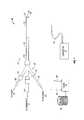
- FIG. 1is a schematic diagram of a microwave ablation system according to an embodiment of the present disclosure
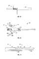
- FIG. 2is a perspective, cross-sectional view of a microwave antenna assembly according to the present disclosure
- FIG. 3is an enlarged, cross-sectional view of a portion of the microwave antenna assembly of FIG. 2 ;
- FIG. 4is an enlarged, cross-sectional view of a portion of the microwave antenna assembly of FIG. 2 ;
- FIG. 5is a side view of a distal portion of a feedline of the microwave antenna assembly of FIG. 2 ;
- FIG. 6is a schematic illustration of a balanced dipole antenna according to an embodiment of the present disclosure.
- FIG. 7is a schematic illustration of an unbalanced dipole antenna according to an embodiment of the present disclosure.
- FIG. 8is a side view of the unbalanced dipole antenna of the microwave antenna assembly of FIG. 2 ;
- FIG. 9is an enlarged, cross-sectional view of a distal end of the microwave antenna assembly of FIG. 2 ;
- FIG. 10is a side view of a radiating section of the microwave antenna assembly of FIG. 2 ;
- FIG. 11is a side view of a tip and a sheath of the microwave antenna assembly of FIG. 2 ;
- FIG. 12is a side view of is proximal end of the feedline of the microwave antenna assembly of FIG. 2 ;
- FIG. 13is a cross-sectional view of the connection hub and a proximal end of the microwave antenna assembly of FIG. 2 ;
- FIG. 14is a schematic view of inflow tubes of the microwave antenna assembly of FIG. 2 ;
- FIG. 15is a side view of a microwave antenna assembly according to one embodiment of the present disclosure.
- FIGS. 16 and 17are perspective cross-sectional views of the microwave antenna of FIG. 15 ;
- FIG. 18is a cross-sectional, enlarged perspective view of the microwave antenna of FIG. 15 ;
- FIG. 19is a schematic diagram of a microwave ablation system according to an embodiment of the present disclosure.
- FIG. 20is a perspective, cross-sectional view of a microwave antenna assembly according to the present disclosure.
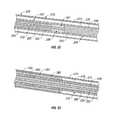
- FIG. 21is an enlarged, cross-sectional view of a portion of the microwave antenna assembly of FIG. 20 ;
- FIG. 22is an enlarged, cross-sectional view of a portion of the microwave antenna assembly of FIG. 20 ;
- FIG. 23is an enlarged, cross-sectional view of a portion of the microwave antenna assembly of FIG. 20 .
- FIG. 1shows a microwave ablation system 10 that includes a microwave antenna assembly 12 coupled to a microwave generator 14 via a flexible coaxial cable 16 .
- the generator 14is configured to provide microwave energy at an operational frequency from about 500 MHz to about 10,000 MHz.
- the antenna assembly 12is generally comprised of radiating section 18 connected by a feedline 20 (or shaft) to the cable 16 . More specifically, the antenna assembly 12 is coupled to the cable 16 through a connection hub 22 .
- the connection hub 22includes an outlet fluid port 30 and an inlet fluid port 32 that are connected in fluid communication with a sheath 38 .
- the sheath 38encloses the radiating section 18 and the feedline 20 allowing for coolant fluid from the ports 30 and 32 to be supplied and circulated around the antenna assembly 12 .
- the ports 30 and 32are also coupled to a supply pump 34 that is, in turn, coupled to a supply tank 36 .
- the supply tank 36stores the coolant fluid and maintains the fluid at a predetermined temperature.
- the supply tank 36may include a coolant unit which cools the returning liquid from the antenna assembly 12 .
- the coolant fluidmay be a gas and/or a mixture of fluid and gas.
- Assembly 12also includes a tip 48 having a tapered end 24 that terminates, in one embodiment, at a pointed end 26 to allow for insertion into tissue with minimal resistance at a distal end of the radiating section 18 .
- tip 48may be rounded or flat.
- FIG. 2illustrates the radiating section 18 of the antenna assembly 12 having an unbalanced dipole antenna 40 .
- the dipole antenna 40is coupled to the feedline 20 that electrically connects antenna assembly 12 to the generator 14 .
- the feedline 20includes an inner conductor 50 (e.g., wire) surrounded by an inner insulator 52 , which is then surrounded by an outer conductor 56 (e.g., cylindrical conducting sheath).
- the inner and outer conductorsmay be constructed of copper, gold, stainless steel or other conductive metals with similar conductivity values.
- the metalsmay be plated with other materials, e.g., other conductive materials, to improve their properties, e.g., to improve conductivity or decrease energy loss, etc.
- the feedline 20may be formed from a coaxial semi-rigid or flexible cable having a wire with a 0.047′′ outer diameter rated for 50 Ohms.
- the dipole antenna 40includes a proximal portion 42 and a distal portion 44 interconnected by a dielectric spacer at a feed point 46 .
- the distal portion 44 and the proximal portion 42are of different, unequal lengths so that the dipole antenna 40 is unbalanced. In one embodiment, as shown in FIG. 7 , the distal portion 44 may be longer than the proximal portion 42 .
- the proximal portion 42is formed from the inner conductor 50 and the inner insulator 52 which are extended outside the outer conductor 56 , as shown best in FIG. 4 .
- the outer conductor 56 and the inner insulator 52may be relieved relative to the inner conductor 50 to reveal the same, as shown in FIG. 5 .
- the distal portion 44includes a conductive member 45 that may be formed from any type of conductive material, such as metals (e.g., copper, stainless steel, tin, and various alloys thereof).
- the distal portion 44may have a solid structure and may be formed from solid wire (e.g., 10 AWG).
- the distal portion 44may be formed from a hollow sleeve of an outer conductor of coaxial cable or another cylindrical conductor.
- the cylindrical conductormay then be filled with solder to convert the cylinder into a solid shaft. More specifically, the solder may be heated to a temperature sufficient to liquefy the solder within the cylindrical conductor (e.g., 500° F.) thereby creating a solid shaft.
- the distal portion 44may also be formed from solid wire or a cylindrical conductor filled with solder.
- the distal portion 44is thereafter coupled to the inner conductor 50 , as shown in FIG. 4 . This may be accomplished by soldering the distal portion 44 to the distal end of the inner conductor 50 , such as by melting the solder of the distal portion 44 and inserting the inner conductor 50 therein.
- the unbalanced dipole antenna 40provides for better impedance matching during ablation. Variation in tissue properties during ablation complicates real part impedance matching of microwave ablation antennas. Over the course of an ablation, a given position on the dipole varies in real impedance due to the resulting dynamic current and voltage relationship.
- FIG. 6shows the difficulty in matching real part impedance using a half-wave dipole antenna which includes two portions of equal lengths, at the center of the dipole the voltage is minimized and the current is maximized. However, the real part impedance is minimized and is maximized at the ends of the proximal and distal portions 42 and 44 .
- the unbalanced dipole antenna 40 of the present disclosureminimizes the integration over ablation time of the difference between the feed point real part impedance and the impedance of the cable 16 .
- the unbalanced half-wave dipoleprovides a better match of initial impedance to real part impedance by placing the gap between the proximal and distal portions 42 and 44 away from the center of the dipole antenna 40 .
- the length of the distal portion 40is about 20 mm to minimize return loss of the assembly 12 .
- FIG. 8illustrates the distal portion 44 attached to the proximal portion 42 .
- the distal portion 44may be soldered to the inner conductor 50 of the proximal portion 42 to establish electromechanical contact therebetween.
- the distal portion 44may be attached to the proximal portion 42 by liquefying the solder of the distal portion 44 and inserting the distal end of the inner conductor 50 therein. A portion of the distal end of the inner conductor 50 is inserted into the distal portion 44 such that a dipole feed gap “G” remains between the proximal and distal portions 42 and 44 at the feed point 46 .
- the gap “G”may be from about 1 mm to about 3 mm.
- the dipole feed gap “G” of the antennais the first structure the coaxial field mode encounters upon transfer to free space. The gap therefore plays an important role in the return loss, or system-to-antenna impedance match.
- the gap “G”is thereafter filled with a dielectric material to form the dielectric spacer at the feed point 46 .
- the inner insulator 52is extended into the feed point 46 .
- the dielectric materialmay be polytetrafluoroethylene (PTFE), such as Teflon® sold by DuPont of Willmington, Del.
- the gap “C”may be coated via a dielectric seal coating as discussed in more detail below.
- the distal portion 44is coupled to the tip 48 , which may be formed from a variety of heat-resistant materials suitable for penetrating tissue, such as metals (e.g., stainless steel) and various thermoplastic materials, such as polyetherimide, polyamide thermoplastic resins, an example of which is Ultem® sold by General Electric Co. of Fairfield, Conn.
- the tip 48may be machined from various stock rods to obtain a desired shape.
- the tip 48may be attached to the distal portion 44 using various adhesives, such as epoxy seal 49 . If the tip 48 is metal, the tip 48 may be soldered to the distal portion 44 .
- FIG. 11illustrates various shapes and forms of the tip 48 , namely a stainless steel tip 48 a and a dielectric tip 48 b .
- Both tips 48 a and 48 bincludes an insertion base 51 having an external diameter that is smaller than diameter of the tips 48 a and 49 allowing for easier insertion into the sheath 38 .
- This configurationalso provides for a better seal between the tip 48 and the sheath 38 as discussed in more detail below.
- the antenna assembly 12also includes a choke 60 .
- the choke 60is disposed around the feedline 20 and includes an inner dielectric layer 62 and an outer conductive layer 64 .
- the choke 60is a proximally positioned quarter-wave length shorted choke.
- the choke 60is implemented as a quarter-wave length shorted by using the outer conductive layer 64 around the outer conductor 56 of the feedline 20 separated by the dielectric layer.
- the choke 60is shorted to the outer conductor 56 of the feedline 20 at the proximal end of the choke 60 by soldering or other means.
- the dielectric layer 32is formed from a fluoropolymer, such as tetrafluorethylene, perfluorpropylene, and the like, and has a thickness of about 0.005 inches.
- the outer conductive layer 34may be formed from a so-called “perfect conductor” material, such as a highly conductive metal (e.g., copper).
- the choke 60may be a quarter-wavelength shorted choke, a half-wavelength open choke, and inverted quarter-wavelength shorted choke or a gap cancellation choke.
- the choke 60confines the microwave energy from the generator 14 to the radiating section 20 of the assembly 12 , thereby limiting the microwave energy deposition zone length along the feedline 20 .
- the choke 28provides high impedance to microwave energy conducted down the outside of the feedline 20 , thereby limiting energy deposition to the end of the antenna.
- a shorted quarter-wave choke placed at the high impedance point of the proximal portion 42 on the antenna assembly 12confines antenna currents to the radiating section 18 of the assembly 12 , reducing the length and maximizing the cross-sectional diameter of ablations due to nearly spherical power dissipation zones.
- the dielectric of dielectric layer 62extends past the choke conductor layer 64 toward the distal end of the assembly 12 , as shown in FIG. 10 .
- the dielectric layer 62may extend past the choke conductor layer 64 by about 6 mm.
- This extended dielectricimproves the performance of the choke 60 by placing a capacitance between the proximal portion 42 of the dipole and the outer surface of the choke conductor layer 64 thereby blocking currents from jumping onto the choke conductor layer 64 .
- the capacitance formed by the dielectricis an impedance barrier to microwave currents which would otherwise jump from the proximal portion 42 to the outer surface of the choke 60 near the entrance thereof avoiding the choke structure completely. Instead, these currents are directed into the quarter-wave choke 60 by the extended dielectric, improving its effectiveness.
- the wavelength increase due to tissue desiccationcauses the high impedance point on the proximal portion 42 to move proximally along the assembly 12 .
- An effective chokemust present high impedance at this variable point.
- the extended dielectriceffectively acts as a variable position choke, covering the range over which this point shifts, maintaining choke effectiveness as long as the high impedance point of the proximal portion 42 stays within the extended dielectric boundaries.
- the dielectric layer 62may be extended to any length between the choke conductive layer 64 and the feed point 46 .
- the dielectric layer 62may be formed by applying a dielectric shrink material, such as 5/64′′ thick PTFE shrink wrap to the outer conductor 56 .
- a dielectric shrink materialsuch as 5/64′′ thick PTFE shrink wrap
- the materialis heated so that the material melts and sets about the outer conductor 56 .
- the heatingmay be accomplished by hot air blowers, which can provide a hot air stream of about 750° F.
- Multiple layers of the PTFE shrink wrapmay be applied and consecutively heated to form the dielectric layer 62 of desired thickness.
- three or more layers of the PTFE shrink wrapare applied.
- the shrink materialmay also be applied over the choke conductive layer 64 to enclose the choke conductive layer 64 .
- the conductor layer 64may be formed by applying one or more layers of a conductive metal foil (e.g., copper) onto the dielectric layer 62 .
- the foilmay extend past the proximal end of the dielectric layer 62 as shown in FIG. 12 .
- the foilmay be attached to the dielectric layer 62 using various types of adhesives (e.g., ultraviolet light activated glue, epoxy, etc.).
- the proximal end of the foil which extends past the dielectric layer 62may be attached to the feedline 20 by means of a so-called “wire-wrap” technique to provide a good electrical connection to the foil and the feedline 20 as shown in FIG. 12 .
- the wireis wrapped around the copper foil at the point where the foil begins to taper down past the dielectric layer 62 .
- the wireis soldered to itself all along the length of the wrap to secure the wire and prevent the wire from unwrapping.
- other methodsmay be used to secure the foil to the feedline 20 , e.g., a hollow cylinder may be placed around the excess foil necking past the dielectric layer 62 .
- the foilmay be substantially the same length as the dielectric layer 62 to obviate the need for securing the proximal end of the foil to the feedline 20 .
- the assembly 12also includes the connection hub 22 , as shown in more detail in FIG. 13 .
- the connection hub 22includes a cable connector 79 and fluid ports 30 and 32 .
- the connection hub 22may include a three-branch luer type connector 72 , with a middle finger 74 being used to house the cable connector 70 and the left and right fingers 76 and 78 to house the outlet and inlet fluid ports 30 and 32 , respectively.
- the connection hub 22also includes a base 81 disposed at a distal end of the middle finger 74 .
- the assembly 12also includes an active coolant system as shown in FIGS. 1 , 13 and 14 . More specifically, the assembly 12 includes sheath 38 that encloses the feedline 20 , the radiating section 18 from the tip 48 to the base 81 .
- the coolantis supplied by the pump 34 and is circulated in the space between the radiating section 18 , the feedline 20 and the sheath 38 . Since the radiating section 18 and the feedline 20 are in direct contact with the coolant fluid these components of the assembly 12 are sealed to prevent the ingress or egress of fluids. This may be accomplished by applying any type of melt-processable polymers using conventional injection molding and screw extrusion techniques.
- a sleeve 63 of fluorinated ethylene propylene (FEP) shrink wrapmay be applied to the entire assembly 12 , namely the feedline 20 and the radiating section 18 , as shown in FIG. 1 .
- the sleeve 63is then heated to seal the choke 60 , the feedline 20 and radiating section 18 .
- the resulting FEP sealprevents coolant fluid from penetrating into the assembly 12 .
- the sleevemay be applied after applying the outer conductive layer 64 .
- FEPmay also be applied at the point where the inner conductor 50 and the inner insulator 52 are extended past the outer conductor 56 , thereby creating an air space 53 as shown in FIG. 4 .
- the sheath 38may be any type of rigid tube, such as a catheter manufactured from polyimide and other types of polymers.
- the sheath 38may be assembled by initially securing the tip 48 to the distal end of the sheath 38 and then inserting the combined sheath and tip assembly onto the assembly 12 .
- the sheath 38is also secured to the base 81 of the connection hub 22 and the tip 48 such that the sheath 38 is in fluid communication with the connection hub 22 and defines a chamber 89 between the base 81 and the tip 48 .
- the inflow tube 86may include one or more inflow tubes 86 a and 86 b .
- the inflow tubes 86 a and 86 bmay be any type of flexible tube having an external diameter sufficient to fit inside the chamber 89 ( FIGS. 4 and 9 ) between the feedline 20 and the sheath 38 .
- the inflow tubes 86 a and 86 bare inserted through the outlet fluid port 30 . More specifically, the inflow tube 86 a is inserted almost to the distal end of the distal portion 44 and the inflow tube 86 b is inserted approximately to the feed point 46 as shown in FIG. 14 .
- the inflow tubes 86 a and 86 bare then secured to the radiating section 18 (e.g., using epoxy, glue, etc.).
- the inflow tubes 86 a and 86 bare positioned in this configuration to provide for optimal coolant flow through the sheath 38 .
- the fluid flow from the inflow tube 86 ais ejected into the tip 48 and is reflected in the proximal direction.
- the fluid flow from the inflow tube 86 bprovides for the coolant along the radiating section 18 .
- the pump 34supplies fluid to the assembly 12 through the inflow tubes 86 a and 86 b , thereby circulating the coolant through the entire length of the assembly 12 including the connection hub 22 .
- the fluidis then withdrawn from the middle finger 74 and the left finger 76 through the outlet fluid port 32 .
- the above-discussed coolant systemprovides for circulation of dielectric coolant fluid (e.g., saline, deionized water, etc.) through the entire length of the antenna assembly 12 .
- the dielectric coolant fluidremoves the heat generated by the assembly 12 .
- the dielectric coolant fluidacts as a buffer for the assembly 12 and prevents near field dielectric properties of the assembly 12 from changing due to varying tissue dielectric properties.
- desiccation of the tissue around the radiating section 18results in a drop in tissue complex permittivity by a considerable factor (e.g., about 10).
- the dielectric constant (er′) dropincreases the wavelength of microwave energy in the tissue, which dramatically affects the impedance of un-buffered microwave antenna assemblies, thereby mismatching the antenna assemblies from the system impedance (e.g., impedance of the cable 16 and the generator 14 ).
- the increase in wavelengthalso results in a power dissipation zone that is much longer in length along the assembly 12 than in cross sectional diameter.
- the decrease in tissue conductivity (er′′)also affects the real part of the impedance of the assembly 12 .
- the fluid dielectric buffering according to the present disclosurealso moderates the increase in wavelength of the delivered energy and drop in conductivity of the near field, thereby reducing the change in impedance of the assembly 12 , allowing for more consistent antenna-to-system impedance match and spherical power dissipation zone despite tissue behavior.
- the buffering of wavelength variationalso allows for a more effective choking network.
- the chokemust be placed at the low current point, or high impedance point, on the end of the proximal portion 42 .
- the half wavelength current pattern on the dipole radiating sectionis maintained, making the position of the high impedance point less variable and therefore allowing for a more effective choke network.
- the cable cooling and the dielectric bufferingallow for targeted and efficient energy delivery to the tissue to enable nearly spherical ablation zones and fast ablation times. Either saline or deionized water can be used with the assembly 12 .
- FIGS. 15-18illustrate another embodiment of a microwave antenna assembly 112 of having a radiating section 118 and a feedline 120 that couples the assembly 112 to the cable 16 . More specifically, the antenna assembly 112 is coupled to the cable 16 though a connection hub 122 that includes an outlet fluid port 130 and an inlet fluid port 132 .
- FIGS. 16 and 17illustrate the radiating section 118 of the antenna assembly 112 having an unbalanced dipole antenna 140 in which the sheath 38 is replaced by a metallic conduit (e.g., coolant jacket 200 ) and a solid dielectric loading 190 .
- the dipole antenna 140is coupled to the feedline 120 , which electrically connects antenna assembly 112 to the generator 14 .
- the feedline 120includes an inner conductor 150 (e.g., wire) surrounded by an inner 152 insulator which is then surrounded by an outer conductor 156 (e.g., cylindrical conducting sheath).
- the dipole antenna 140includes a proximal portion 142 and a distal portion 144 interconnected by a dielectric spacer at a feed point 146 .
- the distal portion 144includes a conductive member 145 .
- the distal portion 144 and the proximal portion 142are of different, unequal lengths so that the dipole antenna 40 is unbalanced.
- the proximal portion 142is formed from the inner conductor 150 and the inner insulator 152 which are extended outside the outer conductor 156 .
- the outer conductor 156 and the inner insulator 152may be sliced off to reveal the inner conductor 150 as shown in FIG. 18 .
- the distal portion 144may be formed from any type of conductive material such as metals (e.g., copper, stainless steel, tin, and various alloys thereof.
- the portion 144may have a solid structure and may be formed from solid wire (e.g., 10 AWG) or a cylindrical conductor filled with solder similar to the portion 44 of the assembly 12 .
- the proximal portion 144is thereafter coupled to the inner conductor 150 .
- the antenna assembly 112also includes a choke 160 .
- the choke 160is disposed around the feedline 120 and includes an inner dielectric layer 162 and an outer conductive layer 164 .
- the choke 160is a proximally positioned quarter-wave shorted choke that is shorted to the outer conductor 156 of the feedline 120 at the proximal end of the choke 160 by soldering or other means.
- the dielectric of dielectric layer 162extends past the choke conductor layer 164 toward the distal end of the assembly 112 .
- the assembly 112also includes the connection hub 122 , as shown in FIG. 15 .
- the connection hub 122includes a cable connector 179 and the fluid ports 130 and 132 .
- the connection hub 122may include a three-branch luer type connector 172 , with a middle finger 174 being used to house the cable connector 179 and the left and right fingers 176 and 178 to house the outlet and inlet fluid ports 130 and 132 , respectively.
- the cable connector 179is coupled to the inner conductor 152 and outer conductor 156 that are extended outside the outer conductor 156 at the proximal end of the feedline 120 .
- the connection hub 122also includes a base 181 disposed at a distal end of the middle finger 174 .
- the assembly 112includes one or more inflow tubes 186 which are fed through the right finger 178 .
- the assembly 112includes a solid dielectric loading 190 disposed over the dipole antenna 140 replacing the liquid dielectric material of assembly 112 .
- the solid dielectric loading 190extend from the point of termination of the choke conductor layer 164 .
- the assembly 112includes a fluid seal 192 over the distal end of the choke conductor layer 164 .
- the loading 190may be attached to the seal 192 via glue and other means.
- the loading 190may be cylinder-shaped having a central cavity 198 defined therein suitable for insertion over the antenna 140 .
- the loading 190may also have a tapered end 194 with a pointed tip 196 , thereby obviating the need for the tip 48 .
- the loading 190may also be attached to the distal end of the antenna 140 (e.g., at the distal portion 144 thereof) within the cavity 198 .
- the cavity 198may have a substantially cylindrical shape suitable to fit over the antenna 140 depending on the cross-sectional shape thereof.
- the cavity 198includes a proximal portion 197 and a distal portion 199 with the proximal portion 197 having a larger inner diameter than the distal portion 199 to accommodate the choke dielectric layer 162 .
- the choke layer 162may be extended to any length between the choke conductive layer 164 and the feed point 146 . To accommodate the extended choke layer 162 the depth of the proximal portion 197 varies accordingly.
- the loading 190has an outer diameter being substantially equal to the thickness of the feedline 120 and the inner diameter being substantially equal to the diameter of the dipole antenna 140 . Since the loading 190 is disposed on the dipole antenna 140 and coolant fluid is not configured to contact the loading in this instance, the antenna 140 is not coated with dielectric shrink wrap to seal the antenna's components.
- the dielectric material of the loading 90may have a dielectric constant of from about 2.5 and 150 and may be made from a ceramic material, such as alumina ceramic or a plastic material, such as a polyamide plastic (e.g., VESPEL® available from DuPont of Wilmington, Del.).
- the loading 190acts as a dielectric buffer between the radiating section 118 and the tissue so that as the electrical properties of the tissue change during ablation the antenna assembly 112 remains halfwave resonant and impedance-matched to the energy delivery system (e.g., the generator 14 , the cable 16 , etc.) throughout the ablation.
- the energy delivery systeme.g., the generator 14 , the cable 16 , etc.
- the antenna assembly 112also includes a coolant jacket 200 disposed between the base 181 and the seal 192 .
- the coolant jacket 200maybe formed from stainless steel or other suitable medical grade metals.
- the coolant jacket 200defines a proximal chamber 201 between the choke conductor layer 164 and the coolant jacket 200 into which a dielectric coolant fluid is supplied through the connection hub 122 .
- one or more inflow tube 186 similar to the tubes 86 a and 86 bmay extend into the chamber 201 to circulate the dielectric coolant fluid through the coolant jacket 200 .
- the seal 192is disposed between the coolant jacket 200 and the choke conductor layer 164 at the distal ends thereof.
- the seal 192may be formed from any type of dielectric (e.g., elastomer) and/or conductive material suitable for sealing the chamber 201 from the loading 190 .
- FIGS. 19-23illustrate another embodiment of a microwave antenna assembly 212 adapted to operate between 500 MHz and 10 GHz.
- the microwave antenna assembly 212includes a hybrid design, which combines a choked liquid cooling system with a solid dielectric loading.
- the microwave antenna assembly 212includes a balanced or unbalanced dipole radiating section 218 having a dielectric-filled feed gap.
- the microwave antenna assembly 212may also include a dielectric loading that encloses the dipole antenna 240 to provide for impedance matching and increased axial strength.
- the entire microwave antenna assembly 212is also enclosed in a hybrid housing 270 including a conductive portion and a non-conductive portion.
- the housingprovides a chamber 275 about the antenna assembly 212 allowing for coolant fluid to flow therethrough.
- the fluidmay also act as a dielectric buffer allowing for better impedance matching.
- the microwave antenna assembly 212includes a radiating section 218 and a feedline 220 which couples the assembly 212 to the cable 16 . More specifically, the antenna assembly 212 is coupled to the cable 16 through a connection hub 222 that includes an outlet fluid port 230 , an inlet fluid port 23 and a cable connector 279 .
- the connection hub 222may include a three-branch luer type connector 272 , with a middle branch 274 being used to house the cable connector 279 and the left and right fingers 276 and 278 to house the outlet and inlet fluid ports 230 and 232 , respectively.
- the cable connector 279is coupled to the feedline 120 .
- the assembly 212includes one or more inflow tubes 286 which are fed through the right finger 278 and an outflow tube 288 fed through the left finger 276 .
- FIGS. 20-23illustrate the radiating section 218 of the antenna assembly 212 having a dipole antenna 240 .
- the dipole antenna 240is coupled to the feedline 220 , which electrically connects antenna assembly 212 to the generator 14 .
- the feedline 220includes an inner conductor 250 (e.g., wire) surrounded by an inner insulator 252 .
- the feedline 220also includes an outer conductor 256 (e.g., cylindrical conducting sheath) disposed around the inner insulator 252 in a coaxial configuration.
- the outer conductor 256is also enclosed within an outer insulator 258 .
- the dipole antenna 240includes a proximal portion 242 and a distal portion 244 . More specifically, the exposed outer conductor 256 acts as the second pole of the proximal portion 242 and the exposed portion of the inner conductor 250 acts as the second pole of the distal portion 244 .
- the distal portion 244also includes a conductive member 245 , which may be a solid conductive shaft attached to the inner conductor 250 . In another embodiment, the conductive member 245 may be a cylindrical conductor, which is filled with solder to convert the cylinder into a solid shaft, thereby attaching the conductive member 245 to the inner conductor 250 .
- the antenna assembly 212includes a tip 248 coupled to the distal end of the conductive member 245 .
- the tip 248includes a tapered end that terminates, in one embodiment, at a pointed end ( FIG. 21 ) to allow for insertion into tissue with minimal resistance at a distal end of the radiating section 218 .
- tip 248may be rounded or flat ( FIG. 20 ).
- the tip 248may be formed from a variety of heat-resistant materials suitable for penetrating tissue, such as metals (e.g., stainless steel) and various thermoplastic materials, such as poletherimide, polyamide thermoplastic resins, an example of which is Ultem® available from General Electric Co.
- the tip 248may be machined from various stock rods to obtain a desired shape.
- the tip 248may be attached to the conductive member 245 using various adhesives, e.g., epoxy. If the tip 248 is metal, the tip 248 may be soldered to the conductive member 245 .
- the dipole antenna 240may either have a balanced or unbalanced configuration.
- the proximal and distal portions 242 and 244e.g., first and second poles
- the proximal and dipole portions 242 and 244are of equal radiating lengths.
- the proximal and dipole portions 242 and 244are of different, unequal lengths.
- the proximal and distal portions 242 and 244are interconnected at a feed point 246 , which may be filled by a dielectric spacer 247 or air (e.g., left unfilled).
- the dielectric space 247may be made of various dielectric materials having a permittivity value from about 1 to about 100 to aid in the impedance matching.
- the dielectric spacer 247may be designed to nest within flanges of the proximal and distal portions 242 and 244 .
- the dielectric spacer 247may be of an over-molded design encapsulating the feed point 246 thereby acting as a coolant barrier and providing additional structural strength to the antenna assembly 212 .
- the antenna assembly 212also includes a choke 260 .
- the choke 260has a tubular structure formed from a conductive material and is disposed around the feedline 220 .
- the choke 260is a proximally positioned quarter-wave choke that is shorted to the outer conductor 256 of the feedline 220 at the proximal end of the choke 260 by solder joint or other methods at connection 265 ( FIG. 20 ).
- the choke 260is disposed over the outer insulator 258 , which extends past the choke 260 toward the distal end of the assembly 212 .
- the outer insulator 258partially covers the distal end of the outer conductor 258 , such that a portion of the outer conductor 258 extending beyond the distal end of the choke 260 is covered by the outer insulator 258 while the remaining portion is exposed.
- the extended outer insulator 258provides for blocking capacitance of the currents passing through the proximal portion 242 , so that the current does not jump over the choke 260 . In effect, the extended outer insulator 258 allows the choke 260 to act as a variable position choke without actually physically changing the position of the choke 260 on the antenna assembly 212 .
- the choke 260also includes an entrance (e.g., open distal end of the choke 260 ) positioned at a high impedance point of the proximal portion 242 of the dipole antenna 240 . This configuration confines the microwave currents to the radiating section 218 allowing for generation of roughly spherical ablation volume.
- the antenna assembly 212also includes a tubular dielectric loading 290 disposed around at least a portion of the dipole antenna 240 , namely, around the exposed portion of the outer conductor 256 and the conductive member 245 .
- the dielectric loading 290covers the feed point 246 and extends to the tip 248 .
- the dielectric loading 290may have a tubular structure and may be formed from a variety of dielectric materials, such as ceramic (e.g., titanium oxide, alumina, etc.) or a plastic material (e.g., a polyamide plastic, VESPEL® available from DuPont of Wilmington, Del.).
- the dialectic loading 290may be machined to form a cylinder suitable to fit around the antenna 240 or may be applied directly to the desirable portion of the antenna 240 to form a tubular coating via a variety of methods, such as spray coating, atomic layer deposition, vapor layer deposition and the like.
- the antenna assembly 212includes a tubular housing 270 that encloses the dipole antenna 240 and the feedline 220 .
- the tubular housing 270may have a nonconductive-conductive hybrid design and may include a distal housing portion 272 and a proximal housing portion 274 ,
- the proximal housing portion 272may be formed from either a conductive or nonconductive material to provide structural support to the antenna assembly 212 .
- the nonconductive-conductive hybrid designincludes the proximal housing portion 272 formed from a conductive material and the distal housing portion 274 formed from a non-conductive material.
- the conductive material of the proximal housing portion 272may be stainless steel or other suitable medical grade metal.
- the proximal housing portion 272may be made from a stainless steel hypo-tube to provide for structural support for the proximal portion of the antenna assembly 212 .
- the proximal housing portion 272also impedes any microwave energy (e.g., radiated by the dipole antenna 240 ) from migrating up the antenna assembly 212 .
- the distal housing portion 274may be formed from a dielectric material, such as polyimide, to facilitate the transmission of microwave energy therethrough to irradiate the tissue.
- the distal housing portion 274may be a rigid non-conductive cylinder, such as a hardened plastic tube, of similar diameter as the proximal housing portion 272 .
- the distal housing portion 274may have a larger diameter, such that the proximal housing portion 272 fits within the distal housing portion 274 .
- proximal and distal housing portions 272 and 274may be nested radially, or concentrically, such that the distal housing portion 274 runs the entire length of the antenna assembly 212 , enclosing the proximal housing portion 272 .
- proximal and distal housing portions 272 and 274may be coupled at the truncation of the proximal housing portion 272 as shown in FIG. 20 . This may be accomplished by compression fitting, thread mating, epoxying, welding, and other suitable methods.
- the tip 248may also be coupled to the distal housing portion 274 by compression fitting, thread mating, epoxying, welding, and other methods. Compression fitting and/or welding various metallic components of the antenna assembly 212 allows for increased temperature handling capability and facilitates manufacturability of the antenna assembly 212 .
- the housing 270defines a chamber 275 around the feedline 220 and the radiating section 218 .
- the chamber 275is adapted for circuiting a coolant fluid therethrough along the entire length of the antenna assembly 212 .
- the coolant fluidmay be a dielectric such as water or saline that is supplied though the hub 222 .
- the coolant fluidhas a relatively high dielectric constant similar to tissue in which the antenna assembly 212 is being used, such that the low conductivity of the fluid allows it to act as a dielectric buffer around the radiating section 220 .
- the bufferingallows for impedance matching between the antenna assembly 212 and the tissue, even as the electrical properties of the tissue change as the tissue is being ablated.
- the coolant fluidcools the antenna assembly 212 , including the feedline 220 , enabling greater energy delivery.
- one or more inflow tubes 286may extend into the chamber 275 to circulate the coolant fluid along the feedline 220 , the radiating section 218 and the choke 260 .
- the remaining space within the chamber 275may act as the return path for the fluid, which is then withdrawn through the outflow tube 288 .
- the fluidmay be passed through the choke 260 .
- the choke 260includes a tubular structure having an inner cylindrical casing 261 and an outer cylindrical casing 263 defining a cavity 265 therebetween. The fluid is supplied through the cavity 265 into the chamber 275 .
- the antenna assembly 212includes a dielectric buffering medium 300 which is provided by the outer insulator 258 , the dielectric spacer 247 , dielectric loading 290 and the coolant fluid supplied through the chamber 275 .
- the medium 300acts as a dielectric buffer between the radiating section 218 and the tissue such that as the electrical properties of the tissue change during ablation the antenna assembly 212 remains resonant and impedance-matched to the energy delivery system (e.g., the generator 14 , the cable 16 , etc.) throughout the ablation.
- the energy delivery systeme.g., the generator 14 , the cable 16 , etc.
- the dielectric permittivity values of the components of the medium 300are as follows: outer insulator 258 may range from about 1 to about 30, the dielectric spacer 247 may range from about 2 to about 100, the dielectric loading 290 may range from about 2 to about 150, and the coolant fluid may range from about 30 to about 100.
- the dielectric permittivity values of the constituent materials of the medium 300are selected to provide for a gradual increase in the dielectric permittivity as the radial distance from the feed point 246 increases.
- the outer insulator 258has a lower dielectric permittivity than the dielectric spacer 247 , which, in turn, has a lower dielectric permittivity than the dielectric loading 290 .
- the coolant fluidhas the highest dielectric permittivity. More specifically, the dielectric material loaded in the feed point 246 , which may be filled by a dielectric spacer 247 or air, has a dielectric permittivity value higher than that of the outer insulator 258 but lower than that of the dielectric loading 290 .
- the gradual increase in the dielectric constant of the medium 300is accomplished by providing material of varying dielectric properties. This arrangement allows for better impedance matching of the antenna assembly 212 to the tissue during ablation.
Landscapes
- Health & Medical Sciences (AREA)
- Surgery (AREA)
- Life Sciences & Earth Sciences (AREA)
- Biomedical Technology (AREA)
- Medical Informatics (AREA)
- Nuclear Medicine, Radiotherapy & Molecular Imaging (AREA)
- Electromagnetism (AREA)
- Engineering & Computer Science (AREA)
- Physics & Mathematics (AREA)
- Heart & Thoracic Surgery (AREA)
- Otolaryngology (AREA)
- Molecular Biology (AREA)
- Animal Behavior & Ethology (AREA)
- General Health & Medical Sciences (AREA)
- Public Health (AREA)
- Veterinary Medicine (AREA)
- Surgical Instruments (AREA)
- Radiation-Therapy Devices (AREA)
Abstract
Description
Claims (18)
Priority Applications (6)
| Application Number | Priority Date | Filing Date | Title |
|---|---|---|---|
| US12/253,457US9113924B2 (en) | 2008-10-17 | 2008-10-17 | Choked dielectric loaded tip dipole microwave antenna |
| EP09173268.5AEP2177173B1 (en) | 2008-10-17 | 2009-10-16 | Choked dielectric loaded tip dipole microwave antenna |
| JP2009239894AJP5513837B2 (en) | 2008-10-17 | 2009-10-16 | Choke dielectric-loaded tip dipole microwave antenna |
| EP16197558.6AEP3150160B1 (en) | 2008-10-17 | 2009-10-16 | Choked dielectric loaded tip dipole microwave antenna |
| JP2014068349AJP5808835B2 (en) | 2008-10-17 | 2014-03-28 | Choke dielectric-loaded tip dipole microwave antenna |
| US14/804,504US10188460B2 (en) | 2008-10-17 | 2015-07-21 | Choked dielectric loaded tip dipole microwave antenna |
Applications Claiming Priority (1)
| Application Number | Priority Date | Filing Date | Title |
|---|---|---|---|
| US12/253,457US9113924B2 (en) | 2008-10-17 | 2008-10-17 | Choked dielectric loaded tip dipole microwave antenna |
Related Child Applications (1)
| Application Number | Title | Priority Date | Filing Date |
|---|---|---|---|
| US14/804,504ContinuationUS10188460B2 (en) | 2008-10-17 | 2015-07-21 | Choked dielectric loaded tip dipole microwave antenna |
Publications (2)
| Publication Number | Publication Date |
|---|---|
| US20100097284A1 US20100097284A1 (en) | 2010-04-22 |
| US9113924B2true US9113924B2 (en) | 2015-08-25 |
Family
ID=41259529
Family Applications (2)
| Application Number | Title | Priority Date | Filing Date |
|---|---|---|---|
| US12/253,457Active2033-05-21US9113924B2 (en) | 2008-10-17 | 2008-10-17 | Choked dielectric loaded tip dipole microwave antenna |
| US14/804,504Active2030-06-21US10188460B2 (en) | 2008-10-17 | 2015-07-21 | Choked dielectric loaded tip dipole microwave antenna |
Family Applications After (1)
| Application Number | Title | Priority Date | Filing Date |
|---|---|---|---|
| US14/804,504Active2030-06-21US10188460B2 (en) | 2008-10-17 | 2015-07-21 | Choked dielectric loaded tip dipole microwave antenna |
Country Status (3)
| Country | Link |
|---|---|
| US (2) | US9113924B2 (en) |
| EP (2) | EP2177173B1 (en) |
| JP (2) | JP5513837B2 (en) |
Cited By (19)
| Publication number | Priority date | Publication date | Assignee | Title |
|---|---|---|---|---|
| US20150361787A1 (en)* | 2013-01-29 | 2015-12-17 | Schlumberger Technology Corporation | Wireless communication and telemetry for completions |
| US20160030112A1 (en)* | 2008-10-17 | 2016-02-04 | Joseph D. Brannan | Choked dielectric loaded tip dipole microwave antenna |
| US20170014638A1 (en)* | 2015-07-13 | 2017-01-19 | Symple Surgical, Inc. | Cable with microwave emitter |
| US9681916B2 (en) | 2012-01-06 | 2017-06-20 | Covidien Lp | System and method for treating tissue using an expandable antenna |
| US9693823B2 (en) | 2012-01-06 | 2017-07-04 | Covidien Lp | System and method for treating tissue using an expandable antenna |
| US9949794B2 (en) | 2008-03-27 | 2018-04-24 | Covidien Lp | Microwave ablation devices including expandable antennas and methods of use |
| US10022186B2 (en) | 2008-08-28 | 2018-07-17 | Covidien Lp | Microwave antenna with cooled handle |
| US10028787B2 (en) | 2010-02-26 | 2018-07-24 | Covidien Lp | Tunable microwave ablation probe |
| US10321962B2 (en) | 2007-11-01 | 2019-06-18 | Covidien Lp | Method for volume determination and geometric reconstruction |
| US10327845B2 (en) | 2010-01-25 | 2019-06-25 | Covidien Lp | System and method for monitoring ablation size |
| US10390882B2 (en) | 2009-09-29 | 2019-08-27 | Covidien Lp | Flow rate monitor for fluid cooled microwave ablation probe |
| US20200000512A1 (en)* | 2018-07-02 | 2020-01-02 | Covidien Lp | Electrically-insulative shafts, methods of manufacturing electrically-insulative shafts, and energy-based surgical instruments incorporating electrically-insulative shafts |
| US10660691B2 (en) | 2015-10-07 | 2020-05-26 | Angiodynamics, Inc. | Multiple use subassembly with integrated fluid delivery system for use with single or dual-lumen peristaltic tubing |
| US10675089B2 (en) | 2009-09-29 | 2020-06-09 | Covidien Lp | Management of voltage standing wave ratio at skin surface during microwave ablation |
| US10987152B2 (en) | 2010-02-19 | 2021-04-27 | Covidien Lp | Ablation devices with dual operating frequencies, systems including same, and methods of adjusting ablation volume using same |
| IL265384B (en)* | 2017-03-30 | 2022-08-01 | Creo Medical Ltd | Electrosurgical device |
| US11432870B2 (en) | 2016-10-04 | 2022-09-06 | Avent, Inc. | Cooled RF probes |
| US12318133B2 (en) | 2008-01-23 | 2025-06-03 | Covidien Lp | Choked microwave antenna |
| USD1084316S1 (en) | 2023-11-20 | 2025-07-15 | Angiodynamics, Inc. | Ferrule |
Families Citing this family (57)
| Publication number | Priority date | Publication date | Assignee | Title |
|---|---|---|---|---|
| US7553309B2 (en) | 2004-10-08 | 2009-06-30 | Covidien Ag | Electrosurgical system employing multiple electrodes and method thereof |
| US8280525B2 (en) | 2007-11-16 | 2012-10-02 | Vivant Medical, Inc. | Dynamically matched microwave antenna for tissue ablation |
| US8435237B2 (en) | 2008-01-29 | 2013-05-07 | Covidien Lp | Polyp encapsulation system and method |
| US8192427B2 (en) | 2008-06-09 | 2012-06-05 | Tyco Healthcare Group Lp | Surface ablation process with electrode cooling methods |
| US8403924B2 (en) | 2008-09-03 | 2013-03-26 | Vivant Medical, Inc. | Shielding for an isolation apparatus used in a microwave generator |
| US8197473B2 (en) | 2009-02-20 | 2012-06-12 | Vivant Medical, Inc. | Leaky-wave antennas for medical applications |
| US8202270B2 (en) | 2009-02-20 | 2012-06-19 | Vivant Medical, Inc. | Leaky-wave antennas for medical applications |
| US9277969B2 (en) | 2009-04-01 | 2016-03-08 | Covidien Lp | Microwave ablation system with user-controlled ablation size and method of use |
| US8463396B2 (en) | 2009-05-06 | 2013-06-11 | Covidien LLP | Power-stage antenna integrated system with high-strength shaft |
| US8292881B2 (en) | 2009-05-27 | 2012-10-23 | Vivant Medical, Inc. | Narrow gauge high strength choked wet tip microwave ablation antenna |
| US8235981B2 (en) | 2009-06-02 | 2012-08-07 | Vivant Medical, Inc. | Electrosurgical devices with directional radiation pattern |
| US8328800B2 (en) | 2009-08-05 | 2012-12-11 | Vivant Medical, Inc. | Directive window ablation antenna with dielectric loading |
| USD634010S1 (en) | 2009-08-05 | 2011-03-08 | Vivant Medical, Inc. | Medical device indicator guide |
| US9031668B2 (en)* | 2009-08-06 | 2015-05-12 | Covidien Lp | Vented positioner and spacer and method of use |
| US8328801B2 (en) | 2009-08-17 | 2012-12-11 | Vivant Medical, Inc. | Surface ablation antenna with dielectric loading |
| US8069553B2 (en) | 2009-09-09 | 2011-12-06 | Vivant Medical, Inc. | Method for constructing a dipole antenna |
| US9113925B2 (en)* | 2009-09-09 | 2015-08-25 | Covidien Lp | System and method for performing an ablation procedure |
| US8355803B2 (en) | 2009-09-16 | 2013-01-15 | Vivant Medical, Inc. | Perfused core dielectrically loaded dipole microwave antenna probe |
| US9095359B2 (en) | 2009-09-18 | 2015-08-04 | Covidien Lp | Tissue ablation system with energy distribution |
| US8394087B2 (en)* | 2009-09-24 | 2013-03-12 | Vivant Medical, Inc. | Optical detection of interrupted fluid flow to ablation probe |
| US8568401B2 (en) | 2009-10-27 | 2013-10-29 | Covidien Lp | System for monitoring ablation size |
| US8430871B2 (en) | 2009-10-28 | 2013-04-30 | Covidien Lp | System and method for monitoring ablation size |
| US8382750B2 (en)* | 2009-10-28 | 2013-02-26 | Vivant Medical, Inc. | System and method for monitoring ablation size |
| US8394092B2 (en)* | 2009-11-17 | 2013-03-12 | Vivant Medical, Inc. | Electromagnetic energy delivery devices including an energy applicator array and electrosurgical systems including same |
| US8491579B2 (en) | 2010-02-05 | 2013-07-23 | Covidien Lp | Electrosurgical devices with choke shorted to biological tissue |
| US8409188B2 (en) | 2010-03-26 | 2013-04-02 | Covidien Lp | Ablation devices with adjustable radiating section lengths, electrosurgical systems including same, and methods of adjusting ablation fields using same |
| US10039601B2 (en) | 2010-03-26 | 2018-08-07 | Covidien Lp | Ablation devices with adjustable radiating section lengths, electrosurgical systems including same, and methods of adjusting ablation fields using same |
| US9561076B2 (en) | 2010-05-11 | 2017-02-07 | Covidien Lp | Electrosurgical devices with balun structure for air exposure of antenna radiating section and method of directing energy to tissue using same |
| USD673685S1 (en) | 2010-09-08 | 2013-01-01 | Vivant Medical, Inc. | Microwave device spacer and positioner with arcuate slot |
| US8945144B2 (en) | 2010-09-08 | 2015-02-03 | Covidien Lp | Microwave spacers and method of use |
| US8968289B2 (en) | 2010-10-22 | 2015-03-03 | Covidien Lp | Microwave spacers and methods of use |
| US9055957B2 (en)* | 2010-12-23 | 2015-06-16 | Covidien Lp | Microwave field-detecting needle assemblies, methods of manufacturing same, methods of adjusting an ablation field radiating into tissue using same, and systems including same |
| US8932281B2 (en) | 2011-01-05 | 2015-01-13 | Covidien Lp | Energy-delivery devices with flexible fluid-cooled shaft, inflow/outflow junctions suitable for use with same, and systems including same |
| US9011421B2 (en) | 2011-01-05 | 2015-04-21 | Covidien Lp | Energy-delivery devices with flexible fluid-cooled shaft, inflow/outflow junctions suitable for use with same, and systems including same |
| US9017319B2 (en) | 2011-01-05 | 2015-04-28 | Covidien Lp | Energy-delivery devices with flexible fluid-cooled shaft, inflow/outflow junctions suitable for use with same, and systems including same |
| US9770294B2 (en) | 2011-01-05 | 2017-09-26 | Covidien Lp | Energy-delivery devices with flexible fluid-cooled shaft, inflow/outflow junctions suitable for use with same, and systems including same |
| US9579150B2 (en) | 2011-04-08 | 2017-02-28 | Covidien Lp | Microwave ablation instrument with interchangeable antenna probe |
| AU2014253563B2 (en)* | 2011-05-31 | 2015-12-24 | Covidien Lp | Modified wet tip antenna design |
| US9407004B2 (en) | 2012-07-25 | 2016-08-02 | Tyco Electronics Corporation | Multi-element omni-directional antenna |
| WO2014121229A1 (en)* | 2013-02-01 | 2014-08-07 | Biomat Sciences | Method and device for treating caries using locally delivered microwave energy |
| US9987087B2 (en)* | 2013-03-29 | 2018-06-05 | Covidien Lp | Step-down coaxial microwave ablation applicators and methods for manufacturing same |
| US10765477B2 (en)* | 2014-03-10 | 2020-09-08 | Wisconsin Alumni Research Foundation | Microwave ablation antenna system |
| US10090606B2 (en)* | 2015-07-15 | 2018-10-02 | At&T Intellectual Property I, L.P. | Antenna system with dielectric array and methods for use therewith |
| CN105816240B (en)* | 2016-05-24 | 2018-09-28 | 赛诺微医疗科技(浙江)有限公司 | For the antenna module of microwave ablation and using its microwave melt needle |
| US11197715B2 (en)* | 2016-08-02 | 2021-12-14 | Covidien Lp | Ablation cable assemblies and a method of manufacturing the same |
| WO2018140816A1 (en) | 2017-01-26 | 2018-08-02 | Broncus Medical Inc. | Bronchoscopic-based microwave ablation system and method |
| WO2018147835A1 (en)* | 2017-02-07 | 2018-08-16 | Hewlett-Packard Development Company, L.P. | Fluidic conductive trace based radio-frequency identification |
| CN107260301B (en)* | 2017-04-20 | 2021-04-02 | 南通融锋医疗科技有限公司 | True circle microwave ablation antenna and system |
| GB2562290B (en)* | 2017-05-11 | 2023-04-05 | Gyrus Medical Ltd | Microwave ablation antenna assemblies |
| US10707581B2 (en) | 2018-01-03 | 2020-07-07 | Wisconsin Alumni Research Foundation | Dipole antenna for microwave ablation |
| GB2573823A (en)* | 2018-05-19 | 2019-11-20 | Creo Medical Ltd | Electrosurgical ablation instrument |
| CN108670405A (en)* | 2018-05-25 | 2018-10-19 | 南通融锋医疗科技有限公司 | A non-puncturing microwave ablation antenna and its application |
| GB2580424B (en)* | 2019-01-11 | 2023-02-01 | Gyrus Medical Ltd | Microwave ablation antenna assemblies |
| WO2021207264A2 (en)* | 2020-04-10 | 2021-10-14 | Intuitive Surgical Operations, Inc. | Flexible instruments with patterned antenna assemblies having variable recoverable flexibility |
| CN113116513B (en)* | 2021-02-24 | 2022-12-13 | 电子科技大学 | A Microwave Ablation Antenna Based on Substrate Integrated Coaxial Cable |
| CN113576657B (en)* | 2021-05-08 | 2024-05-24 | 南京瑞波医学科技有限公司 | Medical ablation antenna |
| US12070266B2 (en) | 2021-06-29 | 2024-08-27 | Varian Medical Systems, Inc. | Microwave ablation probe with choke |
Citations (157)
| Publication number | Priority date | Publication date | Assignee | Title |
|---|---|---|---|---|
| DE390937C (en) | 1922-10-13 | 1924-03-03 | Adolf Erb | Device for internal heating of furnace furnaces for hardening, tempering, annealing, quenching and melting |
| DE1099658B (en) | 1959-04-29 | 1961-02-16 | Siemens Reiniger Werke Ag | Automatic switch-on device for high-frequency surgical devices |
| FR1275415A (en) | 1960-09-26 | 1961-11-10 | Device for detecting disturbances for electrical installations, in particular electrosurgery | |
| DE1139927B (en) | 1961-01-03 | 1962-11-22 | Friedrich Laber | High-frequency surgical device |
| DE1149832B (en) | 1961-02-25 | 1963-06-06 | Siemens Reiniger Werke Ag | High frequency surgical apparatus |
| FR1347865A (en) | 1962-11-22 | 1964-01-04 | Improvements to diathermo-coagulation devices | |
| DE1439302A1 (en) | 1963-10-26 | 1969-01-23 | Siemens Ag | High-frequency surgical device |
| US3631363A (en) | 1969-11-14 | 1971-12-28 | Gen Electric | High-frequency cavity oscillator having improved tuning means |
| SU401367A1 (en) | 1971-10-05 | 1973-10-12 | Тернопольский государственный медицинский институт | BIAKTIVNYE ELECTRO SURGICAL INSTRUMENT |
| DE2439587A1 (en) | 1973-08-23 | 1975-02-27 | Matburn Holdings Ltd | ELECTROSURGICAL DEVICE |
| DE2455174A1 (en) | 1973-11-21 | 1975-05-22 | Termiflex Corp | INPUT / OUTPUT DEVICE FOR DATA EXCHANGE WITH DATA PROCESSING DEVICES |
| DE2407559A1 (en) | 1974-02-16 | 1975-08-28 | Dornier System Gmbh | Tissue heat treatment probe - has water cooling system which ensures heat development only in treated tissues |
| DE2415263A1 (en) | 1974-03-29 | 1975-10-02 | Aesculap Werke Ag | Surgical H.F. coagulation probe has electrode tongs - with exposed ends of insulated conductors forming tong-jaws |
| DE2429021A1 (en) | 1974-06-18 | 1976-01-08 | Erbe Elektromedizin | Remote control for HF surgical instruments - uses cable with two conductors at most |
| FR2235669B1 (en) | 1973-07-07 | 1976-05-07 | Lunacek Boris | |
| DE2460481A1 (en) | 1974-12-20 | 1976-06-24 | Delma Elektro Med App | Electrode grip for remote HF surgical instrument switching - has shaped insulated piece with contact ring of sterilizable (silicon) rubber |
| DE2602517A1 (en) | 1975-01-23 | 1976-07-29 | Dentsply Int Inc | ELECTROSURGICAL DEVICE |
| DE2504280A1 (en) | 1975-02-01 | 1976-08-05 | Hans Heinrich Prof Dr Meinke | DEVICE FOR ELECTRIC TISSUE CUTTING IN SURGERY |
| DE2627679A1 (en) | 1975-06-26 | 1977-01-13 | Marcel Lamidey | HEMATISTIC HIGH FREQUENCY EXTRACTOR FORCEPS |
| DE2540968A1 (en) | 1975-09-13 | 1977-03-17 | Erbe Elektromedizin | Circuit for bipolar coagulation tweezers - permits preparation of tissues prior to coagulation |
| FR2276027B3 (en) | 1974-06-25 | 1977-05-06 | Medical Plastics Inc | |
| DE2820908A1 (en) | 1977-05-16 | 1978-11-23 | Joseph Skovajsa | DEVICE FOR THE LOCAL TREATMENT OF A PATIENT IN PARTICULAR FOR ACUPUNCTURE OR AURICULAR THERAPY |
| DE2803275A1 (en) | 1978-01-26 | 1979-08-02 | Aesculap Werke Ag | HF surgical appts. with active treatment and patient electrodes - has sensor switching generator to small voltage when hand-operated switch is closed |
| DE2823291A1 (en) | 1978-05-27 | 1979-11-29 | Rainer Ing Grad Koch | Coagulation instrument automatic HF switching circuit - has first lead to potentiometer and second to transistor base |
| SU727201A2 (en) | 1977-11-02 | 1980-04-15 | Киевский Научно-Исследовательский Институт Нейрохирургии | Electric surgical apparatus |
| FR2313708B1 (en) | 1975-06-02 | 1980-07-04 | Sybron Corp | |
| US4292960A (en) | 1979-04-30 | 1981-10-06 | Rca Corporation | Apparatus and method for application of radioactive and microwave energy to the body |
| US4311154A (en) | 1979-03-23 | 1982-01-19 | Rca Corporation | Nonsymmetrical bulb applicator for hyperthermic treatment of the body |
| DE3045996A1 (en) | 1980-12-05 | 1982-07-08 | Medic Eschmann Handelsgesellschaft für medizinische Instrumente mbH, 2000 Hamburg | Electro-surgical scalpel instrument - has power supply remotely controlled by surgeon |
| FR2517953A1 (en) | 1981-12-10 | 1983-06-17 | Alvar Electronic | Diaphanometer for optical examination of breast tissue structure - measures tissue transparency using two plates and optical fibre bundle cooperating with photoelectric cells |
| US4397313A (en) | 1981-08-03 | 1983-08-09 | Clini-Therm Corporation | Multiple microwave applicator system and method for microwave hyperthermia treatment |
| US4462412A (en) | 1980-04-02 | 1984-07-31 | Bsd Medical Corporation | Annular electromagnetic radiation applicator for biological tissue, and method |
| DE3143421C2 (en) | 1980-11-04 | 1985-05-02 | The Agency Of Industrial Science And Technology, Tokio/Tokyo | Laser scalpel |
| FR2502935B1 (en) | 1981-03-31 | 1985-10-04 | Dolley Roger | METHOD AND DEVICE FOR CONTROLLING THE COAGULATION OF TISSUES USING A HIGH FREQUENCY CURRENT |
| US4572190A (en) | 1983-05-26 | 1986-02-25 | Cgr/Mev | Hyperthermia apparatus |
| US4612940A (en) | 1984-05-09 | 1986-09-23 | Scd Incorporated | Microwave dipole probe for in vivo localized hyperthermia |
| FR2573301B3 (en) | 1984-11-16 | 1987-04-30 | Lamidey Gilles | SURGICAL PLIERS AND ITS CONTROL AND CONTROL APPARATUS |
| DE2946728C2 (en) | 1979-11-20 | 1987-07-30 | Erbe Elektromedizin Gmbh, 7400 Tuebingen, De | |
| DE3120102C2 (en) | 1981-05-20 | 1987-08-20 | Fischer Met Gmbh, 7800 Freiburg, De | |
| US4700716A (en) | 1986-02-27 | 1987-10-20 | Kasevich Associates, Inc. | Collinear antenna array applicator |
| EP0246350A1 (en) | 1986-05-23 | 1987-11-25 | Erbe Elektromedizin GmbH. | Coagulation electrode |
| DE8712328U1 (en) | 1987-09-11 | 1988-02-18 | Jakoubek, Franz, 7201 Emmingen-Liptingen | Endoscopy forceps |
| DE3711511C1 (en) | 1987-04-04 | 1988-06-30 | Hartmann & Braun Ag | Method for determining gas concentrations in a gas mixture and sensor for measuring thermal conductivity |
| DE3510586C2 (en) | 1985-03-23 | 1988-07-28 | Erbe Elektromedizin Gmbh, 7400 Tuebingen, De | |
| US4798215A (en) | 1984-03-15 | 1989-01-17 | Bsd Medical Corporation | Hyperthermia apparatus |
| US4825880A (en) | 1987-06-19 | 1989-05-02 | The Regents Of The University Of California | Implantable helical coil microwave antenna |
| US4841988A (en) | 1987-10-15 | 1989-06-27 | Marquette Electronics, Inc. | Microwave hyperthermia probe |
| US4934365A (en) | 1988-06-30 | 1990-06-19 | Massachusetts Institute Of Technology | Non-invasive hyperthermia method and apparatus |
| US4945912A (en) | 1988-11-25 | 1990-08-07 | Sensor Electronics, Inc. | Catheter with radiofrequency heating applicator |
| US4974587A (en) | 1988-12-22 | 1990-12-04 | Bsd Medical Corporation | Applicator array and positioning system for hyperthermia |
| US5057106A (en) | 1986-02-27 | 1991-10-15 | Kasevich Associates, Inc. | Microwave balloon angioplasty |
| US5097844A (en) | 1980-04-02 | 1992-03-24 | Bsd Medical Corporation | Hyperthermia apparatus having three-dimensional focusing |
| US5097845A (en) | 1987-10-15 | 1992-03-24 | Labthermics Technologies | Microwave hyperthermia probe |
| EP0481685A1 (en) | 1990-10-15 | 1992-04-22 | Cook Incorporated | Medical device for localizing a lesion |
| US5129396A (en) | 1988-11-10 | 1992-07-14 | Arye Rosen | Microwave aided balloon angioplasty with lumen measurement |
| JPH055106B2 (en) | 1984-04-05 | 1993-01-21 | Asahi Chemical Ind | |
| DE4238263A1 (en) | 1991-11-15 | 1993-05-19 | Minnesota Mining & Mfg | Adhesive comprising hydrogel and crosslinked polyvinyl:lactam - is used in electrodes for biomedical application providing low impedance and good mechanical properties when water and/or moisture is absorbed from skin |
| EP0521264A3 (en) | 1991-07-03 | 1993-06-16 | W.L. Gore & Associates Gmbh | Antenna device with feed |
| EP0556705A1 (en) | 1992-02-20 | 1993-08-25 | DELMA ELEKTRO-UND MEDIZINISCHE APPARATEBAU GESELLSCHAFT mbH | High frequency surgery device |
| EP0558429A1 (en) | 1992-02-26 | 1993-09-01 | PECHINEY RECHERCHE (Groupement d'Intérêt Economique géré par l'ordonnance no. 67-821 du 23 Septembre 1967) | Method of simultaneous measuring of electrical resistivety and thermal conductivity |
| JPH0540112Y2 (en) | 1987-03-03 | 1993-10-12 | ||
| US5257635A (en) | 1988-11-25 | 1993-11-02 | Sensor Electronics, Inc. | Electrical heating catheter |
| EP0572131A1 (en) | 1992-05-21 | 1993-12-01 | Everest Medical Corporation | Surgical scissors with bipolar coagulation feature |
| US5275597A (en) | 1992-05-18 | 1994-01-04 | Baxter International Inc. | Percutaneous transluminal catheter and transmitter therefor |
| US5295955A (en) | 1992-02-14 | 1994-03-22 | Amt, Inc. | Method and apparatus for microwave aided liposuction |
| US5301687A (en) | 1991-06-06 | 1994-04-12 | Trustees Of Dartmouth College | Microwave applicator for transurethral hyperthermia |
| US5344435A (en) | 1988-07-28 | 1994-09-06 | Bsd Medical Corporation | Urethral inserted applicator prostate hyperthermia |
| US5358515A (en) | 1989-08-16 | 1994-10-25 | Deutsches Krebsforschungzentrum Stiftung Des Offentlichen Rechts | Microwave hyperthermia applicator |
| US5369251A (en) | 1992-09-14 | 1994-11-29 | Kdc Technology Corp. | Microwave interstitial hyperthermia probe |
| JPH06343644A (en) | 1993-05-04 | 1994-12-20 | Gyrus Medical Ltd | Surgical peritoneoscope equipment |
| DE4303882C2 (en) | 1993-02-10 | 1995-02-09 | Kernforschungsz Karlsruhe | Combination instrument for separation and coagulation for minimally invasive surgery |
| US5417210A (en) | 1992-05-27 | 1995-05-23 | International Business Machines Corporation | System and method for augmentation of endoscopic surgery |
| DE3604823C2 (en) | 1986-02-15 | 1995-06-01 | Lindenmeier Heinz | High frequency generator with automatic power control for high frequency surgery |
| JPH07265328A (en) | 1993-11-01 | 1995-10-17 | Gyrus Medical Ltd | Electrode assembly for electric surgery device and electric surgery device using it |
| JPH0856955A (en) | 1994-06-29 | 1996-03-05 | Gyrus Medical Ltd | Electric surgical apparatus |
| US5549639A (en) | 1994-09-16 | 1996-08-27 | Sandia Corporation | Non-invasive hyperthermia apparatus including coaxial applicator having a non-invasive radiometric receiving antenna incorporated therein and method of use thereof |
| JPH08252263A (en) | 1994-12-21 | 1996-10-01 | Gyrus Medical Ltd | Electronic surgical incision instrument and electronic surgical incision device using the same |
| DE29616210U1 (en) | 1996-09-18 | 1996-11-14 | Olympus Winter & Ibe Gmbh, 22045 Hamburg | Handle for surgical instruments |
| JPH0910223A (en) | 1995-06-23 | 1997-01-14 | Gyrus Medical Ltd | Generator and system for electric operation |
| DE19608716C1 (en) | 1996-03-06 | 1997-04-17 | Aesculap Ag | Bipolar surgical holding instrument |
| DE3904558C2 (en) | 1989-02-15 | 1997-09-18 | Lindenmeier Heinz | Automatically power-controlled high-frequency generator for high-frequency surgery |
| US5683382A (en) | 1995-05-15 | 1997-11-04 | Arrow International Investment Corp. | Microwave antenna catheter |
| WO1997041924A1 (en) | 1996-05-06 | 1997-11-13 | Thermal Therapeutics, Inc. | Transcervical intrauterine applicator for intrauterine hyperthermia |
| EP0541930B1 (en) | 1991-10-17 | 1998-03-25 | Smith & Nephew, Inc. | Transmission link for use in surgical instruments |
| WO1997043971A3 (en) | 1996-05-22 | 1998-04-02 | Somnus Medical Tech Inc | Method and apparatus for ablating turbinates |
| DE19751106A1 (en) | 1996-11-27 | 1998-05-28 | Eastman Kodak Co | Laser printer with array of laser diodes |
| US5776176A (en) | 1996-06-17 | 1998-07-07 | Urologix Inc. | Microwave antenna for arterial for arterial microwave applicator |
| DE19717411A1 (en) | 1997-04-25 | 1998-11-05 | Aesculap Ag & Co Kg | Monitoring of thermal loading of patient tissue in contact region of neutral electrode of HF treatment unit |
| DE3942998C2 (en) | 1989-12-27 | 1998-11-26 | Delma Elektro Med App | High frequency electrosurgical unit |
| US5861021A (en) | 1996-06-17 | 1999-01-19 | Urologix Inc | Microwave thermal therapy of cardiac tissue |
| US5904709A (en) | 1996-04-17 | 1999-05-18 | The United States Of America As Represented By The Administrator Of The National Aeronautics And Space Administration | Microwave treatment for cardiac arrhythmias |
| DE19751108A1 (en) | 1997-11-18 | 1999-05-20 | Beger Frank Michael Dipl Desig | Electrosurgical operation tool, especially for diathermy |
| DE19801173C1 (en) | 1998-01-15 | 1999-07-15 | Kendall Med Erzeugnisse Gmbh | Clamp connector for film electrodes |
| US5931807A (en) | 1997-04-10 | 1999-08-03 | Sonique Surgical Systems, Inc. | Microwave-assisted liposuction apparatus |
| JPH11244298A (en) | 1997-12-19 | 1999-09-14 | Gyrus Medical Ltd | Electric surgical instrument |
| EP0836868A3 (en) | 1996-10-18 | 1999-11-24 | Gebr. Berchtold GmbH & Co. | High frequency surgical apparatus and method for operating same |
| US6031375A (en) | 1997-11-26 | 2000-02-29 | The Johns Hopkins University | Method of magnetic resonance analysis employing cylindrical coordinates and an associated apparatus |
| US6067475A (en) | 1998-11-05 | 2000-05-23 | Urologix, Inc. | Microwave energy delivery system including high performance dual directional coupler for precisely measuring forward and reverse microwave power during thermal therapy |
| DE19848540A1 (en) | 1998-10-21 | 2000-05-25 | Reinhard Kalfhaus | Circuit layout and method for operating a single- or multiphase current inverter connects an AC voltage output to a primary winding and current and a working resistance to a transformer's secondary winding and current. |
| US6097985A (en) | 1999-02-09 | 2000-08-01 | Kai Technologies, Inc. | Microwave systems for medical hyperthermia, thermotherapy and diagnosis |
| WO2000048672A1 (en) | 1999-02-19 | 2000-08-24 | Knowlton Edward W | Stomach treatment apparatus and method |
| WO2000051513A1 (en) | 1999-03-05 | 2000-09-08 | Plc Medical Systems, Inc. | Energy delivery system and method for performing myocardial revascularization |
| JP2000350732A (en) | 1999-05-21 | 2000-12-19 | Gyrus Medical Ltd | Electrosurgical system, generator for electrosurgery, and method for cutting or excising tissue by electrosurgery |
| WO2001001847A1 (en) | 1999-07-06 | 2001-01-11 | Inbae Yoon | Penetrating endoscope and endoscopic surgical instrument with cmos image sensor and display |
| JP2001008944A (en) | 1999-05-28 | 2001-01-16 | Gyrus Medical Ltd | Electric surgical signal generator and electric surgical system |
| US6181970B1 (en) | 1999-02-09 | 2001-01-30 | Kai Technologies, Inc. | Microwave devices for medical hyperthermia, thermotherapy and diagnosis |
| JP2001029356A (en) | 1999-06-11 | 2001-02-06 | Gyrus Medical Ltd | Electric and surgical signal generator |
| US6230060B1 (en) | 1999-10-22 | 2001-05-08 | Daniel D. Mawhinney | Single integrated structural unit for catheter incorporating a microwave antenna |
| US6233490B1 (en) | 1999-02-09 | 2001-05-15 | Kai Technologies, Inc. | Microwave antennas for medical hyperthermia, thermotherapy and diagnosis |
| JP2001128990A (en) | 1999-05-28 | 2001-05-15 | Gyrus Medical Ltd | Electro surgical instrument and electrosurgical tool converter |
| DE4339049C2 (en) | 1993-11-16 | 2001-06-28 | Erbe Elektromedizin | Surgical system configuration facility |
| US6289249B1 (en) | 1996-04-17 | 2001-09-11 | The United States Of America As Represented By The Administrator Of The National Aeronautics And Space Administration | Transcatheter microwave antenna |
| US6306132B1 (en) | 1999-06-17 | 2001-10-23 | Vivant Medical | Modular biopsy and microwave ablation needle delivery apparatus adapted to in situ assembly and method of use |
| US20020022836A1 (en) | 1999-03-05 | 2002-02-21 | Gyrus Medical Limited | Electrosurgery system |
| US6375606B1 (en) | 1999-03-17 | 2002-04-23 | Stereotaxis, Inc. | Methods of and apparatus for treating vascular defects |
| WO2001074252A3 (en) | 2000-03-31 | 2002-05-23 | Rita Medical Systems Inc | Tissue biopsy and treatment apparatus and method |
| WO2002061880A3 (en) | 2001-01-31 | 2002-11-07 | Consiglio Nazionale Ricerche | Interstitial microwave antenna with miniaturized choke for hyperthermia and surgery |
| WO2002045790A3 (en) | 2000-12-08 | 2002-11-21 | Medtronic Ave Inc | Hyperthermia radiation apparatus and method for treatment of malignant tumors |
| EP1278007A1 (en) | 2001-07-18 | 2003-01-22 | Lumitex, Inc. | Light delivery systems and applications thereof |
| EP1159926A3 (en) | 2000-06-03 | 2003-03-19 | Aesculap Ag | Scissor- or forceps-like surgical instrument |
| US6603994B2 (en) | 2000-12-28 | 2003-08-05 | Scimed Life Systems, Inc. | Apparatus and method for internally inducing a magnetic field in an aneurysm to embolize aneurysm with magnetically-controllable substance |
| WO2003088858A1 (en) | 2002-04-16 | 2003-10-30 | Vivant Medical, Inc. | Microwave antenna having a curved configuration |
| DE10224154A1 (en) | 2002-05-27 | 2003-12-18 | Celon Ag Medical Instruments | Application device for electrosurgical device for body tissue removal via of HF current has electrode subset selected from active electrode set in dependence on measured impedance of body tissue |
| WO2003039385A9 (en) | 2001-11-02 | 2004-02-12 | Vivant Medical Inc | High-strength microwave antenna assemblies and methods of use |
| US6699241B2 (en) | 2000-08-11 | 2004-03-02 | Northeastern University | Wide-aperture catheter-based microwave cardiac ablation antenna |
| US6706040B2 (en) | 2001-11-23 | 2004-03-16 | Medlennium Technologies, Inc. | Invasive therapeutic probe |
| US6723091B2 (en) | 2000-02-22 | 2004-04-20 | Gyrus Medical Limited | Tissue resurfacing |
| US6725080B2 (en) | 2000-03-01 | 2004-04-20 | Surgical Navigation Technologies, Inc. | Multiple cannula image guided tool for image guided procedures |
| US20040097805A1 (en) | 2002-11-19 | 2004-05-20 | Laurent Verard | Navigation system for cardiac therapies |
| US20040181219A1 (en)* | 2000-02-08 | 2004-09-16 | Gyrus Medical Limited | Electrosurgical instrument and an electrosugery system including such an instrument |
| US20040242992A1 (en) | 2003-03-25 | 2004-12-02 | Olympus Corporation | Treatment system |
| WO2004112628B1 (en) | 2003-06-23 | 2005-02-03 | Microsulis Ltd | Radiation applicator for microwave medical treatment |
| DE10328514B3 (en) | 2003-06-20 | 2005-03-03 | Aesculap Ag & Co. Kg | Endoscopic surgical scissor instrument has internal pushrod terminating at distal end in transverse cylindrical head |
| US6878147B2 (en) | 2001-11-02 | 2005-04-12 | Vivant Medical, Inc. | High-strength microwave antenna assemblies |
| US20050149010A1 (en) | 2003-07-18 | 2005-07-07 | Vivant Medical, Inc. | Devices and methods for cooling microwave antennas |
| US20050245920A1 (en)* | 2004-04-30 | 2005-11-03 | Vitullo Jeffrey M | Cell necrosis apparatus with cooled microwave antenna |
| WO2005016119A3 (en) | 2003-08-08 | 2005-12-01 | Medwaves Inc | Radio-frequency based catheter system and method for ablating biological tissues |
| US20060015161A1 (en) | 2002-10-22 | 2006-01-19 | Ignio Longo | Interstitial microwave antenna with lateral effect for tissue hyperthermia in minimal invasive surgery |
| DE202005015147U1 (en) | 2005-09-26 | 2006-02-09 | Health & Life Co., Ltd., Chung-Ho | Biosensor test strip with identifying function for biological measuring instruments has functioning electrode and counter electrode, identification zones with coating of electrically conductive material and reaction zone |
| DE102004022206B4 (en) | 2004-05-04 | 2006-05-11 | Bundesrepublik Deutschland, vertr. d. d. Bundesministerium für Wirtschaft und Arbeit, dieses vertr. d. d. Präsidenten der Physikalisch-Technischen Bundesanstalt | Sensor for measuring thermal conductivity comprises a strip composed of two parallel sections, and two outer heating strips |
| FR2862813B1 (en) | 2003-11-20 | 2006-06-02 | Pellenc Sa | METHOD FOR BALANCED LOADING OF LITHIUM-ION OR POLYMER LITHIUM BATTERY |
| US20060259024A1 (en) | 2005-05-10 | 2006-11-16 | Roman Turovskiy | Reinforced high strength microwave antenna |
| GB2415630C2 (en) | 2004-07-02 | 2007-03-22 | Microsulis Ltd | Radiation applicator and method of radiating tissue |
| JP2000342599A5 (en) | 2000-05-19 | 2007-06-28 | ||
| US20070203551A1 (en) | 2005-07-01 | 2007-08-30 | Microsulis Limited | Radiation applicator and method of radiating tissue |
| US20070233057A1 (en)* | 2006-04-04 | 2007-10-04 | Namiki Seimitsu Houseki Kabushiki Kaisha | Radio frequency medical treatment device and system and usage method thereof |
| US7300436B2 (en) | 2000-02-22 | 2007-11-27 | Rhytec Limited | Tissue resurfacing |
| US20070282319A1 (en) | 2006-03-24 | 2007-12-06 | Micrablate, Inc. | Center fed dipole for use with tissue ablation systems, devices and methods |
| US7439736B2 (en) | 2002-09-27 | 2008-10-21 | The Trustees Of Dartmouth College | Imaging by magnetic resonance adsorption, elastography and tomography |
| US20080269851A1 (en)* | 2007-04-19 | 2008-10-30 | Deem Mark E | Systems and methods for creating an effect using microwave energy to specified tissue |
| US7467015B2 (en) | 2004-04-29 | 2008-12-16 | Neuwave Medical, Inc. | Segmented catheter for tissue ablation |
| US7565207B2 (en) | 2005-11-22 | 2009-07-21 | Bsd Medical Corporation | Apparatus for creating hyperthermia in tissue |
| US20090187180A1 (en)* | 2008-01-23 | 2009-07-23 | Vivant Medical, Inc. | Choked Dielectric Loaded Tip Dipole Microwave Antenna |
| EP2128929A1 (en) | 2008-05-29 | 2009-12-02 | Vivant Medical, Inc. | Slidable choke microwave antenna |
| US20090326620A1 (en)* | 2008-06-26 | 2009-12-31 | Francesca Rossetto | Deployable Microwave Antenna for Treating Tissue |
| FR2864439B1 (en) | 2003-12-30 | 2010-12-03 | Image Guided Therapy | DEVICE FOR TREATING A VOLUME OF BIOLOGICAL TISSUE BY LOCALIZED HYPERTHERMIA |
| EP1810627B1 (en) | 2006-01-24 | 2012-09-05 | Covidien AG | System for controlling delivery of energy to divide tissue |
Family Cites Families (7)
| Publication number | Priority date | Publication date | Assignee | Title |
|---|---|---|---|---|
| US4940989A (en)* | 1986-04-28 | 1990-07-10 | Austin Richard A | Apparatus and method for matching radiator and feedline impedances and for isolating the radiator from the feedline |
| JP2806511B2 (en) | 1990-07-31 | 1998-09-30 | 松下電工株式会社 | Manufacturing method of sintered alloy |
| JP2951418B2 (en) | 1991-02-08 | 1999-09-20 | トキコ株式会社 | Sample liquid component analyzer |
| US6344435B1 (en)* | 1998-06-10 | 2002-02-05 | Shiseido Co., Ltd. | Detergent composition |
| GB9911956D0 (en) | 1999-05-21 | 1999-07-21 | Gyrus Medical Ltd | Electrosurgery system and method |
| US8211098B2 (en)* | 2008-08-25 | 2012-07-03 | Vivant Medical, Inc. | Microwave antenna assembly having a dielectric body portion with radial partitions of dielectric material |
| US9113924B2 (en)* | 2008-10-17 | 2015-08-25 | Covidien Lp | Choked dielectric loaded tip dipole microwave antenna |
- 2008
- 2008-10-17USUS12/253,457patent/US9113924B2/enactiveActive
- 2009
- 2009-10-16JPJP2009239894Apatent/JP5513837B2/enactiveActive
- 2009-10-16EPEP09173268.5Apatent/EP2177173B1/enactiveActive
- 2009-10-16EPEP16197558.6Apatent/EP3150160B1/enactiveActive
- 2014
- 2014-03-28JPJP2014068349Apatent/JP5808835B2/enactiveActive
- 2015
- 2015-07-21USUS14/804,504patent/US10188460B2/enactiveActive
Patent Citations (187)
| Publication number | Priority date | Publication date | Assignee | Title |
|---|---|---|---|---|
| DE390937C (en) | 1922-10-13 | 1924-03-03 | Adolf Erb | Device for internal heating of furnace furnaces for hardening, tempering, annealing, quenching and melting |
| DE1099658B (en) | 1959-04-29 | 1961-02-16 | Siemens Reiniger Werke Ag | Automatic switch-on device for high-frequency surgical devices |
| FR1275415A (en) | 1960-09-26 | 1961-11-10 | Device for detecting disturbances for electrical installations, in particular electrosurgery | |
| DE1139927B (en) | 1961-01-03 | 1962-11-22 | Friedrich Laber | High-frequency surgical device |
| DE1149832B (en) | 1961-02-25 | 1963-06-06 | Siemens Reiniger Werke Ag | High frequency surgical apparatus |
| FR1347865A (en) | 1962-11-22 | 1964-01-04 | Improvements to diathermo-coagulation devices | |
| DE1439302A1 (en) | 1963-10-26 | 1969-01-23 | Siemens Ag | High-frequency surgical device |
| US3631363A (en) | 1969-11-14 | 1971-12-28 | Gen Electric | High-frequency cavity oscillator having improved tuning means |
| SU401367A1 (en) | 1971-10-05 | 1973-10-12 | Тернопольский государственный медицинский институт | BIAKTIVNYE ELECTRO SURGICAL INSTRUMENT |
| FR2235669B1 (en) | 1973-07-07 | 1976-05-07 | Lunacek Boris | |
| DE2439587A1 (en) | 1973-08-23 | 1975-02-27 | Matburn Holdings Ltd | ELECTROSURGICAL DEVICE |
| DE2455174A1 (en) | 1973-11-21 | 1975-05-22 | Termiflex Corp | INPUT / OUTPUT DEVICE FOR DATA EXCHANGE WITH DATA PROCESSING DEVICES |
| DE2407559A1 (en) | 1974-02-16 | 1975-08-28 | Dornier System Gmbh | Tissue heat treatment probe - has water cooling system which ensures heat development only in treated tissues |
| DE2415263A1 (en) | 1974-03-29 | 1975-10-02 | Aesculap Werke Ag | Surgical H.F. coagulation probe has electrode tongs - with exposed ends of insulated conductors forming tong-jaws |
| DE2429021A1 (en) | 1974-06-18 | 1976-01-08 | Erbe Elektromedizin | Remote control for HF surgical instruments - uses cable with two conductors at most |
| FR2276027B3 (en) | 1974-06-25 | 1977-05-06 | Medical Plastics Inc | |
| DE2460481A1 (en) | 1974-12-20 | 1976-06-24 | Delma Elektro Med App | Electrode grip for remote HF surgical instrument switching - has shaped insulated piece with contact ring of sterilizable (silicon) rubber |
| DE2602517A1 (en) | 1975-01-23 | 1976-07-29 | Dentsply Int Inc | ELECTROSURGICAL DEVICE |
| DE2504280A1 (en) | 1975-02-01 | 1976-08-05 | Hans Heinrich Prof Dr Meinke | DEVICE FOR ELECTRIC TISSUE CUTTING IN SURGERY |
| FR2313708B1 (en) | 1975-06-02 | 1980-07-04 | Sybron Corp | |
| DE2627679A1 (en) | 1975-06-26 | 1977-01-13 | Marcel Lamidey | HEMATISTIC HIGH FREQUENCY EXTRACTOR FORCEPS |
| DE2540968A1 (en) | 1975-09-13 | 1977-03-17 | Erbe Elektromedizin | Circuit for bipolar coagulation tweezers - permits preparation of tissues prior to coagulation |
| DE2820908A1 (en) | 1977-05-16 | 1978-11-23 | Joseph Skovajsa | DEVICE FOR THE LOCAL TREATMENT OF A PATIENT IN PARTICULAR FOR ACUPUNCTURE OR AURICULAR THERAPY |
| SU727201A2 (en) | 1977-11-02 | 1980-04-15 | Киевский Научно-Исследовательский Институт Нейрохирургии | Electric surgical apparatus |
| DE2803275A1 (en) | 1978-01-26 | 1979-08-02 | Aesculap Werke Ag | HF surgical appts. with active treatment and patient electrodes - has sensor switching generator to small voltage when hand-operated switch is closed |
| DE2823291A1 (en) | 1978-05-27 | 1979-11-29 | Rainer Ing Grad Koch | Coagulation instrument automatic HF switching circuit - has first lead to potentiometer and second to transistor base |
| US4311154A (en) | 1979-03-23 | 1982-01-19 | Rca Corporation | Nonsymmetrical bulb applicator for hyperthermic treatment of the body |
| US4292960A (en) | 1979-04-30 | 1981-10-06 | Rca Corporation | Apparatus and method for application of radioactive and microwave energy to the body |
| DE2946728C2 (en) | 1979-11-20 | 1987-07-30 | Erbe Elektromedizin Gmbh, 7400 Tuebingen, De | |
| US5097844A (en) | 1980-04-02 | 1992-03-24 | Bsd Medical Corporation | Hyperthermia apparatus having three-dimensional focusing |
| US4462412A (en) | 1980-04-02 | 1984-07-31 | Bsd Medical Corporation | Annular electromagnetic radiation applicator for biological tissue, and method |
| DE3143421C2 (en) | 1980-11-04 | 1985-05-02 | The Agency Of Industrial Science And Technology, Tokio/Tokyo | Laser scalpel |
| DE3045996A1 (en) | 1980-12-05 | 1982-07-08 | Medic Eschmann Handelsgesellschaft für medizinische Instrumente mbH, 2000 Hamburg | Electro-surgical scalpel instrument - has power supply remotely controlled by surgeon |
| FR2502935B1 (en) | 1981-03-31 | 1985-10-04 | Dolley Roger | METHOD AND DEVICE FOR CONTROLLING THE COAGULATION OF TISSUES USING A HIGH FREQUENCY CURRENT |
| DE3120102C2 (en) | 1981-05-20 | 1987-08-20 | Fischer Met Gmbh, 7800 Freiburg, De | |
| US4397313A (en) | 1981-08-03 | 1983-08-09 | Clini-Therm Corporation | Multiple microwave applicator system and method for microwave hyperthermia treatment |
| FR2517953A1 (en) | 1981-12-10 | 1983-06-17 | Alvar Electronic | Diaphanometer for optical examination of breast tissue structure - measures tissue transparency using two plates and optical fibre bundle cooperating with photoelectric cells |
| US4572190A (en) | 1983-05-26 | 1986-02-25 | Cgr/Mev | Hyperthermia apparatus |
| US4798215A (en) | 1984-03-15 | 1989-01-17 | Bsd Medical Corporation | Hyperthermia apparatus |
| JPH055106B2 (en) | 1984-04-05 | 1993-01-21 | Asahi Chemical Ind | |
| US4612940A (en) | 1984-05-09 | 1986-09-23 | Scd Incorporated | Microwave dipole probe for in vivo localized hyperthermia |
| FR2573301B3 (en) | 1984-11-16 | 1987-04-30 | Lamidey Gilles | SURGICAL PLIERS AND ITS CONTROL AND CONTROL APPARATUS |
| DE3510586C2 (en) | 1985-03-23 | 1988-07-28 | Erbe Elektromedizin Gmbh, 7400 Tuebingen, De | |
| DE3604823C2 (en) | 1986-02-15 | 1995-06-01 | Lindenmeier Heinz | High frequency generator with automatic power control for high frequency surgery |
| US5057106A (en) | 1986-02-27 | 1991-10-15 | Kasevich Associates, Inc. | Microwave balloon angioplasty |
| US4776086A (en) | 1986-02-27 | 1988-10-11 | Kasevich Associates, Inc. | Method and apparatus for hyperthermia treatment |
| US4700716A (en) | 1986-02-27 | 1987-10-20 | Kasevich Associates, Inc. | Collinear antenna array applicator |
| EP0246350A1 (en) | 1986-05-23 | 1987-11-25 | Erbe Elektromedizin GmbH. | Coagulation electrode |
| JPH0540112Y2 (en) | 1987-03-03 | 1993-10-12 | ||
| DE3711511C1 (en) | 1987-04-04 | 1988-06-30 | Hartmann & Braun Ag | Method for determining gas concentrations in a gas mixture and sensor for measuring thermal conductivity |
| US4825880A (en) | 1987-06-19 | 1989-05-02 | The Regents Of The University Of California | Implantable helical coil microwave antenna |
| DE8712328U1 (en) | 1987-09-11 | 1988-02-18 | Jakoubek, Franz, 7201 Emmingen-Liptingen | Endoscopy forceps |
| US4841988A (en) | 1987-10-15 | 1989-06-27 | Marquette Electronics, Inc. | Microwave hyperthermia probe |
| US4841988B1 (en) | 1987-10-15 | 1990-08-14 | Marquette Electronics Inc | |
| US5097845A (en) | 1987-10-15 | 1992-03-24 | Labthermics Technologies | Microwave hyperthermia probe |
| US5190054A (en) | 1987-10-15 | 1993-03-02 | Labthermics Technologies, Inc. | Microwave hyperthermia probe |
| US4934365A (en) | 1988-06-30 | 1990-06-19 | Massachusetts Institute Of Technology | Non-invasive hyperthermia method and apparatus |
| US5344435A (en) | 1988-07-28 | 1994-09-06 | Bsd Medical Corporation | Urethral inserted applicator prostate hyperthermia |
| US5129396A (en) | 1988-11-10 | 1992-07-14 | Arye Rosen | Microwave aided balloon angioplasty with lumen measurement |
| US4945912A (en) | 1988-11-25 | 1990-08-07 | Sensor Electronics, Inc. | Catheter with radiofrequency heating applicator |
| US5257635A (en) | 1988-11-25 | 1993-11-02 | Sensor Electronics, Inc. | Electrical heating catheter |
| US5370644A (en) | 1988-11-25 | 1994-12-06 | Sensor Electronics, Inc. | Radiofrequency ablation catheter |
| US5246438A (en) | 1988-11-25 | 1993-09-21 | Sensor Electronics, Inc. | Method of radiofrequency ablation |
| US4974587A (en) | 1988-12-22 | 1990-12-04 | Bsd Medical Corporation | Applicator array and positioning system for hyperthermia |
| DE3904558C2 (en) | 1989-02-15 | 1997-09-18 | Lindenmeier Heinz | Automatically power-controlled high-frequency generator for high-frequency surgery |
| US5358515A (en) | 1989-08-16 | 1994-10-25 | Deutsches Krebsforschungzentrum Stiftung Des Offentlichen Rechts | Microwave hyperthermia applicator |
| DE3942998C2 (en) | 1989-12-27 | 1998-11-26 | Delma Elektro Med App | High frequency electrosurgical unit |
| EP0481685A1 (en) | 1990-10-15 | 1992-04-22 | Cook Incorporated | Medical device for localizing a lesion |
| US5301687A (en) | 1991-06-06 | 1994-04-12 | Trustees Of Dartmouth College | Microwave applicator for transurethral hyperthermia |
| EP0521264A3 (en) | 1991-07-03 | 1993-06-16 | W.L. Gore & Associates Gmbh | Antenna device with feed |
| US5344441A (en) | 1991-07-03 | 1994-09-06 | Volker Gronauer | Antenna arrangement with supply cable for medical applications |
| EP0541930B1 (en) | 1991-10-17 | 1998-03-25 | Smith & Nephew, Inc. | Transmission link for use in surgical instruments |
| DE4238263A1 (en) | 1991-11-15 | 1993-05-19 | Minnesota Mining & Mfg | Adhesive comprising hydrogel and crosslinked polyvinyl:lactam - is used in electrodes for biomedical application providing low impedance and good mechanical properties when water and/or moisture is absorbed from skin |
| US5295955A (en) | 1992-02-14 | 1994-03-22 | Amt, Inc. | Method and apparatus for microwave aided liposuction |
| EP0556705A1 (en) | 1992-02-20 | 1993-08-25 | DELMA ELEKTRO-UND MEDIZINISCHE APPARATEBAU GESELLSCHAFT mbH | High frequency surgery device |
| EP0558429A1 (en) | 1992-02-26 | 1993-09-01 | PECHINEY RECHERCHE (Groupement d'Intérêt Economique géré par l'ordonnance no. 67-821 du 23 Septembre 1967) | Method of simultaneous measuring of electrical resistivety and thermal conductivity |
| US5275597A (en) | 1992-05-18 | 1994-01-04 | Baxter International Inc. | Percutaneous transluminal catheter and transmitter therefor |
| EP0572131A1 (en) | 1992-05-21 | 1993-12-01 | Everest Medical Corporation | Surgical scissors with bipolar coagulation feature |
| US5417210A (en) | 1992-05-27 | 1995-05-23 | International Business Machines Corporation | System and method for augmentation of endoscopic surgery |
| US5369251A (en) | 1992-09-14 | 1994-11-29 | Kdc Technology Corp. | Microwave interstitial hyperthermia probe |
| DE4303882C2 (en) | 1993-02-10 | 1995-02-09 | Kernforschungsz Karlsruhe | Combination instrument for separation and coagulation for minimally invasive surgery |
| JPH06343644A (en) | 1993-05-04 | 1994-12-20 | Gyrus Medical Ltd | Surgical peritoneoscope equipment |
| JPH07265328A (en) | 1993-11-01 | 1995-10-17 | Gyrus Medical Ltd | Electrode assembly for electric surgery device and electric surgery device using it |
| DE4339049C2 (en) | 1993-11-16 | 2001-06-28 | Erbe Elektromedizin | Surgical system configuration facility |
| JPH0856955A (en) | 1994-06-29 | 1996-03-05 | Gyrus Medical Ltd | Electric surgical apparatus |
| US5549639A (en) | 1994-09-16 | 1996-08-27 | Sandia Corporation | Non-invasive hyperthermia apparatus including coaxial applicator having a non-invasive radiometric receiving antenna incorporated therein and method of use thereof |
| JPH08252263A (en) | 1994-12-21 | 1996-10-01 | Gyrus Medical Ltd | Electronic surgical incision instrument and electronic surgical incision device using the same |
| US5683382A (en) | 1995-05-15 | 1997-11-04 | Arrow International Investment Corp. | Microwave antenna catheter |
| JPH0910223A (en) | 1995-06-23 | 1997-01-14 | Gyrus Medical Ltd | Generator and system for electric operation |
| DE19608716C1 (en) | 1996-03-06 | 1997-04-17 | Aesculap Ag | Bipolar surgical holding instrument |
| US6592579B2 (en) | 1996-04-17 | 2003-07-15 | The United States Of America As Represented By The Administrator Of The National Aeronautics And Space Administration | Method for selective thermal ablation |
| US6134476A (en) | 1996-04-17 | 2000-10-17 | The United States Of America As Represented By The Administrator Of The National Aeronautics And Space Administration | Transcatheter antenna for microwave treatment |
| US6675050B2 (en) | 1996-04-17 | 2004-01-06 | The United States Of America As Represented By The Administrator Of The National Aeronautics And Space Administration | Computer program for microwave antenna |
| US5904709A (en) | 1996-04-17 | 1999-05-18 | The United States Of America As Represented By The Administrator Of The National Aeronautics And Space Administration | Microwave treatment for cardiac arrhythmias |
| US6512956B2 (en) | 1996-04-17 | 2003-01-28 | The United States Of America As Represented By The Administrator Of The National Aeronautics And Space Administration | Method of constructing a microwave antenna |
| US6289249B1 (en) | 1996-04-17 | 2001-09-11 | The United States Of America As Represented By The Administrator Of The National Aeronautics And Space Administration | Transcatheter microwave antenna |
| US6175768B1 (en) | 1996-04-17 | 2001-01-16 | The United States Of America As Represented By The Administrator Of The National Aeronautics And Space Administration | In vivo simulator for microwave treatment |
| WO1997041924A1 (en) | 1996-05-06 | 1997-11-13 | Thermal Therapeutics, Inc. | Transcervical intrauterine applicator for intrauterine hyperthermia |
| WO1997043971A3 (en) | 1996-05-22 | 1998-04-02 | Somnus Medical Tech Inc | Method and apparatus for ablating turbinates |
| US5776176A (en) | 1996-06-17 | 1998-07-07 | Urologix Inc. | Microwave antenna for arterial for arterial microwave applicator |
| US5861021A (en) | 1996-06-17 | 1999-01-19 | Urologix Inc | Microwave thermal therapy of cardiac tissue |
| DE29616210U1 (en) | 1996-09-18 | 1996-11-14 | Olympus Winter & Ibe Gmbh, 22045 Hamburg | Handle for surgical instruments |
| EP0836868A3 (en) | 1996-10-18 | 1999-11-24 | Gebr. Berchtold GmbH & Co. | High frequency surgical apparatus and method for operating same |
| DE19751106A1 (en) | 1996-11-27 | 1998-05-28 | Eastman Kodak Co | Laser printer with array of laser diodes |
| US5931807A (en) | 1997-04-10 | 1999-08-03 | Sonique Surgical Systems, Inc. | Microwave-assisted liposuction apparatus |
| DE19717411A1 (en) | 1997-04-25 | 1998-11-05 | Aesculap Ag & Co Kg | Monitoring of thermal loading of patient tissue in contact region of neutral electrode of HF treatment unit |
| DE19751108A1 (en) | 1997-11-18 | 1999-05-20 | Beger Frank Michael Dipl Desig | Electrosurgical operation tool, especially for diathermy |
| US6031375A (en) | 1997-11-26 | 2000-02-29 | The Johns Hopkins University | Method of magnetic resonance analysis employing cylindrical coordinates and an associated apparatus |
| JPH11244298A (en) | 1997-12-19 | 1999-09-14 | Gyrus Medical Ltd | Electric surgical instrument |
| DE19801173C1 (en) | 1998-01-15 | 1999-07-15 | Kendall Med Erzeugnisse Gmbh | Clamp connector for film electrodes |
| DE19848540A1 (en) | 1998-10-21 | 2000-05-25 | Reinhard Kalfhaus | Circuit layout and method for operating a single- or multiphase current inverter connects an AC voltage output to a primary winding and current and a working resistance to a transformer's secondary winding and current. |
| US6067475A (en) | 1998-11-05 | 2000-05-23 | Urologix, Inc. | Microwave energy delivery system including high performance dual directional coupler for precisely measuring forward and reverse microwave power during thermal therapy |
| US6181970B1 (en) | 1999-02-09 | 2001-01-30 | Kai Technologies, Inc. | Microwave devices for medical hyperthermia, thermotherapy and diagnosis |
| US6233490B1 (en) | 1999-02-09 | 2001-05-15 | Kai Technologies, Inc. | Microwave antennas for medical hyperthermia, thermotherapy and diagnosis |
| US6097985A (en) | 1999-02-09 | 2000-08-01 | Kai Technologies, Inc. | Microwave systems for medical hyperthermia, thermotherapy and diagnosis |
| WO2000048672A1 (en) | 1999-02-19 | 2000-08-24 | Knowlton Edward W | Stomach treatment apparatus and method |
| WO2000051513A1 (en) | 1999-03-05 | 2000-09-08 | Plc Medical Systems, Inc. | Energy delivery system and method for performing myocardial revascularization |
| US20020022836A1 (en) | 1999-03-05 | 2002-02-21 | Gyrus Medical Limited | Electrosurgery system |
| US6375606B1 (en) | 1999-03-17 | 2002-04-23 | Stereotaxis, Inc. | Methods of and apparatus for treating vascular defects |
| JP2000350732A (en) | 1999-05-21 | 2000-12-19 | Gyrus Medical Ltd | Electrosurgical system, generator for electrosurgery, and method for cutting or excising tissue by electrosurgery |
| JP2001008944A (en) | 1999-05-28 | 2001-01-16 | Gyrus Medical Ltd | Electric surgical signal generator and electric surgical system |
| JP2001128990A (en) | 1999-05-28 | 2001-05-15 | Gyrus Medical Ltd | Electro surgical instrument and electrosurgical tool converter |
| JP2001029356A (en) | 1999-06-11 | 2001-02-06 | Gyrus Medical Ltd | Electric and surgical signal generator |
| US6306132B1 (en) | 1999-06-17 | 2001-10-23 | Vivant Medical | Modular biopsy and microwave ablation needle delivery apparatus adapted to in situ assembly and method of use |
| US6582426B2 (en) | 1999-06-17 | 2003-06-24 | Vivant Medical, Inc. | Needle kit and method for microwave ablation, track coagulation, and biopsy |
| US20070161977A1 (en) | 1999-06-17 | 2007-07-12 | Moorman Jack W | Needle kit and method for microwave ablation, track coagulation, and biopsy |
| US6652520B2 (en) | 1999-06-17 | 2003-11-25 | Vivant Medical, Inc. | Modular biopsy and microwave ablation needle delivery apparatus adapted to in situ assembly and method of use |
| US7160292B2 (en) | 1999-06-17 | 2007-01-09 | Vivant Medical, Inc. | Needle kit and method for microwave ablation, track coagulation, and biopsy |
| WO2001001847A1 (en) | 1999-07-06 | 2001-01-11 | Inbae Yoon | Penetrating endoscope and endoscopic surgical instrument with cmos image sensor and display |
| US6230060B1 (en) | 1999-10-22 | 2001-05-08 | Daniel D. Mawhinney | Single integrated structural unit for catheter incorporating a microwave antenna |
| US20040181219A1 (en)* | 2000-02-08 | 2004-09-16 | Gyrus Medical Limited | Electrosurgical instrument and an electrosugery system including such an instrument |
| US7300436B2 (en) | 2000-02-22 | 2007-11-27 | Rhytec Limited | Tissue resurfacing |
| US6723091B2 (en) | 2000-02-22 | 2004-04-20 | Gyrus Medical Limited | Tissue resurfacing |
| US6725080B2 (en) | 2000-03-01 | 2004-04-20 | Surgical Navigation Technologies, Inc. | Multiple cannula image guided tool for image guided procedures |
| WO2001074252A3 (en) | 2000-03-31 | 2002-05-23 | Rita Medical Systems Inc | Tissue biopsy and treatment apparatus and method |
| JP2000342599A5 (en) | 2000-05-19 | 2007-06-28 | ||
| EP1159926A3 (en) | 2000-06-03 | 2003-03-19 | Aesculap Ag | Scissor- or forceps-like surgical instrument |
| US6699241B2 (en) | 2000-08-11 | 2004-03-02 | Northeastern University | Wide-aperture catheter-based microwave cardiac ablation antenna |
| WO2002045790A3 (en) | 2000-12-08 | 2002-11-21 | Medtronic Ave Inc | Hyperthermia radiation apparatus and method for treatment of malignant tumors |
| US6603994B2 (en) | 2000-12-28 | 2003-08-05 | Scimed Life Systems, Inc. | Apparatus and method for internally inducing a magnetic field in an aneurysm to embolize aneurysm with magnetically-controllable substance |
| WO2002061880A3 (en) | 2001-01-31 | 2002-11-07 | Consiglio Nazionale Ricerche | Interstitial microwave antenna with miniaturized choke for hyperthermia and surgery |
| EP1278007A1 (en) | 2001-07-18 | 2003-01-22 | Lumitex, Inc. | Light delivery systems and applications thereof |
| US7128739B2 (en) | 2001-11-02 | 2006-10-31 | Vivant Medical, Inc. | High-strength microwave antenna assemblies and methods of use |
| WO2003039385A9 (en) | 2001-11-02 | 2004-02-12 | Vivant Medical Inc | High-strength microwave antenna assemblies and methods of use |
| US7318824B2 (en) | 2001-11-02 | 2008-01-15 | Vivant Medical, Inc. | High-strength microwave antenna assemblies |
| US6878147B2 (en) | 2001-11-02 | 2005-04-12 | Vivant Medical, Inc. | High-strength microwave antenna assemblies |
| US20060293650A1 (en) | 2001-11-02 | 2006-12-28 | Mani Prakash | High-strength microwave antenna assemblies |
| US20060282069A1 (en) | 2001-11-02 | 2006-12-14 | Mani Prakash | High-strength microwave antenna assemblies and methods of use |
| US7147632B2 (en) | 2001-11-02 | 2006-12-12 | Vivant Medical Inc. | High-strength microwave antenna assemblies |
| US20060264923A1 (en) | 2001-11-02 | 2006-11-23 | Mani Prakash | High-strength microwave antenna assemblies |
| US6706040B2 (en) | 2001-11-23 | 2004-03-16 | Medlennium Technologies, Inc. | Invasive therapeutic probe |
| US7197363B2 (en) | 2002-04-16 | 2007-03-27 | Vivant Medical, Inc. | Microwave antenna having a curved configuration |
| US20070198006A1 (en) | 2002-04-16 | 2007-08-23 | Mani Prakash | Microwave antenna having a curved configuration |
| WO2003088858A1 (en) | 2002-04-16 | 2003-10-30 | Vivant Medical, Inc. | Microwave antenna having a curved configuration |
| DE10224154A1 (en) | 2002-05-27 | 2003-12-18 | Celon Ag Medical Instruments | Application device for electrosurgical device for body tissue removal via of HF current has electrode subset selected from active electrode set in dependence on measured impedance of body tissue |
| US7439736B2 (en) | 2002-09-27 | 2008-10-21 | The Trustees Of Dartmouth College | Imaging by magnetic resonance adsorption, elastography and tomography |
| US20060015161A1 (en) | 2002-10-22 | 2006-01-19 | Ignio Longo | Interstitial microwave antenna with lateral effect for tissue hyperthermia in minimal invasive surgery |
| US20040097805A1 (en) | 2002-11-19 | 2004-05-20 | Laurent Verard | Navigation system for cardiac therapies |
| US20040242992A1 (en) | 2003-03-25 | 2004-12-02 | Olympus Corporation | Treatment system |
| DE10328514B3 (en) | 2003-06-20 | 2005-03-03 | Aesculap Ag & Co. Kg | Endoscopic surgical scissor instrument has internal pushrod terminating at distal end in transverse cylindrical head |
| JP2007520245A (en) | 2003-06-23 | 2007-07-26 | マイクロスリス リミティド | Irradiation applicator for microwave therapy |
| WO2004112628B1 (en) | 2003-06-23 | 2005-02-03 | Microsulis Ltd | Radiation applicator for microwave medical treatment |
| US20050149010A1 (en) | 2003-07-18 | 2005-07-07 | Vivant Medical, Inc. | Devices and methods for cooling microwave antennas |
| US7311703B2 (en) | 2003-07-18 | 2007-12-25 | Vivant Medical, Inc. | Devices and methods for cooling microwave antennas |
| WO2005011049A3 (en) | 2003-07-18 | 2005-11-10 | Vivant Medical Inc | Devices and methods for cooling microwave antennas |
| WO2005016119A3 (en) | 2003-08-08 | 2005-12-01 | Medwaves Inc | Radio-frequency based catheter system and method for ablating biological tissues |
| FR2862813B1 (en) | 2003-11-20 | 2006-06-02 | Pellenc Sa | METHOD FOR BALANCED LOADING OF LITHIUM-ION OR POLYMER LITHIUM BATTERY |
| FR2864439B1 (en) | 2003-12-30 | 2010-12-03 | Image Guided Therapy | DEVICE FOR TREATING A VOLUME OF BIOLOGICAL TISSUE BY LOCALIZED HYPERTHERMIA |
| US7467015B2 (en) | 2004-04-29 | 2008-12-16 | Neuwave Medical, Inc. | Segmented catheter for tissue ablation |
| JP2007535370A (en) | 2004-04-30 | 2007-12-06 | アロウ・インターナショナル・インコーポレイテッド | Cell necrosis device with cooled microwave antenna |
| US20050245920A1 (en)* | 2004-04-30 | 2005-11-03 | Vitullo Jeffrey M | Cell necrosis apparatus with cooled microwave antenna |
| DE102004022206B4 (en) | 2004-05-04 | 2006-05-11 | Bundesrepublik Deutschland, vertr. d. d. Bundesministerium für Wirtschaft und Arbeit, dieses vertr. d. d. Präsidenten der Physikalisch-Technischen Bundesanstalt | Sensor for measuring thermal conductivity comprises a strip composed of two parallel sections, and two outer heating strips |
| GB2415630C2 (en) | 2004-07-02 | 2007-03-22 | Microsulis Ltd | Radiation applicator and method of radiating tissue |
| US20060259024A1 (en) | 2005-05-10 | 2006-11-16 | Roman Turovskiy | Reinforced high strength microwave antenna |
| US20070203551A1 (en) | 2005-07-01 | 2007-08-30 | Microsulis Limited | Radiation applicator and method of radiating tissue |
| DE202005015147U1 (en) | 2005-09-26 | 2006-02-09 | Health & Life Co., Ltd., Chung-Ho | Biosensor test strip with identifying function for biological measuring instruments has functioning electrode and counter electrode, identification zones with coating of electrically conductive material and reaction zone |
| US7565207B2 (en) | 2005-11-22 | 2009-07-21 | Bsd Medical Corporation | Apparatus for creating hyperthermia in tissue |
| WO2007076924A3 (en) | 2006-01-03 | 2007-08-30 | Microsulis Ltd | Radiation applicator and method of radiating tissue |
| EP1810627B1 (en) | 2006-01-24 | 2012-09-05 | Covidien AG | System for controlling delivery of energy to divide tissue |
| US20070282319A1 (en) | 2006-03-24 | 2007-12-06 | Micrablate, Inc. | Center fed dipole for use with tissue ablation systems, devices and methods |
| US20070233057A1 (en)* | 2006-04-04 | 2007-10-04 | Namiki Seimitsu Houseki Kabushiki Kaisha | Radio frequency medical treatment device and system and usage method thereof |
| US20080269851A1 (en)* | 2007-04-19 | 2008-10-30 | Deem Mark E | Systems and methods for creating an effect using microwave energy to specified tissue |
| US20090187180A1 (en)* | 2008-01-23 | 2009-07-23 | Vivant Medical, Inc. | Choked Dielectric Loaded Tip Dipole Microwave Antenna |
| WO2009094422A1 (en) | 2008-01-23 | 2009-07-30 | Vivant Medical, Inc. | Choked dielectric loaded tip dipole microwave antenna |
| EP2128929A1 (en) | 2008-05-29 | 2009-12-02 | Vivant Medical, Inc. | Slidable choke microwave antenna |
| US20090295674A1 (en)* | 2008-05-29 | 2009-12-03 | Kenlyn Bonn | Slidable Choke Microwave Antenna |
| US20090326620A1 (en)* | 2008-06-26 | 2009-12-31 | Francesca Rossetto | Deployable Microwave Antenna for Treating Tissue |
Non-Patent Citations (281)
| Title |
|---|
| Alexander et al., "Magnetic Resonance Image-Directed Stereotactic Neurosurgery: Use of Image Fusion with Computerized Tomography to Enhance Spatial Accuracy" Journal Neurosurgery, 83 (1995), pp. 271-276. |
| Anderson et al., "A Numerical Study of Rapid Heating for High Temperature Radio Frequency Hyperthermia" International Journal of Bio-Medical Computing, 35 (1994), pp. 297-307. |
| Anonymous. (1987) Homer Mammalok(TM) Breast Lesion Needle/Wire Localizer, Namic® Angiographic Systems Division, Glens Falls, New York, (Hospital products price list), 4 pages. |
| Anonymous. (1987) Homer Mammalok™ Breast Lesion Needle/Wire Localizer, Namic® Angiographic Systems Division, Glens Falls, New York, (Hospital products price list), 4 pages. |
| Anonymous. (1999) Auto Suture MIBB Site Marker: Single Use Clip Applier, United States Surgical (Product instructions), 2 pages. |
| Anonymous. (1999) MIBB Site Marker, United States Surgical (Sales brochure), 4 pages. |
| Anonymous. (2001) Disposable Chiba Biopsy Needles and Trays, Biopsy and Special Purpose Needles Cook Diagnostic and Interventional Products Catalog (products list), 4 pages. |
| Anonymous. Blunt Tubes with Finished Ends. Pointed Cannula, Popper & Sons Biomedical Instrument Division, (Products Price List), one page, Jul. 19, 2000. |
| Anonymous. Ground Cannulae, ISPG, New Milford, CT, (Advertisement) one page, Jul. 19, 2000. |
| B. F. Mullan et al., (May 1999) "Lung Nodules: Improved Wire for CT-Guided Localization," Radiology 211:561-565. |
| B. Levy M.D. et al., "Randomized Trial of Suture Versus Electrosurgical Bipolar Vessel Sealing in Vaginal Hysterectomy" Obstetrics & Gynecology, vol. 102, No. 1, Jul. 2003. |
| B. Levy M.D. et al., "Update on Hysterectomy New Technologies and Techniques" OBG Management, Feb. 2003. |
| B. Levy M.D., "Use of a New Vessel Ligation Device During Vaginal Hysterectomy" FIGO 2000, Washington, D.C. |
| B. T. Heniford M.D. et al., "Initial Research and Clinical Results with an Electrothermal Bipolar Vessel Sealer" Oct. 1999. |
| Bergdahl et al., "Studies on Coagulation and the Development of an Automatic Computerized Bipolar Coagulator" Journal of Neurosurgery 75:1 (Jul. 1991), pp. 148-151. |
| Bulletin of the American Physical Society, vol. 47, No. 5, Aug. 2002, p. 41. |
| C. F. Gottlieb et al., "Interstitial Microwave Hyperthermia Applicators having Submillimetre Diameters", Int. J. Hyperthermia, vol. 6, No. 3, pp. 707-714, 1990. |
| C. H. Dumey et al., "Antennas for Medical Applications", Antenna Handbook: Theory Application and Design, p. 24-40, Van Nostrand Reinhold, 1988 New York, V.T. Lo, S.W. Lee. |
| Carbonell et al., "Comparison of the Gyrus PlasmaKinetic Sealer and the Valleylab LigaSure(TM) Device in the Hemostasis of Small, Medium, and Large-Sized Arteries" Carolinas Laparoscopic and Advanced Surgery Program, Carolinas Medical Center, Charlotte, NC 2003. |
| Carbonell et al., "Comparison of the Gyrus PlasmaKinetic Sealer and the Valleylab LigaSure™ Device in the Hemostasis of Small, Medium, and Large-Sized Arteries" Carolinas Laparoscopic and Advanced Surgery Program, Carolinas Medical Center, Charlotte, NC 2003. |
| Carus et al., "Initial Experience With the LigaSure(TM) Vessel Sealing System in Abdominal Surgery" Innovations That Work, Jun. 2002. |
| Carus et al., "Initial Experience With the LigaSure™ Vessel Sealing System in Abdominal Surgery" Innovations That Work, Jun. 2002. |
| Chicharo et al., "A Sliding Goertzel Algorithm" Aug. 1996 DOS pp. 283-297 Signal Processing, Elsevier Science Publishers B.V. Amsterdam, NL, vol. 52, No. 3. |
| Chou, C.K., (1995) "Radiofrequency Hyperthermia in Cancer Therapy," Chapter 941n Biologic Effects of Nonionizing Electromagnetic Fields, CRC Press, Inc., pp. 1424-1428. |
| Chung et al., "Clinical Experience of Sutureless Closed Hemorrhoidectomy with LigaSure(TM)" Diseases of the Colon & Rectum, vol. 46, No. 1, Jan. 2003. |
| Chung et al., "Clinical Experience of Sutureless Closed Hemorrhoidectomy with LigaSure™" Diseases of the Colon & Rectum, vol. 46, No. 1, Jan. 2003. |
| Cosman et al., "Methods of Making Nervous System Lesions" In William RH, Rengachary SS (eds): Neurosurgery, New York: McGraw.Hill, vol. 111, (1984), pp. 2490-2499. |
| Cosman et al., "Methods of Making Nervous System Lesions" In William RH, Rengachary SS (eds): Neurosurgery, New York: McGraw•Hill, vol. 111, (1984), pp. 2490-2499. |
| Cosman et al., "Radiofrequency Lesion Generation and its Effect on Tissue Impedence", Applied Neurophysiology, 51:230-242, 1988. |
| Cosman et al., "Theoretical Aspects of Radiofrequency Lesions in the Dorsal Root Entry Zone" Neurosurgery 15:(1984), pp. 945-950. |
| Crawford et al., "Use of the LigaSure(TM) Vessel Sealing System in Urologic Cancer Surger" Grand Rounds in Urology 1999, vol. 1, Issue 4, pp. 1 0-17. |
| Crawford et al., "Use of the LigaSure™ Vessel Sealing System in Urologic Cancer Surger" Grand Rounds in Urology 1999, vol. 1, Issue 4, pp. 1 0-17. |
| Dulemba et al., "Use of a Bipolar Electrothermal Vessel Sealer in Laparoscopically Assisted Vaginal Hysterectomy" Sales/Product Literature; Jan. 2004. |
| E. David Crawford, "Evaluation of a New Vessel Sealing Device in Urologic Cancer Surgery" Sales/Product Literature 2000. |
| E. David Crawford, "Use of a Novel Vessel Sealing Technology in Management of the Dorsal Veinous Complex" Sales/Product Literature 2000. |
| Esterline Product Literature, "Light Key: Visualize a Virtual Keyboard. One With No Moving Parts", 4 pages. |
| Esterline Product Literature, "Light Key: Visualize a Virtual Keyboard. One With No Moving Parts", Nov. 1, 2003; 4 pages. |
| Esterline, "Light Key Projection Keyboard" 2004 Advanced Input Systems, located at: <http://www.advanced-input.com/lightkey> last visited on Feb. 10, 2005. |
| Esterline, "Light Key Projection Keyboard" 2004 Advanced Input Systems, located at: last visited on Feb. 10, 2005. |
| European Search Report EP 03721482 dated Feb. 6, 2006. |
| European Search Report EP 04009964 dated Jul. 28, 2004. |
| European Search Report EP 04013772 dated Apr. 11, 2005. |
| European Search Report EP 04015980 dated Nov. 3, 2004. |
| European Search Report EP 04015981.6 dated Oct. 25, 2004. |
| European Search Report EP 04027314 dated Mar. 31, 2005. |
| European Search Report EP 04027479 dated Mar. 17, 2005. |
| European Search Report EP 04027705 dated Feb. 10, 2005. |
| European Search Report EP 04710258 dated Oct. 15, 2004. |
| European Search Report EP 04752343.6 dated Jul. 31, 2007. |
| European Search Report EP 04778192.7 dated Jul. 1, 2009. |
| European Search Report EP 05002027.0 dated May 12, 2005. |
| European Search Report EP 05002769.7 dated Jun. 19, 2006. |
| European Search Report EP 05013463.4 dated Oct. 7, 2005. |
| European Search Report EP 05013895 dated Oct. 21, 2005. |
| European Search Report EP 05014156.3 dated Jan. 4, 2006. |
| European Search Report EP 05016399 dated Jan. 13, 2006. |
| European Search Report EP 05017281 dated Nov. 24, 2005. |
| European Search Report EP 05019130.3 dated Oct. 27, 2005. |
| European Search Report EP 05019882 dated Feb. 16, 2006. |
| European Search Report EP 05020665.5 dated Feb. 27, 2006. |
| European Search Report EP 05020666.3 dated Feb. 27, 2006. |
| European Search Report EP 05021025.1 dated Mar. 13, 2006. |
| European Search Report EP 05021197.8 dated Feb. 20, 2006. |
| European Search Report EP 05021777 dated Feb. 23, 2006. |
| European Search Report EP 05021779.3 dated Feb. 2, 2006. |
| European Search Report EP 05021780.1 dated Feb. 23, 2006. |
| European Search Report EP 05021935 dated Jan. 27, 2006. |
| European Search Report EP 05021936.9 dated Feb. 6, 2006. |
| European Search Report EP 05021937.7 dated Jan. 23, 2006. |
| European Search Report EP 05021939 dated Jan. 27, 2006. |
| European Search Report EP 05021944.3 dated Jan. 25, 2006. |
| European Search Report EP 05022350.2 dated Jan. 30, 2006. |
| European Search Report EP 05023017.6 dated Feb. 24, 2006. |
| European Search Report EP 05025423.4 dated Jan. 19, 2007. |
| European Search Report EP 05025424 dated Jan. 30, 2007. |
| European Search Report EP 05810523 dated Jan. 29, 2009. |
| European Search Report EP 06000708.5 dated May 15, 2006. |
| European Search Report EP 06002279.5 dated Mar. 30, 2006. |
| European Search Report EP 06005185.1 dated May 10, 2006. |
| European Search Report EP 06005540 dated Sep. 24, 2007. |
| European Search Report EP 06006717.0 dated Aug. 11, 2006. |
| European Search Report EP 06006961 dated Oct. 22, 2007. |
| European Search Report EP 06006963 dated Jul. 25, 2006. |
| European Search Report EP 06008779.8 dated Jul. 13, 2006. |
| European Search Report EP 06009435 dated Jul. 13, 2006. |
| European Search Report EP 06010499.9 dated Jan. 29, 2008. |
| European Search Report EP 06014461.5 dated Oct. 31, 2006. |
| European Search Report EP 06018206.0 dated Oct. 20, 2006. |
| European Search Report EP 06019768 dated Jan. 17, 2007. |
| European Search Report EP 06020574.7 dated Oct. 2, 2007. |
| European Search Report EP 06020583.8 dated Feb. 7, 2007. |
| European Search Report EP 06020584.6 dated Feb. 1, 2007. |
| European Search Report EP 06020756.0 dated Feb. 16, 2007. |
| European Search Report EP 06022028.2 dated Feb. 13, 2007. |
| European Search Report EP 06023756.7 dated Feb. 21, 2008. |
| European Search Report EP 06024122.1 dated Apr. 16, 2007. |
| European Search Report EP 06024123.9 dated Mar. 6, 2007. |
| European Search Report EP 06025700.3 dated Apr. 12, 2007. |
| European Search Report EP 07000885.9 dated May 15, 2007. |
| European Search Report EP 07001480.8 dated Apr. 19, 2007. |
| European Search Report EP 07001481.6 dated May 2, 2007. |
| European Search Report EP 07001485.7 dated May 23, 2007. |
| European Search Report EP 07001488.1 dated Jun. 5, 2007. |
| European Search Report EP 07001489.9 dated Dec. 20, 2007. |
| European Search Report EP 07001491 dated Jun. 6, 2007. |
| European Search Report EP 07001527.6 dated May 18, 2007. |
| European Search Report EP 07007783.9 dated Aug. 14, 2007. |
| European Search Report EP 07008207.8 dated Sep. 13, 2007. |
| European Search Report EP 07009026.1 dated Oct. 8, 2007. |
| European Search Report EP 07009028 dated Jul. 16, 2007. |
| European Search Report EP 07009029.5 dated Jul. 20, 2007. |
| European Search Report EP 07009321.6 dated Aug. 28, 2007. |
| European Search Report EP 07009322.4 dated Jan. 14, 2008. |
| European Search Report EP 07010672.9 dated Oct. 16, 2007. |
| European Search Report EP 07010673.7 dated Oct. 5, 2007. |
| European Search Report EP 07013779.9 dated Oct. 26, 2007. |
| European Search Report EP 07015191.5 dated Jan. 23, 2007. |
| European Search Report EP 07015601.3 dated Jan. 4, 2007. |
| European Search Report EP 07015602.1 dated Dec. 20, 2007. |
| European Search Report EP 07018375.1 dated Jan. 8, 2008. |
| European Search Report EP 07018821 dated Jan. 14, 2008. |
| European Search Report EP 07019173.9 dated Feb. 12, 2008. |
| European Search Report EP 07019174.7 dated Jan. 29, 2008. |
| European Search Report EP 07019178.8 dated Feb. 12, 2008. |
| European Search Report EP 07020283.3 dated Feb. 5, 2008. |
| European Search Report EP 07253835.8 dated Dec. 20, 2007. |
| European Search Report EP 08001019 dated Sep. 23, 2008. |
| European Search Report EP 08004975 dated Jul. 24, 2008. |
| European Search Report EP 08006731.7 dated Jul. 29, 2008. |
| European Search Report EP 08006733 dated Jul. 7, 2008. |
| European Search Report EP 08006734.1 dated Aug. 18, 2008. |
| European Search Report EP 08006735.8 dated Jan. 8, 2009. |
| European Search Report EP 08011282 dated Aug. 14, 2009. |
| European Search Report EP 08011705 dated Aug. 20, 2009. |
| European Search Report EP 08012829.1 dated Oct. 29, 2008. |
| European Search Report EP 08015842 dated Dec. 5, 2008. |
| European Search Report EP 08019920.1 dated Mar. 27, 2009. |
| European Search Report EP 08169973.8 dated Apr. 6, 2009. |
| European Search Report EP 09156861.8 dated Aug. 4, 2009. |
| European Search Report EP 09161502.1 dated Sep. 2, 2009. |
| European Search Report EP 09166708 dated Oct. 15, 2009. |
| European Search Report EP 98300964.8 dated Dec. 13, 2000. |
| European Search Report EP 98944778 dated Nov. 7, 2000. |
| European Search Report EP 98958575.7 dated Oct. 29, 2002. |
| European Search Report EP09173268.5 dated Jan. 27, 2010. |
| Geddes et al., "The Measurement of Physiologic Events by Electrical lmpedence" Am. J. MI, Jan. Mar. 1964, pp. 16-27. |
| Goldberg et al., "Image-guided Radiofrequency Tumor Ablation: Challenges and Opportunities-Part I", (2001) J Vasc. Interv. Radiol, vol. 12, pp. 1021-1032. |
| Goldberg et al., "Tissue Ablation with Radiofrequency: Effect of Probe Size, Gauge, Duration, and Temperature on Lesion Volume" Acad Radio (1995) vol. 2, No. 5, pp. 399-404. |
| H. Schwarzmaier et al., "Magnetic Resonance Imaging of Microwave Induced Tissue Heating" Dept. of Laser Medicine & Dept. of Diagnostic Radiology; Heinrich-Heine-University, Duesseldorf, Germany; Dec. 8, 1994; pp. 729-731. |
| Heniford et al., "Initial Results with an Electrothermal Bipolar Vessel Sealer" Surgical Endoscopy (2001) 15:799-801. |
| Herman at al., "Laparoscopic Intestinal Resection With the LigaSure(TM) Vessel Sealing System: A Case Report" Innovations That Work, Feb. 2002. |
| Herman at al., "Laparoscopic Intestinal Resection With the LigaSure™ Vessel Sealing System: A Case Report" Innovations That Work, Feb. 2002. |
| Ian D. McRury et al., The Effect of Ablation Sequence and Duration on Lesion Shape Using Rapidly Pulsed Radiofrequency Energy Through Electrodes, Feb. 2000, Springer Netherlands, vol. 4; No. 1, pp. 307-320. |
| International Search Report PCT/US01/11218 dated Aug. 14, 2001. |
| International Search Report PCT/US01/11224 dated Nov. 13, 2001. |
| International Search Report PCT/US01/11340 dated Aug. 16, 2001. |
| International Search Report PCT/US01/11420 dated Oct. 16, 2001. |
| International Search Report PCT/US02/01890 dated Jul. 25, 2002. |
| International Search Report PCT/US02/11100 dated Jul. 16, 2002. |
| International Search Report PCT/US03/09483 dated Aug. 13, 2003. |
| International Search Report PCT/US03/22900 dated Dec. 2, 2003. |
| International Search Report PCT/US03/37110 dated Jul. 25, 2005. |
| International Search Report PCT/US03/37111 dated Jul. 28, 2004. |
| International Search Report PCT/US03/37310 dated Aug. 13, 2004. |
| International Search Report PCT/US04/04685 dated Aug. 27, 2004. |
| International Search Report PCT/US04/13273 dated Dec. 15, 2004. |
| International Search Report PCT/US04/15311 dated Jan. 12, 2004. |
| International Search Report PCT/US05/36168 dated Aug. 28, 2006. |
| International Search Report PCT/US08/052460 dated Apr. 24, 2008. |
| International Search Report PCT/US09/31658 dated Mar. 11, 2009. |
| International Search Report PCT/US98/18640 dated Jan. 29, 1998. |
| International Search Report PCT/US98/23950 dated Jan. 14, 1998. |
| International Search Report PCT/US99/24869 dated Feb. 11, 2000. |
| Japanese Office Action, Application No. 2014-068349 dated May 7, 2015. |
| Jarrett et al., "Use of the LigaSure(TM) Vessel Sealing System for Peri-Hilar Vessels in Laparoscopic Nephrectomy" Sales/Product Literature 2000. |
| Jarrett et al., "Use of the LigaSure™ Vessel Sealing System for Peri-Hilar Vessels in Laparoscopic Nephrectomy" Sales/Product Literature 2000. |
| Johnson et al., "Evaluation of a Bipolar Electrothermal Vessel Sealing Device in Hemorrhoidectomy" Sales/Product Literature, Jan. 2004. |
| Johnson, "Evaluation of the LigaSure(TM) Vessel Sealing System in Hemorrhoidectormy" American College of Surgeons (ACS) Clinic La Congress Poster (2000). |
| Johnson, "Evaluation of the LigaSure™ Vessel Sealing System in Hemorrhoidectormy" American College of Surgeons (ACS) Clinic La Congress Poster (2000). |
| Johnson, "Use of the LigaSure(TM) Vessel Sealing System in Bloodless Hemorrhoidectomy" Innovations That Work, Mar. 2000. |
| Johnson, "Use of the LigaSure™ Vessel Sealing System in Bloodless Hemorrhoidectomy" Innovations That Work, Mar. 2000. |
| Joseph G. Andriole M.D. et al., "Biopsy Needle Characteristics Assessed in the Laboratory", Radiology 148: 659-662, Sep. 1983. |
| Joseph Ortenberg, "LigaSure(TM) System Used in Laparoscopic 1st and 2nd Stage Orchiopexy" Innovations That Work, Nov. 2002. |
| Joseph Ortenberg, "LigaSure™ System Used in Laparoscopic 1st and 2nd Stage Orchiopexy" Innovations That Work, Nov. 2002. |
| K. Ogata, Modern Control Engineering, Prentice-Hall, Englewood Cliffs, N.J., 1970. |
| Kennedy et al., "High-burst-strength, feedback-controlled bipolar vessel sealing" Surgical Endoscopy (1998) 12: 876-878. |
| Kopans, D.B. et al., (Nov. 1985) "Spring Hookwire Breast Lesion Localizer: Use with Rigid-Compression. Mammographic Systems," Radiology 157(2):537-538. |
| Koyle et al., "Laparoscopic Palomo Varicocele Ligation in Children and Adolescents" Pediatric Endosurgery & Innovative Techniques, vol. 6, No. 1, 2002. |
| LigaSure(TM) Vessel Sealing System, the Seal of Confidence in General , Gynecologic, Urologic, and Laparaoscopic Surgery, Sales/Product Literature, Jan. 2004. |
| LigaSure™ Vessel Sealing System, the Seal of Confidence in General , Gynecologic, Urologic, and Laparaoscopic Surgery, Sales/Product Literature, Jan. 2004. |
| Livraghi et al., (1995) "Saline-enhanced RF Tissue Ablation in the Treatment of Liver Metastases", Radiology, pp. 205-210. |
| Lyndon B. Johnson Space Center, Houston, Texas, "Compact Directional Microwave Antenna for Localized Heating," NASA Tech Briefs, Mar. 2008. |
| M. A. Astrahan, "A Localized Current Field Hyperthermia System for Use with 192-Iridium Interstitial Implants" Medical Physics. 9(3), May/Jun. 1982. |
| Magdy F. Iskander et al., "Design Optimization of Interstitial Antennas", IEEE Transactions on Biomedical Engineering, vol. 36, No. 2, Feb. 1989, pp. 238-246. |
| McGahan et al., (1995) "Percutaneous Ultrasound-guided Radiofrequency Electrocautery Ablation of Prostate Tissue in Dogs", Acad Radiol, vol. 2, No. 1: pp. 61-65. |
| McLellan et al., "Vessel Sealing for Hemostasis During Pelvic Surgery" Int'l Federation of Gynecology and Obstetrics FIGO World Congress 2000, Washington, DC. |
| MDTECH product literature (Dec. 1999) "FlexStrand": product description, 1 page. |
| MDTECH product literature (Mar. 2000) I'D Wire: product description, 1 page. |
| Medtrex Brochure "The O.R. Pro 300" 1 page, Sep. 1998. |
| Michael Choti, "Abdominoperineal Resection with the LigaSure™ Vessel Sealing System and LigaSure™ Atlas 20 cm Open Instrument" Innovations That Work, Jun. 2003. |
| Muller et al., "Extended Left Hemicolectomy Using the LigaSure™ Vessel Sealing System" Innovations That Work. LJ, Sep. 1999. |
| Murakami, R. et al., (1995). "Treatment of Hepatocellular Carcinoma: Value of Percutaneous Microwave Coagulation," American Journal of Radiology (AJR) 164:1159-1164. |
| Ni Wei et al., "A Signal Processing Method for the Coriolis Mass Flowmeter Based on a Normalized . . ." Journal of Applied Sciences•Yingyong Kexue Xuebao, Shangha CN, vol. 23, No. 2:(Mar. 2005); pp. 160-184. |
| Ogden, "Goertzel Alternative to the Fourier Transform" Jun. 1993 pp. 485-487 Electronics World; Reed Business Publishing, Sutton, Surrey, BG, vol. 99, No. 9, 1687. |
| Olsson M.D. et al., "Radical Cystectomy in Females" Current Surgical Techniques in Urology, vol. 14, Issue 3, 2001. |
| Organ, L W., "Electrophysiologic Principles of Radiofrequency Lesion Making" Appl. Neurophysiol, vol. 39: pp. 69-76 (1976/77). |
| P.R. Stauffer et al., "Interstitial Heating Technologies", Thermoradiotheray and Thermochemotherapy (1995) vol. 1, Biology, Physiology, Physics, pp. 279-320. |
| Palazzo et al., "Randomized clinical trial of LigaSure™ versus open haemorrhoidectomy" British Journal of Surgery 2002,89,154-157 "Innovations in Electrosurgery" Sales/Product Literature; Dec. 31, 2000. |
| Paul G. Horgan, "A Novel Technique for Parenchymal Division During Hepatectomy" The American Journal of Surgery, vol. 181, No. 3, Apr. 2001, pp. 236-237. |
| Peterson et al., "Comparison of Healing Process Following Ligation with Sutures and Bipolar Vessel Sealing" Surgical Technology International (2001). |
| R. Gennari et al., (Jun. 2000) "Use of Technetium-99m-Labeled Colloid Albumin for Preoperative and Intraoperative Localization of Non palpable Breast Lesions," American College of Surgeons. 190(6):692-699. |
| Reidenbach, (1995) "First Experimental Results with Special Applicators for High-Frequency Interstitial Thermotherapy", Society Minimally Invasive Therapy, 4(Suppl 1):40 (Abstr). |
| Richard Wolf Medical Instruments Corp. Brochure, "Kleppinger Bipolar Forceps & Bipolar Generator" 3 pages, Jan. 1989. |
| Rothenberg et al., "Use of the LigaSure™ Vessel Sealing System in Minimally Invasive Surgery in Children" Int'l Pediatric Endosurgery Group (I PEG) 2000. |
| S. Humphries Jr. et al., "Finite•Element Codes to Model Electrical Heating and Non•Llnear Thermal Transport in Biological Media", Proc. ASME HTD-355, 131 (1997). |
| Sayfan et al., "Sutureless Closed Hemorrhoidectomy: A New Technique" Annals of Surgery, vol. 234, No. 1, Jul. 2001, pp. 21-24. |
| Sengupta et al., "Use of a Computer-Controlled Bipolar Diathermy System in Radical Prostatectomies and Other Open Urological Surgery" ANZ Journal of Surgery (2001) 71.9 pp. 538-540. |
| Sigel et al., "The Mechanism of Blood Vessel Closure by High Frequency Electrocoagulation" Surgery Gynecology & Obstetrics, Oct. 1965 pp. 823-831. |
| Solbiati et al., (2001) "Percutaneous Radio-frequency Ablation of Hepatic Metastases from Colorectal Cancer: Long-term Results in 117 Patients", Radiology, vol. 221, pp. 159-166. |
| Strasberg et al., "Use of a Bipolar Vassel-Sealing Device for Parenchymal Transection During Liver Surgery" Journal of Gastrointestinal Surgery, vol. 6, No. 4, Jul./Aug. 2002 pp. 569-574. |
| Stuart W. Young, Nuclear Magnetic Resonance Imaging-Basic Principles, Raven Press, New York, 1984. |
| Sugita et al., "Bipolar Coagulator with Automatic Thermocontrol" J. Neurosurg., vol. 41, Dec. 1944, pp. 777-779. |
| Sylvain Labonte et al., "Monopole Antennas for Microwave Catheter Ablation", IEEE Trans. on Microwave Theory and Techniques, vol. 44, No. 10, pp. 1832-1840, Oct. 1995. |
| T. Matsukawa et al., "Percutaneous Microwave Coagulation Therapy in Liver Tumors", Acta Radiologica, vol. 38, pp. 410-415, 1997. |
| T. Seki et al., (1994) "Ultrasonically Guided Percutaneous Microwave Coagulation Therapy for Small Hepatocellular Carcinoma," Cancer 74(3):817-825. |
| U.S. Appl. No. 08/136,098, filed Oct. 14, 1993. |
| U.S. Appl. No. 08/483,742, filed Jun. 7, 1995. |
| U.S. Appl. No. 09/195,118, filed Nov. 18, 1998. |
| U.S. Appl. No. 10/244,346, filed Sep. 16, 2002. |
| U.S. Appl. No. 11/053,987, filed Feb. 8, 2005. |
| U.S. Appl. No. 12/023,606, filed Jan. 31, 2008. |
| U.S. Appl. No. 12/129,482, filed May 29, 2008. |
| U.S. Appl. No. 12/135,425, filed Jun. 9, 2008. |
| U.S. Appl. No. 12/135,690, filed Jun. 9, 2008. |
| U.S. Appl. No. 12/147,093, filed Jun. 26, 2008. |
| U.S. Appl. No. 12/181,504, filed Jul. 29, 2008. |
| U.S. Appl. No. 12/184,556, filed Aug. 1, 2008. |
| U.S. Appl. No. 12/194,254, filed Aug. 19, 2008. |
| U.S. Appl. No. 12/197,405, filed Aug. 25, 2008. |
| U.S. Appl. No. 12/197,473, filed Aug. 25, 2008. |
| U.S. Appl. No. 12/197,601, filed Aug. 25, 2008. |
| U.S. Appl. No. 12/199,935, filed Aug. 28, 2008. |
| U.S. Appl. No. 12/203,474, filed Sep. 3, 2008. |
| U.S. Appl. No. 12/236,686, filed Sep. 24, 2008. |
| U.S. Appl. No. 12/244,850, filed Oct. 3, 2008. |
| U.S. Appl. No. 12/250,110, filed Oct. 13, 2008. |
| U.S. Appl. No. 12/250,171, filed Oct. 13, 2008. |
| U.S. Appl. No. 12/253,457, filed Oct. 17, 2008. |
| U.S. Appl. No. 12/277,951, filed Nov. 25, 2008. |
| U.S. Appl. No. 12/350,292, filed Jan. 8, 2009. |
| U.S. Appl. No. 12/351,633, filed Jan. 9, 2009. |
| U.S. Appl. No. 12/353,617, filed Jan. 14, 2009. |
| U.S. Appl. No. 12/353,623, filed Jan. 14, 2009. |
| U.S. Appl. No. 12/356,650, filed Jan. 21, 2009. |
| U.S. Appl. No. 12/366,298, filed Feb. 5, 2009. |
| U.S. Appl. No. 12/389,906, filed Feb. 20, 2009. |
| U.S. Appl. No. 12/389,915, filed Feb. 20, 2009. |
| U.S. Appl. No. 12/395,034, filed Feb. 27, 2009. |
| U.S. Appl. No. 12/399,222, filed Mar. 6, 2009. |
| U.S. Appl. No. 12/401,268, filed Mar. 10, 2009. |
| U.S. Appl. No. 12/413,011, filed Mar. 27, 2009. |
| U.S. Appl. No. 12/413,023, filed Mar. 27, 2009. |
| U.S. Appl. No. 12/416,583, filed Apr. 1, 2009. |
| U.S. Appl. No. 12/419,395, filed Apr. 7, 2009. |
| U.S. Appl. No. 12/423,609, filed Apr. 14, 2009. |
| U.S. Appl. No. 12/434,903, filed May 4, 2009. |
| U.S. Appl. No. 12/436,231, filed May 6, 2009. |
| U.S. Appl. No. 12/436,237, filed May 6, 2009. |
| U.S. Appl. No. 12/436,239, filed May 6, 2009. |
| U.S. Appl. No. 12/472,831, filed May 27, 2009. |
| U.S. Appl. No. 12/475,082, filed May 29, 2009. |
| U.S. Appl. No. 12/476,960, filed Jun. 2, 2009. |
| Urologix, Inc.-Medical Professionals: Targis™ Technology (Date Unknown). "Overcoming the Challenge" located at: <http://www.urologix.com!medicaUtechnology.html > last visited on Apr. 27, 2001, 3 pages. |
| Urrutia et al., (1988). "Retractable-Barb Needle for Breast Lesion Localization: Use in 60 Cases," Radiology 169(3):845-847. |
| ValleyLab Brochure, "Electosurgery: A Historical Overview", Innovations in Electrosurgery, 1999. |
| Valleylab Brochure, "Reducing Needlestick Injuries in the Operating Room" 1 page, Mar. 2001. |
| Valleylab Brochure, "Valleylab Electroshield Monitoring System" 2 pages, Nov. 1995. |
| Vallfors et al., "Automatically Controlled Bipolar Electrocoagulation-'COA-COMP'" Neurosurgical Review 7:2-3 (1984) pp. 187-190. |
| W. Scott Helton, "LigaSure™ Vessel Sealing System: Revolutionary Hemostasis Product for General Surgery" Sales/Product Literature 1999. |
| Wald et al., "Accidental Burns", JAMA, Aug. 16, 1971, vol. 217, No. 7, pp. 916-921. |
| Walt Boyles, "Instrumentation Reference Book", 2002, Butterworth-Heinemann, pp. 262-264. |
Cited By (24)
| Publication number | Priority date | Publication date | Assignee | Title |
|---|---|---|---|---|
| US10321962B2 (en) | 2007-11-01 | 2019-06-18 | Covidien Lp | Method for volume determination and geometric reconstruction |
| US12318133B2 (en) | 2008-01-23 | 2025-06-03 | Covidien Lp | Choked microwave antenna |
| US9949794B2 (en) | 2008-03-27 | 2018-04-24 | Covidien Lp | Microwave ablation devices including expandable antennas and methods of use |
| US11147620B2 (en) | 2008-08-28 | 2021-10-19 | Covidien Lp | Microwave antenna with cooled hub |
| US10022186B2 (en) | 2008-08-28 | 2018-07-17 | Covidien Lp | Microwave antenna with cooled handle |
| US10188460B2 (en)* | 2008-10-17 | 2019-01-29 | Covidien Lp | Choked dielectric loaded tip dipole microwave antenna |
| US20160030112A1 (en)* | 2008-10-17 | 2016-02-04 | Joseph D. Brannan | Choked dielectric loaded tip dipole microwave antenna |
| US10675089B2 (en) | 2009-09-29 | 2020-06-09 | Covidien Lp | Management of voltage standing wave ratio at skin surface during microwave ablation |
| US10390882B2 (en) | 2009-09-29 | 2019-08-27 | Covidien Lp | Flow rate monitor for fluid cooled microwave ablation probe |
| US10327845B2 (en) | 2010-01-25 | 2019-06-25 | Covidien Lp | System and method for monitoring ablation size |
| US10987152B2 (en) | 2010-02-19 | 2021-04-27 | Covidien Lp | Ablation devices with dual operating frequencies, systems including same, and methods of adjusting ablation volume using same |
| US10028787B2 (en) | 2010-02-26 | 2018-07-24 | Covidien Lp | Tunable microwave ablation probe |
| US10271902B2 (en) | 2012-01-06 | 2019-04-30 | Covidien Lp | System and method for treating tissue using an expandable antenna |
| US9681916B2 (en) | 2012-01-06 | 2017-06-20 | Covidien Lp | System and method for treating tissue using an expandable antenna |
| US9693823B2 (en) | 2012-01-06 | 2017-07-04 | Covidien Lp | System and method for treating tissue using an expandable antenna |
| US9765614B2 (en)* | 2013-01-29 | 2017-09-19 | Schlumberger Technology Corporation | Wireless communication and telemetry for completions |
| US20150361787A1 (en)* | 2013-01-29 | 2015-12-17 | Schlumberger Technology Corporation | Wireless communication and telemetry for completions |
| US20170014638A1 (en)* | 2015-07-13 | 2017-01-19 | Symple Surgical, Inc. | Cable with microwave emitter |
| US10660691B2 (en) | 2015-10-07 | 2020-05-26 | Angiodynamics, Inc. | Multiple use subassembly with integrated fluid delivery system for use with single or dual-lumen peristaltic tubing |
| US11432870B2 (en) | 2016-10-04 | 2022-09-06 | Avent, Inc. | Cooled RF probes |
| IL265384B (en)* | 2017-03-30 | 2022-08-01 | Creo Medical Ltd | Electrosurgical device |
| US11896291B2 (en)* | 2018-07-02 | 2024-02-13 | Covidien Lp | Electrically-insulative shafts, methods of manufacturing electrically-insulative shafts, and energy-based surgical instruments incorporating electrically-insulative shafts |
| US20200000512A1 (en)* | 2018-07-02 | 2020-01-02 | Covidien Lp | Electrically-insulative shafts, methods of manufacturing electrically-insulative shafts, and energy-based surgical instruments incorporating electrically-insulative shafts |
| USD1084316S1 (en) | 2023-11-20 | 2025-07-15 | Angiodynamics, Inc. | Ferrule |
Also Published As
| Publication number | Publication date |
|---|---|
| JP5808835B2 (en) | 2015-11-10 |
| US20100097284A1 (en) | 2010-04-22 |
| JP5513837B2 (en) | 2014-06-04 |
| JP2010094518A (en) | 2010-04-30 |
| US20160030112A1 (en) | 2016-02-04 |
| EP2177173A1 (en) | 2010-04-21 |
| EP2177173B1 (en) | 2017-01-18 |
| EP3150160A1 (en) | 2017-04-05 |
| EP3150160B1 (en) | 2019-09-25 |
| JP2014176711A (en) | 2014-09-25 |
| US10188460B2 (en) | 2019-01-29 |
Similar Documents
| Publication | Publication Date | Title |
|---|---|---|
| US12318133B2 (en) | Choked microwave antenna | |
| US10188460B2 (en) | Choked dielectric loaded tip dipole microwave antenna | |
| US8059059B2 (en) | Slidable choke microwave antenna | |
| AU2015261719B2 (en) | Slidable choke microwave antenna |
Legal Events
| Date | Code | Title | Description |
|---|---|---|---|
| AS | Assignment | Owner name:VIVANT MEDICAL, INC.,COLORADO Free format text:ASSIGNMENT OF ASSIGNORS INTEREST;ASSIGNORS:BRANNAN, JOSEPH D.;BONN, KENLYN S.;WILLYARD, RICHARD A.;SIGNING DATES FROM 20081010 TO 20081016;REEL/FRAME:021697/0300 Owner name:VIVANT MEDICAL, INC., COLORADO Free format text:ASSIGNMENT OF ASSIGNORS INTEREST;ASSIGNORS:BRANNAN, JOSEPH D.;BONN, KENLYN S.;WILLYARD, RICHARD A.;SIGNING DATES FROM 20081010 TO 20081016;REEL/FRAME:021697/0300 | |
| AS | Assignment | Owner name:VIVANT LLC, COLORADO Free format text:CHANGE OF NAME;ASSIGNOR:VIVANT MEDICAL, INC.;REEL/FRAME:030982/0599 Effective date:20121226 Owner name:COVIDIEN LP, MASSACHUSETTS Free format text:ASSIGNMENT OF ASSIGNORS INTEREST;ASSIGNOR:VIVANT LLC;REEL/FRAME:030982/0606 Effective date:20130402 | |
| STCF | Information on status: patent grant | Free format text:PATENTED CASE | |
| AS | Assignment | Owner name:VIVANT MEDICAL LLC, COLORADO Free format text:CORRECTIVE ASSIGNMENT TO CORRECT THE ASSIGNEE NAME PREVIOUSLY RECORDED ON REEL 030982 FRAME 599. ASSIGNOR(S) HEREBY CONFIRMS THE CHANGE OF NAME OF VIVANT MEDICAL, INC. TO VIVANT MEDICAL LLC;ASSIGNOR:VIVANT MEDICAL, INC.;REEL/FRAME:037172/0176 Effective date:20121226 | |
| AS | Assignment | Owner name:COVIDIEN LP, MASSACHUSETTS Free format text:ASSIGNMENT OF ASSIGNORS INTEREST;ASSIGNOR:VIVANT MEDICAL LLC;REEL/FRAME:038250/0869 Effective date:20121228 | |
| MAFP | Maintenance fee payment | Free format text:PAYMENT OF MAINTENANCE FEE, 4TH YEAR, LARGE ENTITY (ORIGINAL EVENT CODE: M1551); ENTITY STATUS OF PATENT OWNER: LARGE ENTITY Year of fee payment:4 | |
| MAFP | Maintenance fee payment | Free format text:PAYMENT OF MAINTENANCE FEE, 8TH YEAR, LARGE ENTITY (ORIGINAL EVENT CODE: M1552); ENTITY STATUS OF PATENT OWNER: LARGE ENTITY Year of fee payment:8 |