US9113909B2 - Surgical vessel sealer and divider - Google Patents
Surgical vessel sealer and dividerDownload PDFInfo
- Publication number
- US9113909B2 US9113909B2US13/223,521US201113223521AUS9113909B2US 9113909 B2US9113909 B2US 9113909B2US 201113223521 AUS201113223521 AUS 201113223521AUS 9113909 B2US9113909 B2US 9113909B2
- Authority
- US
- United States
- Prior art keywords
- jaw members
- sliding unit
- distal
- proximal
- disposed
- Prior art date
- Legal status (The legal status is an assumption and is not a legal conclusion. Google has not performed a legal analysis and makes no representation as to the accuracy of the status listed.)
- Expired - Fee Related, expires
Links
Images


Classifications
- A—HUMAN NECESSITIES
- A61—MEDICAL OR VETERINARY SCIENCE; HYGIENE
- A61B—DIAGNOSIS; SURGERY; IDENTIFICATION
- A61B18/00—Surgical instruments, devices or methods for transferring non-mechanical forms of energy to or from the body
- A61B18/04—Surgical instruments, devices or methods for transferring non-mechanical forms of energy to or from the body by heating
- A61B18/12—Surgical instruments, devices or methods for transferring non-mechanical forms of energy to or from the body by heating by passing a current through the tissue to be heated, e.g. high-frequency current
- A61B18/14—Probes or electrodes therefor
- A61B18/1442—Probes having pivoting end effectors, e.g. forceps
- A61B18/1445—Probes having pivoting end effectors, e.g. forceps at the distal end of a shaft, e.g. forceps or scissors at the end of a rigid rod
- A61B18/1447—Probes having pivoting end effectors, e.g. forceps at the distal end of a shaft, e.g. forceps or scissors at the end of a rigid rod wherein sliding surfaces cause opening/closing of the end effectors
- A—HUMAN NECESSITIES
- A61—MEDICAL OR VETERINARY SCIENCE; HYGIENE
- A61B—DIAGNOSIS; SURGERY; IDENTIFICATION
- A61B17/00—Surgical instruments, devices or methods
- A61B2017/00681—Aspects not otherwise provided for
- A61B2017/00734—Aspects not otherwise provided for battery operated
- A—HUMAN NECESSITIES
- A61—MEDICAL OR VETERINARY SCIENCE; HYGIENE
- A61B—DIAGNOSIS; SURGERY; IDENTIFICATION
- A61B17/00—Surgical instruments, devices or methods
- A61B17/28—Surgical forceps
- A61B17/29—Forceps for use in minimally invasive surgery
- A61B2017/2901—Details of shaft
- A61B2017/2902—Details of shaft characterized by features of the actuating rod
- A—HUMAN NECESSITIES
- A61—MEDICAL OR VETERINARY SCIENCE; HYGIENE
- A61B—DIAGNOSIS; SURGERY; IDENTIFICATION
- A61B17/00—Surgical instruments, devices or methods
- A61B17/28—Surgical forceps
- A61B17/29—Forceps for use in minimally invasive surgery
- A61B2017/2926—Details of heads or jaws
- A61B2017/2932—Transmission of forces to jaw members
- A61B2017/2933—Transmission of forces to jaw members camming or guiding means
- A61B2017/2937—Transmission of forces to jaw members camming or guiding means with flexible part
- A—HUMAN NECESSITIES
- A61—MEDICAL OR VETERINARY SCIENCE; HYGIENE
- A61B—DIAGNOSIS; SURGERY; IDENTIFICATION
- A61B18/00—Surgical instruments, devices or methods for transferring non-mechanical forms of energy to or from the body
- A61B18/04—Surgical instruments, devices or methods for transferring non-mechanical forms of energy to or from the body by heating
- A61B18/12—Surgical instruments, devices or methods for transferring non-mechanical forms of energy to or from the body by heating by passing a current through the tissue to be heated, e.g. high-frequency current
- A61B18/14—Probes or electrodes therefor
- A61B18/1442—Probes having pivoting end effectors, e.g. forceps
- A61B2018/1452—Probes having pivoting end effectors, e.g. forceps including means for cutting
- A61B2018/1455—Probes having pivoting end effectors, e.g. forceps including means for cutting having a moving blade for cutting tissue grasped by the jaws
Definitions
- the present disclosurerelates to surgical instruments and, more particularly, to surgical forceps for grasping, sealing, and/or dividing tissue.
- a forcepsis a plier-like instrument which relies on mechanical action between its jaws to grasp, clamp and constrict vessels or tissue. Electrosurgical forceps utilize both mechanical clamping action and electrical energy to affect hemostasis by heating tissue and blood vessels to coagulate and/or cauterize tissue. Certain surgical procedures require more than simply cauterizing tissue and rely on the unique combination of clamping pressure, precise electrosurgical energy control and gap distance (i.e., distance between opposing jaw members when closed about tissue) to “seal” tissue, vessels and certain vascular bundles. Typically, once a vessel is sealed, the surgeon has to accurately sever the vessel along the newly formed tissue seal. Accordingly, many vessel sealing instruments have been designed which incorporate a knife or blade member that effectively severs the tissue after forming a tissue seal.
- An endoscopic surgical forcepstypically includes an elongated shaft having an end effector assembly, e.g., a pair of jaw members, disposed at the distal end thereof.
- the elongated shaftpermits the surgeon to insert the end effector assembly through a relatively small access opening in the body to the internal surgical site, while the remainder of the endoscopic forceps remains disposed externally of the surgical site. The surgeon may then control the operation of the end effector assembly, e.g., to grasp, seal, and/or divide tissue, by manipulating the proximal end of the forceps.
- a forcepsin accordance with one embodiment of the present disclosure, includes an end effector assembly having first and second jaw members. Each jaw member including an elongated proximal segment and a distal segment. The distal segments of the jaw members are configured to grasp tissue therebetween and are biased towards a spaced-apart position relative to one another.
- a sliding unitis disposed about the first and second jaw members and is slidable relative thereto between a first position, wherein the sliding unit is disposed about the elongated proximal segments of the jaw members, and a second position, wherein the sliding unit is disposed about the distal segments of the jaw members.
- the sliding unitis configured to transition the jaw members against the bias from the spaced-apart position to an approximated position for grasping tissue therebetween upon sliding of the sliding unit from the first position to the second position.
- a plungeris coupled to the sliding unit and is configured for movement relative to the jaw members between a proximal position and a distal position for sliding the sliding unit between the first and second positions.
- the plungermay further include a knob disposed at a proximal end thereof that is configured to facilitate translation of the plunger between the proximal and distal positions.
- a housingis provided.
- the housingis configured to engage the first and second jaw members therein.
- the housingmay include first and second handles extending outwardly therefrom that are configured to facilitate grasping of the housing.
- the plungeris selectively translatable relative to the housing between the proximal position, wherein the plunger substantially extends proximally from the housing, and the distal position, wherein the plunger is substantially disposed within the housing.
- the forcepsfurther includes a shaft extending distally from the housing.
- the shaftis engaged to the plunger at a proximal end thereof such that movement of the plunger between proximal and distal positions effects similar movement of the shaft between a proximal position and a distal position.
- the shaftis also engaged to the sliding unit at a distal end thereof such that movement of the shaft between the proximal and distal positions slides the sliding unit relative to the jaw members between the first and second positions.
- proximal segment of each of the jaw membersextends proximally through a lumen defined within the shaft and into the housing. As mentioned above the proximal segments of the jaw members may be engaged within the housing at the proximal ends thereof.
- each of the jaw membersincludes an opposed tissue sealing plate disposed on the distal segment thereof.
- the tissue sealing platesare configured to grasp tissue therebetween upon transitioning of the jaw members to the approximated position.
- the tissue sealing platesmay be formed from an electrically-conductive material.
- the tissue sealing platesare adapted to conduct electrical energy therebetween for sealing tissue grasped therebetween.
- the jaw membersmay also be formed from an electrically-conductive material to transmit electrosurgical energy from a proximal end thereof to the tissue sealing plates disposed thereon at the distal ends thereof.
- the sliding unitis formed from an insulative material.
- a knifeis engaged within the sliding unit.
- the knifeis configured to cut tissue grasped between the jaw members upon sliding of the sliding unit from the first position to the second position.
- one or both of the jaw membersmay include a knife channel extending longitudinally therethrough. The knife channel(s) is configured to permit reciprocation of the knife therethrough as the sliding unit is slid between the first and second positions.
- the sliding unitincludes first and second tracks defined therein. Each track is configured to slidably receive one of the jaw members therein to guide the sliding unit along the jaw members as the sliding unit is slid between the first and second positions.
- each of the tracksfurther includes a jaw member track portion and a sealing plate track portion.
- the jaw member track portionsare configured to receive the jaw members therein, while the sealing plate track portions are configured to receive the tissue sealing plates of the jaw member therein as the sliding unit is slid from the first position to the second position.
- each of the jaw membersfurther includes an intermediate segment interconnecting the proximal and distal segments thereof.
- the intermediate segment of one or both of the jaw membersincludes a biasing member configured to bias the jaw members towards the spaced-apart position.
- the intermediate segment(s)may include a flat spring.
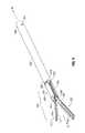
- FIG. 1is a side, perspective view of one embodiment of a forceps provided in accordance with the present disclosure, wherein jaw members of the forceps are disposed in a spaced-apart position;
- FIG. 2is a side, perspective view of the forceps of FIG. 1 , wherein the jaw members are disposed in an approximated position;
- FIG. 3is a side, perspective view of a proximal portion of the forceps of FIG. 1 , shown with parts separated;
- FIG. 4is a rear, perspective view of the forceps of FIG. 1 , shown with parts separated;
- FIG. 5is a front, perspective view of a shaft assembly of the forceps of FIG. 1 , shown with parts separated;
- FIG. 6is a front, perspective view of a distal end of the forceps of FIG. 1 ;
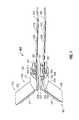
- FIG. 7is a rear, perspective view of an end effector assembly of the forceps of FIG. 1 ;
- FIG. 8Ais a front, perspective view of the jaw members of the forceps of FIG. 1 ;
- FIG. 8Bis an enlarged, front, perspective view of one of the jaw members of the forceps of FIG. 1 ;
- FIG. 8Cis a side view of the jaw member of FIG. 8B ;
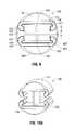
- FIG. 9is a front view of the end effector assembly of the forceps of FIG. 1 ;
- FIG. 10Ais a front, perspective view of another embodiment of an end effector assembly provided in accordance with the present disclosure and configured for use with the forceps of FIG. 1 ;
- FIG. 10Bis a front view of the end effector assembly of FIG. 10A shown including a pair of jaw members disposed therein.
- distalrefers to the portion that is being described which is further from a user
- proximalrefers to the portion that is being described which is closer to a user
- Forceps 10defines a longitudinal axis “X-X” and includes a handle assembly 100 , a plunger 200 extending proximally from handle assembly 100 , a shaft 300 extending distally from handle assembly 100 , and an end effector assembly 400 disposed at distal end 302 of shaft 300 .
- End effector assembly 400includes a pair of opposed jaw members 410 , 420 and a sliding unit 430 that is selectively translatable relative to jaw members 410 , 420 between a proximal position ( FIG. 1 ) and a distal position ( FIG.
- Plunger 200is translatable relative to handle assembly 100 between an extended or proximal position ( FIG. 1 ), wherein plunger 200 substantially extends proximally from handle assembly 100 , and an inserted or distal position ( FIG. 2 ), wherein plunger 200 is substantially disposed within handle assembly 100 , in order to translate shaft 300 between proximal and distal positions relative to handle assembly 100 .
- Translation of shaft 300 between the proximal and distal positionseffects translation of sliding unit 430 between the proximal and distal positions and, thus, transitions jaw members 410 , 420 between the spaced-apart position ( FIG. 1 ) and the approximated position ( FIG. 2 ).
- Forceps 10also includes an electrosurgical cable 500 extending from handle assembly 100 that is electrically coupled to jaw members 410 , 420 and is adapted to connect to a generator (not shown) or other suitable power source, although forceps 10 may alternatively be configured as a battery powered instrument. Cable 500 is configured to provide energy to at least one of jaw members 410 , 420 of end effector assembly 400 for treating tissue grasped therebetween, as will be described in greater detail below. Although the present disclosure is described with respect to electrical energy, it is contemplated that other types of energy may also be used in conjunction with forceps 10 , e.g., thermal energy, ultrasonic energy, light energy, etc.
- handle assembly 100is formed from first and second housing parts 110 , 120 that are engagable with one another to form handle assembly 100 . More specifically, each housing part 110 , 120 includes a plurality of posts 112 , 122 disposed on engaging surfaces 114 , 124 , respectively, thereof and extending therefrom. Housing part 110 includes a plurality of apertures (not shown) defined within engaging surface 114 thereof, and housing part 120 similarly includes a plurality of apertures 126 defined within engaging surface 124 thereof.
- Posts 112 of housing part 110are positioned to oppose apertures 126 of housing part 120 and, similarly, posts 122 of housing part 120 are positioned to oppose the apertures (not shown) of housing part 110 such that, upon approximation of housing parts 110 , 120 , posts 112 are engaged within apertures 126 and posts 122 are engaged within the apertures (not shown) defined within housing part 110 to engage first and second housing parts 110 , 120 , respectively, to one another.
- Each housing part 110 , 120further includes an elongated body portion 117 , 127 and an ergonomically-configured handle 118 , 128 extending outwardly therefrom.
- Each handle 118 , 128defines a finger hole 119 , 129 therethrough for receiving a finger of the user.
- finger holes 119 , 129facilitate grasping of handle assembly 100 during translation of plunger 200 relative to handle assembly 100 between the proximal and distal positions to transition jaw members 410 , 420 ( FIGS. 1-2 ) of end effector assembly 400 ( FIGS. 1-2 ) between the spaced-apart and approximated positions.
- body portions 117 , 127 of housing parts 110 , 120cooperate with one another to define a longitudinally-extending lumen 130 therethrough.
- Lumen 130is disposed about longitudinal axis “X-X” and is configured to permit reciprocation of plunger 200 through proximal portion 132 thereof, as plunger 200 is translated between the proximal and distal positions, and to permit reciprocation of shaft 300 through distal portion 134 thereof, as shaft 300 is translated between the proximal and distal positions to transition jaw members 410 , 420 ( FIGS. 1-2 ) between the spaced-apart and approximated positions.
- plunger 200is coupled to shaft 300 such that translation of plunger 200 along longitudinal axis “X-X” and relative to handle assembly 100 effects similar translation of shaft 300 along longitudinal axis “X-X” and relative to handle assembly 200 .
- Plunger 200generally includes a distal sleeve 210 , an elongated tubular member 220 extending from proximal end 212 of distal sleeve 210 , and a knob 230 disposed at proximal end 222 of elongated tubular member 220 .
- Knob 230is configured for single handed-used, e.g., where knob 230 is grasped, or palmed, by the palm of user, while the user grasps handle assembly 100 by engagement of the user's fingers within finger holes 119 , 129 of handles 118 , 128 , respectively, to facilitate translation of plunger 200 relative to handle assembly 100 , although outer grasping configurations, e.g., two-handed operation, are also contemplated.
- Distal sleeve 210may be formed from a first component 214 and a second component (not shown) substantially similar to first component 214 that, together, cooperate to define distal sleeve 210 .
- the second component (not shown)has been removed to show the internal components of distal sleeve 210 , although distal sleeve 210 may alternatively be configured with just one component 214 .
- Distal sleeve 210further includes a pair of opposed slots 215 , 216 defined therethrough. Slots 215 , 216 are configured to receive a tab (not shown) extending inwardly from the interior surface of housing part 110 and tab 142 extending inwardly from the interior surface of housing part 120 , respectively.
- the interior of housing part 110is not shown; however, the interior of housing part 110 is substantially similar to that of housing part 120 . Accordingly, the features and configuration of housing part 120 described and shown herein apply similarly to housing part 110 , except where specifically disclaimed.
- Tab 142 of housing part 120extends inwardly from the interior surface thereof and is configured to extend into slot 216 defined within distal sleeve 210 .
- tab 142 of housing part 120is configured to engage proximal end 422 of jaw member 420 thereon to retain jaw member 420 in fixed longitudinal position relative to handle assembly 100 .
- the tab (not shown) extending inwardly from housing part 110is configured to engage proximal end 412 of jaw member 410 to retain jaw member 410 in fixed longitudinal position relative to handle assembly 100 .
- tab (not shown) of housing part 110 and tab 142 of housing part 120may be engaged within elongated apertures 413 , 423 defined within jaw members 410 , 420 , respectively, towards respective proximal ends 412 , 422 thereof, although any other suitable engagement mechanism may be used.
- the range of translation of plunger 200 and, thus, shaft 300 , relative to handle assembly 100is defined by the length of slots 215 , 216 . More specifically, the proximal position of plunger 200 corresponds to the position wherein tab 142 of housing part 120 and the tab (not shown) of housing part 110 are disposed at distal ends 217 a , 218 a of slots 215 , 216 , respectively, thus inhibiting further proximal translation of plunger 200 , while the distal position of plunger 200 corresponds to the position wherein tab 142 of housing part 120 and the tab (not shown) of housing part 110 are disposed at proximal ends 217 b , 218 b of slots 215 , 216 , respectively, thus inhibiting further distal translation of plunger 200 .
- Tab 142 of housing part 120further includes a lumen 144 extending therethrough in transverse relation relative to longitudinal axis “X-X.”
- Lumen 144extends from tab 142 completely through housing part 120 and is configured to receive cable 500 ( FIGS. 1-2 ) therethrough. More specifically, cable 500 extends through lumen 144 of housing part 120 into handle assembly 100 , ultimately electrically coupling to proximal end 422 of jaw member 420 (and/or proximal end 412 of jaw member 410 ), which is engaged to tab 142 of housing part 120 .
- energymay be supplied from an energy source (not shown) via cable 500 to jaw member 410 .
- a lumen (not shown)may be defined within the tab (not shown) of housing part 110 to permit passage of a cable (not shown) therethrough for coupling jaw member 410 to the energy source (not shown).
- plunger 200is coupled to shaft 300 such that translation of plunger 200 along longitudinal axis “X-X” effects similar translation of shaft 300 along longitudinal axis “X-X.”
- shaft 300includes a pair of recesses 304 defined within opposed lateral sides of shaft 300 at proximal end 306 thereof that are configured to receive protrusions 240 extending inwardly from distal sleeve 210 of plunger 200 to engage plunger 200 and shaft 300 to one another on either side of shaft 300 .
- plunger 200 and shaft 300may be formed monolithically as a single component that includes slots 215 , 216 defined therethrough to permit engagement of jaw members 410 , 420 and handle assembly 100 to one another.
- Shaft 300defines an elongated, generally cylindrical configuration having a distal end 302 and a proximal end 306 and defining a plurality of lumens extending at least partially therethrough.
- First and second opposed lumens 310 , 320are symmetrically disposed on either side of longitudinal axis “X-X” and extend completely through shaft 300 .
- First and second lumens 310 , 320are configured to receive proximal portions 414 , 424 of jaw members 410 , 420 , respectively, therethrough.
- Lumens 310 , 320are configured such that shaft 300 is selectively translatable relative to jaw members 410 , 420 between the proximal and distal positions, i.e., such that jaw members 410 , 420 are translatable through lumens 310 , 320 , respectively, of shaft 300 .
- Third and fourth opposed lumens 330 , 340are symmetrically disposed on either side of longitudinal axis “X-X” and are positioned farther-apart from one another as compared to first and second lumens 310 , 320 , i.e., lumens 330 , 340 are defined towards the outer periphery of shaft 300 , while first and second lumens 310 , 320 , are more-inwardly disposed.
- Third and fourth lumens 330 , 340extend partially through shaft 300 from distal end 302 thereof and are configured to engage proximal ends 442 , 452 of support bars 440 , 450 , respectively, of end effector assembly 400 therein, e.g., in friction-fit engagement therewith.
- Distal ends 444 , 454 of support bars 440 , 450are configured for engagement within lumens 432 defined within first and second components 431 , 436 of sliding unit 430 .
- shaft 300 and sliding unit 430 of end effector assembly 400are engaged to one another via support bars 440 , 450 such that translation of shaft 300 effects similar translation of sliding unit 430 .
- sliding unit 430is formed from an electrically-insulative material and includes first and second components 431 , 436 , respectively, that each define opposed, hemispherical configurations, although other configurations are contemplated.
- First and second components 431 , 436 of sliding unit 430engage distal ends 444 , 454 of support bars 440 , 450 , respectively, within lumens 432 thereof.
- First and second components 431 , 436 of sliding unit 430each further include a track 433 , 437 , respectively, defined longitudinally therethrough.
- Tracks 433 , 437each include a first track section 434 , 438 , configured to receive jaw members 410 , 420 , respectively, therethrough, and a second track section 435 , 439 , configured to receive sealing plates 417 , 427 , respectively, therethrough upon translation of sliding unit 430 to the distal position to approximate jaw members 410 , 420 .
- Jaw members 410 , 420 of end effector assembly 400each define an elongated, generally flat, rectangular configuration permitting jaw members 410 , 420 to extend completely through shaft 300 and into engagement with handle assembly 100 ( FIGS. 1-2 ). More specifically, jaw members 410 , 420 each include a proximal segment 414 , 424 that extends through shaft 300 and into handle assembly 100 ( FIGS. 1-2 ), a flexible intermediate segment 415 , 425 , and a distal segment 416 , 426 , respectively, that retains sealing plates 417 , 427 , respectively, thereon. Further, jaw members 410 , 420 are formed at least partially from an electrically-conductive material such that energy supplied by cable 500 ( FIGS.
- jaw members 410 , 420may be configured as electrodes 410 , 420 , respectively.
- flexible intermediate segments 415 , 425 , of jaw members 410 , 420are formed as flat-springs (or any other suitable biasing members) that are biased-apart from one another such that, as shown in FIG. 6 , jaw members 410 , 420 are disposed in the spaced-apart position when sliding component 430 is disposed in the proximal position.
- jaw members 410 , 420are brought into approximation with one another, against the bias of intermediate segments 415 , 425 , due to the increasing engagement of jaw members 410 , 420 within first track sections 434 , 438 of tracks 433 , 437 , respectively, of sliding component 430 .
- jaw members 410 , 420each include an electrically-conductive tissue sealing plate 417 , 427 , respectively, disposed thereon in opposed relation relative to one another.
- Tissue sealing plates 417 , 427may be engaged on distal segments 416 , 426 of jaw members 410 , 420 , respectively, in any suitable fashion, e.g., welding, adhesion, etc., or may be monolithically formed therewith.
- Tissue sealing plates 417 , 427are configured to grasp tissue therebetween upon approximation of jaw members 410 , 420 and are electrically coupled to jaw members 410 , 420 such that energy may be conducted between tissue sealing plates 417 , 427 and through tissue grasped therebetween to effect a tissue seal.
- the electrically-conductive tissue sealing plates 417 , 427may be disposed in contact with respective electrically-conductive jaw members 410 , 420 such that electrical energy may be transmitted therebetween, although any other suitable electrical connection may also be provided.
- jaw member 410 and/or jaw member 420may also include a longitudinally-extending knife channel 418 , 428 , respectively, defined therethrough that is configured to permit reciprocation of a knife 700 ( FIGS. 10A-10B ) therethrough to cut tissue grasped between jaw members 410 , 420 , e.g., to cut sealed tissue along the tissue seal.
- Tissue sealing plates 417 , 427 of jaw members 410 , 420 , respectively, as shown in FIGS. 5-8Cmay also include textured tissue-grasping surfaces 419 , 429 , respectively, to facilitate the grasping and retention of tissue therebetween as jaw members 410 , 420 are moved from the spaced-apart position to the approximated position. More specifically, tissue sealing plates 417 , 427 of jaw members 410 , 420 , respectively, may include serrations, protrusions, or other suitable surface features defined on tissue-grasping surfaces 419 , 429 , respectively, thereof, that are configured to facilitate the grasping and retention of tissue therebetween without damaging tissue.
- end effector assembly 400is shown wherein sliding unit 430 is disposed in the distal position substantially surrounding distal segments 416 , 426 of respective jaw members 410 , 420 such that jaw members 410 , 420 are disposed in the approximated position. More specifically, in this position, jaw members 410 , 420 are disposed within first track sections 434 , 438 , of first and second components 431 , 436 , respectively, of sliding unit 430 , while sealing plates 417 , 427 are disposed within second track section 435 , 439 of first and second components 431 , 436 , respectively, of sliding unit 430 .
- tissue sealing plates 417 , 427extend from respective components 431 , 436 of sliding unit 430 toward one another to define a minimum gap distance “G” therebetween.
- Gap distances “G” in the range of about 0.001 inches to about 0.006 inchesare contemplated, although sliding unit 430 may be configured to achieve other suitable gap distances “G.”
- sliding unit 730is substantially similar to sliding unit 430 ( FIGS. 1-2 ) except that sliding unit 730 includes a knife 700 disposed therein and extending between first and second components 731 , 736 , respectively, of sliding unit 730 .
- knife 700is simultaneously advanced distally through knife channels 418 , 428 defined within tissue sealing plates 417 , 427 of jaw members 410 , 420 , respectively, to cut tissue grasped therebetween.
- knife 700may be configured for selectively translation, independent of sliding unit 730 , to cut tissue grasped between jaw members 410 , 420 .
- plunger 200is disposed in the proximal position, wherein plunger 200 extends proximally from handle assembly 100 .
- shaft 300 and sliding unit 430are likewise disposed in their respective proximal positions such that jaw members 410 , 420 of end effector assembly 400 extend distally from sliding unit 430 and are disposed in the spaced-apart position under the bias of intermediate segments 415 , 425 , respectively.
- forceps 10With forceps 10 disposed in this position, forceps 10 may be maneuvered and/or manipulated into position within a surgical site such that tissue to be grasped, sealed, and/or divided is disposed between tissue sealing plates 417 , 427 of jaw members 410 , 420 , respectively.
- jaw members 410 , 420may be transitioned to the approximated position to grasp tissue therebetween. More specifically, in order to transition jaw members 410 , 420 from the spaced-apart position, to the approximated position, the user grasps handles 118 , 128 of handle assembly 100 with the user's hand, e.g., via inserting one or more fingers through each of finger holes 119 , 129 , and palms, or grasps knob 230 of plunger 200 with the palm of the same hand (or the thumb thereof). Alternatively, the user may grasp handles 118 , 128 with one hand, while grasping knob 230 with other hand. Other suitable configurations may also be used, depending on the user's preference.
- jaw members 410 , 420 and tissue sealing plates 417 , 427are translated into and through first and second track sections 434 , 438 and 435 , 439 , respectively, of first and second components 431 , 436 , respectively, of sliding unit 430 , such that jaw members 410 , 420 are brought into approximation with one another to grasp tissue therebetween.
- the surface feature(s) of tissue sealing plates 417 , 427may facilitate the grasping of tissue therebetween as jaw members 410 , 420 are flexed from the biased, spaced-apart position, towards the approximated position.
- tissue sealing plates 417 , 427 of jaw members 410 , 420After, or simultaneously with, the grasping of tissue between tissue sealing plates 417 , 427 of jaw members 410 , 420 , respectively, energy may be supplied to one or both of tissue sealing plates 417 , 427 of jaw members 410 , 420 , respectively, e.g., via cable 500 , to seal tissue grasped therebetween.
- the creation of an effective tissue sealis facilitated by the maintenance of the minimum gap distance “G” ( FIG. 9 ) between tissue sealing plates 417 , 427 when jaw members 410 , 420 are disposed in the approximated position.
- the insulative sliding unit 430which is disposed about jaw members 410 , 420 and tissue sealing plates 417 , 427 when in the distal position, inhibits thermal damage to surrounding tissue as the tissue sealing plates 417 , 427 are energized during tissue sealing.
- tissueis cut, or divided simultaneously, or near simultaneously with the grasping and sealing of tissue. More specifically, as sliding unit 730 is advanced over jaw members 410 , 420 to transition jaw members 410 , 420 to the approximated position, energy is supplied to one or both of tissue sealing plates 417 , 427 of jaw members 410 , 420 , respectively, e.g., via cable 500 , to seal tissue grasped therebetween, while knife 700 is advanced through knife channels 418 , 428 of jaw members 410 , 420 , respectively, to cut tissue along the tissue seal.
- sealing of tissueneed not necessarily be performed, as sliding unit 730 may simply be advanced over jaw members 410 , 420 to grasp and divide tissue disposed therebetween.
- knob 230 of plunger 200may be translated proximally relative to handle assembly 100 back to the proximal position such that shaft 300 and sliding unit 430 are returned back to their respective proximal positions, thus allowing jaw members 410 , 420 to return, under the bias of intermediate segments 415 , 425 , respectively, back to the spaced-apart position to release the sealed and/or divided tissue.
- forceps 10may be removed from the surgical site.
Landscapes
- Health & Medical Sciences (AREA)
- Surgery (AREA)
- Engineering & Computer Science (AREA)
- Life Sciences & Earth Sciences (AREA)
- Biomedical Technology (AREA)
- Otolaryngology (AREA)
- Nuclear Medicine, Radiotherapy & Molecular Imaging (AREA)
- Plasma & Fusion (AREA)
- Physics & Mathematics (AREA)
- Heart & Thoracic Surgery (AREA)
- Medical Informatics (AREA)
- Molecular Biology (AREA)
- Animal Behavior & Ethology (AREA)
- General Health & Medical Sciences (AREA)
- Public Health (AREA)
- Veterinary Medicine (AREA)
- Surgical Instruments (AREA)
Abstract
Description
Claims (16)
Priority Applications (1)
| Application Number | Priority Date | Filing Date | Title |
|---|---|---|---|
| US13/223,521US9113909B2 (en) | 2011-09-01 | 2011-09-01 | Surgical vessel sealer and divider |
Applications Claiming Priority (1)
| Application Number | Priority Date | Filing Date | Title |
|---|---|---|---|
| US13/223,521US9113909B2 (en) | 2011-09-01 | 2011-09-01 | Surgical vessel sealer and divider |
Publications (2)
| Publication Number | Publication Date |
|---|---|
| US20130060250A1 US20130060250A1 (en) | 2013-03-07 |
| US9113909B2true US9113909B2 (en) | 2015-08-25 |
Family
ID=47753707
Family Applications (1)
| Application Number | Title | Priority Date | Filing Date |
|---|---|---|---|
| US13/223,521Expired - Fee RelatedUS9113909B2 (en) | 2011-09-01 | 2011-09-01 | Surgical vessel sealer and divider |
Country Status (1)
| Country | Link |
|---|---|
| US (1) | US9113909B2 (en) |
Cited By (25)
| Publication number | Priority date | Publication date | Assignee | Title |
|---|---|---|---|---|
| US9610121B2 (en) | 2012-03-26 | 2017-04-04 | Covidien Lp | Light energy sealing, cutting and sensing surgical device |
| US9861378B2 (en) | 2012-05-01 | 2018-01-09 | Covidien Lp | Surgical instrument with stamped double-flange jaws |
| US9877777B2 (en) | 2014-09-17 | 2018-01-30 | Covidien Lp | Surgical instrument having a bipolar end effector assembly and a deployable monopolar assembly |
| US9918785B2 (en) | 2014-09-17 | 2018-03-20 | Covidien Lp | Deployment mechanisms for surgical instruments |
| US9931158B2 (en) | 2014-09-17 | 2018-04-03 | Covidien Lp | Deployment mechanisms for surgical instruments |
| US9931131B2 (en) | 2009-09-18 | 2018-04-03 | Covidien Lp | In vivo attachable and detachable end effector assembly and laparoscopic surgical instrument and methods therefor |
| US9987076B2 (en) | 2014-09-17 | 2018-06-05 | Covidien Lp | Multi-function surgical instruments |
| US10080605B2 (en) | 2014-09-17 | 2018-09-25 | Covidien Lp | Deployment mechanisms for surgical instruments |
| US10172612B2 (en) | 2015-01-21 | 2019-01-08 | Covidien Lp | Surgical instruments with force applier and methods of use |
| US10188454B2 (en) | 2009-09-28 | 2019-01-29 | Covidien Lp | System for manufacturing electrosurgical seal plates |
| USD844138S1 (en) | 2015-07-17 | 2019-03-26 | Covidien Lp | Handle assembly of a multi-function surgical instrument |
| USD844139S1 (en) | 2015-07-17 | 2019-03-26 | Covidien Lp | Monopolar assembly of a multi-function surgical instrument |
| US10251696B2 (en) | 2001-04-06 | 2019-04-09 | Covidien Ag | Vessel sealer and divider with stop members |
| US10271897B2 (en) | 2012-05-01 | 2019-04-30 | Covidien Lp | Surgical instrument with stamped double-flange jaws and actuation mechanism |
| US10537381B2 (en) | 2016-02-26 | 2020-01-21 | Covidien Lp | Surgical instrument having a bipolar end effector assembly and a deployable monopolar assembly |
| US10639095B2 (en) | 2012-01-25 | 2020-05-05 | Covidien Lp | Surgical instrument with resilient driving member and related methods of use |
| US10813695B2 (en) | 2017-01-27 | 2020-10-27 | Covidien Lp | Reflectors for optical-based vessel sealing |
| US10828756B2 (en) | 2018-04-24 | 2020-11-10 | Covidien Lp | Disassembly methods facilitating reprocessing of multi-function surgical instruments |
| US11123132B2 (en) | 2018-04-09 | 2021-09-21 | Covidien Lp | Multi-function surgical instruments and assemblies therefor |
| US11154348B2 (en) | 2017-08-29 | 2021-10-26 | Covidien Lp | Surgical instruments and methods of assembling surgical instruments |
| US11241275B2 (en) | 2018-03-21 | 2022-02-08 | Covidien Lp | Energy-based surgical instrument having multiple operational configurations |
| US11707313B2 (en) | 2012-03-29 | 2023-07-25 | Covidien Lp | Electrosurgical forceps and method of manufacturing the same |
| US11925406B2 (en) | 2020-09-14 | 2024-03-12 | Covidien Lp | End effector assemblies for surgical instruments |
| US12161386B2 (en) | 2020-09-11 | 2024-12-10 | Covidien Lp | Surgical instruments having an articulating section such as for use in robotic surgical systems |
| US12185964B2 (en) | 2020-09-10 | 2025-01-07 | Covidien Lp | End effector assemblies for surgical instruments such as for use in robotic surgical systems |
Families Citing this family (39)
| Publication number | Priority date | Publication date | Assignee | Title |
|---|---|---|---|---|
| US7364577B2 (en) | 2002-02-11 | 2008-04-29 | Sherwood Services Ag | Vessel sealing system |
| US7628791B2 (en) | 2005-08-19 | 2009-12-08 | Covidien Ag | Single action tissue sealer |
| US8298232B2 (en) | 2006-01-24 | 2012-10-30 | Tyco Healthcare Group Lp | Endoscopic vessel sealer and divider for large tissue structures |
| US8114122B2 (en) | 2009-01-13 | 2012-02-14 | Tyco Healthcare Group Lp | Apparatus, system, and method for performing an electrosurgical procedure |
| US8187273B2 (en) | 2009-05-07 | 2012-05-29 | Tyco Healthcare Group Lp | Apparatus, system, and method for performing an electrosurgical procedure |
| US9649120B1 (en)* | 2009-08-18 | 2017-05-16 | University Of South Florida | Minimally invasive surgery platform attachment apparatus |
| US8430876B2 (en) | 2009-08-27 | 2013-04-30 | Tyco Healthcare Group Lp | Vessel sealer and divider with knife lockout |
| US8864795B2 (en) | 2011-10-03 | 2014-10-21 | Covidien Lp | Surgical forceps |
| US8968309B2 (en) | 2011-11-10 | 2015-03-03 | Covidien Lp | Surgical forceps |
| US8968310B2 (en) | 2011-11-30 | 2015-03-03 | Covidien Lp | Electrosurgical instrument with a knife blade lockout mechanism |
| US8747434B2 (en) | 2012-02-20 | 2014-06-10 | Covidien Lp | Knife deployment mechanisms for surgical forceps |
| US8961514B2 (en)* | 2012-03-06 | 2015-02-24 | Covidien Lp | Articulating surgical apparatus |
| US9668807B2 (en) | 2012-05-01 | 2017-06-06 | Covidien Lp | Simplified spring load mechanism for delivering shaft force of a surgical instrument |
| US9039731B2 (en) | 2012-05-08 | 2015-05-26 | Covidien Lp | Surgical forceps including blade safety mechanism |
| US9375258B2 (en) | 2012-05-08 | 2016-06-28 | Covidien Lp | Surgical forceps |
| US9265566B2 (en) | 2012-10-16 | 2016-02-23 | Covidien Lp | Surgical instrument |
| US20150005759A1 (en) | 2013-03-14 | 2015-01-01 | Cynosure, Inc. | Current Delivery Systems, Apparatuses and Methods |
| USD788302S1 (en) | 2013-10-01 | 2017-05-30 | Covidien Lp | Knife for endoscopic electrosurgical forceps |
| JP5855684B2 (en)* | 2014-01-16 | 2016-02-09 | オリンパス株式会社 | Energy treatment tool |
| US10499977B2 (en)* | 2014-08-11 | 2019-12-10 | Covidien Lp | Surgical instruments and methods for performing tonsillectomy and adenoidectomy procedures |
| CN106999202B (en)* | 2014-09-25 | 2019-11-15 | 柯惠有限合伙公司 | The surgical instruments of extensible length |
| US12090076B2 (en)* | 2016-05-31 | 2024-09-17 | Boston Scientific Scimed, Inc. | Devices and related methods for gastrectomies |
| US10959731B2 (en)* | 2016-06-14 | 2021-03-30 | Covidien Lp | Buttress attachment for surgical stapling instrument |
| US10631887B2 (en) | 2016-08-15 | 2020-04-28 | Covidien Lp | Electrosurgical forceps for video assisted thoracoscopic surgery and other surgical procedures |
| US10973567B2 (en) | 2017-05-12 | 2021-04-13 | Covidien Lp | Electrosurgical forceps for grasping, treating, and/or dividing tissue |
| US11172980B2 (en) | 2017-05-12 | 2021-11-16 | Covidien Lp | Electrosurgical forceps for grasping, treating, and/or dividing tissue |
| USD854149S1 (en) | 2017-06-08 | 2019-07-16 | Covidien Lp | End effector for open vessel sealer |
| USD843574S1 (en) | 2017-06-08 | 2019-03-19 | Covidien Lp | Knife for open vessel sealer |
| USD854684S1 (en) | 2017-06-08 | 2019-07-23 | Covidien Lp | Open vessel sealer with mechanical cutter |
| US10780544B2 (en) | 2018-04-24 | 2020-09-22 | Covidien Lp | Systems and methods facilitating reprocessing of surgical instruments |
| US11717338B2 (en)* | 2018-09-10 | 2023-08-08 | Jgmg Bengochea, Llc | Bipolar dissector |
| US11376062B2 (en) | 2018-10-12 | 2022-07-05 | Covidien Lp | Electrosurgical forceps |
| US11471211B2 (en) | 2018-10-12 | 2022-10-18 | Covidien Lp | Electrosurgical forceps |
| US11350982B2 (en) | 2018-12-05 | 2022-06-07 | Covidien Lp | Electrosurgical forceps |
| US11523861B2 (en) | 2019-03-22 | 2022-12-13 | Covidien Lp | Methods for manufacturing a jaw assembly for an electrosurgical forceps |
| US12402934B2 (en) | 2019-09-15 | 2025-09-02 | Covidien Lp | Electrosurgical instrument for grasping, treating, and/or dividing tissue incorporating thermal management feature |
| US11622804B2 (en) | 2020-03-16 | 2023-04-11 | Covidien Lp | Forceps with linear trigger mechanism |
| US12295641B2 (en) | 2020-07-01 | 2025-05-13 | Covidien Lp | Electrosurgical forceps with swivel action nerve probe |
| US11660109B2 (en) | 2020-09-08 | 2023-05-30 | Covidien Lp | Cutting elements for surgical instruments such as for use in robotic surgical systems |
Citations (134)
| Publication number | Priority date | Publication date | Assignee | Title |
|---|---|---|---|---|
| SU401367A1 (en) | 1971-10-05 | 1973-10-12 | Тернопольский государственный медицинский институт | BIAKTIVNYE ELECTRO SURGICAL INSTRUMENT |
| DE2415263A1 (en) | 1974-03-29 | 1975-10-02 | Aesculap Werke Ag | Surgical H.F. coagulation probe has electrode tongs - with exposed ends of insulated conductors forming tong-jaws |
| DE2514501A1 (en) | 1975-04-03 | 1976-10-21 | Karl Storz | Bipolar coagulation instrument for endoscopes - has two high frequency electrodes looped over central insulating piece |
| DE2627679A1 (en) | 1975-06-26 | 1977-01-13 | Marcel Lamidey | HEMATISTIC HIGH FREQUENCY EXTRACTOR FORCEPS |
| USD249549S (en) | 1976-10-22 | 1978-09-19 | Aspen Laboratories, Inc. | Electrosurgical handle |
| USD263020S (en) | 1980-01-22 | 1982-02-16 | Rau Iii David M | Retractable knife |
| DE3423356A1 (en) | 1984-06-25 | 1986-01-02 | Berchtold Medizin-Elektronik GmbH & Co, 7200 Tuttlingen | ELECTROSURGICAL HIGH-FREQUENCY CUTTING INSTRUMENT |
| JPS61501068A (en) | 1984-01-30 | 1986-05-29 | ハルコフスキイ ナウチノ−イススレドワテルスキイ インスチチユ−ト オブスチエイ イ ネオトロジノイ ヒルルギイ | bipolar electrosurgical instrument |
| DE3612646A1 (en) | 1985-04-16 | 1987-04-30 | Ellman International | Electrosurgical handle piece for blades, needles and forceps |
| DE8712328U1 (en) | 1987-09-11 | 1988-02-18 | Jakoubek, Franz, 7201 Emmingen-Liptingen | Endoscopy forceps |
| USD295894S (en) | 1985-09-26 | 1988-05-24 | Acme United Corporation | Disposable surgical scissors |
| USD295893S (en) | 1985-09-25 | 1988-05-24 | Acme United Corporation | Disposable surgical clamp |
| USD298353S (en) | 1986-05-06 | 1988-11-01 | Vitalmetrics, Inc. | Handle for surgical instrument |
| USD299413S (en) | 1985-07-17 | 1989-01-17 | The Stanley Works | Folding pocket saw handle |
| JPH055106A (en) | 1990-07-31 | 1993-01-14 | Matsushita Electric Works Ltd | Production of alloy sintered body |
| JPH0540112A (en) | 1991-02-08 | 1993-02-19 | Tokico Ltd | Sample liquid component analyzer |
| USD343453S (en) | 1993-05-05 | 1994-01-18 | Laparomed Corporation | Handle for laparoscopic surgical instrument |
| JPH0630945A (en) | 1992-05-19 | 1994-02-08 | Olympus Optical Co Ltd | Suturing apparatus |
| JPH06502328A (en) | 1990-10-17 | 1994-03-17 | ボストン サイエンティフィック コーポレイション | Surgical instruments and methods |
| JPH06121797A (en) | 1992-02-27 | 1994-05-06 | United States Surgical Corp | Equipment and method for performing intracutaneous stapling of body tissue |
| USD348930S (en) | 1991-10-11 | 1994-07-19 | Ethicon, Inc. | Endoscopic stapler |
| USD349341S (en) | 1992-10-28 | 1994-08-02 | Microsurge, Inc. | Endoscopic grasper |
| DE4303882A1 (en) | 1993-02-10 | 1994-08-18 | Kernforschungsz Karlsruhe | Combined instrument for separating and coagulating in minimally invasive surgery |
| JPH06285078A (en) | 1993-04-05 | 1994-10-11 | Olympus Optical Co Ltd | Forceps |
| JPH06343644A (en) | 1993-05-04 | 1994-12-20 | Gyrus Medical Ltd | Surgical peritoneoscope equipment |
| JPH06511401A (en) | 1991-06-07 | 1994-12-22 | バイタル メディカル プロダクツ コーポレイション | Bipolar electrosurgical endoscopic instrument and its method of use |
| USD354564S (en) | 1993-06-25 | 1995-01-17 | Richard-Allan Medical Industries, Inc. | Surgical clip applier |
| USD358887S (en) | 1993-12-02 | 1995-05-30 | Cobot Medical Corporation | Combined cutting and coagulating forceps |
| DE4403252A1 (en) | 1994-02-03 | 1995-08-10 | Michael Hauser | Instrument shaft for min. invasive surgery |
| JPH07265328A (en) | 1993-11-01 | 1995-10-17 | Gyrus Medical Ltd | Electrode assembly for electric surgery device and electric surgery device using it |
| JPH0856955A (en) | 1994-06-29 | 1996-03-05 | Gyrus Medical Ltd | Electric surgical apparatus |
| DE19515914C1 (en) | 1995-05-02 | 1996-07-25 | Aesculap Ag | Tong or scissor-shaped surgical instrument |
| DE19506363A1 (en) | 1995-02-24 | 1996-08-29 | Frost Lore Geb Haupt | Non-invasive thermometry in organs under hyperthermia and coagulation conditions |
| JPH08252263A (en) | 1994-12-21 | 1996-10-01 | Gyrus Medical Ltd | Electronic surgical incision instrument and electronic surgical incision device using the same |
| JPH08289895A (en) | 1995-04-21 | 1996-11-05 | Olympus Optical Co Ltd | Suture device |
| DE29616210U1 (en) | 1996-09-18 | 1996-11-14 | Olympus Winter & Ibe Gmbh, 22045 Hamburg | Handle for surgical instruments |
| JPH08317936A (en) | 1995-01-18 | 1996-12-03 | Ethicon Endo Surgery Inc | Hemostatic device for electric surgery provided with recessed type and/or crossed type electrode |
| JPH08317934A (en) | 1995-04-12 | 1996-12-03 | Ethicon Endo Surgery Inc | Hemostatic device for electric surgery with adaptable electrode |
| JPH0910223A (en) | 1995-06-23 | 1997-01-14 | Gyrus Medical Ltd | Generator and system for electric operation |
| DE19608716C1 (en) | 1996-03-06 | 1997-04-17 | Aesculap Ag | Bipolar surgical holding instrument |
| JPH09122138A (en) | 1995-10-20 | 1997-05-13 | Ethicon Endo Surgery Inc | Apparatus for operation |
| USD384413S (en) | 1994-10-07 | 1997-09-30 | United States Surgical Corporation | Endoscopic suturing instrument |
| JPH1024051A (en) | 1995-09-20 | 1998-01-27 | Olympus Optical Co Ltd | Coagulation forceps with separating function |
| DE19751106A1 (en) | 1996-11-27 | 1998-05-28 | Eastman Kodak Co | Laser printer with array of laser diodes |
| JPH10155798A (en) | 1996-12-04 | 1998-06-16 | Asahi Optical Co Ltd | Hot biopsy forceps for endoscopes |
| USH1745H (en) | 1995-09-29 | 1998-08-04 | Paraschac; Joseph F. | Electrosurgical clamping device with insulation limited bipolar electrode |
| US5797958A (en) | 1989-12-05 | 1998-08-25 | Yoon; Inbae | Endoscopic grasping instrument with scissors |
| USD402028S (en) | 1997-10-10 | 1998-12-01 | Invasatec, Inc. | Hand controller for medical system |
| JPH1147150A (en) | 1997-08-06 | 1999-02-23 | Olympus Optical Co Ltd | Endoscopic surgery appliance |
| DE19738457A1 (en) | 1997-09-03 | 1999-03-04 | Laser & Med Tech Gmbh | Method for in-vivo depth coagulation of biological tissue |
| JPH1170124A (en) | 1997-05-14 | 1999-03-16 | Ethicon Endo Surgery Inc | Improved electrosurgical hemostatic apparatus having anvil |
| USD408018S (en) | 1996-03-12 | 1999-04-13 | Mcnaughton Patrick J | Switch guard |
| DE19751108A1 (en) | 1997-11-18 | 1999-05-20 | Beger Frank Michael Dipl Desig | Electrosurgical operation tool, especially for diathermy |
| JPH11169381A (en) | 1997-12-15 | 1999-06-29 | Olympus Optical Co Ltd | High frequency treating device |
| JPH11192238A (en) | 1997-10-10 | 1999-07-21 | Ethicon Endo Surgery Inc | Ultrasonic forceps coagulation device improved of pivot-attaching of forceps arm |
| JPH11244298A (en) | 1997-12-19 | 1999-09-14 | Gyrus Medical Ltd | Electric surgical instrument |
| USD416089S (en) | 1996-04-08 | 1999-11-02 | Richard-Allan Medical Industries, Inc. | Endoscopic linear stapling and dividing surgical instrument |
| US5984939A (en)* | 1989-12-05 | 1999-11-16 | Yoon; Inbae | Multifunctional grasping instrument with cutting member and operating channel for use in endoscopic and non-endoscopic procedures |
| US5993466A (en)* | 1997-06-17 | 1999-11-30 | Yoon; Inbae | Suturing instrument with multiple rotatably mounted spreadable needle holders |
| JP2000102545A (en) | 1997-06-18 | 2000-04-11 | Eggers & Associates Inc | Electric tweezers for surgery |
| USD424694S (en) | 1998-10-23 | 2000-05-09 | Sherwood Services Ag | Forceps |
| USD425201S (en) | 1998-10-23 | 2000-05-16 | Sherwood Services Ag | Disposable electrode assembly |
| US6074389A (en)* | 1995-03-10 | 2000-06-13 | Seedling Enterprises, Llc | Electrosurgery with cooled electrodes |
| WO2000036986A1 (en) | 1998-12-18 | 2000-06-29 | Karl Storz Gmbh & Co. Kg | Bipolar medical instrument |
| USH1904H (en) | 1997-05-14 | 2000-10-03 | Ethicon Endo-Surgery, Inc. | Electrosurgical hemostatic method and device |
| WO2000059392A1 (en) | 1999-04-01 | 2000-10-12 | Erbe Elektromedizin | Surgical instrument |
| JP2000342599A (en) | 1999-05-21 | 2000-12-12 | Gyrus Medical Ltd | Generator for electrosurgical operation, electrosurgical operation system, method for operating this system and method for performing amputation and resection of tissue by electrosurgical operation |
| JP2000350732A (en) | 1999-05-21 | 2000-12-19 | Gyrus Medical Ltd | Electrosurgical system, generator for electrosurgery, and method for cutting or excising tissue by electrosurgery |
| JP2001003400A (en) | 1999-06-21 | 2001-01-09 | Sumitomo Constr Mach Co Ltd | Monitor device for hydraulic shovel |
| JP2001008944A (en) | 1999-05-28 | 2001-01-16 | Gyrus Medical Ltd | Electric surgical signal generator and electric surgical system |
| JP2001029356A (en) | 1999-06-11 | 2001-02-06 | Gyrus Medical Ltd | Electric and surgical signal generator |
| WO2001015614A1 (en) | 1999-08-27 | 2001-03-08 | Karl Storz Gmbh & Co. Kg | Bipolar medical instrument |
| JP2001128990A (en) | 1999-05-28 | 2001-05-15 | Gyrus Medical Ltd | Electro surgical instrument and electrosurgical tool converter |
| DE19946527C1 (en) | 1999-09-28 | 2001-07-12 | Storz Karl Gmbh & Co Kg | Bipolar, e.g. laparoscopic surgery instrument, cuts electrically, cauterizes and grips using simple design with high frequency current-concentrating projections |
| JP2001190564A (en) | 2000-01-12 | 2001-07-17 | Olympus Optical Co Ltd | Medical treatment instrument |
| WO2001054604A1 (en) | 2000-01-25 | 2001-08-02 | Aesculap Ag & Co. Kg | Bipolar gripping device |
| US6273887B1 (en) | 1998-01-23 | 2001-08-14 | Olympus Optical Co., Ltd. | High-frequency treatment tool |
| USD449886S1 (en) | 1998-10-23 | 2001-10-30 | Sherwood Services Ag | Forceps with disposable electrode |
| EP1159926A2 (en) | 2000-06-03 | 2001-12-05 | Aesculap Ag | Scissor- or forceps-like surgical instrument |
| USD453923S1 (en) | 2000-11-16 | 2002-02-26 | Carling Technologies, Inc. | Electrical rocker switch guard |
| USD454951S1 (en) | 2001-02-27 | 2002-03-26 | Visionary Biomedical, Inc. | Steerable catheter |
| DE10045375A1 (en) | 2000-09-14 | 2002-04-11 | Aesculap Ag & Co Kg | Medical instrument comprises temperature and pressure condition sensor and modification device for influencing transmitting device |
| USD457959S1 (en) | 2001-04-06 | 2002-05-28 | Sherwood Services Ag | Vessel sealer |
| USD457958S1 (en) | 2001-04-06 | 2002-05-28 | Sherwood Services Ag | Vessel sealer and divider |
| US6419675B1 (en) | 1999-09-03 | 2002-07-16 | Conmed Corporation | Electrosurgical coagulating and cutting instrument |
| US6419640B1 (en)* | 2000-10-03 | 2002-07-16 | Thomas V. Taylor | Multiple-specimen, endoscopic biopsy forceps |
| JP2002528166A (en) | 1998-10-23 | 2002-09-03 | シャーウッド サーヴィシス アクチェンゲゼルシャフト | Externally-opened vascular sealing forceps with disposable electrodes |
| US6464702B2 (en) | 2001-01-24 | 2002-10-15 | Ethicon, Inc. | Electrosurgical instrument with closing tube for conducting RF energy and moving jaws |
| USD465281S1 (en) | 1999-09-21 | 2002-11-05 | Karl Storz Gmbh & Co. Kg | Endoscopic medical instrument |
| USD466209S1 (en) | 2001-02-27 | 2002-11-26 | Visionary Biomedical, Inc. | Steerable catheter |
| JP2003245285A (en) | 2002-01-23 | 2003-09-02 | Ethicon Endo Surgery Inc | Feedback light apparatus and method for use with electrosurgical instrument |
| US6652521B2 (en) | 2001-01-24 | 2003-11-25 | Ethicon, Inc. | Surgical instrument with a bi-directional cutting element |
| JP2004517668A (en) | 2000-10-20 | 2004-06-17 | オーナックス・メディカル・インコーポレーテッド | Surgical suturing instrument and method of use |
| USD493888S1 (en) | 2003-02-04 | 2004-08-03 | Sherwood Services Ag | Electrosurgical pencil with pistol grip |
| JP2004528869A (en) | 2001-01-26 | 2004-09-24 | エシコン・エンド−サージェリィ・インコーポレイテッド | Electrosurgical instruments for coagulation and cutting |
| USD496997S1 (en) | 2003-05-15 | 2004-10-05 | Sherwood Services Ag | Vessel sealer and divider |
| USD499181S1 (en) | 2003-05-15 | 2004-11-30 | Sherwood Services Ag | Handle for a vessel sealer and divider |
| USD502994S1 (en) | 2003-05-21 | 2005-03-15 | Blake, Iii Joseph W | Repeating multi-clip applier |
| USD509297S1 (en) | 2003-10-17 | 2005-09-06 | Tyco Healthcare Group, Lp | Surgical instrument |
| DE102004026179A1 (en) | 2004-05-14 | 2005-12-08 | Erbe Elektromedizin Gmbh | Electrosurgical instrument |
| US7011657B2 (en) | 2001-10-22 | 2006-03-14 | Surgrx, Inc. | Jaw structure for electrosurgical instrument and method of use |
| USD525361S1 (en) | 2004-10-06 | 2006-07-18 | Sherwood Services Ag | Hemostat style elongated dissecting and dividing instrument |
| USD531311S1 (en) | 2004-10-06 | 2006-10-31 | Sherwood Services Ag | Pistol grip style elongated dissecting and dividing instrument |
| USD533274S1 (en) | 2004-10-12 | 2006-12-05 | Allegiance Corporation | Handle for surgical suction-irrigation device |
| USD533942S1 (en) | 2004-06-30 | 2006-12-19 | Sherwood Services Ag | Open vessel sealer with mechanical cutter |
| USD535027S1 (en) | 2004-10-06 | 2007-01-09 | Sherwood Services Ag | Low profile vessel sealing and cutting mechanism |
| USD538932S1 (en) | 2005-06-30 | 2007-03-20 | Medical Action Industries Inc. | Surgical needle holder |
| USD541418S1 (en) | 2004-10-06 | 2007-04-24 | Sherwood Services Ag | Lung sealing device |
| USD541938S1 (en) | 2004-04-09 | 2007-05-01 | Sherwood Services Ag | Open vessel sealer with mechanical cutter |
| USD541611S1 (en) | 2006-01-26 | 2007-05-01 | Robert Bosch Gmbh | Cordless screwdriver |
| USD545432S1 (en) | 2003-08-08 | 2007-06-26 | Olympus Corporation | Distal portion of hemostatic forceps for endoscope |
| USD547154S1 (en) | 2006-09-08 | 2007-07-24 | Winsource Industries Limited | Rotary driving tool |
| DE202007009165U1 (en) | 2007-06-29 | 2007-08-30 | Kls Martin Gmbh + Co. Kg | Surgical instrument e.g. tube shaft, for use in e.g. high frequency coagulation instrument, has separator inserted through opening such that largest extension of opening transverse to moving direction corresponds to dimension of separator |
| DE202007009317U1 (en) | 2007-06-26 | 2007-08-30 | Aesculap Ag & Co. Kg | Surgical instrument |
| DE202007016233U1 (en) | 2007-11-20 | 2008-01-31 | Aesculap Ag & Co. Kg | Surgical forceps |
| USD564662S1 (en) | 2004-10-13 | 2008-03-18 | Sherwood Services Ag | Hourglass-shaped knife for electrosurgical forceps |
| USD567943S1 (en) | 2004-10-08 | 2008-04-29 | Sherwood Services Ag | Over-ratchet safety for a vessel sealing instrument |
| USD575395S1 (en) | 2007-02-15 | 2008-08-19 | Tyco Healthcare Group Lp | Hemostat style elongated dissecting and dividing instrument |
| USD575401S1 (en) | 2007-06-12 | 2008-08-19 | Tyco Healthcare Group Lp | Vessel sealer |
| USD582038S1 (en) | 2004-10-13 | 2008-12-02 | Medtronic, Inc. | Transurethral needle ablation device |
| DE102008018406B3 (en) | 2008-04-10 | 2009-07-23 | Bowa-Electronic Gmbh & Co. Kg | Electrosurgical device |
| USD617902S1 (en) | 2009-05-13 | 2010-06-15 | Tyco Healthcare Group Lp | End effector tip with undercut top jaw |
| USD617900S1 (en) | 2009-05-13 | 2010-06-15 | Tyco Healthcare Group Lp | End effector tip with undercut bottom jaw |
| USD617901S1 (en) | 2009-05-13 | 2010-06-15 | Tyco Healthcare Group Lp | End effector chamfered tip |
| USD617903S1 (en) | 2009-05-13 | 2010-06-15 | Tyco Healthcare Group Lp | End effector pointed tip |
| USD618798S1 (en) | 2009-05-13 | 2010-06-29 | Tyco Healthcare Group Lp | Vessel sealing jaw seal plate |
| USD621503S1 (en) | 2009-04-28 | 2010-08-10 | Tyco Healthcare Group Ip | Pistol grip laparoscopic sealing and dissection device |
| USD627462S1 (en) | 2009-09-09 | 2010-11-16 | Tyco Healthcare Group Lp | Knife channel of a jaw device |
| USD628290S1 (en) | 2009-11-30 | 2010-11-30 | Tyco Healthcare Group Lp | Surgical instrument handle |
| USD628289S1 (en) | 2009-11-30 | 2010-11-30 | Tyco Healthcare Group Lp | Surgical instrument handle |
| USD630324S1 (en) | 2009-08-05 | 2011-01-04 | Tyco Healthcare Group Lp | Dissecting surgical jaw |
| JP2011125195A (en) | 2009-12-14 | 2011-06-23 | Chugoku Electric Power Co Inc:The | Supporter for indirect hot-line work |
| USD649249S1 (en) | 2007-02-15 | 2011-11-22 | Tyco Healthcare Group Lp | End effectors of an elongated dissecting and dividing instrument |
| USD649643S1 (en) | 2009-05-13 | 2011-11-29 | Tyco Healthcare Group Lp | End effector with a rounded tip |
- 2011
- 2011-09-01USUS13/223,521patent/US9113909B2/ennot_activeExpired - Fee Related
Patent Citations (136)
| Publication number | Priority date | Publication date | Assignee | Title |
|---|---|---|---|---|
| SU401367A1 (en) | 1971-10-05 | 1973-10-12 | Тернопольский государственный медицинский институт | BIAKTIVNYE ELECTRO SURGICAL INSTRUMENT |
| DE2415263A1 (en) | 1974-03-29 | 1975-10-02 | Aesculap Werke Ag | Surgical H.F. coagulation probe has electrode tongs - with exposed ends of insulated conductors forming tong-jaws |
| DE2514501A1 (en) | 1975-04-03 | 1976-10-21 | Karl Storz | Bipolar coagulation instrument for endoscopes - has two high frequency electrodes looped over central insulating piece |
| DE2627679A1 (en) | 1975-06-26 | 1977-01-13 | Marcel Lamidey | HEMATISTIC HIGH FREQUENCY EXTRACTOR FORCEPS |
| USD249549S (en) | 1976-10-22 | 1978-09-19 | Aspen Laboratories, Inc. | Electrosurgical handle |
| USD263020S (en) | 1980-01-22 | 1982-02-16 | Rau Iii David M | Retractable knife |
| JPS61501068A (en) | 1984-01-30 | 1986-05-29 | ハルコフスキイ ナウチノ−イススレドワテルスキイ インスチチユ−ト オブスチエイ イ ネオトロジノイ ヒルルギイ | bipolar electrosurgical instrument |
| DE3423356A1 (en) | 1984-06-25 | 1986-01-02 | Berchtold Medizin-Elektronik GmbH & Co, 7200 Tuttlingen | ELECTROSURGICAL HIGH-FREQUENCY CUTTING INSTRUMENT |
| DE3612646A1 (en) | 1985-04-16 | 1987-04-30 | Ellman International | Electrosurgical handle piece for blades, needles and forceps |
| USD299413S (en) | 1985-07-17 | 1989-01-17 | The Stanley Works | Folding pocket saw handle |
| USD295893S (en) | 1985-09-25 | 1988-05-24 | Acme United Corporation | Disposable surgical clamp |
| USD295894S (en) | 1985-09-26 | 1988-05-24 | Acme United Corporation | Disposable surgical scissors |
| USD298353S (en) | 1986-05-06 | 1988-11-01 | Vitalmetrics, Inc. | Handle for surgical instrument |
| DE8712328U1 (en) | 1987-09-11 | 1988-02-18 | Jakoubek, Franz, 7201 Emmingen-Liptingen | Endoscopy forceps |
| US5797958A (en) | 1989-12-05 | 1998-08-25 | Yoon; Inbae | Endoscopic grasping instrument with scissors |
| US5984939A (en)* | 1989-12-05 | 1999-11-16 | Yoon; Inbae | Multifunctional grasping instrument with cutting member and operating channel for use in endoscopic and non-endoscopic procedures |
| JPH055106A (en) | 1990-07-31 | 1993-01-14 | Matsushita Electric Works Ltd | Production of alloy sintered body |
| JPH06502328A (en) | 1990-10-17 | 1994-03-17 | ボストン サイエンティフィック コーポレイション | Surgical instruments and methods |
| JPH0540112A (en) | 1991-02-08 | 1993-02-19 | Tokico Ltd | Sample liquid component analyzer |
| JPH06511401A (en) | 1991-06-07 | 1994-12-22 | バイタル メディカル プロダクツ コーポレイション | Bipolar electrosurgical endoscopic instrument and its method of use |
| USD348930S (en) | 1991-10-11 | 1994-07-19 | Ethicon, Inc. | Endoscopic stapler |
| JPH06121797A (en) | 1992-02-27 | 1994-05-06 | United States Surgical Corp | Equipment and method for performing intracutaneous stapling of body tissue |
| JPH0630945A (en) | 1992-05-19 | 1994-02-08 | Olympus Optical Co Ltd | Suturing apparatus |
| USD349341S (en) | 1992-10-28 | 1994-08-02 | Microsurge, Inc. | Endoscopic grasper |
| DE4303882A1 (en) | 1993-02-10 | 1994-08-18 | Kernforschungsz Karlsruhe | Combined instrument for separating and coagulating in minimally invasive surgery |
| JPH06285078A (en) | 1993-04-05 | 1994-10-11 | Olympus Optical Co Ltd | Forceps |
| JPH06343644A (en) | 1993-05-04 | 1994-12-20 | Gyrus Medical Ltd | Surgical peritoneoscope equipment |
| USD343453S (en) | 1993-05-05 | 1994-01-18 | Laparomed Corporation | Handle for laparoscopic surgical instrument |
| USD354564S (en) | 1993-06-25 | 1995-01-17 | Richard-Allan Medical Industries, Inc. | Surgical clip applier |
| JPH07265328A (en) | 1993-11-01 | 1995-10-17 | Gyrus Medical Ltd | Electrode assembly for electric surgery device and electric surgery device using it |
| USD358887S (en) | 1993-12-02 | 1995-05-30 | Cobot Medical Corporation | Combined cutting and coagulating forceps |
| DE4403252A1 (en) | 1994-02-03 | 1995-08-10 | Michael Hauser | Instrument shaft for min. invasive surgery |
| JPH0856955A (en) | 1994-06-29 | 1996-03-05 | Gyrus Medical Ltd | Electric surgical apparatus |
| USD384413S (en) | 1994-10-07 | 1997-09-30 | United States Surgical Corporation | Endoscopic suturing instrument |
| JPH08252263A (en) | 1994-12-21 | 1996-10-01 | Gyrus Medical Ltd | Electronic surgical incision instrument and electronic surgical incision device using the same |
| JPH08317936A (en) | 1995-01-18 | 1996-12-03 | Ethicon Endo Surgery Inc | Hemostatic device for electric surgery provided with recessed type and/or crossed type electrode |
| DE19506363A1 (en) | 1995-02-24 | 1996-08-29 | Frost Lore Geb Haupt | Non-invasive thermometry in organs under hyperthermia and coagulation conditions |
| US6074389A (en)* | 1995-03-10 | 2000-06-13 | Seedling Enterprises, Llc | Electrosurgery with cooled electrodes |
| JPH08317934A (en) | 1995-04-12 | 1996-12-03 | Ethicon Endo Surgery Inc | Hemostatic device for electric surgery with adaptable electrode |
| JPH08289895A (en) | 1995-04-21 | 1996-11-05 | Olympus Optical Co Ltd | Suture device |
| DE19515914C1 (en) | 1995-05-02 | 1996-07-25 | Aesculap Ag | Tong or scissor-shaped surgical instrument |
| JPH0910223A (en) | 1995-06-23 | 1997-01-14 | Gyrus Medical Ltd | Generator and system for electric operation |
| JPH1024051A (en) | 1995-09-20 | 1998-01-27 | Olympus Optical Co Ltd | Coagulation forceps with separating function |
| USH1745H (en) | 1995-09-29 | 1998-08-04 | Paraschac; Joseph F. | Electrosurgical clamping device with insulation limited bipolar electrode |
| JPH09122138A (en) | 1995-10-20 | 1997-05-13 | Ethicon Endo Surgery Inc | Apparatus for operation |
| DE19608716C1 (en) | 1996-03-06 | 1997-04-17 | Aesculap Ag | Bipolar surgical holding instrument |
| USD408018S (en) | 1996-03-12 | 1999-04-13 | Mcnaughton Patrick J | Switch guard |
| USD416089S (en) | 1996-04-08 | 1999-11-02 | Richard-Allan Medical Industries, Inc. | Endoscopic linear stapling and dividing surgical instrument |
| DE29616210U1 (en) | 1996-09-18 | 1996-11-14 | Olympus Winter & Ibe Gmbh, 22045 Hamburg | Handle for surgical instruments |
| DE19751106A1 (en) | 1996-11-27 | 1998-05-28 | Eastman Kodak Co | Laser printer with array of laser diodes |
| JPH10155798A (en) | 1996-12-04 | 1998-06-16 | Asahi Optical Co Ltd | Hot biopsy forceps for endoscopes |
| JPH1170124A (en) | 1997-05-14 | 1999-03-16 | Ethicon Endo Surgery Inc | Improved electrosurgical hemostatic apparatus having anvil |
| USH1904H (en) | 1997-05-14 | 2000-10-03 | Ethicon Endo-Surgery, Inc. | Electrosurgical hemostatic method and device |
| USH2037H1 (en) | 1997-05-14 | 2002-07-02 | David C. Yates | Electrosurgical hemostatic device including an anvil |
| US5993466A (en)* | 1997-06-17 | 1999-11-30 | Yoon; Inbae | Suturing instrument with multiple rotatably mounted spreadable needle holders |
| JP2000102545A (en) | 1997-06-18 | 2000-04-11 | Eggers & Associates Inc | Electric tweezers for surgery |
| JPH1147150A (en) | 1997-08-06 | 1999-02-23 | Olympus Optical Co Ltd | Endoscopic surgery appliance |
| DE19738457A1 (en) | 1997-09-03 | 1999-03-04 | Laser & Med Tech Gmbh | Method for in-vivo depth coagulation of biological tissue |
| JPH11192238A (en) | 1997-10-10 | 1999-07-21 | Ethicon Endo Surgery Inc | Ultrasonic forceps coagulation device improved of pivot-attaching of forceps arm |
| USD402028S (en) | 1997-10-10 | 1998-12-01 | Invasatec, Inc. | Hand controller for medical system |
| DE19751108A1 (en) | 1997-11-18 | 1999-05-20 | Beger Frank Michael Dipl Desig | Electrosurgical operation tool, especially for diathermy |
| JPH11169381A (en) | 1997-12-15 | 1999-06-29 | Olympus Optical Co Ltd | High frequency treating device |
| JPH11244298A (en) | 1997-12-19 | 1999-09-14 | Gyrus Medical Ltd | Electric surgical instrument |
| US6273887B1 (en) | 1998-01-23 | 2001-08-14 | Olympus Optical Co., Ltd. | High-frequency treatment tool |
| USD425201S (en) | 1998-10-23 | 2000-05-16 | Sherwood Services Ag | Disposable electrode assembly |
| JP2002528166A (en) | 1998-10-23 | 2002-09-03 | シャーウッド サーヴィシス アクチェンゲゼルシャフト | Externally-opened vascular sealing forceps with disposable electrodes |
| USD424694S (en) | 1998-10-23 | 2000-05-09 | Sherwood Services Ag | Forceps |
| USD449886S1 (en) | 1998-10-23 | 2001-10-30 | Sherwood Services Ag | Forceps with disposable electrode |
| WO2000036986A1 (en) | 1998-12-18 | 2000-06-29 | Karl Storz Gmbh & Co. Kg | Bipolar medical instrument |
| WO2000059392A1 (en) | 1999-04-01 | 2000-10-12 | Erbe Elektromedizin | Surgical instrument |
| JP2000342599A (en) | 1999-05-21 | 2000-12-12 | Gyrus Medical Ltd | Generator for electrosurgical operation, electrosurgical operation system, method for operating this system and method for performing amputation and resection of tissue by electrosurgical operation |
| JP2000350732A (en) | 1999-05-21 | 2000-12-19 | Gyrus Medical Ltd | Electrosurgical system, generator for electrosurgery, and method for cutting or excising tissue by electrosurgery |
| JP2001008944A (en) | 1999-05-28 | 2001-01-16 | Gyrus Medical Ltd | Electric surgical signal generator and electric surgical system |
| JP2001128990A (en) | 1999-05-28 | 2001-05-15 | Gyrus Medical Ltd | Electro surgical instrument and electrosurgical tool converter |
| JP2001029356A (en) | 1999-06-11 | 2001-02-06 | Gyrus Medical Ltd | Electric and surgical signal generator |
| JP2001003400A (en) | 1999-06-21 | 2001-01-09 | Sumitomo Constr Mach Co Ltd | Monitor device for hydraulic shovel |
| WO2001015614A1 (en) | 1999-08-27 | 2001-03-08 | Karl Storz Gmbh & Co. Kg | Bipolar medical instrument |
| US6419675B1 (en) | 1999-09-03 | 2002-07-16 | Conmed Corporation | Electrosurgical coagulating and cutting instrument |
| USD465281S1 (en) | 1999-09-21 | 2002-11-05 | Karl Storz Gmbh & Co. Kg | Endoscopic medical instrument |
| DE19946527C1 (en) | 1999-09-28 | 2001-07-12 | Storz Karl Gmbh & Co Kg | Bipolar, e.g. laparoscopic surgery instrument, cuts electrically, cauterizes and grips using simple design with high frequency current-concentrating projections |
| JP2001190564A (en) | 2000-01-12 | 2001-07-17 | Olympus Optical Co Ltd | Medical treatment instrument |
| WO2001054604A1 (en) | 2000-01-25 | 2001-08-02 | Aesculap Ag & Co. Kg | Bipolar gripping device |
| EP1159926A2 (en) | 2000-06-03 | 2001-12-05 | Aesculap Ag | Scissor- or forceps-like surgical instrument |
| DE10045375A1 (en) | 2000-09-14 | 2002-04-11 | Aesculap Ag & Co Kg | Medical instrument comprises temperature and pressure condition sensor and modification device for influencing transmitting device |
| US6419640B1 (en)* | 2000-10-03 | 2002-07-16 | Thomas V. Taylor | Multiple-specimen, endoscopic biopsy forceps |
| JP2004517668A (en) | 2000-10-20 | 2004-06-17 | オーナックス・メディカル・インコーポレーテッド | Surgical suturing instrument and method of use |
| USD453923S1 (en) | 2000-11-16 | 2002-02-26 | Carling Technologies, Inc. | Electrical rocker switch guard |
| US6464702B2 (en) | 2001-01-24 | 2002-10-15 | Ethicon, Inc. | Electrosurgical instrument with closing tube for conducting RF energy and moving jaws |
| US6652521B2 (en) | 2001-01-24 | 2003-11-25 | Ethicon, Inc. | Surgical instrument with a bi-directional cutting element |
| JP2004528869A (en) | 2001-01-26 | 2004-09-24 | エシコン・エンド−サージェリィ・インコーポレイテッド | Electrosurgical instruments for coagulation and cutting |
| USD454951S1 (en) | 2001-02-27 | 2002-03-26 | Visionary Biomedical, Inc. | Steerable catheter |
| USD466209S1 (en) | 2001-02-27 | 2002-11-26 | Visionary Biomedical, Inc. | Steerable catheter |
| USD457959S1 (en) | 2001-04-06 | 2002-05-28 | Sherwood Services Ag | Vessel sealer |
| USD457958S1 (en) | 2001-04-06 | 2002-05-28 | Sherwood Services Ag | Vessel sealer and divider |
| US7011657B2 (en) | 2001-10-22 | 2006-03-14 | Surgrx, Inc. | Jaw structure for electrosurgical instrument and method of use |
| JP2003245285A (en) | 2002-01-23 | 2003-09-02 | Ethicon Endo Surgery Inc | Feedback light apparatus and method for use with electrosurgical instrument |
| USD493888S1 (en) | 2003-02-04 | 2004-08-03 | Sherwood Services Ag | Electrosurgical pencil with pistol grip |
| USD499181S1 (en) | 2003-05-15 | 2004-11-30 | Sherwood Services Ag | Handle for a vessel sealer and divider |
| USD496997S1 (en) | 2003-05-15 | 2004-10-05 | Sherwood Services Ag | Vessel sealer and divider |
| USD502994S1 (en) | 2003-05-21 | 2005-03-15 | Blake, Iii Joseph W | Repeating multi-clip applier |
| USD545432S1 (en) | 2003-08-08 | 2007-06-26 | Olympus Corporation | Distal portion of hemostatic forceps for endoscope |
| USD509297S1 (en) | 2003-10-17 | 2005-09-06 | Tyco Healthcare Group, Lp | Surgical instrument |
| USD541938S1 (en) | 2004-04-09 | 2007-05-01 | Sherwood Services Ag | Open vessel sealer with mechanical cutter |
| DE102004026179A1 (en) | 2004-05-14 | 2005-12-08 | Erbe Elektromedizin Gmbh | Electrosurgical instrument |
| WO2005110264A3 (en) | 2004-05-14 | 2006-04-13 | Erbe Elektromedizin | Electrosurgical instrument |
| USD533942S1 (en) | 2004-06-30 | 2006-12-19 | Sherwood Services Ag | Open vessel sealer with mechanical cutter |
| USD525361S1 (en) | 2004-10-06 | 2006-07-18 | Sherwood Services Ag | Hemostat style elongated dissecting and dividing instrument |
| USD541418S1 (en) | 2004-10-06 | 2007-04-24 | Sherwood Services Ag | Lung sealing device |
| USD531311S1 (en) | 2004-10-06 | 2006-10-31 | Sherwood Services Ag | Pistol grip style elongated dissecting and dividing instrument |
| USD535027S1 (en) | 2004-10-06 | 2007-01-09 | Sherwood Services Ag | Low profile vessel sealing and cutting mechanism |
| USD567943S1 (en) | 2004-10-08 | 2008-04-29 | Sherwood Services Ag | Over-ratchet safety for a vessel sealing instrument |
| USD533274S1 (en) | 2004-10-12 | 2006-12-05 | Allegiance Corporation | Handle for surgical suction-irrigation device |
| USD564662S1 (en) | 2004-10-13 | 2008-03-18 | Sherwood Services Ag | Hourglass-shaped knife for electrosurgical forceps |
| USD582038S1 (en) | 2004-10-13 | 2008-12-02 | Medtronic, Inc. | Transurethral needle ablation device |
| USD538932S1 (en) | 2005-06-30 | 2007-03-20 | Medical Action Industries Inc. | Surgical needle holder |
| USD541611S1 (en) | 2006-01-26 | 2007-05-01 | Robert Bosch Gmbh | Cordless screwdriver |
| USD547154S1 (en) | 2006-09-08 | 2007-07-24 | Winsource Industries Limited | Rotary driving tool |
| USD649249S1 (en) | 2007-02-15 | 2011-11-22 | Tyco Healthcare Group Lp | End effectors of an elongated dissecting and dividing instrument |
| USD575395S1 (en) | 2007-02-15 | 2008-08-19 | Tyco Healthcare Group Lp | Hemostat style elongated dissecting and dividing instrument |
| USD575401S1 (en) | 2007-06-12 | 2008-08-19 | Tyco Healthcare Group Lp | Vessel sealer |
| DE202007009317U1 (en) | 2007-06-26 | 2007-08-30 | Aesculap Ag & Co. Kg | Surgical instrument |
| DE202007009165U1 (en) | 2007-06-29 | 2007-08-30 | Kls Martin Gmbh + Co. Kg | Surgical instrument e.g. tube shaft, for use in e.g. high frequency coagulation instrument, has separator inserted through opening such that largest extension of opening transverse to moving direction corresponds to dimension of separator |
| DE202007016233U1 (en) | 2007-11-20 | 2008-01-31 | Aesculap Ag & Co. Kg | Surgical forceps |
| DE102008018406B3 (en) | 2008-04-10 | 2009-07-23 | Bowa-Electronic Gmbh & Co. Kg | Electrosurgical device |
| USD621503S1 (en) | 2009-04-28 | 2010-08-10 | Tyco Healthcare Group Ip | Pistol grip laparoscopic sealing and dissection device |
| USD617901S1 (en) | 2009-05-13 | 2010-06-15 | Tyco Healthcare Group Lp | End effector chamfered tip |
| USD617903S1 (en) | 2009-05-13 | 2010-06-15 | Tyco Healthcare Group Lp | End effector pointed tip |
| USD618798S1 (en) | 2009-05-13 | 2010-06-29 | Tyco Healthcare Group Lp | Vessel sealing jaw seal plate |
| USD617900S1 (en) | 2009-05-13 | 2010-06-15 | Tyco Healthcare Group Lp | End effector tip with undercut bottom jaw |
| USD617902S1 (en) | 2009-05-13 | 2010-06-15 | Tyco Healthcare Group Lp | End effector tip with undercut top jaw |
| USD649643S1 (en) | 2009-05-13 | 2011-11-29 | Tyco Healthcare Group Lp | End effector with a rounded tip |
| USD630324S1 (en) | 2009-08-05 | 2011-01-04 | Tyco Healthcare Group Lp | Dissecting surgical jaw |
| USD627462S1 (en) | 2009-09-09 | 2010-11-16 | Tyco Healthcare Group Lp | Knife channel of a jaw device |
| USD628290S1 (en) | 2009-11-30 | 2010-11-30 | Tyco Healthcare Group Lp | Surgical instrument handle |
| USD628289S1 (en) | 2009-11-30 | 2010-11-30 | Tyco Healthcare Group Lp | Surgical instrument handle |
| JP2011125195A (en) | 2009-12-14 | 2011-06-23 | Chugoku Electric Power Co Inc:The | Supporter for indirect hot-line work |
Non-Patent Citations (277)
| Title |
|---|
| "Electrosurgery: A Historical Overview" Innovations in Electrosurgery; Sales/Product Literature; Dec. 31, 2000. |
| "Reducing Needlestick Injuries in the Operating Room" Sales/Product Literature 2001. |
| Barbara Levy, "Use of a New Vessel Ligation Device During Vaginal Hysterectomy" FIGO 2000, Washington, D.C. |
| Benaron et al., "Optical Time-Of-Flight and Absorbance Imaging of Biologic Media", Science, American Association for the Advancement of Science, Washington, DC, vol. 259, Mar. 5, 1993, pp. 1463-1466. |
| Bergdahl et al. "Studies on Coagulation and the Development of an Automatic Computerized Bipolar Coagulator" J.Neurosurg, vol. 75, Jul. 1991, pp. 148-151. |
| Burdette et al. "In Vivo Probe Measurement Technique for Determining Dielectric Properties At VHF Through Microwave Frequencies", IEEE Transactions on Microwave Theory and Techniques, vol. MTT-28, No. 4, Apr. 1980 pp. 414-427. |
| Carbonell et al., "Comparison of theGyrus PlasmaKinetic Sealer and the Valleylab LigaSure Device in the Hemostasis of Small, Medium, and Large-Sized Arteries" Carolinas Laparoscopic and Advanced Surgery Program, Carolinas Medical Center, Charlotte, NC; Date: Aug. 2003. |
| Carus et al., "Initial Experience With the LigaSure Vessel Sealing System in Abdominal Surgery" Innovations That Work, Jun. 2002. |
| Chung et al., "Clinical Experience of Sutureless Closed Hemorrhoidectomy with LigaSure" Diseases of the Colon & Rectum vol. 46, No. 1 Jan. 2003. |
| Craig Johnson, "Use of the LigaSure Vessel Sealing System in Bloodless Hemorrhoidectomy" Innovations That Work, Mar. 2000. |
| Crawford et al. "Use of the LigaSure Vessel Sealing System in Urologic Cancer Surgery" Grand Rounds in Urology 1999 vol. 1 Issue 4 pp. 10-17. |
| Crouch et al. "A Velocity-Dependent Model for Needle Insertion in Soft Tissue" MICCAI 2005; LNCS 3750 pp. 624-632, Dated: 2005. |
| Dulemba et al. "Use of a Bipolar Electrothermal Vessel Sealer in Laparoscopically Assisted Vaginal Hysterectomy" Sales/Product Literature; Jan. 2004. |
| E. David Crawford "Evaluation of a New Vessel Sealing Device in Urologic Cancer Surgery" Sales/Product Literature 2000. |
| E. David Crawford "Use of a Novel Vessel Sealing Technology in Management of the Dorsal Veinous Complex" Sales/Product Literature 2000. |
| Heniford et al. "Initial Research and Clinical Results with an Electrothermal Bipolar Vessel Sealer" Oct. 1999. |
| Heniford et al. "Initial Results with an Electrothermal Bipolar Vessel Sealer" Surgical Endoscopy (2000) 15:799-801. |
| Herman et al., "Laparoscopic Intestinal Resection With the LigaSure Vessel Sealing System: A Case Report"; Innovations That Work, Feb. 2002. |
| Int'l Search Report EP 04013772.1 dated Apr. 1, 2005. |
| Int'l Search Report EP 04027314.6 dated Mar. 10, 2005. |
| Int'l Search Report EP 04027479.7 dated Mar. 8, 2005. |
| Int'l Search Report EP 04027705.5 dated Feb. 3, 2005. |
| Int'l Search Report EP 04709033.7 dated Dec. 8, 2010. |
| Int'l Search Report EP 04752343.6 dated Jul. 20, 2007. |
| Int'l Search Report EP 05002671.5 dated Dec. 22, 2008. |
| Int'l Search Report EP 05002674.9 dated Jan. 16, 2009. |
| Int'l Search Report EP 05013463.4 dated Oct. 7, 2005. |
| Int'l Search Report EP 05013894 dated Feb. 3, 2006. |
| Int'l Search Report EP 05013895.7 dated Oct. 21, 2005. |
| Int'l Search Report EP 05016399.7 dated Jan. 13, 2006. |
| Int'l Search Report EP 05017281.6 dated Nov. 24, 2005. |
| Int'l Search Report EP 05019130.3 dated Oct. 27, 2005. |
| Int'l Search Report EP 05019429.9 dated May 6, 2008. |
| Int'l Search Report EP 05020532 dated Jan. 10, 2006. |
| Int'l Search Report EP 05020665.5 dated Feb. 27, 2006. |
| Int'l Search Report EP 05020666.3 dated Feb. 27, 2006. |
| Int'l Search Report EP 05021197.8 dated Feb. 20, 2006. |
| Int'l Search Report EP 05021779.3 dated Feb. 2, 2006. |
| Int'l Search Report EP 05021780.1 dated Feb. 23, 2006. |
| Int'l Search Report EP 05021937.7 dated Jan. 23, 2006. |
| Int'l Search Report EP 05023017.6 dated Feb. 24, 2006. |
| Int'l Search Report EP 06 024122.1 dated Apr. 16, 2007. |
| Int'l Search Report EP 06002279.5 dated Mar. 30, 2006. |
| Int'l Search Report EP 06005185.1 dated May 10, 2006. |
| Int'l Search Report EP 06006716.2 dated Aug. 4, 2006. |
| Int'l Search Report EP 06008515.6 dated Jan. 8, 2009. |
| Int'l Search Report EP 06008779.8 dated Jul. 13, 2006. |
| Int'l Search Report EP 06014461.5 dated Oct. 31, 2006. |
| Int'l Search Report EP 06020574.7 dated Oct. 2, 2007. |
| Int'l Search Report EP 06020583.8 dated Feb. 7, 2007. |
| Int'l Search Report EP 06020584.6 dated Feb. 1, 2007. |
| Int'l Search Report EP 06020756.0 dated Feb. 16, 2007. |
| Int'l Search Report EP 06024123.9 dated Mar. 6, 2007. |
| Int'l Search Report EP 07 001480.8 dated Apr. 19, 2007. |
| Int'l Search Report EP 07 001488.1 dated Jun. 5, 2007. |
| Int'l Search Report EP 07 004429.2 dated Nov. 2, 2010. |
| Int'l Search Report EP 07 009026.1 dated Oct. 8, 2007. |
| Int'l Search Report EP 07 009321.6 dated Aug. 28, 2007. |
| Int'l Search Report EP 07 010672.9 dated Oct. 16, 2007. |
| Int'l Search Report EP 07 013779.9 dated Oct. 26, 2007. |
| Int'l Search Report EP 07 014016 dated Jan. 28, 2008. |
| Int'l Search Report EP 07 015191.5 dated Jan. 23, 2008. |
| Int'l Search Report EP 07 015601.3 dated Jan. 4, 2008. |
| Int'l Search Report EP 07 016911 dated May 28, 2010. |
| Int'l Search Report EP 07 016911.5 extended dated Mar. 2, 2011. |
| Int'l Search Report EP 07 020283.3 dated Feb. 5, 2008. |
| Int'l Search Report EP 07 021646.0 dated Jul. 9, 2008. |
| Int'l Search Report EP 07 021646.0 dated Mar. 20, 2008. |
| Int'l Search Report EP 07 021647.8 dated May 2, 2008. |
| Int'l Search Report EP 08 002692.5 dated Dec. 12, 2008. |
| Int'l Search Report EP 08 004655.0 dated Jun. 24, 2008. |
| Int'l Search Report EP 08 006732.5 dated Jul. 29, 2008. |
| Int'l Search Report EP 08 006917.2 dated Jul. 3, 2008. |
| Int'l Search Report EP 08 016539.2 dated Jan. 8, 2009. |
| Int'l Search Report EP 08 020807.7 dated Apr. 24, 2009. |
| Int'l Search Report EP 09 003677.3 dated May 4, 2009. |
| Int'l Search Report EP 09 003813.4 dated Aug. 3, 2009. |
| Int'l Search Report EP 09 004491.8 dated Sep. 9, 2009. |
| Int'l Search Report EP 09 005051.9 dated Jul. 6, 2009. |
| Int'l Search Report EP 09 005575.7 dated Sep. 9, 2009. |
| Int'l Search Report EP 09 010521.4 dated Dec. 16, 2009. |
| Int'l Search Report EP 09 011745.8 dated Jan. 5, 2010. |
| Int'l Search Report EP 09 012629.3 dated Dec. 8, 2009. |
| Int'l Search Report EP 09 012687.1 dated Dec. 23, 2009. |
| Int'l Search Report EP 09 012688.9 dated Dec. 28, 2009. |
| Int'l Search Report EP 09 152267.2 dated Jun. 15, 2009. |
| Int'l Search Report EP 09 152898.4 dated Jun. 10, 2009. |
| Int'l Search Report EP 09 154850.3 dated Jul. 20, 2009. |
| Int'l Search Report EP 09 160476.9 dated Aug. 4, 2009. |
| Int'l Search Report EP 09 164903.8 dated Aug. 21, 2009. |
| Int'l Search Report EP 09 165753.6 dated Nov. 11, 2009. |
| Int'l Search Report EP 09 168153.6 dated Jan. 14, 2010. |
| Int'l Search Report EP 09 168810.1 dated Feb. 2, 2010. |
| Int'l Search Report EP 09 172749.5 dated Dec. 4, 2009. |
| Int'l Search Report EP 10 000259.1 dated Jun. 30, 2010. |
| Int'l Search Report EP 10 011750.6 dated Feb. 1, 2011. |
| Int'l Search Report EP 10 157500.9 dated Jul. 30, 2010. |
| Int'l Search Report EP 10 159205.3 dated Jul. 7, 2010. |
| Int'l Search Report EP 10 160870.1 dated Aug. 9, 2010. |
| Int'l Search Report EP 10 161596.1 dated Jul. 28, 2010. |
| Int'l Search Report EP 10 167655.9 dated Aug. 31, 2011. |
| Int'l Search Report EP 10 168705.1 dated Oct. 4, 2010. |
| Int'l Search Report EP 10 169647.4 dated Oct. 29, 2010. |
| Int'l Search Report EP 10 172005.0 dated Sep. 30, 2010. |
| Int'l Search Report EP 10 175956.1 dated Nov. 12, 2010. |
| Int'l Search Report EP 10 181034.9 dated Jan. 26, 2011. |
| Int'l Search Report EP 10 181575.1 dated Apr. 5, 2011. |
| Int'l Search Report EP 10 181969.6 dated Feb. 4, 2011. |
| Int'l Search Report EP 10 182019 dated Aug. 4, 2011. |
| Int'l Search Report EP 10 182022.3 dated Mar. 11, 2011. |
| Int'l Search Report EP 10 185386.9 dated Jan. 10, 2011. |
| Int'l Search Report EP 10 185405.7 dated Jan. 5, 2011. |
| Int'l Search Report EP 10 186527.7 dated Jun. 17, 2011. |
| Int'l Search Report EP 10 189206.5 dated Mar. 17, 2011. |
| Int'l Search Report EP 10 191320.0 dated Feb. 15, 2011. |
| Int'l Search Report EP 11 151509.4 dated Jun. 6, 2011. |
| Int'l Search Report EP 11 152220.7 dated May 19, 2011. |
| Int'l Search Report EP 11 152360.1 dated Jun. 6, 2011. |
| Int'l Search Report EP 11 159771.2 dated May 28, 2010. |
| Int'l Search Report EP 11 161117.4 dated Jun. 30, 2011. |
| Int'l Search Report EP 11 161118.2 dated Oct. 12, 2011. |
| Int'l Search Report EP 11 164274.0 dated Aug. 3, 2011. |
| Int'l Search Report EP 11 164275.7 dated Aug. 25, 2011. |
| Int'l Search Report EP 11 167437.0 dated Aug. 8, 2011. |
| Int'l Search Report EP 11 168458.5 dated Jul. 29, 2011. |
| Int'l Search Report EP 11 173008.1 dated Nov. 4, 2011. |
| Int'l Search Report EP 11 179514 dated Nov. 4, 2011. |
| Int'l Search Report EP 11 180182.5 dated Nov. 15, 2011. |
| Int'l Search Report EP 98944778.4 dated Oct. 31, 2000. |
| Int'l Search Report EP 98957771 dated Aug. 9, 2001. |
| Int'l Search Report EP 98957773 dated Aug. 1, 2001. |
| Int'l Search Report EP 98958575.7 dated Sep. 20, 2002. |
| Int'l Search Report Extended-EP 07 009029.5 dated Jul. 20, 2007. |
| Int'l Search Report PCT/US01/11218 dated Aug. 14, 2001. |
| Int'l Search Report PCT/US01/11224 dated Nov. 13, 2001. |
| Int'l Search Report PCT/US01/11340 dated Aug. 16, 2001. |
| Int'l Search Report PCT/US01/11420 dated Oct. 16, 2001. |
| Int'l Search Report PCT/US02/01890 dated Jul. 25, 2002. |
| Int'l Search Report PCT/US02/11100 dated Jul. 16, 2002. |
| Int'l Search Report PCT/US03/08146 dated Aug. 8, 2003. |
| Int'l Search Report PCT/US03/18674 dated Sep. 18, 2003. |
| Int'l Search Report PCT/US03/18676 dated Sep. 19, 2003. |
| Int'l Search Report PCT/US03/28534 dated Dec. 19, 2003. |
| Int'l Search Report PCT/US03/28539 dated Jan. 6, 2004. |
| Int'l Search Report PCT/US04/03436 dated Mar. 3, 2005. |
| Int'l Search Report PCT/US04/15311dated Jan. 12, 2005. |
| Int'l Search Report PCT/US07/021438 dated Apr. 1, 2008. |
| Int'l Search Report PCT/US07/021440 dated Apr. 8, 2008. |
| Int'l Search Report PCT/US08/52460 dated Apr. 24, 2008. |
| Int'l Search Report PCT/US08/61498 dated Sep. 22, 2008. |
| Int'l Search Report PCT/US09/032690 dated Jun. 16, 2009. |
| Int'l Search Report PCT/US98/18640 dated Jan. 29, 1999. |
| Int'l Search Report PCT/US98/23950 dated Jan. 14, 1999. |
| Int'l Search Report PCT/US98/24281 dated Feb. 22, 1999. |
| Int'l Search Report PCT/US99/24869 dated Feb. 3, 2000. |
| Int'l Search Report PCT/USO4/13273 dated Dec. 15, 2004. |
| Int'l Search Report-extended-EP 05021937.7 dated Mar. 15, 2006. |
| Jarrett et al., "Use of the LigaSure Vessel Sealing System for Peri-Hilar Vessels in Laparoscopic Nephrectomy" Sales/Product Literature 2000. |
| Johnson et al. "Evaluation of a Bipolar Electrothermal Vessel Sealing Device in Hemorrhoidectomy" Sales/Product Literature; Jan. 2004. |
| Johnson et al. "Evaluation of the LigaSure Vessel Sealing System in Hemorrhoidectormy" American College of Surgeons (ACS) Clinicla Congress Poster (2000). |
| Joseph Ortenberg "LigaSure System Used in Laparoscopic 1st and 2nd Stage Orchiopexy" Innovations That Work, Nov. 2002. |
| Kennedy et al. "High-burst-strength, feedback-controlled bipolar vessel sealing" Surgical Endoscopy (1998) 12: 876-878. |
| Koyle et al., "Laparoscopic Palomo Varicocele Ligation in Children and Adolescents" Pediatric Endosurgery & Innovative Techniques, vol. 6, No. 1, 2002. |
| Levy et al. "Randomized Trial of Suture Versus Electrosurgical Bipolar Vessel Sealing in Vaginal Hysterectomy" Obstetrics & Gynecology, vol. 102, No. 1, Jul. 2003. |
| Levy et al. "Use of a New Energy-based Vessel Ligation Device During Vaginal Hysterectomy" Int'l Federation of Gynecology and Obstetrics (FIGO) World Congress 1999. |
| Levy et al., "Update on Hysterectomy-New Technologies and Techniques" OBG Management, Feb. 2003. |
| LigaSure Vessel Sealing System, the Seal of Confidence in General, Gynecologic, Urologic, and Laparaoscopic Surgery; Sales/Product Literature; Apr. 2002. |
| McLellan et al. "Vessel Sealing for Hemostasis During Gynecologic Surgery" Sales/Product Literature 1999. |
| McLellan et al. "Vessel Sealing for Hemostasis During Pelvic Surgery" Int'l Federation of Gynecology and Obstetrics FIGO World Congress 2000, Washington, D.C. |
| Michael Choti, "Abdominoperineal Resection with the LigaSure Vessel Sealing System and LigaSure Atlas 20 cm Open Instrument" ; Innovations That Work, Jun. 2003. |
| Muller et al., "Extended Left Hemicolectomy Using the LigaSure Vessel Sealing System" Innovations That Work, Sep. 1999. |
| Olsson et al. "Radical Cystectomy in Females" Current Surgical Techniques in Urology, vol. 14, Issue 3, 2001. |
| Palazzo et aI. "Randomized clinical trial of Ligasure versus open haemorrhoidectomy" British Journal of Surgery 2002, 89, 154-157. |
| Paul G. Horgan, "A Novel Technique for Parenchymal Division During Hepatectomy" The American Journal of Surgery, vol. 181, No. 3, Apr. 2001 pp. 236-237. |
| Peterson et al. "Comparison of Healing Process Following Ligation with Sutures and Bipolar Vessel Sealing" Surgical Technology International (2001). |
| Rothenberg et al. "Use of the LigaSure Vessel Sealing System in Minimally Invasive Surgery in Children" Int'l Pediatric Endosurgery Group (IPEG) 2000. |
| Sampayan et aI, "Multilayer Ultra-High Gradient Insulator Technology" Discharges and Electrical Insulation in Vacuum, 1998. Netherlands Aug. 17-21, 1998; Vol. 2, pp. 740-743. |
| Sayfan et al. "Sutureless Closed Hemorrhoidectomy: A New Technique" Annals of Surgery vol. 234 No. 1 Jul. 2001; pp. 21-24. |
| Sengupta et al., "Use of a Computer-Controlled Bipolar Diathermy System in Radical Prostatectomies and Other Open Urological Surgery" ANZ Journal of Surgery (2001) 71.9 pp. 538-540. |
| Sigel et al. "The Mechanism of Blood Vessel Closure by High Frequency Electrocoagulation" Surgery Gynecology & Obstetrics, Oct. 1965 pp. 823-831. |
| Strasberg et al. "A Phase I Study of the LigaSure Vessel Sealing System in Hepatic Surgery" Section of HPB Surger, Washington University School of Medicine, St. Louis MO, Presented at AHPBA, Feb. 2001. |
| Strasberg et al., "Use of a Bipolar Vessel-Sealing Device for Parenchymal Transection During Liver Surgery" Journal of Gastrointestinal Surgery, vol. 6, No. 4, Jul./Aug. 2002 pp. 569-574. |
| Tinkcler L.F., "Combined Diathermy and Suction Forceps" , Feb. 6, 1967 (Feb. 6, 1965), British Medical Journal Feb. 6, 1976, Vol. 1, nr. 5431 p. 361, ISSN: 0007-1447. |
| U.S. Appl. No. 08/926,869, filed Sep. 10, 1997, James G. Chandler. |
| U.S. Appl. No. 09/177,950, filed Oct. 23, 1998, Randel A. Frazier. |
| U.S. Appl. No. 09/387,883, filed Sep. 1, 1999, Dale F. Schmaltz. |
| U.S. Appl. No. 09/591,328, filed Jun. 9, 2000, Thomas P. Ryan. |
| U.S. Appl. No. 12/336,970, filed Dec. 17, 2008, Paul R. Sremeich. |
| U.S. Appl. No. 12/876,668, filed Sep. 7, 2010, Sara E. Anderson. |
| U.S. Appl. No. 12/895,020, filed Sep. 30, 2010, Jeffrey M. Roy. |
| U.S. Appl. No. 12/896,100, filed Oct. 1, 2010, Ryan Artale. |
| U.S. Appl. No. 12/897,346, filed Oct. 4, 2010, Ryan Artale. |
| U.S. Appl. No. 12/906,672, filed Oct. 18, 2010, Kathy E. Rooks. |
| U.S. Appl. No. 12/915,809, filed Oct. 29, 2010, Thomas J. Gerhardt, Jr. |
| U.S. Appl. No. 12/947,352, filed Nov. 16, 2010, Jason L. Craig. |
| U.S. Appl. No. 12/947,420, filed Nov. 16, 2010, Jason L. Craig. |
| U.S. Appl. No. 12/948,081, filed Nov. 17, 2010, Boris Chernov. |
| U.S. Appl. No. 12/948,144, filed Nov. 17, 2010, Boris Chernov. |
| U.S. Appl. No. 12/950,505, filed Nov. 19, 2010, David M. Garrison. |
| U.S. Appl. No. 12/955,010, filed Nov. 29, 2010, Paul R. Romero. |
| U.S. Appl. No. 12/955,042, filed Nov. 29, 2010, Steven C. Rupp. |
| U.S. Appl. No. 12/981,771, filed Dec. 30, 2010, James D. Allen, IV. |
| U.S. Appl. No. 12/981,787, filed Dec. 30, 2010, John R. Twomey. |
| U.S. Appl. No. 13/006,538, filed Jan. 14, 2011, John W. Twomey. |
| U.S. Appl. No. 13/028,810, filed Feb. 16, 2011, Robert M. Sharp. |
| U.S. Appl. No. 13/030,231, filed Feb. 18, 2011, Jeffrey M. Roy. |
| U.S. Appl. No. 13/050,182, filed Mar. 17, 2011, Glenn A. Homer. |
| U.S. Appl. No. 13/072,945, filed Mar. 28, 2011, Patrick L. Dumbauld. |
| U.S. Appl. No. 13/080,383, filed Apr. 5, 2011, David M. Garrison. |
| U.S. Appl. No. 13/085,144, filed Apr. 12, 2011, Keir Hart. |
| U.S. Appl. No. 13/089,779, filed Apr. 19, 2011, Yevgeniy Fedotov. |
| U.S. Appl. No. 13/091,331, filed Apr. 21, 2011, Jeffrey R. Townsend. |
| U.S. Appl. No. 13/102,573, filed May 6, 2011, John R. Twomey. |
| U.S. Appl. No. 13/102,604, filed May 6, 2011, Paul E. Ourada. |
| U.S. Appl. No. 13/108,093, filed May 16, 2011, Boris Chernov. |
| U.S. Appl. No. 13/108,129, filed May 16, 2011, Boris Chernov. |
| U.S. Appl. No. 13/108,152, filed May 16, 2011, Boris Chernov. |
| U.S. Appl. No. 13/108,177, filed May 16, 2011, Boris Chernov. |
| U.S. Appl. No. 13/108,196, filed May 16, 2011, Boris Chernov. |
| U.S. Appl. No. 13/108,441, filed May 16, 2011, Boris Chernov. |
| U.S. Appl. No. 13/108,468, filed May 16, 2011, Boris Chernov. |
| U.S. Appl. No. 13/111,642, filed May 19, 2011, John R. Twomey. |
| U.S. Appl. No. 13/111,678, filed May 19, 2011, Nikolay Kharin. |
| U.S. Appl. No. 13/113,231, filed May 23, 2011, David M. Garrison. |
| U.S. Appl. No. 13/157,047, filed Jun. 9, 2011, John R. Twomey. |
| U.S. Appl. No. 13/162,814, filed Jun. 17, 2011, Barbara R. Tyrrell. |
| U.S. Appl. No. 13/166,477, filed Jun. 22, 2011, Daniel A. Joseph. |
| U.S. Appl. No. 13/166,497, filed Jun. 22, 2011, Daniel A. Joseph. |
| U.S. Appl. No. 13/179,919, filed Jul. 11, 2011, Russell D. Hempstead. |
| U.S. Appl. No. 13/179,960, filed Jul. 11, 2011, Boris Chernov. |
| U.S. Appl. No. 13/179,975, filed Jul. 11, 2011, Grant T. Sims. |
| U.S. Appl. No. 13/180,018, filed Jul. 11, 2011, Chase Collings. |
| U.S. Appl. No. 13/183,856, filed Jul. 15, 2011, John R. Twomey. |
| U.S. Appl. No. 13/185,593, filed Jul. 19, 2011, James D. Allen, IV. |
| U.S. Appl. No. 13/204,841, filed Aug. 8, 2011, Edward J. Chojin. |
| U.S. Appl. No. 13/205,999, filed Aug. 9, 2011, Jeffrey R. Unger. |
| U.S. Appl. No. 13/212,297, filed Aug. 18, 2011, Allan J. Evans. |
| U.S. Appl. No. 13/212,308, filed Aug. 18, 2011, Allan J. Evans. |
| U.S. Appl. No. 13/212,329, filed Aug. 18, 2011, Allan J. Evans. |
| U.S. Appl. No. 13/212,343, filed Aug. 18, 2011, Duane E. Kerr. |
| U.S. Appl. No. 13/223,521, filed Sep. 1, 2011, John R. Twomey. |
| U.S. Appl. No. 13/227,220, filed Sep. 7, 2011, James D. Allen, IV. |
| U.S. Appl. No. 13/228,742, filed Sep. 9, 2011, Duane E. Kerr. |
| U.S. Appl. No. 13/231,643, filed Sep. 13, 2011, Keir Hart. |
| U.S. Appl. No. 13/234,357, filed Sep. 16, 2011, James D. Allen, IV. |
| U.S. Appl. No. 13/236,168, filed Sep. 19, 2011, James D. Allen, IV. |
| U.S. Appl. No. 13/236,271, filed Sep. 19, 2011, Monte S. Fry. |
| U.S. Appl. No. 13/243,628, filed Sep. 23, 2011, William Ross Whitney. |
| U.S. Appl. No. 13/247,778, filed Sep. 28, 2011, John R. Twomey. |
| U.S. Appl. No. 13/247,795, filed Sep. 28, 2011, John R. Twomey. |
| U.S. Appl. No. 13/248,976, filed Sep. 29, 2011, James D. Allen, IV. |
| U.S. Appl. No. 13/249,013, filed Sep. 29, 2011, Jeffrey R. Unger. |
| U.S. Appl. No. 13/249,024, filed Sep. 29, 2011, John R. Twomey. |
| U.S. Appl. No. 13/251,380, filed Oct. 3, 2011, Duane E. Kerr. |
| U.S. Appl. No. 13/277,373, filed Oct. 20, 2011, Glenn A. Homer. |
| U.S. Appl. No. 13/277,926, filed Oct. 20, 2011, David M. Garrison. |
| U.S. Appl. No. 13/277,962, filed Oct. 20, 2011, David M. Garrison. |
| U.S. Appl. No. 13/293,754, filed Nov. 10, 2011, Jeffrey M. Roy. |
| U.S. Appl. No. 13/306,523, filed Nov. 29, 2011, David M. Garrison. |
| U.S. Appl. No. 13/306,553, filed Nov. 29, 2011, Duane E. Kerr. |
| U.S. Appl. No. 13/308,104, filed Nov. 30, 2011, John R. Twomey. |
| U.S. Appl. No. 13/308,147, filed Nov. 30, 2011, E. Christopher Orton. |
| U.S. Appl. No. 13/312,172, filed Dec. 6, 2011, Robert J. Behnke, II. |
| U.S. Appl. No. 13/324,863, filed Dec. 13, 2011, William H. Nau, Jr. |
| U.S. Appl. No. 13/337,699, filed Dec. 27, 2011, David A. Schechter. |
| U.S. Appl. No. 13/344,729, filed Jan. 6, 2012, James D. Allen, IV. |
| U.S. Appl. No. 13/355,829, filed Jan. 23, 2012, John R. Twomey. |
| U.S. Appl. No. 13/357,979, filed Jan. 25, 2012, David M. Garrison. |
| U.S. Appl. No. 13/358,136, filed Jan. 25, 2012, James D. Allen, IV. |
| U.S. Appl. No. 13/358,657, filed Jan. 26, 2012, Kim V. Brandt. |
| U.S. Appl. No. 13/360,925, filed Jan. 30, 2012, James H. Orszulak. |
| U.S. Appl. No. 13/369,152, filed Feb. 8, 2012, William H. Nau, Jr. |
| U.S. Appl. No. 13/400,290, filed Feb. 20, 2012, Eric R. Larson. |
| U.S. Appl. No. 13/401,964, filed Feb. 22, 2012, John R. Twomey. |
| U.S. Appl. No. 13/404,435, filed Feb. 24, 2012, Kim V. Brandt. |
| U.S. Appl. No. 13/404,476, filed Feb. 24, 2012, Kim V. Brandt. |
| W. Scott Helton, "LigaSure Vessel Sealing System: Revolutionary Hemostasis Product for General Surgery"; Sales/Product Literature 1999. |
Cited By (47)
| Publication number | Priority date | Publication date | Assignee | Title |
|---|---|---|---|---|
| US10687887B2 (en) | 2001-04-06 | 2020-06-23 | Covidien Ag | Vessel sealer and divider |
| US10265121B2 (en) | 2001-04-06 | 2019-04-23 | Covidien Ag | Vessel sealer and divider |
| US10251696B2 (en) | 2001-04-06 | 2019-04-09 | Covidien Ag | Vessel sealer and divider with stop members |
| US9931131B2 (en) | 2009-09-18 | 2018-04-03 | Covidien Lp | In vivo attachable and detachable end effector assembly and laparoscopic surgical instrument and methods therefor |
| US10188454B2 (en) | 2009-09-28 | 2019-01-29 | Covidien Lp | System for manufacturing electrosurgical seal plates |
| US11026741B2 (en) | 2009-09-28 | 2021-06-08 | Covidien Lp | Electrosurgical seal plates |
| US11490955B2 (en) | 2009-09-28 | 2022-11-08 | Covidien Lp | Electrosurgical seal plates |
| US11324545B2 (en) | 2012-01-25 | 2022-05-10 | Covidien Lp | Surgical instrument with resilient driving member and related methods of use |
| US12114913B2 (en) | 2012-01-25 | 2024-10-15 | Covidien Lp | Surgical instrument with resilient driving member and related methods of use |
| US10639095B2 (en) | 2012-01-25 | 2020-05-05 | Covidien Lp | Surgical instrument with resilient driving member and related methods of use |
| US11819270B2 (en) | 2012-03-26 | 2023-11-21 | Covidien Lp | Light energy sealing, cutting and sensing surgical device |
| US9610121B2 (en) | 2012-03-26 | 2017-04-04 | Covidien Lp | Light energy sealing, cutting and sensing surgical device |
| US10806515B2 (en) | 2012-03-26 | 2020-10-20 | Covidien Lp | Light energy sealing, cutting, and sensing surgical device |
| US10806514B2 (en) | 2012-03-26 | 2020-10-20 | Covidien Lp | Light energy sealing, cutting and sensing surgical device |
| US9925008B2 (en) | 2012-03-26 | 2018-03-27 | Covidien Lp | Light energy sealing, cutting and sensing surgical device |
| US11707313B2 (en) | 2012-03-29 | 2023-07-25 | Covidien Lp | Electrosurgical forceps and method of manufacturing the same |
| US11219482B2 (en) | 2012-05-01 | 2022-01-11 | Covidien Lp | Surgical instrument with stamped double-flange jaws and actuation mechanism |
| US11672592B2 (en) | 2012-05-01 | 2023-06-13 | Covidien Lp | Electrosurgical instrument |
| US12059166B2 (en) | 2012-05-01 | 2024-08-13 | Covidien Lp | Surgical instrument for treating tissue |
| US10271897B2 (en) | 2012-05-01 | 2019-04-30 | Covidien Lp | Surgical instrument with stamped double-flange jaws and actuation mechanism |
| US9861378B2 (en) | 2012-05-01 | 2018-01-09 | Covidien Lp | Surgical instrument with stamped double-flange jaws |
| US10588651B2 (en) | 2012-05-01 | 2020-03-17 | Covidien Lp | Surgical instrument with stamped double-flange jaws |
| US10039593B2 (en) | 2014-09-17 | 2018-08-07 | Covidien Lp | Surgical instrument having a bipolar end effector assembly and a deployable monopolar assembly |
| US9987076B2 (en) | 2014-09-17 | 2018-06-05 | Covidien Lp | Multi-function surgical instruments |
| US9877777B2 (en) | 2014-09-17 | 2018-01-30 | Covidien Lp | Surgical instrument having a bipolar end effector assembly and a deployable monopolar assembly |
| US9931158B2 (en) | 2014-09-17 | 2018-04-03 | Covidien Lp | Deployment mechanisms for surgical instruments |
| US11707315B2 (en) | 2014-09-17 | 2023-07-25 | Covidien Lp | Deployment mechanisms for surgical instruments |
| US9974603B2 (en) | 2014-09-17 | 2018-05-22 | Covidien Lp | Surgical instrument having a bipolar end effector assembly and a deployable monopolar assembly |
| US9987077B2 (en) | 2014-09-17 | 2018-06-05 | Covidien Lp | Surgical instrument having a bipolar end effector assembly and a deployable monopolar assembly |
| US9918785B2 (en) | 2014-09-17 | 2018-03-20 | Covidien Lp | Deployment mechanisms for surgical instruments |
| US10039592B2 (en) | 2014-09-17 | 2018-08-07 | Covidien Lp | Deployment mechanisms for surgical instruments |
| US10080605B2 (en) | 2014-09-17 | 2018-09-25 | Covidien Lp | Deployment mechanisms for surgical instruments |
| US11298180B2 (en) | 2014-09-17 | 2022-04-12 | Covidien Lp | Gear assembly for surgical instruments |
| US10172612B2 (en) | 2015-01-21 | 2019-01-08 | Covidien Lp | Surgical instruments with force applier and methods of use |
| USD844138S1 (en) | 2015-07-17 | 2019-03-26 | Covidien Lp | Handle assembly of a multi-function surgical instrument |
| USD844139S1 (en) | 2015-07-17 | 2019-03-26 | Covidien Lp | Monopolar assembly of a multi-function surgical instrument |
| US10537381B2 (en) | 2016-02-26 | 2020-01-21 | Covidien Lp | Surgical instrument having a bipolar end effector assembly and a deployable monopolar assembly |
| US11596476B2 (en) | 2017-01-27 | 2023-03-07 | Covidien Lp | Reflectors for optical-based vessel sealing |
| US12279814B2 (en) | 2017-01-27 | 2025-04-22 | Covidien Lp | Reflectors for optical-based vessel sealing |
| US10813695B2 (en) | 2017-01-27 | 2020-10-27 | Covidien Lp | Reflectors for optical-based vessel sealing |
| US11154348B2 (en) | 2017-08-29 | 2021-10-26 | Covidien Lp | Surgical instruments and methods of assembling surgical instruments |
| US11241275B2 (en) | 2018-03-21 | 2022-02-08 | Covidien Lp | Energy-based surgical instrument having multiple operational configurations |
| US11123132B2 (en) | 2018-04-09 | 2021-09-21 | Covidien Lp | Multi-function surgical instruments and assemblies therefor |
| US10828756B2 (en) | 2018-04-24 | 2020-11-10 | Covidien Lp | Disassembly methods facilitating reprocessing of multi-function surgical instruments |
| US12185964B2 (en) | 2020-09-10 | 2025-01-07 | Covidien Lp | End effector assemblies for surgical instruments such as for use in robotic surgical systems |
| US12161386B2 (en) | 2020-09-11 | 2024-12-10 | Covidien Lp | Surgical instruments having an articulating section such as for use in robotic surgical systems |
| US11925406B2 (en) | 2020-09-14 | 2024-03-12 | Covidien Lp | End effector assemblies for surgical instruments |
Also Published As
| Publication number | Publication date |
|---|---|
| US20130060250A1 (en) | 2013-03-07 |
Similar Documents
| Publication | Publication Date | Title |
|---|---|---|
| US9113909B2 (en) | Surgical vessel sealer and divider | |
| US10687887B2 (en) | Vessel sealer and divider | |
| US9888958B2 (en) | Surgical forceps | |
| US9265571B2 (en) | Surgical forceps | |
| US8968305B2 (en) | Surgical forceps with external cutter | |
| US8968307B2 (en) | Surgical forceps | |
| US9668806B2 (en) | Surgical forceps including a removable stop member | |
| US9770253B2 (en) | Surgical forceps | |
| US7500975B2 (en) | Spring loaded reciprocating tissue cutting mechanism in a forceps-style electrosurgical instrument | |
| US7686804B2 (en) | Vessel sealer and divider with rotating sealer and cutter | |
| US7935052B2 (en) | Forceps with spring loaded end effector assembly | |
| CA2532713C (en) | Vessel sealer and divider with rotating sealer and cutter | |
| AU2015203543B2 (en) | Surgical forceps |
Legal Events
| Date | Code | Title | Description |
|---|---|---|---|
| AS | Assignment | Owner name:TYCO HEALTHCARE GROUP LP, COLORADO Free format text:ASSIGNMENT OF ASSIGNORS INTEREST;ASSIGNORS:TWOMEY, JOHN R.;FRY, MONTE S.;SIGNING DATES FROM 20110829 TO 20110830;REEL/FRAME:026842/0978 | |
| AS | Assignment | Owner name:COVIDIEN LP, MASSACHUSETTS Free format text:CHANGE OF NAME;ASSIGNOR:TYCO HEALTHCARE GROUP LP;REEL/FRAME:029065/0403 Effective date:20120928 | |
| ZAAA | Notice of allowance and fees due | Free format text:ORIGINAL CODE: NOA | |
| ZAAB | Notice of allowance mailed | Free format text:ORIGINAL CODE: MN/=. | |
| STCF | Information on status: patent grant | Free format text:PATENTED CASE | |
| MAFP | Maintenance fee payment | Free format text:PAYMENT OF MAINTENANCE FEE, 4TH YEAR, LARGE ENTITY (ORIGINAL EVENT CODE: M1551); ENTITY STATUS OF PATENT OWNER: LARGE ENTITY Year of fee payment:4 | |
| FEPP | Fee payment procedure | Free format text:MAINTENANCE FEE REMINDER MAILED (ORIGINAL EVENT CODE: REM.); ENTITY STATUS OF PATENT OWNER: LARGE ENTITY | |
| LAPS | Lapse for failure to pay maintenance fees | Free format text:PATENT EXPIRED FOR FAILURE TO PAY MAINTENANCE FEES (ORIGINAL EVENT CODE: EXP.); ENTITY STATUS OF PATENT OWNER: LARGE ENTITY | |
| STCH | Information on status: patent discontinuation | Free format text:PATENT EXPIRED DUE TO NONPAYMENT OF MAINTENANCE FEES UNDER 37 CFR 1.362 | |
| FP | Lapsed due to failure to pay maintenance fee | Effective date:20230825 |