US9112547B2 - System for and method of configuring distributed antenna communications system - Google Patents
System for and method of configuring distributed antenna communications systemDownload PDFInfo
- Publication number
- US9112547B2 US9112547B2US11/897,728US89772807AUS9112547B2US 9112547 B2US9112547 B2US 9112547B2US 89772807 AUS89772807 AUS 89772807AUS 9112547 B2US9112547 B2US 9112547B2
- Authority
- US
- United States
- Prior art keywords
- mode
- distributed antenna
- antenna system
- antennas
- downlink
- Prior art date
- Legal status (The legal status is an assumption and is not a legal conclusion. Google has not performed a legal analysis and makes no representation as to the accuracy of the status listed.)
- Active, expires
Links
Images

Classifications
- H—ELECTRICITY
- H04—ELECTRIC COMMUNICATION TECHNIQUE
- H04B—TRANSMISSION
- H04B7/00—Radio transmission systems, i.e. using radiation field
- H04B7/02—Diversity systems; Multi-antenna system, i.e. transmission or reception using multiple antennas
- H04B7/022—Site diversity; Macro-diversity
- H—ELECTRICITY
- H04—ELECTRIC COMMUNICATION TECHNIQUE
- H04W—WIRELESS COMMUNICATION NETWORKS
- H04W88/00—Devices specially adapted for wireless communication networks, e.g. terminals, base stations or access point devices
- H04W88/08—Access point devices
- H04W88/085—Access point devices with remote components
Definitions
- the present inventionrelates to the field of wireless communications and, more particularly, to distributed antenna systems for wireless communications.
- a conventional wireless cellular telecommunication networkis comprised of multiple overlapping coverage areas or “cells.”
- Mobile unitse.g. cellular telephones
- Handovers between cellsoccur when the mobile units travel from one cell to another.
- Each cellis formed by a base transceiver station (BTS or “base station”).
- BTSbase transceiver station
- a typical base stationcomprises multiple transceivers and antennas for sending radio signals to the mobile units within the cell (downlink) and for receiving radio signals from the mobile units within the cell (uplink).
- Base stationsare strategically located so as to maximize communications coverage over large geographical areas.
- the base stationsare communicatively coupled to the cellular telecommunication network via backhaul connections.
- the cellular telecommunication networkmay also include base station controllers (BSCs) and mobile switching centers (MSCs). Several base stations may be under the control of a single BSC.
- the BSCgenerally functions as a signal concentrator, allocates radio channels to mobile units and controls handovers from base station to base station.
- the BSCis, in turn, coupled to an MSC.
- the MSCgenerally functions as a telephone exchange to provide circuit switching functionality.
- the MSCis coupled to a public switched telecommunication network (PSTN) for voice communications and may also be coupled the Internet for data communications.
- PSTNpublic switched telecommunication network
- the communication frequencies used within each celldiffer from those of adjacent cells.
- a distributed antenna systemcan be used to provide indoor coverage for wireless communications.
- transmitted poweris divided among several antennas in distributed locations so as to provide a large coverage area using less transmitted power than would be required by a single antenna system.
- a distributed antenna systemcomprises a plurality of antennas and a multi-port hub.
- the multi-port hubcomprises an interface to a telecommunications network and a plurality of transceivers.
- the multi-port hubis configured to operate in a first mode (“normal” mode) in which the multi-port hub receives a downlink communications signal via the interface and distributes the downlink communications signal to the plurality of antennas using a selected downlink transmission frequency within a downlink frequency range and in which the multi-port hub receives uplink communications signals from the plurality of antennas at a selected uplink receive frequency.
- the multi-port hubis also configured to operate in a first mode (“normal” mode) in which the multi-port hub receives communications signals from the plurality of antennas and the meter measures the field strength of each of the signals at a plurality of frequencies.
- the transmission frequency for the first mode (“normal” mode)may be selected based on measured field strength of the signals received in the second mode (“listening” mode).
- FIG. 1illustrates a distributed antenna communications system configured for communication with mobile units in accordance with an embodiment of the present invention
- FIG. 2illustrates cellular coverage areas of a cellular telecommunication network in which the distributed antenna system of FIG. 1 may be deployed in accordance with an embodiment of the present invention
- FIG. 3illustrates a distributed antenna system being deployed in the cellular network of FIG. 2 in accordance with an embodiment of the present invention
- FIG. 4illustrates a distributed antenna communications system being configured for deployment in a cellular network in accordance with an embodiment of the present invention
- FIG. 5illustrates a signal field strength meter in accordance with an embodiment of the present invention
- FIGS. 6A-Billustrate a transceiver for interfacing with mobile units in accordance with embodiments of the present invention
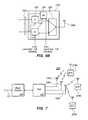
- FIG. 7illustrates a distributed antenna communications system and base station having signal metering capability in accordance with an embodiment of the present invention.
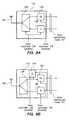
- FIGS. 8A-Billustrate a transceiver for interfacing with a base station having signal metering capability in accordance with embodiments of the present invention.
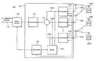
- FIG. 1illustrates a distributed antenna communications system 100 in accordance with an embodiment of the present invention.
- the system 100includes a communications hub 102 , and a plurality of distributed antennas 106 a - n coupled to ports of the hub 102 .
- a base transceiver station 104is communicatively coupled to the hub 102 .
- one or more mobile communications devices 108 a - nare communicatively coupled to the hub 102 via the antennas 106 a - n .
- the base station 104may be located at the site of a cellular service provider and may be coupled to a cellular telecommunication network via a backhaul 110 .
- the hub 102may be located at the premises of a telecommunications subscriber with the antennas 106 a - n being distributed throughout the premises.
- the hub 102may be located within a building (e.g., in a utility room) with the antennas distributed throughout the building so as to provide indoor coverage areas for mobile devices 108 a - n .
- the mobile devices 108 a - nmay be, for example, cell phones. While three mobile devices 108 a - n and three antennas 106 a - n are illustrated, it will be apparent that more or fewer of either may be present.
- up to eight antennas 106 a - nmay be coupled to a single hub 102 . Additionally, one or more of the antennas 106 a - n may be located outdoors.
- the base station 104 and hub 102may be co-located.
- functionality of the base station 104may be integrated with that of the hub 102 into a single piece of equipment located at the subscriber premises.
- the system 100preferably provides for two-way communications.
- telecommunications signalsare received by the base station 104 from the cellular telecommunication network and distributed to the antennas 106 a - n .
- a transceiver 112may receive the downlink signal from the base station 104 .
- the transceiver 112then amplifies the downlink signal to an appropriate level for forwarding to a distribution node 114 .
- the distribution node 114then repeats and distributes the signal to a plurality of transceivers 116 a - n such that each of the transceivers 116 a - n receives a copy of the downlink signal.
- the transceivers 116 a - neach transmit the signal received from the distribution node 114 via a corresponding one of the antennas 106 a - n .
- the mobile devices 108 a - neach pick up the downlink signal from one or more of the antennas 106 a - n.
- signals from the mobile devices 108 a - nare received by the transceivers 116 a - n via the antennas 106 a - n .
- the signalsare then forwarded to the distribution node 114 which combines the signals (e.g., by simple summation) into a combined signal.
- the combined signalis transmitted to the base station 104 by the transceiver 112 .
- the base station 104then forwards the combined signal to the cellular telecommunication network.
- the downlink signal from the base station 104is RF (Radio Frequency).
- this signalis communicated via a cable or via a wireless link between the transceiver 112 and the base station 104 .
- the transceiver 112may down-convert the downlink signal from RF to IF.
- This signalis then distributed to the transceivers 116 a - n in IF.
- the transceivers 116 a - nup-convert the IF signal to RF (Radio Frequency) before transmitting the signal to the mobile devices 108 a - n .
- the transceivers 116 a - nDown-convert RF signals received from the mobile devices 108 a - n to IF. These IF signals are then processed and combined for delivery to the transceiver 112 in IF. The transceiver 112 then up-converts the IF signal to RF for delivery the base station 104 . Accordingly, the transceiver 112 functions as an interface to the telephone network via the base station 104 .
- CDMACode-Division, Multiple Access
- UMTSUniversal Mobile Telecommunications System
- TDMATime-Division, Multiple-Access protocols for cellular communication
- GSMGlobal System for Mobile Communications
- the same signal including the various channelsis transmitted via each of the antennas 106 a - n so that it may be received by any of the mobile devices 108 a - n without regard to which of the antennas 106 a - n is closest to a particular one of the mobile devices.
- the signal from a particular mobile devicemay be picked up by one or more antennas 106 a - n .
- the signal from device 108 ais picked up by antennas 106 a and 106 b , though the signal may be stronger at one of the antennas than the other.
- the signal from device 108 bis picked up only by antenna 106 n .
- the signal from device 108 nis also picked up only by the antenna 106 n . All of the signals picked up by any of the antennas 106 a - n are combined at node 114 and included in the combined signal received at the base station 104 .
- the hub 102may also include a controller 118 and a meter 120 , whose functions are described in more detail herein.
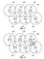
- FIG. 2illustrates cellular coverage areas 202 A-F or “cells” of a cellular telecommunication network 200 in which the distributed antenna system 100 of FIG. 1 may be deployed.
- Each of the cells 202 A-Fis roughly centered about a corresponding one of base stations 204 A-F. While six such cells are shown, it will be apparent that a cellular network could be comprised of a different number of cells.
- a large cellular networkmay comprise tens or even hundreds of cells which provide coverage for a large geographical area. In this case, many of the cells may be completely surrounded by adjacent neighbor cells.
- FIG. 3illustrates the distributed antenna system 100 being deployed in the cellular network 200 of FIG. 2 .
- the distributed antenna system 100forms a coverage area 206 .
- the coverage area 206is shown having an irregular shape because the antennas 106 a - n ( FIG. 1 ) may be positioned in various different locations.
- one or more of the antennas 106 a - nmay be located within a building, the structure of which will tend to attenuate signal strength.
- the coverage area 206 of the distributed antenna system 100may overlap one or more of the cells 202 A-F of the cellular network 200 , it is possible for interference to occur between the distributed antenna system 100 and one or more of the cells of the cellular network 200 .
- the distributed antenna system 100is preferably configured so as to avoid employing any of the communication frequencies that are used by those cells of the network 200 whose coverage areas overlap that of the distributed antenna system 100 unless the signal strength of the cells of the network 200 in the overlapping coverage area is sufficiently low that interference is unlikely.
- normal operation of the distributed antenna system 100is shown.
- the distributed antenna system 100transmits signals via the transceivers 116 a - n using transmission frequencies assigned to the downlink signaling direction.
- the distributed antenna system 100also receives signals via the transceivers 116 a - n in frequencies assigned to the uplink signaling direction.
- the normal modeis used for facilitating communications for the mobile units 108 a - n .
- the base stations 204 A-F of the cellular network 200shown in FIGS. 2 and 3 ) also transmit signals using downlink frequencies.
- the base stations 204 A-Falso receive signals in frequencies assigned to the uplink signaling direction. Therefore, the base stations 204 A-F and the distributed antenna system 100 may interfere with one another by attempting to transmit different information at the same frequency and in the same area. However, the base stations 204 A-F and the distributed antenna system 100 would not “see” each other because they are each configured to only receive signals assigned to the uplink signaling direction.
- FIG. 4illustrates the distributed antenna communications system 100 being configured for deployment in the cellular network 200 in accordance with an embodiment of the present invention.
- the transceivers 116 a - nare configured to receive signals in frequency bands transmitted by the base stations 204 A-F (downlink frequencies). Therefore, in this mode of operation, which may be referred to as “listening” or “mobile” mode, the transceivers 116 a - n are configured to receive signals assigned to the downlink signaling direction. In this mode, however, the distributed antenna system 100 may be unable to facilitate communications with the mobile units 108 a - n because the mobile units 108 a - n only transmit in frequencies assigned to the uplink signaling direction.
- the distributed antenna system 100detects signals from the base stations 204 A-F of the cellular network 200 by listening for their downlink signals. This is used to identify downlink frequencies used by the base stations 204 A-F which might interfere with transmissions by the distributed antenna system 100 . Interference is then avoided by selecting transmission frequencies for use by the distributed antenna system 100 in normal mode that differ from those whose signal strength detected during listening mode is sufficiently strong that interference is likely to occur.
- the controller 118may instruct the transceivers 116 a - n of the distributed antenna system 100 to tune their receive frequencies to correspond to the frequencies assigned to the downlink signaling direction.
- the distributed antenna system 100may be configured to operate in a specific frequency band containing several frequency channels.
- the transceivers 116 a - nmay be tuned to a first one of the channels within the band.
- the transceivers 116 a - nmay be instructed to cease transmitting.
- the meter 120is coupled to lines 122 a - n from each of the transceivers 116 a - n .
- the meter 120monitors the received signals via lines 122 a - n to determine their levels and, thus, field strengths received at antennas 106 a - n .
- the meter 120may first determine the field strength for the first frequency channel.
- the meter 120may simultaneously monitor all of the lines 122 a - n or, alternatively, the meter 120 may cycle through the lines 122 a - n , measuring the field strengths on the lines 122 a - n one-at-a-time.
- the transceivers 116 a - nmay then be tuned to the next frequency channel in the band so that the field strength measurements may be taken for that frequency channel. This process may be continued until the field strength for each frequency channel within the band is measured for each of the transceivers 116 a - n . Rather than measuring the field strength for a frequency channel for all of the transceivers 106 a - n and then measuring the field strength for a next channel, the field strength for all of the channels may be measured for a single transceiver before measuring the field strength for all of the channels for the next transceiver. In other words, the order in which the field strength measurements are taken may vary.
- this informationmay be used to configure the transceivers 116 a - n to transmit using a frequency that differs from any of those identified as having a field strength that sufficiently strong that interference is likely.
- the distributed antenna system 100may be configured to transmit using a specified channel within a frequency band. In this way, interference between the distributed antenna system 100 and any overlapping cells of the cellular network 100 is avoided. The distributed antenna system 100 may then enter normal mode in which the selected transmission frequency is used. Selection of a transmission frequency for the downlink will typically also involve selecting a paired receive frequency for the uplink.
- the distributed antenna system 100may monitor each of the bands while in listening mode. This may be accomplished by tuning the transceivers 116 a - n to one of the bands first, and then to another, until all the bands have been monitored. If the distributed antenna system 100 supports multiple bands, such 900 MHz or 1800 MHz, but is able to operate in only one band at a time, it may be unnecessary to detect frequencies in all of the bands. This is because the distributed antenna system 100 need only avoid interference in the bands in which it is actually operating. In this case, a human operator may configure the distributed antenna system 100 to select its operating band. Alternatively, the distributed antenna system 100 may automatically select the most-recent frequency band that used by the distributed antenna system 100 or that was used by the base station 104 for monitoring in listening mode.
- the distributed antenna system 100may monitor each of the bands while in listening mode. This may be accomplished by tuning the transceivers 116 a - n to one of the bands first, and then to another, until all the bands have been monitored. If the distributed antenna system 100 supports multiple bands
- the transceivers 116 a - nare tunable to the various channels within a frequency band (i.e. the transceivers are channelized).
- the transceivers 116 a - nmay be tuned to simultaneously receive several frequencies within a band (i.e. the transceivers are broadband).
- the meter 120may be provided with a tunable filter in order to obtain field strength measurements for each channel.
- FIG. 5illustrates the field strength meter 120 in accordance with an embodiment of the present invention.
- the meter 120includes a tunable filter 124 which is coupled to each of the lines 122 a - n .
- the tunable filter 124is controlled by the controller 118 to tune to each channel.
- a signal level meter 126is coupled to the tunable filter 124 to obtain the field strength measurements and to report them to the controller 118 .
- the transceivers 116 a - nare reconfigured to receive frequencies assigned to the downlink.
- the transceivers 116 a - ninclude an tunable receive signal path which can be tuned to the downlink frequencies.
- FIG. 6Aillustrates a transceiver 116 n having a tunable receive signal path in accordance with an embodiment of the present invention.
- the transceiver 116 nincludes a tunable duplexer 128 which is coupled to the antenna 106 n . Signals received by the antenna 106 n are allowed to pass through the duplexer 128 and a receiver 130 before being passed to other elements of the hub 102 via line 122 n .
- the receiver 130may perform filtering and frequency down-converting of the received signal. As shown in FIG. 6A , the receive signal path, including the duplexer 128 and receiver 130 , are tunable under control of the controller 118 depending upon whether the system is in listening mode or normal mode. In addition, a transmitter 132 may be disabled by the controller 118 during listening mode. In normal mode, the transmitter 132 may perform such functions as signal filtering and frequency up-conversion.
- the transceivers 116 a - nmay include an alternative signal path for listening mode.
- FIG. 6Billustrates a transceiver 116 n having an alternative receive signal path in accordance with an embodiment of the present invention.
- the transceiver 116 nincludes a duplexer 128 , a receiver 130 and a transmitter 132 .
- the receiver 130receives signals from the antenna 106 n via the duplexer 128 and the transmitter 132 sends signals to the antenna 106 n via the duplexer 128 .
- the receiver 130is configured to receive signals within the frequency range assigned to the uplink.
- the transceiver 116 nincludes an alternative signal path through a second receiver 134 .
- the second receiver 134is configured to receive signals within the frequency range assigned to the downlink.
- the second receiver 134may be coupled to the transmit side of the duplexer 128 for receiving signals from the duplexer 128 during listening mode. This is because the duplexer 128 is configured such that its transmit side will pass the range of frequencies assigned to the downlink. During listening mode, the received signals are also within the downlink frequencies.
- the output of the receiver 134is coupled to the receive signal path at the output of the receiver 130 .
- the controller 118disables the receive signal path by disabling the receiver 130 and enables the alternative receive signal path by enabling the receiver 134 .
- the receive signal pathis enabled by enabling the receiver 130 , while the alternative receive signal path is disabled by disabling the receiver 134 .
- the second receiver 134may be coupled to the antenna 106 n .
- the alternative receive signal pathbypasses the duplexer 128 .
- the second receiver 134may include a filter between the antenna 106 a and its receive circuitry.
- each remote antenna 106 a - nis preferably measured separately.
- the distributed antenna system 100may then report the results to the base station 104 , to a server coupled to the distributed antenna system 100 or to some other location via the cellular telecommunication network to which the base station 104 is connected.
- a determination of which transmission frequency (including downlink and uplink pair) is be used by the distributed antenna system 100 while in normal modemay be determined automatically based on the reported results. This automatic determination may be performed by the base station 104 or by a server coupled to the distributed antenna system 100 .
- a human operatormay review the results and determine which transmission frequency is to be used by the distributed antenna system 100 when in normal mode.
- the transmission frequencymay be determined by the controller 118 . In this case, the distributed antenna system 100 may not report the results, but may simply adopt the self-determined transmission frequency.
- Results determined during listening modemay be reported in the form of a table.
- the controller 118may generate and report the table.
- Table 1shows an exemplary table which may be reported during listening mode.
- Table 1shows measured field strengths related to each antenna 106 a - n .
- Table 1includes a row for each antenna 108 a - n . Included in the row for a particular antenna is the measured field strength measurements for each frequency (or frequencies) for which the measurements are taken.
- the frequencies at which the field strength measurements are taken for each antenna unitare given as F 1 , F 2 , F 3 , . . . F N while the corresponding field strength measurements are given as A 1 , A 2 , A 3 , . . . A N .
- this informationis also recorded in the table, e.g. as no entry or ⁇ . It will be apparent that Table 1 is exemplary and that the results may be arranged differently.
- the transmission frequency selected for use by the distributed antenna system 100 during normal modeis preferably one that is not being used by any of the overlapping cells of the cellular network 200 ( FIGS. 2 and 3 ).
- the frequency selected for use by the distributed antenna system 100may be one that is being used by an overlapping cell. For example, during listening mode, it may be discovered that a particular frequency is being used by a nearby cell, but that the signal is only received weakly by a limited number of the antennas 106 a - n . In this case, it can be expected that if the antennas 106 a - n are located indoors, any interference will be minimal.
- the distributed antenna system 100may be configured so that a particular one or more of the antennas 106 a - n transmits at a lower power. These particular antennas 106 a - n are selected to be those whose coverage area overlaps the coverage area of a cell of the network 200 . This may be accomplished by the controller 118 causing the transceivers 116 a - n corresponding to the particular antennas to transmit at the lower power.
- the distributed antenna system 100switches from normal mode to listening mode in response to an information message.
- the base station 104may send a message to the controller 118 of the distributed antenna system 100 instructing the distributed antenna system 100 to switch from normal mode to listening mode.
- a servermay be connected to the controller 118 through an Ethernet connection; in this case, an operator or software at the server may send the message.
- Such a messagemay also identify a frequency band in which the distributed antenna system 100 is to listen and possibly the channels within the band.
- the controller 118may instruct the transceivers 116 a - n to tune to frequencies in the specified frequency band.
- the distributed antenna system 100may receive a second message instructing the distributed antenna system 100 to switch back to normal mode.
- This second messagemay also include information which is used to configure the distributed antenna system 100 for normal mode.
- This informationmay include the identification of a frequency pair to be used by the distributed antenna system 100 for the downlink and uplink signaling with the mobile devices 108 a - n ( FIG. 1 ).
- the distributed antenna system 100may the enter listening mode upon being powered on. Then, once the appropriate information is gathered in listening mode, the distributed antenna system 100 may switch back to normal mode.
- the distributed antenna system 100may default to the listening mode unless it detects a communication signal from its connected base station 104 . More particularly, when the distributed antenna system 100 does not detect any communications signal from the base station 104 , it may default to the listening mode. Then, in response to the distributed antenna system 100 detecting a communications signal from the base station 104 , the distributed antenna system 100 switches to the normal mode. During the listening mode, taking of the field strength measurements may performed under control of the base station 104 . In this embodiment, the field strength meter 120 may be included in the base station 104 rather than in the hub 102 .
- the base station 104may take its field strength measurements from the combined signal received from all of the antennas 106 a - n . The base station 104 may then inform the distributed antenna system 100 of the frequency pair to be used by the distributed antenna system 100 for normal mode before the base station 104 commences transmitting in normal mode.
- the base station 104may include signal metering capability. In this case, the base station 104 may perform the field strength measurements.
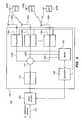
- FIG. 7illustrates a distributed antenna communications system 300 and a base station 104 having signal metering capabilities.
- the base station 104is coupled to the hub 102 , which is, in turn, coupled to multiple antennas 106 a - n .
- the system 300operates in a normal mode, in which the antennas 106 a - n perform bi-directional communications with mobile units and, in a listening mode, in which the system 300 determines whether there is any overlap with cells of the network 200 ( FIGS. 2 and 3 ).
- the base station 104is configured to listen to the downlink frequencies of the neighboring base stations 108 a - n . Because the signals from each of the distributed antennas 106 a - n are combined by the hub 102 , the base station 104 may measure the field strength of the combined signal. The base station 104 may then perform signal field strength measurements and instruct the hub 102 to configure its transceivers 116 a - n to operate in an appropriate downlink frequency. Alternatively, the base station 104 may send the results to a server or to a human operator via the connected cellular telecommunication network, as described above in connection with FIG. 4 .
- the embodiment of FIG. 7preferably enters and exits listening mode without requiring signaling between the hub 102 and base station 104 .
- the hub 102may default to the listening mode unless it detects a communication signal from its connected base station 104 . Then, in response to the hub 102 detecting a communications signal from the base station 104 , it may switch to the normal mode.
- the hub 102is reconfigured to transmit frequencies assigned to the downlink to the base station 104 ( FIGS. 1 and 4 ) so that the base station 104 can perform the field strength measurements.
- the transceiver 112 of the hub 102may include a tunable transmit signal path which can be tuned to the downlink frequencies during listening mode.
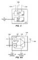
- FIG. 8Aillustrates a transceiver 112 having a tunable transmit signal path in accordance with an embodiment of the present invention. As shown in FIG. 8A , the transceiver 112 includes a tunable transmitter 136 and a tunable duplexer 138 .
- the duplexer 138is coupled to an antenna 140 which is used to communicate with the base station 140 .
- Signals received from the distributed antennas 116 a - nare passed through other elements of the hub 102 (e.g. the distribution node 114 ) and then to the transmitter 136 .
- the transmitter 136may perform such functions as signal filtering and frequency up-conversion.
- the signal from the transmitter 136is then forwarded to the base station 104 via the duplexer 138 and antenna 140 .
- the transmit signal path, including the transmitter 136 and duplexer 138are tunable under control of the controller 118 depending upon whether the system is in listening mode or normal mode.
- a receiver 142which is used for the downlink during normal mode, may be disabled by the controller 118 during listening mode. In normal mode, the receiver 142 may perform such functions as signal filtering and frequency down-conversion.
- the transceiver 112may include an alternative signal path for listening mode.
- FIG. 8Billustrates a transceiver 112 having an alternative transmit signal path in accordance with an embodiment of the present invention.
- the transceiver 112includes a duplexer 138 , a transmitter 136 and a receiver 142 .
- the transmitter 136sends uplink signals to the base station 104 via the duplexer 138 and antenna 140 while the receiver 142 receives downlink signals from the base station 104 via the antenna 140 and the duplexer 138 .
- the transceiver 136is configured to transmit signals within the frequency range assigned to the uplink.
- the transceiver 112includes an alternative signal path through a second transmitter 144 .
- the second transmitter 144is configured to transmit signals within the frequency range assigned to the downlink.
- the second transmitter 144may be coupled to the receive side of the duplexer 138 for transmitting signals via the duplexer 138 during listening mode. This is because the duplexer 138 is configured such that its receive side will pass the range of frequencies assigned to the downlink. During listening mode, the signals to be transmitted to the base station 104 are also within the downlink frequencies.
- the input of the transmitter 144is coupled to the transmit signal path at the input of the transmitter 136 .
- the controller 118disables the transmit signal path by disabling the transmitter 136 and enables the alternative transmit signal path by enabling the transmitter 144 .
- the transmit signal pathis enabled by enabling the transmitter 136 , while the alternative transmit signal path is disabled by disabling the transmitter 144 .
- the second transmitter 144may be coupled to the antenna 140 .
- the alternative transmit signal pathbypasses the duplexer 138 .
- the second transmitter 144may include a filter between the antenna 140 and its transmit circuitry.
- the transceiver 112may be coupled to the base station via two separate signal paths (e.g., separate cables) each carrying signals in one direction only.
- the tunable transceiver 136 of FIG. 8Amay be coupled to either one of the separate signal paths between the hub 102 and the base station 104 .
- the alternative transmit signal path of FIG. 8Bmay be coupled to either one of the separate signal paths between the hub 102 and the base station 104 .
Landscapes
- Engineering & Computer Science (AREA)
- Computer Networks & Wireless Communication (AREA)
- Signal Processing (AREA)
- Mobile Radio Communication Systems (AREA)
Abstract
Description
| Field Strength(s) | |||
| Antenna Unit | F1, F2, F3, . . . | ||
| 108a | A1, A2, A3, . . . AN | ||
| 108b | A1, A2, A3, . . . AN | ||
| . | . | ||
| . | . | ||
| . | . | ||
| 108n | A1, A2, A3, . . . AN | ||
Claims (28)
Priority Applications (5)
| Application Number | Priority Date | Filing Date | Title |
|---|---|---|---|
| US11/897,728US9112547B2 (en) | 2007-08-31 | 2007-08-31 | System for and method of configuring distributed antenna communications system |
| PCT/US2007/023518WO2009029077A1 (en) | 2007-08-31 | 2007-11-08 | System for and method of configuring distributed antenna communications system |
| CA2697787ACA2697787C (en) | 2007-08-31 | 2007-11-08 | System for and method of configuring distributed antenna communications system |
| CN2007801012930ACN101842995B (en) | 2007-08-31 | 2007-11-08 | System for and method of configuring distributed antenna communications system |
| EP07861832.9AEP2186206B1 (en) | 2007-08-31 | 2007-11-08 | System for and method of configuring distributed antenna communications system |
Applications Claiming Priority (1)
| Application Number | Priority Date | Filing Date | Title |
|---|---|---|---|
| US11/897,728US9112547B2 (en) | 2007-08-31 | 2007-08-31 | System for and method of configuring distributed antenna communications system |
Publications (2)
| Publication Number | Publication Date |
|---|---|
| US20090061940A1 US20090061940A1 (en) | 2009-03-05 |
| US9112547B2true US9112547B2 (en) | 2015-08-18 |
Family
ID=40387586
Family Applications (1)
| Application Number | Title | Priority Date | Filing Date |
|---|---|---|---|
| US11/897,728Active2034-06-09US9112547B2 (en) | 2007-08-31 | 2007-08-31 | System for and method of configuring distributed antenna communications system |
Country Status (5)
| Country | Link |
|---|---|
| US (1) | US9112547B2 (en) |
| EP (1) | EP2186206B1 (en) |
| CN (1) | CN101842995B (en) |
| CA (1) | CA2697787C (en) |
| WO (1) | WO2009029077A1 (en) |
Cited By (18)
| Publication number | Priority date | Publication date | Assignee | Title |
|---|---|---|---|---|
| US9184843B2 (en) | 2011-04-29 | 2015-11-10 | Corning Optical Communications LLC | Determining propagation delay of communications in distributed antenna systems, and related components, systems, and methods |
| US9219879B2 (en) | 2009-11-13 | 2015-12-22 | Corning Optical Communications LLC | Radio-over-fiber (ROF) system for protocol-independent wired and/or wireless communication |
| US9240835B2 (en) | 2011-04-29 | 2016-01-19 | Corning Optical Communications LLC | Systems, methods, and devices for increasing radio frequency (RF) power in distributed antenna systems |
| US9319138B2 (en) | 2010-02-15 | 2016-04-19 | Corning Optical Communications LLC | Dynamic cell bonding (DCB) for radio-over-fiber (RoF)-based networks and communication systems and related methods |
| US9357551B2 (en) | 2014-05-30 | 2016-05-31 | Corning Optical Communications Wireless Ltd | Systems and methods for simultaneous sampling of serial digital data streams from multiple analog-to-digital converters (ADCS), including in distributed antenna systems |
| US9455784B2 (en) | 2012-10-31 | 2016-09-27 | Corning Optical Communications Wireless Ltd | Deployable wireless infrastructures and methods of deploying wireless infrastructures |
| US9479244B1 (en)* | 2015-11-25 | 2016-10-25 | At&T Intellectual Propery I, L.P. | Radio frequency repeater system for signal transmission through radio frequency shielding material in connected home applications |
| US20170026062A1 (en)* | 2012-03-23 | 2017-01-26 | Corning Optical Communications Wireless Ltd | Radio-frequency integrated circuit (rfic) chip(s) for providing distributed antenna system functionalities, and related components, systems, and methods |
| US9565596B2 (en) | 2011-08-29 | 2017-02-07 | Commscope Technologies Llc | Configuring a distributed antenna system |
| US9673904B2 (en) | 2009-02-03 | 2017-06-06 | Corning Optical Communications LLC | Optical fiber-based distributed antenna systems, components, and related methods for calibration thereof |
| US9681313B2 (en) | 2015-04-15 | 2017-06-13 | Corning Optical Communications Wireless Ltd | Optimizing remote antenna unit performance using an alternative data channel |
| US20180027431A1 (en)* | 2015-04-17 | 2018-01-25 | Solid, Inc. | Node unit of distributed antenna system |
| US9948349B2 (en) | 2015-07-17 | 2018-04-17 | Corning Optical Communications Wireless Ltd | IOT automation and data collection system |
| US10128951B2 (en) | 2009-02-03 | 2018-11-13 | Corning Optical Communications LLC | Optical fiber-based distributed antenna systems, components, and related methods for monitoring and configuring thereof |
| US10136200B2 (en) | 2012-04-25 | 2018-11-20 | Corning Optical Communications LLC | Distributed antenna system architectures |
| US10142009B2 (en) | 2010-04-27 | 2018-11-27 | Andrew Wireless Systems Gmbh | Interface module for a unit of an antenna distribution system, and antenna distribution system |
| US10149304B2 (en) | 2014-02-21 | 2018-12-04 | Commscope Technologies Llc | Optimizing network resources in a telecommunications system |
| US11671914B2 (en) | 2010-10-13 | 2023-06-06 | Corning Optical Communications LLC | Power management for remote antenna units in distributed antenna systems |
Families Citing this family (204)
| Publication number | Priority date | Publication date | Assignee | Title |
|---|---|---|---|---|
| WO2009034614A1 (en)* | 2007-09-11 | 2009-03-19 | Fujitsu Limited | Wireless base station and method for controlling the same |
| US9002300B2 (en)* | 2010-09-30 | 2015-04-07 | Broadcom Corporation | Method and system for time division duplexing (TDD) in a 60 GHZ distributed communication system |
| US9008593B2 (en)* | 2010-09-30 | 2015-04-14 | Broadcom Corporation | Method and system for 60 GHz distributed communication |
| US8942646B2 (en)* | 2010-09-30 | 2015-01-27 | Broadcom Corporation | Method and system for a 60 GHz communication device comprising multi-location antennas for pseudo-beamforming |
| US8942645B2 (en)* | 2010-09-30 | 2015-01-27 | Broadcom Corporation | Method and system for communication via subbands in a 60 GHZ distributed communication system |
| US8977219B2 (en)* | 2010-09-30 | 2015-03-10 | Broadcom Corporation | Method and system for mitigating leakage of a 60 GHz transmitted signal back into an RF input of a 60 GHz device |
| US8942647B2 (en)* | 2010-09-30 | 2015-01-27 | Broadcom Corporation | Method and system for antenna switching for 60 GHz distributed communication |
| WO2009104144A1 (en)* | 2008-02-19 | 2009-08-27 | Nxp B.V. | Software defined radio |
| US8346278B2 (en)* | 2009-01-13 | 2013-01-01 | Adc Telecommunications, Inc. | Systems and methods for mobile phone location with digital distributed antenna systems |
| USRE47466E1 (en) | 2009-01-13 | 2019-06-25 | Commscope Technologies Llc | Systems and methods for IP communication over a distributed antenna system transport |
| US8213401B2 (en)* | 2009-01-13 | 2012-07-03 | Adc Telecommunications, Inc. | Systems and methods for IP communication over a distributed antenna system transport |
| AU2011274307B2 (en) | 2010-06-29 | 2016-07-14 | Commonwealth Scientific And Industrial Research Organisation | Dynamic network configuration |
| US8472579B2 (en) | 2010-07-28 | 2013-06-25 | Adc Telecommunications, Inc. | Distributed digital reference clock |
| US9042838B2 (en)* | 2010-08-25 | 2015-05-26 | Intel Corporation | Transmit leakage cancellation in a wide bandwidth distributed antenna system |
| US8532242B2 (en) | 2010-10-27 | 2013-09-10 | Adc Telecommunications, Inc. | Distributed antenna system with combination of both all digital transport and hybrid digital/analog transport |
| JP5432882B2 (en)* | 2010-11-25 | 2014-03-05 | 株式会社日立製作所 | Distributed antenna system, distributed antenna switching method, base station apparatus, and antenna switch apparatus |
| BR112013030768B1 (en) | 2011-06-01 | 2022-12-06 | Commscope Technologies Llc | DISTRIBUTED ANTENNA SYSTEM |
| KR102067099B1 (en)* | 2011-06-09 | 2020-02-11 | 콤스코프 테크놀로지스, 엘엘씨 | Distributed antenna system interface for processing digital signals in a standardized format |
| CN102281548A (en)* | 2011-08-01 | 2011-12-14 | 深圳市云海通讯股份有限公司 | Frequency domain decomposition-long term evolution (FDD-LTE) indoor coverage system |
| US9270346B2 (en) | 2011-12-02 | 2016-02-23 | Apple Inc. | Methods for operating wireless electronic devices in coordinated multipoint transmission networks |
| US8254848B1 (en)* | 2011-12-09 | 2012-08-28 | At&T Intellectual Property I, Lp | Monitoring system for distributed antenna systems |
| EP3422589B1 (en)* | 2012-02-02 | 2024-07-24 | CommScope Technologies LLC | Optimized telecommunications distribution system |
| US9306682B2 (en)* | 2012-07-20 | 2016-04-05 | Commscope Technologies Llc | Systems and methods for a self-optimizing distributed antenna system |
| KR101541262B1 (en) | 2012-08-09 | 2015-07-31 | 악셀 와이어리스 리미티드 | A digital capactiy centric distributed antenna system |
| EP2904831B1 (en) | 2012-10-05 | 2017-10-04 | Andrew Wireless Systems GmbH | Capacity optimization sub-system for distributed antenna system |
| US9113347B2 (en) | 2012-12-05 | 2015-08-18 | At&T Intellectual Property I, Lp | Backhaul link for distributed antenna system |
| US10009065B2 (en) | 2012-12-05 | 2018-06-26 | At&T Intellectual Property I, L.P. | Backhaul link for distributed antenna system |
| WO2014110060A1 (en) | 2013-01-08 | 2014-07-17 | Zone Access Technologies, Inc. | System and method for calibration of a distributed amplifier system |
| CA2914104C (en) | 2013-02-22 | 2022-12-13 | Adc Telecommunications, Inc. | Master reference for base station network interface sourced from distributed antenna system |
| US9999038B2 (en) | 2013-05-31 | 2018-06-12 | At&T Intellectual Property I, L.P. | Remote distributed antenna system |
| US9525524B2 (en) | 2013-05-31 | 2016-12-20 | At&T Intellectual Property I, L.P. | Remote distributed antenna system |
| US9247543B2 (en) | 2013-07-23 | 2016-01-26 | Corning Optical Communications Wireless Ltd | Monitoring non-supported wireless spectrum within coverage areas of distributed antenna systems (DASs) |
| US8897697B1 (en) | 2013-11-06 | 2014-11-25 | At&T Intellectual Property I, Lp | Millimeter-wave surface-wave communications |
| US9209902B2 (en) | 2013-12-10 | 2015-12-08 | At&T Intellectual Property I, L.P. | Quasi-optical coupler |
| TW201524141A (en)* | 2013-12-13 | 2015-06-16 | Amoesolu Corp | Distributed antenna system |
| US9178635B2 (en) | 2014-01-03 | 2015-11-03 | Corning Optical Communications Wireless Ltd | Separation of communication signal sub-bands in distributed antenna systems (DASs) to reduce interference |
| WO2015126730A1 (en)* | 2014-02-18 | 2015-08-27 | Commscope Technologies Llc | Distributed antenna system measurement receiver |
| EP4024719A1 (en) | 2014-04-15 | 2022-07-06 | CommScope Technologies LLC | Wideband remote unit for distributed antenna system |
| US9692101B2 (en) | 2014-08-26 | 2017-06-27 | At&T Intellectual Property I, L.P. | Guided wave couplers for coupling electromagnetic waves between a waveguide surface and a surface of a wire |
| US9768833B2 (en) | 2014-09-15 | 2017-09-19 | At&T Intellectual Property I, L.P. | Method and apparatus for sensing a condition in a transmission medium of electromagnetic waves |
| US10063280B2 (en) | 2014-09-17 | 2018-08-28 | At&T Intellectual Property I, L.P. | Monitoring and mitigating conditions in a communication network |
| US10396917B2 (en) | 2014-09-23 | 2019-08-27 | Axell Wireless Ltd. | Automatic mapping and handling PIM and other uplink interferences in digital distributed antenna systems |
| US9628854B2 (en) | 2014-09-29 | 2017-04-18 | At&T Intellectual Property I, L.P. | Method and apparatus for distributing content in a communication network |
| US9615269B2 (en) | 2014-10-02 | 2017-04-04 | At&T Intellectual Property I, L.P. | Method and apparatus that provides fault tolerance in a communication network |
| US9685992B2 (en) | 2014-10-03 | 2017-06-20 | At&T Intellectual Property I, L.P. | Circuit panel network and methods thereof |
| US9503189B2 (en) | 2014-10-10 | 2016-11-22 | At&T Intellectual Property I, L.P. | Method and apparatus for arranging communication sessions in a communication system |
| US9973299B2 (en) | 2014-10-14 | 2018-05-15 | At&T Intellectual Property I, L.P. | Method and apparatus for adjusting a mode of communication in a communication network |
| US9762289B2 (en) | 2014-10-14 | 2017-09-12 | At&T Intellectual Property I, L.P. | Method and apparatus for transmitting or receiving signals in a transportation system |
| US9577306B2 (en) | 2014-10-21 | 2017-02-21 | At&T Intellectual Property I, L.P. | Guided-wave transmission device and methods for use therewith |
| US9769020B2 (en) | 2014-10-21 | 2017-09-19 | At&T Intellectual Property I, L.P. | Method and apparatus for responding to events affecting communications in a communication network |
| US9653770B2 (en) | 2014-10-21 | 2017-05-16 | At&T Intellectual Property I, L.P. | Guided wave coupler, coupling module and methods for use therewith |
| US9564947B2 (en) | 2014-10-21 | 2017-02-07 | At&T Intellectual Property I, L.P. | Guided-wave transmission device with diversity and methods for use therewith |
| US9627768B2 (en) | 2014-10-21 | 2017-04-18 | At&T Intellectual Property I, L.P. | Guided-wave transmission device with non-fundamental mode propagation and methods for use therewith |
| US9780834B2 (en) | 2014-10-21 | 2017-10-03 | At&T Intellectual Property I, L.P. | Method and apparatus for transmitting electromagnetic waves |
| US9312919B1 (en) | 2014-10-21 | 2016-04-12 | At&T Intellectual Property I, Lp | Transmission device with impairment compensation and methods for use therewith |
| US9520945B2 (en) | 2014-10-21 | 2016-12-13 | At&T Intellectual Property I, L.P. | Apparatus for providing communication services and methods thereof |
| US9800327B2 (en) | 2014-11-20 | 2017-10-24 | At&T Intellectual Property I, L.P. | Apparatus for controlling operations of a communication device and methods thereof |
| US9680670B2 (en) | 2014-11-20 | 2017-06-13 | At&T Intellectual Property I, L.P. | Transmission device with channel equalization and control and methods for use therewith |
| US9461706B1 (en) | 2015-07-31 | 2016-10-04 | At&T Intellectual Property I, Lp | Method and apparatus for exchanging communication signals |
| US10009067B2 (en) | 2014-12-04 | 2018-06-26 | At&T Intellectual Property I, L.P. | Method and apparatus for configuring a communication interface |
| US9654173B2 (en) | 2014-11-20 | 2017-05-16 | At&T Intellectual Property I, L.P. | Apparatus for powering a communication device and methods thereof |
| US9544006B2 (en) | 2014-11-20 | 2017-01-10 | At&T Intellectual Property I, L.P. | Transmission device with mode division multiplexing and methods for use therewith |
| US10340573B2 (en) | 2016-10-26 | 2019-07-02 | At&T Intellectual Property I, L.P. | Launcher with cylindrical coupling device and methods for use therewith |
| US9742462B2 (en) | 2014-12-04 | 2017-08-22 | At&T Intellectual Property I, L.P. | Transmission medium and communication interfaces and methods for use therewith |
| US10243784B2 (en) | 2014-11-20 | 2019-03-26 | At&T Intellectual Property I, L.P. | System for generating topology information and methods thereof |
| US9954287B2 (en) | 2014-11-20 | 2018-04-24 | At&T Intellectual Property I, L.P. | Apparatus for converting wireless signals and electromagnetic waves and methods thereof |
| US9997819B2 (en) | 2015-06-09 | 2018-06-12 | At&T Intellectual Property I, L.P. | Transmission medium and method for facilitating propagation of electromagnetic waves via a core |
| AU2015371287A1 (en) | 2014-12-23 | 2017-06-08 | Axell Wireless Ltd. | Harmonizing noise aggregation and noise management in distributed antenna system |
| US10144036B2 (en) | 2015-01-30 | 2018-12-04 | At&T Intellectual Property I, L.P. | Method and apparatus for mitigating interference affecting a propagation of electromagnetic waves guided by a transmission medium |
| US20160249365A1 (en) | 2015-02-19 | 2016-08-25 | Corning Optical Communications Wireless Ltd. | Offsetting unwanted downlink interference signals in an uplink path in a distributed antenna system (das) |
| US9876570B2 (en) | 2015-02-20 | 2018-01-23 | At&T Intellectual Property I, Lp | Guided-wave transmission device with non-fundamental mode propagation and methods for use therewith |
| EP3272027B1 (en)* | 2015-03-16 | 2024-05-01 | Commscope Technologies LLC | Das management by radio access network node |
| US9749013B2 (en) | 2015-03-17 | 2017-08-29 | At&T Intellectual Property I, L.P. | Method and apparatus for reducing attenuation of electromagnetic waves guided by a transmission medium |
| US10224981B2 (en) | 2015-04-24 | 2019-03-05 | At&T Intellectual Property I, Lp | Passive electrical coupling device and methods for use therewith |
| US9705561B2 (en) | 2015-04-24 | 2017-07-11 | At&T Intellectual Property I, L.P. | Directional coupling device and methods for use therewith |
| US9793954B2 (en) | 2015-04-28 | 2017-10-17 | At&T Intellectual Property I, L.P. | Magnetic coupling device and methods for use therewith |
| US9948354B2 (en) | 2015-04-28 | 2018-04-17 | At&T Intellectual Property I, L.P. | Magnetic coupling device with reflective plate and methods for use therewith |
| US9766324B2 (en)* | 2015-05-06 | 2017-09-19 | Microsoft Technology Licensing, Llc | Multiple antenna communication system configured to detect objects |
| US9490869B1 (en) | 2015-05-14 | 2016-11-08 | At&T Intellectual Property I, L.P. | Transmission medium having multiple cores and methods for use therewith |
| US9871282B2 (en) | 2015-05-14 | 2018-01-16 | At&T Intellectual Property I, L.P. | At least one transmission medium having a dielectric surface that is covered at least in part by a second dielectric |
| US9748626B2 (en) | 2015-05-14 | 2017-08-29 | At&T Intellectual Property I, L.P. | Plurality of cables having different cross-sectional shapes which are bundled together to form a transmission medium |
| US10650940B2 (en) | 2015-05-15 | 2020-05-12 | At&T Intellectual Property I, L.P. | Transmission medium having a conductive material and methods for use therewith |
| US10679767B2 (en) | 2015-05-15 | 2020-06-09 | At&T Intellectual Property I, L.P. | Transmission medium having a conductive material and methods for use therewith |
| US9917341B2 (en) | 2015-05-27 | 2018-03-13 | At&T Intellectual Property I, L.P. | Apparatus and method for launching electromagnetic waves and for modifying radial dimensions of the propagating electromagnetic waves |
| US9912381B2 (en) | 2015-06-03 | 2018-03-06 | At&T Intellectual Property I, Lp | Network termination and methods for use therewith |
| US10812174B2 (en) | 2015-06-03 | 2020-10-20 | At&T Intellectual Property I, L.P. | Client node device and methods for use therewith |
| US10348391B2 (en) | 2015-06-03 | 2019-07-09 | At&T Intellectual Property I, L.P. | Client node device with frequency conversion and methods for use therewith |
| US10103801B2 (en) | 2015-06-03 | 2018-10-16 | At&T Intellectual Property I, L.P. | Host node device and methods for use therewith |
| US9866309B2 (en) | 2015-06-03 | 2018-01-09 | At&T Intellectual Property I, Lp | Host node device and methods for use therewith |
| US10154493B2 (en) | 2015-06-03 | 2018-12-11 | At&T Intellectual Property I, L.P. | Network termination and methods for use therewith |
| US9913139B2 (en) | 2015-06-09 | 2018-03-06 | At&T Intellectual Property I, L.P. | Signal fingerprinting for authentication of communicating devices |
| US9608692B2 (en) | 2015-06-11 | 2017-03-28 | At&T Intellectual Property I, L.P. | Repeater and methods for use therewith |
| US20160366657A1 (en)* | 2015-06-11 | 2016-12-15 | Collision Communications, Inc. | Methods, Systems, And Computer Program Products For Over The Air Synchronization For Cellular Networks |
| US10142086B2 (en) | 2015-06-11 | 2018-11-27 | At&T Intellectual Property I, L.P. | Repeater and methods for use therewith |
| US9820146B2 (en) | 2015-06-12 | 2017-11-14 | At&T Intellectual Property I, L.P. | Method and apparatus for authentication and identity management of communicating devices |
| US9667317B2 (en) | 2015-06-15 | 2017-05-30 | At&T Intellectual Property I, L.P. | Method and apparatus for providing security using network traffic adjustments |
| US9640850B2 (en) | 2015-06-25 | 2017-05-02 | At&T Intellectual Property I, L.P. | Methods and apparatus for inducing a non-fundamental wave mode on a transmission medium |
| US9509415B1 (en) | 2015-06-25 | 2016-11-29 | At&T Intellectual Property I, L.P. | Methods and apparatus for inducing a fundamental wave mode on a transmission medium |
| US9865911B2 (en) | 2015-06-25 | 2018-01-09 | At&T Intellectual Property I, L.P. | Waveguide system for slot radiating first electromagnetic waves that are combined into a non-fundamental wave mode second electromagnetic wave on a transmission medium |
| US10341142B2 (en) | 2015-07-14 | 2019-07-02 | At&T Intellectual Property I, L.P. | Apparatus and methods for generating non-interfering electromagnetic waves on an uninsulated conductor |
| US9853342B2 (en) | 2015-07-14 | 2017-12-26 | At&T Intellectual Property I, L.P. | Dielectric transmission medium connector and methods for use therewith |
| US10170840B2 (en) | 2015-07-14 | 2019-01-01 | At&T Intellectual Property I, L.P. | Apparatus and methods for sending or receiving electromagnetic signals |
| US9847566B2 (en) | 2015-07-14 | 2017-12-19 | At&T Intellectual Property I, L.P. | Method and apparatus for adjusting a field of a signal to mitigate interference |
| US9836957B2 (en) | 2015-07-14 | 2017-12-05 | At&T Intellectual Property I, L.P. | Method and apparatus for communicating with premises equipment |
| US10148016B2 (en) | 2015-07-14 | 2018-12-04 | At&T Intellectual Property I, L.P. | Apparatus and methods for communicating utilizing an antenna array |
| US9722318B2 (en) | 2015-07-14 | 2017-08-01 | At&T Intellectual Property I, L.P. | Method and apparatus for coupling an antenna to a device |
| US10044409B2 (en) | 2015-07-14 | 2018-08-07 | At&T Intellectual Property I, L.P. | Transmission medium and methods for use therewith |
| US10205655B2 (en) | 2015-07-14 | 2019-02-12 | At&T Intellectual Property I, L.P. | Apparatus and methods for communicating utilizing an antenna array and multiple communication paths |
| US10033108B2 (en) | 2015-07-14 | 2018-07-24 | At&T Intellectual Property I, L.P. | Apparatus and methods for generating an electromagnetic wave having a wave mode that mitigates interference |
| US10320586B2 (en) | 2015-07-14 | 2019-06-11 | At&T Intellectual Property I, L.P. | Apparatus and methods for generating non-interfering electromagnetic waves on an insulated transmission medium |
| US9628116B2 (en) | 2015-07-14 | 2017-04-18 | At&T Intellectual Property I, L.P. | Apparatus and methods for transmitting wireless signals |
| US9882257B2 (en) | 2015-07-14 | 2018-01-30 | At&T Intellectual Property I, L.P. | Method and apparatus for launching a wave mode that mitigates interference |
| US10033107B2 (en) | 2015-07-14 | 2018-07-24 | At&T Intellectual Property I, L.P. | Method and apparatus for coupling an antenna to a device |
| US10090606B2 (en) | 2015-07-15 | 2018-10-02 | At&T Intellectual Property I, L.P. | Antenna system with dielectric array and methods for use therewith |
| US9608740B2 (en) | 2015-07-15 | 2017-03-28 | At&T Intellectual Property I, L.P. | Method and apparatus for launching a wave mode that mitigates interference |
| US9793951B2 (en) | 2015-07-15 | 2017-10-17 | At&T Intellectual Property I, L.P. | Method and apparatus for launching a wave mode that mitigates interference |
| US9912027B2 (en) | 2015-07-23 | 2018-03-06 | At&T Intellectual Property I, L.P. | Method and apparatus for exchanging communication signals |
| US9749053B2 (en) | 2015-07-23 | 2017-08-29 | At&T Intellectual Property I, L.P. | Node device, repeater and methods for use therewith |
| US10784670B2 (en) | 2015-07-23 | 2020-09-22 | At&T Intellectual Property I, L.P. | Antenna support for aligning an antenna |
| US9871283B2 (en) | 2015-07-23 | 2018-01-16 | At&T Intellectual Property I, Lp | Transmission medium having a dielectric core comprised of plural members connected by a ball and socket configuration |
| US9948333B2 (en) | 2015-07-23 | 2018-04-17 | At&T Intellectual Property I, L.P. | Method and apparatus for wireless communications to mitigate interference |
| US10020587B2 (en) | 2015-07-31 | 2018-07-10 | At&T Intellectual Property I, L.P. | Radial antenna and methods for use therewith |
| US9735833B2 (en) | 2015-07-31 | 2017-08-15 | At&T Intellectual Property I, L.P. | Method and apparatus for communications management in a neighborhood network |
| US9967173B2 (en) | 2015-07-31 | 2018-05-08 | At&T Intellectual Property I, L.P. | Method and apparatus for authentication and identity management of communicating devices |
| US9904535B2 (en) | 2015-09-14 | 2018-02-27 | At&T Intellectual Property I, L.P. | Method and apparatus for distributing software |
| US10009063B2 (en) | 2015-09-16 | 2018-06-26 | At&T Intellectual Property I, L.P. | Method and apparatus for use with a radio distributed antenna system having an out-of-band reference signal |
| US10136434B2 (en) | 2015-09-16 | 2018-11-20 | At&T Intellectual Property I, L.P. | Method and apparatus for use with a radio distributed antenna system having an ultra-wideband control channel |
| US9705571B2 (en) | 2015-09-16 | 2017-07-11 | At&T Intellectual Property I, L.P. | Method and apparatus for use with a radio distributed antenna system |
| US10051629B2 (en) | 2015-09-16 | 2018-08-14 | At&T Intellectual Property I, L.P. | Method and apparatus for use with a radio distributed antenna system having an in-band reference signal |
| US10009901B2 (en) | 2015-09-16 | 2018-06-26 | At&T Intellectual Property I, L.P. | Method, apparatus, and computer-readable storage medium for managing utilization of wireless resources between base stations |
| US10079661B2 (en) | 2015-09-16 | 2018-09-18 | At&T Intellectual Property I, L.P. | Method and apparatus for use with a radio distributed antenna system having a clock reference |
| US9769128B2 (en) | 2015-09-28 | 2017-09-19 | At&T Intellectual Property I, L.P. | Method and apparatus for encryption of communications over a network |
| US9729197B2 (en) | 2015-10-01 | 2017-08-08 | At&T Intellectual Property I, L.P. | Method and apparatus for communicating network management traffic over a network |
| US9882277B2 (en) | 2015-10-02 | 2018-01-30 | At&T Intellectual Property I, Lp | Communication device and antenna assembly with actuated gimbal mount |
| US10074890B2 (en) | 2015-10-02 | 2018-09-11 | At&T Intellectual Property I, L.P. | Communication device and antenna with integrated light assembly |
| US9876264B2 (en) | 2015-10-02 | 2018-01-23 | At&T Intellectual Property I, Lp | Communication system, guided wave switch and methods for use therewith |
| US10665942B2 (en) | 2015-10-16 | 2020-05-26 | At&T Intellectual Property I, L.P. | Method and apparatus for adjusting wireless communications |
| US10355367B2 (en) | 2015-10-16 | 2019-07-16 | At&T Intellectual Property I, L.P. | Antenna structure for exchanging wireless signals |
| US10051483B2 (en) | 2015-10-16 | 2018-08-14 | At&T Intellectual Property I, L.P. | Method and apparatus for directing wireless signals |
| US10499269B2 (en) | 2015-11-12 | 2019-12-03 | Commscope Technologies Llc | Systems and methods for assigning controlled nodes to channel interfaces of a controller |
| US10236924B2 (en) | 2016-03-31 | 2019-03-19 | Corning Optical Communications Wireless Ltd | Reducing out-of-channel noise in a wireless distribution system (WDS) |
| US9912419B1 (en) | 2016-08-24 | 2018-03-06 | At&T Intellectual Property I, L.P. | Method and apparatus for managing a fault in a distributed antenna system |
| US9860075B1 (en) | 2016-08-26 | 2018-01-02 | At&T Intellectual Property I, L.P. | Method and communication node for broadband distribution |
| US10291311B2 (en) | 2016-09-09 | 2019-05-14 | At&T Intellectual Property I, L.P. | Method and apparatus for mitigating a fault in a distributed antenna system |
| US11032819B2 (en) | 2016-09-15 | 2021-06-08 | At&T Intellectual Property I, L.P. | Method and apparatus for use with a radio distributed antenna system having a control channel reference signal |
| US10135147B2 (en) | 2016-10-18 | 2018-11-20 | At&T Intellectual Property I, L.P. | Apparatus and methods for launching guided waves via an antenna |
| US10135146B2 (en) | 2016-10-18 | 2018-11-20 | At&T Intellectual Property I, L.P. | Apparatus and methods for launching guided waves via circuits |
| US10340600B2 (en) | 2016-10-18 | 2019-07-02 | At&T Intellectual Property I, L.P. | Apparatus and methods for launching guided waves via plural waveguide systems |
| US9876605B1 (en) | 2016-10-21 | 2018-01-23 | At&T Intellectual Property I, L.P. | Launcher and coupling system to support desired guided wave mode |
| US9991580B2 (en) | 2016-10-21 | 2018-06-05 | At&T Intellectual Property I, L.P. | Launcher and coupling system for guided wave mode cancellation |
| US10374316B2 (en) | 2016-10-21 | 2019-08-06 | At&T Intellectual Property I, L.P. | System and dielectric antenna with non-uniform dielectric |
| US10811767B2 (en) | 2016-10-21 | 2020-10-20 | At&T Intellectual Property I, L.P. | System and dielectric antenna with convex dielectric radome |
| US10312567B2 (en) | 2016-10-26 | 2019-06-04 | At&T Intellectual Property I, L.P. | Launcher with planar strip antenna and methods for use therewith |
| US10224634B2 (en) | 2016-11-03 | 2019-03-05 | At&T Intellectual Property I, L.P. | Methods and apparatus for adjusting an operational characteristic of an antenna |
| US10498044B2 (en) | 2016-11-03 | 2019-12-03 | At&T Intellectual Property I, L.P. | Apparatus for configuring a surface of an antenna |
| US10225025B2 (en) | 2016-11-03 | 2019-03-05 | At&T Intellectual Property I, L.P. | Method and apparatus for detecting a fault in a communication system |
| US10291334B2 (en) | 2016-11-03 | 2019-05-14 | At&T Intellectual Property I, L.P. | System for detecting a fault in a communication system |
| US10340601B2 (en) | 2016-11-23 | 2019-07-02 | At&T Intellectual Property I, L.P. | Multi-antenna system and methods for use therewith |
| US10340603B2 (en) | 2016-11-23 | 2019-07-02 | At&T Intellectual Property I, L.P. | Antenna system having shielded structural configurations for assembly |
| US10178445B2 (en) | 2016-11-23 | 2019-01-08 | At&T Intellectual Property I, L.P. | Methods, devices, and systems for load balancing between a plurality of waveguides |
| US10090594B2 (en) | 2016-11-23 | 2018-10-02 | At&T Intellectual Property I, L.P. | Antenna system having structural configurations for assembly |
| US10535928B2 (en) | 2016-11-23 | 2020-01-14 | At&T Intellectual Property I, L.P. | Antenna system and methods for use therewith |
| US10361489B2 (en) | 2016-12-01 | 2019-07-23 | At&T Intellectual Property I, L.P. | Dielectric dish antenna system and methods for use therewith |
| US10305190B2 (en) | 2016-12-01 | 2019-05-28 | At&T Intellectual Property I, L.P. | Reflecting dielectric antenna system and methods for use therewith |
| US10694379B2 (en) | 2016-12-06 | 2020-06-23 | At&T Intellectual Property I, L.P. | Waveguide system with device-based authentication and methods for use therewith |
| US10382976B2 (en) | 2016-12-06 | 2019-08-13 | At&T Intellectual Property I, L.P. | Method and apparatus for managing wireless communications based on communication paths and network device positions |
| US9927517B1 (en) | 2016-12-06 | 2018-03-27 | At&T Intellectual Property I, L.P. | Apparatus and methods for sensing rainfall |
| US10326494B2 (en) | 2016-12-06 | 2019-06-18 | At&T Intellectual Property I, L.P. | Apparatus for measurement de-embedding and methods for use therewith |
| US10637149B2 (en) | 2016-12-06 | 2020-04-28 | At&T Intellectual Property I, L.P. | Injection molded dielectric antenna and methods for use therewith |
| US10439675B2 (en) | 2016-12-06 | 2019-10-08 | At&T Intellectual Property I, L.P. | Method and apparatus for repeating guided wave communication signals |
| US10020844B2 (en) | 2016-12-06 | 2018-07-10 | T&T Intellectual Property I, L.P. | Method and apparatus for broadcast communication via guided waves |
| US10727599B2 (en) | 2016-12-06 | 2020-07-28 | At&T Intellectual Property I, L.P. | Launcher with slot antenna and methods for use therewith |
| US10755542B2 (en) | 2016-12-06 | 2020-08-25 | At&T Intellectual Property I, L.P. | Method and apparatus for surveillance via guided wave communication |
| US10819035B2 (en) | 2016-12-06 | 2020-10-27 | At&T Intellectual Property I, L.P. | Launcher with helical antenna and methods for use therewith |
| US10135145B2 (en) | 2016-12-06 | 2018-11-20 | At&T Intellectual Property I, L.P. | Apparatus and methods for generating an electromagnetic wave along a transmission medium |
| US10243270B2 (en) | 2016-12-07 | 2019-03-26 | At&T Intellectual Property I, L.P. | Beam adaptive multi-feed dielectric antenna system and methods for use therewith |
| US10389029B2 (en) | 2016-12-07 | 2019-08-20 | At&T Intellectual Property I, L.P. | Multi-feed dielectric antenna system with core selection and methods for use therewith |
| US10446936B2 (en) | 2016-12-07 | 2019-10-15 | At&T Intellectual Property I, L.P. | Multi-feed dielectric antenna system and methods for use therewith |
| US9893795B1 (en) | 2016-12-07 | 2018-02-13 | At&T Intellectual Property I, Lp | Method and repeater for broadband distribution |
| US10027397B2 (en) | 2016-12-07 | 2018-07-17 | At&T Intellectual Property I, L.P. | Distributed antenna system and methods for use therewith |
| US10139820B2 (en) | 2016-12-07 | 2018-11-27 | At&T Intellectual Property I, L.P. | Method and apparatus for deploying equipment of a communication system |
| US10168695B2 (en) | 2016-12-07 | 2019-01-01 | At&T Intellectual Property I, L.P. | Method and apparatus for controlling an unmanned aircraft |
| US10547348B2 (en) | 2016-12-07 | 2020-01-28 | At&T Intellectual Property I, L.P. | Method and apparatus for switching transmission mediums in a communication system |
| US10359749B2 (en) | 2016-12-07 | 2019-07-23 | At&T Intellectual Property I, L.P. | Method and apparatus for utilities management via guided wave communication |
| US10326689B2 (en) | 2016-12-08 | 2019-06-18 | At&T Intellectual Property I, L.P. | Method and system for providing alternative communication paths |
| US9911020B1 (en) | 2016-12-08 | 2018-03-06 | At&T Intellectual Property I, L.P. | Method and apparatus for tracking via a radio frequency identification device |
| US10916969B2 (en) | 2016-12-08 | 2021-02-09 | At&T Intellectual Property I, L.P. | Method and apparatus for providing power using an inductive coupling |
| US10069535B2 (en) | 2016-12-08 | 2018-09-04 | At&T Intellectual Property I, L.P. | Apparatus and methods for launching electromagnetic waves having a certain electric field structure |
| US10777873B2 (en) | 2016-12-08 | 2020-09-15 | At&T Intellectual Property I, L.P. | Method and apparatus for mounting network devices |
| US10103422B2 (en) | 2016-12-08 | 2018-10-16 | At&T Intellectual Property I, L.P. | Method and apparatus for mounting network devices |
| US10601494B2 (en) | 2016-12-08 | 2020-03-24 | At&T Intellectual Property I, L.P. | Dual-band communication device and method for use therewith |
| US10938108B2 (en) | 2016-12-08 | 2021-03-02 | At&T Intellectual Property I, L.P. | Frequency selective multi-feed dielectric antenna system and methods for use therewith |
| US9998870B1 (en) | 2016-12-08 | 2018-06-12 | At&T Intellectual Property I, L.P. | Method and apparatus for proximity sensing |
| US10530505B2 (en) | 2016-12-08 | 2020-01-07 | At&T Intellectual Property I, L.P. | Apparatus and methods for launching electromagnetic waves along a transmission medium |
| US10411356B2 (en) | 2016-12-08 | 2019-09-10 | At&T Intellectual Property I, L.P. | Apparatus and methods for selectively targeting communication devices with an antenna array |
| US10389037B2 (en) | 2016-12-08 | 2019-08-20 | At&T Intellectual Property I, L.P. | Apparatus and methods for selecting sections of an antenna array and use therewith |
| US10340983B2 (en) | 2016-12-09 | 2019-07-02 | At&T Intellectual Property I, L.P. | Method and apparatus for surveying remote sites via guided wave communications |
| US9838896B1 (en) | 2016-12-09 | 2017-12-05 | At&T Intellectual Property I, L.P. | Method and apparatus for assessing network coverage |
| US10264586B2 (en) | 2016-12-09 | 2019-04-16 | At&T Mobility Ii Llc | Cloud-based packet controller and methods for use therewith |
| US9973940B1 (en) | 2017-02-27 | 2018-05-15 | At&T Intellectual Property I, L.P. | Apparatus and methods for dynamic impedance matching of a guided wave launcher |
| US10298293B2 (en) | 2017-03-13 | 2019-05-21 | At&T Intellectual Property I, L.P. | Apparatus of communication utilizing wireless network devices |
| US20180351688A1 (en)* | 2017-06-05 | 2018-12-06 | J3 Technology LLC | Use of Cinder Block or Concrete to Re-Radiate an RF Signal |
| CN108736988B (en)* | 2018-05-22 | 2020-12-04 | Oppo广东移动通信有限公司 | Electronic device and control method thereof, and computer-readable storage medium |
| FR3105671A1 (en)* | 2019-12-20 | 2021-06-25 | Orange | A method of allocating radio signal transmission frequencies between one or more communication entities, allowing a reduction in interference between these communication entities using the same frequency channel |
Citations (202)
| Publication number | Priority date | Publication date | Assignee | Title |
|---|---|---|---|---|
| US3866121A (en) | 1971-11-24 | 1975-02-11 | Nippon Telegraph & Telephone | Radio-frequency relay system |
| US4061981A (en)* | 1976-08-18 | 1977-12-06 | General Motors Corporation | Voltage variable capacitor tuned radio receiver having delayed automatic frequency control at turn-on |
| US4451916A (en) | 1980-05-12 | 1984-05-29 | Harris Corporation | Repeatered, multi-channel fiber optic communication network having fault isolation system |
| US4611323A (en) | 1983-05-24 | 1986-09-09 | Ant Nachrichtentechnik Gmbh | Method for transmitting digitally coded analog signals |
| US4628501A (en) | 1983-12-29 | 1986-12-09 | The United States Of America As Represented By The Secretary Of The Army | Optical communications systems |
| US4654843A (en) | 1982-09-17 | 1987-03-31 | U.S. Philips Corporation | Signal distribution system |
| US4667319A (en) | 1985-07-29 | 1987-05-19 | Gte Sprint Communications Corporation | Digital repeater with 3-way branching of service channels |
| US4691292A (en) | 1983-04-13 | 1987-09-01 | Rca Corporation | System for digital multiband filtering |
| US4760573A (en) | 1985-12-04 | 1988-07-26 | International Business Machines Corp. | Multiplex interface for a communication controller |
| US4789993A (en) | 1985-09-18 | 1988-12-06 | Nec Corporation | One frequency repeater for a digital radio system |
| US4813054A (en) | 1986-11-08 | 1989-03-14 | Stc Plc | Distributed feedback laser |
| US4862514A (en) | 1986-11-24 | 1989-08-29 | World Electronics, Inc. | Hybrid electronic radio repeater |
| EP0391597A2 (en) | 1989-04-04 | 1990-10-10 | AT&T Corp. | Optical fiber microcellular mobile radio |
| US4999831A (en) | 1989-10-19 | 1991-03-12 | United Telecommunications, Inc. | Synchronous quantized subcarrier multiplexer for digital transport of video, voice and data |
| WO1991015927A1 (en) | 1990-04-10 | 1991-10-17 | British Telecommunications Public Limited Company | Signal distribution |
| US5193109A (en) | 1989-02-06 | 1993-03-09 | Pactel Corporation | Zoned microcell with sector scanning for cellular telephone system |
| US5200955A (en) | 1988-04-22 | 1993-04-06 | British Telecommunications Public Limited Company | Repeater for tdma mobile radio |
| US5212831A (en) | 1990-11-28 | 1993-05-18 | Bell Communications Research, Inc. | Method and apparatus for autonomous adaptive frequency assignment in TDMA portable radio systems |
| US5243598A (en) | 1991-04-02 | 1993-09-07 | Pactel Corporation | Microcell system in digital cellular |
| US5303287A (en) | 1992-08-13 | 1994-04-12 | Hughes Aircraft Company | Integrated personal/cellular communications system architecture |
| US5321736A (en) | 1992-01-03 | 1994-06-14 | Pcs Microcell International Inc. | Distributed RF repeater arrangement for cordless telephones |
| US5321849A (en) | 1991-05-22 | 1994-06-14 | Southwestern Bell Technology Resources, Inc. | System for controlling signal level at both ends of a transmission link based on a detected valve |
| US5339184A (en) | 1992-06-15 | 1994-08-16 | Gte Laboratories Incorporated | Fiber optic antenna remoting for multi-sector cell sites |
| US5351146A (en) | 1993-03-01 | 1994-09-27 | At&T Bell Laboratories | All-optical network architecture |
| US5381459A (en) | 1991-07-29 | 1995-01-10 | Cable Television Laboratories, Inc. | System for distributing radio telephone signals over a cable television network |
| US5400391A (en) | 1990-09-17 | 1995-03-21 | Nec Corporation | Mobile communication system |
| EP0664621A1 (en) | 1994-01-21 | 1995-07-26 | Ortel Corporation | Optical fiber RF signal distribution system |
| US5461627A (en) | 1991-12-24 | 1995-10-24 | Rypinski; Chandos A. | Access protocol for a common channel wireless network |
| WO1995033350A1 (en) | 1994-06-01 | 1995-12-07 | Airnet Communications Corp. | Wideband wireless basestation making use of time division multiple-access bus to effect switchable connections to modulator/demodulator resources |
| GB2289198B (en) | 1991-01-15 | 1996-01-10 | Rogers Cantel Inc | A remote antenna driver |
| US5519691A (en) | 1994-06-03 | 1996-05-21 | At&T Corp. | Arrangement for and method of providing radio frequency access to a switching system |
| US5545397A (en) | 1991-10-23 | 1996-08-13 | Boron Biologicals, Inc. | Contrast agents and compositions for radiological imaging, and radiological imaging method utilizing same |
| WO1996028946A1 (en) | 1995-03-13 | 1996-09-19 | Airnet Communications Corporation | Wideband wireless basestation making use of time division multiple-access bus having selectable number of time slots and frame synchronization to support different modulation standards |
| US5563606A (en) | 1994-10-03 | 1996-10-08 | Motorola, Inc. | Dynamic mapping apparatus for mobile unit acquisition and method therefor |
| US5566168A (en) | 1994-01-11 | 1996-10-15 | Ericsson Ge Mobile Communications Inc. | TDMA/FDMA/CDMA hybrid radio access methods |
| US5603080A (en) | 1992-11-23 | 1997-02-11 | Telefonaktiebolaget Lm Ericsson | Radio coverage in closed environments |
| US5621786A (en) | 1992-09-17 | 1997-04-15 | Adc Telecomminications, Inc. | Cellular communications system having passive handoff |
| WO1997016000A1 (en) | 1995-10-26 | 1997-05-01 | Omnipoint Corporation | Coexisting communication systems |
| US5631916A (en) | 1995-05-01 | 1997-05-20 | Georges; John B. | Apparatus and method for optically transmitting electrical signals in the 20-300 gigahertz frequency range |
| WO1997032442A1 (en) | 1996-02-27 | 1997-09-04 | Airnet Communications Corporation | Cellular system plan using in band-translators |
| US5668562A (en) | 1996-04-19 | 1997-09-16 | Lgc Wireless, Inc. | Measurement-based method of optimizing the placement of antennas in a RF distribution system |
| US5682256A (en) | 1988-11-11 | 1997-10-28 | British Telecommunications Public Limited Company | Communications system |
| US5701583A (en) | 1992-11-17 | 1997-12-23 | Southwestern Bell Technology Resources, Inc. | Land-based wireless communications system having a scanned directional antenna |
| US5708961A (en) | 1995-05-01 | 1998-01-13 | Bell Atlantic Network Services, Inc. | Wireless on-premises video distribution using digital multiplexing |
| US5761619A (en) | 1995-03-23 | 1998-06-02 | Telefoanktiebolaget Lm Ericsson | Distributed telecommunications system |
| US5765097A (en) | 1996-05-20 | 1998-06-09 | At & T Corp | Shared hybrid fiber-coax network having reduced ingress noise in the upstream channel transmitted via a repeater |
| US5765099A (en) | 1996-04-19 | 1998-06-09 | Georges; John B. | Distribution of radio-frequency signals through low bandwidth infrastructures |
| GB2320653A (en) | 1996-12-23 | 1998-06-24 | Northern Telecom Ltd | Mobile Communications Network Using Alternative Protocols |
| US5774789A (en) | 1995-12-14 | 1998-06-30 | Allen Telecom Inc. | RF communication signal distribution system and method |
| US5781541A (en) | 1995-05-03 | 1998-07-14 | Bell Atlantic Network Services, Inc. | CDMA system having time-distributed transmission paths for multipath reception |
| US5781859A (en) | 1992-01-03 | 1998-07-14 | Pcs Solutions, Llc | RF repeater arrangement with improved frequency reuse for wireless telephones |
| US5787344A (en) | 1994-06-28 | 1998-07-28 | Scheinert; Stefan | Arrangements of base transceiver stations of an area-covering network |
| WO1998024256A3 (en) | 1996-11-25 | 1998-08-27 | Ericsson Ge Mobile Inc | A flexible wideband architecture for use in radio communications systems |
| US5802173A (en) | 1991-01-15 | 1998-09-01 | Rogers Cable Systems Limited | Radiotelephony system |
| US5805983A (en) | 1996-07-18 | 1998-09-08 | Ericsson Inc. | System and method for equalizing the delay time for transmission paths in a distributed antenna network |
| US5809395A (en) | 1991-01-15 | 1998-09-15 | Rogers Cable Systems Limited | Remote antenna driver for a radio telephony system |
| US5809422A (en) | 1996-03-08 | 1998-09-15 | Watkins Johnson Company | Distributed microcellular communications system |
| US5809419A (en) | 1994-12-14 | 1998-09-15 | Motorola, Inc. | Method for reducing channel scanning time |
| US5815538A (en) | 1993-06-25 | 1998-09-29 | Omniplex, Inc. | Method and apparatus for determining location of a subscriber device in a wireless cellular communications system |
| US5822324A (en) | 1995-03-16 | 1998-10-13 | Bell Atlantic Network Services, Inc. | Simulcasting digital video programs for broadcast and interactive services |
| US5833493A (en) | 1997-06-05 | 1998-11-10 | Hung; Kuang Fu | DC power connecting cable with errorproof indication |
| US5875179A (en) | 1996-10-29 | 1999-02-23 | Proxim, Inc. | Method and apparatus for synchronized communication over wireless backbone architecture |
| US5878325A (en) | 1996-07-12 | 1999-03-02 | At&T Corp | Hybrid fiber-coax system having at least one digital fiber node |
| US5883882A (en) | 1997-01-30 | 1999-03-16 | Lgc Wireless | Fault detection in a frequency duplexed system |
| US5884145A (en) | 1996-08-28 | 1999-03-16 | Telefon Akmebolget Lm Ericsson | Method and system for autonomously allocating a cellular communications channel for communication between a cellular terminal and a telephone base station |
| US5887261A (en) | 1992-03-31 | 1999-03-23 | Motorola, Inc. | Method and apparatus for a radio remote repeater in a digital cellular radio communication system |
| US5907544A (en) | 1996-05-10 | 1999-05-25 | Rypinski; Chandos A. | Hub controller architecture and function for a multiple access-point wireless communication network |
| US5912641A (en) | 1997-01-21 | 1999-06-15 | Globalstar L.P. | Indoor satellite cellular repeater system |
| WO1999037035A1 (en) | 1998-01-15 | 1999-07-22 | Interwave Communications, Inc. | Wireless co-tenant base station |
| US5930682A (en) | 1996-04-19 | 1999-07-27 | Lgc Wireless, Inc. | Centralized channel selection in a distributed RF antenna system |
| US5946622A (en) | 1996-11-19 | 1999-08-31 | Ericsson Inc. | Method and apparatus for providing cellular telephone service to a macro-cell and pico-cell within a building using shared equipment |
| WO1999044308A1 (en) | 1998-02-24 | 1999-09-02 | Repeater Technologies, Inc. | Delay combiner system for cdma repeaters and low noise amplifiers |
| US5969837A (en) | 1996-12-15 | 1999-10-19 | Foxcom Wireless Ltd. | Communications system |
| US5983070A (en) | 1996-04-19 | 1999-11-09 | Lgc Wireless, Inc. | Method and system providing increased antenna functionality in a RF distribution system |
| US5987014A (en) | 1994-07-14 | 1999-11-16 | Stanford Telecommunications, Inc. | Multipath resistant, orthogonal code-division multiple access system |
| US6005884A (en) | 1995-11-06 | 1999-12-21 | Ems Technologies, Inc. | Distributed architecture for a wireless data communications system |
| US6014546A (en) | 1996-04-19 | 2000-01-11 | Lgc Wireless, Inc. | Method and system providing RF distribution for fixed wireless local loop service |
| EP0876073A3 (en) | 1997-05-01 | 2000-03-01 | AT&T Corp. | Dual-mode telephone for cordless and cellular networks |
| US6034950A (en) | 1996-12-27 | 2000-03-07 | Motorola Inc. | System packet-based centralized base station controller |
| US6078812A (en) | 1997-12-15 | 2000-06-20 | Ericsson Inc. | System and method for adaptive channel allocation |
| US6108550A (en) | 1997-06-13 | 2000-08-22 | Telefonaktienbolaget Lm Ericsson | Reuse of a physical control channel in a distributed cellular radio communication system |
| US6108626A (en) | 1995-10-27 | 2000-08-22 | Cselt-Centro Studi E Laboratori Telecomunicazioni S.P.A. | Object oriented audio coding |
| US6108113A (en) | 1995-12-29 | 2000-08-22 | Mci Communications Corporation | Method and system for transporting ancillary network data |
| US6112086A (en) | 1997-02-25 | 2000-08-29 | Adc Telecommunications, Inc. | Scanning RSSI receiver system using inverse fast fourier transforms for a cellular communications system with centralized base stations and distributed antenna units |
| US6125260A (en) | 1997-04-29 | 2000-09-26 | Globalstar, L.P. | System for generating and using global radio frequency maps |
| US6147786A (en) | 1998-02-20 | 2000-11-14 | Nokia Telecommunications, Oy | Hybrid analog/digital WDM access network with mini-digital optical node |
| US6157810A (en) | 1996-04-19 | 2000-12-05 | Lgc Wireless, Inc | Distribution of radio-frequency signals through low bandwidth infrastructures |
| US6157659A (en) | 1997-12-19 | 2000-12-05 | Nortel Networks Corporation | Method of and apparatus for multiplexing and demultiplexing digital signal streams |
| US6181687B1 (en) | 1998-10-22 | 2001-01-30 | International Business Machines Corporation | System and a method for continuously adjustable, splitting group, multi-contention resolution in multi-access computer communication systems |
| US6188693B1 (en) | 1996-02-14 | 2001-02-13 | Hitachi, Ltd. | ATM multiplexing apparatus, ATM demultiplexing apparatus, and communication network with the apparatus |
| US6188719B1 (en) | 1996-09-17 | 2001-02-13 | Alcatel Espace | Radiocommunication system repeater |
| US6192216B1 (en) | 1997-12-24 | 2001-02-20 | Transcept, Inc. | Remotely controlled gain control of transceiver used to inter-connect wireless telephones to a broadband network |
| GB2315959B (en) | 1996-08-01 | 2001-02-21 | Motorola Inc | Communications network node with switched channelizer architecture |
| US6195342B1 (en) | 1997-11-25 | 2001-02-27 | Motorola, Inc. | Method for determining hand-off candidates in a neighbor set in a CDMA communication system |
| US6198558B1 (en) | 1998-04-07 | 2001-03-06 | Nortel Networks Limited | Architecture repartitioning to simplify outside-plant component of fiber-based access system |
| US6222660B1 (en) | 1998-06-09 | 2001-04-24 | Tektronix, Inc. | Adaptive power supply for avalanche photodiode |
| US6226274B1 (en) | 1998-09-24 | 2001-05-01 | Omnipoint Corporation | Method and apparatus for multiple access communication |
| US6236365B1 (en) | 1996-09-09 | 2001-05-22 | Tracbeam, Llc | Location of a mobile station using a plurality of commercial wireless infrastructures |
| US6249252B1 (en) | 1996-09-09 | 2001-06-19 | Tracbeam Llc | Wireless location using multiple location estimators |
| US6262981B1 (en) | 1999-04-14 | 2001-07-17 | Airnet Communications Corporation | Dynamic overflow protection for finite digital word-length multi-carrier transmitter communications equipment |
| US6275990B1 (en) | 1995-02-06 | 2001-08-14 | Adc Telecommunications, Inc. | Transport of payload information and control messages on multiple orthogonal carriers spread throughout substantially all of a frequency bandwith |
| US6285881B1 (en) | 1996-05-31 | 2001-09-04 | Northern Telecom Ltd. | Method and system for quickly finding a control channel in a private cellular system |
| WO2001074100A1 (en) | 2000-03-27 | 2001-10-04 | Transcept Opencell, Inc. | Multi-protocol distributed wireless system architecture |
| US6317884B1 (en) | 1997-02-19 | 2001-11-13 | Next Level Communications | Video, data and telephony gateway |
| US6330450B1 (en)* | 1999-01-25 | 2001-12-11 | Ericsson, Inc. | Detecting and minimizing the effects of transmitter noise on signal strength measurement in a wireless communication system |
| US6337754B1 (en) | 1997-11-20 | 2002-01-08 | Kokusai Electric Co., Ltd. | Optical conversion relay amplification system |
| US6353600B1 (en) | 2000-04-29 | 2002-03-05 | Lgc Wireless, Inc. | Dynamic sectorization in a CDMA cellular system employing centralized base-station architecture |
| US6362908B1 (en) | 1998-12-02 | 2002-03-26 | Marconi Communications, Inc. | Multi-service adaptable optical network unit |
| US20020037054A1 (en) | 2000-01-31 | 2002-03-28 | Schurig Alma K. | Combination power and full duplex data cable |
| US6374124B1 (en) | 1997-12-24 | 2002-04-16 | Transcept, Inc. | Dynamic reallocation of transceivers used to interconnect wireless telephones to a broadband network |
| US6373887B1 (en) | 1998-06-30 | 2002-04-16 | Cisco Technology, Inc. | HTU-C clocking from a single source |
| US6377640B2 (en) | 1997-07-31 | 2002-04-23 | Stanford Syncom, Inc. | Means and method for a synchronous network communications system |
| US20020049061A1 (en) | 1999-06-04 | 2002-04-25 | Timo Pinola | Dynamic channel configuration of cellular radio network |
| US20020072329A1 (en) | 2000-09-08 | 2002-06-13 | Nuno Bandeira | Scalable wireless network topology systems and methods |
| US20020089958A1 (en) | 1997-10-14 | 2002-07-11 | Peretz Feder | Point-to-point protocol encapsulation in ethernet frame |
| US6421009B2 (en) | 1998-05-08 | 2002-07-16 | Peter Suprunov | Mobile station position tracking system for public safety |
| US20020103012A1 (en) | 2001-01-30 | 2002-08-01 | Jong-Kyu Kim | Distributed antenna device for intermediate frequency conversion / process |
| WO2001074013A3 (en) | 2000-03-29 | 2002-08-01 | Transcept Opencell Inc | Operations and maintenance architecture for multiprotocol distributed system |
| US20020128009A1 (en) | 2001-02-20 | 2002-09-12 | Erik Boch | Transceiver for fixed wireless access network applications |
| EP1248477A1 (en) | 2001-04-03 | 2002-10-09 | Telefonaktiebolaget L M Ericsson (Publ) | Method and device for controlling dynamic frequency selection within a wireless communication system |
| US6466766B1 (en) | 1995-07-05 | 2002-10-15 | James E. Treatch | Cellular specialized mobile radio service |
| US6466572B1 (en) | 1997-02-03 | 2002-10-15 | Marconi Communications, Inc. | Distributed ethernet hub |
| US6480551B1 (en) | 1997-11-18 | 2002-11-12 | Sony Corporation | Signal processing device and method for switching signal processors thereof |
| US20020167954A1 (en) | 2001-05-11 | 2002-11-14 | P-Com, Inc. | Point-to-multipoint access network integrated with a backbone network |
| US6484012B1 (en) | 1997-08-04 | 2002-11-19 | Wireless Facilities, Inc. | Inter-band communication repeater system |
| US6486907B1 (en) | 1997-01-07 | 2002-11-26 | Foxcom Ltd. | Satellite distributed television |
| US20020191565A1 (en) | 2001-06-08 | 2002-12-19 | Sanjay Mani | Methods and systems employing receive diversity in distributed cellular antenna applications |
| US6498936B1 (en) | 1999-01-22 | 2002-12-24 | Ericsson Inc. | Methods and systems for coding of broadcast messages |
| US20030015943A1 (en) | 2001-06-28 | 2003-01-23 | Jong-Sun Kim | Rosen type piezoelectric transformer with multiple output electrodes, and stabilizer for multiple light source using that |
| US20030040335A1 (en) | 2001-08-27 | 2003-02-27 | Mcintosh Chris P. | Tower top cellular communication devices and method for operating the same |
| US20030043928A1 (en) | 2001-02-01 | 2003-03-06 | Fuyun Ling | Coding scheme for a wireless communication system |
| US6556551B1 (en) | 1999-05-27 | 2003-04-29 | Lgc Wireless, Inc. | Multi-frequency pilot beacon for CDMA systems |
| US6567473B1 (en) | 1999-03-12 | 2003-05-20 | Aware, Inc. | Method for seamlessly changing power modes in a ADSL system |
| US6574472B1 (en) | 1997-06-25 | 2003-06-03 | Littlefeet, Inc. | Transceiver for amplification between stationary and mobile stations with radio channel recognition |
| US6594496B2 (en) | 2000-04-27 | 2003-07-15 | Lgc Wireless Inc. | Adaptive capacity management in a centralized basestation architecture |
| US20030143947A1 (en) | 2000-12-28 | 2003-07-31 | Lg Electronics Inc. | System and method for daisy-chained optical repeaters |
| US20030162498A1 (en) | 1997-12-12 | 2003-08-28 | Martin Rofheart | Carrierless ultra wideband wireless signals for conveying data |
| US20030216121A1 (en) | 2001-10-11 | 2003-11-20 | Mark Yarkosky | Method for in-building distribution using wireless access technology |
| US6667973B1 (en) | 1998-04-29 | 2003-12-23 | Zhone Technologies, Inc. | Flexible SONET access and transmission systems |
| US20040001477A1 (en) | 2002-06-26 | 2004-01-01 | D'amico Thomas Victor | VOIP transmitter and receiver devices and methods therefor |
| US6674966B1 (en) | 1998-10-15 | 2004-01-06 | Lucent Technologies Inc. | Re-configurable fibre wireless network |
| US20040003804A1 (en) | 2002-07-03 | 2004-01-08 | Honda Giken Kogyo Kabushiki Kaisha | Air-fuel ratio control apparatus for internal combustion engine |
| US20040010609A1 (en) | 2000-02-08 | 2004-01-15 | Vilander Harri Tapani | Using internet protocol (IP) in radio access network |
| US6697603B1 (en) | 1999-12-13 | 2004-02-24 | Andrew Corporation | Digital repeater |
| US20040037565A1 (en) | 2002-08-22 | 2004-02-26 | Robin Young | Transport of signals over an optical fiber using analog RF multiplexing |
| US6704545B1 (en) | 2000-07-19 | 2004-03-09 | Adc Telecommunications, Inc. | Point-to-multipoint digital radio frequency transport |
| US20040066326A1 (en) | 2002-10-02 | 2004-04-08 | Guenther Knapp | Electromagnetic coupler system |
| US6729929B1 (en) | 1999-03-17 | 2004-05-04 | Cisco Systems, Inc. | Method and apparatus for controlling wireless networks |
| US20040102195A1 (en) | 2000-09-01 | 2004-05-27 | Siamak Naghian | Broadcasting in a communication system |
| US6768745B1 (en) | 1998-04-29 | 2004-07-27 | Zhone Technologies, Inc. | Flexible SONET access and transmission system |
| US6771933B1 (en) | 2001-03-26 | 2004-08-03 | Lgc Wireless, Inc. | Wireless deployment of bluetooth access points using a distributed antenna architecture |
| US20040152482A1 (en) | 1995-09-08 | 2004-08-05 | At & T Wireless Services, Inc. | Cordless cellular system |
| US6785558B1 (en) | 2002-12-06 | 2004-08-31 | Lgc Wireless, Inc. | System and method for distributing wireless communication signals over metropolitan telecommunication networks |
| US6801767B1 (en) | 2001-01-26 | 2004-10-05 | Lgc Wireless, Inc. | Method and system for distributing multiband wireless communications signals |
| US20040198453A1 (en) | 2002-09-20 | 2004-10-07 | David Cutrer | Distributed wireless network employing utility poles and optical signal distribution |
| WO2004034508A3 (en) | 2000-06-08 | 2004-10-14 | Pointred Technologies Inc | Multibeam antenna for a wireless network |
| US20040204097A1 (en) | 2002-10-25 | 2004-10-14 | Ibis Telecom, Inc. | Internet base station |
| US20040219950A1 (en) | 2003-05-02 | 2004-11-04 | Jorma Pallonen | Antenna arrangement and base transceiver station |
| US20040233877A1 (en) | 2003-05-20 | 2004-11-25 | Sang-Il Lee | Indoor local area network system using ultra wide-band communication system |
| US6826163B2 (en) | 2001-06-08 | 2004-11-30 | Nextg Networks | Method and apparatus for multiplexing in a wireless communication infrastructure |
| US6826164B2 (en) | 2001-06-08 | 2004-11-30 | Nextg Networks | Method and apparatus for multiplexing in a wireless communication infrastructure |
| US20040248580A1 (en) | 2003-02-24 | 2004-12-09 | Floyd Backes | Transmission channel selection apparatus |
| US6831901B2 (en) | 2002-05-31 | 2004-12-14 | Opencell Corporation | System and method for retransmission of data |
| US20040258100A1 (en) | 2002-06-28 | 2004-12-23 | Arto Jantti | Location service support for distributed bts architecture |
| US20050007993A1 (en) | 2003-02-06 | 2005-01-13 | Mahdi Chambers | System and method for optimizing network capacity in a cellular wireless network |
| US6865390B2 (en) | 2001-06-25 | 2005-03-08 | Lucent Technologies Inc. | Cellular communications system featuring a central radio pool/traffic router |
| US6907048B1 (en) | 1997-10-14 | 2005-06-14 | Alvarion Israel (2003) Ltd. | Method and apparatus for transporting ethernet data packets via radio frames in a wireless metropolitan area network |
| US20050143091A1 (en) | 2003-09-02 | 2005-06-30 | Yair Shapira | Indoor location identification system |
| US20050148368A1 (en) | 2002-10-25 | 2005-07-07 | Stefan Scheinert | System and method for automatically configuring and integrating a radio base station into an existing wireless cellular communication network with full bi-directional roaming and handover capability |
| US6917614B1 (en) | 1999-09-17 | 2005-07-12 | Arris International, Inc. | Multi-channel support for virtual private networks in a packet to ATM cell cable system |
| US20050153712A1 (en) | 2004-01-08 | 2005-07-14 | Ken Osaka | Method and system for determining mobile unit location by aggregation of tagged signals from a distributed antenna system |
| US20050157675A1 (en) | 2004-01-16 | 2005-07-21 | Feder Peretz M. | Method and apparatus for cellular communication over data networks |
| US20050176368A1 (en) | 2003-03-07 | 2005-08-11 | Spotwave Wireless Inc. | Distributed adaptive repeater system |
| US20050221817A1 (en) | 1999-06-04 | 2005-10-06 | Nokia Corporation | Testing device and software |
| US20050227710A1 (en) | 1999-11-24 | 2005-10-13 | Atsushi Yamashita | Base station control equipment, mobile station equipment, and radio communication system |
| US20050233710A1 (en) | 2001-12-06 | 2005-10-20 | Ismail Lakkis | High data rate transmitter and receiver |
| US20050250503A1 (en) | 2004-05-05 | 2005-11-10 | Cutrer David M | Wireless networks frequency reuse distance reduction |
| US6967966B1 (en) | 1999-11-03 | 2005-11-22 | Adc Telecommunications, Inc. | Digital return path for hybrid fiber/coax network |
| US20060041680A1 (en) | 2002-10-11 | 2006-02-23 | Proctor Jr James A | Reducing loop effects in a wireless local area network repeater |
| US7016308B1 (en) | 1999-03-19 | 2006-03-21 | Broadband Royalty Corporation | Digital return path for hybrid fiber/coax network |
| US7014500B2 (en) | 2001-10-16 | 2006-03-21 | Adam Belesimo | Testing assembly and method for identifying network circuits |
| US20060072602A1 (en) | 2004-10-05 | 2006-04-06 | Cisco Technology, Inc. | Method and apparatus for least congested channel scan for wireless access points |
| US7035671B2 (en) | 2002-04-08 | 2006-04-25 | Adc Telecommunications, Inc. | Method and apparatus for intelligent noise reduction in a distributed communication system |
| US20060094470A1 (en) | 2004-11-01 | 2006-05-04 | Microwave Photonics, Inc. | Communications system and method |
| US7050786B2 (en) | 2002-10-30 | 2006-05-23 | Lockheed Martin Corporation | Method and apparatus for locating a wireless device |
| US20060123053A1 (en) | 2004-12-02 | 2006-06-08 | Insignio Technologies, Inc. | Personalized content processing and delivery system and media |
| US20060121944A1 (en) | 2002-12-24 | 2006-06-08 | Flavio Buscaglia | Radio base station receiver having digital filtering and reduced sampling frequency |
| US20060133346A1 (en) | 2004-12-17 | 2006-06-22 | Chheda Ashvin H | Voice over Internet protocol (VoIP) call admission and call regulation in a wireless network |
| US20060172710A1 (en) | 2003-03-26 | 2006-08-03 | Celletra Ltd. | Phase sweeping methods for transmit diversity and diversity combining in bts sector extension and in wireless repeaters |
| US20060193295A1 (en) | 2004-11-19 | 2006-08-31 | White Patrick E | Multi-access terminal with capability for simultaneous connectivity to multiple communication channels |
| US7103279B1 (en) | 2002-07-15 | 2006-09-05 | Ydi Wireless, Inc. | Architecture for wireless transmission of high rate optical signals |
| US20060234722A1 (en) | 2002-04-09 | 2006-10-19 | Uwe Hanebeck | Methods, configuration and computer program having program code means and computer program product for determining a position of a mobile communications device within a communications network |
| US7127175B2 (en) | 2001-06-08 | 2006-10-24 | Nextg Networks | Method and apparatus for multiplexing in a wireless communication infrastructure |
| US7136624B2 (en) | 2002-02-06 | 2006-11-14 | Ntt Docomo, Inc. | Radio resources allocating method, radio resources allocating apparatus, and mobile communication system |
| US7151940B2 (en) | 2001-03-30 | 2006-12-19 | Huawei Technologies Co., Ltd. | Method and apparatus for increasing accuracy for locating cellular mobile station in urban area |
| JP2007053768A (en) | 2005-08-16 | 2007-03-01 | Ntt Docomo Inc | Distributed antenna system and communication method thereof |
| US7205864B2 (en) | 2004-11-02 | 2007-04-17 | Nextg Networks, Inc. | Distributed matrix switch |
| US20070099562A1 (en) | 2003-03-24 | 2007-05-03 | Atc Technologies, Llc | Satellite Assisted Radioterminal Communications Systems and Methods |
| WO2007084046A1 (en) | 2006-01-17 | 2007-07-26 | Telefonaktiebolaget Lm Ericsson (Publ) | Broadcast-centric cellular communication system, method, and mobile station |
| US7289972B2 (en) | 2004-06-25 | 2007-10-30 | Virginia Tech Intellectual Properties, Inc. | Cognitive radio engine based on genetic algorithms in a network |
| US20080014948A1 (en) | 2006-07-14 | 2008-01-17 | Lgc Wireless, Inc. | System for and method of for providing dedicated capacity in a cellular network |
| US20090061766A1 (en) | 2004-08-23 | 2009-03-05 | Samsung Electronics Co., Ltd. | Apparatus and method for channel estimation and echo cancellation in a wireless repeater |
Family Cites Families (1)
| Publication number | Priority date | Publication date | Assignee | Title |
|---|---|---|---|---|
| US37820A (en)* | 1863-03-03 | Improvement in hydrants |
- 2007
- 2007-08-31USUS11/897,728patent/US9112547B2/enactiveActive
- 2007-11-08CACA2697787Apatent/CA2697787C/ennot_activeExpired - Fee Related
- 2007-11-08EPEP07861832.9Apatent/EP2186206B1/enactiveActive
- 2007-11-08CNCN2007801012930Apatent/CN101842995B/ennot_activeExpired - Fee Related
- 2007-11-08WOPCT/US2007/023518patent/WO2009029077A1/enactiveApplication Filing
Patent Citations (222)
| Publication number | Priority date | Publication date | Assignee | Title |
|---|---|---|---|---|
| US3866121A (en) | 1971-11-24 | 1975-02-11 | Nippon Telegraph & Telephone | Radio-frequency relay system |
| US4061981A (en)* | 1976-08-18 | 1977-12-06 | General Motors Corporation | Voltage variable capacitor tuned radio receiver having delayed automatic frequency control at turn-on |
| US4451916A (en) | 1980-05-12 | 1984-05-29 | Harris Corporation | Repeatered, multi-channel fiber optic communication network having fault isolation system |
| US4654843A (en) | 1982-09-17 | 1987-03-31 | U.S. Philips Corporation | Signal distribution system |
| US4691292A (en) | 1983-04-13 | 1987-09-01 | Rca Corporation | System for digital multiband filtering |
| US4611323A (en) | 1983-05-24 | 1986-09-09 | Ant Nachrichtentechnik Gmbh | Method for transmitting digitally coded analog signals |
| US4628501A (en) | 1983-12-29 | 1986-12-09 | The United States Of America As Represented By The Secretary Of The Army | Optical communications systems |
| US4667319A (en) | 1985-07-29 | 1987-05-19 | Gte Sprint Communications Corporation | Digital repeater with 3-way branching of service channels |
| US4789993A (en) | 1985-09-18 | 1988-12-06 | Nec Corporation | One frequency repeater for a digital radio system |
| US4760573A (en) | 1985-12-04 | 1988-07-26 | International Business Machines Corp. | Multiplex interface for a communication controller |
| US4813054A (en) | 1986-11-08 | 1989-03-14 | Stc Plc | Distributed feedback laser |
| US4862514A (en) | 1986-11-24 | 1989-08-29 | World Electronics, Inc. | Hybrid electronic radio repeater |
| US5200955A (en) | 1988-04-22 | 1993-04-06 | British Telecommunications Public Limited Company | Repeater for tdma mobile radio |
| US5682256A (en) | 1988-11-11 | 1997-10-28 | British Telecommunications Public Limited Company | Communications system |
| US5193109A (en) | 1989-02-06 | 1993-03-09 | Pactel Corporation | Zoned microcell with sector scanning for cellular telephone system |
| EP0391597A2 (en) | 1989-04-04 | 1990-10-10 | AT&T Corp. | Optical fiber microcellular mobile radio |
| US4999831A (en) | 1989-10-19 | 1991-03-12 | United Telecommunications, Inc. | Synchronous quantized subcarrier multiplexer for digital transport of video, voice and data |
| WO1991015927A1 (en) | 1990-04-10 | 1991-10-17 | British Telecommunications Public Limited Company | Signal distribution |
| US5400391A (en) | 1990-09-17 | 1995-03-21 | Nec Corporation | Mobile communication system |
| US5212831A (en) | 1990-11-28 | 1993-05-18 | Bell Communications Research, Inc. | Method and apparatus for autonomous adaptive frequency assignment in TDMA portable radio systems |
| US5809395A (en) | 1991-01-15 | 1998-09-15 | Rogers Cable Systems Limited | Remote antenna driver for a radio telephony system |
| GB2289198B (en) | 1991-01-15 | 1996-01-10 | Rogers Cantel Inc | A remote antenna driver |
| US5802173A (en) | 1991-01-15 | 1998-09-01 | Rogers Cable Systems Limited | Radiotelephony system |
| GB2253770B (en) | 1991-01-15 | 1996-01-10 | Rogers Communications Inc | Radiotelephony system |
| US5243598A (en) | 1991-04-02 | 1993-09-07 | Pactel Corporation | Microcell system in digital cellular |
| US5321849A (en) | 1991-05-22 | 1994-06-14 | Southwestern Bell Technology Resources, Inc. | System for controlling signal level at both ends of a transmission link based on a detected valve |
| US5381459A (en) | 1991-07-29 | 1995-01-10 | Cable Television Laboratories, Inc. | System for distributing radio telephone signals over a cable television network |
| US5545397A (en) | 1991-10-23 | 1996-08-13 | Boron Biologicals, Inc. | Contrast agents and compositions for radiological imaging, and radiological imaging method utilizing same |
| US5461627A (en) | 1991-12-24 | 1995-10-24 | Rypinski; Chandos A. | Access protocol for a common channel wireless network |
| US5781859A (en) | 1992-01-03 | 1998-07-14 | Pcs Solutions, Llc | RF repeater arrangement with improved frequency reuse for wireless telephones |
| US5321736A (en) | 1992-01-03 | 1994-06-14 | Pcs Microcell International Inc. | Distributed RF repeater arrangement for cordless telephones |
| US5887261A (en) | 1992-03-31 | 1999-03-23 | Motorola, Inc. | Method and apparatus for a radio remote repeater in a digital cellular radio communication system |
| US5339184A (en) | 1992-06-15 | 1994-08-16 | Gte Laboratories Incorporated | Fiber optic antenna remoting for multi-sector cell sites |
| US5303287A (en) | 1992-08-13 | 1994-04-12 | Hughes Aircraft Company | Integrated personal/cellular communications system architecture |
| US5627879A (en) | 1992-09-17 | 1997-05-06 | Adc Telecommunications, Inc. | Cellular communications system with centralized base stations and distributed antenna units |
| US5621786A (en) | 1992-09-17 | 1997-04-15 | Adc Telecomminications, Inc. | Cellular communications system having passive handoff |
| US5852651A (en) | 1992-09-17 | 1998-12-22 | Adc Telecommunications, Inc. | Cellular communications system with sectorization |
| US5642405A (en) | 1992-09-17 | 1997-06-24 | Adc Telecommunications, Inc. | Cellular communications system with centralized base stations and distributed antenna units |
| US5644622A (en) | 1992-09-17 | 1997-07-01 | Adc Telecommunications, Inc. | Cellular communications system with centralized base stations and distributed antenna units |
| US5657374A (en) | 1992-09-17 | 1997-08-12 | Adc Telecommunications, Inc. | Cellular communications system with centralized base stations and distributed antenna units |
| US5701583A (en) | 1992-11-17 | 1997-12-23 | Southwestern Bell Technology Resources, Inc. | Land-based wireless communications system having a scanned directional antenna |
| US5603080A (en) | 1992-11-23 | 1997-02-11 | Telefonaktiebolaget Lm Ericsson | Radio coverage in closed environments |
| US5351146A (en) | 1993-03-01 | 1994-09-27 | At&T Bell Laboratories | All-optical network architecture |
| US5815538A (en) | 1993-06-25 | 1998-09-29 | Omniplex, Inc. | Method and apparatus for determining location of a subscriber device in a wireless cellular communications system |
| US5566168A (en) | 1994-01-11 | 1996-10-15 | Ericsson Ge Mobile Communications Inc. | TDMA/FDMA/CDMA hybrid radio access methods |
| EP0664621A1 (en) | 1994-01-21 | 1995-07-26 | Ortel Corporation | Optical fiber RF signal distribution system |
| WO1995033350A1 (en) | 1994-06-01 | 1995-12-07 | Airnet Communications Corp. | Wideband wireless basestation making use of time division multiple-access bus to effect switchable connections to modulator/demodulator resources |
| US5519691A (en) | 1994-06-03 | 1996-05-21 | At&T Corp. | Arrangement for and method of providing radio frequency access to a switching system |
| USRE37820E1 (en) | 1994-06-28 | 2002-08-13 | Littlefeet, Inc. | Arrangements of base transceiver stations of an area-covering network |
| US5787344A (en) | 1994-06-28 | 1998-07-28 | Scheinert; Stefan | Arrangements of base transceiver stations of an area-covering network |
| US6459900B1 (en) | 1994-06-28 | 2002-10-01 | Littlefeet, Inc. | Methods of operating arrangements of base transceiver stations in an area-covering network |
| US6128496A (en) | 1994-06-28 | 2000-10-03 | Littlefeet, Inc. | Cellular transceiver station with adjustable time lag |
| US5987014A (en) | 1994-07-14 | 1999-11-16 | Stanford Telecommunications, Inc. | Multipath resistant, orthogonal code-division multiple access system |
| US5563606A (en) | 1994-10-03 | 1996-10-08 | Motorola, Inc. | Dynamic mapping apparatus for mobile unit acquisition and method therefor |
| US5809419A (en) | 1994-12-14 | 1998-09-15 | Motorola, Inc. | Method for reducing channel scanning time |
| US6275990B1 (en) | 1995-02-06 | 2001-08-14 | Adc Telecommunications, Inc. | Transport of payload information and control messages on multiple orthogonal carriers spread throughout substantially all of a frequency bandwith |
| WO1996028946A1 (en) | 1995-03-13 | 1996-09-19 | Airnet Communications Corporation | Wideband wireless basestation making use of time division multiple-access bus having selectable number of time slots and frame synchronization to support different modulation standards |
| US5822324A (en) | 1995-03-16 | 1998-10-13 | Bell Atlantic Network Services, Inc. | Simulcasting digital video programs for broadcast and interactive services |
| US5761619A (en) | 1995-03-23 | 1998-06-02 | Telefoanktiebolaget Lm Ericsson | Distributed telecommunications system |
| US5631916A (en) | 1995-05-01 | 1997-05-20 | Georges; John B. | Apparatus and method for optically transmitting electrical signals in the 20-300 gigahertz frequency range |
| US5708961A (en) | 1995-05-01 | 1998-01-13 | Bell Atlantic Network Services, Inc. | Wireless on-premises video distribution using digital multiplexing |
| US5781541A (en) | 1995-05-03 | 1998-07-14 | Bell Atlantic Network Services, Inc. | CDMA system having time-distributed transmission paths for multipath reception |
| US6466766B1 (en) | 1995-07-05 | 2002-10-15 | James E. Treatch | Cellular specialized mobile radio service |
| US20040152482A1 (en) | 1995-09-08 | 2004-08-05 | At & T Wireless Services, Inc. | Cordless cellular system |
| US5732076A (en) | 1995-10-26 | 1998-03-24 | Omnipoint Corporation | Coexisting communication systems |
| WO1997016000A1 (en) | 1995-10-26 | 1997-05-01 | Omnipoint Corporation | Coexisting communication systems |
| US6108626A (en) | 1995-10-27 | 2000-08-22 | Cselt-Centro Studi E Laboratori Telecomunicazioni S.P.A. | Object oriented audio coding |
| US6005884A (en) | 1995-11-06 | 1999-12-21 | Ems Technologies, Inc. | Distributed architecture for a wireless data communications system |
| US5774789A (en) | 1995-12-14 | 1998-06-30 | Allen Telecom Inc. | RF communication signal distribution system and method |
| US6108113A (en) | 1995-12-29 | 2000-08-22 | Mci Communications Corporation | Method and system for transporting ancillary network data |
| US6188693B1 (en) | 1996-02-14 | 2001-02-13 | Hitachi, Ltd. | ATM multiplexing apparatus, ATM demultiplexing apparatus, and communication network with the apparatus |
| WO1997032442A1 (en) | 1996-02-27 | 1997-09-04 | Airnet Communications Corporation | Cellular system plan using in band-translators |
| US5809422A (en) | 1996-03-08 | 1998-09-15 | Watkins Johnson Company | Distributed microcellular communications system |
| US5668562A (en) | 1996-04-19 | 1997-09-16 | Lgc Wireless, Inc. | Measurement-based method of optimizing the placement of antennas in a RF distribution system |
| US6014546A (en) | 1996-04-19 | 2000-01-11 | Lgc Wireless, Inc. | Method and system providing RF distribution for fixed wireless local loop service |
| US5930682A (en) | 1996-04-19 | 1999-07-27 | Lgc Wireless, Inc. | Centralized channel selection in a distributed RF antenna system |
| US6157810A (en) | 1996-04-19 | 2000-12-05 | Lgc Wireless, Inc | Distribution of radio-frequency signals through low bandwidth infrastructures |
| US5983070A (en) | 1996-04-19 | 1999-11-09 | Lgc Wireless, Inc. | Method and system providing increased antenna functionality in a RF distribution system |
| US5765099A (en) | 1996-04-19 | 1998-06-09 | Georges; John B. | Distribution of radio-frequency signals through low bandwidth infrastructures |
| US5907544A (en) | 1996-05-10 | 1999-05-25 | Rypinski; Chandos A. | Hub controller architecture and function for a multiple access-point wireless communication network |
| US5765097A (en) | 1996-05-20 | 1998-06-09 | At & T Corp | Shared hybrid fiber-coax network having reduced ingress noise in the upstream channel transmitted via a repeater |
| US6285881B1 (en) | 1996-05-31 | 2001-09-04 | Northern Telecom Ltd. | Method and system for quickly finding a control channel in a private cellular system |
| US5878325A (en) | 1996-07-12 | 1999-03-02 | At&T Corp | Hybrid fiber-coax system having at least one digital fiber node |
| US5805983A (en) | 1996-07-18 | 1998-09-08 | Ericsson Inc. | System and method for equalizing the delay time for transmission paths in a distributed antenna network |
| GB2315959B (en) | 1996-08-01 | 2001-02-21 | Motorola Inc | Communications network node with switched channelizer architecture |
| US5884145A (en) | 1996-08-28 | 1999-03-16 | Telefon Akmebolget Lm Ericsson | Method and system for autonomously allocating a cellular communications channel for communication between a cellular terminal and a telephone base station |
| US6952181B2 (en) | 1996-09-09 | 2005-10-04 | Tracbeam, Llc | Locating a mobile station using a plurality of wireless networks and applications therefor |
| US6249252B1 (en) | 1996-09-09 | 2001-06-19 | Tracbeam Llc | Wireless location using multiple location estimators |
| US20060025158A1 (en) | 1996-09-09 | 2006-02-02 | Leblanc Frederick W | Locating a mobile station and applications therefor |
| US6236365B1 (en) | 1996-09-09 | 2001-05-22 | Tracbeam, Llc | Location of a mobile station using a plurality of commercial wireless infrastructures |
| US6188719B1 (en) | 1996-09-17 | 2001-02-13 | Alcatel Espace | Radiocommunication system repeater |
| US5875179A (en) | 1996-10-29 | 1999-02-23 | Proxim, Inc. | Method and apparatus for synchronized communication over wireless backbone architecture |
| US5946622A (en) | 1996-11-19 | 1999-08-31 | Ericsson Inc. | Method and apparatus for providing cellular telephone service to a macro-cell and pico-cell within a building using shared equipment |
| WO1998024256A3 (en) | 1996-11-25 | 1998-08-27 | Ericsson Ge Mobile Inc | A flexible wideband architecture for use in radio communications systems |
| US5969837A (en) | 1996-12-15 | 1999-10-19 | Foxcom Wireless Ltd. | Communications system |
| GB2320653A (en) | 1996-12-23 | 1998-06-24 | Northern Telecom Ltd | Mobile Communications Network Using Alternative Protocols |
| US6034950A (en) | 1996-12-27 | 2000-03-07 | Motorola Inc. | System packet-based centralized base station controller |
| US6486907B1 (en) | 1997-01-07 | 2002-11-26 | Foxcom Ltd. | Satellite distributed television |
| US5912641A (en) | 1997-01-21 | 1999-06-15 | Globalstar L.P. | Indoor satellite cellular repeater system |
| US5883882A (en) | 1997-01-30 | 1999-03-16 | Lgc Wireless | Fault detection in a frequency duplexed system |
| US6466572B1 (en) | 1997-02-03 | 2002-10-15 | Marconi Communications, Inc. | Distributed ethernet hub |
| US6317884B1 (en) | 1997-02-19 | 2001-11-13 | Next Level Communications | Video, data and telephony gateway |
| US6112086A (en) | 1997-02-25 | 2000-08-29 | Adc Telecommunications, Inc. | Scanning RSSI receiver system using inverse fast fourier transforms for a cellular communications system with centralized base stations and distributed antenna units |
| US6125260A (en) | 1997-04-29 | 2000-09-26 | Globalstar, L.P. | System for generating and using global radio frequency maps |
| EP0876073A3 (en) | 1997-05-01 | 2000-03-01 | AT&T Corp. | Dual-mode telephone for cordless and cellular networks |
| US5833493A (en) | 1997-06-05 | 1998-11-10 | Hung; Kuang Fu | DC power connecting cable with errorproof indication |
| JP2002506582A (en) | 1997-06-13 | 2002-02-26 | テレフォンアクチーボラゲット エル エム エリクソン | Reuse of Physical Control Channel in Distributed Cellular Wireless Communication System |
| US6108550A (en) | 1997-06-13 | 2000-08-22 | Telefonaktienbolaget Lm Ericsson | Reuse of a physical control channel in a distributed cellular radio communication system |
| US6574472B1 (en) | 1997-06-25 | 2003-06-03 | Littlefeet, Inc. | Transceiver for amplification between stationary and mobile stations with radio channel recognition |
| US6377640B2 (en) | 1997-07-31 | 2002-04-23 | Stanford Syncom, Inc. | Means and method for a synchronous network communications system |
| US6484012B1 (en) | 1997-08-04 | 2002-11-19 | Wireless Facilities, Inc. | Inter-band communication repeater system |
| US6684058B1 (en) | 1997-08-04 | 2004-01-27 | Wireless Facilities, Inc. | Universal repeater for communication systems |
| US20020089958A1 (en) | 1997-10-14 | 2002-07-11 | Peretz Feder | Point-to-point protocol encapsulation in ethernet frame |
| US6907048B1 (en) | 1997-10-14 | 2005-06-14 | Alvarion Israel (2003) Ltd. | Method and apparatus for transporting ethernet data packets via radio frames in a wireless metropolitan area network |
| US6480551B1 (en) | 1997-11-18 | 2002-11-12 | Sony Corporation | Signal processing device and method for switching signal processors thereof |
| US6337754B1 (en) | 1997-11-20 | 2002-01-08 | Kokusai Electric Co., Ltd. | Optical conversion relay amplification system |
| US6195342B1 (en) | 1997-11-25 | 2001-02-27 | Motorola, Inc. | Method for determining hand-off candidates in a neighbor set in a CDMA communication system |
| US20030162498A1 (en) | 1997-12-12 | 2003-08-28 | Martin Rofheart | Carrierless ultra wideband wireless signals for conveying data |
| US6078812A (en) | 1997-12-15 | 2000-06-20 | Ericsson Inc. | System and method for adaptive channel allocation |
| US6157659A (en) | 1997-12-19 | 2000-12-05 | Nortel Networks Corporation | Method of and apparatus for multiplexing and demultiplexing digital signal streams |
| US6192216B1 (en) | 1997-12-24 | 2001-02-20 | Transcept, Inc. | Remotely controlled gain control of transceiver used to inter-connect wireless telephones to a broadband network |
| US6374124B1 (en) | 1997-12-24 | 2002-04-16 | Transcept, Inc. | Dynamic reallocation of transceivers used to interconnect wireless telephones to a broadband network |
| WO1999037035A1 (en) | 1998-01-15 | 1999-07-22 | Interwave Communications, Inc. | Wireless co-tenant base station |
| US6147786A (en) | 1998-02-20 | 2000-11-14 | Nokia Telecommunications, Oy | Hybrid analog/digital WDM access network with mini-digital optical node |
| WO1999044308A1 (en) | 1998-02-24 | 1999-09-02 | Repeater Technologies, Inc. | Delay combiner system for cdma repeaters and low noise amplifiers |
| US6198558B1 (en) | 1998-04-07 | 2001-03-06 | Nortel Networks Limited | Architecture repartitioning to simplify outside-plant component of fiber-based access system |
| US6768745B1 (en) | 1998-04-29 | 2004-07-27 | Zhone Technologies, Inc. | Flexible SONET access and transmission system |
| US6667973B1 (en) | 1998-04-29 | 2003-12-23 | Zhone Technologies, Inc. | Flexible SONET access and transmission systems |
| US6421009B2 (en) | 1998-05-08 | 2002-07-16 | Peter Suprunov | Mobile station position tracking system for public safety |
| US6222660B1 (en) | 1998-06-09 | 2001-04-24 | Tektronix, Inc. | Adaptive power supply for avalanche photodiode |
| US6373887B1 (en) | 1998-06-30 | 2002-04-16 | Cisco Technology, Inc. | HTU-C clocking from a single source |
| US6226274B1 (en) | 1998-09-24 | 2001-05-01 | Omnipoint Corporation | Method and apparatus for multiple access communication |
| US6674966B1 (en) | 1998-10-15 | 2004-01-06 | Lucent Technologies Inc. | Re-configurable fibre wireless network |
| US6181687B1 (en) | 1998-10-22 | 2001-01-30 | International Business Machines Corporation | System and a method for continuously adjustable, splitting group, multi-contention resolution in multi-access computer communication systems |
| US6362908B1 (en) | 1998-12-02 | 2002-03-26 | Marconi Communications, Inc. | Multi-service adaptable optical network unit |
| US6498936B1 (en) | 1999-01-22 | 2002-12-24 | Ericsson Inc. | Methods and systems for coding of broadcast messages |
| US6330450B1 (en)* | 1999-01-25 | 2001-12-11 | Ericsson, Inc. | Detecting and minimizing the effects of transmitter noise on signal strength measurement in a wireless communication system |
| US6567473B1 (en) | 1999-03-12 | 2003-05-20 | Aware, Inc. | Method for seamlessly changing power modes in a ADSL system |
| US6729929B1 (en) | 1999-03-17 | 2004-05-04 | Cisco Systems, Inc. | Method and apparatus for controlling wireless networks |
| US7016308B1 (en) | 1999-03-19 | 2006-03-21 | Broadband Royalty Corporation | Digital return path for hybrid fiber/coax network |
| US6262981B1 (en) | 1999-04-14 | 2001-07-17 | Airnet Communications Corporation | Dynamic overflow protection for finite digital word-length multi-carrier transmitter communications equipment |
| US6556551B1 (en) | 1999-05-27 | 2003-04-29 | Lgc Wireless, Inc. | Multi-frequency pilot beacon for CDMA systems |
| US20050221817A1 (en) | 1999-06-04 | 2005-10-06 | Nokia Corporation | Testing device and software |
| US20020049061A1 (en) | 1999-06-04 | 2002-04-25 | Timo Pinola | Dynamic channel configuration of cellular radio network |
| US6917614B1 (en) | 1999-09-17 | 2005-07-12 | Arris International, Inc. | Multi-channel support for virtual private networks in a packet to ATM cell cable system |
| US6967966B1 (en) | 1999-11-03 | 2005-11-22 | Adc Telecommunications, Inc. | Digital return path for hybrid fiber/coax network |
| US20050227710A1 (en) | 1999-11-24 | 2005-10-13 | Atsushi Yamashita | Base station control equipment, mobile station equipment, and radio communication system |
| US6697603B1 (en) | 1999-12-13 | 2004-02-24 | Andrew Corporation | Digital repeater |
| US20020037054A1 (en) | 2000-01-31 | 2002-03-28 | Schurig Alma K. | Combination power and full duplex data cable |
| US20040010609A1 (en) | 2000-02-08 | 2004-01-15 | Vilander Harri Tapani | Using internet protocol (IP) in radio access network |
| US20050243785A1 (en) | 2000-03-27 | 2005-11-03 | Opencell Corporation | Multi-protocol distributed wireless system architecture |
| WO2001074100A1 (en) | 2000-03-27 | 2001-10-04 | Transcept Opencell, Inc. | Multi-protocol distributed wireless system architecture |
| WO2001074013A3 (en) | 2000-03-29 | 2002-08-01 | Transcept Opencell Inc | Operations and maintenance architecture for multiprotocol distributed system |
| US6594496B2 (en) | 2000-04-27 | 2003-07-15 | Lgc Wireless Inc. | Adaptive capacity management in a centralized basestation architecture |
| US6353600B1 (en) | 2000-04-29 | 2002-03-05 | Lgc Wireless, Inc. | Dynamic sectorization in a CDMA cellular system employing centralized base-station architecture |
| WO2004034508A3 (en) | 2000-06-08 | 2004-10-14 | Pointred Technologies Inc | Multibeam antenna for a wireless network |
| US6704545B1 (en) | 2000-07-19 | 2004-03-09 | Adc Telecommunications, Inc. | Point-to-multipoint digital radio frequency transport |
| US20040102195A1 (en) | 2000-09-01 | 2004-05-27 | Siamak Naghian | Broadcasting in a communication system |
| US20020072329A1 (en) | 2000-09-08 | 2002-06-13 | Nuno Bandeira | Scalable wireless network topology systems and methods |
| US20030143947A1 (en) | 2000-12-28 | 2003-07-31 | Lg Electronics Inc. | System and method for daisy-chained optical repeaters |
| US6801767B1 (en) | 2001-01-26 | 2004-10-05 | Lgc Wireless, Inc. | Method and system for distributing multiband wireless communications signals |
| US20020103012A1 (en) | 2001-01-30 | 2002-08-01 | Jong-Kyu Kim | Distributed antenna device for intermediate frequency conversion / process |
| US20030043928A1 (en) | 2001-02-01 | 2003-03-06 | Fuyun Ling | Coding scheme for a wireless communication system |
| US20020128009A1 (en) | 2001-02-20 | 2002-09-12 | Erik Boch | Transceiver for fixed wireless access network applications |
| US6771933B1 (en) | 2001-03-26 | 2004-08-03 | Lgc Wireless, Inc. | Wireless deployment of bluetooth access points using a distributed antenna architecture |
| US7151940B2 (en) | 2001-03-30 | 2006-12-19 | Huawei Technologies Co., Ltd. | Method and apparatus for increasing accuracy for locating cellular mobile station in urban area |
| EP1248477A1 (en) | 2001-04-03 | 2002-10-09 | Telefonaktiebolaget L M Ericsson (Publ) | Method and device for controlling dynamic frequency selection within a wireless communication system |
| US20020167954A1 (en) | 2001-05-11 | 2002-11-14 | P-Com, Inc. | Point-to-multipoint access network integrated with a backbone network |
| US20050147067A1 (en) | 2001-06-08 | 2005-07-07 | Sanjay Mani | Method and apparatus for multiplexing in a wireless communication infrastructure |
| US7127175B2 (en) | 2001-06-08 | 2006-10-24 | Nextg Networks | Method and apparatus for multiplexing in a wireless communication infrastructure |
| US20020191565A1 (en) | 2001-06-08 | 2002-12-19 | Sanjay Mani | Methods and systems employing receive diversity in distributed cellular antenna applications |
| US6826164B2 (en) | 2001-06-08 | 2004-11-30 | Nextg Networks | Method and apparatus for multiplexing in a wireless communication infrastructure |
| US6826163B2 (en) | 2001-06-08 | 2004-11-30 | Nextg Networks | Method and apparatus for multiplexing in a wireless communication infrastructure |
| US20050201323A1 (en) | 2001-06-08 | 2005-09-15 | Sanjay Mani | Method and apparatus for multiplexing in a wireless communication infrastructure |
| US6865390B2 (en) | 2001-06-25 | 2005-03-08 | Lucent Technologies Inc. | Cellular communications system featuring a central radio pool/traffic router |
| US20030015943A1 (en) | 2001-06-28 | 2003-01-23 | Jong-Sun Kim | Rosen type piezoelectric transformer with multiple output electrodes, and stabilizer for multiple light source using that |
| US20030040335A1 (en) | 2001-08-27 | 2003-02-27 | Mcintosh Chris P. | Tower top cellular communication devices and method for operating the same |
| US20030216121A1 (en) | 2001-10-11 | 2003-11-20 | Mark Yarkosky | Method for in-building distribution using wireless access technology |
| US7014500B2 (en) | 2001-10-16 | 2006-03-21 | Adam Belesimo | Testing assembly and method for identifying network circuits |
| US20050233710A1 (en) | 2001-12-06 | 2005-10-20 | Ismail Lakkis | High data rate transmitter and receiver |
| US7136624B2 (en) | 2002-02-06 | 2006-11-14 | Ntt Docomo, Inc. | Radio resources allocating method, radio resources allocating apparatus, and mobile communication system |
| US7035671B2 (en) | 2002-04-08 | 2006-04-25 | Adc Telecommunications, Inc. | Method and apparatus for intelligent noise reduction in a distributed communication system |
| US20060234722A1 (en) | 2002-04-09 | 2006-10-19 | Uwe Hanebeck | Methods, configuration and computer program having program code means and computer program product for determining a position of a mobile communications device within a communications network |
| US6831901B2 (en) | 2002-05-31 | 2004-12-14 | Opencell Corporation | System and method for retransmission of data |
| US7215651B2 (en) | 2002-05-31 | 2007-05-08 | Adc Wireless Solutions Llc | System and method for retransmission of data |
| US20040001477A1 (en) | 2002-06-26 | 2004-01-01 | D'amico Thomas Victor | VOIP transmitter and receiver devices and methods therefor |
| US20040258100A1 (en) | 2002-06-28 | 2004-12-23 | Arto Jantti | Location service support for distributed bts architecture |
| US20040003804A1 (en) | 2002-07-03 | 2004-01-08 | Honda Giken Kogyo Kabushiki Kaisha | Air-fuel ratio control apparatus for internal combustion engine |
| US7103279B1 (en) | 2002-07-15 | 2006-09-05 | Ydi Wireless, Inc. | Architecture for wireless transmission of high rate optical signals |
| US20040037565A1 (en) | 2002-08-22 | 2004-02-26 | Robin Young | Transport of signals over an optical fiber using analog RF multiplexing |
| US20040198453A1 (en) | 2002-09-20 | 2004-10-07 | David Cutrer | Distributed wireless network employing utility poles and optical signal distribution |
| US20040066326A1 (en) | 2002-10-02 | 2004-04-08 | Guenther Knapp | Electromagnetic coupler system |
| US6963305B2 (en) | 2002-10-02 | 2005-11-08 | Guenther Knapp | Electromagnetic coupler system |
| US20060041680A1 (en) | 2002-10-11 | 2006-02-23 | Proctor Jr James A | Reducing loop effects in a wireless local area network repeater |
| US20050148368A1 (en) | 2002-10-25 | 2005-07-07 | Stefan Scheinert | System and method for automatically configuring and integrating a radio base station into an existing wireless cellular communication network with full bi-directional roaming and handover capability |
| US20040204097A1 (en) | 2002-10-25 | 2004-10-14 | Ibis Telecom, Inc. | Internet base station |
| US7050786B2 (en) | 2002-10-30 | 2006-05-23 | Lockheed Martin Corporation | Method and apparatus for locating a wireless device |
| US6785558B1 (en) | 2002-12-06 | 2004-08-31 | Lgc Wireless, Inc. | System and method for distributing wireless communication signals over metropolitan telecommunication networks |
| US20060121944A1 (en) | 2002-12-24 | 2006-06-08 | Flavio Buscaglia | Radio base station receiver having digital filtering and reduced sampling frequency |
| US20050007993A1 (en) | 2003-02-06 | 2005-01-13 | Mahdi Chambers | System and method for optimizing network capacity in a cellular wireless network |
| US20040248580A1 (en) | 2003-02-24 | 2004-12-09 | Floyd Backes | Transmission channel selection apparatus |
| US20050176368A1 (en) | 2003-03-07 | 2005-08-11 | Spotwave Wireless Inc. | Distributed adaptive repeater system |
| US20070099562A1 (en) | 2003-03-24 | 2007-05-03 | Atc Technologies, Llc | Satellite Assisted Radioterminal Communications Systems and Methods |
| US20060172710A1 (en) | 2003-03-26 | 2006-08-03 | Celletra Ltd. | Phase sweeping methods for transmit diversity and diversity combining in bts sector extension and in wireless repeaters |
| US20040219950A1 (en) | 2003-05-02 | 2004-11-04 | Jorma Pallonen | Antenna arrangement and base transceiver station |
| US20040233877A1 (en) | 2003-05-20 | 2004-11-25 | Sang-Il Lee | Indoor local area network system using ultra wide-band communication system |
| US20050143091A1 (en) | 2003-09-02 | 2005-06-30 | Yair Shapira | Indoor location identification system |
| US20050153712A1 (en) | 2004-01-08 | 2005-07-14 | Ken Osaka | Method and system for determining mobile unit location by aggregation of tagged signals from a distributed antenna system |
| US20050157675A1 (en) | 2004-01-16 | 2005-07-21 | Feder Peretz M. | Method and apparatus for cellular communication over data networks |
| US20050250503A1 (en) | 2004-05-05 | 2005-11-10 | Cutrer David M | Wireless networks frequency reuse distance reduction |
| US7289972B2 (en) | 2004-06-25 | 2007-10-30 | Virginia Tech Intellectual Properties, Inc. | Cognitive radio engine based on genetic algorithms in a network |
| US20090061766A1 (en) | 2004-08-23 | 2009-03-05 | Samsung Electronics Co., Ltd. | Apparatus and method for channel estimation and echo cancellation in a wireless repeater |
| US20060072602A1 (en) | 2004-10-05 | 2006-04-06 | Cisco Technology, Inc. | Method and apparatus for least congested channel scan for wireless access points |
| US7313415B2 (en) | 2004-11-01 | 2007-12-25 | Nextg Networks, Inc. | Communications system and method |
| US20060094470A1 (en) | 2004-11-01 | 2006-05-04 | Microwave Photonics, Inc. | Communications system and method |
| US7205864B2 (en) | 2004-11-02 | 2007-04-17 | Nextg Networks, Inc. | Distributed matrix switch |
| US20060193295A1 (en) | 2004-11-19 | 2006-08-31 | White Patrick E | Multi-access terminal with capability for simultaneous connectivity to multiple communication channels |
| US20060123053A1 (en) | 2004-12-02 | 2006-06-08 | Insignio Technologies, Inc. | Personalized content processing and delivery system and media |
| US20060133346A1 (en) | 2004-12-17 | 2006-06-22 | Chheda Ashvin H | Voice over Internet protocol (VoIP) call admission and call regulation in a wireless network |
| JP2007053768A (en) | 2005-08-16 | 2007-03-01 | Ntt Docomo Inc | Distributed antenna system and communication method thereof |
| WO2007084046A1 (en) | 2006-01-17 | 2007-07-26 | Telefonaktiebolaget Lm Ericsson (Publ) | Broadcast-centric cellular communication system, method, and mobile station |
| US20080014948A1 (en) | 2006-07-14 | 2008-01-17 | Lgc Wireless, Inc. | System for and method of for providing dedicated capacity in a cellular network |
Non-Patent Citations (29)
Cited By (36)
| Publication number | Priority date | Publication date | Assignee | Title |
|---|---|---|---|---|
| US10153841B2 (en) | 2009-02-03 | 2018-12-11 | Corning Optical Communications LLC | Optical fiber-based distributed antenna systems, components, and related methods for calibration thereof |
| US9900097B2 (en) | 2009-02-03 | 2018-02-20 | Corning Optical Communications LLC | Optical fiber-based distributed antenna systems, components, and related methods for calibration thereof |
| US10128951B2 (en) | 2009-02-03 | 2018-11-13 | Corning Optical Communications LLC | Optical fiber-based distributed antenna systems, components, and related methods for monitoring and configuring thereof |
| US9673904B2 (en) | 2009-02-03 | 2017-06-06 | Corning Optical Communications LLC | Optical fiber-based distributed antenna systems, components, and related methods for calibration thereof |
| US9485022B2 (en) | 2009-11-13 | 2016-11-01 | Corning Optical Communications LLC | Radio-over-fiber (ROF) system for protocol-independent wired and/or wireless communication |
| US9219879B2 (en) | 2009-11-13 | 2015-12-22 | Corning Optical Communications LLC | Radio-over-fiber (ROF) system for protocol-independent wired and/or wireless communication |
| US9729238B2 (en) | 2009-11-13 | 2017-08-08 | Corning Optical Communications LLC | Radio-over-fiber (ROF) system for protocol-independent wired and/or wireless communication |
| US9319138B2 (en) | 2010-02-15 | 2016-04-19 | Corning Optical Communications LLC | Dynamic cell bonding (DCB) for radio-over-fiber (RoF)-based networks and communication systems and related methods |
| US10142009B2 (en) | 2010-04-27 | 2018-11-27 | Andrew Wireless Systems Gmbh | Interface module for a unit of an antenna distribution system, and antenna distribution system |
| US11671914B2 (en) | 2010-10-13 | 2023-06-06 | Corning Optical Communications LLC | Power management for remote antenna units in distributed antenna systems |
| US10148347B2 (en) | 2011-04-29 | 2018-12-04 | Corning Optical Communications LLC | Systems, methods, and devices for increasing radio frequency (RF) power in distributed antenna systems |
| US9369222B2 (en) | 2011-04-29 | 2016-06-14 | Corning Optical Communications LLC | Determining propagation delay of communications in distributed antenna systems, and related components, systems, and methods |
| US9184843B2 (en) | 2011-04-29 | 2015-11-10 | Corning Optical Communications LLC | Determining propagation delay of communications in distributed antenna systems, and related components, systems, and methods |
| US9240835B2 (en) | 2011-04-29 | 2016-01-19 | Corning Optical Communications LLC | Systems, methods, and devices for increasing radio frequency (RF) power in distributed antenna systems |
| US9807722B2 (en) | 2011-04-29 | 2017-10-31 | Corning Optical Communications LLC | Determining propagation delay of communications in distributed antenna systems, and related components, systems, and methods |
| US9806797B2 (en) | 2011-04-29 | 2017-10-31 | Corning Optical Communications LLC | Systems, methods, and devices for increasing radio frequency (RF) power in distributed antenna systems |
| US9565596B2 (en) | 2011-08-29 | 2017-02-07 | Commscope Technologies Llc | Configuring a distributed antenna system |
| US10840976B2 (en) | 2011-08-29 | 2020-11-17 | Commscope Technologies Llc | Configuring a distributed antenna system |
| US20170026062A1 (en)* | 2012-03-23 | 2017-01-26 | Corning Optical Communications Wireless Ltd | Radio-frequency integrated circuit (rfic) chip(s) for providing distributed antenna system functionalities, and related components, systems, and methods |
| US9948329B2 (en)* | 2012-03-23 | 2018-04-17 | Corning Optical Communications Wireless, LTD | Radio-frequency integrated circuit (RFIC) chip(s) for providing distributed antenna system functionalities, and related components, systems, and methods |
| US10141959B2 (en) | 2012-03-23 | 2018-11-27 | Corning Optical Communications Wireless Ltd | Radio-frequency integrated circuit (RFIC) chip(s) for providing distributed antenna system functionalities, and related components, systems, and methods |
| US10349156B2 (en) | 2012-04-25 | 2019-07-09 | Corning Optical Communications LLC | Distributed antenna system architectures |
| US10136200B2 (en) | 2012-04-25 | 2018-11-20 | Corning Optical Communications LLC | Distributed antenna system architectures |
| US9455784B2 (en) | 2012-10-31 | 2016-09-27 | Corning Optical Communications Wireless Ltd | Deployable wireless infrastructures and methods of deploying wireless infrastructures |
| US10485004B2 (en) | 2014-02-21 | 2019-11-19 | Commscope Technologies Llc | Optimizing network resources in a telecommunications system |
| US10149304B2 (en) | 2014-02-21 | 2018-12-04 | Commscope Technologies Llc | Optimizing network resources in a telecommunications system |
| US9357551B2 (en) | 2014-05-30 | 2016-05-31 | Corning Optical Communications Wireless Ltd | Systems and methods for simultaneous sampling of serial digital data streams from multiple analog-to-digital converters (ADCS), including in distributed antenna systems |
| US9807772B2 (en) | 2014-05-30 | 2017-10-31 | Corning Optical Communications Wireless Ltd. | Systems and methods for simultaneous sampling of serial digital data streams from multiple analog-to-digital converters (ADCs), including in distributed antenna systems |
| US10009094B2 (en) | 2015-04-15 | 2018-06-26 | Corning Optical Communications Wireless Ltd | Optimizing remote antenna unit performance using an alternative data channel |
| US9681313B2 (en) | 2015-04-15 | 2017-06-13 | Corning Optical Communications Wireless Ltd | Optimizing remote antenna unit performance using an alternative data channel |
| US20180027431A1 (en)* | 2015-04-17 | 2018-01-25 | Solid, Inc. | Node unit of distributed antenna system |
| US10820215B2 (en)* | 2015-04-17 | 2020-10-27 | Solid, Inc. | Node unit of distributed antenna system |
| US9948349B2 (en) | 2015-07-17 | 2018-04-17 | Corning Optical Communications Wireless Ltd | IOT automation and data collection system |
| US9479244B1 (en)* | 2015-11-25 | 2016-10-25 | At&T Intellectual Propery I, L.P. | Radio frequency repeater system for signal transmission through radio frequency shielding material in connected home applications |
| US20170149488A1 (en)* | 2015-11-25 | 2017-05-25 | At&T Intellectual Property I, L.P. | Radio Frequency Repeater System for Signal Transmission Through Radio Frequency Shielding Material |
| US9712227B2 (en)* | 2015-11-25 | 2017-07-18 | At&T Intellectual Property I, L.P. | Radio frequency repeater system for signal transmission through radio frequency shielding material |
Also Published As
| Publication number | Publication date |
|---|---|
| CN101842995B (en) | 2013-06-12 |
| CN101842995A (en) | 2010-09-22 |
| US20090061940A1 (en) | 2009-03-05 |
| CA2697787A1 (en) | 2009-03-05 |
| EP2186206B1 (en) | 2017-08-30 |
| EP2186206A4 (en) | 2013-01-02 |
| WO2009029077A1 (en) | 2009-03-05 |
| EP2186206A1 (en) | 2010-05-19 |
| CA2697787C (en) | 2016-11-29 |
Similar Documents
| Publication | Publication Date | Title |
|---|---|---|
| US9112547B2 (en) | System for and method of configuring distributed antenna communications system | |
| AU2019202660B2 (en) | Configuration sub-system for telecommunication systems | |
| US8532698B2 (en) | Distributed antenna communications system | |
| US8106826B2 (en) | Antenna arrangement | |
| CN101542928B (en) | Distributed antenna communications system and methods of implementing thereof | |
| US6122505A (en) | Communication system with base stations having test capabilities | |
| US20080232328A1 (en) | Localization of a mobile device in distributed antenna communications system | |
| CN101304279B (en) | Radio frequency extension apparatus and base station system | |
| JPH10285646A (en) | Continuous interference evaluation and avoidance in land mobile radio system | |
| CN102378191B (en) | Adjacent channel is carried out the method for auxiliary transmission, system and radio communication device | |
| EP3108596A1 (en) | Distributed antenna system measurement receiver | |
| KR19990045547A (en) | Transceiver with Radio Frequency Loopback and Downlink Frequency Scanning | |
| US6741640B1 (en) | System and method for measuring the return loss of an antenna | |
| EP1273105B1 (en) | Method and system employing wireless in-band signaling for downlink transmission of commands | |
| US6690662B1 (en) | Method and apparatus employing wireless in-band signaling for downlink transmission of commands and uplink transmission of status for a wireless system repeater | |
| JP5185362B2 (en) | Method and device for finding defects in an RF path | |
| US6839544B1 (en) | System and method for remote monitoring of a transmitter in a wireless base station | |
| US6741839B1 (en) | System and method for monitoring adjacent channel power in a wireless base station | |
| JP3699064B2 (en) | Radio base station test system and radio base station test method | |
| DK1455460T3 (en) | Improved portable telecommunications terminal | |
| CN120751502A (en) | Communication method and electronic device | |
| JP2003234685A (en) | Radio base station apparatus test method, test system, and test apparatus |
Legal Events
| Date | Code | Title | Description |
|---|---|---|---|
| AS | Assignment | Owner name:LGC WIRELESS INC, CALIFORNIA Free format text:ASSIGNMENT OF ASSIGNORS INTEREST;ASSIGNORS:SCHEINERT, STEFAN;WALTHER, PETER;REEL/FRAME:019961/0561 Effective date:20070831 | |
| AS | Assignment | Owner name:LGC WIRELESS, LLC, CALIFORNIA Free format text:CHANGE OF NAME;ASSIGNOR:LGC WIRELESS, INC.;REEL/FRAME:028756/0251 Effective date:20101208 Owner name:ADC TELECOMMUNICATIONS, INC., MINNESOTA Free format text:MERGER;ASSIGNOR:LGC WIRELESS, LLC;REEL/FRAME:028756/0734 Effective date:20110926 | |
| AS | Assignment | Owner name:ADC TELECOMMUNICATIONS, INC., PENNSYLVANIA Free format text:MERGER AND CHANGE OF NAME;ASSIGNORS:LGC WIRELESS, LLC;ADC TELECOMMUNICATIONS, INC.;REEL/FRAME:035950/0327 Effective date:20110926 Owner name:TYCO ELECTRONICS SERVICES GMBH, SWITZERLAND Free format text:ASSIGNMENT OF ASSIGNORS INTEREST;ASSIGNOR:ADC TELECOMMUNICATIONS, INC.;REEL/FRAME:036041/0541 Effective date:20110930 | |
| STCF | Information on status: patent grant | Free format text:PATENTED CASE | |
| AS | Assignment | Owner name:COMMSCOPE EMEA LIMITED, IRELAND Free format text:ASSIGNMENT OF ASSIGNORS INTEREST;ASSIGNOR:TYCO ELECTRONICS SERVICES GMBH;REEL/FRAME:036956/0001 Effective date:20150828 | |
| AS | Assignment | Owner name:COMMSCOPE TECHNOLOGIES LLC, NORTH CAROLINA Free format text:ASSIGNMENT OF ASSIGNORS INTEREST;ASSIGNOR:COMMSCOPE EMEA LIMITED;REEL/FRAME:037012/0001 Effective date:20150828 | |
| AS | Assignment | Owner name:JPMORGAN CHASE BANK, N.A., AS COLLATERAL AGENT, ILLINOIS Free format text:PATENT SECURITY AGREEMENT (TERM);ASSIGNOR:COMMSCOPE TECHNOLOGIES LLC;REEL/FRAME:037513/0709 Effective date:20151220 Owner name:JPMORGAN CHASE BANK, N.A., AS COLLATERAL AGENT, ILLINOIS Free format text:PATENT SECURITY AGREEMENT (ABL);ASSIGNOR:COMMSCOPE TECHNOLOGIES LLC;REEL/FRAME:037514/0196 Effective date:20151220 Owner name:JPMORGAN CHASE BANK, N.A., AS COLLATERAL AGENT, IL Free format text:PATENT SECURITY AGREEMENT (TERM);ASSIGNOR:COMMSCOPE TECHNOLOGIES LLC;REEL/FRAME:037513/0709 Effective date:20151220 Owner name:JPMORGAN CHASE BANK, N.A., AS COLLATERAL AGENT, IL Free format text:PATENT SECURITY AGREEMENT (ABL);ASSIGNOR:COMMSCOPE TECHNOLOGIES LLC;REEL/FRAME:037514/0196 Effective date:20151220 | |
| FEPP | Fee payment procedure | Free format text:ENTITY STATUS SET TO UNDISCOUNTED (ORIGINAL EVENT CODE: BIG.); ENTITY STATUS OF PATENT OWNER: LARGE ENTITY | |
| MAFP | Maintenance fee payment | Free format text:PAYMENT OF MAINTENANCE FEE, 4TH YEAR, LARGE ENTITY (ORIGINAL EVENT CODE: M1551); ENTITY STATUS OF PATENT OWNER: LARGE ENTITY Year of fee payment:4 | |
| AS | Assignment | Owner name:COMMSCOPE TECHNOLOGIES LLC, NORTH CAROLINA Free format text:RELEASE BY SECURED PARTY;ASSIGNOR:JPMORGAN CHASE BANK, N.A.;REEL/FRAME:048840/0001 Effective date:20190404 Owner name:REDWOOD SYSTEMS, INC., NORTH CAROLINA Free format text:RELEASE BY SECURED PARTY;ASSIGNOR:JPMORGAN CHASE BANK, N.A.;REEL/FRAME:048840/0001 Effective date:20190404 Owner name:COMMSCOPE, INC. OF NORTH CAROLINA, NORTH CAROLINA Free format text:RELEASE BY SECURED PARTY;ASSIGNOR:JPMORGAN CHASE BANK, N.A.;REEL/FRAME:048840/0001 Effective date:20190404 Owner name:ANDREW LLC, NORTH CAROLINA Free format text:RELEASE BY SECURED PARTY;ASSIGNOR:JPMORGAN CHASE BANK, N.A.;REEL/FRAME:048840/0001 Effective date:20190404 Owner name:ALLEN TELECOM LLC, ILLINOIS Free format text:RELEASE BY SECURED PARTY;ASSIGNOR:JPMORGAN CHASE BANK, N.A.;REEL/FRAME:048840/0001 Effective date:20190404 Owner name:COMMSCOPE, INC. OF NORTH CAROLINA, NORTH CAROLINA Free format text:RELEASE BY SECURED PARTY;ASSIGNOR:JPMORGAN CHASE BANK, N.A.;REEL/FRAME:049260/0001 Effective date:20190404 Owner name:ALLEN TELECOM LLC, ILLINOIS Free format text:RELEASE BY SECURED PARTY;ASSIGNOR:JPMORGAN CHASE BANK, N.A.;REEL/FRAME:049260/0001 Effective date:20190404 Owner name:ANDREW LLC, NORTH CAROLINA Free format text:RELEASE BY SECURED PARTY;ASSIGNOR:JPMORGAN CHASE BANK, N.A.;REEL/FRAME:049260/0001 Effective date:20190404 Owner name:COMMSCOPE TECHNOLOGIES LLC, NORTH CAROLINA Free format text:RELEASE BY SECURED PARTY;ASSIGNOR:JPMORGAN CHASE BANK, N.A.;REEL/FRAME:049260/0001 Effective date:20190404 Owner name:REDWOOD SYSTEMS, INC., NORTH CAROLINA Free format text:RELEASE BY SECURED PARTY;ASSIGNOR:JPMORGAN CHASE BANK, N.A.;REEL/FRAME:049260/0001 Effective date:20190404 | |
| AS | Assignment | Owner name:JPMORGAN CHASE BANK, N.A., NEW YORK Free format text:ABL SECURITY AGREEMENT;ASSIGNORS:COMMSCOPE, INC. OF NORTH CAROLINA;COMMSCOPE TECHNOLOGIES LLC;ARRIS ENTERPRISES LLC;AND OTHERS;REEL/FRAME:049892/0396 Effective date:20190404 Owner name:WILMINGTON TRUST, NATIONAL ASSOCIATION, AS COLLATE Free format text:PATENT SECURITY AGREEMENT;ASSIGNOR:COMMSCOPE TECHNOLOGIES LLC;REEL/FRAME:049892/0051 Effective date:20190404 Owner name:JPMORGAN CHASE BANK, N.A., NEW YORK Free format text:TERM LOAN SECURITY AGREEMENT;ASSIGNORS:COMMSCOPE, INC. OF NORTH CAROLINA;COMMSCOPE TECHNOLOGIES LLC;ARRIS ENTERPRISES LLC;AND OTHERS;REEL/FRAME:049905/0504 Effective date:20190404 Owner name:WILMINGTON TRUST, NATIONAL ASSOCIATION, AS COLLATERAL AGENT, CONNECTICUT Free format text:PATENT SECURITY AGREEMENT;ASSIGNOR:COMMSCOPE TECHNOLOGIES LLC;REEL/FRAME:049892/0051 Effective date:20190404 | |
| AS | Assignment | Owner name:WILMINGTON TRUST, DELAWARE Free format text:SECURITY INTEREST;ASSIGNORS:ARRIS SOLUTIONS, INC.;ARRIS ENTERPRISES LLC;COMMSCOPE TECHNOLOGIES LLC;AND OTHERS;REEL/FRAME:060752/0001 Effective date:20211115 | |
| MAFP | Maintenance fee payment | Free format text:PAYMENT OF MAINTENANCE FEE, 8TH YEAR, LARGE ENTITY (ORIGINAL EVENT CODE: M1552); ENTITY STATUS OF PATENT OWNER: LARGE ENTITY Year of fee payment:8 | |
| AS | Assignment | Owner name:APOLLO ADMINISTRATIVE AGENCY LLC, NEW YORK Free format text:SECURITY INTEREST;ASSIGNORS:ARRIS ENTERPRISES LLC;COMMSCOPE TECHNOLOGIES LLC;COMMSCOPE INC., OF NORTH CAROLINA;AND OTHERS;REEL/FRAME:069889/0114 Effective date:20241217 | |
| AS | Assignment | Owner name:RUCKUS WIRELESS, LLC (F/K/A RUCKUS WIRELESS, INC.), NORTH CAROLINA Free format text:RELEASE OF SECURITY INTEREST AT REEL/FRAME 049905/0504;ASSIGNOR:JPMORGAN CHASE BANK, N.A., AS COLLATERAL AGENT;REEL/FRAME:071477/0255 Effective date:20241217 Owner name:COMMSCOPE TECHNOLOGIES LLC, NORTH CAROLINA Free format text:RELEASE OF SECURITY INTEREST AT REEL/FRAME 049905/0504;ASSIGNOR:JPMORGAN CHASE BANK, N.A., AS COLLATERAL AGENT;REEL/FRAME:071477/0255 Effective date:20241217 Owner name:COMMSCOPE, INC. OF NORTH CAROLINA, NORTH CAROLINA Free format text:RELEASE OF SECURITY INTEREST AT REEL/FRAME 049905/0504;ASSIGNOR:JPMORGAN CHASE BANK, N.A., AS COLLATERAL AGENT;REEL/FRAME:071477/0255 Effective date:20241217 Owner name:ARRIS SOLUTIONS, INC., NORTH CAROLINA Free format text:RELEASE OF SECURITY INTEREST AT REEL/FRAME 049905/0504;ASSIGNOR:JPMORGAN CHASE BANK, N.A., AS COLLATERAL AGENT;REEL/FRAME:071477/0255 Effective date:20241217 Owner name:ARRIS TECHNOLOGY, INC., NORTH CAROLINA Free format text:RELEASE OF SECURITY INTEREST AT REEL/FRAME 049905/0504;ASSIGNOR:JPMORGAN CHASE BANK, N.A., AS COLLATERAL AGENT;REEL/FRAME:071477/0255 Effective date:20241217 Owner name:ARRIS ENTERPRISES LLC (F/K/A ARRIS ENTERPRISES, INC.), NORTH CAROLINA Free format text:RELEASE OF SECURITY INTEREST AT REEL/FRAME 049905/0504;ASSIGNOR:JPMORGAN CHASE BANK, N.A., AS COLLATERAL AGENT;REEL/FRAME:071477/0255 Effective date:20241217 | |
| AS | Assignment | Owner name:COMMSCOPE TECHNOLOGIES LLC, NORTH CAROLINA Free format text:PARTIAL RELEASE OF SECURITY INTEREST AT REEL/FRAME 049892/0396;ASSIGNOR:JPMORGAN CHASE BANK, N.A., AS COLLATERAL AGENT;REEL/FRAME:071156/0020 Effective date:20250501 Owner name:ARRIS ENTERPRISES LLC, NORTH CAROLINA Free format text:PARTIAL RELEASE OF SECURITY INTEREST AT REEL/FRAME 049892/0396;ASSIGNOR:JPMORGAN CHASE BANK, N.A., AS COLLATERAL AGENT;REEL/FRAME:071156/0020 Effective date:20250501 | |
| AS | Assignment | Owner name:COMMSCOPE TECHNOLOGIES LLC, NORTH CAROLINA Free format text:PARTIAL TERMINATION AND RELEASE OF SECURITY INTEREST IN PATENTS AT REEL/FRAME NO. 60752/0001;ASSIGNOR:WILMINGTON TRUST, NATIONAL ASSOCIATION, AS COLLATERAL AGENT;REEL/FRAME:071189/0001 Effective date:20250501 Owner name:ARRIS ENTERPRISES LLC, NORTH CAROLINA Free format text:PARTIAL TERMINATION AND RELEASE OF SECURITY INTEREST IN PATENTS AT REEL/FRAME NO. 60752/0001;ASSIGNOR:WILMINGTON TRUST, NATIONAL ASSOCIATION, AS COLLATERAL AGENT;REEL/FRAME:071189/0001 Effective date:20250501 | |
| AS | Assignment | Owner name:COMMSCOPE TECHNOLOGIES LLC, NORTH CAROLINA Free format text:PARTIAL TERMINATION AND RELEASE OF SECURITY INTEREST IN PATENTS RECORDED AT REEL 069889/FRAME 0114;ASSIGNOR:APOLLO ADMINISTRATIVE AGENCY LLC;REEL/FRAME:071234/0055 Effective date:20250501 Owner name:ARRIS ENTERPRISES LLC, NORTH CAROLINA Free format text:PARTIAL TERMINATION AND RELEASE OF SECURITY INTEREST IN PATENTS RECORDED AT REEL 069889/FRAME 0114;ASSIGNOR:APOLLO ADMINISTRATIVE AGENCY LLC;REEL/FRAME:071234/0055 Effective date:20250501 Owner name:COMMSCOPE TECHNOLOGIES LLC, NORTH CAROLINA Free format text:PARTIAL TERMINATION AND RELEASE OF SECURITY INTEREST IN PATENTS;ASSIGNOR:U.S. BANK TRUST COMPANY, NATIONAL ASSOCIATION;REEL/FRAME:071226/0923 Effective date:20250501 Owner name:ARRIS ENTERPRISES LLC, NORTH CAROLINA Free format text:PARTIAL TERMINATION AND RELEASE OF SECURITY INTEREST IN PATENTS;ASSIGNOR:U.S. BANK TRUST COMPANY, NATIONAL ASSOCIATION;REEL/FRAME:071226/0923 Effective date:20250501 | |
| AS | Assignment | Owner name:OUTDOOR WIRELESS NETWORKS LLC, TEXAS Free format text:ASSIGNMENT OF ASSIGNORS INTEREST;ASSIGNOR:COMMSCOPE TECHNOLOGIES LLC;REEL/FRAME:071712/0070 Effective date:20250430 |