US9111189B2 - Apparatus and method for manufacturing an electronic package - Google Patents
Apparatus and method for manufacturing an electronic packageDownload PDFInfo
- Publication number
- US9111189B2 US9111189B2US11/933,024US93302407AUS9111189B2US 9111189 B2US9111189 B2US 9111189B2US 93302407 AUS93302407 AUS 93302407AUS 9111189 B2US9111189 B2US 9111189B2
- Authority
- US
- United States
- Prior art keywords
- tracking device
- tracking
- location
- battery
- electronic
- Prior art date
- Legal status (The legal status is an assumption and is not a legal conclusion. Google has not performed a legal analysis and makes no representation as to the accuracy of the status listed.)
- Expired - Fee Related, expires
Links
Images


Classifications
- G—PHYSICS
- G06—COMPUTING OR CALCULATING; COUNTING
- G06K—GRAPHICAL DATA READING; PRESENTATION OF DATA; RECORD CARRIERS; HANDLING RECORD CARRIERS
- G06K19/00—Record carriers for use with machines and with at least a part designed to carry digital markings
- G06K19/06—Record carriers for use with machines and with at least a part designed to carry digital markings characterised by the kind of the digital marking, e.g. shape, nature, code
- G06K19/067—Record carriers with conductive marks, printed circuits or semiconductor circuit elements, e.g. credit or identity cards also with resonating or responding marks without active components
- G06K19/07—Record carriers with conductive marks, printed circuits or semiconductor circuit elements, e.g. credit or identity cards also with resonating or responding marks without active components with integrated circuit chips
- G06K19/0723—Record carriers with conductive marks, printed circuits or semiconductor circuit elements, e.g. credit or identity cards also with resonating or responding marks without active components with integrated circuit chips the record carrier comprising an arrangement for non-contact communication, e.g. wireless communication circuits on transponder cards, non-contact smart cards or RFIDs
- B—PERFORMING OPERATIONS; TRANSPORTING
- B29—WORKING OF PLASTICS; WORKING OF SUBSTANCES IN A PLASTIC STATE IN GENERAL
- B29C—SHAPING OR JOINING OF PLASTICS; SHAPING OF MATERIAL IN A PLASTIC STATE, NOT OTHERWISE PROVIDED FOR; AFTER-TREATMENT OF THE SHAPED PRODUCTS, e.g. REPAIRING
- B29C45/00—Injection moulding, i.e. forcing the required volume of moulding material through a nozzle into a closed mould; Apparatus therefor
- B29C45/14—Injection moulding, i.e. forcing the required volume of moulding material through a nozzle into a closed mould; Apparatus therefor incorporating preformed parts or layers, e.g. injection moulding around inserts or for coating articles
- B29C45/14639—Injection moulding, i.e. forcing the required volume of moulding material through a nozzle into a closed mould; Apparatus therefor incorporating preformed parts or layers, e.g. injection moulding around inserts or for coating articles for obtaining an insulating effect, e.g. for electrical components
- H—ELECTRICITY
- H05—ELECTRIC TECHNIQUES NOT OTHERWISE PROVIDED FOR
- H05K—PRINTED CIRCUITS; CASINGS OR CONSTRUCTIONAL DETAILS OF ELECTRIC APPARATUS; MANUFACTURE OF ASSEMBLAGES OF ELECTRICAL COMPONENTS
- H05K3/00—Apparatus or processes for manufacturing printed circuits
- H05K3/22—Secondary treatment of printed circuits
- H05K3/28—Applying non-metallic protective coatings
- H05K3/284—Applying non-metallic protective coatings for encapsulating mounted components
- B—PERFORMING OPERATIONS; TRANSPORTING
- B29—WORKING OF PLASTICS; WORKING OF SUBSTANCES IN A PLASTIC STATE IN GENERAL
- B29L—INDEXING SCHEME ASSOCIATED WITH SUBCLASS B29C, RELATING TO PARTICULAR ARTICLES
- B29L2031/00—Other particular articles
- B29L2031/34—Electrical apparatus, e.g. sparking plugs or parts thereof
- B29L2031/3456—Antennas, e.g. radomes
- H—ELECTRICITY
- H05—ELECTRIC TECHNIQUES NOT OTHERWISE PROVIDED FOR
- H05K—PRINTED CIRCUITS; CASINGS OR CONSTRUCTIONAL DETAILS OF ELECTRIC APPARATUS; MANUFACTURE OF ASSEMBLAGES OF ELECTRICAL COMPONENTS
- H05K2203/00—Indexing scheme relating to apparatus or processes for manufacturing printed circuits covered by H05K3/00
- H05K2203/13—Moulding and encapsulation; Deposition techniques; Protective layers
- H05K2203/1305—Moulding and encapsulation
- H05K2203/1316—Moulded encapsulation of mounted components
- H—ELECTRICITY
- H05—ELECTRIC TECHNIQUES NOT OTHERWISE PROVIDED FOR
- H05K—PRINTED CIRCUITS; CASINGS OR CONSTRUCTIONAL DETAILS OF ELECTRIC APPARATUS; MANUFACTURE OF ASSEMBLAGES OF ELECTRICAL COMPONENTS
- H05K2203/00—Indexing scheme relating to apparatus or processes for manufacturing printed circuits covered by H05K3/00
- H05K2203/13—Moulding and encapsulation; Deposition techniques; Protective layers
- H05K2203/1305—Moulding and encapsulation
- H05K2203/1322—Encapsulation comprising more than one layer
- Y—GENERAL TAGGING OF NEW TECHNOLOGICAL DEVELOPMENTS; GENERAL TAGGING OF CROSS-SECTIONAL TECHNOLOGIES SPANNING OVER SEVERAL SECTIONS OF THE IPC; TECHNICAL SUBJECTS COVERED BY FORMER USPC CROSS-REFERENCE ART COLLECTIONS [XRACs] AND DIGESTS
- Y10—TECHNICAL SUBJECTS COVERED BY FORMER USPC
- Y10T—TECHNICAL SUBJECTS COVERED BY FORMER US CLASSIFICATION
- Y10T428/00—Stock material or miscellaneous articles
- Y10T428/23—Sheet including cover or casing
- Y10T428/239—Complete cover or casing
Definitions
- the inventionrelates generally to the field of electronic packaging. More particularly, the present invention relates in one embodiment to a diversity antenna incorporated as part of an electronic package for a wireless location and tracking system and/or wireless communication system (WCS).
- WCSwireless communication system
- a devicee.g., a printed circuit board, digital, analog, RF, or microwave integrated circuit
- a lid placed over the packagepartially shields the device from its environment.
- Electrical connectors or adapterssuch as coax, SMA, twin-lead, wiring-harness, RF or DC pad, RF or DC feed-through
- connect components on the device to one or more external devicessuch as power supplies, networks and communication systems.
- Conventional circuit encapsulation methodsinclude mounting a printed circuit board (PCB) or integrated circuit (to produce an RFID—Radio Frequency Identification Device) within one or more multi-layer plastic sheets.
- Other conventional electronic packaging methodsinclude encasing a transponder in a sealed member, overmolding devices having a ferrite, powdered metal and magnet core materials and associated circuitry, integrally molding an RFID tag “in situ” within a plastic body or forming a series of injection-molded segments containing separate electrical or mechanical components.
- various prior art patentsdisclose plastic, ceramic, and metallic packages for transponders and RFID devices (e.g., US Published Patent Applications 20020180602, 20020196123, 20050248459, 20060290497, and issued U.S. Pat. Nos. 5,967,841, 5,973,599, 6,882,897, 5,785,181 which are herein incorporated by reference).
- One important property for an electronic tracking deviceis durability. For instance, children, Alzheimer's syndrome patients or mentally ill persons, carrying an electronic tracking device may cause the device to strike a hard or sharp surface. Wild animals tagged with an electronic tracking device may expose the device to water when exiting or entering a lake, stream, or snowfall. In addition, continued monitoring of a discarded electronic device under harsh environmental conditions (e.g., when placed in a trash receptacle) may assist locating a lost or abducted individual.
- harsh environmental conditionse.g., when placed in a trash receptacle
- an electronic tracking deviceincludes receiver sensitivity as well as antenna directivity.
- a GPS satellite, GPS repeater station, or RF base stationneeds to maintain communication with an electronic tracking device.
- internal antennasmay be generally categorized into patch and quadrifilar helix antennas.
- a patch antenna and a low noise amplifier mounted along a horizontal plane of an electronic tracking deviceprovides antenna directivity in accordance with a hemispherical response but provides poor receiver sensitivity when the device is positioned on its edge (e.g., aligned along a vertical plane in an individual's shirt pocket).
- a quadrifilar helical antenna mounted along a vertical plane of the electronic tracking deviceoccupies a large restate area; thus, miniaturization of an electronic package size is compromised. Furthermore, a quadrifilar helical antenna mounted along a vertical plane provides poor receiver sensitivity when the electronic tracking device is not aligned in a skyward fashion.
- an electronic tracking deviceincludes an ability to replenish its battery level and as well as provide a means of efficient data transfer, e.g., when a device battery is charging and may be electrically connected to a remote terminal, e.g., a location coordinate monitoring station.
- a remote terminale.g., a location coordinate monitoring station.
- Many conventional electronic tracking devices power replenish and recharge capabilityis limited to physically plugging a port of the electronic tracking device into a standard electrical wall outlet or, in yet another instance, physical replacement of a device battery.
- many conventional electronic tracking devicesprovide signal transfer capability limited to direct connection of the electronic tracking device to a sub-station or central location coordinate monitoring station.
- a novel electronic tracking device packageis needed to produce a durable device that provides enhanced electrical properties, e.g., improved receiver sensitivity, and antenna directivity, and other advantages in one or more embodiments such as one or more battery level charging options, remote signal processing, data and software update options, and a deterrent to reverse engineering schematics and hardware configurations of the electronic tracking device.
- an electronic apparatus for a tracking deviceincludes a transceiver, a first patch antenna, and a second patch antenna.
- the first patch antennais disposed on a first side of the tracking device.
- the second patch antennais disposed on a second side of the tracking device.
- the first patch antenna and the second patch antennaare configured to periodically communicate signals to a signal processor to determine communication signal strength, battery power management, and data responsiveness to antenna directivity and receiver sensitivity.
- an electronic packageis deposited on the electronic apparatus by an injection process.
- the injection processapplies a thermoplastic resin in a first fill pattern and in a second fill pattern on the electronic apparatus.
- the first fill pattern and the second fill patternsubstantially seal the electronic apparatus.
- the first fill pattern and the second fill patternform a package that substantially camouflages the electronic apparatus from viewing by unauthorized individuals.
- an injection-molded articlein a second aspect of the present invention, includes an integrated circuit disposed on a substrate, a first protective molding and a second protective molding.
- the first protective moldingformed by a first thermoplastic resin disposed on the integrated circuit.
- the second protective moldingformed by a second thermoplastic resin to substantially seal at least one portion of an exposed area surrounding the integrated circuit.
- the first and the second protective moldingsare injected to substantially provide low loss near field communication to a wireless communication network and a durable package to the integrated circuit to moisture and shock variation.
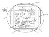
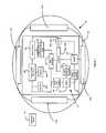
- FIG. 1illustrates an electrical block diagram of a tracking device in accordance with an embodiment of the present invention.
- FIG. 2Aillustrates a perspective top view of a mold tool to produce an electronic package for an electrical component in accordance with an embodiment of the present invention.
- FIG. 2Billustrates a side view of a mold tool to inject a thermoplastic resin into a first fill area in accordance with an embodiment of the present invention.
- FIG. 2Cillustrates a side view of a mold tool to inject a thermoplastic resin into a second fill area in accordance with an embodiment of the present invention.
- FIG. 2Dillustrates a perspective view of a PCB illustrated in FIGS. 2A-2C for electronic packaging in accordance with an embodiment of the present invention.
- FIG. 2Eillustrates a side view of an electronic package produced by molding tools shown in FIGS. 2A-2C in accordance with an embodiment of the present invention.
- FIG. 2Fillustrates a two-piece mating electronic package produced using the processing steps described with reference to FIGS. 2A-2E in accordance with an embodiment of the present invention.
- FIG. 3Aillustrates a diversity antenna located on a first side of a tracking device to support message communication in accordance with an embodiment of the present invention.
- FIG. 3Billustrates a diversity antenna located on a second side of a tracking device to support message communication in accordance with an embodiment of the present invention.
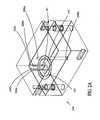
- FIG. 4Aillustrates wireless battery charging circuitry of a tracking device and an inductive charging pad in accordance with an embodiment of the present invention.
- FIG. 4Billustrates wireless battery charging circuitry of a tracking device and a dual-sided inductive charging unit in accordance with an embodiment of the present invention.
- FIG. 4Cillustrates wireless battery charging circuitry of a tracking device and a first conformal-shaped inductive charger in accordance with an embodiment of the present invention.
- FIG. 4Dillustrates wireless battery charging circuitry of a tracking device and a second conformal-shaped inductive charger in accordance with an embodiment of the present invention.
- FIG. 4Eillustrates wired battery charging connection of a tracking device in accordance with an embodiment of the present invention.
- FIG. 5illustrates a flow chart of the injection molding process in accordance with one embodiment of the present invention.
- FIG. 6illustrates a flow chart to manage battery power usage of a tracking device in accordance with one embodiment of the present invention.
- location coordinatesrefer without limitation to any set or partial set of integer, real and/or complex location data or information such as longitudinal, latitudinal, and elevational positional coordinates.
- tracking devicerefers to without limitation to any hybrid electronic circuit, integrated circuit (IC), chip, chip set, system-on-a-chip, microwave integrated circuit (MIC), Monolithic Microwave Integrated Circuit (MMIC), low noise amplifier, power amplifier, transceiver, receiver, transmitter and Application Specific Integrated Circuit (ASIC) that may be constructed and/or fabricated.
- the chip or ICmay be constructed (“fabricated”) on a small rectangle (a “die”) cut from, for example, a Silicon (or special applications, Sapphire), Gallium Arsenide, or Indium Phosphide wafer.
- the ICmay be classified, for example, into analogue, digital, or hybrid (both analogue and digital on the same chip and/or analog-to-digital converter).
- Digital integrated circuitsmay contain anything from one to millions of logic gates, invertors, and, or, nand, and nor gates, flipflops, multiplexors, etc. on a few square millimeters.
- the small size of these circuitsallows high speed, low power dissipation, and reduced manufacturing cost compared with board-level integration.
- wireless data transferrefers without limitation to any wireless system that transfers and/or determines location coordinates using one or more devices, such as Global Positioning System (GPS).
- GPSGlobal Positioning System
- Global Positioning Systemrefer to without limitation to any services, methods or devices that utilize GPS technology that determine a position of a GPS receiver based on measuring signal transfer times between satellites having known positions and the GPS receiver.
- the signal transfer time of a signalis proportional to a distance of a respective satellite from the GPS receiver.
- the distance between a satellite and a GPS receivermay be converted, utilizing signal propagation velocity, into a respective signal transfer time.
- the positional information of the GPS receiveris calculated based on distance calculations from at least four satellites to determine positional information of the GPS receiver.
- wireless networkrefers to, without limitation, any digital, analog, microwave, and millimeter wave communication networks that transfer signals from one location to another location, such as IEEE 802.11g, Bluetooth, WiMax, IS-95, GSM, IS-95, CGM, CDMA, wCDMA, PDC, UMTS, TDMA, and FDMA, or any combinations thereof.
- the present inventiondiscloses an apparatus and method of providing an electronic packaging apparatus using an injection molding process to manufacture a substantially shockproof, waterproof unit for a tracking device.
- the unitprovides a diversity antenna capable of improving receiver sensitivity.
- the unitprevents unauthorized reverse engineering of electronic components contained therein.
- inductive circuitryenables near-field wireless charging and data communication between a tracking device and a battery charger and/or a remote monitoring station to potentially improve user ease of use and decrease a user's communication costs.
- the present inventiongenerally provides packaging of tracking devices for locating and tracking an individual or an object.
- the package of the present inventionis substantially durable in nature to withstand harsh environmental conditions and/or hard surface impacts that may occur before location is determined of a missing, lost, or abducted person, Alzheimer's syndrome patient, mentally ill person, or a criminal by a guardian or law enforcement authority.
- the present inventionmay be used to provide a package for a tracking device concealed on an individual in one (or more) form factor(s).
- Form factorsmay include a pen carried in a pocket or backpack, an inner surface of a shoe, a button, a necklace, a toy, a shirt collar, and decoration, fabric of a jacket or sweater, or the like.
- Various device skinsare available to camouflage a tracking device.
- a device skinsuch as a plastic sticker or housing, attaches to a tracking device to blend a tracking device appearance with that of an object or individual to prevent discovery by an abductor (as compared to being incorporated as part of a conspicuous device, e.g., a mobile phone, pager, personal data assistant).
- the tracking devicemay be a personal locator device implanted under an individual's skin.
- the personal locating devicemay, in one example, have capability of inductively charging its battery, for instance, utilizing an inductive charging technology, methodology or apparatus described supra in FIGS. 4A-4D .
- a battery of a personal locator tracking devicemay be trickle-charged in response to an individual movement's (e.g. using technology similar to a flashlight that charges its battery level in response to user providing a shaking or back and forth motion to the flashlight).
- the present inventiondiscloses, in one embodiment, a substantially waterproof and shockproof device and, in one instance, substantially sealed and having no exposed metal contacts. Consequently, if the tracking device is submerged in water (such as when the tracking device is inadvertently washed in a washing machine as part of laundry) or exposed to cold temperature conditions, e.g., snow, the device remains functional.
- the tracking devicemay also find use monitoring and locating lost or stolen animals and objects, such as vehicles, goods and merchandise. Please note that the following discussions of manufacturing a tracking device to monitor and locate individuals is non-limiting and the present invention may be useful in other electronic packaging applications, such as watches, calculators, clocks, computer keyboards, computer mice, mobile phones and the like.
- FIGS. 1-5exemplary embodiments of the electronic packaging system of the invention are described in detail. It will be appreciated that while described primarily in the context of tracking individuals or objects, at least portions of the apparatus and methods described herein may be used in other applications, such as, utilized, without limitation, for control systems that monitor components such as transducers, sensors, and electrical and/or optical components that are part of an assembly line process. Moreover, it will be recognized that the present invention may find utility beyond purely tracking and monitoring concerns. Myriad of other functions will be recognized by those of ordinary skill in the art given the present disclosure.
- the electronic components 141insert into the mold tooling 240 (depicted in FIG. 2A ).
- the electronic components 141include a signal receiver 144 , a signal transmitter 146 , and a microprocessor/logic circuit 148 .
- the electronic components 141are disposed, deposited, or mounted on a substrate (such as a circuit board (PCB) 143 ).
- the PCB 143may be manufactured from: polyacryclic (PA), polycarbonate, (PC) composite and arylonitrile-butadiene-styrene (ABS) substrates, blends or combinations thereof, or the like.
- the microprocessor/logic circuit 148is configured to store a first identification code (of the tracking device 142 ), produce a second identification code, determine location coordinates of the tracking device 142 and generate a positioning signal that contains location data (as described in U.S. patent application Ser. No. 11/753,979 filed on May 25, 2007, previously incorporated herein by reference).
- the location dataincludes longitudinal, latitudinal, and elevational position of a tracking device, current address or recent address of the tracking device, a nearby landmark to the tracking device, and the like.
- a positioning system logic circuitcalculates location data sent to the microprocessor/logic circuit 148 from a monitoring station 151 .
- Memory 1 153 a and memory 2 153 bstore operating software and data, for instance, communicated to and from the microprocessor/logic circuit 148 and/or the wireless location and tracking logic circuit 150 .
- a power level sensor 149detects a receive signal power level.
- Signal detecting circuitry 155detects a battery level of battery 154 , which may contain one or more individual units or be grouped as a single unit.
- One or more antennas 152 a , 152 bconnect, in this example, to the signal transmitter 146 and the signal receiver 144 .
- the signal transmitter 146 and the signal receiver 144may be replaced by a transceiver circuit, chip, or integrated circuit.
- the signal transmitter 146transmits a signal including location data from a tracking device 142 to the monitoring station 151 .
- the signal receiver 144receives a signal from the monitoring station 151 , for example, by wireless data transfer, e.g., wireless telephone communication or via an Internet electronic message.
- a demodulator circuit 159extracts baseband signals, for instance at 100 KHz, including tracking device configuration and software updates, as well as converts a low-frequency AC signal to a DC voltage level.
- the DC voltage levelin one example, is supplied to battery charging circuitry 157 to recharge a battery level of the battery 154 .
- the blocks 131 a - din this example, represents battery charging components (such as inductors 408 a - d described supra with reference to FIGS. 4A-4D ).
- a user of a monitoring station 151 by listening (or downloading) one or more advertisementsmay reduce and/or shift phone usage charges to another user, account, or database (as disclosed in U.S. patent application Ser. No. 11/784,400 entitled “Communication System and Method Including Dual Mode Capability” and Ser. No. 11/784,318 entitled “Communication System and Method Including Communication Billing Options” each filed on Apr. 5, 2007, herein incorporated by reference).
- a mold tool 240supports the PCB board 143 (including the electronic components 141 shown in FIG. 1 ) in accordance with an embodiment of the present invention.
- Retractable pins 256 a - dsupport the PCB 143 within the mold tooling 240 .
- the mold tooling 240in this non-limiting example, produces a tracking device 142 to conform to a desired electronic package shape, for example, a shape of a button.
- the molding tool 240in another example, forms the tracking devices 402 , 410 (from the application Ser. No. 11/753,979 incorporated previously by reference).
- dimensionality of a mold toolconforms to a desired tracking device dimensionality, e.g., a lapel pin, button, shirt collar, shoe insert, pen, belt buckle and the like.
- the mold tool 240includes one or more molds (e.g., first mold 237 a , second mold 237 b , third mold 238 a , fourth mold 238 b ) forming one or more internal cavity areas, such as molding areas 239 a , 239 b shown in FIG. 2B , 2 C, respectively.
- a plastic composite materialis flowed into the molding areas 239 a , 239 b to encapsulate, e.g., substantially seal, the tracking device 142 .
- the plastic composite materialflows through at least one of the openings 258 a , 258 b to fill, for instance, the molding area 239 a and/or the molding area 239 b .
- the PCBmay be formed by any of the following: a polycarbonate acrylic-styrene (PC/ABS), polycarbonate (PC), acrylic-styrene (ABS) chemical composition, polymer, polyurethane, polycarbonate-urethane (PCU), thermoplastic, or blends thereof.
- the plastic composite materialmay be a thermoset plastic, thermoplastic resin, polymer, polycarbonate, elastomer, urethane, urethane elastomer, polyurethane, copolymers, thermoplastic vulcanizates, thermoplastic urethanes, olefinics, copolyamides, arylonitrile-butadiene-styrene (ABS), or blends thereof.
- Processing properties of the plastic composite materialinclude melt temperature, mold temperature, mold dimensionality and injection pressure.
- the processing propertiesfor instance, depend on a manufacturing lot and material composition as well as whether electronic components 141 to encapsulate are one or more integrated circuits or a PCB 143 .
- manufacturer specificationsconform to those by Bayer Polymers, the Polymer Technology Group and the Teknor Apex Company. More specifically, urethane elastomer processing parameters include a melt temperature between 150 to 250 degrees C., a mold temperature between 30 to 45 degrees C., and an injection pressure between 30 to 50 MPa.
- a drying processmay follow opening of first mold 237 a , 237 b and/or second mold 238 a , 238 b and removal of the tracking device 142 .
- the tracking device 142substantially replicates a combined form factor of first mold 237 a , a second mold 237 b , a third mold 238 a , and fourth mold 238 b . Consequently, the tracking device 142 conforms to physical features (e.g., belt buckles, button on a shirt, inner surface of a shoe, or the like) of the mold tooling.
- one or more electronic components 141such as packaged integrated circuits, resistors and capacitors, disposed on a PCB (such as PCB 143 ) are encapsulated in the first molding process.
- a first mold 237 a and a second mold 237 bform a cavity, e.g., a first fill area 239 a , to fill a first region on the PCB 143 using a plastic composite material, e.g., selected from the materials described above.
- the first regionincludes an active region of the electronic components 141 .
- a third mold 238 a and fourth mold 238 bform a second region.
- the second regionfor instance, is a second fill area 239 b .
- the second fill area 239 bfor example, is an area about an outer region of the first filling area 339 a for filing with a plastic composite material, to further process the PCB 143 coated with a first fill area 239 a.
- an injection stepmay be required to intermediately cure the plastic composite material.
- This curing stepmay include having the composite plastic material remain in a mold until sufficient hardening occurs, or it may include a sequence of steps of actively heating or cooling the plastic composite material within or outside of the mold to achieve a desired uniformity and consistency.
- the curing stepmay be automatic due to its inherent chemical properties.
- thermoset plastic materialit may be generally advantageous to cool to hasten its solidification.
- retractable pins 256 a - dare capable of providing PCB 143 support during injection mold processing.
- injection moldmay involve a sequential or parallel arrangement of injections of one or more plastic composite materials, (e.g., chemical compositions and/or varieties of a heated thermoplastic resin) to fill areas (e.g., fill area 239 a , fill area 239 b ) on the PCB 143 .
- an integrated circuitsuch as circuits 146 , 150 depicted in FIG. 1 , are sealed in a first fill area 239 a during a first molding process.
- the first molding processmay include a plastic composite material of a first type.
- subsequent molding processessuch as a second molding process, having a second fill area 239 b , may, in one embodiment, utilize a plastic composite material of the first type or, in the alternative, a second type, e.g., optimized for a property different than the first type.
- the second fill area 239 bmay be optimized for moisture and chemical resistance properties and the first fill area 239 a may be optimized for high resistance to breakage and stress. Consequently, this invention, in one embodiment, by using multiple types, multiple level polymers, injection processing may provide custom injection tailoring on per unit area basis on the PCB 143 to achieve one or more desired electronic packaging properties.
- the electronic packaging propertiesmay include tensile strength, hardness, and flexural modulus, tear strength, coefficient of temperature expansion, flammability, brittleness, linear mold shrinkage, specific gravity and melt flow.
- this embodiment of custom tailored layering as opposed to conventional single application polymer processingprovides a tracking device having a non-uniform profile wireless communication conducting packages.
- the present processeliminates a need for first sealing an integrated circuit, e.g., before beginning an injection processing, such as requiring an integrated circuit to be packaged in a ferrite, ceramic lead package, or the like to prevent circuitry degradation.
- multiple level sealing process of an electronic circuit(such as electronic components 141 ) using the present invention provides for improved electronic package throughput and improved package performance, e.g., improved electrostatic discharge (ESD) protection for active devices, disposed in a first fill area 239 a .
- ESDelectrostatic discharge
- Still other advantages of the present processinginclude improved communication properties for electronic components, such as electronic components 141 .
- a system designerplaces signal communicating apparatus, e.g., antennas 152 a , 152 b proximate to the electrical components 141 in a first fill area.
- the signal communication apparatuse.g., antennas 152 a , 152 b may be disposed (external to the first fill area) within a second fill area 239 b .
- a usermay selectively choose a plastic composite material in the first fill area 239 a to improve wireless communication (e.g., provide increased signal isolation) for signal sensitive components.
- a usermay choose a second fill area 239 b for improve signal-reception (for instance if the signal communication apparatus (e.g., antennas 152 a , 152 b are present in this area) or to enhance other electronic properties such as filtering, tensile strength, or density modulus in a second fill area 239 b.
- the signal communication apparatuse.g., antennas 152 a , 152 b are present in this area
- other electronic propertiessuch as filtering, tensile strength, or density modulus in a second fill area 239 b.
- the second fill area 239 bmay be disposed with a metallic material forming a multiple surface patch antenna, e.g., dual patch antennas 152 a , 152 b , to improve receiver sensitivity and/or improve signal reception (see FIG. 3 for a more detailed discussion of the dual patch antenna 152 a , 152 b ).
- multiple filling areas, such as the first fill area 239 anear the electronic components 141 may be processed at a lower temperature and pressure, cooled, and impurities and air bubbles removed from the electronic components 141 .
- processing of a second fill area 239 b proximate tomay proceed at a higher temperature with minimal degradation to the integrated circuit because the first fill area 239 a forms a protective heat barrier for heat sensitive integrated circuits, e.g., circuits 146 , 150 shown in FIG. 1 .
- the first fill area 239 ahas a higher temperature resistance than a temperature capability of the integrated circuit mounted on the PCB 143 (but a lower temperature resistance than the second fill area 239 b ); therefore, the integrated circuits, e.g., circuits 146 , 150 , as shown in FIG. 1 , are protected from a higher temperature injection material, for instance, utilized to fill the second fill area 239 b , e.g., including antennas 152 a , 152 b.
- a plastic composite material mass flow rate distributionmay be realized having a more uniform distribution; thus, board materials and electrical components may be subjected to reduced tensile pressure per unit area, e.g., preventing damage, for instance, of a PCB 143 and the integrated circuits, e.g., circuits 146 , 150 .
- the present inventionadvantageously provides a lower pressure resin mass flow rate and more uniform plastic composite material application than a conventional mold tool utilizing a single injector entry, single application molding, and a single injector exit port.
- the plastic composite materialin one example, includes a filler material or weighing material, that bundles with, for example, a binder disposed in or with the plastic composite material.
- a filler materialsuch as a glass fiber, glass ball or carbon fiber being chopped and applied to the plastic composite material, e.g., such as polycarbonate and acrylonitrile-butadiene-styrene (ABS) copolymer or others listed above.
- the glass fiber or glass ballshave a low dielectric constant, e.g., approximately 2.2.
- the filler materialprovides have a low-loss tangent at signal transmission frequencies (such as at CDMA and GSM frequency ranges) to enhance electrical signal conductivity, such as for antennas 152 a , 152 b .
- the filler materialshould maintain a high tensile strength to prevent electronic package breakage if inadvertently struck against a hard or sharp surface.
- One advantage of the present invention packaging approachis the plastic composite material bonds directly to the electronics components 141 to form a tracking device 142 having an enclosed package that is substantially hermetically sealed.
- the tracking device 142if the tracking device 142 is discovered by an assailant, it would be difficult to view its internal components, because attempted removal of the plastic composite material (e.g., flowed over the PCB 143 ) would substantially destroy electronic circuits 141 .
- the electronic components 141as compared to conventional electronic packages having a lid or an encapsulated package where removal of the package causes minimal damage to any electronic components disposed therein.
- the disclosed packaging approachis resistant to failure of electronic components 141 being dropped as compared to conventional electronic packages having poor resistance to shock, vibration, moisture, and other environmental factors (e.g., snow).
- the tracking device 142may be incorporated on child's person, such as part of a shoe or in a collar of a child's shirt, that may strike an object, be accidentally placed in a clothes washing machine, or be exposed to water.
- thermoplastic resin color and/or texturemay be selected to match a particular design or pattern.
- the resin color and texturein one instance, blends or camouflages the tracking device 142 in its surroundings.
- the size, style and color of the tracking devicesuch as tracking device 142
- the tracking device 142is substantially water impermeable and resistant to environmental conditions, such as rain, snow, wind and vibration.
- Temperature sensitive electronic componentsmay include a Low Noise Amplifier (LNA), RF Transceiver unit (RF transceiver), or Central Processing Unit (CPU) produced from a heat sensitive or temperature sensitive material.
- LNALow Noise Amplifier
- RF transceiverRF Transceiver
- CPUCentral Processing Unit
- the electronic packaging process described aboveis modified to form an electronic tracking package in two mating sections, e.g., sections 264 , 266 .
- Each mating section 264 , 266is formed utilizing one plastic perform unit having a substantially identical footprint (e.g., backside, front side, thickness, and the like) of the electrical circuit board, such as PCB 143 , to insert therein except that the perform unit includes additionally dimensionality conforming to a desired shape of a mating lip 260 , or a seam 262 .
- the perform unitis removed.
- Electronics components 141populate the mating sections 264 , 266 (including the antennas 152 a , 152 b ) as well as other components.
- the mating sections 264 , 266are snapped or glued together, e.g., using a commercially available epoxy composition, along the mating lip 260 or seam 262 , to form a substantially sealed, polycarbonate electronic package.
- a multi-patch antennae.g., microstrip patch antennas 152 a , 152 b , in one example, disposed proximately to electronic package surfaces 105 , 107 .
- the microstrip patch antennas 152 a , 152 bare positioned parallel on opposing faces of the tracking device 142 .
- the microstrip patch antennas 152 a , 152 bare quarter-wave length microstrip patches deposited on an alumina substrate.
- the operating frequency range of the microstrip patch antennais 3 GHz, but may be selected to support an operating frequency range of a skyward satellite or an RF base station.
- a separation distance between parallel microstrip patch antennas 152 a , 152 bmay be approximately 0.1 Lambda (wavelength); however, the separation distance may be any distance that supports signal spatial separation between the antennas.
- a fill materialfor example, of a dielectric constant (Er) between 3 to 9 allows a decreased separation distance, e.g., to provide smaller electrical package size and provide communication signal spatial differentiation, between the microstrip patch antennas 152 a , 152 b.
- a receiver 144receives location coordinates, such as GPS coordinates, from one or more base stations or satellites, such as satellites 302 , 304 , and 306 .
- the receiver 144mounted on the tracking device 142 to measures a snapshot of a receive signal strength on patches 152 a , 152 b .
- the low noise amplifiers (LNAs) 120 a , 120 b and the receiver 144 and transmitter 146shifts to a low power state, e.g., substantially sleep state with a nominal quiescent current, to reduce current drain; therefore, tracking device battery charge is conserved.
- a Global Positioning System (GPS)/Global Positioning Radio System (GPRS) based processore.g., an NXP semiconductor GPS processor 150 (see FIG. 1 ) processes a snapshot, e.g., 10 ms to 100 ms, of raw location coordinates received from each of the patches 152 a , 152 b.
- the resulting analysis of the snapshot of raw location coordinatesdetermines which of the antennas, e.g., patches 152 a , 152 b , predict (based on previous snapshot measurements) better receiver sensitivity for future signal acquisition.
- the resulting analysis from each of the patches 152 a , 152 bprovides information on a percentage of battery power to direct to a tracking device's electrical components, e.g., LNAs 120 a , 120 b , patches 152 a , 152 b , to maximize signal directivity of the tracking device.
- the inventionprovides for shifting and/or supplying power to one or multiple antennas, e.g., first patch 152 a or the second patch 152 b , in response to a location orientation of the tracking device 142 to a monitoring tower or station, e.g., a base station or a satellite.
- a monitoring tower or statione.g., a base station or a satellite.
- one or more microstrip patch antennasmay be attached to additional sides of a tracking device (for instance if the tracking device is square or rectangular shaped) to realize further improved tracking device directivity and control and increase a receiver sensitivity to weak signals received skyward from a satellite or from a base station monitoring tower.
- the LNAs and the transceiversmay be replaced by multiple voltage or current adjustable gain or output power controlled LNAs and/or multiple voltage or current adjustable gain controlled transceiver(s).
- the adjustable gain or output power LNAs and/or transceiversmay be electrically coupled and switched into and out of a signal path of one or more of the antennas, e.g., patches 152 a , 152 b , to realize a multi-path, multigrain tracking unit with more options to increase receiver sensitivity, including attenuation of high power or adjusting a signal level communicated.
- each of the patches 152 a , 152 bmay be replaced by one or more antenna patches on the same side, e.g., a patch array antenna, to achieve additional signal acquisition control.
- the battery charger 420requires no external metal contact points, e.g., DC, RF, and AC inputs.
- the inductive charging pad 420provides a surface, e.g., horizontal surface that electrically couples to a voltage/current transformer 424 .
- Wire-wound ferrite inductive cores 408 a - d(depicted in FIG.
- a block 131 a - dare, for instance, mounted on the circuit board 143 of the tracking device 142 and are electrically coupled (e.g., using wires) to a switching circuit, e.g., demodulator 159 , and afterwards to one or rechargeable batteries, e.g., battery 154 .
- a switching circuite.g., demodulator 159
- one or rechargeable batteriese.g., battery 154 .
- inductive charging flux paths through the plastic package 142couple electromagnetic energy from one or more wire-wound inductive cores, such as ferrite cores 410 a - d , (e.g., located within an inductive charging pad 420 ) receiving electrical energy from a computer connection, e.g., USB port 426 to inductive cores 408 a - d .
- the inductive charging pad 420provides near field communication between the tracking device 142 and a computer monitoring station, such as computer 428 .
- Signal demodulator 159demodulates a low frequency signal received from magnetic flux from the inductive charging pad 420 (e.g., the low frequency signal originated from a computer connection, e.g., USB port 426 .)
- the near field communicationcommunicates periodic tracking device software updates, data downloading/uploading, and other tracking device firmware updates.
- a voltage/current transformercouples energy, for instance, from a standard AC wall outlet 418 converting a 220V output voltage level, for example, to a 15 volt voltage level.
- magnetic fluxtransfer ac flux from the inductors 410 a - d to the inductors 408 a - d .
- a demodulator circuit 159 and a battery charging circuitry 157provide a dc voltage level to the battery 154 (as shown in FIG. 1 ).
- a dual-sided inductive charging unit 430charges the tracking device 142 using multiple tracking device sides 105 , 107 to provide increased battery charging capability.
- Increased battery charging capabilityis achieved by an increased inductive flux contact between inductive components, e.g., 408 a - d , between the tracking device 142 and inductive components, e.g., 410 a - h , within the inductive charging unit 430 .
- the inductive charging unit 430includes a transformer 425 to obtain AC/DC power and/or low frequency wireless communication from a computer connection, e.g., USB ports 427 , 429 , of the computer 428 .
- inductive components 408 e - hmay be added to further increase magnetic flux between a tracking device and inductive components, e.g., 410 a - h ).
- conformal inductive chargers 432 , 434(including one conformal, ferrite core inductor 450 ), e.g., side inductive coupled units, are realized with the tracking device 142 .
- the inductive chargers 432 , 434connect through a transformer 424 to obtain AC/DC power and/or low frequency wireless communication signals.
- a tracking device 142is illustrated having an electrical connector, e.g. USB connector 438 , to charge the battery 154 when electrically coupled between a transformer 424 , e.g. through a USB connector 426 , to a computer 428 .
- a flow chart 500illustrates one example of an injection molding process (as described above in FIGS. 2A-2D ) in accordance with one embodiment of the present invention.
- step 510electronic components 141 are placed in the mold tooling 240 (see FIG. 2A ).
- step 520a thermoplastic resin is injected into the mold (as shown in FIGS. 2B and 2C ).
- step 264the electronic components 141 are enclosed by the thermoplastic resin as shown in FIGS. 2B and 2C ).
- the mold tooling 240is removed and the tracking device 142 is formed.
- the tracking device 142is tested.
- a flow chart 600illustrates a signal acquisition procedure (as described above in FIG. 3 ) in accordance with one embodiment of the present invention.
- a first patch 152 a and a second patch 153 bacquire a snapshot of receive signals.
- a processing unite.g., 148 , 150 , processes the snapshot of the receive signals.
- the processing unitcommunicates battery power management instructions to electrical components associated with the first patch 152 a and the second patch 152 a to increase receiver sensitivity, antenna directivity, and maximize battery power usage.
Landscapes
- Engineering & Computer Science (AREA)
- Manufacturing & Machinery (AREA)
- Microelectronics & Electronic Packaging (AREA)
- Mechanical Engineering (AREA)
- Computer Networks & Wireless Communication (AREA)
- Computer Hardware Design (AREA)
- Physics & Mathematics (AREA)
- General Physics & Mathematics (AREA)
- Theoretical Computer Science (AREA)
- Charge And Discharge Circuits For Batteries Or The Like (AREA)
Abstract
Description
Claims (10)
Priority Applications (8)
| Application Number | Priority Date | Filing Date | Title |
|---|---|---|---|
| US11/933,024US9111189B2 (en) | 2007-10-31 | 2007-10-31 | Apparatus and method for manufacturing an electronic package |
| PCT/US2007/086834WO2009058159A1 (en) | 2007-10-31 | 2007-12-07 | Apparatus and method for manufacturing an electronic package |
| US12/419,451US8497774B2 (en) | 2007-04-05 | 2009-04-07 | Apparatus and method for adjusting refresh rate of location coordinates of a tracking device |
| US12/534,050US8774827B2 (en) | 2007-04-05 | 2009-07-31 | Apparatus and method for generating position fix of a tracking device in accordance with a subscriber service usage profile to conserve tracking device power |
| US13/485,848US20120238291A1 (en) | 2007-10-31 | 2012-05-31 | Devices and systems for inductive transfer of electrical energy |
| US14/285,070US20140253377A1 (en) | 2007-10-31 | 2014-05-22 | Power conservation methods to update a position fix of a mobile location tracking device |
| US14/485,990US20150065167A1 (en) | 2007-04-05 | 2014-09-15 | Activating building assets based on an individual's location |
| US15/065,358US9933270B2 (en) | 2007-04-05 | 2016-03-09 | Vehicle tracking systems and methods |
Applications Claiming Priority (1)
| Application Number | Priority Date | Filing Date | Title |
|---|---|---|---|
| US11/933,024US9111189B2 (en) | 2007-10-31 | 2007-10-31 | Apparatus and method for manufacturing an electronic package |
Related Parent Applications (2)
| Application Number | Title | Priority Date | Filing Date |
|---|---|---|---|
| US11/784,400Continuation-In-PartUS20070232351A1 (en) | 1997-05-21 | 2007-04-05 | Communication system and method including dual mode capability |
| US14/285,070Continuation-In-PartUS20140253377A1 (en) | 2007-04-05 | 2014-05-22 | Power conservation methods to update a position fix of a mobile location tracking device |
Related Child Applications (4)
| Application Number | Title | Priority Date | Filing Date |
|---|---|---|---|
| US11/753,979Continuation-In-PartUS20070229350A1 (en) | 2005-02-01 | 2007-05-25 | Apparatus and Method for Providing Location Information on Individuals and Objects using Tracking Devices |
| US13/485,848ContinuationUS20120238291A1 (en) | 2007-10-31 | 2012-05-31 | Devices and systems for inductive transfer of electrical energy |
| US13/550,593Continuation-In-PartUS20130157691A1 (en) | 2007-04-05 | 2012-07-16 | System and method for creating and managing a personalized web interface for monitoring location information on individuals and objects using tracking devices |
| US14/485,990Continuation-In-PartUS20150065167A1 (en) | 2007-04-05 | 2014-09-15 | Activating building assets based on an individual's location |
Publications (2)
| Publication Number | Publication Date |
|---|---|
| US20090111393A1 US20090111393A1 (en) | 2009-04-30 |
| US9111189B2true US9111189B2 (en) | 2015-08-18 |
Family
ID=40583458
Family Applications (2)
| Application Number | Title | Priority Date | Filing Date |
|---|---|---|---|
| US11/933,024Expired - Fee RelatedUS9111189B2 (en) | 2007-04-05 | 2007-10-31 | Apparatus and method for manufacturing an electronic package |
| US13/485,848AbandonedUS20120238291A1 (en) | 2007-10-31 | 2012-05-31 | Devices and systems for inductive transfer of electrical energy |
Family Applications After (1)
| Application Number | Title | Priority Date | Filing Date |
|---|---|---|---|
| US13/485,848AbandonedUS20120238291A1 (en) | 2007-10-31 | 2012-05-31 | Devices and systems for inductive transfer of electrical energy |
Country Status (2)
| Country | Link |
|---|---|
| US (2) | US9111189B2 (en) |
| WO (1) | WO2009058159A1 (en) |
Cited By (4)
| Publication number | Priority date | Publication date | Assignee | Title |
|---|---|---|---|---|
| US20150130403A1 (en)* | 2013-11-13 | 2015-05-14 | Google Technology Holdings LLC | Battery-charging device and method of manufacturing same |
| US10771926B1 (en) | 2018-11-30 | 2020-09-08 | Peggy J. Carr | Package tracking system |
| US11246004B2 (en) | 2019-04-16 | 2022-02-08 | Milwaukee Electric Tool Corporation | Power tool geofence tracking and dashboard |
| US12272451B2 (en) | 2021-10-12 | 2025-04-08 | Medtronic, Inc. | Wireless charging of medical devices |
Families Citing this family (32)
| Publication number | Priority date | Publication date | Assignee | Title |
|---|---|---|---|---|
| AU7584298A (en)* | 1997-05-21 | 1998-12-11 | E.S.P. Communications, Inc. | System, method and apparatus for "caller only" initiated two-way wireless communication with caller generated billing |
| US7598855B2 (en) | 2005-02-01 | 2009-10-06 | Location Based Technologies, Inc. | Apparatus and method for locating individuals and objects using tracking devices |
| US20070229350A1 (en)* | 2005-02-01 | 2007-10-04 | Scalisi Joseph F | Apparatus and Method for Providing Location Information on Individuals and Objects using Tracking Devices |
| US8774827B2 (en) | 2007-04-05 | 2014-07-08 | Location Based Technologies, Inc. | Apparatus and method for generating position fix of a tracking device in accordance with a subscriber service usage profile to conserve tracking device power |
| US8497774B2 (en) | 2007-04-05 | 2013-07-30 | Location Based Technologies Inc. | Apparatus and method for adjusting refresh rate of location coordinates of a tracking device |
| US8102256B2 (en) | 2008-01-06 | 2012-01-24 | Location Based Technologies Inc. | Apparatus and method for determining location and tracking coordinates of a tracking device |
| US8224355B2 (en) | 2007-11-06 | 2012-07-17 | Location Based Technologies Inc. | System and method for improved communication bandwidth utilization when monitoring location information |
| US8244468B2 (en)* | 2007-11-06 | 2012-08-14 | Location Based Technology Inc. | System and method for creating and managing a personalized web interface for monitoring location information on individuals and objects using tracking devices |
| US8654974B2 (en)* | 2007-10-18 | 2014-02-18 | Location Based Technologies, Inc. | Apparatus and method to provide secure communication over an insecure communication channel for location information using tracking devices |
| US20100033393A1 (en)* | 2008-08-07 | 2010-02-11 | Wilocity, Ltd. | Techniques for Mounting a Millimeter Wave Antenna and a Radio Frequency Integrated Circuit Onto a PCB |
| US9572532B2 (en)* | 2009-01-23 | 2017-02-21 | Qualcomm Incorporated | Button sensor |
| WO2010132117A1 (en)* | 2009-05-13 | 2010-11-18 | American Bank Note Company | Cover and method of manufacturing the same |
| USD611898S1 (en) | 2009-07-17 | 2010-03-16 | Lin Wei Yang | Induction charger |
| USD611900S1 (en) | 2009-07-31 | 2010-03-16 | Lin Wei Yang | Induction charger |
| USD611899S1 (en) | 2009-07-31 | 2010-03-16 | Lin Wei Yang | Induction charger |
| US8294418B2 (en)* | 2010-02-03 | 2012-10-23 | ConvenientPower, Ltd. | Power transfer device and method |
| US20110199045A1 (en)* | 2010-02-15 | 2011-08-18 | Convenientpower Hk Ltd | Power transfer device and method |
| US8301077B2 (en)* | 2009-09-24 | 2012-10-30 | ConvenientPower, Ltd | Antenna network for passive and active signal enhancement |
| US9667088B2 (en)* | 2010-07-02 | 2017-05-30 | Ming-Hsiang Yeh | Double-sided bidirectional wireless power device |
| TWM393909U (en)* | 2010-07-02 | 2010-12-01 | ming-xiang Ye | Double-sided wireless charger |
| US9496925B2 (en)* | 2011-09-30 | 2016-11-15 | Nokia Technologies Oy | Method, apparatus, and computer program product for remote wireless powering and control of an electronic device |
| GB2500043A (en)* | 2012-03-08 | 2013-09-11 | David Williams | Tracking device |
| CN103944216A (en)* | 2013-10-17 | 2014-07-23 | 中国科学院计算技术研究所 | Intelligent anti-lost charging handbag and method for manufacturing intelligent anti-lost charging handbag |
| CN105899305B (en)* | 2014-01-06 | 2020-03-06 | 乌雷什股份公司 | Sterile pipeline pig with identification device |
| WO2015155288A1 (en)* | 2014-04-11 | 2015-10-15 | Stell Gmbh | Plate for a process label |
| US9818273B2 (en)* | 2014-04-27 | 2017-11-14 | Dirac Solutions, Inc. | Secure passive RFID tag with seal |
| CN104333079A (en)* | 2014-11-14 | 2015-02-04 | 海能电子(深圳)有限公司 | Terminal device with power source |
| US10091887B2 (en) | 2015-04-02 | 2018-10-02 | Tactotek Oy | Multi-material structure with embedded electronics |
| US10431382B2 (en)* | 2015-08-31 | 2019-10-01 | Apple Inc. | Printed circuit board assembly having a damping layer |
| KR102140520B1 (en)* | 2015-12-10 | 2020-08-03 | 한화정밀기계 주식회사 | The Apparatus For Selecting Best Adaptable Nozzle And Speed |
| US11083174B2 (en)* | 2017-03-24 | 2021-08-10 | Zalliant, LLC | Communication assembly for monitoring biological data of animals |
| FR3076174B1 (en)* | 2017-12-21 | 2020-01-24 | Traxxs | COATED ELECTRONIC DEVICE |
Citations (171)
| Publication number | Priority date | Publication date | Assignee | Title |
|---|---|---|---|---|
| US3924102A (en)* | 1974-05-22 | 1975-12-02 | Nicolaas W Hanekom | Apparatus for controlling temperature |
| US4218582A (en) | 1977-10-06 | 1980-08-19 | The Board Of Trustees Of The Leland Stanford Junior University | Public key cryptographic apparatus and method |
| US4850007A (en) | 1987-06-25 | 1989-07-18 | American Telephone And Telegraph Company | Telephone toll service with advertising |
| US5079541A (en) | 1990-06-04 | 1992-01-07 | Moody Thomas O | System and method for detecting movement of an infant from a secure area |
| US5127042A (en) | 1988-09-23 | 1992-06-30 | Motorola, Inc. | Cellular cordless telephone |
| US5353331A (en) | 1992-03-05 | 1994-10-04 | Bell Atlantic Network Services, Inc. | Personal communications service using wireline/wireless integration |
| US5386468A (en) | 1992-09-14 | 1995-01-31 | Fujitsu Limited | Method of registering identification number in personal communication terminal |
| US5410748A (en)* | 1991-06-04 | 1995-04-25 | Sony Corporation | Space diversity receivers |
| US5432542A (en) | 1992-08-31 | 1995-07-11 | Television Computer, Inc. | Television receiver location identification |
| US5541976A (en) | 1991-04-17 | 1996-07-30 | Telefonaktiebolaget Lm Ericsson | Communications system for integrating a paging system with cellular radio telephones |
| US5555286A (en) | 1994-01-31 | 1996-09-10 | Tendler Technologies, Inc. | Cellular phone based automatic emergency vessel/vehicle location system |
| US5565909A (en) | 1992-08-31 | 1996-10-15 | Television Computer, Inc. | Method of identifying set-top receivers |
| US5592173A (en) | 1994-07-18 | 1997-01-07 | Trimble Navigation, Ltd | GPS receiver having a low power standby mode |
| US5785181A (en) | 1995-11-02 | 1998-07-28 | Clothestrak, Inc. | Permanent RFID garment tracking system |
| JPH10325735A (en) | 1996-10-16 | 1998-12-08 | Seiko Instr Inc | Portable type gps receiver |
| US5862511A (en) | 1995-12-28 | 1999-01-19 | Magellan Dis, Inc. | Vehicle navigation system and method |
| US5876765A (en) | 1995-11-09 | 1999-03-02 | Micron Technology, Inc. | Injection molding equipment for encapsulating semiconductor die and the like |
| JPH1164480A (en) | 1997-08-12 | 1999-03-05 | Sokkia Co Ltd | GPS receiver |
| US5967841A (en) | 1995-07-05 | 1999-10-19 | Auto Splice Systems, Inc. | Continuous molded plastic components or assemblies |
| US5973599A (en) | 1997-10-15 | 1999-10-26 | Escort Memory Systems | High temperature RFID tag |
| US6088453A (en) | 1997-01-27 | 2000-07-11 | Kabushiki Kaisha Toshiba | Scheme for computing Montgomery division and Montgomery inverse realizing fast implementation |
| US6141356A (en) | 1997-11-10 | 2000-10-31 | Ameritech Corporation | System and method for distributing voice and data information over wireless and wireline networks |
| US6236365B1 (en) | 1996-09-09 | 2001-05-22 | Tracbeam, Llc | Location of a mobile station using a plurality of commercial wireless infrastructures |
| US6243039B1 (en) | 1998-04-21 | 2001-06-05 | Mci Communications Corporation | Anytime/anywhere child locator system |
| US6278370B1 (en) | 1999-11-04 | 2001-08-21 | Lowell Underwood | Child locating and tracking apparatus |
| US6300875B1 (en) | 1999-11-22 | 2001-10-09 | Mci Worldcom, Inc. | Method and apparatus for high efficiency position information reporting |
| US20010030667A1 (en) | 2000-04-10 | 2001-10-18 | Kelts Brett R. | Interactive display interface for information objects |
| US6327533B1 (en) | 2000-06-30 | 2001-12-04 | Geospatial Technologies, Inc. | Method and apparatus for continuously locating an object |
| US20010048364A1 (en) | 2000-02-23 | 2001-12-06 | Kalthoff Robert Michael | Remote-to-remote position locating system |
| US20020041328A1 (en) | 2000-03-29 | 2002-04-11 | Astrovision International, Inc. | Direct broadcast imaging satellite system apparatus and method for providing real-time, continuous monitoring of earth from geostationary earth orbit and related services |
| US6388612B1 (en) | 2000-03-26 | 2002-05-14 | Timothy J Neher | Global cellular position tracking device |
| US20020067256A1 (en) | 1997-03-07 | 2002-06-06 | Kail, Karl A. | Reprogrammable remote sensor monitoring system |
| US20020077130A1 (en) | 1998-01-21 | 2002-06-20 | Craig A. Owensby | System and method for providing targeted messages based on wireless mobile location |
| US6414629B1 (en) | 2001-04-19 | 2002-07-02 | Tektrack, Llc | Tracking device |
| US6441741B1 (en) | 1999-05-17 | 2002-08-27 | Avid Identification Systems, Inc. | Overmolded transponder |
| US6445921B1 (en) | 1999-12-20 | 2002-09-03 | Koninklijke Philips Electronics N.V. | Call re-establishment for a dual mode telephone |
| US6453037B1 (en) | 1995-04-19 | 2002-09-17 | Mci Communications Corporation | Remote telecommunications system for automatic number identification screening |
| US20020186135A1 (en) | 2001-05-30 | 2002-12-12 | Colleen Wagner | Device for locating an individual |
| US6498797B1 (en) | 1997-11-14 | 2002-12-24 | At&T Corp. | Method and apparatus for communication services on a network |
| US20020196123A1 (en) | 2001-06-26 | 2002-12-26 | The Procter & Gamble Company | Portable locking systems |
| US20030043200A1 (en) | 2001-08-09 | 2003-03-06 | Urbanpixel Inc | Interactive multi-level mapping in a multiple browser environment |
| US6546253B1 (en) | 1998-12-30 | 2003-04-08 | At&T Corp. | Neighborhood cordless service call handoff |
| US20030131073A1 (en) | 2001-03-14 | 2003-07-10 | Lucovsky Mark H. | Schema-based services for identity-based data access |
| US6611755B1 (en) | 1999-12-19 | 2003-08-26 | Trimble Navigation Ltd. | Vehicle tracking, communication and fleet management system |
| US20030177094A1 (en) | 2002-03-15 | 2003-09-18 | Needham Bradford H. | Authenticatable positioning data |
| US6633835B1 (en) | 2002-01-10 | 2003-10-14 | Networks Associates Technology, Inc. | Prioritized data capture, classification and filtering in a network monitoring environment |
| US20030208518A1 (en) | 2002-05-01 | 2003-11-06 | Sun Microsystems, Inc. | Generic implementations of ellipitic curve cryptography using partial reduction |
| US20030210262A1 (en) | 2002-05-10 | 2003-11-13 | Tripath Imaging, Inc. | Video microscopy system and multi-view virtual slide viewer capable of simultaneously acquiring and displaying various digital views of an area of interest located on a microscopic slide |
| US6654883B1 (en) | 1998-02-25 | 2003-11-25 | Matsushita Electric Industrial Co., Ltd. | Device authentication and encrypted communication system offering increased security |
| US20030235307A1 (en) | 2002-06-13 | 2003-12-25 | Kazuhiro Miyamoto | Encryption and decryption program |
| US6674368B2 (en) | 2000-08-28 | 2004-01-06 | Continental Divide Robotics, Inc. | Automated tracking system |
| US20040010689A1 (en) | 2002-05-03 | 2004-01-15 | Vanstone Scott A. | Method and apparatus for performing elliptic curve arithmetic |
| US20040021573A1 (en) | 1997-01-21 | 2004-02-05 | Hoffman Resources Llc | Personal security and tracking system |
| US6708028B1 (en) | 1993-12-22 | 2004-03-16 | Nokia Mobile Phones, Ltd. | Multi-mode radio telephone |
| US6716101B1 (en) | 2000-06-28 | 2004-04-06 | Bellsouth Intellectual Property Corporation | System and method for monitoring the location of individuals via the world wide web using a wireless communications network |
| US6732090B2 (en) | 2001-08-13 | 2004-05-04 | Xerox Corporation | Meta-document management system with user definable personalities |
| US6735630B1 (en) | 1999-10-06 | 2004-05-11 | Sensoria Corporation | Method for collecting data using compact internetworked wireless integrated network sensors (WINS) |
| US6747561B1 (en) | 2000-06-20 | 2004-06-08 | Med-Datanet, Llc | Bodily worn device for digital storage and retrieval of medical records and personal identification |
| US6754470B2 (en) | 2000-09-01 | 2004-06-22 | Telephia, Inc. | System and method for measuring wireless device and network usage and performance metrics |
| US6768942B1 (en) | 2000-09-18 | 2004-07-27 | Navigation Technologies Corp. | Navigation system with decryption functions and secure geographic database |
| US6774838B2 (en) | 2002-12-27 | 2004-08-10 | Kinpo Electronics, Inc. | Power saving device and method for GPS receiver |
| US20040165726A1 (en) | 2002-12-03 | 2004-08-26 | Masato Yamamichi | Key agreement system, shared-key generation apparatus, and shared-key recovery apparatus |
| US20040172403A1 (en) | 2002-11-26 | 2004-09-02 | Steele Rhea L. | Method and system for automated tracking of persons at remote activities |
| US20040212493A1 (en)* | 2003-02-03 | 2004-10-28 | Stilp Louis A. | RFID reader for a security network |
| US6812824B1 (en) | 1996-10-17 | 2004-11-02 | Rf Technologies, Inc. | Method and apparatus combining a tracking system and a wireless communication system |
| US6819247B2 (en) | 2001-02-16 | 2004-11-16 | Locast Corporation | Apparatus, method, and system for remote monitoring of need for assistance based on change in velocity |
| US6833787B1 (en) | 1999-10-07 | 2004-12-21 | Asap Software Express, Inc. | Method and system for device tracking |
| US6850252B1 (en) | 1999-10-05 | 2005-02-01 | Steven M. Hoffberg | Intelligent electronic appliance system and method |
| US20050024201A1 (en) | 2003-08-01 | 2005-02-03 | Spectrum Tracking Systems, Inc. | Method for locating an asset |
| US6859533B1 (en) | 1999-04-06 | 2005-02-22 | Contentguard Holdings, Inc. | System and method for transferring the right to decode messages in a symmetric encoding scheme |
| US20050044356A1 (en) | 1999-12-22 | 2005-02-24 | Sunil Srivastava | Method and apparatus for distributing and updating private keys of multicast group managers using directory replication |
| US20050071736A1 (en) | 2003-09-26 | 2005-03-31 | Fuji Xerox Co., Ltd. | Comprehensive and intuitive media collection and management tool |
| US20050071282A1 (en) | 2003-09-29 | 2005-03-31 | Lu Hongqian Karen | System and method for preventing identity theft using a secure computing device |
| US6879244B1 (en) | 1997-05-21 | 2005-04-12 | E.S.P. Networks, Inc. | Call receiving system apparatus and method having a dedicated switch |
| US6882897B1 (en) | 2004-01-05 | 2005-04-19 | Dennis S. Fernandez | Reconfigurable garment definition and production method |
| US20050099303A1 (en) | 2003-11-11 | 2005-05-12 | Zuckerman Andrew M. | Injection molded garment hanger |
| US20050113124A1 (en) | 2003-11-26 | 2005-05-26 | Jari Syrjarinne | Method and apparatus for lowering power use by a ranging receiver |
| US20050145688A1 (en) | 2003-12-29 | 2005-07-07 | Milan Milenkovic | Asset management methods and apparatus |
| US20050159883A1 (en) | 2004-01-16 | 2005-07-21 | Worldcom, Inc. | Method and system for tracked device location and route adherence via geofencing |
| US6928280B1 (en) | 2000-03-20 | 2005-08-09 | Telephia, Inc. | Method and system for measuring data quality of service in a wireless network using multiple remote units and a back end processor |
| US20050181870A1 (en)* | 2004-02-12 | 2005-08-18 | Igt | Player verification method and system for remote gaming terminals |
| US20050188403A1 (en) | 2004-02-23 | 2005-08-25 | Kotzin Michael D. | System and method for presenting and editing customized media streams to a content providing device |
| US6937726B1 (en) | 1999-04-06 | 2005-08-30 | Contentguard Holdings, Inc. | System and method for protecting data files by periodically refreshing a decryption key |
| US20050210260A1 (en) | 2004-03-17 | 2005-09-22 | Ramarathnam Venkatesan | Unimodular matrix-based message authentication codes (MAC) |
| US20050246647A1 (en) | 2004-04-30 | 2005-11-03 | Microsoft Corporation | System and method for selecting a view mode using a control including a graphical depiction of the view mode |
| US20050248459A1 (en) | 2001-07-10 | 2005-11-10 | American Express Marketing & Development Corp. | A system and method for providing an rfid transaction device |
| US6975941B1 (en) | 2002-04-24 | 2005-12-13 | Chung Lau | Method and apparatus for intelligent acquisition of position information |
| US6978021B1 (en) | 2000-09-18 | 2005-12-20 | Navteq North America, Llc | Encryption method for distribution of data |
| US20060009152A1 (en) | 2004-07-06 | 2006-01-12 | International Business Machines Corporation | Method and application for automatic tracking of mobile devices for computer network processor systems |
| US6988026B2 (en) | 1995-06-07 | 2006-01-17 | Automotive Technologies International Inc. | Wireless and powerless sensor and interrogator |
| US6992584B2 (en) | 2001-01-23 | 2006-01-31 | Koninklijke Philips Electronics N.V. | Mobile device comprising a GPS receiver |
| US6998995B2 (en) | 2001-09-28 | 2006-02-14 | Toshiba Elevator Kabushiki Kaisha | Elevator remote monitoring apparatus |
| US6998985B2 (en) | 2003-03-05 | 2006-02-14 | Dmatek, Ltd. | Monitoring and tracking network |
| US7020701B1 (en) | 1999-10-06 | 2006-03-28 | Sensoria Corporation | Method for collecting and processing data using internetworked wireless integrated network sensors (WINS) |
| US20060084420A1 (en) | 2004-09-30 | 2006-04-20 | Smith Brian J | Method and integrated system for networked control of an environment of a mobile object |
| US7049957B2 (en) | 2000-11-03 | 2006-05-23 | Wcr Company | Local area positioning system |
| US7065348B1 (en) | 2000-09-28 | 2006-06-20 | Kabushiki Kaisha Toshiba | Communication system for providing information on position of communication party |
| US7065244B2 (en) | 2002-07-12 | 2006-06-20 | Laurence A. Boyd | Method of mapping a three dimensional area |
| US7065370B2 (en) | 2001-09-06 | 2006-06-20 | Sony Corporation | Positioning information transmitting device and positioning information transmitting/receiving system |
| US7064711B2 (en) | 2003-04-09 | 2006-06-20 | Siemens Aktiengesellschaft | Method for iterative determination of distance between receiving station and transmitting station and also calculating unit and computer software product |
| US7079650B1 (en) | 1999-07-09 | 2006-07-18 | Oberthur Card Systems Sa | Computing method for elliptic curve cryptography |
| US20060161377A1 (en) | 2004-12-30 | 2006-07-20 | Juha Rakkola | Low power motion detector |
| US7088242B2 (en) | 2003-09-16 | 2006-08-08 | International Business Machines Corporation | Collective personal articles tracking |
| US7088252B2 (en) | 2004-06-10 | 2006-08-08 | David Weekes | Systems and apparatus for personal security |
| US7099921B1 (en) | 2000-10-16 | 2006-08-29 | Hall Aluminum Llc | Method and apparatus for people to simply communicate their location and activity information |
| US20060206246A1 (en) | 2004-10-28 | 2006-09-14 | Walker Richard C | Second national / international management and security system for responsible global resourcing through technical management to brige cultural and economic desparity |
| US20060205416A1 (en) | 2005-03-14 | 2006-09-14 | Kayzar Brett A | Push-to-locate wireless communication device and method of use |
| US7119669B2 (en) | 2003-12-16 | 2006-10-10 | Motorola, Inc. | Method and apparatus for detecting vehicular collisions |
| US7120928B2 (en) | 2001-06-15 | 2006-10-10 | Dinesh Sheth | Secure selective sharing of account information on an internet information aggregation system |
| US20060232449A1 (en) | 2005-04-18 | 2006-10-19 | Microsoft Corporation | Retention of information about digital-media rights in transformed digital media content |
| US20060253590A1 (en) | 2005-04-08 | 2006-11-09 | Konaware, Inc. | Platform and methods for continuous asset location tracking and monitoring in intermittently connected environments |
| US7139396B2 (en) | 2002-06-27 | 2006-11-21 | Microsoft Corporation | Koblitz exponentiation with bucketing |
| US7146367B2 (en) | 2002-05-14 | 2006-12-05 | Advectis, Inc. | Document management system and method |
| US7149189B2 (en) | 2001-07-17 | 2006-12-12 | Mcafee, Inc. | Network data retrieval and filter systems and methods |
| US7155238B2 (en) | 2004-07-06 | 2006-12-26 | Katz Daniel A | Wireless location determining device |
| US20060290497A1 (en) | 2003-08-22 | 2006-12-28 | Sugata T | Fastener and securement subject having the fastener secured thereto |
| US7158912B2 (en) | 1994-11-21 | 2007-01-02 | Phatrath Technology, Llc | Mobile GPS systems for providing location mapping and/or performance data |
| US20070028088A1 (en) | 2005-08-01 | 2007-02-01 | Coskun Bayrak | Polymorphic encryption method and system |
| US20070033531A1 (en) | 2005-08-04 | 2007-02-08 | Christopher Marsh | Method and apparatus for context-specific content delivery |
| US7181192B2 (en) | 2004-03-16 | 2007-02-20 | Texas Instruments Incorporated | Handheld portable automatic emergency alert system and method |
| US20070054530A1 (en) | 2005-09-02 | 2007-03-08 | Michael Bauer | Plastic housing composition for embedding semicondutor devices in a plastic housing and use of the plastic housing composition |
| US20070057068A1 (en) | 2005-09-14 | 2007-03-15 | Hsin-Feng Tsai | Portable electronic device and method for automatically switching power modes |
| US20070061303A1 (en) | 2005-09-14 | 2007-03-15 | Jorey Ramer | Mobile search result clustering |
| US20070073719A1 (en) | 2005-09-14 | 2007-03-29 | Jorey Ramer | Physical navigation of a mobile search application |
| US7200673B1 (en) | 2000-06-09 | 2007-04-03 | Steven Augart | Determining the geographic location of a network device |
| US20070083819A1 (en) | 2005-10-12 | 2007-04-12 | Idelix Software Inc. | Method and system for generating pyramid fisheye lens detail-in-context presentations |
| US20070103296A1 (en) | 2005-10-11 | 2007-05-10 | Snif Labs, Inc. | Tag system |
| US20070159322A1 (en) | 2005-10-29 | 2007-07-12 | Garratt Campbell Thomas R | Location, tracking and alerting apparatus and method |
| US7246007B2 (en) | 2004-03-24 | 2007-07-17 | General Motors Corporation | System and method of communicating traffic information |
| US7257836B1 (en) | 2000-04-24 | 2007-08-14 | Microsoft Corporation | Security link management in dynamic networks |
| US7268700B1 (en) | 1998-01-27 | 2007-09-11 | Hoffberg Steven M | Mobile communication device |
| US7272212B2 (en) | 1999-09-13 | 2007-09-18 | Microstrategy, Incorporated | System and method for the creation and automatic deployment of personalized, dynamic and interactive voice services |
| US7272662B2 (en) | 2000-11-30 | 2007-09-18 | Nms Communications Corporation | Systems and methods for routing messages to communications devices over a communications network |
| WO2007107022A1 (en) | 2006-03-21 | 2007-09-27 | Habasit Ag | Modular conveyor belt with rfid |
| US20070229350A1 (en) | 2005-02-01 | 2007-10-04 | Scalisi Joseph F | Apparatus and Method for Providing Location Information on Individuals and Objects using Tracking Devices |
| US7284191B2 (en) | 2001-08-13 | 2007-10-16 | Xerox Corporation | Meta-document management system with document identifiers |
| US20070255620A1 (en) | 2006-03-30 | 2007-11-01 | Obopay Inc. | Transacting Mobile Person-to-Person Payments |
| US7292223B2 (en) | 2000-02-24 | 2007-11-06 | Innalabs Technologies, Inc. | Location tracking device |
| US7299277B1 (en) | 2002-01-10 | 2007-11-20 | Network General Technology | Media module apparatus and method for use in a network monitoring environment |
| US20070287473A1 (en) | 1998-11-24 | 2007-12-13 | Tracbeam Llc | Platform and applications for wireless location and other complex services |
| US20070288427A1 (en) | 2005-09-14 | 2007-12-13 | Jorey Ramer | Mobile pay-per-call campaign creation |
| US20070285247A1 (en)* | 2004-06-22 | 2007-12-13 | Forster Ian J | RFID Tags for Enabling Batch Reading of Stacks of Cartons |
| US7313825B2 (en) | 2000-11-13 | 2007-12-25 | Digital Doors, Inc. | Data security system and method for portable device |
| US20080010585A1 (en) | 2003-09-26 | 2008-01-10 | Fuji Xerox Co., Ltd. | Binding interactive multichannel digital document system and authoring tool |
| US20080028063A1 (en) | 2006-07-28 | 2008-01-31 | Microsoft Corporation | Presence-based Location and/or Proximity Awareness |
| US20080059504A1 (en) | 2005-11-30 | 2008-03-06 | Jackie Barbetta | Method and system for rendering graphical user interface |
| US20080059889A1 (en) | 2006-09-01 | 2008-03-06 | Cheryl Parker | System and Method of Overlaying and Integrating Data with Geographic Mapping Applications |
| US20080088437A1 (en) | 2005-05-06 | 2008-04-17 | Omnilink Systems, Inc. | System and method for monitoring alarms and responding to the movement of individuals and assets |
| US20080108370A1 (en) | 2005-04-06 | 2008-05-08 | Steve Aninye | System and Method for Tracking, Monitoring, Collecting, Reporting and Communicating with the Movement of Individuals |
| US20080109762A1 (en) | 2006-11-03 | 2008-05-08 | Microsoft Corporation | Visual document user interface system |
| US20080129491A1 (en) | 2006-10-26 | 2008-06-05 | Netzer Arias Ruperto | Find And See Application For A Group Of Devices |
| US20080171559A1 (en) | 2006-05-12 | 2008-07-17 | Bellsouth Intellectual Property Corporation | Location-Based Alerting |
| US20080172173A1 (en) | 2007-01-17 | 2008-07-17 | Microsoft Corporation | Location mapping for key-point based services |
| US20080228654A1 (en) | 2007-03-12 | 2008-09-18 | Qualcomm Incorporated | Network independent location services |
| US20080252459A1 (en)* | 2005-12-09 | 2008-10-16 | Butler Timothy P | Methods and systems of a multiple radio frequency network node rfid tag |
| US20080252254A1 (en)* | 2006-08-31 | 2008-10-16 | Semiconductor Energy Laboratory Co., Ltd. | Power storage device and semiconductor device provided with the power storage device |
| US7501984B2 (en)* | 2003-11-04 | 2009-03-10 | Avery Dennison Corporation | RFID tag using a surface insensitive antenna structure |
| US20090098857A1 (en) | 2007-10-10 | 2009-04-16 | Dallas De Atley | Securely Locating a Device |
| US20090098903A1 (en) | 2006-08-31 | 2009-04-16 | Palm, Inc. | Using wireless characteristic to trigger generation of position fix |
| US20090103722A1 (en) | 2007-10-18 | 2009-04-23 | Anderson Roger B | Apparatus and method to provide secure communication over an insecure communication channel for location information using tracking devices |
| US20090117921A1 (en) | 2007-11-06 | 2009-05-07 | Beydler Michael L | System and method for improved communication bandwidth utilization when monitoring location information |
| US20090119119A1 (en) | 2007-11-06 | 2009-05-07 | Scalisi Joseph F | System and method for creating and managing a personalized web interface for monitoring location information on individuals and objects using tracking devices |
| US20090174603A1 (en) | 2008-01-06 | 2009-07-09 | Scalisi Joseph F | Apparatus and method for determining location and tracking coordinates of a tracking device |
| US20090177385A1 (en) | 2008-01-06 | 2009-07-09 | Apple Inc. | Graphical user interface for presenting location information |
| US20090189807A1 (en) | 2007-04-05 | 2009-07-30 | Scalisi Joseph F | Apparatus and method for adjusting refresh rate of location coordinates of a tracking device |
| US7598855B2 (en) | 2005-02-01 | 2009-10-06 | Location Based Technologies, Inc. | Apparatus and method for locating individuals and objects using tracking devices |
| US7612663B2 (en) | 2005-12-23 | 2009-11-03 | Kinpo Electrnics, Inc. | Power saving device for GPS device |
| US7626499B2 (en) | 2004-04-29 | 2009-12-01 | Burneske Gregory W | Tracking system and methods thereof |
| US20090315767A1 (en) | 2007-04-05 | 2009-12-24 | Scalisi Joseph F | Apparatus and method for generating position fix of a tracking device in accordance with a subscriber service usage profile to conserve tracking device power |
| US7728724B1 (en) | 2005-02-01 | 2010-06-01 | Location Based Technologies, Inc. | System for locating individuals and objects |
| US7995994B2 (en) | 2006-09-22 | 2011-08-09 | Kineto Wireless, Inc. | Method and apparatus for preventing theft of service in a communication system |
Family Cites Families (1)
| Publication number | Priority date | Publication date | Assignee | Title |
|---|---|---|---|---|
| US7843335B2 (en)* | 2007-03-13 | 2010-11-30 | Blackbird Technologies, Inc. | Mobile asset tracking unit, system and method |
- 2007
- 2007-10-31USUS11/933,024patent/US9111189B2/ennot_activeExpired - Fee Related
- 2007-12-07WOPCT/US2007/086834patent/WO2009058159A1/enactiveApplication Filing
- 2012
- 2012-05-31USUS13/485,848patent/US20120238291A1/ennot_activeAbandoned
Patent Citations (187)
| Publication number | Priority date | Publication date | Assignee | Title |
|---|---|---|---|---|
| US3924102A (en)* | 1974-05-22 | 1975-12-02 | Nicolaas W Hanekom | Apparatus for controlling temperature |
| US4218582A (en) | 1977-10-06 | 1980-08-19 | The Board Of Trustees Of The Leland Stanford Junior University | Public key cryptographic apparatus and method |
| US4850007A (en) | 1987-06-25 | 1989-07-18 | American Telephone And Telegraph Company | Telephone toll service with advertising |
| US5127042A (en) | 1988-09-23 | 1992-06-30 | Motorola, Inc. | Cellular cordless telephone |
| US5079541A (en) | 1990-06-04 | 1992-01-07 | Moody Thomas O | System and method for detecting movement of an infant from a secure area |
| US5541976A (en) | 1991-04-17 | 1996-07-30 | Telefonaktiebolaget Lm Ericsson | Communications system for integrating a paging system with cellular radio telephones |
| US5410748A (en)* | 1991-06-04 | 1995-04-25 | Sony Corporation | Space diversity receivers |
| US5353331A (en) | 1992-03-05 | 1994-10-04 | Bell Atlantic Network Services, Inc. | Personal communications service using wireline/wireless integration |
| US5432542A (en) | 1992-08-31 | 1995-07-11 | Television Computer, Inc. | Television receiver location identification |
| US5565909A (en) | 1992-08-31 | 1996-10-15 | Television Computer, Inc. | Method of identifying set-top receivers |
| US5386468A (en) | 1992-09-14 | 1995-01-31 | Fujitsu Limited | Method of registering identification number in personal communication terminal |
| US6708028B1 (en) | 1993-12-22 | 2004-03-16 | Nokia Mobile Phones, Ltd. | Multi-mode radio telephone |
| US5555286A (en) | 1994-01-31 | 1996-09-10 | Tendler Technologies, Inc. | Cellular phone based automatic emergency vessel/vehicle location system |
| US5592173A (en) | 1994-07-18 | 1997-01-07 | Trimble Navigation, Ltd | GPS receiver having a low power standby mode |
| US7158912B2 (en) | 1994-11-21 | 2007-01-02 | Phatrath Technology, Llc | Mobile GPS systems for providing location mapping and/or performance data |
| US6453037B1 (en) | 1995-04-19 | 2002-09-17 | Mci Communications Corporation | Remote telecommunications system for automatic number identification screening |
| US6988026B2 (en) | 1995-06-07 | 2006-01-17 | Automotive Technologies International Inc. | Wireless and powerless sensor and interrogator |
| US5967841A (en) | 1995-07-05 | 1999-10-19 | Auto Splice Systems, Inc. | Continuous molded plastic components or assemblies |
| US5785181A (en) | 1995-11-02 | 1998-07-28 | Clothestrak, Inc. | Permanent RFID garment tracking system |
| US5876765A (en) | 1995-11-09 | 1999-03-02 | Micron Technology, Inc. | Injection molding equipment for encapsulating semiconductor die and the like |
| US5862511A (en) | 1995-12-28 | 1999-01-19 | Magellan Dis, Inc. | Vehicle navigation system and method |
| US6952181B2 (en) | 1996-09-09 | 2005-10-04 | Tracbeam, Llc | Locating a mobile station using a plurality of wireless networks and applications therefor |
| US6236365B1 (en) | 1996-09-09 | 2001-05-22 | Tracbeam, Llc | Location of a mobile station using a plurality of commercial wireless infrastructures |
| JPH10325735A (en) | 1996-10-16 | 1998-12-08 | Seiko Instr Inc | Portable type gps receiver |
| US6812824B1 (en) | 1996-10-17 | 2004-11-02 | Rf Technologies, Inc. | Method and apparatus combining a tracking system and a wireless communication system |
| US20040021573A1 (en) | 1997-01-21 | 2004-02-05 | Hoffman Resources Llc | Personal security and tracking system |
| US7038590B2 (en) | 1997-01-21 | 2006-05-02 | Hoffman Recruiters Llc | Personal security and tracking system |
| US6088453A (en) | 1997-01-27 | 2000-07-11 | Kabushiki Kaisha Toshiba | Scheme for computing Montgomery division and Montgomery inverse realizing fast implementation |
| US20020067256A1 (en) | 1997-03-07 | 2002-06-06 | Kail, Karl A. | Reprogrammable remote sensor monitoring system |
| US7218242B2 (en) | 1997-05-21 | 2007-05-15 | Pocketfinder Inc. | Communication system and method including communication channel mobility |
| US6879244B1 (en) | 1997-05-21 | 2005-04-12 | E.S.P. Networks, Inc. | Call receiving system apparatus and method having a dedicated switch |
| US20080090550A1 (en) | 1997-05-21 | 2008-04-17 | Pocketfinder Inc. | Communication system and method including communication billing options |
| US20060211405A1 (en) | 1997-05-21 | 2006-09-21 | Pocketfinder Inc. | Call receiving system apparatus and method having a dedicated switch |
| JPH1164480A (en) | 1997-08-12 | 1999-03-05 | Sokkia Co Ltd | GPS receiver |
| US5973599A (en) | 1997-10-15 | 1999-10-26 | Escort Memory Systems | High temperature RFID tag |
| US6141356A (en) | 1997-11-10 | 2000-10-31 | Ameritech Corporation | System and method for distributing voice and data information over wireless and wireline networks |
| US6498797B1 (en) | 1997-11-14 | 2002-12-24 | At&T Corp. | Method and apparatus for communication services on a network |
| US20020077130A1 (en) | 1998-01-21 | 2002-06-20 | Craig A. Owensby | System and method for providing targeted messages based on wireless mobile location |
| US7268700B1 (en) | 1998-01-27 | 2007-09-11 | Hoffberg Steven M | Mobile communication device |
| US6654883B1 (en) | 1998-02-25 | 2003-11-25 | Matsushita Electric Industrial Co., Ltd. | Device authentication and encrypted communication system offering increased security |
| US6243039B1 (en) | 1998-04-21 | 2001-06-05 | Mci Communications Corporation | Anytime/anywhere child locator system |
| US20070287473A1 (en) | 1998-11-24 | 2007-12-13 | Tracbeam Llc | Platform and applications for wireless location and other complex services |
| US6546253B1 (en) | 1998-12-30 | 2003-04-08 | At&T Corp. | Neighborhood cordless service call handoff |
| US6859533B1 (en) | 1999-04-06 | 2005-02-22 | Contentguard Holdings, Inc. | System and method for transferring the right to decode messages in a symmetric encoding scheme |
| US6937726B1 (en) | 1999-04-06 | 2005-08-30 | Contentguard Holdings, Inc. | System and method for protecting data files by periodically refreshing a decryption key |
| US20020180602A1 (en) | 1999-05-17 | 2002-12-05 | Jay Yoakum | Overmolded transponder |
| US6441741B1 (en) | 1999-05-17 | 2002-08-27 | Avid Identification Systems, Inc. | Overmolded transponder |
| US7109868B2 (en) | 1999-05-17 | 2006-09-19 | Avid Identification Systems, Inc. | Unitary core transponder |
| US20050012620A1 (en) | 1999-05-17 | 2005-01-20 | Jay Yoakum | Unitary core transponder |
| US6778089B2 (en) | 1999-05-17 | 2004-08-17 | Avid Identification Systems, Inc. | Overmolded transponder |
| US7079650B1 (en) | 1999-07-09 | 2006-07-18 | Oberthur Card Systems Sa | Computing method for elliptic curve cryptography |
| US7272212B2 (en) | 1999-09-13 | 2007-09-18 | Microstrategy, Incorporated | System and method for the creation and automatic deployment of personalized, dynamic and interactive voice services |
| US20070053513A1 (en) | 1999-10-05 | 2007-03-08 | Hoffberg Steven M | Intelligent electronic appliance system and method |
| US6850252B1 (en) | 1999-10-05 | 2005-02-01 | Steven M. Hoffberg | Intelligent electronic appliance system and method |
| US6735630B1 (en) | 1999-10-06 | 2004-05-11 | Sensoria Corporation | Method for collecting data using compact internetworked wireless integrated network sensors (WINS) |
| US7020701B1 (en) | 1999-10-06 | 2006-03-28 | Sensoria Corporation | Method for collecting and processing data using internetworked wireless integrated network sensors (WINS) |
| US6833787B1 (en) | 1999-10-07 | 2004-12-21 | Asap Software Express, Inc. | Method and system for device tracking |
| US6278370B1 (en) | 1999-11-04 | 2001-08-21 | Lowell Underwood | Child locating and tracking apparatus |
| US6300875B1 (en) | 1999-11-22 | 2001-10-09 | Mci Worldcom, Inc. | Method and apparatus for high efficiency position information reporting |
| US6611755B1 (en) | 1999-12-19 | 2003-08-26 | Trimble Navigation Ltd. | Vehicle tracking, communication and fleet management system |
| US6445921B1 (en) | 1999-12-20 | 2002-09-03 | Koninklijke Philips Electronics N.V. | Call re-establishment for a dual mode telephone |
| US20050044356A1 (en) | 1999-12-22 | 2005-02-24 | Sunil Srivastava | Method and apparatus for distributing and updating private keys of multicast group managers using directory replication |
| US20010048364A1 (en) | 2000-02-23 | 2001-12-06 | Kalthoff Robert Michael | Remote-to-remote position locating system |
| US7292223B2 (en) | 2000-02-24 | 2007-11-06 | Innalabs Technologies, Inc. | Location tracking device |
| US6928280B1 (en) | 2000-03-20 | 2005-08-09 | Telephia, Inc. | Method and system for measuring data quality of service in a wireless network using multiple remote units and a back end processor |
| US6388612B1 (en) | 2000-03-26 | 2002-05-14 | Timothy J Neher | Global cellular position tracking device |
| US20020041328A1 (en) | 2000-03-29 | 2002-04-11 | Astrovision International, Inc. | Direct broadcast imaging satellite system apparatus and method for providing real-time, continuous monitoring of earth from geostationary earth orbit and related services |
| US20010030667A1 (en) | 2000-04-10 | 2001-10-18 | Kelts Brett R. | Interactive display interface for information objects |
| US7257836B1 (en) | 2000-04-24 | 2007-08-14 | Microsoft Corporation | Security link management in dynamic networks |
| US7200673B1 (en) | 2000-06-09 | 2007-04-03 | Steven Augart | Determining the geographic location of a network device |
| US6747561B1 (en) | 2000-06-20 | 2004-06-08 | Med-Datanet, Llc | Bodily worn device for digital storage and retrieval of medical records and personal identification |
| US6716101B1 (en) | 2000-06-28 | 2004-04-06 | Bellsouth Intellectual Property Corporation | System and method for monitoring the location of individuals via the world wide web using a wireless communications network |
| US20040166879A1 (en) | 2000-06-28 | 2004-08-26 | Vernon Meadows | System and method for monitoring the location of individuals via the world wide web using a wireless communications network |
| US6327533B1 (en) | 2000-06-30 | 2001-12-04 | Geospatial Technologies, Inc. | Method and apparatus for continuously locating an object |
| US6674368B2 (en) | 2000-08-28 | 2004-01-06 | Continental Divide Robotics, Inc. | Automated tracking system |
| US6754470B2 (en) | 2000-09-01 | 2004-06-22 | Telephia, Inc. | System and method for measuring wireless device and network usage and performance metrics |
| US6978021B1 (en) | 2000-09-18 | 2005-12-20 | Navteq North America, Llc | Encryption method for distribution of data |
| US6768942B1 (en) | 2000-09-18 | 2004-07-27 | Navigation Technologies Corp. | Navigation system with decryption functions and secure geographic database |
| US7065348B1 (en) | 2000-09-28 | 2006-06-20 | Kabushiki Kaisha Toshiba | Communication system for providing information on position of communication party |
| US7099921B1 (en) | 2000-10-16 | 2006-08-29 | Hall Aluminum Llc | Method and apparatus for people to simply communicate their location and activity information |
| US7049957B2 (en) | 2000-11-03 | 2006-05-23 | Wcr Company | Local area positioning system |
| US7313825B2 (en) | 2000-11-13 | 2007-12-25 | Digital Doors, Inc. | Data security system and method for portable device |
| US7272662B2 (en) | 2000-11-30 | 2007-09-18 | Nms Communications Corporation | Systems and methods for routing messages to communications devices over a communications network |
| US6992584B2 (en) | 2001-01-23 | 2006-01-31 | Koninklijke Philips Electronics N.V. | Mobile device comprising a GPS receiver |
| US6819247B2 (en) | 2001-02-16 | 2004-11-16 | Locast Corporation | Apparatus, method, and system for remote monitoring of need for assistance based on change in velocity |
| US20030131073A1 (en) | 2001-03-14 | 2003-07-10 | Lucovsky Mark H. | Schema-based services for identity-based data access |
| US7302634B2 (en) | 2001-03-14 | 2007-11-27 | Microsoft Corporation | Schema-based services for identity-based data access |
| US6414629B1 (en) | 2001-04-19 | 2002-07-02 | Tektrack, Llc | Tracking device |
| US20020186135A1 (en) | 2001-05-30 | 2002-12-12 | Colleen Wagner | Device for locating an individual |
| US7120928B2 (en) | 2001-06-15 | 2006-10-10 | Dinesh Sheth | Secure selective sharing of account information on an internet information aggregation system |
| US20020196123A1 (en) | 2001-06-26 | 2002-12-26 | The Procter & Gamble Company | Portable locking systems |
| US20050248459A1 (en) | 2001-07-10 | 2005-11-10 | American Express Marketing & Development Corp. | A system and method for providing an rfid transaction device |
| US7149189B2 (en) | 2001-07-17 | 2006-12-12 | Mcafee, Inc. | Network data retrieval and filter systems and methods |
| US20030043200A1 (en) | 2001-08-09 | 2003-03-06 | Urbanpixel Inc | Interactive multi-level mapping in a multiple browser environment |
| US6732090B2 (en) | 2001-08-13 | 2004-05-04 | Xerox Corporation | Meta-document management system with user definable personalities |
| US7284191B2 (en) | 2001-08-13 | 2007-10-16 | Xerox Corporation | Meta-document management system with document identifiers |
| US7065370B2 (en) | 2001-09-06 | 2006-06-20 | Sony Corporation | Positioning information transmitting device and positioning information transmitting/receiving system |
| US6998995B2 (en) | 2001-09-28 | 2006-02-14 | Toshiba Elevator Kabushiki Kaisha | Elevator remote monitoring apparatus |
| US7299277B1 (en) | 2002-01-10 | 2007-11-20 | Network General Technology | Media module apparatus and method for use in a network monitoring environment |
| US6633835B1 (en) | 2002-01-10 | 2003-10-14 | Networks Associates Technology, Inc. | Prioritized data capture, classification and filtering in a network monitoring environment |
| US20030177094A1 (en) | 2002-03-15 | 2003-09-18 | Needham Bradford H. | Authenticatable positioning data |
| US6975941B1 (en) | 2002-04-24 | 2005-12-13 | Chung Lau | Method and apparatus for intelligent acquisition of position information |
| US20030212729A1 (en) | 2002-05-01 | 2003-11-13 | Sun Microsystems, Inc. | Modular multiplier |
| US20030208518A1 (en) | 2002-05-01 | 2003-11-06 | Sun Microsystems, Inc. | Generic implementations of ellipitic curve cryptography using partial reduction |
| US20040010689A1 (en) | 2002-05-03 | 2004-01-15 | Vanstone Scott A. | Method and apparatus for performing elliptic curve arithmetic |
| US20030210262A1 (en) | 2002-05-10 | 2003-11-13 | Tripath Imaging, Inc. | Video microscopy system and multi-view virtual slide viewer capable of simultaneously acquiring and displaying various digital views of an area of interest located on a microscopic slide |
| US7146367B2 (en) | 2002-05-14 | 2006-12-05 | Advectis, Inc. | Document management system and method |
| US20030235307A1 (en) | 2002-06-13 | 2003-12-25 | Kazuhiro Miyamoto | Encryption and decryption program |
| US7139396B2 (en) | 2002-06-27 | 2006-11-21 | Microsoft Corporation | Koblitz exponentiation with bucketing |
| US7065244B2 (en) | 2002-07-12 | 2006-06-20 | Laurence A. Boyd | Method of mapping a three dimensional area |
| US20040172403A1 (en) | 2002-11-26 | 2004-09-02 | Steele Rhea L. | Method and system for automated tracking of persons at remote activities |
| US20040165726A1 (en) | 2002-12-03 | 2004-08-26 | Masato Yamamichi | Key agreement system, shared-key generation apparatus, and shared-key recovery apparatus |
| US6774838B2 (en) | 2002-12-27 | 2004-08-10 | Kinpo Electronics, Inc. | Power saving device and method for GPS receiver |
| US20040212493A1 (en)* | 2003-02-03 | 2004-10-28 | Stilp Louis A. | RFID reader for a security network |
| US6998985B2 (en) | 2003-03-05 | 2006-02-14 | Dmatek, Ltd. | Monitoring and tracking network |
| US7064711B2 (en) | 2003-04-09 | 2006-06-20 | Siemens Aktiengesellschaft | Method for iterative determination of distance between receiving station and transmitting station and also calculating unit and computer software product |
| US20050024201A1 (en) | 2003-08-01 | 2005-02-03 | Spectrum Tracking Systems, Inc. | Method for locating an asset |
| US20060290497A1 (en) | 2003-08-22 | 2006-12-28 | Sugata T | Fastener and securement subject having the fastener secured thereto |
| US7088242B2 (en) | 2003-09-16 | 2006-08-08 | International Business Machines Corporation | Collective personal articles tracking |
| US20080010585A1 (en) | 2003-09-26 | 2008-01-10 | Fuji Xerox Co., Ltd. | Binding interactive multichannel digital document system and authoring tool |
| US20050071736A1 (en) | 2003-09-26 | 2005-03-31 | Fuji Xerox Co., Ltd. | Comprehensive and intuitive media collection and management tool |
| US20050071282A1 (en) | 2003-09-29 | 2005-03-31 | Lu Hongqian Karen | System and method for preventing identity theft using a secure computing device |
| US7501984B2 (en)* | 2003-11-04 | 2009-03-10 | Avery Dennison Corporation | RFID tag using a surface insensitive antenna structure |
| US20050099303A1 (en) | 2003-11-11 | 2005-05-12 | Zuckerman Andrew M. | Injection molded garment hanger |
| US20050113124A1 (en) | 2003-11-26 | 2005-05-26 | Jari Syrjarinne | Method and apparatus for lowering power use by a ranging receiver |
| US7119669B2 (en) | 2003-12-16 | 2006-10-10 | Motorola, Inc. | Method and apparatus for detecting vehicular collisions |
| US20050145688A1 (en) | 2003-12-29 | 2005-07-07 | Milan Milenkovic | Asset management methods and apparatus |
| US6882897B1 (en) | 2004-01-05 | 2005-04-19 | Dennis S. Fernandez | Reconfigurable garment definition and production method |
| US20050159883A1 (en) | 2004-01-16 | 2005-07-21 | Worldcom, Inc. | Method and system for tracked device location and route adherence via geofencing |
| US20050181870A1 (en)* | 2004-02-12 | 2005-08-18 | Igt | Player verification method and system for remote gaming terminals |
| US20050188403A1 (en) | 2004-02-23 | 2005-08-25 | Kotzin Michael D. | System and method for presenting and editing customized media streams to a content providing device |
| US7181192B2 (en) | 2004-03-16 | 2007-02-20 | Texas Instruments Incorporated | Handheld portable automatic emergency alert system and method |
| US20050210260A1 (en) | 2004-03-17 | 2005-09-22 | Ramarathnam Venkatesan | Unimodular matrix-based message authentication codes (MAC) |
| US7246007B2 (en) | 2004-03-24 | 2007-07-17 | General Motors Corporation | System and method of communicating traffic information |
| US7626499B2 (en) | 2004-04-29 | 2009-12-01 | Burneske Gregory W | Tracking system and methods thereof |
| US20050246647A1 (en) | 2004-04-30 | 2005-11-03 | Microsoft Corporation | System and method for selecting a view mode using a control including a graphical depiction of the view mode |
| US7088252B2 (en) | 2004-06-10 | 2006-08-08 | David Weekes | Systems and apparatus for personal security |
| US20070285247A1 (en)* | 2004-06-22 | 2007-12-13 | Forster Ian J | RFID Tags for Enabling Batch Reading of Stacks of Cartons |
| US7155238B2 (en) | 2004-07-06 | 2006-12-26 | Katz Daniel A | Wireless location determining device |
| US20060009152A1 (en) | 2004-07-06 | 2006-01-12 | International Business Machines Corporation | Method and application for automatic tracking of mobile devices for computer network processor systems |
| US20060084420A1 (en) | 2004-09-30 | 2006-04-20 | Smith Brian J | Method and integrated system for networked control of an environment of a mobile object |
| US20060206246A1 (en) | 2004-10-28 | 2006-09-14 | Walker Richard C | Second national / international management and security system for responsible global resourcing through technical management to brige cultural and economic desparity |
| US20060161377A1 (en) | 2004-12-30 | 2006-07-20 | Juha Rakkola | Low power motion detector |
| US20070229350A1 (en) | 2005-02-01 | 2007-10-04 | Scalisi Joseph F | Apparatus and Method for Providing Location Information on Individuals and Objects using Tracking Devices |
| US20090315706A1 (en) | 2005-02-01 | 2009-12-24 | Scalisi Joseph F | Adaptable user interface for monitoring location tracking devices out of gps monitoring range |
| US7728724B1 (en) | 2005-02-01 | 2010-06-01 | Location Based Technologies, Inc. | System for locating individuals and objects |
| US7598855B2 (en) | 2005-02-01 | 2009-10-06 | Location Based Technologies, Inc. | Apparatus and method for locating individuals and objects using tracking devices |
| US20120086571A1 (en) | 2005-02-01 | 2012-04-12 | Location Based Technologies Inc. | Adaptable user interface for monitoring location tracking devices out of GPS monitoring range |
| US20060205416A1 (en) | 2005-03-14 | 2006-09-14 | Kayzar Brett A | Push-to-locate wireless communication device and method of use |
| US20080108370A1 (en) | 2005-04-06 | 2008-05-08 | Steve Aninye | System and Method for Tracking, Monitoring, Collecting, Reporting and Communicating with the Movement of Individuals |
| US20060253590A1 (en) | 2005-04-08 | 2006-11-09 | Konaware, Inc. | Platform and methods for continuous asset location tracking and monitoring in intermittently connected environments |
| US20060232449A1 (en) | 2005-04-18 | 2006-10-19 | Microsoft Corporation | Retention of information about digital-media rights in transformed digital media content |
| US20080088437A1 (en) | 2005-05-06 | 2008-04-17 | Omnilink Systems, Inc. | System and method for monitoring alarms and responding to the movement of individuals and assets |
| US20070028088A1 (en) | 2005-08-01 | 2007-02-01 | Coskun Bayrak | Polymorphic encryption method and system |
| US20070033531A1 (en) | 2005-08-04 | 2007-02-08 | Christopher Marsh | Method and apparatus for context-specific content delivery |
| US20070054530A1 (en) | 2005-09-02 | 2007-03-08 | Michael Bauer | Plastic housing composition for embedding semicondutor devices in a plastic housing and use of the plastic housing composition |
| US20070288427A1 (en) | 2005-09-14 | 2007-12-13 | Jorey Ramer | Mobile pay-per-call campaign creation |
| US20070057068A1 (en) | 2005-09-14 | 2007-03-15 | Hsin-Feng Tsai | Portable electronic device and method for automatically switching power modes |
| US20070061303A1 (en) | 2005-09-14 | 2007-03-15 | Jorey Ramer | Mobile search result clustering |
| US20070073719A1 (en) | 2005-09-14 | 2007-03-29 | Jorey Ramer | Physical navigation of a mobile search application |
| US20070103296A1 (en) | 2005-10-11 | 2007-05-10 | Snif Labs, Inc. | Tag system |
| US20070083819A1 (en) | 2005-10-12 | 2007-04-12 | Idelix Software Inc. | Method and system for generating pyramid fisheye lens detail-in-context presentations |
| US20070159322A1 (en) | 2005-10-29 | 2007-07-12 | Garratt Campbell Thomas R | Location, tracking and alerting apparatus and method |
| US20080059504A1 (en) | 2005-11-30 | 2008-03-06 | Jackie Barbetta | Method and system for rendering graphical user interface |
| US20080252459A1 (en)* | 2005-12-09 | 2008-10-16 | Butler Timothy P | Methods and systems of a multiple radio frequency network node rfid tag |
| US7612663B2 (en) | 2005-12-23 | 2009-11-03 | Kinpo Electrnics, Inc. | Power saving device for GPS device |
| WO2007107022A1 (en) | 2006-03-21 | 2007-09-27 | Habasit Ag | Modular conveyor belt with rfid |
| US20070255620A1 (en) | 2006-03-30 | 2007-11-01 | Obopay Inc. | Transacting Mobile Person-to-Person Payments |
| US20080171559A1 (en) | 2006-05-12 | 2008-07-17 | Bellsouth Intellectual Property Corporation | Location-Based Alerting |
| US20080028063A1 (en) | 2006-07-28 | 2008-01-31 | Microsoft Corporation | Presence-based Location and/or Proximity Awareness |
| US20080252254A1 (en)* | 2006-08-31 | 2008-10-16 | Semiconductor Energy Laboratory Co., Ltd. | Power storage device and semiconductor device provided with the power storage device |
| US20090098903A1 (en) | 2006-08-31 | 2009-04-16 | Palm, Inc. | Using wireless characteristic to trigger generation of position fix |
| US20080059889A1 (en) | 2006-09-01 | 2008-03-06 | Cheryl Parker | System and Method of Overlaying and Integrating Data with Geographic Mapping Applications |
| US7995994B2 (en) | 2006-09-22 | 2011-08-09 | Kineto Wireless, Inc. | Method and apparatus for preventing theft of service in a communication system |
| US20080129491A1 (en) | 2006-10-26 | 2008-06-05 | Netzer Arias Ruperto | Find And See Application For A Group Of Devices |
| US20080109762A1 (en) | 2006-11-03 | 2008-05-08 | Microsoft Corporation | Visual document user interface system |
| US20080172173A1 (en) | 2007-01-17 | 2008-07-17 | Microsoft Corporation | Location mapping for key-point based services |
| US20080228654A1 (en) | 2007-03-12 | 2008-09-18 | Qualcomm Incorporated | Network independent location services |
| US20090315767A1 (en) | 2007-04-05 | 2009-12-24 | Scalisi Joseph F | Apparatus and method for generating position fix of a tracking device in accordance with a subscriber service usage profile to conserve tracking device power |
| US20090189807A1 (en) | 2007-04-05 | 2009-07-30 | Scalisi Joseph F | Apparatus and method for adjusting refresh rate of location coordinates of a tracking device |
| US20090098857A1 (en) | 2007-10-10 | 2009-04-16 | Dallas De Atley | Securely Locating a Device |
| US20090103722A1 (en) | 2007-10-18 | 2009-04-23 | Anderson Roger B | Apparatus and method to provide secure communication over an insecure communication channel for location information using tracking devices |
| US20090119119A1 (en) | 2007-11-06 | 2009-05-07 | Scalisi Joseph F | System and method for creating and managing a personalized web interface for monitoring location information on individuals and objects using tracking devices |
| US20090117921A1 (en) | 2007-11-06 | 2009-05-07 | Beydler Michael L | System and method for improved communication bandwidth utilization when monitoring location information |
| US20120089492A1 (en) | 2007-11-06 | 2012-04-12 | Location Based Technologies Inc. | System and method for creating and managing a personalized web interface for monitoring location information on individuals and objects using tracking devices |
| US20090177385A1 (en) | 2008-01-06 | 2009-07-09 | Apple Inc. | Graphical user interface for presenting location information |
| US20090174603A1 (en) | 2008-01-06 | 2009-07-09 | Scalisi Joseph F | Apparatus and method for determining location and tracking coordinates of a tracking device |
Non-Patent Citations (16)
| Title |
|---|
| "ET301 GPS-UAV Development Platform", (Jul. 12, 2006),11 pages. |
| "GPS Compass Solutions-Application vs. Accuracy", CEACT Information Systems, (Sep. 13, 2006),10 pages. |
| "Material Property Data for various Thermoplastic Elastomers", MATLAB, May 29, 2007, see attached. |
| "Small and Thin +-5g Accelerometer", Analog Devices-ADXL320, (2004),16 pages. |
| Fredrick, "Smart Antennas Based on Spatial Multiplexing", IEEE Transactions on Antennas, vol. 52, No. 1, Jan. 2004; pp. 106-114, see attached. |
| Greg H. Huff Directional Reconfigurable Antennas on Laptop . . . , IEEE Transactions on Antennas, vol. 52, No. 12, Dec. 2004, pp. 3220-3227, USA, see attached. |
| Lemaire, Christophe "Surface Micromachined Sensors for Vehicle Navigation Systems", Analog Devices, Inc., Retrieved from the Internet from http://www.analog.com/en/content/0,2886,764%255F800%255F8077%255F0,00.html on Dec. 25, 2007.,(Dec. 2007),4 pages. |
| Li, Xiaojing et al., "Full-Scale Structural Monitoring Using an Integrated GPS and Accelerometer System", University of New South Wales, (Feb. 14, 2006),15 pages. |
| Li, Xiaojing et al., "The Complementary Characteristics of GPS and Accelerometer in Monitoring Structural Deformation", ION 2005 Meeting, (2005),9 pages. |
| Magnolia BroadBand Internet Article entitled "Mobile Transmit Diversity", see attached. |
| Matsakis, Demetrios "The Timing Group Delay (TGD) Correction and GPS Timing Basis", Proceedings of the 63rd Annual Meeting of the Institute of Navigation, Cambridge, MA, (Apr. 2007),6 pages. |
| Michael Hansen, "Overmolding: A Multifaceted Medical Device Technology:, Medical Device & Diagnostic Industry", see attached. |
| Patrick Mannion, "Antenna Diversity Doubles CDMA Net Capacity", EE Times, May 12, 2003, see attached. |
| Schuster, Mike et al., "Increasing the Frequency Response of the ADXL Series Accelerometers", Analog Devices Application Note AN-377, (Feb. 2006),1 page. |
| Steve Burk, "Overmolding of Embedded Electronics", http//cs.pennet.com/Articles/Article-Display.cfm . . . , see attached. |
| www.City of Pasadena. Net . . . Pasadena Water & Power Website on "Electric vehicle (EV) Charging Information", see attached. |
Cited By (7)
| Publication number | Priority date | Publication date | Assignee | Title |
|---|---|---|---|---|
| US20150130403A1 (en)* | 2013-11-13 | 2015-05-14 | Google Technology Holdings LLC | Battery-charging device and method of manufacturing same |
| US9318904B2 (en)* | 2013-11-13 | 2016-04-19 | Google Technology Holdings LLC | Battery-charging device and method of manufacturing same |
| US10771926B1 (en) | 2018-11-30 | 2020-09-08 | Peggy J. Carr | Package tracking system |
| US11246004B2 (en) | 2019-04-16 | 2022-02-08 | Milwaukee Electric Tool Corporation | Power tool geofence tracking and dashboard |
| US11665504B2 (en) | 2019-04-16 | 2023-05-30 | Milwaukee Electric Tool Corporation | Power tool geofence tracking and dashboard |
| US12363502B2 (en) | 2019-04-16 | 2025-07-15 | Milwaukee Electric Tool Corporation | Power tool geofence tracking and dashboard |
| US12272451B2 (en) | 2021-10-12 | 2025-04-08 | Medtronic, Inc. | Wireless charging of medical devices |
Also Published As
| Publication number | Publication date |
|---|---|
| US20090111393A1 (en) | 2009-04-30 |
| US20120238291A1 (en) | 2012-09-20 |
| WO2009058159A1 (en) | 2009-05-07 |
Similar Documents
| Publication | Publication Date | Title |
|---|---|---|
| US9111189B2 (en) | Apparatus and method for manufacturing an electronic package | |
| US6285324B1 (en) | Antenna package for a wireless communications device | |
| KR101162024B1 (en) | Case having an antenna with an active module and an electronic device having the same | |
| EP1881446B1 (en) | RFID tag | |
| US11018413B2 (en) | Apparatus comprising an antenna and a ground plane, and a method of manufacture | |
| US8933844B2 (en) | Antenna pattern frame, electronic device case provided with antenna pattern frame and electronic device including electronic device case | |
| US20100220028A1 (en) | Antenna-embeded case for mobile communications terminal, method of manufacturing the same, and mobile communications terminal | |
| CN107079213B (en) | Hearing protection device comprising a concealed FM-receiver antenna | |
| CA2641469A1 (en) | Footwear with embedded tracking device and method of manufacture | |
| JP2003503167A (en) | Golf ball | |
| KR20120081980A (en) | Identification module with an active tag | |
| US9947989B2 (en) | Antenna for communication terminal | |
| US20110222219A1 (en) | Electronic device case, mold for manufacturing the same, and mobile communications terminal | |
| US20110043363A1 (en) | Radio frequency identification tag, and method and mold for manufacturing the same | |
| US9381688B2 (en) | Antenna pattern frame having antenna pattern embedded therein, electronic device including the same, method and mold for manufacturing the same | |
| US20160329626A1 (en) | Radiator frame having antenna pattern and method of making the same | |
| CN111819732B (en) | Protection member and wireless communication device | |
| US9525201B2 (en) | Hinge that serves as a radiator | |
| CN204256770U (en) | The composite structure of a kind of smart card and battery of mobile terminal | |
| US10621484B2 (en) | Contactless smart card | |
| Kang et al. | Stretchable helical antenna with an inverted-F feeding structure for man overboard devices | |
| US20200210798A1 (en) | High temperature radio frequency identification (rfid) tag | |
| CN104463312A (en) | Intelligent card and mobile terminal battery composite structure | |
| CN207799728U (en) | Finger ring button-type smart card with damping structure | |
| Boehme et al. | A novel packaging concept for electronics in textile UHF antennas |
Legal Events
| Date | Code | Title | Description |
|---|---|---|---|
| AS | Assignment | Owner name:LOCATION BASED TECHNOLOGIES, CORP., CALIFORNIA Free format text:ASSIGNMENT OF ASSIGNORS INTEREST;ASSIGNORS:SCALISI, JOSEPH F;MORSE, DAVID M;BUTLER, DAVID;REEL/FRAME:020160/0128 Effective date:20071102 | |
| AS | Assignment | Owner name:LOCATION BASED TECHNOLOGIES, INC., CALIFORNIA Free format text:MERGER;ASSIGNOR:LOCATION BASED TECHNOLOGIES, CORP.;REEL/FRAME:020192/0623 Effective date:20071011 | |
| AS | Assignment | Owner name:LAW OFFICE OF ROBERT E. KASODY, PROFESSIONAL CORPO Free format text:SECURITY AGREEMENT;ASSIGNOR:LOCATION BASED TECHNOLOGIES, INC.;REEL/FRAME:024483/0837 Effective date:20070418 | |
| AS | Assignment | Owner name:LOCATION BASED TECHNOLOGIES, INC., CALIFORNIA Free format text:RELEASE BY SECURED PARTY;ASSIGNOR:LAW OFFICE OF ROBERT E. KASODY, PROFESSIONAL CORPORATION;REEL/FRAME:025077/0360 Effective date:20100930 | |
| AS | Assignment | Owner name:SILICON VALLEY BANK, CALIFORNIA Free format text:SECURITY AGREEMENT;ASSIGNOR:LOCATION BASED TECHNOLOGIES, INC.;REEL/FRAME:025644/0701 Effective date:20110110 | |
| ZAAA | Notice of allowance and fees due | Free format text:ORIGINAL CODE: NOA | |
| ZAAB | Notice of allowance mailed | Free format text:ORIGINAL CODE: MN/=. | |
| STCF | Information on status: patent grant | Free format text:PATENTED CASE | |
| AS | Assignment | Owner name:LOCATION BASED TECHNOLOGIES, INC., CALIFORNIA Free format text:RELEASE;ASSIGNOR:SILICON VALLEY BANK;REEL/FRAME:044447/0886 Effective date:20171030 | |
| AS | Assignment | Owner name:EVANS, CODY, TEXAS Free format text:SECURITY INTEREST;ASSIGNOR:LOCATION BASED TECHNOLOGIES, INC.;REEL/FRAME:048380/0910 Effective date:20170717 Owner name:HAUGEN, GREGG, TEXAS Free format text:SECURITY INTEREST;ASSIGNOR:LOCATION BASED TECHNOLOGIES, INC.;REEL/FRAME:048380/0627 Effective date:20170717 Owner name:HAUGEN, GREGG, TEXAS Free format text:SECURITY INTEREST;ASSIGNOR:LOCATION BASED TECHNOLOGIES, INC.;REEL/FRAME:048380/0910 Effective date:20170717 Owner name:MEYERS, DAVID, TEXAS Free format text:SECURITY INTEREST;ASSIGNOR:LOCATION BASED TECHNOLOGIES, INC.;REEL/FRAME:048380/0910 Effective date:20170717 Owner name:HAUGEN, ROLF, TEXAS Free format text:SECURITY INTEREST;ASSIGNOR:LOCATION BASED TECHNOLOGIES, INC.;REEL/FRAME:048380/0627 Effective date:20170717 Owner name:EVANS, CODY, TEXAS Free format text:SECURITY INTEREST;ASSIGNOR:LOCATION BASED TECHNOLOGIES, INC.;REEL/FRAME:048380/0627 Effective date:20170717 Owner name:BRIDGE LOANS, LLC, TEXAS Free format text:SECURITY INTEREST;ASSIGNOR:LOCATION BASED TECHNOLOGIES, INC.;REEL/FRAME:048380/0627 Effective date:20170717 Owner name:CHENITZ, RICHARD, TEXAS Free format text:SECURITY INTEREST;ASSIGNOR:LOCATION BASED TECHNOLOGIES, INC.;REEL/FRAME:048380/0627 Effective date:20170717 Owner name:MONICO, LARRY, TEXAS Free format text:SECURITY INTEREST;ASSIGNOR:LOCATION BASED TECHNOLOGIES, INC.;REEL/FRAME:048380/0627 Effective date:20170717 Owner name:LEU, JEFF, TEXAS Free format text:SECURITY INTEREST;ASSIGNOR:LOCATION BASED TECHNOLOGIES, INC.;REEL/FRAME:048380/0627 Effective date:20170717 Owner name:MARCOTTE, ADAM, TEXAS Free format text:SECURITY INTEREST;ASSIGNOR:LOCATION BASED TECHNOLOGIES, INC.;REEL/FRAME:048380/0627 Effective date:20170717 Owner name:ATLANTIC CAPITAL HOLDINGS, LLC, TEXAS Free format text:SECURITY INTEREST;ASSIGNOR:LOCATION BASED TECHNOLOGIES, INC.;REEL/FRAME:048380/0910 Effective date:20170717 Owner name:MONICO, SCOTT, TEXAS Free format text:SECURITY INTEREST;ASSIGNOR:LOCATION BASED TECHNOLOGIES, INC.;REEL/FRAME:048380/0627 Effective date:20170717 Owner name:BRIDGE LOANS, LLC, TEXAS Free format text:SECURITY INTEREST;ASSIGNOR:LOCATION BASED TECHNOLOGIES, INC.;REEL/FRAME:048380/0910 Effective date:20170717 Owner name:CHENITZ, RICHARD, TEXAS Free format text:SECURITY INTEREST;ASSIGNOR:LOCATION BASED TECHNOLOGIES, INC.;REEL/FRAME:048380/0910 Effective date:20170717 Owner name:HAUGEN, ROLF, TEXAS Free format text:SECURITY INTEREST;ASSIGNOR:LOCATION BASED TECHNOLOGIES, INC.;REEL/FRAME:048380/0910 Effective date:20170717 Owner name:SMITH, CHUCK, TEXAS Free format text:SECURITY INTEREST;ASSIGNOR:LOCATION BASED TECHNOLOGIES, INC.;REEL/FRAME:048380/0910 Effective date:20170717 Owner name:ECPC CAPITAL II, LLC, TEXAS Free format text:SECURITY INTEREST;ASSIGNOR:LOCATION BASED TECHNOLOGIES, INC.;REEL/FRAME:048380/0910 Effective date:20170717 Owner name:MEYERS, DAVID, TEXAS Free format text:SECURITY INTEREST;ASSIGNOR:LOCATION BASED TECHNOLOGIES, INC.;REEL/FRAME:048380/0627 Effective date:20170717 Owner name:MONICO, SCOTT, TEXAS Free format text:SECURITY INTEREST;ASSIGNOR:LOCATION BASED TECHNOLOGIES, INC.;REEL/FRAME:048380/0910 Effective date:20170717 Owner name:ECPC CAPITAL II, LLC, TEXAS Free format text:SECURITY INTEREST;ASSIGNOR:LOCATION BASED TECHNOLOGIES, INC.;REEL/FRAME:048380/0627 Effective date:20170717 Owner name:LEU, JEFF, TEXAS Free format text:SECURITY INTEREST;ASSIGNOR:LOCATION BASED TECHNOLOGIES, INC.;REEL/FRAME:048380/0910 Effective date:20170717 Owner name:SMITH, CHUCK, TEXAS Free format text:SECURITY INTEREST;ASSIGNOR:LOCATION BASED TECHNOLOGIES, INC.;REEL/FRAME:048380/0627 Effective date:20170717 Owner name:MARCOTTE, ADAM, TEXAS Free format text:SECURITY INTEREST;ASSIGNOR:LOCATION BASED TECHNOLOGIES, INC.;REEL/FRAME:048380/0910 Effective date:20170717 Owner name:MONICO, LARRY, TEXAS Free format text:SECURITY INTEREST;ASSIGNOR:LOCATION BASED TECHNOLOGIES, INC.;REEL/FRAME:048380/0910 Effective date:20170717 | |
| FEPP | Fee payment procedure | Free format text:MAINTENANCE FEE REMINDER MAILED (ORIGINAL EVENT CODE: REM.); ENTITY STATUS OF PATENT OWNER: SMALL ENTITY | |
| AS | Assignment | Owner name:LBT IP LLC, TEXAS Free format text:ASSIGNMENT OF ASSIGNORS INTEREST;ASSIGNOR:LOCATION BASED TECHNOLOGIES, INC.;REEL/FRAME:049032/0874 Effective date:20190425 | |
| FEPP | Fee payment procedure | Free format text:SURCHARGE FOR LATE PAYMENT, SMALL ENTITY (ORIGINAL EVENT CODE: M2554); ENTITY STATUS OF PATENT OWNER: SMALL ENTITY | |
| MAFP | Maintenance fee payment | Free format text:PAYMENT OF MAINTENANCE FEE, 4TH YR, SMALL ENTITY (ORIGINAL EVENT CODE: M2551); ENTITY STATUS OF PATENT OWNER: SMALL ENTITY Year of fee payment:4 | |
| FEPP | Fee payment procedure | Free format text:MAINTENANCE FEE REMINDER MAILED (ORIGINAL EVENT CODE: REM.); ENTITY STATUS OF PATENT OWNER: SMALL ENTITY | |
| LAPS | Lapse for failure to pay maintenance fees | Free format text:PATENT EXPIRED FOR FAILURE TO PAY MAINTENANCE FEES (ORIGINAL EVENT CODE: EXP.); ENTITY STATUS OF PATENT OWNER: SMALL ENTITY | |
| STCH | Information on status: patent discontinuation | Free format text:PATENT EXPIRED DUE TO NONPAYMENT OF MAINTENANCE FEES UNDER 37 CFR 1.362 | |
| FP | Lapsed due to failure to pay maintenance fee | Effective date:20230818 |