US9110918B1 - Systems and methods for measuring compliance with a recovery point objective for an application - Google Patents
Systems and methods for measuring compliance with a recovery point objective for an applicationDownload PDFInfo
- Publication number
- US9110918B1 US9110918B1US12/493,462US49346209AUS9110918B1US 9110918 B1US9110918 B1US 9110918B1US 49346209 AUS49346209 AUS 49346209AUS 9110918 B1US9110918 B1US 9110918B1
- Authority
- US
- United States
- Prior art keywords
- mount
- point
- replication
- time value
- application
- Prior art date
- Legal status (The legal status is an assumption and is not a legal conclusion. Google has not performed a legal analysis and makes no representation as to the accuracy of the status listed.)
- Active, expires
Links
Images


Classifications
- G—PHYSICS
- G06—COMPUTING OR CALCULATING; COUNTING
- G06F—ELECTRIC DIGITAL DATA PROCESSING
- G06F16/00—Information retrieval; Database structures therefor; File system structures therefor
- G06F16/10—File systems; File servers
- G06F16/18—File system types
- G06F16/182—Distributed file systems
- G06F16/184—Distributed file systems implemented as replicated file system
- G06F16/1844—Management specifically adapted to replicated file systems
- G06F17/30215—
- G—PHYSICS
- G06—COMPUTING OR CALCULATING; COUNTING
- G06F—ELECTRIC DIGITAL DATA PROCESSING
- G06F11/00—Error detection; Error correction; Monitoring
- G06F11/30—Monitoring
- G06F11/3089—Monitoring arrangements determined by the means or processing involved in sensing the monitored data, e.g. interfaces, connectors, sensors, probes, agents
- G—PHYSICS
- G06—COMPUTING OR CALCULATING; COUNTING
- G06F—ELECTRIC DIGITAL DATA PROCESSING
- G06F11/00—Error detection; Error correction; Monitoring
- G06F11/07—Responding to the occurrence of a fault, e.g. fault tolerance
- G06F11/16—Error detection or correction of the data by redundancy in hardware
- G06F11/20—Error detection or correction of the data by redundancy in hardware using active fault-masking, e.g. by switching out faulty elements or by switching in spare elements
- G06F11/2053—Error detection or correction of the data by redundancy in hardware using active fault-masking, e.g. by switching out faulty elements or by switching in spare elements where persistent mass storage functionality or persistent mass storage control functionality is redundant
- G06F11/2056—Error detection or correction of the data by redundancy in hardware using active fault-masking, e.g. by switching out faulty elements or by switching in spare elements where persistent mass storage functionality or persistent mass storage control functionality is redundant by mirroring
- G06F11/2071—Error detection or correction of the data by redundancy in hardware using active fault-masking, e.g. by switching out faulty elements or by switching in spare elements where persistent mass storage functionality or persistent mass storage control functionality is redundant by mirroring using a plurality of controllers
- G06F11/2074—Asynchronous techniques
- G—PHYSICS
- G06—COMPUTING OR CALCULATING; COUNTING
- G06F—ELECTRIC DIGITAL DATA PROCESSING
- G06F11/00—Error detection; Error correction; Monitoring
- G06F11/30—Monitoring
- G06F11/3003—Monitoring arrangements specially adapted to the computing system or computing system component being monitored
- G06F11/3034—Monitoring arrangements specially adapted to the computing system or computing system component being monitored where the computing system component is a storage system, e.g. DASD based or network based
- G—PHYSICS
- G06—COMPUTING OR CALCULATING; COUNTING
- G06F—ELECTRIC DIGITAL DATA PROCESSING
- G06F11/00—Error detection; Error correction; Monitoring
- G06F11/30—Monitoring
- G06F11/34—Recording or statistical evaluation of computer activity, e.g. of down time, of input/output operation ; Recording or statistical evaluation of user activity, e.g. usability assessment
- G06F11/3409—Recording or statistical evaluation of computer activity, e.g. of down time, of input/output operation ; Recording or statistical evaluation of user activity, e.g. usability assessment for performance assessment
- G06F11/3419—Recording or statistical evaluation of computer activity, e.g. of down time, of input/output operation ; Recording or statistical evaluation of user activity, e.g. usability assessment for performance assessment by assessing time
Definitions
- an organizationmay wish to control the risk of losing any data managed by an application.
- the applicationmight run at a local computing site where a disaster could occur, destroying the application, its data, and any local backup mechanisms.
- the organizationmight ameliorate such a risk by replicating the data to a remote site (e.g., mirroring, at the remote site, the volumes on which the application and data reside).
- Data replicationmay be synchronous, meaning that a change to the data at the local (or primary) site must first be committed to the remote (or secondary) site. Synchronous data replication may help to ensure that any data processed by the application will be recoverable. However, synchronous data replication may create latency in the application (i.e., the application may stall while the primary site waits for a change verification from the secondary site).
- Asynchronous replicationmay commit a change to the data at the primary site without first ensuring that the change is made to the secondary site. Consequently, some data processed by the application may not be recoverable (e.g., if the primary site is destroyed after a change to the data is committed to the primary site but before the change is fully transmitted to the secondary site).
- an organizationmay set standards for acceptable data loss in case of a disaster.
- One such standardmay be a recovery point objective.
- the recovery point objectivemay set an acceptable level of data loss, measured in time (e.g., the length of time during which, in the case of a primary site disaster, changes will be committed to the primary site but will never successfully be made to the secondary site).
- a systemmay be equipped to perform a disaster recovery test.
- Some technologiesmay attempt to measure data loss during the disaster recovery test. For example, certain hardware-based replication systems may report the percentage of changed data for the primary site and the secondary site.
- the organizationmay prefer or require the potential data loss to be reported in terms of time. For instance, a service-level agreement may require a certain recovery point objective, which may only be expressed in terms of time.
- a hardware-based replication systemmay report data loss relating to logical units (e.g., LUNS). Assessing the data loss corresponding to a particular application may still require mapping logical units to the application. Such a mapping may require specific consideration of the volume manager, operating system, and storage array in use. Furthermore, if the application runs on a virtual machine, the mapping may require specific consideration of the hypervisor managing the virtual machine.
- logical unitse.g., LUNS
- the instant disclosuregenerally relates to systems and methods for measuring compliance with a recovery point objective for an application.
- An identification modulemay identify a set of mount points on a primary site written to by the application and identify a secondary site used for asynchronous replication of the primary site.
- An update modulemay periodically update a time value on each mount point in the set of mount points on the primary site.
- a measurement modulemay then, for each mount point in the set of mount points, measure a replication lag by calculating a difference between the time value on the mount point and a replication of the time value on a corresponding mount point on the secondary site.
- a determination modulemay determine a longest replication lag for any mount point in the set of mount points.
- a notification modulemay then determine that the longest replication lag exceeds the recovery point objective for the application and provide a notice of a violation of the recovery point objective.
- the time valuemay include a sequentially incremented number and/or a time stamp.
- the identification modulemay identify the set of mount points by retrieving the set of mount points from a configuration file.
- the identification modulemay also identify a separate recovery point objective for each mount point.
- the notification modulemay then determine, for at least one mount point, that the replication lag exceeds the separate recovery point objective, and may then provide a notice of a recovery point objective violation.
- a session modulemay store a session identification number on each mount point in the set of mount points. The session module may then determine that a periodic update of the time value failed and change the session identification number for the mount point. The session module may also determine that the session identification number for the mount point does not match a replication of the session identification number on a corresponding mount point on the secondary site, and may then invalidate the measurement of the replication lag.
- the update modulemay update the time value on the mount point by updating the time value in a file stored on the mount point. Additionally or alternatively, the update module may update the time value on the mount point by updating the time value in metadata of a file system of the mount point.
- FIG. 1is a block diagram of an exemplary computing network capable of implementing one or more of the embodiments described and/or illustrated herein.
- FIG. 2is a block diagram of an exemplary computing system capable of implementing one or more of the embodiments described and/or illustrated herein.
- FIG. 3is a block diagram of an exemplary system for measuring compliance with a recovery point objective for an application.
- FIG. 4is a block diagram of an exemplary system for measuring compliance with a recovery point objective for an application.
- FIG. 5is a block diagram of an exemplary system for measuring compliance with a recovery point objective for an application.
- FIG. 6is a flow diagram of an exemplary method for measuring compliance with a recovery point objective for an application.
- FIG. 7is a flow diagram of an exemplary method for measuring compliance with a recovery point objective for an application.
- FIG. 8is a flow diagram of an exemplary method for measuring compliance with a recovery point objective for an application.
- FIG. 9is a flow diagram of an exemplary method for measuring compliance with a recovery point objective for an application.
- an identification modulemay identify a set of mount points on a primary site written to by the application.
- the identification modulemay also identify a secondary site used for asynchronous replication of the primary site.
- An update modulemay periodically update a time value (e.g., within a file or within file system metadata) on each mount point in the set of mount points on the primary site.
- a measurement modulemay, for each mount point in the set of mount points, measure a replication lag by calculating a difference between the time value on the mount point and a replication of the time value on a corresponding mount point on the secondary site (e.g., the replicated version of the mount point).
- Embodiments of the instant disclosuremay provide various features and advantages not provided by conventional methods. For example, some embodiments may measure compliance with a recovery point objective without regard to which files of an application are best suited for tracking during a disaster recovery test. Furthermore, some embodiments described herein may operate independently of any specific volume manager, operating system, storage device or array, and/or virtual environment or hypervisor. Embodiments of the instant disclosure may also be faster than traditional compliance systems because traditional compliance systems may require an application to boot up during a disaster recovery test, while embodiments of the instant disclosure may not require application boot up.
- a compliance systemmay preemptively identify recovery point objective violations by continuously performing writes on a mount point.
- recovery point objective issuesmay go undetected in traditional systems.
- compliance measurement systems disclosed hereinmay be easier to implement, design, maintain, and/or configure within a variety of contexts.
- FIGS. 1 and 2show an exemplary network architecture and computing system capable of measuring compliance with a recovery point objective for an application.
- FIGS. 3-5show block diagrams illustrating exemplary systems for measuring compliance with a recovery point objective for an application.
- FIGS. 6-9show exemplary methods for accomplishing the same.
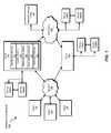
- FIG. 1is a block diagram of an exemplary network architecture 100 in which client systems 110 , 120 , and 130 and servers 140 and 145 may be coupled to a network 150 .
- Client systems 110 , 120 , and 130generally represent any type or form of computing device or system, such as exemplary computing system 210 in FIG. 2 .
- client system 110may include system 300 from FIG. 3 .
- servers 140 and 145generally represent computing devices or systems, such as application servers or database servers, configured to provide various database services and/or run certain software applications.
- Network 150generally represents any telecommunication or computer network including, for example, an intranet, a wide area network (WAN), a local area network (LAN), a personal area network (PAN), or the Internet.
- Server 140may include an identification module 101 , an update module 102 , a measurement module 103 , a determination module 104 , and/or a notification module 105 . These modules, as will be discussed in greater detail in FIG. 3 , may be programmed to measure compliance with a recovery point objective for an application.
- one or more storage devices 160 ( 1 )-(N)may be directly attached to server 140 .
- one or more storage devices 170 ( 1 )-(N)may be directly attached to server 145 .
- Storage devices 160 ( 1 )-(N) and storage devices 170 ( 1 )-(N)generally represent any type or form of storage device or medium capable of storing data and/or other computer-readable instructions.
- storage devices 160 ( 1 )-(N) and storage devices 170 ( 1 )-(N)may represent network-attached storage (NAS) devices configured to communicate with servers 140 and 145 using various protocols, such as NFS, SMB, or CIFS.
- NASnetwork-attached storage
- Servers 140 and 145may also be connected to a storage area network (SAN) fabric 180 .
- SAN fabric 180generally represents any type or form of computer network or architecture capable of facilitating communication between a plurality of storage devices.
- SAN fabric 180may facilitate communication between servers 140 and 145 and a plurality of storage devices 190 ( 1 )-(N) and/or an intelligent storage array 195 .
- SAN fabric 180may also facilitate, via network 150 and servers 140 and 145 , communication between client systems 110 , 120 , and 130 and storage devices 190 ( 1 )-(N) and/or intelligent storage array 195 in such a manner that devices 190 ( 1 )-(N) and array 195 appear as locally attached devices to client systems 110 , 120 , and 130 .
- storage devices 190 ( 1 )-(N) and intelligent storage array 195generally represent any type or form of storage device or medium capable of storing data and/or other computer-readable instructions.
- a communication interfacesuch as communication interface 222 in FIG. 2
- Client systems 110 , 120 , and 130may be able to access information on server 140 or 145 using, for example, a web browser or other client software.
- client softwaremay allow client systems 110 , 120 , and 130 to access data hosted by server 140 , server 145 , storage devices 160 ( 1 )-(N), storage devices 170 ( 1 )-(N), storage devices 190 ( 1 )-(N), or intelligent storage array 195 .
- FIG. 1depicts the use of a network (such as the Internet) for exchanging data, the embodiments described and/or illustrated herein are not limited to the Internet or any particular network-based environment.
- all or a portion of one or more of the exemplary embodiments disclosed hereinmay be encoded as a computer program and loaded onto and executed by server 140 , server 145 , storage devices 160 ( 1 )-(N), storage devices 170 ( 1 )-(N), storage devices 190 ( 1 )-(N), intelligent storage array 195 , or any combination thereof. All or a portion of one or more of the exemplary embodiments disclosed herein may also be encoded as a computer program, stored in server 140 , run by server 145 , and distributed to client systems 110 , 120 , and 130 over network 150 .
- network architecture 100may perform and/or be a means for performing, either alone or in combination with other elements, one or more of the identifying, updating, measuring, determining, providing, storing, changing, and/or invalidating steps disclosed herein.
- Network architecture 100may also be used to perform and/or be a means for performing other steps and features set forth in the instant disclosure.
- FIG. 2is a block diagram of an exemplary computing system 210 capable of implementing one or more of the embodiments described and/or illustrated herein.
- Computing system 210broadly represents any single or multi-processor computing device or system capable of executing computer-readable instructions. Examples of computing system 210 include, without limitation, workstations, laptops, client-side terminals, servers, distributed computing systems, handheld devices, or any other computing system or device. In its most basic configuration, computing system 210 may include at least one processor 214 and a system memory 216 .
- Processor 214generally represents any type or form of processing unit capable of processing data or interpreting and executing instructions.
- processor 214may receive instructions from a software application or module. These instructions may cause processor 214 to perform the functions of one or more of the exemplary embodiments described and/or illustrated herein.
- processor 214may perform and/or be a means for performing, either alone or in combination with other elements, one or more of the identifying, updating, measuring, determining, providing, storing, changing, and/or invalidating steps described herein.
- Processor 214may also perform and/or be a means for performing any other steps, methods, or processes described and/or illustrated herein.
- System memory 216generally represents any type or form of volatile or non-volatile storage device or medium capable of storing data and/or other computer-readable instructions. Examples of system memory 216 include, without limitation, random access memory (RAM), read only memory (ROM), flash memory, or any other suitable memory device. Although not required, in certain embodiments computing system 210 may include both a volatile memory unit (such as, for example, system memory 216 ) and a non-volatile storage device (such as, for example, primary storage device 232 , as described in detail below). One or more modules configured to measure compliance with a recovery point objective for an application may be loaded into system memory 216 . For example, identification module 101 , update module 102 , measurement module 103 , determination module 104 , and/or notification module 105 may be loaded into system memory 216 .
- RAMrandom access memory
- ROMread only memory
- flash memoryor any other suitable memory device.
- computing system 210may include both a volatile memory unit (such as, for example, system memory 216 ) and
- exemplary computing system 210may also include one or more components or elements in addition to processor 214 and system memory 216 .
- computing system 210may include a memory controller 218 , an Input/Output (I/O) controller 220 , and a communication interface 222 , each of which may be interconnected via a communication infrastructure 212 .
- Communication infrastructure 212generally represents any type or form of infrastructure capable of facilitating communication between one or more components of a computing device. Examples of communication infrastructure 212 include, without limitation, a communication bus (such as an ISA, PCI, PCIe, or similar bus) and a network.
- Memory controller 218generally represents any type or form of device capable of handling memory or data or controlling communication between one or more components of computing system 210 .
- memory controller 218may control communication between processor 214 , system memory 216 , and I/O controller 220 via communication infrastructure 212 .
- memory controllermay perform and/or be a means for performing, either alone or in combination with other elements, one or more of the steps or features described and/or illustrated herein, such as identifying, updating, measuring, determining, providing, storing, changing, and/or invalidating.
- I/O controller 220generally represents any type or form of module capable of coordinating and/or controlling the input and output functions of a computing device.
- I/O controller 220may control or facilitate transfer of data between one or more elements of computing system 210 , such as processor 214 , system memory 216 , communication interface 222 , display adapter 226 , input interface 230 , and storage interface 234 .
- I/O controller 220may be used, for example, to perform and/or be a means for performing, either alone or in combination with other elements, one or more of the identifying, updating, measuring, determining, providing, storing, changing, and/or invalidating steps described herein.
- I/O controller 220may also be used to perform and/or be a means for performing other steps and features set forth in the instant disclosure.
- Communication interface 222broadly represents any type or form of communication device or adapter capable of facilitating communication between exemplary computing system 210 and one or more additional devices.
- communication interface 222may facilitate communication between computing system 210 and a private or public network including additional computing systems.
- Examples of communication interface 222include, without limitation, a wired network interface (such as a network interface card), a wireless network interface (such as a wireless network interface card), a modem, and any other suitable interface.
- communication interface 222may provide a direct connection to a remote server via a direct link to a network, such as the Internet.
- Communication interface 222may also indirectly provide such a connection through, for example, a local area network (such as an Ethernet network), a personal area network, a telephone or cable network, a cellular telephone connection, a satellite data connection, or any other suitable connection.
- communication interface 222may also represent a host adapter configured to facilitate communication between computing system 210 and one or more additional network or storage devices via an external bus or communications channel.
- host adaptersinclude, without limitation, SCSI host adapters, USB host adapters, IEEE 294 host adapters, SATA and eSATA host adapters, ATA and PATA host adapters, Fibre Channel interface adapters, Ethernet adapters, or the like.
- Communication interface 222may also allow computing system 210 to engage in distributed or remote computing. For example, communication interface 222 may receive instructions from a remote device or send instructions to a remote device for execution.
- communication interface 222may perform and/or be a means for performing, either alone or in combination with other elements, one or more of the identifying, updating, measuring, determining, providing, storing, changing, and/or invalidating steps disclosed herein.
- Communication interface 222may also be used to perform and/or be a means for performing other steps and features set forth in the instant disclosure.
- computing system 210may also include at least one display device 224 coupled to communication infrastructure 212 via a display adapter 226 .
- Display device 224generally represents any type or form of device capable of visually displaying information forwarded by display adapter 226 .
- display adapter 226generally represents any type or form of device configured to forward graphics, text, and other data from communication infrastructure 212 (or from a frame buffer, as known in the art) for display on display device 224 .
- exemplary computing system 210may also include at least one input device 228 coupled to communication infrastructure 212 via an input interface 230 .
- Input device 228generally represents any type or form of input device capable of providing input, either computer or human generated, to exemplary computing system 210 .
- Examples of input device 228include, without limitation, a keyboard, a pointing device, a speech recognition device, or any other input device.
- input device 228may perform and/or be a means for performing, either alone or in combination with other elements, one or more of the identifying, updating, measuring, determining, providing, storing, changing, and/or invalidating steps disclosed herein.
- Input device 228may also be used to perform and/or be a means for performing other steps and features set forth in the instant disclosure.
- exemplary computing system 210may also include a primary storage device 232 and a backup storage device 233 coupled to communication infrastructure 212 via a storage interface 234 .
- Storage devices 232 and 233generally represent any type or form of storage device or medium capable of storing data and/or other computer-readable instructions.
- storage devices 232 and 233may be a magnetic disk drive (e.g., a so-called hard drive), a floppy disk drive, a magnetic tape drive, an optical disk drive, a flash drive, or the like.
- Storage interface 234generally represents any type or form of interface or device for transferring data between storage devices 232 and 233 and other components of computing system 210 .
- storage devices 232 and 233may be configured to read from and/or write to a removable storage unit configured to store computer software, data, or other computer-readable information.
- suitable removable storage unitsinclude, without limitation, a floppy disk, a magnetic tape, an optical disk, a flash memory device, or the like.
- Storage devices 232 and 233may also include other similar structures or devices for allowing computer software, data, or other computer-readable instructions to be loaded into computing system 210 .
- storage devices 232 and 233may be configured to read and write software, data, or other computer-readable information.
- Storage devices 232 and 233may also be a part of computing system 210 or may be a separate device accessed through other interface systems.
- storage devices 232 and 233may be used, for example, to perform and/or be a means for performing, either alone or in combination with other elements, one or more of the identifying, updating, measuring, determining, providing, storing, changing, and/or invalidating steps disclosed herein.
- Storage devices 232 and 233may also be used to perform and/or be a means for performing other steps and features set forth in the instant disclosure.
- computing system 210may be connected to many other devices or subsystems. Conversely, all of the components and devices illustrated in FIG. 2 need not be present to practice the embodiments described and/or illustrated herein. The devices and subsystems referenced above may also be interconnected in different ways from that shown in FIG. 2 .
- Computing system 210may also employ any number of software, firmware, and/or hardware configurations. For example, one or more of the exemplary embodiments disclosed herein may be encoded as a computer program (also referred to as computer software, software applications, computer-readable instructions, or computer control logic) on a computer-readable medium.
- the phrase “computer-readable medium”generally refers to any form of device, carrier, or medium capable of storing or carrying computer-readable instructions.
- Examples of computer-readable mediainclude, without limitation, transmission-type media, such as carrier waves, and physical media, such as magnetic-storage media (e.g., hard disk drives and floppy disks), optical-storage media (e.g., CD- or DVD-ROMs), electronic-storage media (e.g., solid-state drives and flash media), and other distribution systems.
- transmission-type mediasuch as carrier waves
- physical mediasuch as magnetic-storage media (e.g., hard disk drives and floppy disks), optical-storage media (e.g., CD- or DVD-ROMs), electronic-storage media (e.g., solid-state drives and flash media), and other distribution systems.
- the computer-readable medium containing the computer programmay be loaded into computing system 210 . All or a portion of the computer program stored on the computer-readable medium may then be stored in system memory 216 and/or various portions of storage devices 232 and 233 .
- a computer program loaded into computing system 210may cause processor 214 to perform and/or be a means for performing the functions of one or more of the exemplary embodiments described and/or illustrated herein. Additionally or alternatively, one or more of the exemplary embodiments described and/or illustrated herein may be implemented in firmware and/or hardware.
- computing system 210may be configured as an application specific integrated circuit (ASIC) adapted to implement one or more of the exemplary embodiments disclosed herein.
- ASICapplication specific integrated circuit
- FIG. 3is a block diagram of an exemplary system 300 for measuring compliance with a recovery point objective for an application.
- exemplary system 300may include, within system memory 216 , one or more modules 310 for performing one or more tasks.
- Modules 310may include identification module 101 , update module 102 , measurement module 103 , determination module 104 , and notification module 105 .
- Identification module 101may be programmed to identify a set of mount points on a primary site written to by the application and to identify a secondary site used for asynchronous replication of the primary site.
- Update module 102may be programmed to periodically update a time value on each mount point in the set of mount points on the primary site.
- Measurement module 103may be programmed to measure a replication lag by calculating a difference between the time value on the mount point and a replication of the time value on a corresponding mount point on the secondary site.
- Determination module 104may be programmed to determine the longest replication lag for any mount point in the set of mount points, and notification module 105 may be programmed to determine whether the longest replication lag exceeds the recovery point objective for the application and to provide a notice of a violation of the recovery point objective.
- one or more of modules 310 in FIG. 3may represent one or more software applications or programs that, when executed by a computing device, may cause the computing device to perform one or more tasks.
- one or more of modules 310may represent software modules stored and configured to run on one or more computing devices, such as the devices illustrated in FIG. 4 (e.g., primary site 404 , secondary site 406 , and/or computing device 402 ), computing system 210 in FIG. 2 , and/or portions of exemplary network architecture 100 in FIG. 1 .
- One or more of modules 310 in FIG. 3may also represent all or portions of one or more special-purpose computers configured to perform one or more tasks.
- exemplary system 300may include primary storage device 232 of FIG. 2 .
- update module 102may periodically update a time value on a mount point for primary storage device 232 .
- Exemplary system 300may include one or more processors, such as processor 214 of FIG. 2 .
- Processor 214may execute instructions forming part of one or more of modules 310 .
- Exemplary system 300may further include communication interface 222 of FIG. 2 .
- Communication interface 222may provide connectivity within exemplary system 300 or between exemplary system 300 and another system.
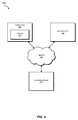
- FIG. 4is a block diagram of an exemplary system 400 for measuring compliance with a recovery point objective for an application.
- exemplary system 400may include a computing device 402 , a primary site 404 , and a secondary site 406 connected via network 150 .
- primary site 404may include one or more of modules 310 .
- Primary site 404may include an application with data asynchronously replicated to secondary site 406 .
- Primary site 404may include modules 310 to measure compliance with a recovery point objective for the application. For example, a system administrator may initiate a disaster recovery test for primary site 404 and secondary site 406 from computing device 402 .
- Identification module 101 on primary site 404may then identify a set of mount points on primary site 404 .
- Identification module 101may also identify secondary site 406 .
- Update module 102may update a time value on each mount point in the set of mount points on primary site 404 .
- Measurement module 103may then measure, for each mount point in the set of mount points, a replication lag by calculating the difference between the time value on the mount point and a replication of the time value on a corresponding mount point on secondary site 406 .
- At least part of one or more of modules 310may be located on computing device 402 and/or secondary site 406 .
- part of identification module 101may be located on computing device 402 (e.g., identification module 101 may read a configuration file located on computing device 402 listing all mount points on the primary site used by the application).
- Computing device 402generally represents any type or form of computing device capable of reading computer-executable instructions. Examples of computing device 402 include, without limitation, laptops, desktops, servers, cellular phones, personal digital assistants (PDAs), multimedia players, embedded systems, combinations of one or more of the same, exemplary computing system 210 in FIG. 2 , or any other suitable computing device.
- Examples of computing device 402include, without limitation, laptops, desktops, servers, cellular phones, personal digital assistants (PDAs), multimedia players, embedded systems, combinations of one or more of the same, exemplary computing system 210 in FIG. 2 , or any other suitable computing device.
- PDAspersonal digital assistants
- Primary site 404generally represents any type or form of computing system that is capable of hosting an application. Examples of primary site 404 include, without limitation, application servers and database servers configured to provide various database services and/or run certain software applications. Primary site 404 may also include, without limitation, laptops, desktops, cellular phones, personal digital assistants (PDAs), multimedia players, embedded systems, combinations of one or more of the same, exemplary computing system 210 in FIG. 2 , or any other suitable computing device.
- PDAspersonal digital assistants
- Secondary site 406generally represents any type or form of computing system that is capable of mirroring or hosting a replication of a computing system such as primary site 404 .
- secondary site 406may include a backup server configured for receiving asynchronous replication.
- Secondary site 406may also include, without limitation, laptops, desktops, cellular phones, personal digital assistants (PDAs), multimedia players, embedded systems, combinations of one or more of the same, exemplary computing system 210 in FIG. 2 , or any other suitable computing device.
- PDAspersonal digital assistants
- Network 150generally represents any medium or architecture capable of facilitating communication or data transfer. Examples of network 150 include, without limitation, an intranet, a Wide Area Network (“WAN”), a Local Area Network (“LAN”), a Personal Area Network (“PAN”), the Internet, Power Line Communications (“PLC”), a cellular network (e.g., a GSM Network), all or a portion of exemplary network architecture 100 in FIG. 1 , or the like. Network 150 may facilitate communication or data transfer using wireless or wired connections. In one embodiment, network 150 may facilitate communication between computing device 402 and primary site 404 . In some embodiments, network 150 may facilitate communication between primary site 404 and secondary site 406 .
- WANWide Area Network
- LANLocal Area Network
- PANPersonal Area Network
- PLCPower Line Communications
- GSM NetworkGlobal System for Mobile communications
- FIG. 5is a block diagram of an exemplary system 500 for measuring compliance with a recovery point objective for an application.
- exemplary system 500may include primary site 404 and secondary site 406 , which may be connected by network 150 .
- Primary site 404may include system memory 216 , primary storage device 232 , display device 224 , communication interface 222 , and processor 214 of FIG. 2 .
- Primary storage device 232may also include a set of mount points 530 .
- Set of mount points 530may include a mount point 532 and a mount point 536 . While set of mount points 530 shows two mount points, a set of mount points may include one mount point or any other number of mount points.
- Mount point 532may include a file 533 , which may include a time value 534 and a session ID 535 .
- mount point 536may include a file 537 , which may include a time value 538 and a session ID 539 .
- Display device 224may include a notice of violation 560 .
- mount pointsmay include a time value but no session ID.
- a “mount point”may refer to any directory, logical drive, and/or any other mapping mechanism that links a storage device or a partition of a storage device to a file system.
- a “mount point”may a include MICROSOFT WINDOWS drive (e.g., a C: drive), an NFTS volume mount point, or a UNIX, LINUX, or other UNIX-like mount point.
- the mount pointmay also reside on a virtual disk in virtual machine embodiments.
- secondary site 406may include corresponding mount point 542 and corresponding mount point 546 .
- Corresponding mount point 542may be a mount point associated with data copied from mount point 532
- corresponding mount point 546may be a mount point associated with data copied from mount point 536 .
- Corresponding mount point 542may include time value replication 544 and session ID replication 545
- corresponding mount point 546may include time value replication 548 and session ID replication 549 .
- System memory 216may include identification module 101 , update module 102 , measurement module 103 , determination module 104 , and notification module 105 .
- System memory 216may also include a replication lag 524 , a replication lag 528 , a recovery point objective 550 , and an application 551 .
- Application 551may include any set of one or more computer-executable instructions.
- Application 551may include a word processor, a browser, a system tool, a game, and/or any other software application.
- Measurement module 103may measure replication lag 524 by calculating a difference between time value replication 544 and time value 534 , and session ID 535 may be compared with session ID replication 545 to determine whether replication lag 524 is valid. Similarly, measurement module 103 may measure replication lag 528 by calculating a difference between time value replication 548 and time value 538 , and session ID 539 may be compared with session ID replication 549 to determine whether replication lag 528 is valid. In some embodiments, notification module 105 may determine that replication lag 524 and/or replication lag 528 exceeds recovery point objective 550 and may provide a notice of violation 560 on display device 224 .
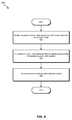
- FIGS. 6-9are flow diagrams of exemplary computer-implemented methods for measuring compliance with a recovery point objective for an application.
- the steps shown in FIGS. 6-9may be performed by any suitable computer-executable code and/or computing system. In some embodiments, the steps shown in FIG. 6-9 may be performed by one or more of the components of system 100 in FIG. 1 and/or system 200 in FIG. 2 .
- identification module 101may identify set of mount points 530 , which may be written to by application 551 .
- Identification module 101may identify set of mount points 530 in a variety of ways. For example, identification module 101 may identify set of mount points 530 by retrieving set of mount points 530 from a configuration file. Alternatively, identification module 101 may identify set of mount points 530 by monitoring and/or analyzing application 551 to determine which mount points are written to by application 551 .
- identification module 101may identify secondary site 406 , which may be used for asynchronous replication (e.g., backup) of primary site 404 .
- identification module 101may identify secondary site 406 by reading a configuration file or by receiving the identity of the secondary site from a volume replicator.
- update module 102may periodically update a time value on each mount point in set of mount points 530 on primary site 404 .
- Update module 102may update a time value in any number of ways. For instance, update module 102 may update a time value on a mount point by updating the time value in a file stored on the mount point.
- /mnt1may represent mount point 532 .
- update module 102may periodically update time value 534 , which may be stored in a file at /mnt1/SQN.txt.
- Update module 102may also update a time value on a mount point by updating the time value in metadata of a file system of the mount point. For example, update module 102 may write to the metadata through an unpublished interface (e.g., an Input/Output Control (“IOCTL”)). Additionally or alternatively, update module 102 may update a time value on a mount point by extending a file system driver to periodically update the time value.
- IOCTLInput/Output Control
- update module 102may run under the same operating system image as application 551 so that update module 102 may have the same view of primary storage device 232 as application 551 . Furthermore, update module 102 may function at the same level of storage abstraction that is visible to application 551 . This may help to ensure that mount point time values accurately reflect the latest time of possible data changes corresponding to application 551 .
- a time valuemay include any type of value which may be compared with a value of the same type to ascertain the difference in time between the values.
- the time valuemay include a sequentially incremented number.
- update module 102may update the time value every second. The sequentially incremented number may begin at 0 and increment by 1 at each update.
- An advantage of using sequentially incremented numbersis that time-sync may not be required and the sequentially incremented numbers may be substantially independent of skews.
- the time valuemay include a time stamp.
- update module 102may periodically retrieve the current time from a clock device in computing system 500 of primary site 404 and may update time value 534 and/or 538 with the current time.
- measurement module 103may, for each mount point in set of mount points 530 , measure a replication lag by calculating a difference between the time value on the mount point and a replication of the time value on a corresponding mount point on secondary site 406 .
- identification module 101may obtain replicated time values from mount points on a secondary site by taking a point-in-time snapshot of the replicated storage at a time when a disaster-recovery test is started.
- the replication lag for a mount pointgenerally indicates the amount of time separating the latest state of the primary site and latest state of replication at the secondary site.
- application 551 on primary site 404may write to two mount points, mount point 532 and mount point 536 , which may be represented by /mnt1 and /mnt2, respectively.
- Update module 102may periodically update the time value for each mount point at /mnt1/SQN.txt and /mnt2/SQN.txt.
- the time value stored on each mount pointmay include a sequentially incremented number representing a number of seconds.
- An administratormay simulate a disaster to the primary site through a disaster recovery test.
- Measurement module 103may then read 100 and 125 as the respective time values in the files on the mount points of primary site 404 as of the time of the simulated disaster. Measurement module 103 may further read 75 and 90 as the respective time values in the replicated files on the corresponding mount points of secondary site 406 . Measurement module 103 may then calculate the difference of each pair of time values to determine the replication lag in seconds-25 seconds and 35 seconds, respectively. In other words, in this example, replication lag 524 may be 25 seconds and replication lag 528 may be 35 seconds.
- An advantage of the method disclosed in FIG. 6is that it may scale with little or no changes when an application mount point is configured on different storage arrays with different volume managers.
- an applicationmay have a mount point “mnt1” with LVM on a CLARION array and mount point “mnt2” with VxVM on a HITACHI array.
- the longest replication lag of the applicationmay be computed as the maximum of the replication lags of /mnt1 and /mnt2.
- FIG. 7illustrates a method for detecting and providing a notice for a violation of a recovery point objective.
- the method of FIG. 7may incorporate or operate in conjunction with the method of FIG. 6 .
- determination module 104may determine a longest replication lag for any mount point in set of mount points 530 .
- Determination module 104may determine the longest replication lag by comparing each replication lag (e.g., with a MAX( ) function).
- measurement module 103may have measured the replication lag for mount points /mnt1 and /mnt2 as 25 seconds and 35 seconds, respectively. Determination module 104 may determine that 35 seconds is the longest replication lag.
- notification module 105may determine that the longest replication lag exceeds the recovery point objective for an application, such as application 551 .
- the longest replication lagmay be 35 seconds. If recovery point objective 550 is 30 seconds, then notification module 105 may determine that the longest replication lag exceeds recovery point objective 550 .
- notification module 105may provide a notice of a violation of recovery point objective 550 .
- Notification module 105may provide the notice in a variety of contexts. In one example, notification module 105 may provide the notice by displaying the notice on a display device, such as display device 224 , a display device connected to computing device 402 of FIG. 4 , and/or a display device included in primary site 404 . Additionally or alternatively, notification module 105 may record the notice of the violation in a log file, transmit the notice of the violation by e-mail or another electronic message system, and/or print the notice of the violation from a printing device.
- FIG. 8illustrates a method for detecting and providing a notice for a violation of a recovery point objective in the context of multiple recovery point objectives.
- identification module 101may identify a recovery point objective for each mount point in a set of mount points. Identification module 101 may identify the recovery point objective for each mount point in a variety of ways. For example, identification module 101 may identify the recovery point objective for each mount point by retrieving the recovery point objectives from a configuration file. Alternatively, identification module 101 may identify certain mount points (such as any synchronously replicated mount points) as having no recovery point objective and assign those mount points with a value of 0.
- notification module 105may determine that, for at least one mount point, the replication lag exceeds the separate recovery point objective.
- measurement module 103may have measured the replication lag for mount points /mnt1 and /mnt2 as 25 seconds and 35 seconds, respectively.
- Identification module 101may have identified the recovery point objectives for the mount points as 20 seconds and none, respectively. Accordingly, notification module 105 may determine that the replication lag of /mnt1 exceeds its recovery point objective.
- notification module 105may provide a notice of a violation of the separate recovery point objective.
- Notification module 105may provide the notice in any suitable manner. For example, notification module 105 may provide the notice by any of the methods provided as examples in the description of step 706 of FIG. 7 .
- FIG. 9illustrates a method for determining that a measurement of a replication lag is invalid.
- update module 102may store a session identification number on each mount point in the set of mount points.
- update module 102may store the session identification number in the same location as the time value for the mount point, as shown in FIG. 5 .
- update module 102may determine that a periodic update of a time value has failed. For example, update module 102 may determine that a periodic update of a time value has failed if it receives an error when attempting to update the time value (e.g., the file containing the time value may be temporarily unavailable for writing due to a system fault). Generally, update module 102 may determine that a periodic update of the time value has failed whenever it fails to update the time value.
- update module 102may change the session identification number for the mount point. For example, update module 102 may increment the session identification number. In some embodiments, update module 102 may also reset the time value to zero (e.g., if the time value is a sequentially incremented number) when changing the session identification number. For example, each mount point may start with a session identification number of 1. Update module 102 may store the time value and session number for mount point /mnt1 in /mnt1/SQN.txt. If the latest time value for /mnt1 is 75, /mnt1/SQN.txt may contain 75:1. If update module 102 fails to update the time value to 76, at the next opportunity update module 102 may update /mnt1/SQN.txt with the values 0:2 instead of 76:1.
- measurement module 103may determine that the session identification number for the mount point does not match a replication of the session identification number on a corresponding mount point on the secondary site. For example, measurement module 103 may read 75:1 from /mnt1/SQN.txt on the secondary site and 4:2 from /mnt1/SQN.txt on the primary site. Measurement module 103 may determine that the session identification numbers do not match.
- measurement module 103may invalidate a measurement of the replication lag for the mount point. For instance, using the example above, measurement module 103 may calculate a replication lag of ⁇ 71 seconds but may invalidate the calculation based on the different session identification numbers. In some embodiments, measurement module 103 may invalidate the measurement of the replication lag by providing a notice that the measurement of the replication lag of the mount point was invalid.
- embodiments of the instant disclosuremay be platform agnostic.
- some embodimentsmay scale well to virtual machines because they may calculate replication lags of a virtual disk, which may be considered as mount points seen by an application running inside a guest operating system.
- the virtual diskmay reside on any storage, and in some embodiments replication lag may be calculated without knowledge of an underlying storage stack which hosts the virtual disk file.
- Such embodimentsmay operate at a virtual disk level and avoid the non-trivial task of mapping a virtual disk file to an underlying storage unit.
- one or more of the software modules disclosed hereinmay be implemented in a cloud computing environment.
- Cloud computing environmentsmay provide various services and applications via the internet. These cloud-based services (e.g., software as a service, platform as a service, infrastructure as a service, etc.) may be accessible through a web browser or other remote interface.
- Various functions described hereinmay be provided through a remote desktop environment or any other cloud-based computing environment.
- secondary site 406may be located in a cloud, and one or more of module 310 may operate in a cloud computing environment.
- One or more of the software modules described hereinmay transform data, physical devices, and/or representations of physical devices from one form to another.
- one or more of modules 310may transform primary storage device 232 by modifying time values, session IDs, and/or other data on primary storage device 232 .
Landscapes
- Engineering & Computer Science (AREA)
- Theoretical Computer Science (AREA)
- Physics & Mathematics (AREA)
- General Engineering & Computer Science (AREA)
- General Physics & Mathematics (AREA)
- Quality & Reliability (AREA)
- Computing Systems (AREA)
- Computer Hardware Design (AREA)
- Mathematical Physics (AREA)
- Data Mining & Analysis (AREA)
- Databases & Information Systems (AREA)
- Information Retrieval, Db Structures And Fs Structures Therefor (AREA)
Abstract
Description
Claims (20)
Priority Applications (1)
| Application Number | Priority Date | Filing Date | Title |
|---|---|---|---|
| US12/493,462US9110918B1 (en) | 2009-06-29 | 2009-06-29 | Systems and methods for measuring compliance with a recovery point objective for an application |
Applications Claiming Priority (1)
| Application Number | Priority Date | Filing Date | Title |
|---|---|---|---|
| US12/493,462US9110918B1 (en) | 2009-06-29 | 2009-06-29 | Systems and methods for measuring compliance with a recovery point objective for an application |
Publications (1)
| Publication Number | Publication Date |
|---|---|
| US9110918B1true US9110918B1 (en) | 2015-08-18 |
Family
ID=53786021
Family Applications (1)
| Application Number | Title | Priority Date | Filing Date |
|---|---|---|---|
| US12/493,462Active2033-06-18US9110918B1 (en) | 2009-06-29 | 2009-06-29 | Systems and methods for measuring compliance with a recovery point objective for an application |
Country Status (1)
| Country | Link |
|---|---|
| US (1) | US9110918B1 (en) |
Cited By (72)
| Publication number | Priority date | Publication date | Assignee | Title |
|---|---|---|---|---|
| US20130166505A1 (en)* | 2011-12-22 | 2013-06-27 | Noam Peretz | Monitoring replication lag between geographically dispersed sites |
| WO2017132437A1 (en)* | 2016-01-29 | 2017-08-03 | Veritas Technologies Llc | Adjusting replicaiton operations in a distributed environment |
| US9983947B2 (en) | 2016-07-19 | 2018-05-29 | International Business Machines Corporation | Snapshots at real time intervals on asynchronous data replication system |
| US11392720B2 (en) | 2016-06-10 | 2022-07-19 | OneTrust, LLC | Data processing systems for verification of consent and notice processing and related methods |
| US11403377B2 (en) | 2016-06-10 | 2022-08-02 | OneTrust, LLC | Privacy management systems and methods |
| US11409908B2 (en) | 2016-06-10 | 2022-08-09 | OneTrust, LLC | Data processing systems and methods for populating and maintaining a centralized database of personal data |
| US11410106B2 (en) | 2016-06-10 | 2022-08-09 | OneTrust, LLC | Privacy management systems and methods |
| US11416589B2 (en) | 2016-06-10 | 2022-08-16 | OneTrust, LLC | Data processing and scanning systems for assessing vendor risk |
| US11416109B2 (en) | 2016-06-10 | 2022-08-16 | OneTrust, LLC | Automated data processing systems and methods for automatically processing data subject access requests using a chatbot |
| US11416636B2 (en) | 2016-06-10 | 2022-08-16 | OneTrust, LLC | Data processing consent management systems and related methods |
| US11418492B2 (en) | 2016-06-10 | 2022-08-16 | OneTrust, LLC | Data processing systems and methods for using a data model to select a target data asset in a data migration |
| US11416576B2 (en) | 2016-06-10 | 2022-08-16 | OneTrust, LLC | Data processing consent capture systems and related methods |
| US11418516B2 (en) | 2016-06-10 | 2022-08-16 | OneTrust, LLC | Consent conversion optimization systems and related methods |
| US11416798B2 (en) | 2016-06-10 | 2022-08-16 | OneTrust, LLC | Data processing systems and methods for providing training in a vendor procurement process |
| US11416590B2 (en) | 2016-06-10 | 2022-08-16 | OneTrust, LLC | Data processing and scanning systems for assessing vendor risk |
| US11416634B2 (en) | 2016-06-10 | 2022-08-16 | OneTrust, LLC | Consent receipt management systems and related methods |
| US11438386B2 (en) | 2016-06-10 | 2022-09-06 | OneTrust, LLC | Data processing systems for data-transfer risk identification, cross-border visualization generation, and related methods |
| US11436373B2 (en) | 2020-09-15 | 2022-09-06 | OneTrust, LLC | Data processing systems and methods for detecting tools for the automatic blocking of consent requests |
| US11442906B2 (en) | 2021-02-04 | 2022-09-13 | OneTrust, LLC | Managing custom attributes for domain objects defined within microservices |
| US11444976B2 (en) | 2020-07-28 | 2022-09-13 | OneTrust, LLC | Systems and methods for automatically blocking the use of tracking tools |
| US11449633B2 (en) | 2016-06-10 | 2022-09-20 | OneTrust, LLC | Data processing systems and methods for automatic discovery and assessment of mobile software development kits |
| US11461500B2 (en) | 2016-06-10 | 2022-10-04 | OneTrust, LLC | Data processing systems for cookie compliance testing with website scanning and related methods |
| US11461722B2 (en) | 2016-06-10 | 2022-10-04 | OneTrust, LLC | Questionnaire response automation for compliance management |
| US11468196B2 (en) | 2016-06-10 | 2022-10-11 | OneTrust, LLC | Data processing systems for validating authorization for personal data collection, storage, and processing |
| US11468386B2 (en) | 2016-06-10 | 2022-10-11 | OneTrust, LLC | Data processing systems and methods for bundled privacy policies |
| US11475136B2 (en) | 2016-06-10 | 2022-10-18 | OneTrust, LLC | Data processing systems for data transfer risk identification and related methods |
| US11475165B2 (en) | 2020-08-06 | 2022-10-18 | OneTrust, LLC | Data processing systems and methods for automatically redacting unstructured data from a data subject access request |
| US11481710B2 (en) | 2016-06-10 | 2022-10-25 | OneTrust, LLC | Privacy management systems and methods |
| US11494515B2 (en) | 2021-02-08 | 2022-11-08 | OneTrust, LLC | Data processing systems and methods for anonymizing data samples in classification analysis |
| US11520928B2 (en) | 2016-06-10 | 2022-12-06 | OneTrust, LLC | Data processing systems for generating personal data receipts and related methods |
| US11526624B2 (en) | 2020-09-21 | 2022-12-13 | OneTrust, LLC | Data processing systems and methods for automatically detecting target data transfers and target data processing |
| US11533315B2 (en) | 2021-03-08 | 2022-12-20 | OneTrust, LLC | Data transfer discovery and analysis systems and related methods |
| US11544667B2 (en) | 2016-06-10 | 2023-01-03 | OneTrust, LLC | Data processing systems for generating and populating a data inventory |
| US11544405B2 (en) | 2016-06-10 | 2023-01-03 | OneTrust, LLC | Data processing systems for verification of consent and notice processing and related methods |
| US11544409B2 (en) | 2018-09-07 | 2023-01-03 | OneTrust, LLC | Data processing systems and methods for automatically protecting sensitive data within privacy management systems |
| US11546661B2 (en) | 2021-02-18 | 2023-01-03 | OneTrust, LLC | Selective redaction of media content |
| US11550897B2 (en) | 2016-06-10 | 2023-01-10 | OneTrust, LLC | Data processing and scanning systems for assessing vendor risk |
| US11558429B2 (en) | 2016-06-10 | 2023-01-17 | OneTrust, LLC | Data processing and scanning systems for generating and populating a data inventory |
| US11562078B2 (en) | 2021-04-16 | 2023-01-24 | OneTrust, LLC | Assessing and managing computational risk involved with integrating third party computing functionality within a computing system |
| US11562097B2 (en) | 2016-06-10 | 2023-01-24 | OneTrust, LLC | Data processing systems for central consent repository and related methods |
| US11586762B2 (en) | 2016-06-10 | 2023-02-21 | OneTrust, LLC | Data processing systems and methods for auditing data request compliance |
| US11586700B2 (en) | 2016-06-10 | 2023-02-21 | OneTrust, LLC | Data processing systems and methods for automatically blocking the use of tracking tools |
| US11593523B2 (en) | 2018-09-07 | 2023-02-28 | OneTrust, LLC | Data processing systems for orphaned data identification and deletion and related methods |
| US11601464B2 (en) | 2021-02-10 | 2023-03-07 | OneTrust, LLC | Systems and methods for mitigating risks of third-party computing system functionality integration into a first-party computing system |
| US11609939B2 (en) | 2016-06-10 | 2023-03-21 | OneTrust, LLC | Data processing systems and methods for automatically detecting and documenting privacy-related aspects of computer software |
| US11615192B2 (en) | 2020-11-06 | 2023-03-28 | OneTrust, LLC | Systems and methods for identifying data processing activities based on data discovery results |
| US11620142B1 (en) | 2022-06-03 | 2023-04-04 | OneTrust, LLC | Generating and customizing user interfaces for demonstrating functions of interactive user environments |
| US11625502B2 (en) | 2016-06-10 | 2023-04-11 | OneTrust, LLC | Data processing systems for identifying and modifying processes that are subject to data subject access requests |
| US11636171B2 (en) | 2016-06-10 | 2023-04-25 | OneTrust, LLC | Data processing user interface monitoring systems and related methods |
| US11645418B2 (en) | 2016-06-10 | 2023-05-09 | OneTrust, LLC | Data processing systems for data testing to confirm data deletion and related methods |
| US11651402B2 (en) | 2016-04-01 | 2023-05-16 | OneTrust, LLC | Data processing systems and communication systems and methods for the efficient generation of risk assessments |
| US11651104B2 (en) | 2016-06-10 | 2023-05-16 | OneTrust, LLC | Consent receipt management systems and related methods |
| US11651106B2 (en) | 2016-06-10 | 2023-05-16 | OneTrust, LLC | Data processing systems for fulfilling data subject access requests and related methods |
| US11663359B2 (en) | 2017-06-16 | 2023-05-30 | OneTrust, LLC | Data processing systems for identifying whether cookies contain personally identifying information |
| US11675929B2 (en) | 2016-06-10 | 2023-06-13 | OneTrust, LLC | Data processing consent sharing systems and related methods |
| US11687528B2 (en) | 2021-01-25 | 2023-06-27 | OneTrust, LLC | Systems and methods for discovery, classification, and indexing of data in a native computing system |
| US11727141B2 (en) | 2016-06-10 | 2023-08-15 | OneTrust, LLC | Data processing systems and methods for synching privacy-related user consent across multiple computing devices |
| US11775348B2 (en) | 2021-02-17 | 2023-10-03 | OneTrust, LLC | Managing custom workflows for domain objects defined within microservices |
| US11797528B2 (en) | 2020-07-08 | 2023-10-24 | OneTrust, LLC | Systems and methods for targeted data discovery |
| US11921894B2 (en) | 2016-06-10 | 2024-03-05 | OneTrust, LLC | Data processing systems for generating and populating a data inventory for processing data access requests |
| US12045266B2 (en) | 2016-06-10 | 2024-07-23 | OneTrust, LLC | Data processing systems for generating and populating a data inventory |
| US12052289B2 (en) | 2016-06-10 | 2024-07-30 | OneTrust, LLC | Data processing systems for data-transfer risk identification, cross-border visualization generation, and related methods |
| US12086748B2 (en) | 2016-06-10 | 2024-09-10 | OneTrust, LLC | Data processing systems for assessing readiness for responding to privacy-related incidents |
| US12118121B2 (en) | 2016-06-10 | 2024-10-15 | OneTrust, LLC | Data subject access request processing systems and related methods |
| US12136055B2 (en) | 2016-06-10 | 2024-11-05 | OneTrust, LLC | Data processing systems for identifying, assessing, and remediating data processing risks using data modeling techniques |
| US12147578B2 (en) | 2016-06-10 | 2024-11-19 | OneTrust, LLC | Consent receipt management systems and related methods |
| US12153704B2 (en) | 2021-08-05 | 2024-11-26 | OneTrust, LLC | Computing platform for facilitating data exchange among computing environments |
| US12164667B2 (en) | 2016-06-10 | 2024-12-10 | OneTrust, LLC | Application privacy scanning systems and related methods |
| US12190330B2 (en) | 2016-06-10 | 2025-01-07 | OneTrust, LLC | Data processing systems for identity validation for consumer rights requests and related methods |
| US12265896B2 (en) | 2020-10-05 | 2025-04-01 | OneTrust, LLC | Systems and methods for detecting prejudice bias in machine-learning models |
| US12299065B2 (en) | 2016-06-10 | 2025-05-13 | OneTrust, LLC | Data processing systems and methods for dynamically determining data processing consent configurations |
| US12381915B2 (en) | 2016-06-10 | 2025-08-05 | OneTrust, LLC | Data processing systems and methods for performing assessments and monitoring of new versions of computer code for compliance |
Citations (13)
| Publication number | Priority date | Publication date | Assignee | Title |
|---|---|---|---|---|
| US5657440A (en)* | 1994-03-21 | 1997-08-12 | International Business Machines Corporation | Asynchronous remote data copying using subsystem to subsystem communication |
| US6389016B1 (en)* | 1998-10-14 | 2002-05-14 | Nortel Networks Limited | Data communication system and method for transporting data |
| US20020095479A1 (en)* | 2001-01-18 | 2002-07-18 | Schmidt Brian Keith | Method and apparatus for virtual namespaces for active computing environments |
| US20030110190A1 (en)* | 2001-12-10 | 2003-06-12 | Hitachi, Ltd. | Method and system for file space management |
| US20060129562A1 (en)* | 2004-10-04 | 2006-06-15 | Chandrasekhar Pulamarasetti | System and method for management of recovery point objectives of business continuity/disaster recovery IT solutions |
| US7191225B1 (en)* | 2002-11-27 | 2007-03-13 | Veritas Operating Corporation | Mechanism to provide direct multi-node file system access to files on a single-node storage stack |
| US20090138471A1 (en)* | 2006-11-24 | 2009-05-28 | Hangzhou H3C Technologies Co., Ltd. | Method and apparatus for identifying data content |
| US20090157768A1 (en)* | 2007-12-18 | 2009-06-18 | Naoko Ichikawa | Computer system and data loss prevention method |
| US20090183027A1 (en)* | 2008-01-11 | 2009-07-16 | International Business Machines Corporation | Checkpointing and restoring user space data structures used by an application |
| US20090198949A1 (en)* | 2008-02-06 | 2009-08-06 | Doug Kuligowski | Hypervolume data storage object and method of data storage |
| US7702871B1 (en)* | 2007-08-31 | 2010-04-20 | Emc Corporation | Write pacing |
| US7756831B1 (en)* | 2006-09-28 | 2010-07-13 | Emc Corporation | Cooperative locking between multiple independent owners of data space |
| US20100306500A1 (en)* | 2009-06-02 | 2010-12-02 | Hitachi, Ltd. | Method and apparatus for managing thin provisioning volume by using file storage system |
- 2009
- 2009-06-29USUS12/493,462patent/US9110918B1/enactiveActive
Patent Citations (13)
| Publication number | Priority date | Publication date | Assignee | Title |
|---|---|---|---|---|
| US5657440A (en)* | 1994-03-21 | 1997-08-12 | International Business Machines Corporation | Asynchronous remote data copying using subsystem to subsystem communication |
| US6389016B1 (en)* | 1998-10-14 | 2002-05-14 | Nortel Networks Limited | Data communication system and method for transporting data |
| US20020095479A1 (en)* | 2001-01-18 | 2002-07-18 | Schmidt Brian Keith | Method and apparatus for virtual namespaces for active computing environments |
| US20030110190A1 (en)* | 2001-12-10 | 2003-06-12 | Hitachi, Ltd. | Method and system for file space management |
| US7191225B1 (en)* | 2002-11-27 | 2007-03-13 | Veritas Operating Corporation | Mechanism to provide direct multi-node file system access to files on a single-node storage stack |
| US20060129562A1 (en)* | 2004-10-04 | 2006-06-15 | Chandrasekhar Pulamarasetti | System and method for management of recovery point objectives of business continuity/disaster recovery IT solutions |
| US7756831B1 (en)* | 2006-09-28 | 2010-07-13 | Emc Corporation | Cooperative locking between multiple independent owners of data space |
| US20090138471A1 (en)* | 2006-11-24 | 2009-05-28 | Hangzhou H3C Technologies Co., Ltd. | Method and apparatus for identifying data content |
| US7702871B1 (en)* | 2007-08-31 | 2010-04-20 | Emc Corporation | Write pacing |
| US20090157768A1 (en)* | 2007-12-18 | 2009-06-18 | Naoko Ichikawa | Computer system and data loss prevention method |
| US20090183027A1 (en)* | 2008-01-11 | 2009-07-16 | International Business Machines Corporation | Checkpointing and restoring user space data structures used by an application |
| US20090198949A1 (en)* | 2008-02-06 | 2009-08-06 | Doug Kuligowski | Hypervolume data storage object and method of data storage |
| US20100306500A1 (en)* | 2009-06-02 | 2010-12-02 | Hitachi, Ltd. | Method and apparatus for managing thin provisioning volume by using file storage system |
Cited By (93)
| Publication number | Priority date | Publication date | Assignee | Title |
|---|---|---|---|---|
| US20130166505A1 (en)* | 2011-12-22 | 2013-06-27 | Noam Peretz | Monitoring replication lag between geographically dispersed sites |
| WO2017132437A1 (en)* | 2016-01-29 | 2017-08-03 | Veritas Technologies Llc | Adjusting replicaiton operations in a distributed environment |
| US10540238B2 (en) | 2016-01-29 | 2020-01-21 | Veritas Technologies Llc | Adjusting replication operations in a distributed environment |
| US12288233B2 (en) | 2016-04-01 | 2025-04-29 | OneTrust, LLC | Data processing systems and methods for integrating privacy information management systems with data loss prevention tools or other tools for privacy design |
| US11651402B2 (en) | 2016-04-01 | 2023-05-16 | OneTrust, LLC | Data processing systems and communication systems and methods for the efficient generation of risk assessments |
| US11586700B2 (en) | 2016-06-10 | 2023-02-21 | OneTrust, LLC | Data processing systems and methods for automatically blocking the use of tracking tools |
| US11921894B2 (en) | 2016-06-10 | 2024-03-05 | OneTrust, LLC | Data processing systems for generating and populating a data inventory for processing data access requests |
| US11416589B2 (en) | 2016-06-10 | 2022-08-16 | OneTrust, LLC | Data processing and scanning systems for assessing vendor risk |
| US11416109B2 (en) | 2016-06-10 | 2022-08-16 | OneTrust, LLC | Automated data processing systems and methods for automatically processing data subject access requests using a chatbot |
| US11416636B2 (en) | 2016-06-10 | 2022-08-16 | OneTrust, LLC | Data processing consent management systems and related methods |
| US11418492B2 (en) | 2016-06-10 | 2022-08-16 | OneTrust, LLC | Data processing systems and methods for using a data model to select a target data asset in a data migration |
| US11416576B2 (en) | 2016-06-10 | 2022-08-16 | OneTrust, LLC | Data processing consent capture systems and related methods |
| US11418516B2 (en) | 2016-06-10 | 2022-08-16 | OneTrust, LLC | Consent conversion optimization systems and related methods |
| US11416798B2 (en) | 2016-06-10 | 2022-08-16 | OneTrust, LLC | Data processing systems and methods for providing training in a vendor procurement process |
| US11416590B2 (en) | 2016-06-10 | 2022-08-16 | OneTrust, LLC | Data processing and scanning systems for assessing vendor risk |
| US11416634B2 (en) | 2016-06-10 | 2022-08-16 | OneTrust, LLC | Consent receipt management systems and related methods |
| US11438386B2 (en) | 2016-06-10 | 2022-09-06 | OneTrust, LLC | Data processing systems for data-transfer risk identification, cross-border visualization generation, and related methods |
| US11449633B2 (en) | 2016-06-10 | 2022-09-20 | OneTrust, LLC | Data processing systems and methods for automatic discovery and assessment of mobile software development kits |
| US11461500B2 (en) | 2016-06-10 | 2022-10-04 | OneTrust, LLC | Data processing systems for cookie compliance testing with website scanning and related methods |
| US12412140B2 (en) | 2016-06-10 | 2025-09-09 | OneTrust, LLC | Data processing systems and methods for bundled privacy policies |
| US12381915B2 (en) | 2016-06-10 | 2025-08-05 | OneTrust, LLC | Data processing systems and methods for performing assessments and monitoring of new versions of computer code for compliance |
| US11461722B2 (en) | 2016-06-10 | 2022-10-04 | OneTrust, LLC | Questionnaire response automation for compliance management |
| US11468196B2 (en) | 2016-06-10 | 2022-10-11 | OneTrust, LLC | Data processing systems for validating authorization for personal data collection, storage, and processing |
| US11468386B2 (en) | 2016-06-10 | 2022-10-11 | OneTrust, LLC | Data processing systems and methods for bundled privacy policies |
| US11475136B2 (en) | 2016-06-10 | 2022-10-18 | OneTrust, LLC | Data processing systems for data transfer risk identification and related methods |
| US12299065B2 (en) | 2016-06-10 | 2025-05-13 | OneTrust, LLC | Data processing systems and methods for dynamically determining data processing consent configurations |
| US11392720B2 (en) | 2016-06-10 | 2022-07-19 | OneTrust, LLC | Data processing systems for verification of consent and notice processing and related methods |
| US11481710B2 (en) | 2016-06-10 | 2022-10-25 | OneTrust, LLC | Privacy management systems and methods |
| US11488085B2 (en) | 2016-06-10 | 2022-11-01 | OneTrust, LLC | Questionnaire response automation for compliance management |
| US11609939B2 (en) | 2016-06-10 | 2023-03-21 | OneTrust, LLC | Data processing systems and methods for automatically detecting and documenting privacy-related aspects of computer software |
| US12204564B2 (en) | 2016-06-10 | 2025-01-21 | OneTrust, LLC | Data processing systems and methods for automatically detecting and documenting privacy-related aspects of computer software |
| US12190330B2 (en) | 2016-06-10 | 2025-01-07 | OneTrust, LLC | Data processing systems for identity validation for consumer rights requests and related methods |
| US11520928B2 (en) | 2016-06-10 | 2022-12-06 | OneTrust, LLC | Data processing systems for generating personal data receipts and related methods |
| US12164667B2 (en) | 2016-06-10 | 2024-12-10 | OneTrust, LLC | Application privacy scanning systems and related methods |
| US12158975B2 (en) | 2016-06-10 | 2024-12-03 | OneTrust, LLC | Data processing consent sharing systems and related methods |
| US11544667B2 (en) | 2016-06-10 | 2023-01-03 | OneTrust, LLC | Data processing systems for generating and populating a data inventory |
| US11544405B2 (en) | 2016-06-10 | 2023-01-03 | OneTrust, LLC | Data processing systems for verification of consent and notice processing and related methods |
| US12147578B2 (en) | 2016-06-10 | 2024-11-19 | OneTrust, LLC | Consent receipt management systems and related methods |
| US12136055B2 (en) | 2016-06-10 | 2024-11-05 | OneTrust, LLC | Data processing systems for identifying, assessing, and remediating data processing risks using data modeling techniques |
| US11551174B2 (en)* | 2016-06-10 | 2023-01-10 | OneTrust, LLC | Privacy management systems and methods |
| US11550897B2 (en) | 2016-06-10 | 2023-01-10 | OneTrust, LLC | Data processing and scanning systems for assessing vendor risk |
| US11556672B2 (en) | 2016-06-10 | 2023-01-17 | OneTrust, LLC | Data processing systems for verification of consent and notice processing and related methods |
| US11558429B2 (en) | 2016-06-10 | 2023-01-17 | OneTrust, LLC | Data processing and scanning systems for generating and populating a data inventory |
| US12118121B2 (en) | 2016-06-10 | 2024-10-15 | OneTrust, LLC | Data subject access request processing systems and related methods |
| US11562097B2 (en) | 2016-06-10 | 2023-01-24 | OneTrust, LLC | Data processing systems for central consent repository and related methods |
| US11586762B2 (en) | 2016-06-10 | 2023-02-21 | OneTrust, LLC | Data processing systems and methods for auditing data request compliance |
| US11409908B2 (en) | 2016-06-10 | 2022-08-09 | OneTrust, LLC | Data processing systems and methods for populating and maintaining a centralized database of personal data |
| US12086748B2 (en) | 2016-06-10 | 2024-09-10 | OneTrust, LLC | Data processing systems for assessing readiness for responding to privacy-related incidents |
| US12052289B2 (en) | 2016-06-10 | 2024-07-30 | OneTrust, LLC | Data processing systems for data-transfer risk identification, cross-border visualization generation, and related methods |
| US12216794B2 (en) | 2016-06-10 | 2025-02-04 | OneTrust, LLC | Data processing systems and methods for synching privacy-related user consent across multiple computing devices |
| US12045266B2 (en) | 2016-06-10 | 2024-07-23 | OneTrust, LLC | Data processing systems for generating and populating a data inventory |
| US12026651B2 (en) | 2016-06-10 | 2024-07-02 | OneTrust, LLC | Data processing systems and methods for providing training in a vendor procurement process |
| US11625502B2 (en) | 2016-06-10 | 2023-04-11 | OneTrust, LLC | Data processing systems for identifying and modifying processes that are subject to data subject access requests |
| US11636171B2 (en) | 2016-06-10 | 2023-04-25 | OneTrust, LLC | Data processing user interface monitoring systems and related methods |
| US11645418B2 (en) | 2016-06-10 | 2023-05-09 | OneTrust, LLC | Data processing systems for data testing to confirm data deletion and related methods |
| US11645353B2 (en) | 2016-06-10 | 2023-05-09 | OneTrust, LLC | Data processing consent capture systems and related methods |
| US11403377B2 (en) | 2016-06-10 | 2022-08-02 | OneTrust, LLC | Privacy management systems and methods |
| US11651104B2 (en) | 2016-06-10 | 2023-05-16 | OneTrust, LLC | Consent receipt management systems and related methods |
| US11651106B2 (en) | 2016-06-10 | 2023-05-16 | OneTrust, LLC | Data processing systems for fulfilling data subject access requests and related methods |
| US11960564B2 (en) | 2016-06-10 | 2024-04-16 | OneTrust, LLC | Data processing systems and methods for automatically blocking the use of tracking tools |
| US11675929B2 (en) | 2016-06-10 | 2023-06-13 | OneTrust, LLC | Data processing consent sharing systems and related methods |
| US11410106B2 (en) | 2016-06-10 | 2022-08-09 | OneTrust, LLC | Privacy management systems and methods |
| US11868507B2 (en) | 2016-06-10 | 2024-01-09 | OneTrust, LLC | Data processing systems for cookie compliance testing with website scanning and related methods |
| US11727141B2 (en) | 2016-06-10 | 2023-08-15 | OneTrust, LLC | Data processing systems and methods for synching privacy-related user consent across multiple computing devices |
| US11847182B2 (en) | 2016-06-10 | 2023-12-19 | OneTrust, LLC | Data processing consent capture systems and related methods |
| US9983947B2 (en) | 2016-07-19 | 2018-05-29 | International Business Machines Corporation | Snapshots at real time intervals on asynchronous data replication system |
| US10210053B2 (en) | 2016-07-19 | 2019-02-19 | International Business Machines Corporation | Snapshots at real time intervals on asynchronous data replication system |
| US11663359B2 (en) | 2017-06-16 | 2023-05-30 | OneTrust, LLC | Data processing systems for identifying whether cookies contain personally identifying information |
| US11544409B2 (en) | 2018-09-07 | 2023-01-03 | OneTrust, LLC | Data processing systems and methods for automatically protecting sensitive data within privacy management systems |
| US11947708B2 (en) | 2018-09-07 | 2024-04-02 | OneTrust, LLC | Data processing systems and methods for automatically protecting sensitive data within privacy management systems |
| US11593523B2 (en) | 2018-09-07 | 2023-02-28 | OneTrust, LLC | Data processing systems for orphaned data identification and deletion and related methods |
| US11797528B2 (en) | 2020-07-08 | 2023-10-24 | OneTrust, LLC | Systems and methods for targeted data discovery |
| US11444976B2 (en) | 2020-07-28 | 2022-09-13 | OneTrust, LLC | Systems and methods for automatically blocking the use of tracking tools |
| US11968229B2 (en) | 2020-07-28 | 2024-04-23 | OneTrust, LLC | Systems and methods for automatically blocking the use of tracking tools |
| US11475165B2 (en) | 2020-08-06 | 2022-10-18 | OneTrust, LLC | Data processing systems and methods for automatically redacting unstructured data from a data subject access request |
| US11436373B2 (en) | 2020-09-15 | 2022-09-06 | OneTrust, LLC | Data processing systems and methods for detecting tools for the automatic blocking of consent requests |
| US11704440B2 (en) | 2020-09-15 | 2023-07-18 | OneTrust, LLC | Data processing systems and methods for preventing execution of an action documenting a consent rejection |
| US11526624B2 (en) | 2020-09-21 | 2022-12-13 | OneTrust, LLC | Data processing systems and methods for automatically detecting target data transfers and target data processing |
| US12265896B2 (en) | 2020-10-05 | 2025-04-01 | OneTrust, LLC | Systems and methods for detecting prejudice bias in machine-learning models |
| US12277232B2 (en) | 2020-11-06 | 2025-04-15 | OneTrust, LLC | Systems and methods for identifying data processing activities based on data discovery results |
| US11615192B2 (en) | 2020-11-06 | 2023-03-28 | OneTrust, LLC | Systems and methods for identifying data processing activities based on data discovery results |
| US12259882B2 (en) | 2021-01-25 | 2025-03-25 | OneTrust, LLC | Systems and methods for discovery, classification, and indexing of data in a native computing system |
| US11687528B2 (en) | 2021-01-25 | 2023-06-27 | OneTrust, LLC | Systems and methods for discovery, classification, and indexing of data in a native computing system |
| US11442906B2 (en) | 2021-02-04 | 2022-09-13 | OneTrust, LLC | Managing custom attributes for domain objects defined within microservices |
| US11494515B2 (en) | 2021-02-08 | 2022-11-08 | OneTrust, LLC | Data processing systems and methods for anonymizing data samples in classification analysis |
| US11601464B2 (en) | 2021-02-10 | 2023-03-07 | OneTrust, LLC | Systems and methods for mitigating risks of third-party computing system functionality integration into a first-party computing system |
| US11775348B2 (en) | 2021-02-17 | 2023-10-03 | OneTrust, LLC | Managing custom workflows for domain objects defined within microservices |
| US11546661B2 (en) | 2021-02-18 | 2023-01-03 | OneTrust, LLC | Selective redaction of media content |
| US11533315B2 (en) | 2021-03-08 | 2022-12-20 | OneTrust, LLC | Data transfer discovery and analysis systems and related methods |
| US11562078B2 (en) | 2021-04-16 | 2023-01-24 | OneTrust, LLC | Assessing and managing computational risk involved with integrating third party computing functionality within a computing system |
| US11816224B2 (en) | 2021-04-16 | 2023-11-14 | OneTrust, LLC | Assessing and managing computational risk involved with integrating third party computing functionality within a computing system |
| US12153704B2 (en) | 2021-08-05 | 2024-11-26 | OneTrust, LLC | Computing platform for facilitating data exchange among computing environments |
| US11620142B1 (en) | 2022-06-03 | 2023-04-04 | OneTrust, LLC | Generating and customizing user interfaces for demonstrating functions of interactive user environments |
Similar Documents
| Publication | Publication Date | Title |
|---|---|---|
| US9110918B1 (en) | Systems and methods for measuring compliance with a recovery point objective for an application | |
| US8219983B1 (en) | Systems and methods for providing guidance on the potential impact of application and operating-system changes on a computing system | |
| US8688642B2 (en) | Systems and methods for managing application availability | |
| AU2014374256B2 (en) | Systems and methods for improving snapshot performance | |
| US8862927B2 (en) | Systems and methods for fault recovery in multi-tier applications | |
| US9727601B2 (en) | Predicting validity of data replication prior to actual replication in a transaction processing system | |
| US9251010B2 (en) | Caching backed-up data locally until successful replication | |
| US9077579B1 (en) | Systems and methods for facilitating access to shared resources within computer clusters | |
| JP6186374B2 (en) | System and method for secure migration to a virtualized platform | |
| EP2856317B1 (en) | System and method for disaster recovery of multi-tier applications | |
| US10880387B2 (en) | Selective token clash checking for a data write | |
| US20190095103A1 (en) | Server Based Disaster Recovery by Making Use of Dual Write Responses | |
| JP2015503168A (en) | System and method for restoring application data | |
| US8707107B1 (en) | Systems and methods for proactively facilitating restoration of potential data failures | |
| US9524215B1 (en) | Systems and methods for managing virtual machine backups | |
| US8065442B1 (en) | High performance journaling for replication and continuous data protection | |
| US9003139B1 (en) | Systems and methods for recovering virtual machines after disaster scenarios | |
| US11061603B1 (en) | Systems and methods for switching replication modes in a volume replication system | |
| US8565545B1 (en) | Systems and methods for restoring images | |
| US8473773B2 (en) | Method and system to provide a compliance clock service suitable for cloud deployment | |
| US8677088B1 (en) | Systems and methods for recovering primary sites after failovers to remote secondary sites | |
| US10037276B1 (en) | Systems and methods for accelerating access to data by pre-warming the cache for virtual machines | |
| US10366076B1 (en) | Systems and methods for repairing corrupted data segments in deduplicated data systems | |
| US9367457B1 (en) | Systems and methods for enabling write-back caching and replication at different abstraction layers | |
| US9529679B2 (en) | Volume snapshot in a shared environment |
Legal Events
| Date | Code | Title | Description |
|---|---|---|---|
| AS | Assignment | Owner name:SYMANTEC CORPORATION, CALIFORNIA Free format text:ASSIGNMENT OF ASSIGNORS INTEREST;ASSIGNORS:RAJAA, SUBASH;GAWALI, ASHISH;REEL/FRAME:022886/0488 Effective date:20090619 | |
| STCF | Information on status: patent grant | Free format text:PATENTED CASE | |
| AS | Assignment | Owner name:VERITAS US IP HOLDINGS LLC, CALIFORNIA Free format text:ASSIGNMENT OF ASSIGNORS INTEREST;ASSIGNOR:SYMANTEC CORPORATION;REEL/FRAME:037697/0412 Effective date:20160129 | |
| AS | Assignment | Owner name:WILMINGTON TRUST, NATIONAL ASSOCIATION, AS COLLATERAL AGENT, CONNECTICUT Free format text:SECURITY INTEREST;ASSIGNOR:VERITAS US IP HOLDINGS LLC;REEL/FRAME:037891/0726 Effective date:20160129 Owner name:BANK OF AMERICA, N.A., AS COLLATERAL AGENT, NORTH CAROLINA Free format text:SECURITY INTEREST;ASSIGNOR:VERITAS US IP HOLDINGS LLC;REEL/FRAME:037891/0001 Effective date:20160129 Owner name:BANK OF AMERICA, N.A., AS COLLATERAL AGENT, NORTH Free format text:SECURITY INTEREST;ASSIGNOR:VERITAS US IP HOLDINGS LLC;REEL/FRAME:037891/0001 Effective date:20160129 Owner name:WILMINGTON TRUST, NATIONAL ASSOCIATION, AS COLLATE Free format text:SECURITY INTEREST;ASSIGNOR:VERITAS US IP HOLDINGS LLC;REEL/FRAME:037891/0726 Effective date:20160129 | |
| AS | Assignment | Owner name:VERITAS TECHNOLOGIES LLC, CALIFORNIA Free format text:MERGER AND CHANGE OF NAME;ASSIGNORS:VERITAS US IP HOLDINGS LLC;VERITAS TECHNOLOGIES LLC;REEL/FRAME:038455/0752 Effective date:20160329 | |
| MAFP | Maintenance fee payment | Free format text:PAYMENT OF MAINTENANCE FEE, 4TH YEAR, LARGE ENTITY (ORIGINAL EVENT CODE: M1551); ENTITY STATUS OF PATENT OWNER: LARGE ENTITY Year of fee payment:4 | |
| AS | Assignment | Owner name:WILMINGTON TRUST, NATIONAL ASSOCIATION, AS NOTES COLLATERAL AGENT, DELAWARE Free format text:SECURITY INTEREST;ASSIGNOR:VERITAS TECHNOLOGIES LLC;REEL/FRAME:054370/0134 Effective date:20200820 | |
| AS | Assignment | Owner name:VERITAS US IP HOLDINGS, LLC, CALIFORNIA Free format text:TERMINATION AND RELEASE OF SECURITY IN PATENTS AT R/F 037891/0726;ASSIGNOR:WILMINGTON TRUST, NATIONAL ASSOCIATION, AS COLLATERAL AGENT;REEL/FRAME:054535/0814 Effective date:20201127 | |
| MAFP | Maintenance fee payment | Free format text:PAYMENT OF MAINTENANCE FEE, 8TH YEAR, LARGE ENTITY (ORIGINAL EVENT CODE: M1552); ENTITY STATUS OF PATENT OWNER: LARGE ENTITY Year of fee payment:8 | |
| AS | Assignment | Owner name:ACQUIOM AGENCY SERVICES LLC, AS ASSIGNEE, COLORADO Free format text:ASSIGNMENT OF SECURITY INTEREST IN PATENT COLLATERAL;ASSIGNOR:BANK OF AMERICA, N.A., AS ASSIGNOR;REEL/FRAME:069440/0084 Effective date:20241122 | |
| AS | Assignment | Owner name:JPMORGAN CHASE BANK. N.A., NEW YORK Free format text:SECURITY INTEREST;ASSIGNORS:VERITAS TECHNOLOGIES LLC;COHESITY, INC.;REEL/FRAME:069890/0001 Effective date:20241209 | |
| AS | Assignment | Owner name:VERITAS TECHNOLOGIES LLC, CALIFORNIA Free format text:RELEASE BY SECURED PARTY;ASSIGNOR:WILMINGTON TRUST, NATIONAL ASSOCIATION, AS NOTES COLLATERAL AGENT;REEL/FRAME:069634/0584 Effective date:20241209 | |
| AS | Assignment | Owner name:VERITAS TECHNOLOGIES LLC (F/K/A VERITAS US IP HOLDINGS LLC), CALIFORNIA Free format text:RELEASE BY SECURED PARTY;ASSIGNOR:ACQUIOM AGENCY SERVICES LLC, AS COLLATERAL AGENT;REEL/FRAME:069712/0090 Effective date:20241209 | |
| AS | Assignment | Owner name:COHESITY, INC., CALIFORNIA Free format text:ASSIGNMENT OF ASSIGNORS INTEREST;ASSIGNOR:VERITAS TECHNOLOGIES LLC;REEL/FRAME:070335/0013 Effective date:20250213 | |
| AS | Assignment | Owner name:JPMORGAN CHASE BANK, N.A., NEW YORK Free format text:AMENDMENT NO. 1 TO PATENT SECURITY AGREEMENT;ASSIGNORS:VERITAS TECHNOLOGIES LLC;COHESITY, INC.;REEL/FRAME:070779/0001 Effective date:20250408 |