US9108434B2 - RFID near-field antenna and associated systems - Google Patents
RFID near-field antenna and associated systemsDownload PDFInfo
- Publication number
- US9108434B2 US9108434B2US11/959,033US95903307AUS9108434B2US 9108434 B2US9108434 B2US 9108434B2US 95903307 AUS95903307 AUS 95903307AUS 9108434 B2US9108434 B2US 9108434B2
- Authority
- US
- United States
- Prior art keywords
- conductive strip
- ground plane
- transponder
- antenna
- printer
- Prior art date
- Legal status (The legal status is an assumption and is not a legal conclusion. Google has not performed a legal analysis and makes no representation as to the accuracy of the status listed.)
- Active, expires
Links
Images


Classifications
- B—PERFORMING OPERATIONS; TRANSPORTING
- B41—PRINTING; LINING MACHINES; TYPEWRITERS; STAMPS
- B41J—TYPEWRITERS; SELECTIVE PRINTING MECHANISMS, i.e. MECHANISMS PRINTING OTHERWISE THAN FROM A FORME; CORRECTION OF TYPOGRAPHICAL ERRORS
- B41J3/00—Typewriters or selective printing or marking mechanisms characterised by the purpose for which they are constructed
- B41J3/44—Typewriters or selective printing mechanisms having dual functions or combined with, or coupled to, apparatus performing other functions
- B41J3/50—Mechanisms producing characters by printing and also producing a record by other means, e.g. printer combined with RFID writer
- G—PHYSICS
- G06—COMPUTING OR CALCULATING; COUNTING
- G06K—GRAPHICAL DATA READING; PRESENTATION OF DATA; RECORD CARRIERS; HANDLING RECORD CARRIERS
- G06K17/00—Methods or arrangements for effecting co-operative working between equipments covered by two or more of main groups G06K1/00 - G06K15/00, e.g. automatic card files incorporating conveying and reading operations
- G06K17/0022—Methods or arrangements for effecting co-operative working between equipments covered by two or more of main groups G06K1/00 - G06K15/00, e.g. automatic card files incorporating conveying and reading operations arrangements or provisions for transferring data to distant stations, e.g. from a sensing device
- G06K17/0025—Methods or arrangements for effecting co-operative working between equipments covered by two or more of main groups G06K1/00 - G06K15/00, e.g. automatic card files incorporating conveying and reading operations arrangements or provisions for transferring data to distant stations, e.g. from a sensing device the arrangement consisting of a wireless interrogation device in combination with a device for optically marking the record carrier
- G—PHYSICS
- G06—COMPUTING OR CALCULATING; COUNTING
- G06K—GRAPHICAL DATA READING; PRESENTATION OF DATA; RECORD CARRIERS; HANDLING RECORD CARRIERS
- G06K7/00—Methods or arrangements for sensing record carriers, e.g. for reading patterns
- G06K7/0008—General problems related to the reading of electronic memory record carriers, independent of its reading method, e.g. power transfer
- G—PHYSICS
- G06—COMPUTING OR CALCULATING; COUNTING
- G06K—GRAPHICAL DATA READING; PRESENTATION OF DATA; RECORD CARRIERS; HANDLING RECORD CARRIERS
- G06K7/00—Methods or arrangements for sensing record carriers, e.g. for reading patterns
- G06K7/10—Methods or arrangements for sensing record carriers, e.g. for reading patterns by electromagnetic radiation, e.g. optical sensing; by corpuscular radiation
- G06K7/10009—Methods or arrangements for sensing record carriers, e.g. for reading patterns by electromagnetic radiation, e.g. optical sensing; by corpuscular radiation sensing by radiation using wavelengths larger than 0.1 mm, e.g. radio-waves or microwaves
- G06K7/10316—Methods or arrangements for sensing record carriers, e.g. for reading patterns by electromagnetic radiation, e.g. optical sensing; by corpuscular radiation sensing by radiation using wavelengths larger than 0.1 mm, e.g. radio-waves or microwaves using at least one antenna particularly designed for interrogating the wireless record carriers
- H—ELECTRICITY
- H01—ELECTRIC ELEMENTS
- H01Q—ANTENNAS, i.e. RADIO AERIALS
- H01Q1/00—Details of, or arrangements associated with, antennas
- H01Q1/12—Supports; Mounting means
- H01Q1/22—Supports; Mounting means by structural association with other equipment or articles
- H01Q1/2208—Supports; Mounting means by structural association with other equipment or articles associated with components used in interrogation type services, i.e. in systems for information exchange between an interrogator/reader and a tag/transponder, e.g. in Radio Frequency Identification [RFID] systems
- H—ELECTRICITY
- H01—ELECTRIC ELEMENTS
- H01Q—ANTENNAS, i.e. RADIO AERIALS
- H01Q1/00—Details of, or arrangements associated with, antennas
- H01Q1/36—Structural form of radiating elements, e.g. cone, spiral, umbrella; Particular materials used therewith
- H01Q1/38—Structural form of radiating elements, e.g. cone, spiral, umbrella; Particular materials used therewith formed by a conductive layer on an insulating support
- H—ELECTRICITY
- H01—ELECTRIC ELEMENTS
- H01Q—ANTENNAS, i.e. RADIO AERIALS
- H01Q13/00—Waveguide horns or mouths; Slot antennas; Leaky-waveguide antennas; Equivalent structures causing radiation along the transmission path of a guided wave
- H01Q13/10—Resonant slot antennas
Definitions
- the present inventionrelates to near-field antenna and, in particularly, to spatially selective antennas capable of selectively communicating with a targeted transponder from among a group of adjacent transponders.
- Radio frequency identification (“RFID”) transponderseither active (e.g., battery-powered, -assisted, or -supported) or passive, are typically used with an RFID reader or similar device for communicating information back and forth.
- the readerexposes the transponder to a radio frequency (RF) electromagnetic field or signal.
- RFradio frequency
- the RF electromagnetic fieldenergizes the transponder and thereby enables the transponder to respond to the reader by re-radiating the received signal back and modulating the field in a well-known technique called backscattering.
- the transpondermay respond to the electromagnetic field by transmitting an independently powered reply signal to the reader.
- an interrogating electromagnetic signalmay activate more than one transponder at a given time. This simultaneous activation of multiple transponders may lead to collision or communication errors because each of the multiple transponders may transmit reply signals to the reader at the same time.
- collision management techniquescommercially exist for allowing near simultaneous communication between multiple transponders and a single reader while reducing communication errors.
- collision management techniquestend to increase system complexity, cost, and interrogation time.
- such techniquesare often “blind” in that it cannot determine what transponder or transponders are responding out of a plurality of transponders near the antenna of the reader. For example, in a printer-encoder device, the device would not know whether the reader was communicating with a transponder embedded in a label closest to the printhead or not.
- Another method of preventing multiple transponder activationis to isolate transponders from one another.
- devices or systemsmay employ an RF-shielded housing or anechoic chamber for shielding the adjacent and non-targeted transponders from the electromagnetic field.
- transpondersindividually pass though a shielded housing for individualized exposure to an interrogating RF electromagnetic field.
- RF-shielded housingsadd cost and complexity to a system and limit the type (i.e., form-factor) of transponders that can be processed by the system.
- many systemsare limited with regard to space or weight and, thus, cannot accommodate such shielded housings.
- RFID printer-encodersare one example.
- RFID printer-encodersare devices capable of encoding and printing a series or stream of labels with embedded transponders. The close proximity of the transponders to each other, during processing, makes targeting a particular transponder for encoding purposes problematic. Moreover, the space, cost, and weight restrictions associated with such devices, among other factors, make collision management techniques or shielding components for alleviating multiple transponder activation less than desirable.
- Another example of an application in which multiple transponder activation may be acuteis a conveyor system.
- a RFID systemfor selectively communicating with a targeted transponder from among a group of multiple adjacent transponders.
- the RFID systemincludes a transponder conveyance system and an antenna.
- the transponder conveyance systemmay be configured to transport at least one targeted transponder from a group of multiple adjacent transponders through a transponder encoding area along a feeding path.
- the antennamay include at least a first ground plane, a second ground plane, a dielectric substrate, and a conductive strip.
- the first ground plane and the second ground planeextend along the dielectric substrate and the conductive strip extends between the first ground plane and the second ground plane such that first ground plane and the conductive strip define a first slot extending between the first ground plane and the conductive strip and the second ground plane define a second slot extending between the second conductive strip and the conductive strip.
- the first ground plane, the second ground plane, and the conductive stripare substantially coplanar.
- the antennamay be configured to transmit an electromagnetic wave to the transponder encoding area for communicating with the targeted transponder.
- the antennamay be further configured to operate within a band of frequencies and the conductive strip defines an electrical length substantially equal to a multiple of one-half of a wavelength of a center frequency of the band of frequencies.
- the RFID systemmay further include a reader configured to provide bi-direction communication with the targeted transponder through the antenna.
- the antennamay further include a terminating load and an RF port.
- the conductive stripthat extends from a signal end of the conductive strip connected to the reader through the RF port to a loaded end of the conductive strip connected to the terminating load.
- the first slotdefines a first width profile and the second slot defines a second width profile.
- the first width profile and the second width profilemay be symmetrical along the length of the conductive strip.
- Each of the first width and the second widthmay vary along at least a portion of the conductive strip.
- the antennamay also include a third ground plane opposite the dielectric substrate from the first and second ground planes and the conductive strip.
- the antennamay also include a phase inverter configured to generate two signals, each 180 degrees out of phase with each other, to the conductive strip and the first and second ground planes such that a voltage applied between the conductive strip and the first ground plane has an inverse phase in regards to a voltage applied between a conductive strip and the second ground plane.
- a phase inverterconfigured to generate two signals, each 180 degrees out of phase with each other, to the conductive strip and the first and second ground planes such that a voltage applied between the conductive strip and the first ground plane has an inverse phase in regards to a voltage applied between a conductive strip and the second ground plane.
- a printer-encoderfor printing and encoding a series of media units.
- At least one media unitincludes at least one transponder.
- the printer-encodermay include a printhead, a conveyance system, a reader, and antenna.
- the printermay be configured to print indicia onto the media units.
- the conveyance systemmay be configured to transport a series of media units including the at least one transponder to the printhead and a transponder encoding area along a feed path in a feed direction.
- the readermay be configured to process one or more communication signals.
- the antennamay be configured to direct the communication signals to and from the reader and communicate with the at least one transponder in the transponder encoding area.
- the antennamay include at least a first ground plane, a second ground plane, a dielectric substrate, and a conductive strip.
- the first ground plane and the second ground planeextend along the dielectric substrate.
- the conductive stripextends between the first ground plane and the second ground plane such that first ground plane and the conductive strip define a first slot extending between the first ground plane and the conductive strip and the second ground plane define a second slot extending between the second conductive strip and the conductive strip.
- the first ground plane, the second ground plane, and the conductive stripare substantially coplanar.
- the printer-encodermay further include a platen roller and a ribbon guide.
- the ribbon guidemay be configured to direct a portion of a thermal ribbon between the printhead and the platen roller.
- the printheadmay be configured to provide heat and press against the portion of the thermal ribbon again the platen roller such that indicia is formed on a media unit between the platen roller and the printhead.
- the ribbon guidemay define a recessed portion configured to receive the antenna.
- a methodmay include providing an antenna that includes at least a first ground plane, a second ground plane, a dielectric substrate, and a conductive strip, wherein the first ground plane and the second ground plane extend along the dielectric substrate and the conductive strip extends between the first ground plane and the second ground plane such that first ground plane and the conductive strip define a first slot extending between the first ground plane and the conductive strip and the second ground plane define a second slot extending between the second conductive strip and the conductive strip and wherein the first ground plane, the second ground plane, and the conductive strip are substantially coplanar; transporting a targeted transponder out of the plurality of transponders along the feed path into the transponder encoding area; and sending one or more electrical signals to the antenna such that the conductive strip and the first and second slots emit an electromagnetic wave the transponder encoding area for communicating with the targeted transponder in the transponder encoding area.
- the methodmay further include printing indicia onto a media unit, wherein the targeted transponder is attached to the media unit and/or providing a reader connected with the antenna and configured to generate and receive the one or more electrical signals or both.
- the operation of transporting the targeted transponder into the transponder encoding areamay further include aligning a center of the transponder with an end of the conductive strip of the antenna.
- the methodmay also include providing a first signal and a second signal 180 degrees out of phase with the first signal to the conductive strip and the first and second ground planes such that a voltage applied between the conductive strip and the first ground plane has an inverse phase in regards to a voltage applied between a conductive strip and the second ground plane.
- FIG. 1is a side schematic view of a printer-encoder according to an embodiment of the present invention
- FIG. 2 ais a top view of a near-field antenna based on a coplanar waveguide consistent with an exemplary embodiment
- FIG. 2 bis an end view of the near-field antenna of FIG. 2 a taken along line 2 b - 2 b;
- FIG. 2 cis a perspective view of an electromagnetic field distribution of the near-field antenna of FIG. 2 a taken between the two lines 2 c - 2 c;
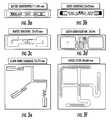
- FIG. 3 aillustrates an example of a large dipole-type transponder
- FIG. 3 billustrates another example of a large dipole-type transponder
- FIG. 3 cillustrates another example of a large dipole-type transponder
- FIG. 3 dillustrates another example of a large dipole-type transponder
- FIG. 3 eillustrates an example of a large two port IC dipole-type transponder
- FIG. 3 fillustrates another example of a large two port IC dipole-type transponder
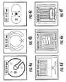
- FIG. 4 aillustrates an example of a small loop-type transponder
- FIG. 4 billustrates another example of a small loop-type transponder
- FIG. 4 cillustrates another example of a small loop-type transponder
- FIG. 4 dillustrates another example of a small loop-type transponder
- FIG. 4 eillustrates another example of a small loop-type transponder
- FIG. 4 fillustrates yet another example of a small loop-type transponder
- FIG. 5is a simplified top view of a co-centered dipole-type transponder and a microstrip near-field antenna in a center-justified system
- FIG. 6is a simplified top view of a co-centered loop-type transponder and a microstrip near-field antenna in a center-justified system
- FIG. 7is a graphical illustration of the level of RF power applied to the antenna for activating the loop-type transponder of FIG. 6 as a function of the distance between a leading edge of the transponder and a printline;
- FIG. 8is a simplified top view of a loop-type transponder and a microstrip near-field antenna in a printer-encoder having an edge-justified system
- FIG. 9is a graphical illustration of the power level for activating the loop-type transponder of FIG. 8 as a function of distance from a printline;
- FIG. 10is a simplified top view of a loop-type transponder and a coplanar waveguide near-field antenna in a printer-encoder having an edge-justified system;
- FIG. 11is a graphical illustration of the power level for activating the loop-type transponder of FIG. 10 as a function of distance from a printline;
- FIG. 12is a top view of a coplanar waveguide near-field antenna according to another exemplary embodiment
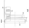
- FIG. 13 ais a bottom view of a ribbon guide and a near-field antenna assembly according to an exemplary embodiment
- FIG. 13 bis a side view of the ribbon guide and the near-field antenna assembly of FIG. 13 a taken along line 13 b - 13 b;
- FIG. 13 cis a side view of the assembly of FIG. 13 a , a platen roller, and a stream of media units;
- FIG. 14 ais a graphical illustration of the current distribution along the length of a dipole-type antenna
- FIG. 14 bis an illustration of the magnetic and electric field distribution of a dipole-type antenna
- FIG. 15 ais a graphical illustration of the characteristic impedance of a conductive strip of a coplanar waveguide as a function of width of the conductive strip;
- FIG. 15 bis a graphical illustration of the characteristic impedance of a conductive strip of a coplanar waveguide as a function of width of the gap of the coplanar waveguide;
- FIG. 16is a top view of a coplanar waveguide near-field antenna according to yet another exemplary embodiment
- FIG. 17is a perspective view of an electromagnetic field distribution of the near-field antenna of FIG. 16 , wherein the characteristic impendence is lower than the terminating loads;
- FIG. 18is a perspective view of an electromagnetic field distribution of the near-field antenna of FIG. 16 , wherein the characteristic impendence is greater than the terminating loads.
- Embodiments of the present inventionconcern an apparatus for enabling an RFID reader to selectively communicate with a targeted transponder that is commingled among or positioned in proximity to multiple adjacent transponders.
- an RFID readerto selectively communicate with a targeted transponder that is commingled among or positioned in proximity to multiple adjacent transponders.
- various embodiments of the present inventionare described below that selectively communicate with a targeted transponder requiring little to no electromagnetic isolation of the transponder through the use space-consuming shielded housings, anechoic chambers, or relatively more complex or costly collision management techniques.
- Several embodiments of the present inventionmay be useful for reading, writing, or otherwise encoding passive or active transponders attached to items located on assembly lines, in inventory management centers where on-demand RFID labeling may be needed, or in other similar circumstances, where the transponders are in close proximity to each other.
- one or more transpondersare mounted to or embedded within a label, ticket, card, or other media form that may be carried on a liner or carrier.
- a liner or carriermay not be needed.
- Such RFID enabled labels, tickets, tags, and other media formsare referred to collectively herein as “media units” or as “smart media units.”
- media unitsor as “smart media units.”
- indiciasuch as text, numbers, barcodes, graphics, etc.
- An example of an RFID systemthat may benefit from one or more of the embodiments of the present invention is a RFID enabled printer system, also referred to herein as “printer-encoder” or a RFID print-engine applicators.
- printer-encodersare disclosed in commonly-owned U.S. Pat. Nos. 6,481,907 and 6,848,616, which are hereby incorporated herein by reference.
- FIG. 1illustrates an example of a RFID printer-encoder 120 structured for printing and encoding a series or stream of media units 124 .
- the printer-encoder 120includes several components, such as a printhead 128 , a platen roller 129 , a feed path 130 , a peeler bar 132 , a media exit path 134 , rollers 136 , a carrier exit path 138 , a ribbon take-up spool 140 , a ribbon supply roll 141 , a reader 142 , a controller 145 , and a coplanar waveguide near-field antenna 150 .
- media unitsmay include labels, cards, etc, that are carried by a substrate liner or web 122 .
- the web 122is directed along the feed path 130 and between the printhead 128 and the platen roller 129 for printing indicia onto the media units 124 .
- the ribbon supply roll 141provides a thermal ribbon (not shown for clarity) that extends along a path such that a portion of the ribbon is positioned between the printhead 128 and the media units 124 .
- the printhead 128heats up and presses a portion of the ribbon onto the media units 124 to print indicia.
- the take-up spool 140is configured to receive and spool the used ribbon.
- This printing techniqueis commonly referred to as a thermal transfer printing. However, several other printing techniques may be used including, but not limited to, direct thermal printing, inkjet printing, dot matrix printing, and electro-photographic printing.
- the media unit web 122proceeds to the media exit path 134 where the media units are typically individually removed from the web 122 .
- pre-cut media units 124may be simply peeled from the web 122 using the peeler bar 132 as shown.
- a group of multiple media unitsmay be peeled together and transmitted downstream to an in-line cutter for subsequent separation (not shown).
- Various other known media unit removal techniquesmay be used as will be apparent to one of ordinary skill in the art.
- the web 122may be guided along a path toward the carrier exit path 138 by rollers 136 or other devices once being separated from the media units.
- conveyance systemsTechniques and structures for conveying or guiding the web of media units along the entire feed path of the printer-encoder are generally referred to as conveyance systems.
- the reader 142is configured for generating and transmitting RF communication signals that are broadcasted by the coplanar waveguide near-field antenna 150 located proximate the media feed path 1130 .
- the reader 142 and the coplanar waveguide near-field antenna 150may be referred to collectively as forming at least part of a communication system.
- the communication systemtransmits an electromagnetic wave for establishing, at predetermined reader power levels, a mutual coupling between the reader and a targeted transponder of a media unit that is located in the transponder encoding area, such that data may be read from and written to transponder.
- the electromagnetic wavehas a near-field strength and a far-field strength.
- the strength in the near-fielddiffers from the strength of the far-field.
- the far-fieldis too weak to activate or communicate with any of the transponders, while the near-field is strong enough in the transponder encoding area such that it only activates the transponders in the transponder encoding area.
- the readeris a device configured to generate, process, and receive electrical communication signals.
- similar devicessuch as transmitters, receivers, or transmitter-receivers may be used within this invention.
- “Reader” as used in the present application and the appended claimsrefers to the devices noted above and to any device capable of generating, processing, or receiving electrical and/or electromagnetic signals.
- a readermay be a combination of a receiver and a transmitter.
- the near-field antennamay be near or approximate with the printhead.
- the near-filed antennamay be close enough to the printhead that at least a part of the communication area overlaps the printhead, which may allow the system to encode the shortest possible labels or maintain the shortest pitch between labels.
- the systemmay be configured such that the system is printing indicia onto the media unit while it is interrogating or encoding the transponder of the media unit.
- the close proximity of the near-field antenna and printheadmay be necessary or desirable in order to maintain overall compact design of the system. It may also create a situation in which the interrogation or encoding of a transponder occurs in essentially the same space as any printing operations.
- FIGS. 2 a , 2 b , and 2 cillustrate a coplanar waveguide near-field antenna 250 in accordance with an exemplary embodiment.
- the coplanar waveguide near-field antenna 250is structured in electrical communication with the reader (not shown in FIGS. 2 a , 2 b , and 2 c ) for receiving and broadcasting the signals originating from the reader to the targeted transponder.
- the coplanar waveguide antenna 250includes a first ground plane 252 , a second ground plane 254 , a conductive strip 256 , a dielectric substrate 258 , an RF port 278 and a terminating load 280 .
- the antenna 250may have a third ground plane 259 that extends along a second opposite surface of the dielectric substrate 258 .
- each of the first ground plane 252 , the second ground plane 254 , the conductive strip 256 , and the dielectric substrate 258define a first surface 260 , 261 , 262 , 263 and an opposite second surface 264 , 265 , 266 , 267 .
- the first surface and second surfacedefines a thickness of the element 252 , 254 , 258 .
- Each of the first ground plane 252 , the second ground plane 254 , and the conductive strip 256has a first edge and a second edge defining a width of the element.
- the first and second ground planes 252 , 254extend along the dielectric substrate 258 .
- the second surfaces 260 , 261 of the first and second ground planesextend along the first surface 262 of the dielectric substrate.
- the first and second ground planes 252 , 254may have substantially the same thickness. Therefore, as illustrated, the first surfaces 260 , 262 of the first and second ground planes may be substantially coplanar relative to each other.
- the first and second ground planes 252 , 254may be spaced apart from each other. Specifically, the adjacent edges of the first and second ground planes 252 , 254 may be spaced apart to form an opening 255 of the antenna.
- the opening 255extends between the two facing edges of the first and second ground planes 252 , 254 .
- the width of the opening 255is the distance between the two facing edges of the first and second ground planes 252 , 254 and the length of the opening 255 is the length of the first and second ground planes 252 , 254 .
- the thickness of the opening 255is the distance from the first surface 263 of the dielectric substrate to the first surfaces 260 , 262 of the first and second ground planes.
- the conductive strip 256extends along the dielectric substrate within the opening.
- the conductive strip 256 and the first and second ground planes 252 , 254form a first and a second slot 270 , 272 of the antenna.
- the first slot 270extends between an edge of the first ground plane 252 and the conductive strip 256 and the second slot 272 extends between an edge of the second ground plane 254 and the conductive strip 256 . As illustrated in FIGS.
- the adjacent and facing edges of the first and second ground planes 252 , 254may be substantially parallel to each other and the conductive strip 256 may be substantially co-centric relative to the opening such that the first and second slots 270 , 272 have equal widths along the length of the conductive strip 256 .
- the conductive strip 256may have a thickness substantially equal to the thickness of either the first ground plane 252 or the second ground plane 254 such that the first surface 261 of the conductive strip, the first surface 260 of the first ground plane, and the first surface 262 of the second ground plane are coplanar.
- the dielectric substrate 258 and the first and second ground planes 252 , 254are illustrated as a separate layer of the antenna having a limited width that forms a compact rectangular shape, the general shape of the dielectric substrate and the ground planes may vary between applications.
- the ground planes and the dielectric substratemay be a portion of a relatively larger printed circuit board.
- the dielectric substratemay be made or constructed from various dielectric materials, including but not limited to, plastics, glasses, ceramics, or combinations such as Rogers materials, Isola materials, or woven glass reinforced epoxy laminate, commonly referred to as “FR4” or flame resistant 4.
- FR4woven glass reinforced epoxy laminate
- the method of fabricating the antenna, including the conductive stripmay vary.
- the conductive stripmay also be deposited directly onto the first surface of the dielectric.
- the conductive stripmay be printed or etched onto the surface or buried inside a substrate.
- the conductive strip 256provides a conductive plane for the propagation of electromagnetic waves from the antenna to a targeted transponder.
- the conductive strip 256is fabricated from a conductive material.
- the conductive materialmay be copper, gold, silver, aluminum or combination thereof, or doped silicon or germanium.
- the conductive strip 256has a length extending from a first end, referred to herein as the signal end 274 , to a second end, referred to herein as the loaded end 276 .
- the length of the conductive strip(i.e., the distance between the signal end 274 and the loaded end 276 ) may be approximately equal to one-half the wavelength of a center operating frequency of the near-field antenna or a multiple of one-half the wavelength of a center operating frequency (i.e., the length equals N* ⁇ /2, where N is an integer).
- the coplanar waveguide near-field antennaincludes a third ground plane 259 that is located opposite the dielectric substrate 258 from the other two ground planes 252 , 254
- the physical length of the conductive strip 256may be decreased while the electrical length remains equal to a multiple of one-half the wavelength.
- the coplanar waveguide antenna 250may further include an RF port 278 and a terminating load 280 .
- the signal end 274 of the conductive stripis connected to the RF port 278 .
- the loaded end 276 of the conductive stripis connected to the terminating load 280 .
- the RF port 278connects the reader directly (or indirectly through any form of transmission line) to the antenna.
- the readeris configured to send an electrical signal to the antenna 250 through the RF port 278 .
- the signalpasses through the RF port 278 , the conductive strip 256 , and into the terminating load 280 , which is connected to at least one of the ground planes 252 , 254 , 259 .
- the terminating load 280may vary. As an example, the terminating load 280 may equal 50 ohms to simplify a system impedance match.
- the conductive strip and one or more ground planesoperate as a transmission line, rather than operating as a standing wave radiating antenna or magnetic field generating coil.
- the passing signal in the conductive stripgenerates electromagnetic fields concentrated in the near field region of the conductive strip.
- the electromagnetic fieldsmay be adapted to couple the reader (through the antenna) to a transponder disposed proximate the conductive strip, referred to herein as the transponder encoding area.
- FIGS. 3 a through 3 fillustrate examples of a first common category of transponders referred to as large dipole-type due to the structure of the antennas of the transponders.
- FIGS. 4 a through 4 fillustrate examples of a second common category of transponders referred to as a small loop-type due to the structure of the antennas of the transponders.
- Terms such as “large” and “small”are intended to indicate the relative size of the transponders compared to an operational wavelength of the transponder.
- the large dipole-typemay be about 3 inches wide (i.e., the largest dimension of the dipole-type) and the small loop-type may be about 1 inches wide.
- a near-field antenna based on a microstrip or stripline transmission lineis generally placed cross-wise relative to the feeding path or feeding direction such that length of the conductive strip of the near-field antenna is orthogonal to the feeding path or feeding direction.
- the alignment of the media units within the printer-encodermay be referred to as either edge-justified (also referred to as side-justified) or center-justified.
- FIG. 8illustrates an example of an edge-justified system.
- the media unit 810 and, thus, the transponder 812are positioned near or aligned with the edge 852 of the near-field antenna 850 regardless of the relative sizes of the media unit 810 and the near-field antenna 850 .
- the width of the media unit 810is smaller than the length of the near-field antenna 850 and the center of the transponder 812 is aligned with an end of the conductive strip of the near-field antenna 850 .
- FIGS. 5 and 6illustrate examples of a center justified system.
- the media unit 510 , 610 and thus, the transponder 512 , 612is positioned proximate to the center of the conductive strip of the near-field antenna 550 , 650 regardless of the relative sizes of the media unit 510 , 610 and the near-field antenna 550 , 650 .
- the media unit 610 of FIG. 6is narrower than the near-field antenna 650 , the center of the transponder is aligned with the center of the conductive strip of the near-field antenna 650 .
- microstrip and stripline near-field antennashave a limited RF power efficiency because their electric field distribution is concentrated between the conductive strip and the ground planes and the field strength above the conductive strip is relatively weak.
- the maximum strength of the magnetic field component emitting from the conductive strip of a stripline or microstrip near-field antennais at the center of the conductive strip and the maximum strength of the electric field component emitting from the conductive strip of a stripline or microstrip near-field antenna is at the edges of the conductive strip as illustrated in FIGS. 14 a and 14 b .
- the electric and magnetic field components from the stripline or microstrip near-field antennamay be optimally aligned with the center of the transponder to facilitate reliable communication between the transponder and the reader through the near-field antenna as illustrated in FIG. 5 .
- a large dipole-type transpondermay be large enough relative to the near-field antenna that even in an edge-justified system the transponder is close enough to the center of the conductive strip not to make a significant difference in the microstrip or stripline near-field antenna's ability to communicate with the transponder in the edge-justified system compared to a center-justified system.
- a stripline or microstrip near-field antennamay by incapable of providing reliable communication with transponders at a desired or acceptable power level depending on whether the system is edge-justified or center-justified.
- the loop-type transponder 612is generally aligned with the center of the microstrip near-field antenna 650 , where the magnetic field strength is the greatest. Such an alignment allows for reliable communication at an acceptable power level.
- the center-justified systemmay include a platen roller 620 that defines a printline of the system (i.e., the point at which the printhead prints indicia onto the media unit) and the near-field antenna 650 may be position d adjacent to the platen roller 620 .
- the near-field antennamay be positioned directly in front of the platen roller such that the near-field antenna is inside the printer-encoder or behind the platen roller such that the near-field antenna is at least partially or complete outside the printer-encoder. As illustrated in FIG.
- the microstrip near-field antennamay be able to activate the transponder from a distance approximately 45 mm to 34 mm and 32 mm to 20 mm from the printline at a power level (i.e., the power provided by the reader) below 23 dBm.
- the transponder 812may be off-set from the center of the near-field antenna 850 such that communication between the transponder 812 and the near-field antenna 850 may require relatively higher power levels as illustrated in FIG. 9 .
- Acceptable power levelsmay be determined based on one or more factors including, but not limited to, the power level available from the reader and regulations or laws limiting maximum power levels.
- one factor that may be consideredis relative power levels. For example, as illustrated in FIGS. 7 and 9 , it takes more power to activate a loop-type transponder in an edge-justified system than a center-justified system.
- a near-field antenna based on a coplanar waveguide 250has extended magnetic field components along its edges (i.e., along the entire length of the conductive strip) as illustrated in FIG. 2 c .
- Loop-type transponderswhich are mostly an IC matching loop, are practically sensitive only to the magnetic component of an electromagnetic field. As the transponder passes over the edges and slots of the coplanar waveguide near-field antenna 250 , the magnetic flux may intersect the transponder and induce voltage and current sufficient to energize the transponder and provide reliable communication.
- the coplanar waveguide near-field antenna 1050may provide reliable communication with a small loop-type transponder 1012 even in an edge-justified system at relative low power levels (e.g., 10-15 dBm) compared to a microstrip near-field antenna.
- an antenna based on a half wavelength microstrip or stripline transmission lineis typically configured to have a characteristic impedance lower then a terminating load impedance.
- the higher impedance ratiocreates a higher standing wave ratio (“SWR”).
- SWRstanding wave ratio
- the width of a conductive stripis the most influencing impedance parameter among other antenna parameters.
- the width of the conductive striphas an inverse relationship with the characteristic impedance. Therefore, a lower characteristic impedance of the conductive strip can be achieved by increasing the width of the conductive strip.
- the transponder encoding areais also dependent of the width. Widening the conductive strip for a higher SWR may also extend the transponder encoding area such that the area is longer than one media unit. A transponder encoding area longer than one media unit may create situations in which more than one transponder is activated at the same time or increase a minimum media unit length, which, as explained above, is an undesirable outcome.
- the characteristic impedance of a near-field antenna based on a half wavelength coplanar waveguideis dependent on the width of the conductive strip and the width of the slots. As illustrated in FIGS. 15 a and 15 b , the width of the slots is a more predominate factor compared to the width of the conductive strip.
- a near-field antenna based on coplanar waveguidemay achieve a high SWR without an increase of a conductive strip width.
- a near-field antenna based on a coplanar waveguide having a terminating load of 50 ohms to simplify antenna port impedance matching and a characteristic impedance of 23 Ohms achieved by having a gap width of 0.31 mm and a strip width of 3 mmcreates a SWR of approximately 2.17.
- a similar near-filed antenna based on a microstrip transmission line having a conductive strip width of 3 mmwould achieve a characteristic impedance of almost 50 Ohm and a SWR of approximately 1.
- the bandwidth of the coplanar waveguide near-field antennamay be increased by implementing a tapered width for each of the slots while keeping a strip width constant.
- the same techniquehas been used to increase a bandwidth for antennas based on microstrip and stripline transmission lines as further discussed in “UHF RFID Antennas for Printer-Encoders-Part 2: Antenna Types”, High Frequency Electronics, Vol. 6, No. 10, October 2007, pp. 36-45, which is authored by one of the inventors of the present application and is hereby incorporated by reference in its entirety.
- the opening 1255 defined by the space between the first and second ground planes 1252 , 1254may have a tapered shape similar to a tapered profile of a conductive strip of either a microstrip or stripline near-field antenna to increase bandwidth.
- the width of each of the first and second slots 1270 , 1272increases at the same constant rate or any other function of width/distance rate from the signal end 1274 to the center and back to the loaded end 1276 .
- the near-field antennamay be desirable to position the near-field antenna near the printhead to facilitate a compact design of the entire system.
- minimizing the distance between the printline and the near-field antennamay be limited due to the structure and dimensions of the platen roller.
- FIGS. 13 a , 13 b and 13 cillustrate an exemplary embodiment of such an assembly 1300 .
- the assembly 1300includes a ribbon guide 1310 and a near field antenna 1350 .
- the ribbon guide 1310is configured to guide or direct the thermal ribbon 1312 between the printhead 1314 and a platen roller 1320 such that the printhead 1322 can heat up and press a portion of the ribbon 1312 against the media unit 1324 located between the platen roller 1320 and the printhead 1322 .
- the ribbon guide 1310includes a recessed portion 1326 configured to receive the near-field antenna 1350 .
- the assembly 1300allows for a compact arrangement between the printhead 1322 , the ribbon guide 1310 , the platen roller 1320 , and the near-field antenna 1350 .
- the operating frequency or operating frequency band of the near-field antenna and the transponders discussed hereinmay vary.
- the near-field antenna and the transpondersmay be configured to operate in ultra high frequencies (“UHF”) (i.e., 300 MHz-3 GHz) or super high frequencies (“SHF”) (i.e., 3 GHz-30 GHz), sometimes called the microwave band.
- UHFultra high frequencies
- SHFsuper high frequencies
- FIG. 16 through FIG. 18illustrate additional embodiments of a near-field antenna based on coplanar waveguide.
- an odd feeding modeis provided for a half wavelength (or multiple thereof) near field antenna based on coplanar waveguide 1650 .
- the near-field antenna 1650may include a phase inverter 1680 configured to generate two signals, each 180 degrees out of phase with each other, to the conductive strip 1656 and ground planes 1652 , 1654 such that the voltage applied between the conductive strip 1656 and the first ground plane 1652 has an inverse phase in regards to voltage applied between a conductive strip 1656 and the second ground plane 1654 .
- the phase inverter 1680may be a transformer which could also be used for impedance matching purposes.
- the near-field antenna 1650may further include a first terminating load 1680 and a second terminating load 1681 .
- the loaded end 1676 of the conductive stripmay be connected to the first ground plane 1652 via the first terminating load 1680 and connected to the second ground plane 1654 via the second terminating load 1681 .
- the ratio of the characteristic impedance of the near-field antenna based on a coplanar waveguide 1650 and the terminating load or loads 1680 , 1681may be configured to achieve a particular pattern of the electric and magnetic field distribution above the slots 1670 , 1672 and the conductive strip 1656 .
- the magnetic field distributionincludes a transverse component and a longitudinal component.
- the magnetic field at each of the edges of the near-field antenna 1650has a unipolar magnetic flux mostly concentrated in longitudinal planes 1781 , 1782 and in the vicinity of the longitudinal planes 1781 , 1782 .
- a transponder encoding area for a single UHF loop type transponder(along the feeding direction) can be achieved by the parallel alignment of the UHF loop type transponder with near-field antenna based on a coplanar waveguide 1650 .
- the magnetic field at the edges of the near-field antenna 1650has magnetic flux concentrated within two opposite transverse components 1883 , 1884 from the ground planes.
- the transponder encoding area(along a feeding direction) is split in two corresponding with the two transverse components 1883 , 1884 .
Landscapes
- Engineering & Computer Science (AREA)
- Physics & Mathematics (AREA)
- General Physics & Mathematics (AREA)
- Theoretical Computer Science (AREA)
- Artificial Intelligence (AREA)
- Computer Vision & Pattern Recognition (AREA)
- Health & Medical Sciences (AREA)
- Toxicology (AREA)
- Computer Networks & Wireless Communication (AREA)
- Electromagnetism (AREA)
- General Health & Medical Sciences (AREA)
- General Engineering & Computer Science (AREA)
- Details Of Aerials (AREA)
- Waveguide Aerials (AREA)
Abstract
Description
Claims (28)
Priority Applications (3)
| Application Number | Priority Date | Filing Date | Title |
|---|---|---|---|
| US11/959,033US9108434B2 (en) | 2007-12-18 | 2007-12-18 | RFID near-field antenna and associated systems |
| PCT/US2008/086375WO2009079326A1 (en) | 2007-12-18 | 2008-12-11 | Rfid near-field antenna and associated systems |
| GB201010531AGB2468448B (en) | 2007-12-18 | 2008-12-11 | RFID Near-Field antenna and associated systems |
Applications Claiming Priority (1)
| Application Number | Priority Date | Filing Date | Title |
|---|---|---|---|
| US11/959,033US9108434B2 (en) | 2007-12-18 | 2007-12-18 | RFID near-field antenna and associated systems |
Publications (2)
| Publication Number | Publication Date |
|---|---|
| US20090152353A1 US20090152353A1 (en) | 2009-06-18 |
| US9108434B2true US9108434B2 (en) | 2015-08-18 |
Family
ID=40751908
Family Applications (1)
| Application Number | Title | Priority Date | Filing Date |
|---|---|---|---|
| US11/959,033Active2033-12-12US9108434B2 (en) | 2007-12-18 | 2007-12-18 | RFID near-field antenna and associated systems |
Country Status (3)
| Country | Link |
|---|---|
| US (1) | US9108434B2 (en) |
| GB (1) | GB2468448B (en) |
| WO (1) | WO2009079326A1 (en) |
Cited By (6)
| Publication number | Priority date | Publication date | Assignee | Title |
|---|---|---|---|---|
| US20170323124A1 (en)* | 2012-09-10 | 2017-11-09 | Avery Dennison Retail Information Services, Llc | Method for preventing unauthorized diversion of nfc tags |
| US10540527B2 (en) | 2012-10-18 | 2020-01-21 | Avery Dennison Retail Information Services Llc | Method, system and apparatus for NFC security |
| US10607238B2 (en) | 2011-09-01 | 2020-03-31 | Avery Dennison Corporation | Apparatus, system and method for consumer tracking consumer product interest using mobile devices |
| US10970496B2 (en) | 2012-11-19 | 2021-04-06 | Avery Dennison Retail Information Services, Llc | NFC tags with proximity detection |
| US10977965B2 (en) | 2010-01-29 | 2021-04-13 | Avery Dennison Retail Information Services, Llc | Smart sign box using electronic interactions |
| US10977969B2 (en) | 2010-01-29 | 2021-04-13 | Avery Dennison Retail Information Services, Llc | RFID/NFC panel and/or array used in smart signage applications and method of using |
Families Citing this family (17)
| Publication number | Priority date | Publication date | Assignee | Title |
|---|---|---|---|---|
| US8314702B2 (en)* | 2009-01-13 | 2012-11-20 | Mastercard International, Inc. | Methods and systems for activating a proximity information device |
| US20100214080A1 (en)* | 2009-02-24 | 2010-08-26 | Sensormatic Electronics Corporation | Radio frequency identification hardtag encode and feed system |
| US8878652B2 (en) | 2009-11-13 | 2014-11-04 | Zih Corp. | Encoding module, associated encoding element, connector, printer-encoder and access control system |
| DE102010009214B4 (en)* | 2010-02-25 | 2018-01-25 | Kathrein-Werke Kg | Modular RFID antenna |
| JP2012103942A (en)* | 2010-11-11 | 2012-05-31 | Oki Data Corp | Ic tag communication device |
| TWI431534B (en) | 2011-11-16 | 2014-03-21 | Ind Tech Res Inst | Radio frequency identification tag and diaper, absorber and sensing system using the same |
| DE102012107291B4 (en)* | 2012-08-08 | 2020-02-13 | HARTING Stiftung & Co. KG | RFID tag with polarization-independent antenna |
| DE102012016655A1 (en)* | 2012-08-24 | 2014-05-15 | Checkpoint Systems, Inc. | System for RFID communication |
| US10592794B2 (en) | 2014-10-13 | 2020-03-17 | Avery Dennison Retail Information Services, Llc | Industrial printer |
| CA2963883C (en)* | 2014-10-13 | 2023-03-28 | Avery Dennison Retail Information Services, Llc | A thermal printer with a quick release cover |
| US10089505B1 (en)* | 2015-09-29 | 2018-10-02 | Amazon Technologies, Inc. | Inventory tracking using RFID |
| US10262172B1 (en) | 2015-09-29 | 2019-04-16 | Amazon Technologies, Inc. | Inventory tracking using RFID |
| US10037449B1 (en) | 2015-09-29 | 2018-07-31 | Amazon Technologies, Inc. | Inventory tracking using RFID |
| KR101687921B1 (en)* | 2015-11-20 | 2016-12-19 | 울산대학교 산학협력단 | Multi-Band Type Antenna |
| CN109950690B (en)* | 2017-12-21 | 2020-11-17 | 华为技术有限公司 | Antenna and terminal |
| JP7455406B2 (en)* | 2019-10-21 | 2024-03-29 | 株式会社システムジャパン | Antenna device and furniture with the antenna device |
| US10963772B1 (en)* | 2020-04-18 | 2021-03-30 | HCL Technologies Italy S.p.A. | Multi radio frequency identification (RFID) device with selective activation of RFID tags |
Citations (87)
| Publication number | Priority date | Publication date | Assignee | Title |
|---|---|---|---|---|
| US2812501A (en) | 1954-03-04 | 1957-11-05 | Sanders Associates Inc | Transmission line |
| US3665480A (en) | 1969-01-23 | 1972-05-23 | Raytheon Co | Annular slot antenna with stripline feed |
| US3742319A (en) | 1971-03-08 | 1973-06-26 | Communications Transistor Corp | R f power transistor |
| US4063249A (en)* | 1974-11-16 | 1977-12-13 | Licentia Patent-Verwaltungs-G.M.B.H. | Small broadband antenna having polarization sensitive reflector system |
| US4371876A (en) | 1978-05-04 | 1983-02-01 | Motorola Inc. | Slot array antenna having a complex impedance termination and method of fabrication |
| US4509039A (en) | 1983-07-05 | 1985-04-02 | Minnesota Mining And Manufacturing Company | Shielded, closely spaced transmit-receiver antennas for electronic article surveillance system |
| EP0414628A2 (en) | 1989-08-25 | 1991-02-27 | George W. Kaltner | Individually fed multiloop antennas for electronic security systems |
| US5006812A (en) | 1989-08-01 | 1991-04-09 | Rockwell International Corporation | Power amplifier with built-in test circuit |
| US5192954A (en) | 1981-02-13 | 1993-03-09 | Mark Iv Transportation Products Corporation | Roadway antennae |
| EP0568067A1 (en) | 1992-04-29 | 1993-11-03 | Texas Instruments Incorporated | RFID system with controlled charge |
| EP0568066A1 (en) | 1992-04-29 | 1993-11-03 | Texas Instruments Incorporated | A method of interrogating a plurality of transponders arranged in the transmission range of an interrogating device and transponders for use in the said method |
| US5278571A (en) | 1991-10-16 | 1994-01-11 | Tel Instrument Electronics Corp. | RF coupler for measuring RF parameters in the near-field |
| US5317646A (en) | 1992-03-24 | 1994-05-31 | Xerox Corporation | Automated method for creating templates in a forms recognition and processing system |
| US5369381A (en)* | 1990-05-29 | 1994-11-29 | U.S. Philips Corporation | Slow-wave transmission line of the microstrip type and circuit including such a line |
| US5373266A (en) | 1993-11-09 | 1994-12-13 | The United States Of America As Represented By The Secreatry Of The Army | Microstrip directional coupler |
| JPH07235826A (en) | 1994-02-21 | 1995-09-05 | Nippon Telegr & Teleph Corp <Ntt> | Slot antenna power feeding circuit and electronic circuit integrated antenna |
| EP0704815A2 (en) | 1994-09-30 | 1996-04-03 | Hughes Identification Devices, Inc. | High field programmable transponder system and method |
| US5521601A (en) | 1995-04-21 | 1996-05-28 | International Business Machines Corporation | Power-efficient technique for multiple tag discrimination |
| US5587578A (en) | 1994-08-10 | 1996-12-24 | Gemplus | Method and apparatus for optimizing magnetic flux through an electronic label of a contact-free identification system |
| US5608417A (en) | 1994-09-30 | 1997-03-04 | Palomar Technologies Corporation | RF transponder system with parallel resonant interrogation series resonant response |
| US5652711A (en) | 1995-03-23 | 1997-07-29 | Agfa Gevaert, N.V. | Parallel processing of page description language data stream |
| US5777586A (en) | 1993-03-17 | 1998-07-07 | Luxon; Norval N. | Radiation shielding and range extending antenna assembly |
| GB2321551A (en) | 1996-03-22 | 1998-07-29 | John Wolfgang Halpern | Reading smartcards |
| DE9321478U1 (en) | 1992-08-01 | 1998-08-27 | Diehl Ident GmbH, 90478 Nürnberg | Device for inductive high-frequency interrogation of identification labels |
| US5838253A (en) | 1995-05-17 | 1998-11-17 | Accu-Sort Systems, Inc. | Radio frequency identification label |
| US5983243A (en) | 1996-10-31 | 1999-11-09 | International Business Machines Corporation | Data processing system and method for Preparing a presentation-ready document that produces separate images of fixed and variable data and a bookticket specifying an arrangement of such images |
| US6012083A (en) | 1996-09-24 | 2000-01-04 | Ricoh Company Ltd. | Method and apparatus for document processing using agents to process transactions created based on document content |
| US6067475A (en) | 1998-11-05 | 2000-05-23 | Urologix, Inc. | Microwave energy delivery system including high performance dual directional coupler for precisely measuring forward and reverse microwave power during thermal therapy |
| US6104291A (en) | 1998-01-09 | 2000-08-15 | Intermec Ip Corp. | Method and apparatus for testing RFID tags |
| US6118379A (en) | 1997-12-31 | 2000-09-12 | Intermec Ip Corp. | Radio frequency identification transponder having a spiral antenna |
| US6154137A (en) | 1998-06-08 | 2000-11-28 | 3M Innovative Properties Company | Identification tag with enhanced security |
| US6177872B1 (en) | 1998-03-13 | 2001-01-23 | Intermec Ip Corp. | Distributed impedance matching circuit for high reflection coefficient load |
| US6181287B1 (en) | 1997-03-10 | 2001-01-30 | Precision Dynamics Corporation | Reactively coupled elements in circuits on flexible substrates |
| US6215402B1 (en) | 1998-03-13 | 2001-04-10 | Intermec Ip Corp. | Radio frequency identification transponder employing patch antenna |
| WO2001035320A1 (en) | 1999-11-08 | 2001-05-17 | Commissariat A L'energie Atomique | Transponder system adapted to ambient noise level |
| US6246326B1 (en) | 1999-05-05 | 2001-06-12 | Intermec Ip Corp. | Performance optimized smart label printer |
| US6267521B1 (en) | 1995-09-22 | 2001-07-31 | Eltron International, Inc. | Computer driven printer with a stripper roller and latching assembly |
| US20010029857A1 (en) | 1998-10-07 | 2001-10-18 | Miguel Heredia | Printer with a device for the driving of transponder chips |
| US20020003498A1 (en) | 2000-05-17 | 2002-01-10 | Luc Wuidart | Electromagnetic field generation antenna for a transponder |
| US6346881B1 (en) | 2000-03-01 | 2002-02-12 | Samsys Technologies Inc. | Tag evaluation module for radio frequency identification (RFID) systems |
| US6392544B1 (en) | 2000-09-25 | 2002-05-21 | Motorola, Inc. | Method and apparatus for selectively activating radio frequency identification tags that are in close proximity |
| US6409401B1 (en) | 2000-03-30 | 2002-06-25 | Zih Corp. | Portable printer with RFID encoder |
| US6421018B1 (en) | 2001-05-31 | 2002-07-16 | Andrew Corporation | Bowtie inductive coupler |
| US6424262B2 (en) | 1998-08-14 | 2002-07-23 | 3M Innovative Properties Company | Applications for radio frequency identification systems |
| EP1224607A1 (en) | 1999-10-18 | 2002-07-24 | Lucatron AG | Method for selecting and writing into rfid-transponders |
| US20020109637A1 (en)* | 2001-02-09 | 2002-08-15 | Toshiya Kitagawa | Antenna apparatus |
| FR2822594A1 (en) | 2001-03-20 | 2002-09-27 | Thomson Csf | Multilayer planar antenna has via grounding to buried ground plane at orthogonal connector |
| US6466131B1 (en) | 1996-07-30 | 2002-10-15 | Micron Technology, Inc. | Radio frequency data communications device with adjustable receiver sensitivity and method |
| US6470082B1 (en) | 1995-06-19 | 2002-10-22 | Nippon Telegraph And Telephone Corporation | Communications system using portable recording medium |
| US6473028B1 (en) | 1999-04-07 | 2002-10-29 | Stmicroelectronics S.A. | Detection of the distance between an electromagnetic transponder and a terminal |
| US20020167397A1 (en) | 1999-07-08 | 2002-11-14 | Kursat Eroglu | Method and apparatus for verifying rfid tags |
| US6486769B1 (en) | 1999-12-22 | 2002-11-26 | Intermec Ip Corp. | Method and system for automatic adjustment and diagnosis of radio frequency identification systems using programmable checktags |
| US6527356B1 (en) | 2000-06-02 | 2003-03-04 | Eastman Kodak Company | Printer capable of forming an image on a receiver substrate according to type of receiver substrate and a method of assembling the printer |
| US20030063001A1 (en) | 2001-10-01 | 2003-04-03 | Hohberger Clive P. | Method and apparatus for associating on demand certain selected media and value-adding elements |
| JP2003132330A (en) | 2001-10-25 | 2003-05-09 | Sato Corp | RFID label printer |
| US6593853B1 (en) | 2000-02-18 | 2003-07-15 | Brady Worldwide, Inc. | RFID label printing system |
| US20030173408A1 (en) | 2002-03-18 | 2003-09-18 | Precision Dynamics Corporation | Enhanced identification appliance |
| US6624718B2 (en) | 2000-12-14 | 2003-09-23 | Intel Corporation | Signal transmission unit |
| US20030224805A1 (en) | 2002-05-28 | 2003-12-04 | Pioneer Corporation | Apparatus and method for detecting leaving of cellular telephone |
| EP1394719A1 (en) | 2002-09-02 | 2004-03-03 | EM Microelectronic-Marin SA | Adaptation of the transmission and receiving characteristic of a RFID reader dependent on the electromagnetic background noise |
| US20040095242A1 (en) | 2000-11-03 | 2004-05-20 | Grose Darren J. | Method and apparatus for tracking carcasses |
| US20040178267A1 (en) | 2003-03-11 | 2004-09-16 | Zebra Technologies Corporation | System and Method for Selective Communication with RFID Transponders |
| US20040195319A1 (en) | 2003-04-03 | 2004-10-07 | Forster Ian J. | RFID device detection system and method |
| US6802659B2 (en) | 1996-08-07 | 2004-10-12 | Mats Cremon | Arrangement for automatic setting of programmable devices and materials therefor |
| US20040203605A1 (en) | 2002-03-05 | 2004-10-14 | Safa John Aram | Security arrangement |
| US20050032267A1 (en) | 2003-08-05 | 2005-02-10 | Peikang Liu | RFID device and method of making |
| US20050045724A1 (en) | 2003-08-29 | 2005-03-03 | Zih Corp. | Spatially Selective UHF Near Field Microstrip Coupler Device and RFID Systems Using Device |
| WO2005022445A2 (en) | 2003-08-29 | 2005-03-10 | Zih Corp. | Spatially selective uhf near field microstrip coupler device and rfid systems using device |
| US6899476B1 (en) | 2003-09-12 | 2005-05-31 | Printronix, Inc. | RFID tag, antenna, and printer system |
| US6938976B2 (en) | 1999-06-16 | 2005-09-06 | Eastman Kodak Company | Printer and method therefor adapted to sense data uniquely associated with a consumable loaded into the printer |
| US20050206524A1 (en) | 2004-03-22 | 2005-09-22 | Forster Ian J | Low cost method of producing radio frequency identification tags with straps without antenna patterning |
| US6969134B2 (en) | 2001-10-01 | 2005-11-29 | Zih Corp. | Printer or other media processor with on-demand selective media converter |
| US20050274799A1 (en)* | 2004-06-10 | 2005-12-15 | Zih Corp. | Apparatus and method for communicating with an RFID transponder |
| US6985754B1 (en) | 1999-04-26 | 2006-01-10 | Nokia Mobile Phones Limited | Radio terminal for browsing the internet |
| US20060037502A1 (en) | 1999-06-16 | 2006-02-23 | Vanguard Identification Systems, Inc. | Printed planar radio frequency identification elements |
| US20060132312A1 (en) | 2004-12-02 | 2006-06-22 | Tavormina Joseph J | Portal antenna for radio frequency identification |
| US7190270B2 (en) | 2004-11-05 | 2007-03-13 | Zih Corp. | System and method for detecting transponders used with printer media |
| US20070063843A1 (en) | 2005-09-21 | 2007-03-22 | Zih Corp. | Multi-layered efficient RFID coupler |
| US20070080867A1 (en) | 2005-09-26 | 2007-04-12 | Hae-Won Son | Antenna using proximity-coupled feed method, RFID tag having the same, and antenna impedance matching method thereof |
| US20070099566A1 (en) | 2005-10-31 | 2007-05-03 | Zih Corp. | Multi-element RFID coupler |
| KR100714804B1 (en) | 2006-04-18 | 2007-05-04 | 주식회사 세우테크 | RFID Printer |
| US20070216591A1 (en) | 2006-03-09 | 2007-09-20 | Zih Corp., | RFID UHF stripline coupler |
| US20070252702A1 (en)* | 2006-04-26 | 2007-11-01 | Symbol Technologies, Inc. | Wireless rugged mobile data capture device with integrated RFID reader |
| KR20070116658A (en) | 2005-04-06 | 2007-12-10 | 로무 가부시키가이샤 | Thermal printer and thermal printer with wireless communication function |
| US7342499B2 (en) | 2006-01-26 | 2008-03-11 | Printronix, Inc. | Multi-band RFID encoder |
| US7375633B2 (en) | 2005-07-19 | 2008-05-20 | Smurfit-Stone Container Enterprises, Inc. | Methods and systems for in-line RFID transponder testing |
| US20080238606A1 (en) | 2007-03-30 | 2008-10-02 | Zih Corp. | Near-Field Miniature Coupler |
Family Cites Families (3)
| Publication number | Priority date | Publication date | Assignee | Title |
|---|---|---|---|---|
| DE60110017T2 (en)* | 2000-10-13 | 2006-03-09 | Matsushita Electric Industrial Co., Ltd., Kadoma | Flat wire-fed cavity slot antenna with a frequency-selective feed network for matching to two resonance frequencies |
| JP4747648B2 (en)* | 2005-04-12 | 2011-08-17 | ソニー株式会社 | Antenna device |
| TWI258893B (en)* | 2005-08-16 | 2006-07-21 | Univ Nat Formosa | H-type microstrip planar antenna layout operated in 5.8 GHz band of RFID system |
- 2007
- 2007-12-18USUS11/959,033patent/US9108434B2/enactiveActive
- 2008
- 2008-12-11WOPCT/US2008/086375patent/WO2009079326A1/enactiveApplication Filing
- 2008-12-11GBGB201010531Apatent/GB2468448B/enactiveActive
Patent Citations (104)
| Publication number | Priority date | Publication date | Assignee | Title |
|---|---|---|---|---|
| US2812501A (en) | 1954-03-04 | 1957-11-05 | Sanders Associates Inc | Transmission line |
| US3665480A (en) | 1969-01-23 | 1972-05-23 | Raytheon Co | Annular slot antenna with stripline feed |
| US3742319A (en) | 1971-03-08 | 1973-06-26 | Communications Transistor Corp | R f power transistor |
| US4063249A (en)* | 1974-11-16 | 1977-12-13 | Licentia Patent-Verwaltungs-G.M.B.H. | Small broadband antenna having polarization sensitive reflector system |
| US4371876A (en) | 1978-05-04 | 1983-02-01 | Motorola Inc. | Slot array antenna having a complex impedance termination and method of fabrication |
| US5192954A (en) | 1981-02-13 | 1993-03-09 | Mark Iv Transportation Products Corporation | Roadway antennae |
| US4509039A (en) | 1983-07-05 | 1985-04-02 | Minnesota Mining And Manufacturing Company | Shielded, closely spaced transmit-receiver antennas for electronic article surveillance system |
| US5006812A (en) | 1989-08-01 | 1991-04-09 | Rockwell International Corporation | Power amplifier with built-in test circuit |
| EP0414628A2 (en) | 1989-08-25 | 1991-02-27 | George W. Kaltner | Individually fed multiloop antennas for electronic security systems |
| US5369381A (en)* | 1990-05-29 | 1994-11-29 | U.S. Philips Corporation | Slow-wave transmission line of the microstrip type and circuit including such a line |
| US5278571A (en) | 1991-10-16 | 1994-01-11 | Tel Instrument Electronics Corp. | RF coupler for measuring RF parameters in the near-field |
| US5317646A (en) | 1992-03-24 | 1994-05-31 | Xerox Corporation | Automated method for creating templates in a forms recognition and processing system |
| EP0568066A1 (en) | 1992-04-29 | 1993-11-03 | Texas Instruments Incorporated | A method of interrogating a plurality of transponders arranged in the transmission range of an interrogating device and transponders for use in the said method |
| US5294931A (en) | 1992-04-29 | 1994-03-15 | Texas Instruments Deutschland Gmbh | Method of interrogating a plurality of transponders arranged in the transmission range of an interrogating device and transponders for use in the said method |
| EP0568067A1 (en) | 1992-04-29 | 1993-11-03 | Texas Instruments Incorporated | RFID system with controlled charge |
| DE9321478U1 (en) | 1992-08-01 | 1998-08-27 | Diehl Ident GmbH, 90478 Nürnberg | Device for inductive high-frequency interrogation of identification labels |
| US5777586A (en) | 1993-03-17 | 1998-07-07 | Luxon; Norval N. | Radiation shielding and range extending antenna assembly |
| US5373266A (en) | 1993-11-09 | 1994-12-13 | The United States Of America As Represented By The Secreatry Of The Army | Microstrip directional coupler |
| JPH07235826A (en) | 1994-02-21 | 1995-09-05 | Nippon Telegr & Teleph Corp <Ntt> | Slot antenna power feeding circuit and electronic circuit integrated antenna |
| US5587578A (en) | 1994-08-10 | 1996-12-24 | Gemplus | Method and apparatus for optimizing magnetic flux through an electronic label of a contact-free identification system |
| US5608417A (en) | 1994-09-30 | 1997-03-04 | Palomar Technologies Corporation | RF transponder system with parallel resonant interrogation series resonant response |
| EP0704815A2 (en) | 1994-09-30 | 1996-04-03 | Hughes Identification Devices, Inc. | High field programmable transponder system and method |
| US5652711A (en) | 1995-03-23 | 1997-07-29 | Agfa Gevaert, N.V. | Parallel processing of page description language data stream |
| US5521601A (en) | 1995-04-21 | 1996-05-28 | International Business Machines Corporation | Power-efficient technique for multiple tag discrimination |
| US5838253A (en) | 1995-05-17 | 1998-11-17 | Accu-Sort Systems, Inc. | Radio frequency identification label |
| US6470082B1 (en) | 1995-06-19 | 2002-10-22 | Nippon Telegraph And Telephone Corporation | Communications system using portable recording medium |
| US6267521B1 (en) | 1995-09-22 | 2001-07-31 | Eltron International, Inc. | Computer driven printer with a stripper roller and latching assembly |
| GB2321551A (en) | 1996-03-22 | 1998-07-29 | John Wolfgang Halpern | Reading smartcards |
| US6466131B1 (en) | 1996-07-30 | 2002-10-15 | Micron Technology, Inc. | Radio frequency data communications device with adjustable receiver sensitivity and method |
| US6802659B2 (en) | 1996-08-07 | 2004-10-12 | Mats Cremon | Arrangement for automatic setting of programmable devices and materials therefor |
| US6012083A (en) | 1996-09-24 | 2000-01-04 | Ricoh Company Ltd. | Method and apparatus for document processing using agents to process transactions created based on document content |
| US5983243A (en) | 1996-10-31 | 1999-11-09 | International Business Machines Corporation | Data processing system and method for Preparing a presentation-ready document that produces separate images of fixed and variable data and a bookticket specifying an arrangement of such images |
| US6181287B1 (en) | 1997-03-10 | 2001-01-30 | Precision Dynamics Corporation | Reactively coupled elements in circuits on flexible substrates |
| US6118379A (en) | 1997-12-31 | 2000-09-12 | Intermec Ip Corp. | Radio frequency identification transponder having a spiral antenna |
| US6104291A (en) | 1998-01-09 | 2000-08-15 | Intermec Ip Corp. | Method and apparatus for testing RFID tags |
| US6177872B1 (en) | 1998-03-13 | 2001-01-23 | Intermec Ip Corp. | Distributed impedance matching circuit for high reflection coefficient load |
| US6215402B1 (en) | 1998-03-13 | 2001-04-10 | Intermec Ip Corp. | Radio frequency identification transponder employing patch antenna |
| US6154137A (en) | 1998-06-08 | 2000-11-28 | 3M Innovative Properties Company | Identification tag with enhanced security |
| US6424262B2 (en) | 1998-08-14 | 2002-07-23 | 3M Innovative Properties Company | Applications for radio frequency identification systems |
| US20010029857A1 (en) | 1998-10-07 | 2001-10-18 | Miguel Heredia | Printer with a device for the driving of transponder chips |
| US6327972B2 (en) | 1998-10-07 | 2001-12-11 | Meto International Gmbh | Printer with a device for the driving of transponder chips |
| US6067475A (en) | 1998-11-05 | 2000-05-23 | Urologix, Inc. | Microwave energy delivery system including high performance dual directional coupler for precisely measuring forward and reverse microwave power during thermal therapy |
| US6473028B1 (en) | 1999-04-07 | 2002-10-29 | Stmicroelectronics S.A. | Detection of the distance between an electromagnetic transponder and a terminal |
| US6985754B1 (en) | 1999-04-26 | 2006-01-10 | Nokia Mobile Phones Limited | Radio terminal for browsing the internet |
| US6246326B1 (en) | 1999-05-05 | 2001-06-12 | Intermec Ip Corp. | Performance optimized smart label printer |
| US6938976B2 (en) | 1999-06-16 | 2005-09-06 | Eastman Kodak Company | Printer and method therefor adapted to sense data uniquely associated with a consumable loaded into the printer |
| US20060037502A1 (en) | 1999-06-16 | 2006-02-23 | Vanguard Identification Systems, Inc. | Printed planar radio frequency identification elements |
| US20020167397A1 (en) | 1999-07-08 | 2002-11-14 | Kursat Eroglu | Method and apparatus for verifying rfid tags |
| EP1224607A1 (en) | 1999-10-18 | 2002-07-24 | Lucatron AG | Method for selecting and writing into rfid-transponders |
| WO2001035320A1 (en) | 1999-11-08 | 2001-05-17 | Commissariat A L'energie Atomique | Transponder system adapted to ambient noise level |
| US6486769B1 (en) | 1999-12-22 | 2002-11-26 | Intermec Ip Corp. | Method and system for automatic adjustment and diagnosis of radio frequency identification systems using programmable checktags |
| US6593853B1 (en) | 2000-02-18 | 2003-07-15 | Brady Worldwide, Inc. | RFID label printing system |
| US6346881B1 (en) | 2000-03-01 | 2002-02-12 | Samsys Technologies Inc. | Tag evaluation module for radio frequency identification (RFID) systems |
| US6409401B1 (en) | 2000-03-30 | 2002-06-25 | Zih Corp. | Portable printer with RFID encoder |
| US20020003498A1 (en) | 2000-05-17 | 2002-01-10 | Luc Wuidart | Electromagnetic field generation antenna for a transponder |
| US7023391B2 (en) | 2000-05-17 | 2006-04-04 | Stmicroelectronics S.A. | Electromagnetic field generation antenna for a transponder |
| US6527356B1 (en) | 2000-06-02 | 2003-03-04 | Eastman Kodak Company | Printer capable of forming an image on a receiver substrate according to type of receiver substrate and a method of assembling the printer |
| US20030067504A1 (en) | 2000-06-02 | 2003-04-10 | Spurr Robert W. | Printer capable of forming an image on a receiver substrate according to type of receiver substrate and a method of assembling the printer |
| US6392544B1 (en) | 2000-09-25 | 2002-05-21 | Motorola, Inc. | Method and apparatus for selectively activating radio frequency identification tags that are in close proximity |
| US20040095242A1 (en) | 2000-11-03 | 2004-05-20 | Grose Darren J. | Method and apparatus for tracking carcasses |
| US6624718B2 (en) | 2000-12-14 | 2003-09-23 | Intel Corporation | Signal transmission unit |
| EP1233367A2 (en) | 2001-02-09 | 2002-08-21 | Omron Corporation | Antenna apparatus |
| US20020109637A1 (en)* | 2001-02-09 | 2002-08-15 | Toshiya Kitagawa | Antenna apparatus |
| FR2822594A1 (en) | 2001-03-20 | 2002-09-27 | Thomson Csf | Multilayer planar antenna has via grounding to buried ground plane at orthogonal connector |
| US6421018B1 (en) | 2001-05-31 | 2002-07-16 | Andrew Corporation | Bowtie inductive coupler |
| US6857714B2 (en) | 2001-10-01 | 2005-02-22 | Zih Corp. | Method and apparatus for associating on demand certain selected media and value-adding elements |
| US6969134B2 (en) | 2001-10-01 | 2005-11-29 | Zih Corp. | Printer or other media processor with on-demand selective media converter |
| US20030063001A1 (en) | 2001-10-01 | 2003-04-03 | Hohberger Clive P. | Method and apparatus for associating on demand certain selected media and value-adding elements |
| JP2003132330A (en) | 2001-10-25 | 2003-05-09 | Sato Corp | RFID label printer |
| US20040203605A1 (en) | 2002-03-05 | 2004-10-14 | Safa John Aram | Security arrangement |
| US20030173408A1 (en) | 2002-03-18 | 2003-09-18 | Precision Dynamics Corporation | Enhanced identification appliance |
| US20030224805A1 (en) | 2002-05-28 | 2003-12-04 | Pioneer Corporation | Apparatus and method for detecting leaving of cellular telephone |
| US7142815B2 (en) | 2002-09-02 | 2006-11-28 | Em Microelectronics-Marin Sa | Adjustment of the detection, transmission and/or reception parameters of an RFID reader as a function of ambient electromagnetic noise |
| EP1394719A1 (en) | 2002-09-02 | 2004-03-03 | EM Microelectronic-Marin SA | Adaptation of the transmission and receiving characteristic of a RFID reader dependent on the electromagnetic background noise |
| US6848616B2 (en) | 2003-03-11 | 2005-02-01 | Zih Corp., A Delaware Corporation With Its Principal Office In Hamilton, Bermuda | System and method for selective communication with RFID transponders |
| US20040178267A1 (en) | 2003-03-11 | 2004-09-16 | Zebra Technologies Corporation | System and Method for Selective Communication with RFID Transponders |
| US20040195319A1 (en) | 2003-04-03 | 2004-10-07 | Forster Ian J. | RFID device detection system and method |
| US20050032267A1 (en) | 2003-08-05 | 2005-02-10 | Peikang Liu | RFID device and method of making |
| US20050045723A1 (en) | 2003-08-29 | 2005-03-03 | Zih Corp. | Spatially Selective UHF Near Field Microstrip Coupler Device and RFID Systems Using Device |
| WO2005022445A2 (en) | 2003-08-29 | 2005-03-10 | Zih Corp. | Spatially selective uhf near field microstrip coupler device and rfid systems using device |
| US20050045724A1 (en) | 2003-08-29 | 2005-03-03 | Zih Corp. | Spatially Selective UHF Near Field Microstrip Coupler Device and RFID Systems Using Device |
| US7398054B2 (en) | 2003-08-29 | 2008-07-08 | Zih Corp. | Spatially selective UHF near field microstrip coupler device and RFID systems using device |
| EP1820659A2 (en) | 2003-08-29 | 2007-08-22 | ZIH Corp. | Spatially selective UHF near field microstrip coupler device and RFID systems using device |
| US6929412B1 (en) | 2003-09-12 | 2005-08-16 | Printronix, Inc. | RFID tag, antenna, and printer system |
| US6899476B1 (en) | 2003-09-12 | 2005-05-31 | Printronix, Inc. | RFID tag, antenna, and printer system |
| US7037009B2 (en) | 2003-09-12 | 2006-05-02 | Printronix | RFID tag, antenna, and printer system |
| US20050206524A1 (en) | 2004-03-22 | 2005-09-22 | Forster Ian J | Low cost method of producing radio frequency identification tags with straps without antenna patterning |
| US20050274799A1 (en)* | 2004-06-10 | 2005-12-15 | Zih Corp. | Apparatus and method for communicating with an RFID transponder |
| US20070176781A1 (en) | 2004-11-05 | 2007-08-02 | Zih Corp. | System and method for detecting transponders used with printer media |
| US7190270B2 (en) | 2004-11-05 | 2007-03-13 | Zih Corp. | System and method for detecting transponders used with printer media |
| US20060132312A1 (en) | 2004-12-02 | 2006-06-22 | Tavormina Joseph J | Portal antenna for radio frequency identification |
| KR20070116658A (en) | 2005-04-06 | 2007-12-10 | 로무 가부시키가이샤 | Thermal printer and thermal printer with wireless communication function |
| US7375633B2 (en) | 2005-07-19 | 2008-05-20 | Smurfit-Stone Container Enterprises, Inc. | Methods and systems for in-line RFID transponder testing |
| US20070063843A1 (en) | 2005-09-21 | 2007-03-22 | Zih Corp. | Multi-layered efficient RFID coupler |
| US7425887B2 (en) | 2005-09-21 | 2008-09-16 | Zih Corporation | Multi-layered efficient RFID coupler |
| US20070080867A1 (en) | 2005-09-26 | 2007-04-12 | Hae-Won Son | Antenna using proximity-coupled feed method, RFID tag having the same, and antenna impedance matching method thereof |
| US20070099566A1 (en) | 2005-10-31 | 2007-05-03 | Zih Corp. | Multi-element RFID coupler |
| US7342499B2 (en) | 2006-01-26 | 2008-03-11 | Printronix, Inc. | Multi-band RFID encoder |
| US20070216591A1 (en) | 2006-03-09 | 2007-09-20 | Zih Corp., | RFID UHF stripline coupler |
| US20070262873A1 (en) | 2006-03-09 | 2007-11-15 | Zih Corp. | Rfid uhf stripline antenna-coupler |
| US7586410B2 (en) | 2006-03-09 | 2009-09-08 | Zih Corp. | RFID UHF stripline coupler |
| KR100714804B1 (en) | 2006-04-18 | 2007-05-04 | 주식회사 세우테크 | RFID Printer |
| US20070252702A1 (en)* | 2006-04-26 | 2007-11-01 | Symbol Technologies, Inc. | Wireless rugged mobile data capture device with integrated RFID reader |
| US20080238606A1 (en) | 2007-03-30 | 2008-10-02 | Zih Corp. | Near-Field Miniature Coupler |
Non-Patent Citations (28)
| Title |
|---|
| Boris Y. Tsirline; UHF RFID Antennas for Printer-Encoders-Part 2: Antenna Types; High Frequency Electronics; Oct. 2007; pp. 36-45 (8 pgs.); Summit Technical Media, LLC. |
| Boris Y. Tsirline; UHF RFID Antennas for Printer-Encoders-Part 3: Mobile Equipment; High Frequency Electronics; Nov. 2007; pp. 18-25 (5 pgs.); Summit Technical Media, LLC. |
| Boris Y. Tsirline; UHF RFID Antennas for Printer-Encoders-Part I: System Requirements; High Frequency Electronics; Sep. 2007; pp. 28-39 (8 pgs.); Summit Technical Media, LLC. |
| Constantine A. Balanis; Chapter 2-Fundamental Parameters of Antennas: Paragraph 2.2.4-Field Regions; Antenna Theory: Analysis and Design; 2005; pp. 34-36; Third Edition; John Wiley & Sons, Inc. |
| David M. Pozar; Paragraph 2.5-The Quarter-Wave Transformer; Microwave Engineering; 2005; pp. 73-76; Third Edition; John Wiley & Sons, Inc. |
| International Search Report and Written Opinion for International Appl. No. PCT/US2007/063680, mailed Jul. 26, 2007. |
| International Search Report and Written Opinion for International Application PCT/US2004/027832, mailed May 6, 2005. |
| International Search Report for corresponding International Application No. PCT/US2008/086375. |
| K.C. Gupta, Ramesh Garg, Inder Bahl, Prakash Bhartia, Microstrip Lines and Slotlines, Second Edition, 1996, Artech House, Inc. |
| Maloratsky, Couplers Shrink HF/VHF/UHF Designs, Microwaves & RF, pp. 93-96, Jun. 2000, USA. |
| Maloratsky, Design Regular-and Irregular-Print Coupled Lines, Microwaves & RF, pp.97-106, Sep. 2000 USA. |
| Maloratsky, Improve BPF Performance With Wiggly Coupled Lines, Microwaves & RF, pp. 53-62, Apr. 2002, USA. |
| Maloratsky, Reviewing the Basics of Microstrip Lines, Microwaves & RF, pp. 79-88, Mar. 2000, USA. |
| Maloratsky, Reviewing the Basics of Suspended Striplines, Microwave Journal, Oct. 2002, USA; 5 pages. |
| Maloratsky, The Basics of Print Reciprocal Dividers/Combiners, Microwave Journal, Sep. 2000, USA; 15 pages. |
| Maloratsky, Understand the Basics of Microstrip Directional Couplers, Microwaves & RF, pp. 79-94, Feb. 2001, USA. |
| McMillan, et al., Leaky Fields on Microstrip, Progress in Electromagnetics Research, Pier 17, pp. 323-377, 1997 USA. |
| Notice of Allowance issued May 6, 2009, in U.S. Appl. No. 11/371,785. |
| Office Action issued Dec. 3, 2008, in U.S. Appl. No. 11/371,785. |
| Office Action issued May 16, 2008, in U.S. Appl. No. 11/371,785. |
| Office Action mailed Aug. 18, 2009, in U.S. Appl. No. 11/121,208. |
| Office Action mailed Aug. 5, 2008, in U.S. Appl. No. 11/121,208. |
| Office Action mailed Mar. 18, 2010, in U.S. Appl. No. 11/121,208. |
| Office Action mailed Mar. 25, 2008, in U.S. Appl. No. 11/121,208. |
| Office Action mailed Oct. 26, 2010, in U.S. Appl. No. 11/121,208. |
| Ron Schmitt; Understanding electromagnetic fields and antenna radiation takes (almost) no math; EDN; Mar. 2, 2000; pp. 77-88; available at . |
| Ron Schmitt; Understanding electromagnetic fields and antenna radiation takes (almost) no math; EDN; Mar. 2, 2000; pp. 77-88; available at <http://www.ednmag.com>. |
| Xianming Qing and Ning Yang; 2.45 GHZ Circularly Polarized RFID Reader Antenna; IEEE; 2004; pp. 612-615 (XP10743394). |
Cited By (8)
| Publication number | Priority date | Publication date | Assignee | Title |
|---|---|---|---|---|
| US10977965B2 (en) | 2010-01-29 | 2021-04-13 | Avery Dennison Retail Information Services, Llc | Smart sign box using electronic interactions |
| US10977969B2 (en) | 2010-01-29 | 2021-04-13 | Avery Dennison Retail Information Services, Llc | RFID/NFC panel and/or array used in smart signage applications and method of using |
| US10607238B2 (en) | 2011-09-01 | 2020-03-31 | Avery Dennison Corporation | Apparatus, system and method for consumer tracking consumer product interest using mobile devices |
| US20170323124A1 (en)* | 2012-09-10 | 2017-11-09 | Avery Dennison Retail Information Services, Llc | Method for preventing unauthorized diversion of nfc tags |
| US10282572B2 (en)* | 2012-09-10 | 2019-05-07 | Avery Dennison Retail Information Services, Llc | Method for preventing unauthorized diversion of NFC tags |
| US10540527B2 (en) | 2012-10-18 | 2020-01-21 | Avery Dennison Retail Information Services Llc | Method, system and apparatus for NFC security |
| US11126803B2 (en) | 2012-10-18 | 2021-09-21 | Avery Dennison Corporation | Method, system and apparatus for NFC security |
| US10970496B2 (en) | 2012-11-19 | 2021-04-06 | Avery Dennison Retail Information Services, Llc | NFC tags with proximity detection |
Also Published As
| Publication number | Publication date |
|---|---|
| WO2009079326A1 (en) | 2009-06-25 |
| GB2468448A (en) | 2010-09-08 |
| US20090152353A1 (en) | 2009-06-18 |
| GB2468448B (en) | 2012-11-07 |
| GB201010531D0 (en) | 2010-08-04 |
Similar Documents
| Publication | Publication Date | Title |
|---|---|---|
| US9108434B2 (en) | RFID near-field antenna and associated systems | |
| US7586410B2 (en) | RFID UHF stripline coupler | |
| EP2261835B1 (en) | Multi-element RFID coupler | |
| US9994043B2 (en) | Near field coupling devices and associated systems and methods | |
| WO2007038063A1 (en) | Multi-layered rfid coupler | |
| US20150136852A1 (en) | Encoding module, associated encoding element, connector, printer-encoder and access control system | |
| US7839287B2 (en) | Near-field miniature coupler |
Legal Events
| Date | Code | Title | Description |
|---|---|---|---|
| AS | Assignment | Owner name:ZIH CORP., BERMUDA Free format text:ASSIGNMENT OF ASSIGNORS INTEREST;ASSIGNORS:TSIRLINE, BORIS Y.;TORCHALSKI, KARL;REEL/FRAME:020264/0208 Effective date:20071217 | |
| AS | Assignment | Owner name:MORGAN STANLEY SENIOR FUNDING, INC. AS THE COLLATERAL AGENT, MARYLAND Free format text:SECURITY AGREEMENT;ASSIGNORS:ZIH CORP.;LASER BAND, LLC;ZEBRA ENTERPRISE SOLUTIONS CORP.;AND OTHERS;REEL/FRAME:034114/0270 Effective date:20141027 Owner name:MORGAN STANLEY SENIOR FUNDING, INC. AS THE COLLATE Free format text:SECURITY AGREEMENT;ASSIGNORS:ZIH CORP.;LASER BAND, LLC;ZEBRA ENTERPRISE SOLUTIONS CORP.;AND OTHERS;REEL/FRAME:034114/0270 Effective date:20141027 | |
| STCF | Information on status: patent grant | Free format text:PATENTED CASE | |
| AS | Assignment | Owner name:JPMORGAN CHASE BANK, N.A., AS THE SUCCESSOR AGENT, NEW YORK Free format text:PATENT SECURITY INTEREST ASSIGNMENT AGREEMENT;ASSIGNOR:MORGAN STANLEY SENIOR FUNDING, INC., AS THE EXISTING AGENT;REEL/FRAME:044791/0842 Effective date:20170907 Owner name:JPMORGAN CHASE BANK, N.A., AS THE SUCCESSOR AGENT, Free format text:PATENT SECURITY INTEREST ASSIGNMENT AGREEMENT;ASSIGNOR:MORGAN STANLEY SENIOR FUNDING, INC., AS THE EXISTING AGENT;REEL/FRAME:044791/0842 Effective date:20170907 | |
| MAFP | Maintenance fee payment | Free format text:PAYMENT OF MAINTENANCE FEE, 4TH YEAR, LARGE ENTITY (ORIGINAL EVENT CODE: M1551); ENTITY STATUS OF PATENT OWNER: LARGE ENTITY Year of fee payment:4 | |
| AS | Assignment | Owner name:ZEBRA TECHNOLOGIES CORPORATION, ILLINOIS Free format text:MERGER;ASSIGNOR:ZIH CORP.;REEL/FRAME:048884/0618 Effective date:20181220 | |
| AS | Assignment | Owner name:JPMORGAN CHASE BANK, N.A., AS COLLATERAL AGENT, NE Free format text:NOTICE OF TRANSFER OF SECURITY INTEREST IN PATENTS;ASSIGNOR:ZEBRA TECHNOLOGIES CORPORATION;REEL/FRAME:049675/0049 Effective date:20190701 Owner name:JPMORGAN CHASE BANK, N.A., AS COLLATERAL AGENT, NEW YORK Free format text:NOTICE OF TRANSFER OF SECURITY INTEREST IN PATENTS;ASSIGNOR:ZEBRA TECHNOLOGIES CORPORATION;REEL/FRAME:049675/0049 Effective date:20190701 | |
| CC | Certificate of correction | ||
| AS | Assignment | Owner name:JPMORGAN CHASE BANK, N.A., NEW YORK Free format text:SECURITY INTEREST;ASSIGNORS:ZEBRA TECHNOLOGIES CORPORATION;LASER BAND, LLC;TEMPTIME CORPORATION;REEL/FRAME:053841/0212 Effective date:20200901 | |
| AS | Assignment | Owner name:ZEBRA TECHNOLOGIES CORPORATION, ILLINOIS Free format text:RELEASE OF SECURITY INTEREST - 364 - DAY;ASSIGNOR:JPMORGAN CHASE BANK, N.A.;REEL/FRAME:056036/0590 Effective date:20210225 Owner name:LASER BAND, LLC, ILLINOIS Free format text:RELEASE OF SECURITY INTEREST - 364 - DAY;ASSIGNOR:JPMORGAN CHASE BANK, N.A.;REEL/FRAME:056036/0590 Effective date:20210225 Owner name:TEMPTIME CORPORATION, NEW JERSEY Free format text:RELEASE OF SECURITY INTEREST - 364 - DAY;ASSIGNOR:JPMORGAN CHASE BANK, N.A.;REEL/FRAME:056036/0590 Effective date:20210225 | |
| MAFP | Maintenance fee payment | Free format text:PAYMENT OF MAINTENANCE FEE, 8TH YEAR, LARGE ENTITY (ORIGINAL EVENT CODE: M1552); ENTITY STATUS OF PATENT OWNER: LARGE ENTITY Year of fee payment:8 |