US9107674B2 - Systems and methods employing a guidewire for positioning and stabilizing external instruments deployed within the body - Google Patents
Systems and methods employing a guidewire for positioning and stabilizing external instruments deployed within the bodyDownload PDFInfo
- Publication number
- US9107674B2 US9107674B2US13/854,662US201313854662AUS9107674B2US 9107674 B2US9107674 B2US 9107674B2US 201313854662 AUS201313854662 AUS 201313854662AUS 9107674 B2US9107674 B2US 9107674B2
- Authority
- US
- United States
- Prior art keywords
- guidewire
- distal
- expandable structure
- lumen
- tail
- Prior art date
- Legal status (The legal status is an assumption and is not a legal conclusion. Google has not performed a legal analysis and makes no representation as to the accuracy of the status listed.)
- Expired - Fee Related, expires
Links
Images


Classifications
- A—HUMAN NECESSITIES
- A61—MEDICAL OR VETERINARY SCIENCE; HYGIENE
- A61B—DIAGNOSIS; SURGERY; IDENTIFICATION
- A61B18/00—Surgical instruments, devices or methods for transferring non-mechanical forms of energy to or from the body
- A61B18/04—Surgical instruments, devices or methods for transferring non-mechanical forms of energy to or from the body by heating
- A61B18/12—Surgical instruments, devices or methods for transferring non-mechanical forms of energy to or from the body by heating by passing a current through the tissue to be heated, e.g. high-frequency current
- A61B18/14—Probes or electrodes therefor
- A61B18/1492—Probes or electrodes therefor having a flexible, catheter-like structure, e.g. for heart ablation
- A—HUMAN NECESSITIES
- A61—MEDICAL OR VETERINARY SCIENCE; HYGIENE
- A61B—DIAGNOSIS; SURGERY; IDENTIFICATION
- A61B1/00—Instruments for performing medical examinations of the interior of cavities or tubes of the body by visual or photographical inspection, e.g. endoscopes; Illuminating arrangements therefor
- A61B1/00147—Holding or positioning arrangements
- A61B1/00154—Holding or positioning arrangements using guiding arrangements for insertion
- A—HUMAN NECESSITIES
- A61—MEDICAL OR VETERINARY SCIENCE; HYGIENE
- A61M—DEVICES FOR INTRODUCING MEDIA INTO, OR ONTO, THE BODY; DEVICES FOR TRANSDUCING BODY MEDIA OR FOR TAKING MEDIA FROM THE BODY; DEVICES FOR PRODUCING OR ENDING SLEEP OR STUPOR
- A61M16/00—Devices for influencing the respiratory system of patients by gas treatment, e.g. ventilators; Tracheal tubes
- A61M16/04—Tracheal tubes
- A61M16/0488—Mouthpieces; Means for guiding, securing or introducing the tubes
- A61M16/049—Mouthpieces
- A61M16/0493—Mouthpieces with means for protecting the tube from damage caused by the patient's teeth, e.g. bite block
- A—HUMAN NECESSITIES
- A61—MEDICAL OR VETERINARY SCIENCE; HYGIENE
- A61M—DEVICES FOR INTRODUCING MEDIA INTO, OR ONTO, THE BODY; DEVICES FOR TRANSDUCING BODY MEDIA OR FOR TAKING MEDIA FROM THE BODY; DEVICES FOR PRODUCING OR ENDING SLEEP OR STUPOR
- A61M25/00—Catheters; Hollow probes
- A61M25/01—Introducing, guiding, advancing, emplacing or holding catheters
- A61M25/02—Holding devices, e.g. on the body
- A61M2025/024—Holding devices, e.g. on the body having a clip or clamp system
Definitions
- the inventiongenerally relates to systems and methods for inserting and securing the position of an external instrument, such as a catheter tube, in the body, e.g., through the oral cavity and into the esophagus for the treatment of gastric esophageal reflux disease (GERD).
- an external instrumentsuch as a catheter tube
- the inventionprovides systems and methods for treating a tissue region.
- the systems and methodsemploy an expandable structure that projects beyond the distal end of a catheter tube.
- a distal tailprojects beyond the far end of the basket assembly.
- the distal tailincludes a guidewire lumen that accommodates passage of a guidewire without threading the guidewire through the catheter tube.
- FIG. 1 a - a / 1 a - bis a side view of a bite block and five alternate embodiments of inserts carrying a centrally located gripping tool that may be employed with the bite block.
- FIG. 1 bis a side view of a bite block and an embodiment of an insert carrying an eccentrically located gripping tool that may be employed with the bite block.
- FIG. 1 cis a side view of a bite block and two alternate embodiments of “clip-on” inserts carrying eccentrically located gripping tools that may be employed with the bite block.
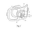
- FIG. 2is a front view of a bite block incorporating an insert carrying a gripping tool with a cam mechanism.
- FIG. 3 ais a schematic of a gripping tool showing the position of a gripping element and actuator mechanism in a closed position.
- FIG. 3 bis a schematic of a gripping tool showing the position of a gripping element and actuator mechanism in an open position.
- FIG. 4 ais a side view of one of the embodiments shown in FIG. 1 a - a.
- FIGS. 4 b - 4 dare front views illustrating the operation of the cam surfaces incorporated in the jaws of the insert shown in FIG. 4 a.
- FIG. 4 eis a side view illustrating the open and closed positions of the jaws of the gripping tool shown in FIG. 4 a.
- FIG. 5 ais a side view of an embodiment shown in FIG. 1 a - a that incorporates a cam mechanism.
- FIG. 5 bis an exploded view of FIG. 5 a.
- FIG. 5 cis a front view of the insert shown in FIG. 5 a.
- FIG. 5 dis a side view of the insert shown in FIG. 5 a , illustrating the position of the cam mechanism in the open position.
- FIG. 5 eis a front view of the insert shown in FIG. 5 a , illustrating the position of the jaws of the gripping tool in the open position.
- FIG. 5 fis a side view of the insert shown in FIG. 5 a , illustrating the position of the jaws of the gripping tool in the open position.
- FIG. 5 gis a side view of the insert shown in FIG. 5 a , illustrating the position of the cam mechanism in the closed position.
- FIG. 5 his a front view of the insert shown in FIG. 5 a , illustrating the position of the jaws of the gripping tool in the closed position.
- FIG. 5 iis a side view of the insert shown in FIG. 5 a , illustrating the position of the jaws of the gripping tool in the open position.
- FIG. 6 ais a side view of an embodiment shown in FIG. 1 a - a that incorporates a C-clamp mechanism.
- FIG. 6 bis an exploded view of FIG. 6 a.
- FIG. 6 cis a front view of the insert shown in FIG. 6 a.
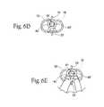
- FIG. 6 dis a front view of the insert shown in FIG. 6 a , illustrating the position of the jaws of the gripping tool in the closed position.
- FIG. 6 eis a front view of the insert shown in FIG. 6 a , illustrating the use of the C-clamp and the position of the jaws of the gripping tool in the open position.
- FIG. 7 ais a side view of an embodiment shown in FIG. 1 a - b that incorporates a prong-clamp mechanism.
- FIG. 7 bis a breakaway view of FIG. 7 a.
- FIG. 7 cis a front view of the insert shown in FIG. 7 a.
- FIG. 7 dis a front view of the insert shown in FIG. 7 a , illustrating the position of the jaws of the gripping tool in the closed position.
- FIG. 7 eis a front view of the insert shown in FIG. 7 a , illustrating the use of the prong clamp and the position of the jaws of the gripping tool in the open position.
- FIG. 8 ais a side view of an embodiment shown in FIG. 1 a - b that incorporates a clothespin-clamp mechanism centrally located within the insert opening.
- FIG. 8 bis a front view of the insert shown in FIG. 8 a.
- FIG. 8 cis a front view of the insert shown in FIG. 8 a , illustrating the position of the jaws of the gripping tool in the closed position.
- FIG. 8 d - 8 fare front views illustrating the insertion of an external instrument into a bite block utilizing the upturned edges incorporated in the jaws of the insert shown in FIG. 8 a.
- FIG. 8 gis a front view of the insert shown in FIG. 8 a , illustrating the use of the clothespin-clamp and the position of the jaws of the gripping tool in the open position.
- FIG. 9 ais a side view of an embodiment shown in FIG. 1 b that incorporates a clothespin-clamp mechanism eccentrically located within the insert opening.
- FIG. 9 bis a front view of the insert shown in FIG. 9 a.
- FIG. 10 ais a side view of a bite block and an embodiment of a clip-type insert shown in FIG. 1 c that may be employed with the bite block.
- FIG. 10 bis a rear view of the insert shown in FIG. 10 a.
- FIG. 10 cis a front view of a bite block incorporating the insert shown in FIG. 10 a.
- FIG. 10 dis rear view of the bite block and incorporated insert shown in FIG. 10 c.
- FIG. 11 ais a side view of a bite block and an embodiment of a clip-type insert shown in FIG. 1 c that may be employed with the bite block.
- FIG. 11 bis a rear view of the insert shown in FIG. 11 a.
- FIG. 11 cis a front view of a bite block incorporating the insert shown in FIG. 11 a.
- FIG. 11 dis rear view of the bite block and incorporated insert shown in FIG. 11 c.
- FIG. 12is a front view of a bite block, showing the insertion of an external instrument through the opening of the bite block alongside a jaw assembly and illustrating the movement required to position the external instrument in the jaw assembly.
- FIG. 13is a front view of a bite block as in FIG. 12 , illustrating the positioning of the external instrument in the jaw assembly.
- FIG. 14 ais a side view of a catheter commonly employed in the treatment of GERD, illustrating an expandable structure in a deflated position and a series of electrodes retracted.
- FIG. 14 bis a side view of the catheter shown in FIG. 14 a , illustrating the expandable structure inflated and the series of electrodes extended.
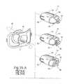
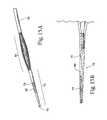
- FIG. 15 ais an enlarged side view of the distal tail of the expandable structure shown in FIGS. 14 a and 14 b.
- FIG. 15 bis a cutaway side view of the distal tail shown in FIG. 15 a , detailing the interior lumen within the tail.
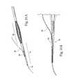
- FIG. 16 ais a side view of a guidewire being threaded through the distal tail.
- FIG. 16 bis a cutaway view of the distal tail illustrating the threading of a guidewire through the interior lumen within the tail.
- FIG. 17is a side view of an individual in a reclined position with a bite block carrying a gripping tool inserted in the individual's mouth.
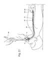
- FIG. 18is a side view of the employment of a guidewire through a bite block carrying a gripping tool and into the esophagus.
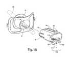
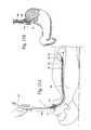
- FIG. 19is a side view of the employment of an endoscope through the bite block carrying a gripping tool and into the esophagus.
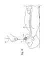
- FIG. 20is a side view illustrating the threading of an employed guidewire through a catheter tip.
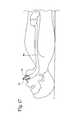
- FIG. 21 ais a side view illustrating the final positions of the guidewire and the catheter after employment.
- FIG. 21 bis an enlarged side view of the lower esophagus and stomach showing the final positions of the guidewire and the catheter after employment.
- FIG. 22is a side view of the jaws of the gripping tool being moved to a closed position by manipulation of a cam mechanism.
- FIG. 23is a side view illustrating the employed catheter with the expandable structure in an inflated position.
- FIG. 24is a side view illustrating the employed catheter with the expandable structure inflated and the electrodes in an extended position.
- FIG. 25is a side view of the jaws of the gripping tool being moved to an open position by manipulation of a cam mechanism, with the expandable structure deflated and the electrodes retracted.
- FIG. 26is a side view of the employed catheter being rotated axially, with the expandable structure deflated and the electrodes retracted.
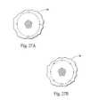
- FIG. 27 ais a schematic of a lesion pattern after one ablation sequence is completed.
- FIG. 27 bis a schematic of a lesion pattern after a second ablation sequence is performed following a 45° rotation of the catheter.
- FIG. 28is a side view of the employed catheter being advanced axially, with the expandable structure deflated and the electrodes retracted.
- FIG. 29is a schematic of a lesion pattern after two ablation sequences separated by 45° are performed at each of four levels.
- FIG. 30is a side view showing the positioning of a catheter within the cardia of the stomach.
- FIG. 31 ais a schematic of a lesion pattern after one ablation sequence.
- FIG. 31 bis a schematic of a lesion pattern after a second ablation sequence is performed following a 22.5° rotation of the catheter.
- FIG. 31 cis a schematic of a lesion pattern after a third ablation sequence is performed following a 22° rotation of the catheter in the opposite direction.
- FIG. 32is a schematic of a lesion pattern after three ablation sequences separated by 22.5° are performed at each of two levels.
- FIG. 33is a side view of a catheter commonly employed in the treatment of GERD, illustrating an expandable structure comprising an array of tubular spines, one of which accommodates passage of a guidewire.
- FIG. 34is a cross-section view of one of the spines of the expandable structure illustrated in FIG. 33 , detailing the interior of the three lumens that make up the spine.
- FIG. 35is a schematic of the exterior surface of a section of the spine shown in FIG. 34 , illustrating the positioning of openings within the lumens and electrode and temperature sensing elements carried within the lumens.
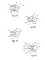
- FIG. 36 ashows an exterior surface of the spine of the expandable structure illustrated in FIG. 33 that accommodates passage of a guidewire.
- FIG. 36 billustrates the interior surface of the spine shown in FIG. 36 a.
- FIG. 37is an exploded view of the expandable structure carried at the distal region of the catheter shown in FIG. 33 , illustrating the guidewire lumen carried by a spine and a two-piece distal guide assembly.
- FIG. 38is a cross-section view of the inner sheath taken generally along line 38 - 38 in FIG. 37 .
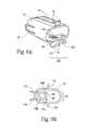
- FIG. 39is a partially assembled side view of the expandable structure shown in FIG. 37 , illustrating the attachment of the inner sheath and the coupling of an expandable body to the inner sheath.
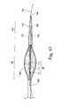
- FIG. 40is a fully assembled side view of the expandable structure shown in FIG. 39 , illustrating the placement of the outer and inner sheath of the guide assembly and depicting a guidewire thread through the distal guide assembly and guidewire lumen.
- FIG. 1 a - a / 1 a - bshows a bite block 10 .
- a bite block 10is commonly used to hold an individual's mouth open during insertion of an instrument into the oral cavity.
- a bite block 10can be utilized during procedures requiring insertion of a catheter tube 19 through the oral cavity into the esophagus 84 , such as in the treatment of gastroesophageal reflux disease (GERD).
- GERDgastroesophageal reflux disease
- the bite block 10may be conventional, formed, e.g., from hard, medical grade plastic by conventional molding techniques.
- Conventional bite blocks 10comprise an opening 11 for insertion of an external instrument 15 (as shown in phantom lines in FIG. 1 a ).
- the opening 11is large enough to readily accommodate insertion of a variety of differently sized and shaped instruments and is therefore not capable of holding an instrument in a fixed or stabilized position.
- One aspect of the inventionprovides for a gripping tool (T) for association with a bite block 10 .
- Eight embodiments of a gripping tool (T 1 -T 8 )are shown in FIGS. 1 a - a / 1 a - b , 1 b , and 1 c .
- Five of the embodiments (T 1 -T 5 )are shown in FIG. 1 a - a / 1 a - b .
- Another embodiment (T 6 )is shown in FIG. 1 b .
- Two additional embodiments (T 7 and T 8 )are shown in FIG. 1 c.
- the gripping tool (T)holds an instrument 15 in a fixed or stabilized position within the oral cavity during a procedure and permits removal of the instrument upon completion of the procedure, as will be described in greater detail later. It further permits the moving of the instrument 15 from one fixed position to an alternate fixed position, as will also be described in greater detail later.
- the inventionpermits the hands of the provider to be freed during the procedure and assures that the instrument 15 will not inadvertently be moved during the procedure.
- the gripping tool (T) or any portion of itmay be integral with the body of the bite block 10 . Alternately, the gripping tool (T) or any portion of it may be part of an insert 12 that is selectively attachable within the opening 11 of the bite block 10 at the instant of use.
- FIGS. 1 a - a / 1 a - b , 1 b , and 1 cshow eight representative embodiments of gripping tools, T 1 to T 8 , each taking the form of an insert 12 insertable into the bite block opening 11 .
- FIG. 2shows a bite block 10 carrying one embodiment of the gripping tool (T 2 ) after insertion into the bite block 10 .
- the inserts 12may be formed, e.g., from hard, medical grade plastic by conventional molding techniques.
- the insert 12is a generally cylindrical hollow body constructed to couple to the bite block 10 upon insertion. As shown in FIGS. 1 a - a / 1 a - b and 1 b , in the illustrated embodiments T 1 -T 6 , the insert 12 comprises at least three features that serve to secure and guide the insert into the proper position within the bite block opening 11 .
- the insert 12includes a top vane 14 and a bottom vane 23 that extend the length of the insert 12 .
- the vanes 14 and 23are tapered so as to secure the insert 12 in proper position within the bite block 10 by making friction fit engagement against the interior wall of the bite block opening 11 .
- a second top vane 14 and a second bottom vane 23may be provided.
- the insert 12includes a stoprest 13 to prevent over insertion of the gripping tool (T).
- the stoprest 13is a straight perpendicular extension of the front edge of any of the vanes 14 or 23 .
- the stoprest 13is located on the top vane 14 .
- the stoprests 13are located on both top vanes 14 and bottom vanes 23 .
- vanes 14 and 23 and stoprests 13can be provided.
- the insert 12also includes first and second lips 16 on opposing sides of the insert 12 .
- the lips 16have a plastic memory so as to engage the rear edge of the bite block 10 in a snap fit when the insert 12 is properly positioned within the bite block opening 11 .
- FIGS. 10 c - 10 dillustrate a bite block 10 carrying one embodiment (T 7 ) of the clip-on insert 12 ′ after insertion into the bite block 10 .
- FIGS. 11 c and 11 dillustrate a bite block 10 carrying another embodiment (T 8 ) of the clip-on insert 12 ′ after insertion into the bite block 10 .
- the insert 12 ′comprises at least three features that serve to secure and guide the insert 12 ′ into the proper position within the bite block opening 11 .
- the insert 12 ′is a member having a “folded” or “curved” shape whereby the insert 12 ′ is adapted to slide over the wall of the bite block 10 on either the right or left side of the opening 11 .
- the “fold” or curve”results in the insert 12 ′ having a first side 94 and a second side 96 .
- the first side 94 of the insert 12 ′is adapted to be positioned in the interior of the opening 11 and rest against the bite block 10 wall when the insert 12 ′ is positioned within the bite block 10 (see FIGS. 11 c and 11 d ).
- the first side 94carries a jaw assembly 18 .
- the second side 96is adapted to be positioned exterior to opening 11 and rest against the bite block 10 wall when the insert 12 is positioned within the bite block 10 .
- the insert 12 ′is curved to prevent rotation within the bite block 10 .
- the opening 11is generally oval shaped.
- the insert 12 ′is shaped so as to match the curvature of the bite block 10 on the right or left side of the bite block 10 , but not necessarily the top or bottom of the bite block 10 .
- FIGS. 10 c and 11 cThis arrangement results in the gripping tool (T) having an eccentric location (see FIGS. 10 c and 11 c ).
- the eccentric locationprovides a larger area in which to insert the external instrument 15 before positioning it within the gripping tool (T).
- the insertion of an external instrument 15 within a bite block 10 carrying an eccentrically located gripping tool (T)is illustrated in FIGS. 12 and 13 .
- an external instrument 15is inserted within the bite block opening 11 . As indicated by arrows in FIG. 12 , the external instrument 15 can then moved laterally to position it within the gripping tool (T).
- FIG. 13illustrates the external instrument 15 positioned within the gripping tool (T).
- the insert 12 ′contains opposed grasping clasps positioned on opposite interior and exterior sides of the bite block 10 wall.
- the construction and number of grasping claspscan vary.
- two outer grasping clasps 98are spaced parallel to each other and positioned to be on one side of the bite block 10 wall when the insert 12 ′ is positioned within the bite block 10 .
- An inner clasp 100is positioned (desirably equidistant) between the outer clasps 98 and positioned to be on the opposite side of the bite block 10 wall from the outer clasps 98 when the insert 12 ′ is positioned within the bite block 10 .
- Each of the clasps 98 and 100has a foot-like appendage 102 extending perpendicularly from the end of the clasps 98 and 100 .
- the foot-like appendages 102are capable of abutting against the back wall of bite block 10 when the insert 12 ′ is positioned within the bite block 10 , such that they provide a snap fit when the insert 12 ′ is positioned within the bite block 10 .
- the purposes of the gripping tool (T)are to accommodate passage of an external instrument 15 through the bite block 10 and to grip the external instrument 15 .
- the gripping tool (T)comprises gripping elements 17 that are selectively movable and capable of pivoting between an open position (P 1 ) (see FIG. 3 b ) and a closed position (P 2 ) (see FIG. 3 a ), such that the distance between the elements 17 is greater in P 1 than in P 2 .
- An actuator mechanism 21effectuates movement of the elements between P 1 and P 2 .
- P 1(shown in FIG. 3 b ) is an open spaced-apart position corresponding to a first distance (D 1 ) between the gripping elements 17 .
- P 2(shown in FIG. 3 a ) is a closed adjacently-spaced position corresponding to a second distance (D 2 ) between the gripping elements 17 , such that D 2 is less than D 1 .
- FIG. 3 bshows, in P 1 the gripping tool (T) accommodates passage of an external instrument 15 through the bite block 10 .
- the gripping tool (T)contacts the periphery of the external instrument 15 , thereby maintaining the instrument 15 in a fixed position within the bite block 10 .
- the gripping tool (T)may take a variety of embodiments, eight of which (T 1 to T 8 ) are shown in FIGS. 1 a - a / 1 a - b , 1 b , and 1 c .
- FIGS. 4 a - 4 edetail one of the embodiments (T 1 ) shown in FIG. 1 a and its use.
- the gripping element 17consists of a jaw assembly 18 carried by the insert 12 .
- the jaw assembly 18comprises a first jaw 40 and a second jaw 42 .
- the jaws 40 and 42extend from the insert 12 at parallel and oppositely spaced locations, thus having interior facing surfaces and exterior non-facing surfaces relative to each other.
- resilient plastic memorybiases the jaws 40 and 42 toward the closed position P 2 .
- the relative positions of the jaws 40 and 42 in P 1 (phantom lines) and P 2 (solid lines)are illustrated in FIG. 4 e.
- each of the jaws 40 and 42includes a first indented cam surface 20 and a pair of second raised cam surfaces 22 on each jaw 40 and 42 flanking the indented cam surface 20 .
- the first cam surface 20comprises an area of reduced thickness in the wall of the jaws 40 and 42 .
- the first cam surfaces 20are normally oppositely spaced at the second distance D 2 , as FIG. 4 d shows, to normally grip the instrument 15 confined between the jaws 40 and 42 , corresponding to position P 2 .
- the second cam surfaces 22comprise areas of greater thickness in the walls of the jaws 40 and 42 .
- FIG. 4 cshows, manipulation of an external instrument 15 between an opposing pair of second cam surfaces 22 causes the jaws 40 and 42 to yield and open.
- the first cam surfaces 20are moved to the first distance D 1 , corresponding to position P 1 , thereby allowing the external instrument 15 to be inserted between the jaws 40 and 42 and removed from the jaws 40 and 42 .
- the jaws 40 and 42are formed to include the resilient plastic memory that, together with the cam surfaces 20 and 22 , provides the actuator mechanism 21 for the jaws 40 and 42 .
- the combination of the plastic memory and the cam surfaces 20 and 22enables the jaws 40 and 42 to be moved so as to pivot selectively between P 1 and P 2 .
- the resilient plastic memoryyields in response to contact between the instrument 15 and the second cam surfaces 22 to allow the external instrument 15 to be inserted between the jaws 40 and 42 (position P 1 to P 2 ) and, likewise, to be removed from the jaws 40 and 42 (position P 2 to P 1 ).
- the jaws 40 and 42are capable of holding an external instrument 15 in a fixed position.
- the jaws 40 and 42are positioned such that the external instrument 15 is not held in a fixed position, allowing it to be inserted or removed.
- the jaws 40 and 42are carried by an insert 12 .
- the jaws 40 and 42may be integral with a bite block 10 .
- FIGS. 5 a - 5 idetail a second embodiment (T 2 ) of the gripping tool shown in FIG. 1 a and its use.
- the gripping element 17consists of a jaw assembly 18 .
- the jaw assembly 18comprises a first jaw 40 and a second jaw 42 carried by the insert 12 .
- the jaws 40 and 42are similar to the jaws 40 and 42 in FIGS. 4 a - 4 e , but need not contain first cam surfaces 20 or second cam surfaces 22 .
- the actuator mechanism 21includes a resilient plastic memory in the jaws 40 and 42 and a cam mechanism 24 coupled to the jaws 40 and 42 .
- this resilient memorybiases the jaws 40 and 42 toward the P 1 , or open position shown in FIGS. 5 d - 5 f .
- Engagement of a series of cam regions on the control knob 26 by manipulation of the cam mechanism 24overcomes this bias and moves the jaws 40 and 42 from the open (P 1 ) position to the closed (P 2 ) position, shown in FIGS. 5 g - 5 i.
- the resilient memorycan bias the jaws 40 and 42 in the P 2 , or closed, position.
- the jaws 40 and 42need not be biased in either position.
- cam mechanism 24can be conventional, formed, e.g., from hard, medical grade plastic by conventional molding techniques.
- FIG. 5 billustrates an embodiment in which the cam mechanism 24 includes a control knob 26 and a pair of control appendages 28 .
- the control appendages 28are connected to the jaws 40 and 42 and engage the control knob 26 .
- the control knob 26rotates on the appendages 28 .
- Each jaw 40 and 42includes a control appendage 28 that extends from the respective jaw 40 or 42 in a perpendicular direction, as best illustrated in FIGS. 5 b - 5 c .
- Rotation of the control knob 26exerts force on the control appendages 28 and thereby opens and closes the jaws 40 and 42 (i.e., moves the jaws 40 and 42 selectively between P 1 and P 2 ).
- the control knob 26takes a ring form having an interior surface and an exterior surface.
- the interior surfaceincludes a pair of diametrically opposed first cam regions 30 .
- a pair of diametrically opposed second cam regions 32are oppositely spaced in the interior surface at a decreased diameter relative to the first cam regions 30 .
- the control appendages 28rest within the interior surface of the control knob 26 in contact with either the first cam regions 30 or the second cam regions 32 .
- Rotation of the control knob 26 in a first directionbrings the first cam regions 30 into contact with the appendages 28 .
- the jaws 40 and 42are positioned such that the external instrument 15 is not held in a fixed position, allowing it to be inserted or removed.
- the jaws 40 and 42are capable of holding an external instrument 15 in a fixed position.
- control knob 26desirably includes first and second grasping extensions to aid in the rotation of the control knob 26 circumferentially upon the appendages 28 .
- a first and second stopguard 36are also desirably provided.
- the stopguards 36prevent over-rotation of the control knob 26 in the first and second directions.
- Rotationthus permits the control knob 26 to move selectively between P 1 , in which the control appendages 28 contact the first cam regions 30 , and P 2 , in which the control appendages 28 contact the second cam regions 32 , thus permitting the jaws 40 and 42 to pivot between the D 1 and D 2 positions.
- P 2the first stopguard 36 rests against the first control appendage 28 and the second stopguard 36 rests against the second control appendage 28 .
- the cam mechanism 24 and jaws 40 and 42are carried by an insert 12 for a bite block 10 .
- the cam mechanism 24 , the jaws 40 and 42 , or bothmay be integral with the bite block 10 .
- FIGS. 6 a - 6 edetail another embodiment (T 3 ) shown in FIG. 1 a and its use.
- the gripping element 17takes the form of jaw assembly 18 comprising a “C-clamp” 38 carried by the insert 12 .
- this C-clamp 38includes levers comprising a first jaw 40 ′, a second jaw 42 ′, and a third jaw 44 .
- the jaws 40 ′, 42 ′, and 44each include a first region 45 and second region 47 .
- the first region 45is generally semi-circle-shaped.
- the second region 47is a straight appendage extending from the end of the first region 45 and serves as a grasping appendage.
- the third jaw 44is a mirror image of the first jaw 40 ′ and the second jaw 42 ′ also having a first region 45 and a second region 47 .
- the C-clamp 38also comprises a post 94 extending from the top of the front surface of the insert 12 .
- the post 94extends through corresponding points on the first region 45 of each jaw 40 ′, 42 ′, and 44 .
- the post 94serves as an axis upon which the jaws 40 ′, 42 ′, and 44 are attached in a hinged fashion such that they may pivot selectively along the axis of the post 94 .
- the first jaw 40 ′is positioned proximal to the front surface of the insert 12 along the axis of the post 94 .
- the third jaw 44is positioned medially along the axis of the post 94 .
- the second jaw 42 ′is positioned distally along the axis of the post.
- the hinged arrangementpermits the jaws 40 ′, 42 ′, and 44 to pivot between a first position (P 1 ) (see FIG. 6 e ) and a second position (P 2 ) (see FIG. 6 d ).
- the second region 47 of the third jaw 44is aligned with the second regions 47 of the first jaw 40 ′ and the second jaw 42 ′. In this position, the three first regions 45 form an opening of a first diameter (D 1 ). This corresponds to an open position, in which an external instrument 15 is not able to be held in a fixed position.
- the second region 47 of the third jaw 44is spaced apart from the second regions 47 of the first jaw 40 ′ and the second jaw 42 ′.
- the first regions 45 of the three jawsform an opening of a second diameter (D 2 ), such that D 2 is less than D 1 .
- D 2a second diameter
- the hinge mechanismprovides a resilient plastic memory and serves as an actuator mechanism 21 that enables the jaws 40 ′, 42 ′, and 44 to be moved so as to pivot selectively between P 1 and P 2 .
- This resilient memorybiases the jaws 40 ′, 42 ′, and 44 toward the closed position P 2 (see FIG. 6 d ).
- Application of “squeezing” pressure (illustrated by arrows in FIG. 6 e ) on the second regions of the jaws 40 ′, 42 ′, and 44overcomes this bias and moves the jaws 40 ′, 42 ′, and 44 from the closed (P 2 ) position to the open (P 1 ) position.
- the C-clamp 38may be conventional, formed, e.g., from hard, medical grade plastic by conventional molding techniques.
- the C-clamp 38is carried by an insert 12 for a bite block 10 .
- the C-clamp 38 or any portion of itmay be integral with the bite block 10 .
- FIGS. 7 a - 7 edetail another embodiment (T 4 ) shown in FIG. 1 a and its use.
- the gripping element 17takes the form of jaw assembly 18 comprising a “prong-clamp” carried by the insert 12 .
- this prong-clamp 38comprises a first jaw 40 and a second jaw 42 .
- the jaws 40 and 42are similar to the jaws 40 and 42 in FIGS. 4 a - 4 e , but need not contain first cam surfaces 20 or second cam surfaces 22 .
- this prong-clamp 46also includes levers comprising a first prong 52 , a second prong 54 , and a third prong 56 .
- the first prong 52 and second prong 54are integral with the first jaw 40 .
- the prongsconsist of a first section 48 and a second section 50 .
- the first section 48extends perpendicularly from the first jaw 40 at a right angle.
- the second section 50extends perpendicularly from the first section 48 at a right angle from the first section 48 .
- the first prong 52 and second prong 54are spaced apart along the first jaw 40 and positioned such that they are parallel to each other.
- the third prong 56is integral with the second jaw 42 and is spaced (desirably equidistant) between the first prong 52 and the second prong 54 .
- the third prong 56consists of a first section 48 and a second section 50 and is essentially a mirror image of the first prong 52 and second prong 54 .
- first section 48extends perpendicularly from the second jaw 42 at a right angle.
- the second section 50extends perpendicularly from the first section 48 at a right angle from the first section 48 and serves as a grasping appendage.
- the jaws 40 and 42possess a resilient plastic memory that serves as an actuator mechanism 21 that enables the jaws 40 and 42 to be moved so as to pivot selectively between P 1 and P 2 .
- the second section 50 of the third prong 56is aligned with the second sections 50 of the first prong and the second prong 54 .
- the three prongsimpart a correspondingly spaced-apart relation to the jaws 40 and 42 corresponding to a first diameter (D 1 ). This corresponds to an open position, in which an external instrument 15 is not able to be held in a fixed position.
- the second section 50 of the third prong 56is spaced apart from the second sections 50 of the first prong 52 and the second prong 54 .
- the three prongsimpart a correspondingly spaced-apart relation to the jaws 40 and 42 corresponding to a second diameter (D 2 ), such that D 2 is less than D 1 .
- D 2a second diameter
- the resilient plastic memorybiases the jaws 40 and 42 toward the closed, or P 2 position.
- Application of “squeezing” pressure (illustrated by arrows in FIG. 7 e ) on the second sections 50 of the prongs 52 , 54 , and 56overcomes this bias and moves the jaws 40 and 42 from the closed (P 2 ) position to the open (P 1 ) position.
- the prong clamp 46may be conventional, formed, e.g., from hard, medical grade plastic by conventional molding techniques.
- the prong-clamp 46 and jaws 40 and 42are carried by an insert 12 for a bite block 10 .
- the prong-clamp 46 or any portion of it, the jaws 40 and 42 , or any combination thereofmay be integral with the bite block 10 .
- FIGS. 8 a - 8 gdetail another embodiment (T 5 ) shown in FIG. 1 a and its use.
- the gripping element 17takes the form of a jaw assembly 18 comprising a “clothespin-type clamp” 104 carried by the insert 12 .
- this clothespin-clamp 104comprises a C-shaped groove 106 .
- the top side of the groove 106comprises a first jaw 40 having an upturned edge 108 .
- the bottom side of groove 106comprises a second jaw 42 having a downturned edge 110 .
- the upturned end downturned edges 108 and 110serve as leading edges that guide the insertion of an external instrument 15 into the groove 104 .
- this clothespin-clamp 104also includes a first arm 112 integral with and extending horizontally from the top of the C-shape and a second arm 114 integral with and extending horizontally from the bottom of the C-shape, positioned such that the first arm and second arms 112 and 114 are parallel to each other.
- the jaws 40 and 42possess a resilient plastic memory that, together with the upturned and downturned edges 106 and 108 and the first and second arms 112 , serve as an actuator mechanism 21 that enables the jaws 40 and 42 to moved so as to pivot selectively between P 1 and P 2 .
- This resilient plastic memorybiases the jaws 40 and 42 toward the closed position P 2 (shown in FIG. 8 c ).
- the resilient plastic memoryyields in response to contact between the instrument 15 and the edges 108 and 110 to move the jaws 40 and 42 from the closed (P 2 ) position to the open (P 1 ) position.
- the jaws 40 and 42assume an open spaced-apart position corresponding to a first diameter (D 1 ) between the jaws 40 and 42 . This corresponds to an open position, illustrated in FIGS. 8 d and 8 g , in which an external instrument 15 is not able to be held in a fixed position.
- the jaws 40 and 42assume their normally biased closed adjacently-spaced position corresponding to a second diameter (D 2 ), such that D 2 is less than D 1 .
- D 2a second diameter
- the clothespin-clamp 104may be conventional, formed, e.g., from hard, medical grade plastic by conventional molding techniques.
- the clothespin-clamp 104is carried by an insert 12 for a bite block 10 .
- the clothespin-clamp 104 or any portion of itmay be integral with the bite block 10 .
- FIGS. 9 a and 9 bdetail another embodiment (T 6 ) shown in FIG. 1 b and its use.
- This embodimentis similar to embodiment T 5 , except that the jaw assembly 18 is adapted to be eccentrically located within the bite block opening 11 when the insert 12 is positioned within the bite block 10 .
- the jaw assembly 18is adapted so as to be centrally located within the bite block opening 11 when the insert 12 is positioned within the bite block 10 .
- the jaw assembly 18 in any of the embodiments T 1 -T 5can be positioned so as to be eccentric, as in embodiment T 6 .
- an eccentric locationprovides for a larger area in which to insert the external instrument 15 before positioning it within the gripping tool (T).
- FIGS. 10 a - 10 ddetail another embodiment (T 7 ) shown in FIG. 1 c and its use.
- FIG. 10 aprovides a C-shaped groove 106 functionally and structurally similar to that contained in embodiment T 6 .
- the C-shaped groove 106is carried by a clip-on insert 12 ′ as previously described.
- the first and second arms 112 and 114are not provided.
- the first side 94 of the insert 12 ′includes the C-shaped groove 106 .
- the groove 106extends perpendicularly from the third clasp 100 .
- the groove 106may be coated with an elastomeric material, making the groove 106 more tacky, thereby aiding in grasping an external instrument. This coating can be accomplished by either placing a tube over the groove 106 or placing a low durameter pad over the groove 106 .
- the second side 96 of the insert 12 ′includes the first and second clasps 98 .
- the first and second clasps 98are positioned exterior to the opening 11 along the bite block 10 wall when the insert 12 ′ is positioned within the bite block 10 .
- the third clasp 100 and groove 106are positioned interior to the opening 11 along the bite block 10 wall when the insert 12 ′ is positioned within the bite block 10 .
- the groove 106is adapted to be positioned eccentrically within the opening 11 when the insert 12 ′ is positioned within the bite block 10 .
- the insert 12 ′can be formed such that the groove 106 is positioned centrally within the opening 11 (not shown).
- the groove 106In the closed position (see FIG. 8 c ), the groove 106 is capable of holding an external instrument 15 in a fixed position. In the open position (see FIG. 8 e ), the groove 106 is positioned such that the external instrument 15 is not held in a fixed position, allowing it to be inserted or removed.
- the C-shaped groove 106may be conventional, formed, e.g., from hard, medical grade plastic by conventional molding techniques.
- the C-shaped groove 106is carried by an insert 12 ′ for a bite block 10 .
- the C-shaped groove 106 or any portion of itmay be integral with the bite block 10 .
- FIGS. 11 a - 11 ddetail another embodiment (T 8 ) shown in FIG. 1 c and its use.
- FIG. 11 aprovides a C-shaped groove 106 mechanism on a clip-on type insert 12 ′ as in embodiment T 7 .
- the first side 94 of the insert 12 ′includes the C-shaped groove 106 as described for embodiment T 7 .
- the groove 106extends perpendicularly from the first and second clasps 98 rather than from the third clasp 100 .
- the second side 96 of the insert 12 ′includes the third clasp 100 .
- the third clasp 100is positioned exterior to the opening 11 along the bite block 10 wall when the insert 12 ′ is positioned within the bite block 10 .
- the first and second clasps 98 and groove 106are positioned interior to the opening 11 along the bite block 10 wall when the insert 12 ′ is positioned within the bite block 10 .
- the groove 106can be coated with an elastomeric material. While the illustrated embodiment shows an eccentric location, the groove 106 can be adapted to be centrally located within the opening 11 when the insert 11 is positioned within the bite block 10 , as previously noted for embodiment T 7 .
- any one of the gripping tools (T 1 -T 8 ) describedcan be used with a catheter 58 designed for the treatment of gastroesophageal reflux disease (GERD).
- a catheter 58 designed for the treatment of gastroesophageal reflux diseaseis shown in FIGS. 14 a and 14 b.
- a catheter 58carries a series of electrodes 60 that, in use, can be coupled to a source of radio frequency energy to ohmically heat tissue and create a lesion in the tissue region, e.g., lower esophageal spinchter 90 (see FIG. 21 b ) or cardia 92 (see FIG. 30 ) or both. It has been discovered that natural healing of the lesions tightens the targeted and adjoining tissue.
- FIGS. 14 a and 14 bshow a representative embodiment for the catheter 58 .
- the catheter 58comprises a catheter tube 19 having a distal region and a proximal region.
- the proximal regionincludes a handle 62 incorporating control mechanisms.
- the distal regioncarries an expandable structure 64 (e.g., suitable for contacting the lower esophageal sphincter 90 during performance of procedures for the treatment of GERD, as shown in FIG. 21 b ).
- the expandable structure 64includes an array of tubular spines 66 that form a basket that is capable of being selectively expanded and contracted.
- the expandable structure 64further comprises an expandable body 68 (e.g., balloon) within the basket.
- the purpose of the expandable body 68is to cause the basket to expand and contract within the esophagus 84 .
- the expanded structure 64serves to temporarily dilate the targeted tissue, thus removing some or all the folds normally present in the mucosal surface.
- FIG. 14 ashows the expandable structure 64 in the contracted or collapsed position.
- FIG. 14 bshows the expandable structure 64 in the expanded position.
- the electrodes 60are carried within the spines 66 and are similarly capable of extension and retraction.
- the electrodes 60are selectively movable between two positions.
- the first positionis a retracted position, illustrated in FIG. 14 a , in which they are withdrawn in a spine 66 .
- the second positionis an extended position, illustrated in FIG. 14 b , in which they extend outward from the spine 66 through a hole in the spine 66 .
- the electrodes 60can be biased with either an antegrade or retrograde bend.
- the electrodes 60can also be arranged in bipolar pairs or in a singular, spaced-apart relation suitable for monopolar operation. In the illustrated embodiment, the electrodes 60 show an antegrade bend and a monopolar arrangement.
- FIGS. 15 a and 15 billustrate an embodiment in which the expandable structure 64 includes a distal tail 72 adapted to accommodate a guidewire 70 .
- the purpose of the guidewire 70is to aid insertion and guidance of the expandable structure 64 and catheter 58 through the oral cavity to a desired position within the esophagus 84 (see FIG. 21 a ).
- the configuration of the distal tail 72eliminates the need to thread the guidewire 70 through the expandable structure 64 and the entire body of the catheter 58 .
- the distal tail 72may be conventional, formed, e.g., from semi-rigid, medical grade plastic (e.g., PebaxTM, polyurethane, silicone, SantopreneTM, or other flexible materials) by conventional molding techniques.
- An interior lumen 74extends through the distal tail 72 .
- the interior lumen 74is a passage that it does not communicate with any other lumen or structure within the body of the catheter 58 .
- the purpose of the interior lumen 74is strictly to permit passage of a guidewire 70 .
- this lumen 74could communicate with irrigation or aspiration lumens (not shown).
- This interior lumen 74terminates at the distal end in an opening 76 in the distal end of the tail 72 .
- the interior lumen 74terminates at the proximal end in an orifice 78 that penetrates the wall of the distal tail 72 .
- the orifice 78is located approximately midway along the distal tail 72 , or about one and one-half inches from the opening 76 .
- a slot 80 along the axis of the distal tail 72is provided in the wall of distal tail 72 .
- the slot 80extends approximately 1% inches.
- the purpose of the slot 80is to aid in threading a guidewire 70 .
- the threading of a guidewire 70 through the slot 80is illustrated in FIGS. 16 a and 16 b.
- the orifice 78is located at the distal end of the slot 80 , such that the guidewire 70 is guided by the slot 80 as it is threaded through the orifice 78 .
- the slot 80does not penetrate the wall of the distal tail 72 , thus it communicates with the interior lumen 74 in the distal tail 72 only through the orifice 78 .
- the proximal end of the slot 80tapers toward the exterior surface of the distal tail 72 , thereby enabling it to guide the guidewire 70 as it is threaded through the distal tail 72 .
- a bite block 10desirably carrying a gripping tool (T) as previously described (see, e.g., FIG. 1 a ) is placed in the patient's mouth and properly positioned, as illustrated in FIG. 17 .
- the gripping elements 17are placed in the open (P 1 ) position (as shown in FIG. 3 b ).
- the physicianpasses the small diameter guidewire 70 through the patient's mouth and pharynx, and into the esophagus 84 to the targeted site, as illustrated in FIG. 18 .
- the targeted site for treatment of GERDis typically the lower esophageal sphincter 90 (see FIG. 21 b ) or the cardia 92 of the stomach (see FIG. 30 ), or both.
- the physicianpreferably employs an endoscope 86 in conjunction with the guidewire 70 for viewing the targeted site.
- an endoscope 86is shown in FIG. 19 .
- the endoscope 86can be either separately employed in a side-by-side relationship with the guidewire 70 , or the endoscope 86 may be introduced over the guidewire 70 itself.
- FIG. 19illustrates employment of an endoscope 86 over a guidewire 70 .
- the tubal body of the endoscope 86includes measured markings 88 along its length.
- the markings 88indicate the distance between a given location along the tubal body and the endoscope 86 .
- the physiciancan gauge, in either relative or absolute terms, the distance between the patient's mouth and the endoscope 86 in the esophagus 84 .
- the physicianvisualizes the desired treatment site, e.g., lower esophageal sphincter 90 (see FIG. 21 b ) or cardia 92 (see FIG. 30 )
- the physicianrecords the markings 88 that align with the bite block 10 and removes the endoscope 86 , leaving the guidewire 70 behind.
- the catheter tube 19includes measured markings 88 along its length.
- the measured markings 88indicate the distance between a given location along the catheter tube 19 and an operative element (e.g., electrodes 60 ).
- the markings 88 on the catheter tube 19correspond in spacing and scale with the measured markings 88 along the tubal body of the endoscope 86 .
- the free proximal end of the guidewire 70is thread through the opening 76 in the distal tail 72 of the expandable structure 64 , such that the guidewire 70 exits the distal tail 72 through the orifice 78 , as illustrated in FIG. 20 .
- the catheter 58is then advanced along the guidewire 70 through the patient's mouth and pharynx and to the desired position in the esophagus 84 , e.g., lower esophageal sphincter 90 .
- the positioning of the catheter 58 in the lower esophageal sphincter 90is illustrated in FIGS. 21 a and 21 b.
- the sequencetypically comprises the following steps. First, the gripping elements 17 of the gripping tool (T) are moved (represented by arrows in FIG. 22 ) to the closed (P 2 ) position (shown in FIG. 3 a ), thereby holding the catheter 58 fixed in the desired position, as shown in FIG. 22 .
- the expandable body 68is expanded (e.g., sterile water or air is injected into a balloon through a port in the handle 62 of the catheter 58 , causing it to inflate).
- the expandable structure 64is thereby also expanded.
- FIG. 23shows the position of the expandable body 68 after expansion.
- the electrodes 60are extended (e.g., by operation of a push-pull lever on the handle 62 of the catheter 58 ), as illustrated in FIG. 24 .
- radio frequency energyis applied for a desired period of time (e.g., radio frequency energy in the range of about 400 kHz to about 10 mHz is applied for approximately 90 seconds).
- cooling liquidcan be introduced during the ablation sequence (e.g., each spine 66 can include an interior lumen with a port to convey a cooling liquid like sterile water into contact with the mucosal surface of the targeted tissue site) (not shown).
- the electrodes 60are retracted (e.g., by operation of a push-pull lever on the handle 62 of the catheter 58 ).
- the expandable structure 64is deflated.
- the elements 17 of the gripping tool (T)are moved to the open (P 1 ) position (shown in FIG. 3 b ), thereby enabling the repositioning or removal of the catheter 58 .
- the opening of the elements 17is illustrated by arrows in FIG. 25 .
- multiple lesionsmay be obtained by performing a series of ablation sequences in both the lower esophageal sphincter 90 (see FIG. 21 b ) and the cardia 92 (see FIG. 30 ).
- the physiciantypically performs a series of ablation sequences in the lower esophageal sphincter 90 , followed by a series of ablation sequences in the cardia 92 , or vice versa.
- a “rotational sequence”is first employed in the lower esophageal sphincter 90 (see FIG. 21 b ).
- the catheter 58is rotated axially a desired number of degrees from the first position, as illustrated by arrows in FIG. 26 .
- the elements 17 of the gripping tool (T)are then moved to the closed (P 2 ) position and a second ablation sequence is performed.
- FIGS. 27 a - 27 bThe pattern of lesions created by such a rotational sequence is shown in FIGS. 27 a - 27 b .
- FIG. 27 acorresponds to the pattern resulting from the initial ablation sequence.
- FIG. 27 brepresents the lesion pattern after one rotation and ablation sequence.
- the lesion patterncorresponds to four electrodes 60 spaced at 90 degree angles on the catheter 58 (see FIG. 27 a ).
- the rotationis of approximately 45 degrees, thereby creating a final lesion pattern comprising a “ring” of eight equidistant lesions (see FIG. 27 b ).
- an “axial sequence”may be employed. This process is illustrated in FIGS. 28-29 . In this sequence, with the elements 17 in an open position, the catheter 58 is advanced axially within the lower esophageal sphincter 90 from the site of the first ablation sequence, as illustrated by arrow in FIG. 28 .
- the elements 17 of the gripping tool (T)are moved to the closed position and a second ablation sequence is then performed. If desired, a rotational sequence is then performed as previously described.
- the catheter 58is then advanced axially from the site of the second ablation sequence and the process is repeated (not shown).
- the catheter 58is then advanced axially from the site of the third ablation sequence and the process is repeated (not shown).
- FIG. 29One possible pattern of lesions formed in the lower esophageal sphincter 90 resulting from such a combination of axial and rotational sequences is illustrated in FIG. 29 .
- FIG. 29corresponds to the lesion pattern resulting from a rotational ablation sequence being performed at each of four different depths within the lower esophageal sphincter 90 .
- eight lesionsare formed at each of four depths, for a total of thirty-two lesions.
- the catheter 58is advanced axially into the cardia 92 .
- the positioning of the catheter within the cardia 92is illustrated in FIG. 30 .
- a first ablation sequenceis then performed.
- a rotational sequenceis then performed if desired. For example, the catheter is rotated a desired number of degrees and a second ablation sequence is performed. The catheter 58 is then rotated the same number of degrees from the site of the first ablation sequence in the opposite direction and a final ablation sequence is performed.
- FIGS. 31 a - 31 cThe pattern of lesions created by such a rotational sequence is shown in FIGS. 31 a - 31 c.
- FIG. 31 acorresponds to the pattern resulting from the initial ablation sequence.
- FIG. 31 brepresents the lesion pattern after the first rotation and ablation sequence.
- FIG. 31 crepresents the lesion pattern after the second rotation and ablation sequence
- the lesion patterncorresponds to four electrodes 60 spaced at 90 degrees angles on the catheter 58 .
- the rotationis of approximately 22.5 degrees, thereby creating a final lesion pattern of twelve lesions.
- FIG. 32represents the final lesion pattern created after the sequence is repeated at a second depth.
- the lesion pattern illustratedis that of twelve lesions created at each two depths, for a total of twenty-four lesions created in the cardia 92 .
- the physicianassures that the electrodes 60 are retracted and the expandable body 68 is contracted (e.g., air or water is withdrawn from the balloon by a syringe through a port on the handle 62 of the catheter 58 ) (not shown).
- the expandable body 68is contracted (e.g., air or water is withdrawn from the balloon by a syringe through a port on the handle 62 of the catheter 58 ) (not shown).
- the elements 17 of the gripping tool (T)are then verified as being in the open position, the catheter 58 and guidewire 70 are withdrawn, and the bite block 10 is removed from the patient's mouth (not shown).
- any one of the gripping tools (T 1 -T 8 ) describedcan also be used with an alternate embodiment of the previously described catheter 58 .
- This alternate embodimentenables the threading of a guidewire 70 outside the body of the catheter 58 , through a guidewire lumen 116 within one of the spines 66 of the expandable structure 64 .
- the expandable structure 64includes an array of spines 66 that form a basket that is capable of being selectively expanded and contracted.
- the expandable structure 64comprises four spines 66 .
- the expandable structure 64can include a greater or lesser number of spines 66 .
- the guidewire lumen 116passes through one of the spines 66 outside the catheter 58 and outside expandable body 68 .
- the guidewire lumen 116further extends beyond the distal end of the expandable structure 64 through a distal guide assembly 133 .
- each of the spines 66 through which the guidewire 70 does not passcomprises three lumens, designated L 1 , L 2 , and L 3 in FIG. 33 and subsequent FIGS. 34-40 .
- An arrangement of lumens of this typeis detailed in co-pending U.S. patent application Ser. No. 09/955,915, filed Sep. 19, 2001, now U.S. Pat. No. 6,699,243, which is herein incorporated by reference.
- the first or center passage L 1carries a movable, elongated electrode element 118 .
- the distal end of the electrode element 118comprises an electrode 60 .
- the electrode element 118has a retracted position, in which the distal end of the electrode element 118 is contained within the spine 66 , and an extended position in which the distal end of the electrode element 118 extends out from the spine 66 and is capable of piercing tissue.
- FIG. 35shows the distal end of the electrode element 118 in an extended position. When extended, the electrode 60 exits L 1 through an electrode opening 120 .
- a third passage L 3 along side the first passage L 1is coupled to tubing 123 that carries processing fluid from a fluid delivery device.
- fluidis passed through L 3 and exits L 3 through an irrigation opening 122 .
- the irrigation opening 122can be generally aligned with the electrode opening 120 so that ablation and cooling occur in the same general tissue region.
- the irrigation opening 122can be proximal or distal to the electrode opening 120 .
- a second passage L 2 alongside the first passage L 1can carry a temperature sensing element 124 , e.g., a thermocouple assembly.
- the thermocouple assemblyincludes a thermocouple that extends into the L 2 lumen and that carries a temperature sensing element 124 .
- the temperature sensing element 124is exposed through a temperature sensor opening 126 .
- itcan extend through the opening 126 and be secured to the spine 66 proximal or distal to the opening 126 .
- the temperature sensor opening 126can be generally aligned with the electrode opening 120 and irrigation opening 122 so that ablation, temperature sensing, and cooling occur generally in the same localized tissue region.
- the openings 120 , 122 , and 126can be arranged proximal or distal to each other.
- the spine 66 that carries the guidewire 70includes the first and third lumens L 1 and L 3 , which serve to carry, respectively, the electrode 66 and processing fluid tube 123 , as previously described.
- the lumen L 2is desirably adapted to serve as the guidewire lumen 116 for passage of a guidewire 70 , rather than for carrying a temperature sensing element 124 .
- the guidewire lumen 116is desirably made of a material that is less stiff than the material of the adjacent L 1 and L 3 lumens, e.g., polyurethane, polyethelyne, PebaxTM, PeekTM, or other suitable material. This assures that, with the guidewire 70 inserted, the stiffness of the guidewire lumen 116 will approximate the stiffness of the adjacent L 1 and L 3 lumens. This assures that the expandable structure 64 is symmetrical upon expansion of the expandable body 68 within the expandable structure 64 .
- FIG. 36 ashows an exterior surface (i.e., the surface of the spine facing away from expandable body 68 ) of a section of the spine 66 that carries the guidewire lumen 116 .
- FIG. 36 bshows an interior surface (i.e., the surface of the spine facing toward the expandable body 68 ) of the same section of a spine 66 .
- thermocouple of the temperature sensing element 124desirably extends along the interior surface of the spine between the L 1 and L 2 lumens.
- the temperature sensing element 124is passed through an opening 126 formed between the two lumens L 1 and L 2 , so that it is exposed on the exterior surface of the spine for use.
- the temperature sensor opening 126is desirably aligned with the electrode opening 120 and irrigation opening 122 as previously described.
- FIG. 40illustrates a guidewire 70 threaded through the guidewire lumen 116 and the guide assembly 133 (see FIG. 33 also).
- the guidewire lumen 116preferably extends both proximally and distally beyond the adjacent L 1 and L 3 lumens.
- the guidewire lumen 116has a distal opening 128 located beyond the distal end of the expandable structure 64 .
- the opening 128serves as an exit for a guidewire 70 threaded through the guidewire lumen 116 into the guide assembly 113 .
- the guidewire lumen 116also has a proximal opening 130 that extends proximal of the proximal end of the expandable structure 64 . As also shown in FIG. 37 , the proximal opening 130 rests on the exterior of the catheter tube 19 , to provide for an unimpeded passage of the guidewire 70 .
- the guidewire lumen 116extends entirely outside the body of the catheter tube 19 and entirely outside the expandable body 68 . This path provides stability and support for the expandable structure 64 during passage over the guidewire 70 .
- the passage of the guidewire 70 through the lumen 116prevents the guidewire 70 from contacting and/or damaging adjacent functional items carried in the expandable structure 64 . For example, contact between the guidewire 70 and the energy conducting electrode is prevented, to thereby avoiding conduction of ablation energy by or the heating of the guidewire 70 .
- the passage of the guidewire 70 through the lumen 116prevents the guidewire 70 from abraiding or rupturing the expandable body 68 .
- the distal end of the expandable body 64includes a guide assembly 133 .
- the guide assembly 133comprises a two piece construction, having an inner sheath 132 and an outer sheath 134 .
- the inner sheath 132is an elongated member having a proximal region 136 and a distal region 138 .
- the inner sheath 132is approximately 1.0 inch to 2.5 inches long (in a most preferred embodiment, it is about 1.75 inches long).
- a groove 140(see also FIG. 38 ) formed in the wall of the inner sheath 132 extends in the proximal and distal regions 136 and 138 and serves to receive the guidewire lumen 116 .
- the distal region 138is generally round with radially extending vanes 142 .
- the distal region 138is approximately 1.25 inches long (and the corresponding proximal region 136 being about 0.440 inch long).
- the area between the vanes 142serves to receive the distal end of the spines 66 .
- a greater or lesser number of vanes 142may be utilized to accommodate a desired number of spines 66 .
- the spines 66are, e.g., adhesively attached to the inner sheath 132 between the vanes 142 .
- the inner sheath 132is desirably made of a relatively stiff material, having a durometer of, e.g., about 95 A.
- an opening 144 in the proximal region 136is provided. As illustrated in FIG. 39 , the opening 144 serves to couple the distal end of the expandable body 68 to the inner sheath 132 .
- the distal region 138 of the inner sheath 132extends in a taper from the proximal region 136 . In this arrangement, the distal end of the distal region 138 is approximately even with distal end of the guidewire lumen 116 .
- the guidewire lumen 116carried by one of the spines 66 , is located within the groove 140 and is also, e.g., adhesively attached to the inner sheath 132 along the length of the groove 140 .
- the outer sheath 134is a hollow, elongated, tapered member adapted, in the illustrated embodiment, to fit over the inner sheath 132 .
- the outer sheath 134extends distally a desired distance beyond the inner sheath 132 .
- the outer sheath 134is approximately 1.5 inches to 3.5 inches inches long (in a most preferred embodiment, it is about 2.75 inches long).
- the distal end of the outer sheath 134includes an opening 146 accommodating passage of a guidewire 70 .
- the outer sheath 134is desirably made of a material less stiff than the material selected for the inner sheath 132 , e.g., having a durometer of, e.g., about 60 A. The reduced stiffness provides minimal discomfort to the patient.
- the inner sheath 132 and outer sheath 134can be formed by conventional molding techniques. Suitable materials for both the inner and outer sheaths 132 and 134 include KratonTM and SantopreneTM.
- the inner and outer sheaths 132 and 134may be molded as a unitary piece utilizing an overmolding process.
- the overmolding processpermits the manufacture of a single piece having a blended durometer.
- a stiffness gradient as previously describedcan be achieved in a single molded piece.
- a bite block 10desirably carrying a gripping tool (T) as previously described is placed in the patient's mouth and properly positioned (see, e.g., FIG. 17 ).
- the gripping tool (T)is an embodiment in which the jaw assembly 18 is eccentrically located within the bite block opening 11 (see embodiments T 6 -T 8 ).
- the physicianpasses a small diameter guidewire 70 through the patient's mouth and pharynx, and into the esophagus 84 to the targeted site, as previously described (see FIG. 18 ).
- An endoscopecan be deployed as previously described (see FIG. 19 ).
- the physicianthreads the guidewire 70 (see FIGS. 33 and 40 ) by insertion through the distal opening 146 in the guide assembly 133 .
- the guidewire 70is advanced into the guidewire lumen 116 of the spine and exits through the proximal opening 130 resting on the exterior surface of the catheter tube 19 .
- the catheter 58is inserted through the opening 11 in the bite block 10 alongside the jaw assembly 18 .
- the expandable structure 64is advanced along the guidewire 70 through the patient's mouth and pharynx and to the desired position in the esophagus 84 , e.g., lower esophageal sphincter 90 .
- the positioning of the expandable structure 64 in the lower esophageal sphincter 90is illustrated in FIGS. 21 a and 21 b.
- the catheter tube 19is then moved laterally to position it within the gripping tool (T 6 , T 7 , or T 8 ) and the catheter tube 19 is positioned within the gripping tool (T 6 , T 7 , or T 8 ), as previously described (see FIGS. 12 and 13 ).
- An ablation sequence as previously describedis then performed (see, e.g, FIGS. 27 a and 27 b ). Multiple ablation sequences can be performed to create a desired lesion, as previously described (see e.g., FIG. 29 ). The jaws of the gripping tool are opened each time the catheter tube 19 is repositioned for a new lesion set. Of course, procedures other than ablation may be performed.
- the physicianassures that the electrodes 60 are retracted and the expandable body 68 is contracted (e.g., air or water is withdrawn from the balloon by a syringe through a port on the handle 62 of the catheter 58 ) (not shown).
- the expandable body 68is contracted (e.g., air or water is withdrawn from the balloon by a syringe through a port on the handle 62 of the catheter 58 ) (not shown).
- the elements 17 of the gripping tool (T)are then verified as being in the open position, the catheter 58 and guidewire 70 are withdrawn, and the bite block 10 is removed from the patient's mouth.
Landscapes
- Health & Medical Sciences (AREA)
- Life Sciences & Earth Sciences (AREA)
- Engineering & Computer Science (AREA)
- Veterinary Medicine (AREA)
- General Health & Medical Sciences (AREA)
- Biomedical Technology (AREA)
- Heart & Thoracic Surgery (AREA)
- Public Health (AREA)
- Animal Behavior & Ethology (AREA)
- Surgery (AREA)
- Pulmonology (AREA)
- Anesthesiology (AREA)
- Hematology (AREA)
- Biophysics (AREA)
- Molecular Biology (AREA)
- Medical Informatics (AREA)
- Otolaryngology (AREA)
- Nuclear Medicine, Radiotherapy & Molecular Imaging (AREA)
- Physics & Mathematics (AREA)
- Emergency Medicine (AREA)
- Optics & Photonics (AREA)
- Pathology (AREA)
- Radiology & Medical Imaging (AREA)
- Plasma & Fusion (AREA)
- Cardiology (AREA)
- Surgical Instruments (AREA)
Abstract
Description
Claims (18)
Priority Applications (1)
| Application Number | Priority Date | Filing Date | Title |
|---|---|---|---|
| US13/854,662US9107674B2 (en) | 2001-03-26 | 2013-04-01 | Systems and methods employing a guidewire for positioning and stabilizing external instruments deployed within the body |
Applications Claiming Priority (5)
| Application Number | Priority Date | Filing Date | Title |
|---|---|---|---|
| US27873801P | 2001-03-26 | 2001-03-26 | |
| US10/017,906US7077841B2 (en) | 2001-03-26 | 2001-12-14 | Systems and methods employing a guidewire for positioning and stabilizing external instruments deployed within the body |
| US11/366,650US7731684B2 (en) | 2001-03-26 | 2006-03-02 | Systems and methods employing a guidewire for positioning and stabilizing external instruments deployed within the body |
| US12/802,324US8439866B2 (en) | 2001-03-26 | 2010-06-04 | Systems and methods employing a guidewire for positioning and stabilizing external instruments deployed within the body |
| US13/854,662US9107674B2 (en) | 2001-03-26 | 2013-04-01 | Systems and methods employing a guidewire for positioning and stabilizing external instruments deployed within the body |
Related Parent Applications (1)
| Application Number | Title | Priority Date | Filing Date |
|---|---|---|---|
| US12/802,324ContinuationUS8439866B2 (en) | 2001-03-26 | 2010-06-04 | Systems and methods employing a guidewire for positioning and stabilizing external instruments deployed within the body |
Publications (2)
| Publication Number | Publication Date |
|---|---|
| US20130226171A1 US20130226171A1 (en) | 2013-08-29 |
| US9107674B2true US9107674B2 (en) | 2015-08-18 |
Family
ID=26690493
Family Applications (4)
| Application Number | Title | Priority Date | Filing Date |
|---|---|---|---|
| US10/017,906Expired - Fee RelatedUS7077841B2 (en) | 2001-03-26 | 2001-12-14 | Systems and methods employing a guidewire for positioning and stabilizing external instruments deployed within the body |
| US11/366,650Expired - Fee RelatedUS7731684B2 (en) | 2001-03-26 | 2006-03-02 | Systems and methods employing a guidewire for positioning and stabilizing external instruments deployed within the body |
| US12/802,324Expired - Fee RelatedUS8439866B2 (en) | 2001-03-26 | 2010-06-04 | Systems and methods employing a guidewire for positioning and stabilizing external instruments deployed within the body |
| US13/854,662Expired - Fee RelatedUS9107674B2 (en) | 2001-03-26 | 2013-04-01 | Systems and methods employing a guidewire for positioning and stabilizing external instruments deployed within the body |
Family Applications Before (3)
| Application Number | Title | Priority Date | Filing Date |
|---|---|---|---|
| US10/017,906Expired - Fee RelatedUS7077841B2 (en) | 2001-03-26 | 2001-12-14 | Systems and methods employing a guidewire for positioning and stabilizing external instruments deployed within the body |
| US11/366,650Expired - Fee RelatedUS7731684B2 (en) | 2001-03-26 | 2006-03-02 | Systems and methods employing a guidewire for positioning and stabilizing external instruments deployed within the body |
| US12/802,324Expired - Fee RelatedUS8439866B2 (en) | 2001-03-26 | 2010-06-04 | Systems and methods employing a guidewire for positioning and stabilizing external instruments deployed within the body |
Country Status (1)
| Country | Link |
|---|---|
| US (4) | US7077841B2 (en) |
Families Citing this family (75)
| Publication number | Priority date | Publication date | Assignee | Title |
|---|---|---|---|---|
| US9023031B2 (en) | 1997-08-13 | 2015-05-05 | Verathon Inc. | Noninvasive devices, methods, and systems for modifying tissues |
| WO1999042044A1 (en) | 1998-02-19 | 1999-08-26 | Conway-Stuart Medical, Inc. | Electrosurgical sphincter treatment apparatus |
| US7468060B2 (en)* | 1998-02-19 | 2008-12-23 | Respiratory Diagnostic, Inc. | Systems and methods for treating obesity and other gastrointestinal conditions |
| AU3672299A (en) | 1998-04-30 | 1999-11-16 | Stuart D Edwards | Electrosurgical sphincter treatment apparatus |
| US6740082B2 (en)* | 1998-12-29 | 2004-05-25 | John H. Shadduck | Surgical instruments for treating gastro-esophageal reflux |
| AU5275600A (en)* | 1999-05-18 | 2000-12-05 | Silhouette Medical Inc. | Surgical weight control device |
| WO2001017452A1 (en) | 1999-09-08 | 2001-03-15 | Curon Medical, Inc. | System for controlling a family of treatment devices |
| AU7352500A (en) | 1999-09-08 | 2001-04-10 | Curon Medical, Inc. | Systems and methods for monitoring and controlling use of medical devices |
| CA2388376A1 (en)* | 1999-09-08 | 2001-03-15 | Curon Medical, Inc. | Systems and methods for monitoring and controlling use of medical devices |
| US8845632B2 (en) | 2000-05-18 | 2014-09-30 | Mederi Therapeutics, Inc. | Graphical user interface for monitoring and controlling use of medical devices |
| US7306591B2 (en) | 2000-10-02 | 2007-12-11 | Novasys Medical, Inc. | Apparatus and methods for treating female urinary incontinence |
| US7160270B2 (en) | 2001-03-26 | 2007-01-09 | Curon Medical, Inc. | Systems and methods employing a bite block insert for positioning and stabilizing external instruments deployed within the body |
| US6699243B2 (en)* | 2001-09-19 | 2004-03-02 | Curon Medical, Inc. | Devices, systems and methods for treating tissue regions of the body |
| US7077841B2 (en) | 2001-03-26 | 2006-07-18 | Curon Medical, Inc. | Systems and methods employing a guidewire for positioning and stabilizing external instruments deployed within the body |
| US7615049B2 (en)* | 2001-09-19 | 2009-11-10 | Mederi Therapeutics, Inc. | Devices, systems and methods for treating tissue regions of the body |
| US20060155261A1 (en)* | 2001-09-19 | 2006-07-13 | Curon Medical, Inc. | Systems and methods for treating tissue regions of the body |
| US7147627B2 (en) | 2002-08-21 | 2006-12-12 | Hollister Incorporated | Bowel management system |
| US8021359B2 (en) | 2003-02-13 | 2011-09-20 | Coaptus Medical Corporation | Transseptal closure of a patent foramen ovale and other cardiac defects |
| US7257450B2 (en) | 2003-02-13 | 2007-08-14 | Coaptus Medical Corporation | Systems and methods for securing cardiovascular tissue |
| WO2004103199A2 (en)* | 2003-05-20 | 2004-12-02 | Oridion Medical (1987) Ltd. | Endoscopic bite block |
| US8016816B2 (en) | 2003-09-09 | 2011-09-13 | Convatec Technologies Inc. | Fecal management appliance and method and apparatus for introducing same |
| DE20318238U1 (en)* | 2003-11-25 | 2005-03-31 | Maslanka Herbert | teething ring |
| US7473252B2 (en) | 2004-10-07 | 2009-01-06 | Coaptus Medical Corporation | Systems and methods for shrinking and/or securing cardiovascular tissue |
| US20070083192A1 (en)* | 2005-10-07 | 2007-04-12 | Eric Welch | Apparatus and method for ablation of targeted tissue |
| US20070093804A1 (en)* | 2005-10-17 | 2007-04-26 | Coaptus Medical Corporation | Control systems for patient devices, including devices for securing cardiovascular tissue, and associated methods |
| US20070113844A1 (en)* | 2005-11-22 | 2007-05-24 | Garren Mary L | Endoscopic bite block |
| US20070142884A1 (en)* | 2005-12-16 | 2007-06-21 | Acoustx Corporation | Methods and apparatuses for treating an esophageal disorder such as gastroesophageal reflux disease |
| US20070142699A1 (en)* | 2005-12-16 | 2007-06-21 | Acoustx Corporation | Methods and implantable apparatuses for treating an esophageal disorder such as gastroesophageal reflux disease |
| CA2916746C (en) | 2006-10-17 | 2018-11-27 | C.R. Bard, Inc. | Waste management system |
| WO2008144768A1 (en)* | 2007-05-21 | 2008-11-27 | Creighton University | Bite blocks |
| US8777912B2 (en) | 2007-07-22 | 2014-07-15 | C. R. Bard, Inc. | Waste management system |
| JP5385599B2 (en)* | 2008-12-11 | 2014-01-08 | 日本光電工業株式会社 | Byte block |
| US9629678B2 (en)* | 2008-12-30 | 2017-04-25 | St. Jude Medical, Atrial Fibrillation Division, Inc. | Controlled irrigated catheter ablation systems and methods thereof |
| US8973573B2 (en)* | 2009-06-29 | 2015-03-10 | Creighton University | Bite block with airway mount |
| US9775664B2 (en) | 2009-09-22 | 2017-10-03 | Mederi Therapeutics, Inc. | Systems and methods for treating tissue with radiofrequency energy |
| US9474565B2 (en) | 2009-09-22 | 2016-10-25 | Mederi Therapeutics, Inc. | Systems and methods for treating tissue with radiofrequency energy |
| JP5764564B2 (en) | 2009-09-22 | 2015-08-19 | メデリ セラピューティクス インコーポレイテッド | Systems and methods for controlling the use and operation of various therapeutic device groups |
| US10386990B2 (en) | 2009-09-22 | 2019-08-20 | Mederi Rf, Llc | Systems and methods for treating tissue with radiofrequency energy |
| US9750563B2 (en) | 2009-09-22 | 2017-09-05 | Mederi Therapeutics, Inc. | Systems and methods for treating tissue with radiofrequency energy |
| JP2013509959A (en)* | 2009-11-06 | 2013-03-21 | ジンテス ゲゼルシャフト ミット ベシュレンクテル ハフツング | Minimally invasive interspinous spacer implant and method |
| US20110244417A1 (en)* | 2010-04-05 | 2011-10-06 | Kenneth Hilsen | Device for selective targeting of a substance to a body part |
| US8738151B2 (en)* | 2010-04-28 | 2014-05-27 | Medtronic, Inc. | Body portal anchors and systems |
| EP2665433B1 (en) | 2011-01-19 | 2021-03-10 | Fractyl Laboratories Inc. | Devices for the treatment of tissue |
| US8579800B2 (en)* | 2011-03-22 | 2013-11-12 | Fabian Emura | Systematic chromoendoscopy and chromocolonoscopy as a novel systematic method to examine organs with endoscopic techniques |
| DE102011086421B4 (en)* | 2011-08-08 | 2016-06-09 | Julius-Maximilians-Universität Würzburg | Device for bite protection |
| KR101396017B1 (en)* | 2011-08-22 | 2014-05-27 | 연세대학교 산학협력단 | Balloon catheter |
| EP2792322B1 (en) | 2011-08-25 | 2017-10-04 | Covidien LP | Systems and devices for treatment of luminal tissue |
| CA2865567C (en) | 2012-02-27 | 2022-10-11 | Fractyl Laboratories, Inc. | Heat ablation systems, devices and methods for the treatment of tissue |
| US8403927B1 (en) | 2012-04-05 | 2013-03-26 | William Bruce Shingleton | Vasectomy devices and methods |
| EP3711810B1 (en) | 2012-04-19 | 2023-02-22 | Fractyl Health, Inc. | Tissue expansion systems |
| US9121836B2 (en)* | 2012-05-29 | 2015-09-01 | Givaudan S.A. | Retronasal device and method |
| EP3714826A1 (en) | 2012-07-30 | 2020-09-30 | Fractyl Laboratories, Inc. | Electrical energy ablation systems and devices for the treatment of tissue |
| WO2014026055A1 (en) | 2012-08-09 | 2014-02-13 | Fractyl Laboratories Inc. | Ablation systems, devices and methods for the treatment of tissue |
| EP2903626A4 (en) | 2012-10-05 | 2016-10-19 | Fractyl Lab Inc | METHODS, SYSTEMS AND DEVICES FOR REALIZING MULTIPLE TREATMENTS ON A PATIENT |
| US9302043B2 (en) | 2013-03-12 | 2016-04-05 | Medtronic, Inc. | Socketed portal anchors and methods of using same |
| US9352125B2 (en) | 2013-03-12 | 2016-05-31 | Medtronic, Inc. | Portal anchors incorporating strain relief cup and systems using same |
| US10252032B2 (en) | 2013-03-12 | 2019-04-09 | Medtronic, Inc. | Socketed portal anchors and methods of using same |
| EP3003461B1 (en) | 2013-06-04 | 2019-05-01 | Fractyl Laboratories, Inc. | Systems and devices for reducing the luminal surface area of the gastrointestinal tract |
| EP3043732B1 (en) | 2013-09-12 | 2021-04-07 | Fractyl Laboratories, Inc. | Systems and devices for treatment of target tissue |
| KR102284469B1 (en) | 2013-11-22 | 2021-08-02 | 프랙틸 헬쓰, 인코포레이티드 | Systems, devices and methods for the creation of a therapeutic restriction in the gastrointestinal tract |
| US10596349B2 (en) | 2014-02-05 | 2020-03-24 | Biosense Webster (Israel) Ltd. | Catheter clips |
| US10959774B2 (en) | 2014-03-24 | 2021-03-30 | Fractyl Laboratories, Inc. | Injectate delivery devices, systems and methods |
| US9757535B2 (en) | 2014-07-16 | 2017-09-12 | Fractyl Laboratories, Inc. | Systems, devices and methods for performing medical procedures in the intestine |
| EP3169260B1 (en) | 2014-07-16 | 2019-09-25 | Fractyl Laboratories, Inc. | System for treating diabetes and related diseases and disorders |
| US11185367B2 (en) | 2014-07-16 | 2021-11-30 | Fractyl Health, Inc. | Methods and systems for treating diabetes and related diseases and disorders |
| US10076387B2 (en) | 2015-06-18 | 2018-09-18 | Medtronic, Inc. | Medical device implantation and positioning system |
| US10827910B2 (en)* | 2016-04-19 | 2020-11-10 | Druiden Lakartjänst Ab | Bite block for endoscopic examination with expanding means |
| EP3261572B1 (en)* | 2016-05-20 | 2018-08-01 | Brainlab AG | Tracking reference fixation support |
| CN107638617B (en)* | 2017-09-21 | 2020-04-14 | 姚伟 | Department of respiration is with fixing device of trachea cannula and bite-block that can singlehanded operation |
| CN109011072A (en)* | 2018-06-26 | 2018-12-18 | 北京大学深圳医院 | Anaesthetize gas pipe fixing device |
| WO2020072879A1 (en)* | 2018-10-05 | 2020-04-09 | Bodner Daryl | Retrograde endoscope and method for performing intranasal endoscopy |
| US20220313935A1 (en)* | 2019-06-07 | 2022-10-06 | Scott Airway Management Pty Ltd. | Medical Apparatus |
| EP4090282A4 (en) | 2020-01-15 | 2024-02-21 | Fractyl Health, Inc. | AUTOMATIC FABRIC TREATMENT DEVICES, SYSTEMS AND METHODS |
| US11399738B2 (en)* | 2020-02-11 | 2022-08-02 | Accumed Radial Systems, Llc | Vessel caliper |
| USD1037460S1 (en)* | 2022-09-02 | 2024-07-30 | Donald Russell Peterson | Bite block device |
Citations (99)
| Publication number | Priority date | Publication date | Assignee | Title |
|---|---|---|---|---|
| US3774616A (en) | 1972-02-01 | 1973-11-27 | Perry Plastics Inc | Endotracheal tube holder and airway |
| US4495945A (en) | 1982-03-29 | 1985-01-29 | Liegner Kenneth B | Bite block |
| US4502478A (en) | 1983-04-04 | 1985-03-05 | Lifton Lester J | Medical instrument mouth guard |
| US4744358A (en) | 1984-01-18 | 1988-05-17 | Mcginnis Gerald E | Endotracheal tube holder |
| US4748982A (en) | 1987-01-06 | 1988-06-07 | Advanced Cardiovascular Systems, Inc. | Reinforced balloon dilatation catheter with slitted exchange sleeve and method |
| US4774944A (en) | 1986-12-22 | 1988-10-04 | Mischinski Matthew M | Holder for an endotracheal tube |
| US4928693A (en) | 1989-03-13 | 1990-05-29 | Schneider (Usa), Inc. | Pressure monitor catheter |
| US5069206A (en) | 1990-06-11 | 1991-12-03 | Crosbie David B | Endotracheal tube clutch |
| US5100423A (en) | 1990-08-21 | 1992-03-31 | Medical Engineering & Development Institute, Inc. | Ablation catheter |
| US5146913A (en) | 1991-03-04 | 1992-09-15 | Asphendiar Khorsandian | Holder and lock for oro-intubation |
| US5154725A (en) | 1991-06-07 | 1992-10-13 | Advanced Cardiovascular Systems, Inc. | Easily exchangeable catheter system |
| US5156594A (en) | 1990-08-28 | 1992-10-20 | Scimed Life Systems, Inc. | Balloon catheter with distal guide wire lumen |
| US5174284A (en) | 1991-09-05 | 1992-12-29 | G.I. Supply, Inc. | Endoscopic bite block |
| US5267968A (en) | 1992-07-09 | 1993-12-07 | Russo Ronald D | Retention bolster for percutaneous catheters |
| US5305742A (en) | 1992-09-02 | 1994-04-26 | Dale Medical Products, Inc. | Endotracheal tube holder |
| US5344413A (en) | 1991-06-28 | 1994-09-06 | C. R. Bard, Inc. | Catheter having a tip connector for rapid catheter exchanges |
| US5345936A (en) | 1991-02-15 | 1994-09-13 | Cardiac Pathways Corporation | Apparatus with basket assembly for endocardial mapping |
| US5383853A (en) | 1992-11-12 | 1995-01-24 | Medtronic, Inc. | Rapid exchange catheter |
| US5395332A (en) | 1990-08-28 | 1995-03-07 | Scimed Life Systems, Inc. | Intravascualr catheter with distal tip guide wire lumen |
| US5398679A (en) | 1993-09-13 | 1995-03-21 | Freed; M. Simon | Hinged endotracheal tube holder having both a safety clamp and a securing clamp |
| US5402776A (en) | 1994-04-28 | 1995-04-04 | Islava; Steven T. | Endotracheal tube holder |
| US5419319A (en) | 1994-04-08 | 1995-05-30 | Werner; Philip J. | Variable position endotracheal tube holder |
| US5421327A (en) | 1992-07-22 | 1995-06-06 | Mary E. Flynn | Bite block having finger-accommodating openings |
| US5443457A (en) | 1994-02-24 | 1995-08-22 | Cardiovascular Imaging Systems, Incorporated | Tracking tip for a short lumen rapid exchange catheter |
| US5456667A (en) | 1993-05-20 | 1995-10-10 | Advanced Cardiovascular Systems, Inc. | Temporary stenting catheter with one-piece expandable segment |
| WO1996010434A1 (en) | 1994-10-04 | 1996-04-11 | Medtronic, Inc. | Rapid exchange catheter |
| WO1996011029A1 (en) | 1994-10-10 | 1996-04-18 | Swedish Sophisticated Export Innovation Aktiebolag | Mouthpiece support for positioning an endotracheal tube |
| US5513634A (en) | 1994-05-06 | 1996-05-07 | Chek-Med Systems, Inc. | Combination integral bite block airway and nasal cannula |
| US5513627A (en) | 1995-01-27 | 1996-05-07 | Flam; Gary H. | Esophageal tracheal intubator airway |
| US5549553A (en) | 1993-04-29 | 1996-08-27 | Scimed Life Systems, Inc. | Dilation ballon for a single operator exchange intravascular catheter or similar device |
| US5549556A (en) | 1992-11-19 | 1996-08-27 | Medtronic, Inc. | Rapid exchange catheter with external wire lumen |
| US5551421A (en) | 1992-04-01 | 1996-09-03 | Noureldin; Abdel H. | Device for securement of an endotracheal tube in a patient's mouth |
| US5555881A (en) | 1994-07-11 | 1996-09-17 | Aeroquip Corporation | Endotracheal tube positioner |
| US5571087A (en) | 1992-02-10 | 1996-11-05 | Scimed Life Systems, Inc. | Intravascular catheter with distal tip guide wire lumen |
| US5575771A (en) | 1995-04-24 | 1996-11-19 | Walinsky; Paul | Balloon catheter with external guidewire |
| US5626128A (en) | 1995-08-31 | 1997-05-06 | University Of South Carolina | Endotracheal tube fixation device and method of using the same |
| US5649534A (en) | 1996-06-06 | 1997-07-22 | Briggs, Iii; Stephen W. | Endotracheal tube bite block and anti-bite assembly |
| US5653232A (en) | 1994-07-11 | 1997-08-05 | Aeroquip Corporation | Endotracheal tube positioner |
| US5672159A (en) | 1996-09-30 | 1997-09-30 | Warrick; Nancy J. | Medical tubing support |
| US5690642A (en) | 1996-01-18 | 1997-11-25 | Cook Incorporated | Rapid exchange stent delivery balloon catheter |
| US5699787A (en) | 1996-06-20 | 1997-12-23 | Thompson; Clarence | Mouthpiece for endotracheal tube |
| US5730698A (en) | 1995-05-09 | 1998-03-24 | Fischell; Robert E. | Balloon expandable temporary radioisotope stent system |
| US5746202A (en) | 1995-07-07 | 1998-05-05 | Smiths Industries Plc | Introducer for oral tubes |
| US5752932A (en) | 1993-04-29 | 1998-05-19 | Scimed Life Systems, Inc. | Intravascular catheter with a recoverable guide wire lumen and method of use |
| US5797948A (en) | 1996-10-03 | 1998-08-25 | Cordis Corporation | Centering balloon catheter |
| US5806516A (en) | 1997-03-27 | 1998-09-15 | Beattie; Kathy | Endotracheal tube stabilizer |
| US5829430A (en) | 1997-01-21 | 1998-11-03 | Islava; Steven T. | Endotracheal tube holder |
| US5830227A (en) | 1997-04-16 | 1998-11-03 | Isostent, Inc. | Balloon angioplasty catheter with enhanced capability to penetrate a tight arterial stenosis |
| US5894840A (en) | 1995-12-05 | 1999-04-20 | King; George Hwa Kou | Endotracheal tube holder |
| US5928198A (en) | 1996-08-21 | 1999-07-27 | Smiths Industries Public Limited Company | Medical tube assemblies |
| US5975080A (en) | 1998-01-22 | 1999-11-02 | Hammer-Plane, Inc. | Retention system for anti-disconnect apparatus and method, for breathing systems |
| US6006755A (en) | 1994-06-24 | 1999-12-28 | Edwards; Stuart D. | Method to detect and treat aberrant myoelectric activity |
| US6010484A (en) | 1998-01-07 | 2000-01-04 | Mccormick; David A. | Combination endotracheal and intraosseous transfusion apparatus holder |
| US6009872A (en) | 1998-01-22 | 2000-01-04 | Hammer-Plane, Inc. | Retention system for anti-disconnect apparatus and method, for breathing systems |
| US6009877A (en) | 1994-06-24 | 2000-01-04 | Edwards; Stuart D. | Method for treating a sphincter |
| US6036689A (en) | 1998-09-24 | 2000-03-14 | Tu; Lily Chen | Ablation device for treating atherosclerotic tissues |
| US6044846A (en) | 1994-06-24 | 2000-04-04 | Edwards; Stuart D. | Method to treat esophageal sphincters |
| US6047699A (en) | 1998-10-23 | 2000-04-11 | The Ryatt Corporation | Ventilator and trach holder device |
| US6050263A (en) | 1998-06-22 | 2000-04-18 | Neotech Products, Inc. | Endotracheal tube holder |
| US6056744A (en) | 1994-06-24 | 2000-05-02 | Conway Stuart Medical, Inc. | Sphincter treatment apparatus |
| US6063082A (en) | 1997-11-04 | 2000-05-16 | Scimed Life Systems, Inc. | Percutaneous myocardial revascularization basket delivery system and radiofrequency therapeutic device |
| US6067985A (en) | 1996-02-28 | 2000-05-30 | Islava; Steven T. | Adjustable endotracheal tube holder |
| US6092528A (en) | 1994-06-24 | 2000-07-25 | Edwards; Stuart D. | Method to treat esophageal sphincters |
| US6105573A (en) | 1998-01-22 | 2000-08-22 | Hammer-Plane, Inc. | Hook and pile retention system for anti-disconnect apparatus and method, for breathing systems |
| US6258087B1 (en) | 1998-02-19 | 2001-07-10 | Curon Medical, Inc. | Expandable electrode assemblies for forming lesions to treat dysfunction in sphincters and adjoining tissue regions |
| WO2002013854A1 (en) | 2000-08-11 | 2002-02-21 | Temple University Of The Commonwealth System Of Higher Education | Obesity controlling method |
| US20020072738A1 (en) | 1998-01-14 | 2002-06-13 | Stuart Edwards | Actively cooled electrode assemblies for forming lesions to treat dysfunction in sphincters and adjoining tissue regions |
| US20020077642A1 (en) | 2000-12-20 | 2002-06-20 | Fox Hollow Technologies, Inc. | Debulking catheter |
| US20020082670A1 (en) | 1998-06-04 | 2002-06-27 | Curon Medical, Inc. | Systems and methods for applying a selected treatment agent into contact with tissue to treat disorders of the gastrointestinal tract |
| US20020092526A1 (en) | 2000-02-22 | 2002-07-18 | Bertoch Todd M. | Securing device for an endotracheal tube |
| US6423058B1 (en) | 1998-02-19 | 2002-07-23 | Curon Medical, Inc. | Assemblies to visualize and treat sphincters and adjoining tissue regions |
| US20020115992A1 (en) | 1998-06-04 | 2002-08-22 | Curon Medical, Inc. | Systems and methods for applying a selected treatment agent into contact with tissue to treat sphincter dysfunction |
| US6464689B1 (en) | 1999-09-08 | 2002-10-15 | Curon Medical, Inc. | Graphical user interface for monitoring and controlling use of medical devices |
| US6464697B1 (en) | 1998-02-19 | 2002-10-15 | Curon Medical, Inc. | Stomach and adjoining tissue regions in the esophagus |
| US20020151871A1 (en) | 2001-03-26 | 2002-10-17 | Curon Medical, Inc. | Systems and methods employing a guidewire for positioning and stabilizing external instruments deployed within the body |
| US20020162555A1 (en) | 2001-03-26 | 2002-11-07 | Curon Medical, Inc. | Systems and methods employing a bite block insert for positioning and stabilizing external instruments deployed within the body |
| US6526978B2 (en) | 2001-06-19 | 2003-03-04 | Steven Dominguez | Endotracheal tube holder |
| US6533761B2 (en) | 2000-05-31 | 2003-03-18 | The United States Of America As Represented By The Secretary Of The Army | Catheter securing device and bite block |
| US20030055421A1 (en) | 2001-09-19 | 2003-03-20 | Curon Medical, Inc. | Devices, systems and methods for treating tissue regions of the body |
| US6544226B1 (en) | 2000-03-13 | 2003-04-08 | Curon Medical, Inc. | Operative devices that can be removably fitted on catheter bodies to treat tissue regions in the body |
| US6547776B1 (en) | 2000-01-03 | 2003-04-15 | Curon Medical, Inc. | Systems and methods for treating tissue in the crura |
| US6549789B1 (en) | 2000-04-28 | 2003-04-15 | Motorola Inc. | Portable electronic device with an adaptable user interface |
| US6589238B2 (en) | 1998-01-14 | 2003-07-08 | Curon Medical, Inc. | Sphincter treatment device |
| US6613047B2 (en) | 1994-06-24 | 2003-09-02 | Curon Medical, Inc. | Apparatus to treat esophageal sphincters |
| US6645201B1 (en) | 1998-02-19 | 2003-11-11 | Curon Medical, Inc. | Systems and methods for treating dysfunctions in the intestines and rectum |
| US6733495B1 (en) | 1999-09-08 | 2004-05-11 | Curon Medical, Inc. | Systems and methods for monitoring and controlling use of medical devices |
| US6748255B2 (en) | 2001-12-14 | 2004-06-08 | Biosense Webster, Inc. | Basket catheter with multiple location sensors |
| US6749607B2 (en) | 1998-03-06 | 2004-06-15 | Curon Medical, Inc. | Apparatus to treat esophageal sphincters |
| US20040154622A1 (en) | 2003-02-10 | 2004-08-12 | Davis Billy B. | Endotracheal tube and an apparatus, and method of making same, for securing an endotracheal tube |
| US6783523B2 (en) | 1999-05-04 | 2004-08-31 | Curon Medical, Inc. | Unified systems and methods for controlling use and operation of a family of different treatment devices |
| US6827713B2 (en) | 1998-02-19 | 2004-12-07 | Curon Medical, Inc. | Systems and methods for monitoring and controlling use of medical devices |
| WO2004112629A1 (en) | 2003-06-20 | 2004-12-29 | Curon Medical, Inc. | Devices for treating tissues of the body |
| US6840238B1 (en) | 1998-06-18 | 2005-01-11 | Johannes Alphonsus Van Hegelsom | Assembly for fixing a tube for medical purposes to a patient's mouth |
| US6890322B2 (en) | 2000-06-29 | 2005-05-10 | The United States Of America As Represented By The Secretary Of The Army | Catheter securing device |
| US20050154386A1 (en) | 2001-09-19 | 2005-07-14 | Curon Medical, Inc. | Devices, systems and methods for treating tissue regions of the body |
| USD516212S1 (en) | 2003-05-13 | 2006-02-28 | Atos Medical Ab | Tracheostoma plaster device |
| US7063088B1 (en) | 2005-02-26 | 2006-06-20 | Marcus Christopher | Intraoral endotracheal tube holder and method for intubation |
| US7077138B2 (en) | 2000-09-21 | 2006-07-18 | Smiths Group Plc | Patient ventilation devices |
| US7195016B2 (en) | 2004-01-07 | 2007-03-27 | E. Benson Hood Laboratories | Transtracheal oxygen stent |
Family Cites Families (1)
| Publication number | Priority date | Publication date | Assignee | Title |
|---|---|---|---|---|
| US654776A (en)* | 1900-05-02 | 1900-07-31 | William Jay Barber | Stove-leg. |
- 2001
- 2001-12-14USUS10/017,906patent/US7077841B2/ennot_activeExpired - Fee Related
- 2006
- 2006-03-02USUS11/366,650patent/US7731684B2/ennot_activeExpired - Fee Related
- 2010
- 2010-06-04USUS12/802,324patent/US8439866B2/ennot_activeExpired - Fee Related
- 2013
- 2013-04-01USUS13/854,662patent/US9107674B2/ennot_activeExpired - Fee Related
Patent Citations (120)
| Publication number | Priority date | Publication date | Assignee | Title |
|---|---|---|---|---|
| US3774616A (en) | 1972-02-01 | 1973-11-27 | Perry Plastics Inc | Endotracheal tube holder and airway |
| US4495945A (en) | 1982-03-29 | 1985-01-29 | Liegner Kenneth B | Bite block |
| US4502478A (en) | 1983-04-04 | 1985-03-05 | Lifton Lester J | Medical instrument mouth guard |
| US4744358A (en) | 1984-01-18 | 1988-05-17 | Mcginnis Gerald E | Endotracheal tube holder |
| US4774944A (en) | 1986-12-22 | 1988-10-04 | Mischinski Matthew M | Holder for an endotracheal tube |
| US4748982A (en) | 1987-01-06 | 1988-06-07 | Advanced Cardiovascular Systems, Inc. | Reinforced balloon dilatation catheter with slitted exchange sleeve and method |
| US4928693A (en) | 1989-03-13 | 1990-05-29 | Schneider (Usa), Inc. | Pressure monitor catheter |
| US5069206A (en) | 1990-06-11 | 1991-12-03 | Crosbie David B | Endotracheal tube clutch |
| US5100423A (en) | 1990-08-21 | 1992-03-31 | Medical Engineering & Development Institute, Inc. | Ablation catheter |
| US5395332A (en) | 1990-08-28 | 1995-03-07 | Scimed Life Systems, Inc. | Intravascualr catheter with distal tip guide wire lumen |
| US5156594A (en) | 1990-08-28 | 1992-10-20 | Scimed Life Systems, Inc. | Balloon catheter with distal guide wire lumen |
| US5345936A (en) | 1991-02-15 | 1994-09-13 | Cardiac Pathways Corporation | Apparatus with basket assembly for endocardial mapping |
| US5146913A (en) | 1991-03-04 | 1992-09-15 | Asphendiar Khorsandian | Holder and lock for oro-intubation |
| US5154725A (en) | 1991-06-07 | 1992-10-13 | Advanced Cardiovascular Systems, Inc. | Easily exchangeable catheter system |
| US5344413A (en) | 1991-06-28 | 1994-09-06 | C. R. Bard, Inc. | Catheter having a tip connector for rapid catheter exchanges |
| US5174284A (en) | 1991-09-05 | 1992-12-29 | G.I. Supply, Inc. | Endoscopic bite block |
| US5571087A (en) | 1992-02-10 | 1996-11-05 | Scimed Life Systems, Inc. | Intravascular catheter with distal tip guide wire lumen |
| US5921958A (en) | 1992-02-10 | 1999-07-13 | Scimed Life Systems, Inc. | Intravascular catheter with distal tip guide wire lumen |
| US5551421A (en) | 1992-04-01 | 1996-09-03 | Noureldin; Abdel H. | Device for securement of an endotracheal tube in a patient's mouth |
| US5267968A (en) | 1992-07-09 | 1993-12-07 | Russo Ronald D | Retention bolster for percutaneous catheters |
| US5421327A (en) | 1992-07-22 | 1995-06-06 | Mary E. Flynn | Bite block having finger-accommodating openings |
| US5305742A (en) | 1992-09-02 | 1994-04-26 | Dale Medical Products, Inc. | Endotracheal tube holder |
| US5383853A (en) | 1992-11-12 | 1995-01-24 | Medtronic, Inc. | Rapid exchange catheter |
| US5549556A (en) | 1992-11-19 | 1996-08-27 | Medtronic, Inc. | Rapid exchange catheter with external wire lumen |
| US5752932A (en) | 1993-04-29 | 1998-05-19 | Scimed Life Systems, Inc. | Intravascular catheter with a recoverable guide wire lumen and method of use |
| US5549553A (en) | 1993-04-29 | 1996-08-27 | Scimed Life Systems, Inc. | Dilation ballon for a single operator exchange intravascular catheter or similar device |
| US5456667A (en) | 1993-05-20 | 1995-10-10 | Advanced Cardiovascular Systems, Inc. | Temporary stenting catheter with one-piece expandable segment |
| US6029668A (en) | 1993-09-13 | 2000-02-29 | Freed; M. Simon | Endotracheal tube holder having both a safety clamp and a securing clamp |
| US5398679A (en) | 1993-09-13 | 1995-03-21 | Freed; M. Simon | Hinged endotracheal tube holder having both a safety clamp and a securing clamp |
| US5443457A (en) | 1994-02-24 | 1995-08-22 | Cardiovascular Imaging Systems, Incorporated | Tracking tip for a short lumen rapid exchange catheter |
| US5419319A (en) | 1994-04-08 | 1995-05-30 | Werner; Philip J. | Variable position endotracheal tube holder |
| US5402776A (en) | 1994-04-28 | 1995-04-04 | Islava; Steven T. | Endotracheal tube holder |
| US5513634A (en) | 1994-05-06 | 1996-05-07 | Chek-Med Systems, Inc. | Combination integral bite block airway and nasal cannula |
| US6009877A (en) | 1994-06-24 | 2000-01-04 | Edwards; Stuart D. | Method for treating a sphincter |
| US7125407B2 (en) | 1994-06-24 | 2006-10-24 | Curon Medical, Inc. | Sphincter treatment apparatus |
| US6613047B2 (en) | 1994-06-24 | 2003-09-02 | Curon Medical, Inc. | Apparatus to treat esophageal sphincters |
| US6254598B1 (en) | 1994-06-24 | 2001-07-03 | Curon Medical, Inc. | Sphincter treatment apparatus |
| US6092528A (en) | 1994-06-24 | 2000-07-25 | Edwards; Stuart D. | Method to treat esophageal sphincters |
| US6006755A (en) | 1994-06-24 | 1999-12-28 | Edwards; Stuart D. | Method to detect and treat aberrant myoelectric activity |
| US6056744A (en) | 1994-06-24 | 2000-05-02 | Conway Stuart Medical, Inc. | Sphincter treatment apparatus |
| US6673070B2 (en) | 1994-06-24 | 2004-01-06 | Curon Medical, Inc. | Sphincter treatment apparatus |
| US6044846A (en) | 1994-06-24 | 2000-04-04 | Edwards; Stuart D. | Method to treat esophageal sphincters |
| US5555881A (en) | 1994-07-11 | 1996-09-17 | Aeroquip Corporation | Endotracheal tube positioner |
| US5653232A (en) | 1994-07-11 | 1997-08-05 | Aeroquip Corporation | Endotracheal tube positioner |
| US5803079A (en) | 1994-07-11 | 1998-09-08 | Aeroquip Corporation | Endotracheal tube positioner |
| WO1996010434A1 (en) | 1994-10-04 | 1996-04-11 | Medtronic, Inc. | Rapid exchange catheter |
| WO1996011029A1 (en) | 1994-10-10 | 1996-04-18 | Swedish Sophisticated Export Innovation Aktiebolag | Mouthpiece support for positioning an endotracheal tube |
| US5513627A (en) | 1995-01-27 | 1996-05-07 | Flam; Gary H. | Esophageal tracheal intubator airway |
| US5575771A (en) | 1995-04-24 | 1996-11-19 | Walinsky; Paul | Balloon catheter with external guidewire |
| US5730698A (en) | 1995-05-09 | 1998-03-24 | Fischell; Robert E. | Balloon expandable temporary radioisotope stent system |
| US5746202A (en) | 1995-07-07 | 1998-05-05 | Smiths Industries Plc | Introducer for oral tubes |
| US5626128A (en) | 1995-08-31 | 1997-05-06 | University Of South Carolina | Endotracheal tube fixation device and method of using the same |
| US5894840A (en) | 1995-12-05 | 1999-04-20 | King; George Hwa Kou | Endotracheal tube holder |
| US5690642A (en) | 1996-01-18 | 1997-11-25 | Cook Incorporated | Rapid exchange stent delivery balloon catheter |
| US6067985A (en) | 1996-02-28 | 2000-05-30 | Islava; Steven T. | Adjustable endotracheal tube holder |
| US5649534A (en) | 1996-06-06 | 1997-07-22 | Briggs, Iii; Stephen W. | Endotracheal tube bite block and anti-bite assembly |
| US5699787A (en) | 1996-06-20 | 1997-12-23 | Thompson; Clarence | Mouthpiece for endotracheal tube |
| US5928198A (en) | 1996-08-21 | 1999-07-27 | Smiths Industries Public Limited Company | Medical tube assemblies |
| US5672159A (en) | 1996-09-30 | 1997-09-30 | Warrick; Nancy J. | Medical tubing support |
| US5797948A (en) | 1996-10-03 | 1998-08-25 | Cordis Corporation | Centering balloon catheter |
| US5829430A (en) | 1997-01-21 | 1998-11-03 | Islava; Steven T. | Endotracheal tube holder |
| US5806516A (en) | 1997-03-27 | 1998-09-15 | Beattie; Kathy | Endotracheal tube stabilizer |
| US5830227A (en) | 1997-04-16 | 1998-11-03 | Isostent, Inc. | Balloon angioplasty catheter with enhanced capability to penetrate a tight arterial stenosis |
| US6063082A (en) | 1997-11-04 | 2000-05-16 | Scimed Life Systems, Inc. | Percutaneous myocardial revascularization basket delivery system and radiofrequency therapeutic device |
| US6010484A (en) | 1998-01-07 | 2000-01-04 | Mccormick; David A. | Combination endotracheal and intraosseous transfusion apparatus holder |
| US6440128B1 (en) | 1998-01-14 | 2002-08-27 | Curon Medical, Inc. | Actively cooled electrode assemblies for forming lesions to treat dysfunction in sphincters and adjoining tissue regions |
| US6589238B2 (en) | 1998-01-14 | 2003-07-08 | Curon Medical, Inc. | Sphincter treatment device |
| US20020072738A1 (en) | 1998-01-14 | 2002-06-13 | Stuart Edwards | Actively cooled electrode assemblies for forming lesions to treat dysfunction in sphincters and adjoining tissue regions |
| US5975080A (en) | 1998-01-22 | 1999-11-02 | Hammer-Plane, Inc. | Retention system for anti-disconnect apparatus and method, for breathing systems |
| US6105573A (en) | 1998-01-22 | 2000-08-22 | Hammer-Plane, Inc. | Hook and pile retention system for anti-disconnect apparatus and method, for breathing systems |
| US6009872A (en) | 1998-01-22 | 2000-01-04 | Hammer-Plane, Inc. | Retention system for anti-disconnect apparatus and method, for breathing systems |
| US6645201B1 (en) | 1998-02-19 | 2003-11-11 | Curon Medical, Inc. | Systems and methods for treating dysfunctions in the intestines and rectum |
| US6872206B2 (en) | 1998-02-19 | 2005-03-29 | Curon Medical, Inc. | Methods for treating the cardia of the stomach |
| US6827713B2 (en) | 1998-02-19 | 2004-12-07 | Curon Medical, Inc. | Systems and methods for monitoring and controlling use of medical devices |
| US6423058B1 (en) | 1998-02-19 | 2002-07-23 | Curon Medical, Inc. | Assemblies to visualize and treat sphincters and adjoining tissue regions |
| US6258087B1 (en) | 1998-02-19 | 2001-07-10 | Curon Medical, Inc. | Expandable electrode assemblies for forming lesions to treat dysfunction in sphincters and adjoining tissue regions |
| US6464697B1 (en) | 1998-02-19 | 2002-10-15 | Curon Medical, Inc. | Stomach and adjoining tissue regions in the esophagus |
| US6749607B2 (en) | 1998-03-06 | 2004-06-15 | Curon Medical, Inc. | Apparatus to treat esophageal sphincters |
| US20020082670A1 (en) | 1998-06-04 | 2002-06-27 | Curon Medical, Inc. | Systems and methods for applying a selected treatment agent into contact with tissue to treat disorders of the gastrointestinal tract |
| US20020115992A1 (en) | 1998-06-04 | 2002-08-22 | Curon Medical, Inc. | Systems and methods for applying a selected treatment agent into contact with tissue to treat sphincter dysfunction |
| US6840238B1 (en) | 1998-06-18 | 2005-01-11 | Johannes Alphonsus Van Hegelsom | Assembly for fixing a tube for medical purposes to a patient's mouth |
| US6050263A (en) | 1998-06-22 | 2000-04-18 | Neotech Products, Inc. | Endotracheal tube holder |
| US6036689A (en) | 1998-09-24 | 2000-03-14 | Tu; Lily Chen | Ablation device for treating atherosclerotic tissues |
| US6047699A (en) | 1998-10-23 | 2000-04-11 | The Ryatt Corporation | Ventilator and trach holder device |
| US6783523B2 (en) | 1999-05-04 | 2004-08-31 | Curon Medical, Inc. | Unified systems and methods for controlling use and operation of a family of different treatment devices |
| US6464689B1 (en) | 1999-09-08 | 2002-10-15 | Curon Medical, Inc. | Graphical user interface for monitoring and controlling use of medical devices |
| US6733495B1 (en) | 1999-09-08 | 2004-05-11 | Curon Medical, Inc. | Systems and methods for monitoring and controlling use of medical devices |
| US6547776B1 (en) | 2000-01-03 | 2003-04-15 | Curon Medical, Inc. | Systems and methods for treating tissue in the crura |
| US6755191B2 (en) | 2000-02-22 | 2004-06-29 | The United States Of America As Represented By The Secretary Of The Army | Securing device for an endotracheal tube |
| US20020092526A1 (en) | 2000-02-22 | 2002-07-18 | Bertoch Todd M. | Securing device for an endotracheal tube |
| US6544226B1 (en) | 2000-03-13 | 2003-04-08 | Curon Medical, Inc. | Operative devices that can be removably fitted on catheter bodies to treat tissue regions in the body |
| US6549789B1 (en) | 2000-04-28 | 2003-04-15 | Motorola Inc. | Portable electronic device with an adaptable user interface |
| US6533761B2 (en) | 2000-05-31 | 2003-03-18 | The United States Of America As Represented By The Secretary Of The Army | Catheter securing device and bite block |
| US6890322B2 (en) | 2000-06-29 | 2005-05-10 | The United States Of America As Represented By The Secretary Of The Army | Catheter securing device |
| WO2002013854A1 (en) | 2000-08-11 | 2002-02-21 | Temple University Of The Commonwealth System Of Higher Education | Obesity controlling method |
| US7077138B2 (en) | 2000-09-21 | 2006-07-18 | Smiths Group Plc | Patient ventilation devices |
| US20020077642A1 (en) | 2000-12-20 | 2002-06-20 | Fox Hollow Technologies, Inc. | Debulking catheter |
| US20070118080A1 (en) | 2001-03-26 | 2007-05-24 | Curon Medical, Inc. | Systems and methods employing a bite block insert for positioning and stabilizing external instruments deployed within the body |
| US20020151871A1 (en) | 2001-03-26 | 2002-10-17 | Curon Medical, Inc. | Systems and methods employing a guidewire for positioning and stabilizing external instruments deployed within the body |
| US7160270B2 (en) | 2001-03-26 | 2007-01-09 | Curon Medical, Inc. | Systems and methods employing a bite block insert for positioning and stabilizing external instruments deployed within the body |
| US20100249775A1 (en) | 2001-03-26 | 2010-09-30 | Mederi Therapeutics, Inc. | Systems and methods employing a guidewire for positioning and stabilizing external instruments deployed within the body |
| US20060149185A1 (en) | 2001-03-26 | 2006-07-06 | Curon Medical, Inc. | Systems and methods employing a guidewire for positioning and stabilizing external instruments deployed within the body |
| US7731684B2 (en) | 2001-03-26 | 2010-06-08 | Mederi Therapeutics Inc. | Systems and methods employing a guidewire for positioning and stabilizing external instruments deployed within the body |
| US20020162555A1 (en) | 2001-03-26 | 2002-11-07 | Curon Medical, Inc. | Systems and methods employing a bite block insert for positioning and stabilizing external instruments deployed within the body |
| US7077841B2 (en) | 2001-03-26 | 2006-07-18 | Curon Medical, Inc. | Systems and methods employing a guidewire for positioning and stabilizing external instruments deployed within the body |
| US6526978B2 (en) | 2001-06-19 | 2003-03-04 | Steven Dominguez | Endotracheal tube holder |
| US7615049B2 (en) | 2001-09-19 | 2009-11-10 | Mederi Therapeutics, Inc. | Devices, systems and methods for treating tissue regions of the body |
| US20030055421A1 (en) | 2001-09-19 | 2003-03-20 | Curon Medical, Inc. | Devices, systems and methods for treating tissue regions of the body |
| US20050154386A1 (en) | 2001-09-19 | 2005-07-14 | Curon Medical, Inc. | Devices, systems and methods for treating tissue regions of the body |
| US6699243B2 (en) | 2001-09-19 | 2004-03-02 | Curon Medical, Inc. | Devices, systems and methods for treating tissue regions of the body |
| US7179257B2 (en) | 2001-09-19 | 2007-02-20 | Curon Medical, Inc. | Devices, systems and methods for treating tissue regions of the body |
| US20100057080A1 (en) | 2001-09-19 | 2010-03-04 | Mederi Therapeutics, Inc. | Devices, systems and methods for treating tissue regions of the body |
| US20040153058A1 (en) | 2001-09-19 | 2004-08-05 | Curon Medical, Inc. | Devices, systems and methods for treating tissue regions of the body |
| US20070161966A1 (en) | 2001-09-19 | 2007-07-12 | Curon Medical, Inc. | Devices, systems and methods for treating tissue regions of the body |
| US6748255B2 (en) | 2001-12-14 | 2004-06-08 | Biosense Webster, Inc. | Basket catheter with multiple location sensors |
| US20040154622A1 (en) | 2003-02-10 | 2004-08-12 | Davis Billy B. | Endotracheal tube and an apparatus, and method of making same, for securing an endotracheal tube |
| USD516212S1 (en) | 2003-05-13 | 2006-02-28 | Atos Medical Ab | Tracheostoma plaster device |
| WO2004112629A1 (en) | 2003-06-20 | 2004-12-29 | Curon Medical, Inc. | Devices for treating tissues of the body |
| US7195016B2 (en) | 2004-01-07 | 2007-03-27 | E. Benson Hood Laboratories | Transtracheal oxygen stent |
| US7063088B1 (en) | 2005-02-26 | 2006-06-20 | Marcus Christopher | Intraoral endotracheal tube holder and method for intubation |
Also Published As
| Publication number | Publication date |
|---|---|
| US7077841B2 (en) | 2006-07-18 |
| US20130226171A1 (en) | 2013-08-29 |
| US7731684B2 (en) | 2010-06-08 |
| US20100249775A1 (en) | 2010-09-30 |
| US8439866B2 (en) | 2013-05-14 |
| US20060149185A1 (en) | 2006-07-06 |
| US20020151871A1 (en) | 2002-10-17 |
Similar Documents
| Publication | Publication Date | Title |
|---|---|---|
| US9107674B2 (en) | Systems and methods employing a guidewire for positioning and stabilizing external instruments deployed within the body | |
| US9675409B2 (en) | Surgical apparatus with expandable structure and electrode for treating body tissue | |
| US5910155A (en) | Vascular wound closure system | |
| US6964675B2 (en) | Tissue opening locator and everter and method | |
| US6524326B1 (en) | Tissue opening locator and everter and method | |
| US6425901B1 (en) | Vascular wound closure system | |
| US6647281B2 (en) | Expandable diagnostic or therapeutic apparatus and system for introducing the same into the body | |
| US5984920A (en) | Rotatable sphincterotome/papillotome and method of use | |
| CN101066221B (en) | Tri-bending sphincter cutter | |
| US9827038B2 (en) | Medical instrument for endoscope and treatment method | |
| JP2007296349A (en) | Integrated guidewire needle knife device | |
| US20030229364A1 (en) | Device for anastomosis in a radical retropubic prostatectomy | |
| WO2005086692A2 (en) | Valvulotome | |
| JP2004532668A (en) | Steerable sphincterotomy device and cannula insertion, papillostomy and sphincterotomy method | |
| JPH02279151A (en) | Sphincterotomy, and instrument with controlled flexure and direction | |
| JP2005503863A (en) | Method and apparatus for measuring and controlling the blade depth of a tissue cutting device in an endoscopic catheter | |
| JP2005511195A (en) | Method and apparatus for positioning and maintaining an endoscopic instrument | |
| WO2002076541A1 (en) | Sytem and methods for positioning and stabiling external instruments | |
| CN111772780B (en) | Multidirectional sphincterotomy | |
| US20230248345A1 (en) | Tissue traction devices, systems, and methods, and devices, systems, and methods for delivery thereof | |
| JP4896351B2 (en) | Steerable sphincter and cannulation, nipple incision, and sphincter incision | |
| JP2005287936A (en) | Diameter enlarging tube for pharynx | |
| AU2003266664B2 (en) | Tissue Opening Locator and Method | |
| JPH1094610A (en) | Operation holder for guide wire for medical treatment |
Legal Events
| Date | Code | Title | Description |
|---|---|---|---|
| STCF | Information on status: patent grant | Free format text:PATENTED CASE | |
| AS | Assignment | Owner name:MEDERI RF, LLC, TEXAS Free format text:ASSIGNMENT OF ASSIGNORS INTEREST;ASSIGNOR:HORIZON CREDIT II LLC;REEL/FRAME:046069/0567 Effective date:20180424 Owner name:HORIZON CREDIT II LLC, CONNECTICUT Free format text:ASSIGNMENT OF ASSIGNORS INTEREST;ASSIGNOR:MEDERI THERAPEUTICS INC.;REEL/FRAME:046076/0317 Effective date:20180424 | |
| FEPP | Fee payment procedure | Free format text:MAINTENANCE FEE REMINDER MAILED (ORIGINAL EVENT CODE: REM.); ENTITY STATUS OF PATENT OWNER: SMALL ENTITY | |
| FEPP | Fee payment procedure | Free format text:SURCHARGE FOR LATE PAYMENT, SMALL ENTITY (ORIGINAL EVENT CODE: M2554); ENTITY STATUS OF PATENT OWNER: SMALL ENTITY | |
| MAFP | Maintenance fee payment | Free format text:PAYMENT OF MAINTENANCE FEE, 4TH YR, SMALL ENTITY (ORIGINAL EVENT CODE: M2551); ENTITY STATUS OF PATENT OWNER: SMALL ENTITY Year of fee payment:4 | |
| FEPP | Fee payment procedure | Free format text:MAINTENANCE FEE REMINDER MAILED (ORIGINAL EVENT CODE: REM.); ENTITY STATUS OF PATENT OWNER: SMALL ENTITY | |
| LAPS | Lapse for failure to pay maintenance fees | Free format text:PATENT EXPIRED FOR FAILURE TO PAY MAINTENANCE FEES (ORIGINAL EVENT CODE: EXP.); ENTITY STATUS OF PATENT OWNER: SMALL ENTITY | |
| STCH | Information on status: patent discontinuation | Free format text:PATENT EXPIRED DUE TO NONPAYMENT OF MAINTENANCE FEES UNDER 37 CFR 1.362 | |
| FP | Lapsed due to failure to pay maintenance fee | Effective date:20230818 |