US9107654B2 - Attachment device for tissue approximation and retraction - Google Patents
Attachment device for tissue approximation and retractionDownload PDFInfo
- Publication number
- US9107654B2 US9107654B2US13/733,420US201313733420AUS9107654B2US 9107654 B2US9107654 B2US 9107654B2US 201313733420 AUS201313733420 AUS 201313733420AUS 9107654 B2US9107654 B2US 9107654B2
- Authority
- US
- United States
- Prior art keywords
- tissue
- attachment device
- attachment
- stylet
- suture
- Prior art date
- Legal status (The legal status is an assumption and is not a legal conclusion. Google has not performed a legal analysis and makes no representation as to the accuracy of the status listed.)
- Active, expires
Links
Images


Classifications
- A—HUMAN NECESSITIES
- A61—MEDICAL OR VETERINARY SCIENCE; HYGIENE
- A61B—DIAGNOSIS; SURGERY; IDENTIFICATION
- A61B17/00—Surgical instruments, devices or methods
- A61B17/04—Surgical instruments, devices or methods for suturing wounds; Holders or packages for needles or suture materials
- A61B17/0401—Suture anchors, buttons or pledgets, i.e. means for attaching sutures to bone, cartilage or soft tissue; Instruments for applying or removing suture anchors
- A—HUMAN NECESSITIES
- A61—MEDICAL OR VETERINARY SCIENCE; HYGIENE
- A61B—DIAGNOSIS; SURGERY; IDENTIFICATION
- A61B17/00—Surgical instruments, devices or methods
- A61B17/0057—Implements for plugging an opening in the wall of a hollow or tubular organ, e.g. for sealing a vessel puncture or closing a cardiac septal defect
- A—HUMAN NECESSITIES
- A61—MEDICAL OR VETERINARY SCIENCE; HYGIENE
- A61B—DIAGNOSIS; SURGERY; IDENTIFICATION
- A61B17/00—Surgical instruments, devices or methods
- A61B17/04—Surgical instruments, devices or methods for suturing wounds; Holders or packages for needles or suture materials
- A61B17/0483—Hand-held instruments for holding sutures
- A—HUMAN NECESSITIES
- A61—MEDICAL OR VETERINARY SCIENCE; HYGIENE
- A61B—DIAGNOSIS; SURGERY; IDENTIFICATION
- A61B17/00—Surgical instruments, devices or methods
- A61B17/00234—Surgical instruments, devices or methods for minimally invasive surgery
- A61B2017/00292—Surgical instruments, devices or methods for minimally invasive surgery mounted on or guided by flexible, e.g. catheter-like, means
- A61B2017/00336—Surgical instruments, devices or methods for minimally invasive surgery mounted on or guided by flexible, e.g. catheter-like, means with a protective sleeve, e.g. retractable or slidable
- A—HUMAN NECESSITIES
- A61—MEDICAL OR VETERINARY SCIENCE; HYGIENE
- A61B—DIAGNOSIS; SURGERY; IDENTIFICATION
- A61B17/00—Surgical instruments, devices or methods
- A61B2017/00477—Coupling
- A—HUMAN NECESSITIES
- A61—MEDICAL OR VETERINARY SCIENCE; HYGIENE
- A61B—DIAGNOSIS; SURGERY; IDENTIFICATION
- A61B17/00—Surgical instruments, devices or methods
- A61B17/0057—Implements for plugging an opening in the wall of a hollow or tubular organ, e.g. for sealing a vessel puncture or closing a cardiac septal defect
- A61B2017/00646—Type of implements
- A61B2017/00663—Type of implements the implement being a suture
- A—HUMAN NECESSITIES
- A61—MEDICAL OR VETERINARY SCIENCE; HYGIENE
- A61B—DIAGNOSIS; SURGERY; IDENTIFICATION
- A61B17/00—Surgical instruments, devices or methods
- A61B17/04—Surgical instruments, devices or methods for suturing wounds; Holders or packages for needles or suture materials
- A61B17/0401—Suture anchors, buttons or pledgets, i.e. means for attaching sutures to bone, cartilage or soft tissue; Instruments for applying or removing suture anchors
- A61B2017/0409—Instruments for applying suture anchors
- A—HUMAN NECESSITIES
- A61—MEDICAL OR VETERINARY SCIENCE; HYGIENE
- A61B—DIAGNOSIS; SURGERY; IDENTIFICATION
- A61B17/00—Surgical instruments, devices or methods
- A61B17/04—Surgical instruments, devices or methods for suturing wounds; Holders or packages for needles or suture materials
- A61B17/0401—Suture anchors, buttons or pledgets, i.e. means for attaching sutures to bone, cartilage or soft tissue; Instruments for applying or removing suture anchors
- A61B2017/044—Suture anchors, buttons or pledgets, i.e. means for attaching sutures to bone, cartilage or soft tissue; Instruments for applying or removing suture anchors with a threaded shaft, e.g. screws
- A61B2017/0441—Suture anchors, buttons or pledgets, i.e. means for attaching sutures to bone, cartilage or soft tissue; Instruments for applying or removing suture anchors with a threaded shaft, e.g. screws the shaft being a rigid coil or spiral
- A—HUMAN NECESSITIES
- A61—MEDICAL OR VETERINARY SCIENCE; HYGIENE
- A61B—DIAGNOSIS; SURGERY; IDENTIFICATION
- A61B17/00—Surgical instruments, devices or methods
- A61B17/04—Surgical instruments, devices or methods for suturing wounds; Holders or packages for needles or suture materials
- A61B17/0401—Suture anchors, buttons or pledgets, i.e. means for attaching sutures to bone, cartilage or soft tissue; Instruments for applying or removing suture anchors
- A61B2017/0464—Suture anchors, buttons or pledgets, i.e. means for attaching sutures to bone, cartilage or soft tissue; Instruments for applying or removing suture anchors for soft tissue
Definitions
- Tissue perforations in the walls of internal organs and vesselsmay occur naturally may be formed intentionally or unintentionally. Numerous medical devices and methods have been developed to close the perforations and to allow the tissue to heal. In some procedures, it is desirable to retract tissue for further manipulation. For example, a fold may be created in the stomach that results in a gastric reduction by first placing an anchor through the stomach wall and tensioning the anchor so that the stomach wall invaginates. The gastric fold created may than be held in place with another anchor.
- Devices currently used to close perforations and to hold tissues in positioninclude clips, staples, anchors, sutures, adhesives and the like.
- the devicesmay be deployed using minimally invasive techniques, for example using endoscopic or laproscopic systems.
- accessing the site and approximating the tissue to close the perforationrequires complex and time consuming procedures.
- the perforationmay be larger than can be treated with a clip to hold the tissue together.
- the placement of the medical device at the proper sitemay be difficult. The delivery may be difficult due to engagement of the device within the delivery system, for example the device may be prematurely deployed or the placement may not allow proper apposition of the perforated tissue for healing.
- Some devicesmay be long enough to extend through the tissue, but uncontrolled insertion may lead to inadvertent puncturing of tissues due to the device extending too far. Some medical devices may not allow for repositioning of the device at the perforation site when the initial placement is not correct.
- What is needed in the artis a medical device for repairing tissue perforations and for tensioning or holding tissues that is readily deployable at the tissue site, with controlled insertion and being repositionable to provide for proper tissue apposition.
- the medical deviceshould also provide for apposition of large tissue perforations.
- an attachment system for tissue apposition or manipulationincludes an attachment device including a body having a proximal portion and a distal portion.
- the attachment devicefurther includes a tissue attachment portion operably connected to the distal portion wherein the tissue attachment portion has a shape that is maintained throughout a tissue apposition procedure.
- the attachment devicealso includes a suture operably connected to the body and having an unconnected proximal end and a retaining structure at the proximal portion of the body.
- the retaining structureconfigured to releasably mate with a complementary retaining structure on a stylet.
- a method of attaching a suture to a tissue for apposition or manipulation of the tissueincludes forming a releasable connection between a stylet having a retaining portion and an attachment device having a complementary retaining portion and positioning an inner catheter over the connection to hold the stylet and the attachment device together at the retaining portions.
- the methodfurther includes positioning a first tissue attachment portion of the attachment device at a first tissue site, rotating the stylet in an insertion direction to insert a distal tip of the tissue attachment portion into a tissue, the tissue attachment portion retaining its shape throughout the insertion and proximally withdrawing the inner catheter proximal to the connection to release the stylet from the attachment device and withdrawing the stylet and the attachment device remains with at least a portion of the attachment device positioned in the tissue.
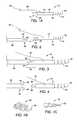
- FIG. 1Ais a side view of an embodiment of an attachment device in accordance with the present invention.
- FIGS. 1B and 1Care partial views of embodiments of tissue attachment portions
- FIG. 2is a side view of an embodiment of an attachment device and a stylet
- FIG. 3is a side view of the attachment device and the stylet shown in FIG. 2 in a connected position;
- FIG. 4is a side view of an embodiment of an attachment device and a stylet
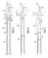
- FIG. 5is a side sectional view of an embodiment of an attachment system
- FIG. 6is a side sectional view of the attachment system shown in FIG. 5 with the outer sheath withdrawn;
- FIG. 7is a side sectional view of the attachment system shown in FIG. 6 with the inner sheath withdrawn;
- FIG. 8illustrates insertion of an embodiment of the attachment device into a tissue
- FIG. 9insertion of an embodiment of the attachment device into a tissue
- FIG. 10illustrates an embodiment of a suture lock system and an embodiment of the attachment device
- FIG. 11illustrates an embodiment of a suture lock system and an embodiment of the attachment device
- FIG. 12illustrates an embodiment of the suture lock system secured to an embodiment of the attachment device
- FIG. 13is a partial side view of an embodiment of an attachment device.
- FIGS. 14A and 14Billustrate embodiments of attachment devices including a suture.
- proximal and distalshould be understood as being in the terms of a physician delivering the expandable biopsy device to a patient.
- distalmeans the portion of the attachment device that is farthest from the physician and the term “proximal” means the portion of the attachment device that is nearest to the physician.
- FIG. 1Aillustrates an embodiment of an attachment device 10 in accordance with the present invention.
- the attachment device 10includes a body 12 having a proximal portion 14 and a distal portion 16 .
- a tissue attachment portion 18is operably connected to the distal portion 16 of the body 12 .
- the tissue attachment portion 18is a helical member having a sharp distal end 20 for piercing a patient's tissue.
- the tissue attachment portion 18may be a flattened spiral as shown in FIG. 1B or a threaded screw as shown in FIG. 10 to help hold the attachment device 18 in the tissue.
- Other configurations for the tissue attachment portion 18are also possible.
- the tissue attachment portion 18may be formed from a biocompatible material such as a metal or plastic and is configured to be rigid and to retain its shape from delivery through implantation into the patient's tissue. In some embodiments, the tissue attachment portion 18 is configured to be rotated about 4-5 rotations of the device 10 to insert into the tissue and may be removable from the tissue by the same number of rotations. In some embodiments, the tissue attachment portion 18 may be about 0.5 cm to about 2 cm in length, and in some embodiments, about 1 cm in length. In some embodiments, the attachment portion 18 may be formed from a wire having about a 0.01-0.04 inch O.D. and in some embodiments a wire having about a 0.02 inch O.D.
- the attachment device 10further includes a suture 22 having a distal portion 24 operably connected to the body 12 and a free end 25 .
- the proximal portion 14 of the body 12includes a first retainer 26 .
- the first retainer 26is configured to mate with a second retainer 32 provided on a distal portion 34 of a stylet 36 as shown in FIG. 2 .
- the first retainer 26 and second retainer 32have complimentary shapes that mate together to hold the attachment device 10 to the stylet 36 as described in more detail below.
- the first retainer 26 and the second retainer 32have a half cylinder shape, each with a flattened portion 33 , 35 that mate together.
- the first retainer 26 and the second retainer 32may have any complimentary shape.
- first retainer 26is a protrusion 42 that mates with the second retainer 32 that includes a recess 44 .
- the recess 44includes a pair of expandable arms 46 that enclose the protrusion 42 to hold the attachment device 10 to the stylet 36 .
- the attachment device 10 and the stylet 36are mated together with the complimentary retainers 26 , 32 joined.
- outer diameters of the stylet 36 , a connection region 40 and attachment device 10are substantially the same.
- the embodiment shown in FIG. 4may also be joined so that when the complimentary retainers 26 , 32 are joined, the arms 46 of the second retainer 32 fold in around the protrusion 42 of the first retainer so that the outer diameters of the stylet 36 , the connection region 40 and attachment device 10 are substantially the same.
- FIG. 5illustrates an embodiment of a delivery system 100 that may be used to deliver the attachment device 10 to the tissue site.
- the same type of system 100may also be used to remove the attachment device from the tissue site as discussed in more detail below.
- the attachment device 10is removably joined to the stylet 36 by joining the first and second retainers 26 , 32 together.
- An inner sheath 50is slidably positioned so that a distal end 52 of the inner sheath 50 is positioned over and distal to the joined first and second retainers 26 , 32 .
- An inner diameter 54 of the sheath 50is sized to fit over the first and second retainers 26 , 32 and hold the first and second retainers 26 , 32 in the joined position. Without the sheath 50 extending over the first and second retainers 26 , 32 , the first and second retainers 26 , 32 are easily separable.
- An outer sheath 60is slidably positioned over the inner sheath 50 and is distally extendable so that a distal end 62 of the outer sheath 60 extends distal to the distal end 20 of the attachment device 10 as shown in FIG. 5 .
- the outer sheath 60may be used to deliver the attachment device 10 to a treatment site so that the distal end 20 is not exposed while the device 10 is being guided through a patient's lumen. Once the device 10 is near the tissue site having the perforation to be joined, the outer sheath 60 may be withdrawn to expose the distal end 20 of the attachment device 10 .
- FIGS. 6 and 7illustrate delivery of the attachment device 10 to a tissue 11 .
- the outer sheath 60is proximally withdrawn so that the distal end 20 of the attachment device 10 is exposed.
- the distal end 20may include a sharp tip to facilitate entry of the tissue attachment portion 18 into the tissue 11 .
- the stylet 36may be rotated in an insertion direction 62 using a handle (not shown) so that the attachment device 10 also rotates and the tissue attachment portion 18 is rotatably inserted into the tissue 11 .
- the inner sheath 50is positioned over the first and second retainers 26 , 32 to maintain the connection between the first and second retainers 26 , 32 while the tissue attachment portion 18 is rotatably inserted so that the body 12 moves with the stylet 36 . If the position of the tissue attachment portion 18 is incorrect, the stylet 36 may be rotated in the opposite direction to the insertion direction 62 to withdraw the tissue attachment portion 18 from the tissue 11 . The tissue attachment portion 18 may then be reinserted in another position. The physician will know the length of the attachment portion 18 so that the depth that the attachment portion 18 is inserted into the tissue is controlled.
- the inner sheath 50may be proximally withdrawn to release the mating connection between the first and second retainers 26 , 32 as shown in FIG. 7 .
- the attachment device 10is released from the stylet 36 .
- the stylet 36 , the inner sheath 50 and the outer sheath 60may be proximally withdrawn from the patient.
- the free end 25 of the suture 22may extend proximally and external to the patient so that the physician may access the free end 25 to facilitate connecting the suture 22 of one attachment device 10 to the sutures 22 of one or more additional attachment devices 10 as described in detail below.
- the suture 22may be pulled proximally to retract the tissue into which the device 10 is inserted.
- the helical shape of the attachment portion 18may be used to retract the tissue using greater force than can be used with a straight device.
- FIG. 8illustrates a first attachment device 10 a positioned in the tissue 11 a so that the tissue attachment portion 18 is implanted into the tissue 11 and at least a portion of the body 12 and the suture 22 extend above the tissue 11 .
- a perforation 13is shown between the tissues 11 a and 11 b .
- a second attachment device 10 bis shown in FIG. 8 being positioned into the tissue 11 b .
- the stylet 36is being rotated in the insertion direction 62 so that the distal end 20 of the tissue attachment portion is rotatably inserted into the tissue 11 b.
- FIG. 9illustrates to attachment devices 10 a , 10 b positioned in tissue 11 a , 11 b on opposite sides of the perforation 13 .
- the delivery system 100has been withdrawn so that only the attachment devices 10 a , 10 b remain in the patient.
- the sutures 22have free ends 25 that extend proximally so that the sutures 22 and thus the attachment devices 10 a , 10 b can be easily joined to approximate the tissues 11 a , 11 b and close the perforation 13 .
- FIG. 10illustrates an embodiment of a suture lock system 120 that may be employed to join the attachment devices 10 a , 10 b together to approximate the tissues 11 a , 11 b and close the perforation 13 .
- the suture lock system 120includes a suture lock 121 having a sleeve 126 and a locking body 140 .
- the suture lock system 120includes an outer catheter 124 that includes the sleeve 126 positioned at a distal end 128 of the outer catheter 124 .
- the sleeve 126may include a shoulder 130 that abuts the distal end 128 so the outer catheter 126 can push the sleeve 126 into position as described below.
- the sleeve 126may include a cavity 131 that is sized and shaped to accommodate a plurality of attachment devices 10 .
- the cavity 131may accommodate 1, 2, 3, 4 or more attachment devices 10 .
- the outer catheter 124includes a lumen 132 extending at least partially therethrough.
- the sleeve 126is positioned at least partially within the lumen 132 and is releasable from the outer catheter 124 .
- the sleeve 126includes a lumen 134 extending therethrough.
- the suture lock system 120further includes the locking body 140 that is sized and shaped to at least partially fit with in the lumen 134 of the sleeve 126 and to secure one or more sutures 22 extending through the lumen 134 .
- the locking body 140may include a shoulder 142 as shown in FIG. 10 .
- the suture lock system 120may also include an inner catheter 150 that is sized to coaxially extend within the lumen 132 of the outer catheter 124 .
- the inner catheter 150includes a distal end 152 that may abut the shoulder 142 of the locking body 140 so the inner catheter 150 may advance the locking body 140 to a locked position as described below.
- FIG. 11illustrates the tissue 11 a , 11 b having been approximated by pulling the sutures 22 to join the tissue 11 a , 11 b together to close the perforation 13 .
- the outer catheter 124has been proximally withdrawn and the sleeve 126 released from the outer catheter 124 .
- the sleeve 126is shown with the shoulder 130 positioned against the tissue 11 a , 11 b and with the attachment devices 10 a , 10 b positioned within the cavity 131 of the sleeve 126 .
- the sutures 22extend through the lumen 134 of the sleeve 126 and into the lumen 132 of the outer catheter 124 .
- the inner catheter 150is advanceable within the outer catheter 124 to move the locking body 140 to a locked configuration 170 shown in FIG. 12 .
- the locked configuration 170the plurality of sutures 22 are secured between a wall 127 the sleeve 126 and the locking body 140 so that the sutures 22 may be tensioned to maintain the position of the tissue 11 a , 11 b .
- the attachment devices 10 a , 10 bare held within the cavity 131 of the sleeve 126 with the tissue attachment portions 18 secured within the tissue 11 a , 11 b and the tissue 11 a , 11 b approximated.
- the attachment devices 10 a , 10 bremain locked in position so that the perforation can heal. Once the perforation is healed, the attachment devices 10 a , 10 b , the sleeve 126 and locking body 140 will eventually slough off and pass naturally.
- FIG. 13illustrates an embodiment of an attachment device 210 in accordance with the present invention.
- the attachment device 210includes a tissue attachment portion 212 having a proximal portion 214 and a distal portion 216 .
- the tissue attachment portion 212is a helical member having a sharp distal end 220 for piercing a patient's tissue and may be similar to the tissue attachment portion 18 described above.
- the attachment device 210may be delivered to the site and rotationally inserted using a torque cable 226 operably connected to the attachment device 210 .
- the attachment device 210may be delivered to the site within an outer sheath 228 so that the attachment portion 212 or the distal tip 220 does not contact an accessory channel of a delivery device such as an endoscope or a patient's tissue until the attachment device 210 is at the proper position.
- a delivery devicesuch as an endoscope or a patient's tissue
- the attachment device 210further includes a suture 222 operably connected to the proximal portion 214 of the device 210 as shown in FIG. 14A .
- the attachment device 210may include a loop 230 at the proximal portion 214 .
- the suture 222may be threaded through the loop 230 .
- the suture 222may be used to join the device 210 to other attachment devices 210 or to retract the tissue to which the device 210 is inserted.
- a plurality of devices 210may be positioned in adjacent tissue sites similar to the devices 10 described above to approximate tissue portions and may be secured using a suture lock as described above.
- the closuremay be a purse string closure with multiple devices 210 being pulled together using the sutures 222 .
- the attachment devices described hereinmay also be removed from the tissue site using a device like the delivery system described above.
- the removal of the attachment device 10will be described with respect to the delivery system 100 and FIGS. 5-7 .
- the suture 22may be cut using a cutting device before removal of each attachment device 10 .
- the insertion method shown in FIGS. 5-7may be reversed.
- the stylet 36is extended from the inner sheath 50 and the outer sheath 60 and the first and second retainers 26 , 32 are aligned as shown in FIG. 7 .
- the stylet 36is advanced toward the attachment device 10 so the attachment device 10 is joined to the stylet 36 and the first and second retainers 26 , 32 are joined.
- the inner sheath 50is advanced toward the tissue until the first and second retainers 26 , 32 that are rejoined are covered by a portion of the inner sheath 50 as shown in FIG. 6 .
- the stylet 36may be rotated in a direction opposite the insertion direction 62 using a handle (not shown) so that the attachment device 10 also rotates and the tissue attachment portion 18 is rotatably removed from the tissue 11 .
- the inner sheath 50is positioned over the first and second retainers 26 , 32 to maintain the connection between the first and second retainers 26 , 32 while the tissue attachment portion 18 is rotatably removed so that the body 12 moves with the stylet 36 .
- the outer sheath 60may be advanced over the inner sheath 50 and the tissue attachment portion 18 to cover the distal end 20 of the attachment device 10 as shown in FIG. 5 .
- the outer sheath 60may be used to remove the attachment device 10 from the patient so that the distal end 20 is not exposed while the device 10 is being guided through a patient's lumen.
- the materials used to form the attachment devices described herein and the suture lockmay be any biocompatible materials suitable for implantation in a bodily lumen.
- the tissue attachment portionmay be made from any suitable biocompatible metal, such as stainless steel and shape memory alloys, such as nitinol or plastic that are sufficiently rigid to maintain the shape the tissue attachment portion throughout the procedure.
- the tissue attachment portionis not intended to change shape once the portion is inserted into the tissue.
- the body, the sleeve and the locking bodymay be formed from any suitable material such as stainless steel, titanium, nitinol or other metals/alloys as well as various ceramics and plastic materials, such as polycarbonates, polyamides including nylon, polytertrafluorethylenes (i.e.
- the suturesmay be made from common suture material as known in the art, for example polyester suture such as 4-0 Tevdek®, nylon, silk, polypropylene, ultra high molecular weight polyethylene (UHMPE) and the like.
- the suturesmay be monofilament, braided, twisted or multifilament.
Landscapes
- Health & Medical Sciences (AREA)
- Surgery (AREA)
- Life Sciences & Earth Sciences (AREA)
- Medical Informatics (AREA)
- Nuclear Medicine, Radiotherapy & Molecular Imaging (AREA)
- Engineering & Computer Science (AREA)
- Biomedical Technology (AREA)
- Heart & Thoracic Surgery (AREA)
- Molecular Biology (AREA)
- Animal Behavior & Ethology (AREA)
- General Health & Medical Sciences (AREA)
- Public Health (AREA)
- Veterinary Medicine (AREA)
- Rheumatology (AREA)
- Cardiology (AREA)
- Surgical Instruments (AREA)
Abstract
Description
Claims (7)
Priority Applications (1)
| Application Number | Priority Date | Filing Date | Title |
|---|---|---|---|
| US13/733,420US9107654B2 (en) | 2012-01-05 | 2013-01-03 | Attachment device for tissue approximation and retraction |
Applications Claiming Priority (2)
| Application Number | Priority Date | Filing Date | Title |
|---|---|---|---|
| US201261583409P | 2012-01-05 | 2012-01-05 | |
| US13/733,420US9107654B2 (en) | 2012-01-05 | 2013-01-03 | Attachment device for tissue approximation and retraction |
Publications (2)
| Publication Number | Publication Date |
|---|---|
| US20130178899A1 US20130178899A1 (en) | 2013-07-11 |
| US9107654B2true US9107654B2 (en) | 2015-08-18 |
Family
ID=47604170
Family Applications (1)
| Application Number | Title | Priority Date | Filing Date |
|---|---|---|---|
| US13/733,420Active2033-09-16US9107654B2 (en) | 2012-01-05 | 2013-01-03 | Attachment device for tissue approximation and retraction |
Country Status (2)
| Country | Link |
|---|---|
| US (1) | US9107654B2 (en) |
| WO (1) | WO2013103796A1 (en) |
Cited By (6)
| Publication number | Priority date | Publication date | Assignee | Title |
|---|---|---|---|---|
| EP2128260A2 (en) | 1998-10-07 | 2009-12-02 | STRYKER CORPORATION (a Michigan corporation) | Modified TGF-beta superfamily proteins |
| WO2017209519A1 (en) | 2016-05-31 | 2017-12-07 | Mogam Institute For Biomedical Research | Ab6 family designer ligands of tgf-beta superfamily |
| US20200178956A1 (en)* | 2018-12-05 | 2020-06-11 | Apollo Endosurgery Us, Inc. | Endoscopic tissue approximation system and methods |
| US20210212687A1 (en)* | 2020-01-13 | 2021-07-15 | Brian Lim | Gastrointestinal tissue approximation clip (gi tac) system |
| US20210386425A1 (en)* | 2020-01-13 | 2021-12-16 | Brian Lim | Gastrointestinal tissue approximation clip (gi tac) system |
| US12035904B2 (en) | 2020-03-03 | 2024-07-16 | Boston Scientific Scimed, Inc. | Endoscopic tissue approximation system and methods |
Families Citing this family (4)
| Publication number | Priority date | Publication date | Assignee | Title |
|---|---|---|---|---|
| US9554836B2 (en)* | 2012-06-29 | 2017-01-31 | The Cleveland Clinic Foundation | Intramedullary bone stent |
| US10786235B2 (en) | 2012-10-31 | 2020-09-29 | Anchor Innovation Medical, Inc. | Method and apparatus for closing a fissure in the annulus of an intervertebral disc, and/or for effecting other anatomical repairs and/or fixations |
| US9433404B2 (en)* | 2012-10-31 | 2016-09-06 | Suture Concepts Inc. | Method and apparatus for closing fissures in the annulus fibrosus |
| CA2920546A1 (en) | 2013-08-16 | 2015-02-19 | Suture Concepts Inc. | Method and apparatus for closing a fissure in the annulus of an intervertebral disc, and/or for effecting other anatomical repairs and/or fixations |
Citations (44)
| Publication number | Priority date | Publication date | Assignee | Title |
|---|---|---|---|---|
| US4632100A (en)* | 1985-08-29 | 1986-12-30 | Marlowe E. Goble | Suture anchor assembly |
| US5217486A (en)* | 1992-02-18 | 1993-06-08 | Mitek Surgical Products, Inc. | Suture anchor and installation tool |
| US5246014A (en) | 1991-11-08 | 1993-09-21 | Medtronic, Inc. | Implantable lead system |
| US5304195A (en)* | 1991-12-12 | 1994-04-19 | Target Therapeutics, Inc. | Detachable pusher-vasoocclusive coil assembly with interlocking coupling |
| US5324308A (en)* | 1993-10-28 | 1994-06-28 | Javin Pierce | Suture anchor |
| US5330503A (en) | 1989-05-16 | 1994-07-19 | Inbae Yoon | Spiral suture needle for joining tissue |
| US5443482A (en)* | 1993-06-23 | 1995-08-22 | Kevin R. Stone | Suture anchor assembly |
| US5458608A (en)* | 1993-06-03 | 1995-10-17 | Surgin Surgical Instrumentation Inc. | Laparoscopic instruments and methods |
| US5573548A (en)* | 1994-06-09 | 1996-11-12 | Zimmer, Inc. | Suture anchor |
| US5582616A (en) | 1994-08-05 | 1996-12-10 | Origin Medsystems, Inc. | Surgical helical fastener with applicator |
| US5584835A (en)* | 1993-10-18 | 1996-12-17 | Greenfield; Jon B. | Soft tissue to bone fixation device and method |
| US5591207A (en)* | 1995-03-30 | 1997-01-07 | Linvatec Corporation | Driving system for inserting threaded suture anchors |
| US5607432A (en)* | 1995-01-23 | 1997-03-04 | Linvatec Corporation | Threaded suture anchor retriever |
| US5626613A (en) | 1995-05-04 | 1997-05-06 | Arthrex, Inc. | Corkscrew suture anchor and driver |
| US5626614A (en) | 1995-12-22 | 1997-05-06 | Applied Medical Resources Corporation | T-anchor suturing device and method for using same |
| US5662683A (en) | 1995-08-22 | 1997-09-02 | Ortho Helix Limited | Open helical organic tissue anchor and method of facilitating healing |
| US5665111A (en)* | 1996-01-22 | 1997-09-09 | Raymedica, Inc. | Method for anchoring a surgical suture to bone |
| US5728116A (en) | 1994-01-13 | 1998-03-17 | Ethicon, Inc. | Spiral surgical tack |
| US5810851A (en) | 1996-03-05 | 1998-09-22 | Yoon; Inbae | Suture spring device |
| US5843127A (en)* | 1994-08-22 | 1998-12-01 | Le Medical Technologies, Inc. | Fixation device and method for installing same |
| US5988171A (en) | 1997-06-26 | 1999-11-23 | Influence Medical Technologies, Ltd. | Methods and devices for the treatment of airway obstruction, sleep apnea and snoring |
| US6045573A (en)* | 1999-01-21 | 2000-04-04 | Ethicon, Inc. | Suture anchor having multiple sutures |
| US6171320B1 (en) | 1996-12-25 | 2001-01-09 | Niti Alloys Technologies Ltd. | Surgical clip |
| US20020120292A1 (en)* | 2001-02-28 | 2002-08-29 | Morgan Daniel E. | Parabolic eyelet suture anchor |
| US20030014127A1 (en) | 1988-11-10 | 2003-01-16 | Martti Talja | Biodegradable surgical implants and devices |
| US20030130669A1 (en)* | 2002-01-10 | 2003-07-10 | Damarati John Jairo | Method and device for endoscopic suturing |
| US20050090861A1 (en) | 2003-10-27 | 2005-04-28 | Scimed Life Systems, Inc. | Vaso-occlusive devices with in-situ stiffening elements |
| US6960217B2 (en) | 2001-11-28 | 2005-11-01 | Aptus Endosystems, Inc. | Endovascular aneurysm repair system |
| US6986776B2 (en) | 2001-06-28 | 2006-01-17 | Craig H Randall | Suturing apparatus, method and system |
| US20060135971A1 (en) | 2004-05-07 | 2006-06-22 | Usgi Medical Inc. | System for treating gastroesophageal reflux disease |
| EP1759663A2 (en) | 2005-08-30 | 2007-03-07 | St. Jude Medical, Inc. | Soft body tissue remodeling methods and apparatus |
| WO2007076018A2 (en) | 2005-12-22 | 2007-07-05 | Kfx Medical Corporation | System and method for attaching soft tissue to bone |
| US20070198050A1 (en)* | 2006-02-22 | 2007-08-23 | Phase One Medica, Llc | Medical implant device |
| US20070282355A1 (en) | 2006-06-01 | 2007-12-06 | Wilson-Cook Medical Inc. | Release mechanisms for a clip device |
| US7306614B2 (en) | 2001-05-30 | 2007-12-11 | Satiety, Inc. | Overtube apparatus for insertion into a body |
| US20080045982A1 (en) | 2003-12-19 | 2008-02-21 | John To | Devices and methods for anchoring tissue |
| US20080045976A1 (en) | 2006-08-16 | 2008-02-21 | Wilson-Cook Medical Inc. | Suturing device |
| US7431725B2 (en) | 2003-10-10 | 2008-10-07 | Synecor, Llc | Devices and methods for retaining a gastro-esophageal implant |
| US20080300629A1 (en) | 2007-05-31 | 2008-12-04 | Wilson-Cook Medical Inc. | Suture lock |
| US20090069847A1 (en) | 2007-08-17 | 2009-03-12 | Wilson-Cook Medical Inc. | Suture lock |
| US20090240326A1 (en)* | 2005-10-26 | 2009-09-24 | Cardiosolutions | Implant Delivery and Deployment System and Method |
| US20090275971A1 (en) | 2007-10-30 | 2009-11-05 | Boston Scientific Scimed, Inc. | Energy activated preloaded detachment mechanisms for implantable devices |
| US20100145385A1 (en) | 2008-12-05 | 2010-06-10 | Wilson-Cook Medical, Inc. | Tissue anchors for purse-string closure of perforations |
| WO2010128502A1 (en) | 2009-05-04 | 2010-11-11 | Valtech Cardio, Ltd. | Implantation of repair chords in the heart |
- 2013
- 2013-01-03USUS13/733,420patent/US9107654B2/enactiveActive
- 2013-01-04WOPCT/US2013/020258patent/WO2013103796A1/enactiveApplication Filing
Patent Citations (46)
| Publication number | Priority date | Publication date | Assignee | Title |
|---|---|---|---|---|
| US4632100A (en)* | 1985-08-29 | 1986-12-30 | Marlowe E. Goble | Suture anchor assembly |
| US20030014127A1 (en) | 1988-11-10 | 2003-01-16 | Martti Talja | Biodegradable surgical implants and devices |
| US5330503A (en) | 1989-05-16 | 1994-07-19 | Inbae Yoon | Spiral suture needle for joining tissue |
| US5246014A (en) | 1991-11-08 | 1993-09-21 | Medtronic, Inc. | Implantable lead system |
| US5304195A (en)* | 1991-12-12 | 1994-04-19 | Target Therapeutics, Inc. | Detachable pusher-vasoocclusive coil assembly with interlocking coupling |
| US5217486A (en)* | 1992-02-18 | 1993-06-08 | Mitek Surgical Products, Inc. | Suture anchor and installation tool |
| US5458608A (en)* | 1993-06-03 | 1995-10-17 | Surgin Surgical Instrumentation Inc. | Laparoscopic instruments and methods |
| US5443482A (en)* | 1993-06-23 | 1995-08-22 | Kevin R. Stone | Suture anchor assembly |
| US5584835A (en)* | 1993-10-18 | 1996-12-17 | Greenfield; Jon B. | Soft tissue to bone fixation device and method |
| US5324308A (en)* | 1993-10-28 | 1994-06-28 | Javin Pierce | Suture anchor |
| US5728116A (en) | 1994-01-13 | 1998-03-17 | Ethicon, Inc. | Spiral surgical tack |
| US5573548A (en)* | 1994-06-09 | 1996-11-12 | Zimmer, Inc. | Suture anchor |
| US5582616A (en) | 1994-08-05 | 1996-12-10 | Origin Medsystems, Inc. | Surgical helical fastener with applicator |
| US6884248B2 (en) | 1994-08-05 | 2005-04-26 | Sherwood Services Ag | Surgical helical fastener with applicator |
| US5810882A (en) | 1994-08-05 | 1998-09-22 | Origin Medsystems, Inc. | Surgical helical fastener with applicator and method of use |
| US5843127A (en)* | 1994-08-22 | 1998-12-01 | Le Medical Technologies, Inc. | Fixation device and method for installing same |
| US5607432A (en)* | 1995-01-23 | 1997-03-04 | Linvatec Corporation | Threaded suture anchor retriever |
| US5591207A (en)* | 1995-03-30 | 1997-01-07 | Linvatec Corporation | Driving system for inserting threaded suture anchors |
| US5626613A (en) | 1995-05-04 | 1997-05-06 | Arthrex, Inc. | Corkscrew suture anchor and driver |
| US5662683A (en) | 1995-08-22 | 1997-09-02 | Ortho Helix Limited | Open helical organic tissue anchor and method of facilitating healing |
| US5626614A (en) | 1995-12-22 | 1997-05-06 | Applied Medical Resources Corporation | T-anchor suturing device and method for using same |
| US5665111A (en)* | 1996-01-22 | 1997-09-09 | Raymedica, Inc. | Method for anchoring a surgical suture to bone |
| US5810851A (en) | 1996-03-05 | 1998-09-22 | Yoon; Inbae | Suture spring device |
| US6171320B1 (en) | 1996-12-25 | 2001-01-09 | Niti Alloys Technologies Ltd. | Surgical clip |
| US5988171A (en) | 1997-06-26 | 1999-11-23 | Influence Medical Technologies, Ltd. | Methods and devices for the treatment of airway obstruction, sleep apnea and snoring |
| US6045573A (en)* | 1999-01-21 | 2000-04-04 | Ethicon, Inc. | Suture anchor having multiple sutures |
| US20020120292A1 (en)* | 2001-02-28 | 2002-08-29 | Morgan Daniel E. | Parabolic eyelet suture anchor |
| US7306614B2 (en) | 2001-05-30 | 2007-12-11 | Satiety, Inc. | Overtube apparatus for insertion into a body |
| US6986776B2 (en) | 2001-06-28 | 2006-01-17 | Craig H Randall | Suturing apparatus, method and system |
| US6960217B2 (en) | 2001-11-28 | 2005-11-01 | Aptus Endosystems, Inc. | Endovascular aneurysm repair system |
| US20030130669A1 (en)* | 2002-01-10 | 2003-07-10 | Damarati John Jairo | Method and device for endoscopic suturing |
| US7431725B2 (en) | 2003-10-10 | 2008-10-07 | Synecor, Llc | Devices and methods for retaining a gastro-esophageal implant |
| US20050090861A1 (en) | 2003-10-27 | 2005-04-28 | Scimed Life Systems, Inc. | Vaso-occlusive devices with in-situ stiffening elements |
| US20080045982A1 (en) | 2003-12-19 | 2008-02-21 | John To | Devices and methods for anchoring tissue |
| US20060135971A1 (en) | 2004-05-07 | 2006-06-22 | Usgi Medical Inc. | System for treating gastroesophageal reflux disease |
| EP1759663A2 (en) | 2005-08-30 | 2007-03-07 | St. Jude Medical, Inc. | Soft body tissue remodeling methods and apparatus |
| US20090240326A1 (en)* | 2005-10-26 | 2009-09-24 | Cardiosolutions | Implant Delivery and Deployment System and Method |
| WO2007076018A2 (en) | 2005-12-22 | 2007-07-05 | Kfx Medical Corporation | System and method for attaching soft tissue to bone |
| US20070198050A1 (en)* | 2006-02-22 | 2007-08-23 | Phase One Medica, Llc | Medical implant device |
| US20070282355A1 (en) | 2006-06-01 | 2007-12-06 | Wilson-Cook Medical Inc. | Release mechanisms for a clip device |
| US20080045976A1 (en) | 2006-08-16 | 2008-02-21 | Wilson-Cook Medical Inc. | Suturing device |
| US20080300629A1 (en) | 2007-05-31 | 2008-12-04 | Wilson-Cook Medical Inc. | Suture lock |
| US20090069847A1 (en) | 2007-08-17 | 2009-03-12 | Wilson-Cook Medical Inc. | Suture lock |
| US20090275971A1 (en) | 2007-10-30 | 2009-11-05 | Boston Scientific Scimed, Inc. | Energy activated preloaded detachment mechanisms for implantable devices |
| US20100145385A1 (en) | 2008-12-05 | 2010-06-10 | Wilson-Cook Medical, Inc. | Tissue anchors for purse-string closure of perforations |
| WO2010128502A1 (en) | 2009-05-04 | 2010-11-11 | Valtech Cardio, Ltd. | Implantation of repair chords in the heart |
Non-Patent Citations (2)
| Title |
|---|
| International Search Report mailed Apr. 25, 2013 for International Application No. PCT/US2013/020258. |
| Written Opinion of the International Searching Authority mailed Apr. 25, 2013 for International Application No. PCT/US2013/020258. |
Cited By (10)
| Publication number | Priority date | Publication date | Assignee | Title |
|---|---|---|---|---|
| EP2128260A2 (en) | 1998-10-07 | 2009-12-02 | STRYKER CORPORATION (a Michigan corporation) | Modified TGF-beta superfamily proteins |
| WO2017209519A1 (en) | 2016-05-31 | 2017-12-07 | Mogam Institute For Biomedical Research | Ab6 family designer ligands of tgf-beta superfamily |
| US20200178956A1 (en)* | 2018-12-05 | 2020-06-11 | Apollo Endosurgery Us, Inc. | Endoscopic tissue approximation system and methods |
| US11864751B2 (en)* | 2018-12-05 | 2024-01-09 | Boston Scientific Scimed, Inc. | Endoscopic tissue approximation system and methods |
| US12376847B2 (en) | 2018-12-05 | 2025-08-05 | Boston Scientific Scimed, Inc. | Endoscopic tissue approximation system and methods |
| US20210212687A1 (en)* | 2020-01-13 | 2021-07-15 | Brian Lim | Gastrointestinal tissue approximation clip (gi tac) system |
| US20210386425A1 (en)* | 2020-01-13 | 2021-12-16 | Brian Lim | Gastrointestinal tissue approximation clip (gi tac) system |
| US11998205B2 (en)* | 2020-01-13 | 2024-06-04 | Brian Lim | Gastrointestinal tissue approximation clip (GI TAC) system |
| US12064114B2 (en)* | 2020-01-13 | 2024-08-20 | Brian Lim | Gastrointestinal tissue approximation clip (GI TAC) system |
| US12035904B2 (en) | 2020-03-03 | 2024-07-16 | Boston Scientific Scimed, Inc. | Endoscopic tissue approximation system and methods |
Also Published As
| Publication number | Publication date |
|---|---|
| WO2013103796A1 (en) | 2013-07-11 |
| US20130178899A1 (en) | 2013-07-11 |
Similar Documents
| Publication | Publication Date | Title |
|---|---|---|
| US9107654B2 (en) | Attachment device for tissue approximation and retraction | |
| US12376847B2 (en) | Endoscopic tissue approximation system and methods | |
| US12383707B2 (en) | Anchor instrumentation and methods | |
| US8382776B2 (en) | Medical devices, systems and methods for rapid deployment and fixation of tissue anchors | |
| US8475476B2 (en) | System and method for accessing a body cavity | |
| US8480686B2 (en) | Methods and devices for delivering and applying suture anchors | |
| TW201225997A (en) | Assembly and method for stabilizing a percutaneous cable | |
| CN103037778A (en) | tissue retractor assembly | |
| CN106714704A (en) | Systems and methods for helically advancing suture in tissue | |
| US12035904B2 (en) | Endoscopic tissue approximation system and methods | |
| US12167844B2 (en) | Endoscopic tissue approximation system and methods | |
| US20160007993A1 (en) | Revolving approximation device | |
| WO2010077608A1 (en) | Apparatus and methods for controlled release of tacking devices | |
| US20110264117A1 (en) | Tissue joining device and instrument for enabling use of a tissue joining device | |
| JP2025523926A (en) | Minimally Invasive Endoscopic Suturing Device |
Legal Events
| Date | Code | Title | Description |
|---|---|---|---|
| AS | Assignment | Owner name:COOK MEDICAL TECHNOLOGIES LLC, INDIANA Free format text:ASSIGNMENT OF ASSIGNORS INTEREST;ASSIGNOR:CHANG, KENNETH J.;REEL/FRAME:029712/0890 Effective date:20130103 Owner name:WILSON-COOK MEDICAL INC., NORTH CAROLINA Free format text:ASSIGNMENT OF ASSIGNORS INTEREST;ASSIGNORS:CHMURA, KEVIN;DUCHARME, RICHARD W.;MCLAWHORN, TYLER E.;SIGNING DATES FROM 20121214 TO 20121217;REEL/FRAME:029712/0907 Owner name:COOK MEDICAL TECHNOLOGIES LLC, INDIANA Free format text:ASSIGNMENT OF ASSIGNORS INTEREST;ASSIGNOR:WILSON-COOK MEDICAL INC.;REEL/FRAME:029716/0134 Effective date:20121219 | |
| STCF | Information on status: patent grant | Free format text:PATENTED CASE | |
| MAFP | Maintenance fee payment | Free format text:PAYMENT OF MAINTENANCE FEE, 4TH YEAR, LARGE ENTITY (ORIGINAL EVENT CODE: M1551); ENTITY STATUS OF PATENT OWNER: LARGE ENTITY Year of fee payment:4 | |
| MAFP | Maintenance fee payment | Free format text:PAYMENT OF MAINTENANCE FEE, 8TH YEAR, LARGE ENTITY (ORIGINAL EVENT CODE: M1552); ENTITY STATUS OF PATENT OWNER: LARGE ENTITY Year of fee payment:8 | |
| AS | Assignment | Owner name:WILMINGTON TRUST, NATIONAL ASSOCIATION, AS COLLATERAL AGENT, DELAWARE Free format text:SECURITY INTEREST;ASSIGNOR:COOK MEDICAL TECHNOLOGIES LLC;REEL/FRAME:066700/0277 Effective date:20240227 |