US9105380B2 - Magnetic attachment system - Google Patents
Magnetic attachment systemDownload PDFInfo
- Publication number
- US9105380B2 US9105380B2US14/198,191US201414198191AUS9105380B2US 9105380 B2US9105380 B2US 9105380B2US 201414198191 AUS201414198191 AUS 201414198191AUS 9105380 B2US9105380 B2US 9105380B2
- Authority
- US
- United States
- Prior art keywords
- magnetic
- code
- attachment system
- component
- magnetic attachment
- Prior art date
- Legal status (The legal status is an assumption and is not a legal conclusion. Google has not performed a legal analysis and makes no representation as to the accuracy of the status listed.)
- Expired - Fee Related
Links
Images


Classifications
- H—ELECTRICITY
- H01—ELECTRIC ELEMENTS
- H01F—MAGNETS; INDUCTANCES; TRANSFORMERS; SELECTION OF MATERIALS FOR THEIR MAGNETIC PROPERTIES
- H01F7/00—Magnets
- A—HUMAN NECESSITIES
- A41—WEARING APPAREL
- A41F—GARMENT FASTENINGS; SUSPENDERS
- A41F1/00—Fastening devices specially adapted for garments
- A41F1/002—Magnetic fastening devices
- A—HUMAN NECESSITIES
- A45—HAND OR TRAVELLING ARTICLES
- A45C—PURSES; LUGGAGE; HAND CARRIED BAGS
- A45C13/00—Details; Accessories
- A45C13/10—Arrangement of fasteners
- A45C13/1069—Arrangement of fasteners magnetic
- A—HUMAN NECESSITIES
- A45—HAND OR TRAVELLING ARTICLES
- A45F—TRAVELLING OR CAMP EQUIPMENT: SACKS OR PACKS CARRIED ON THE BODY
- A45F5/00—Holders or carriers for hand articles; Holders or carriers for use while travelling or camping
- A45F5/02—Fastening articles to the garment
- A—HUMAN NECESSITIES
- A45—HAND OR TRAVELLING ARTICLES
- A45F—TRAVELLING OR CAMP EQUIPMENT: SACKS OR PACKS CARRIED ON THE BODY
- A45F5/00—Holders or carriers for hand articles; Holders or carriers for use while travelling or camping
- A45F5/02—Fastening articles to the garment
- A45F5/022—Fastening articles to the garment within pockets
- B—PERFORMING OPERATIONS; TRANSPORTING
- B42—BOOKBINDING; ALBUMS; FILES; SPECIAL PRINTED MATTER
- B42F—SHEETS TEMPORARILY ATTACHED TOGETHER; FILING APPLIANCES; FILE CARDS; INDEXING
- B42F1/00—Sheets temporarily attached together without perforating; Means therefor
- B—PERFORMING OPERATIONS; TRANSPORTING
- B42—BOOKBINDING; ALBUMS; FILES; SPECIAL PRINTED MATTER
- B42F—SHEETS TEMPORARILY ATTACHED TOGETHER; FILING APPLIANCES; FILE CARDS; INDEXING
- B42F1/00—Sheets temporarily attached together without perforating; Means therefor
- B42F1/02—Paper-clips or like fasteners
- B42F1/04—Paper-clips or like fasteners metallic
- B42F1/06—Paper-clips or like fasteners metallic of flat cross-section, e.g. made of a piece of metal sheet
- G—PHYSICS
- G09—EDUCATION; CRYPTOGRAPHY; DISPLAY; ADVERTISING; SEALS
- G09F—DISPLAYING; ADVERTISING; SIGNS; LABELS OR NAME-PLATES; SEALS
- G09F7/00—Signs, name or number plates, letters, numerals, or symbols; Panels or boards
- G09F7/02—Signs, plates, panels or boards using readily-detachable elements bearing or forming symbols
- G09F7/04—Signs, plates, panels or boards using readily-detachable elements bearing or forming symbols the elements being secured or adapted to be secured by magnetic means
- H—ELECTRICITY
- H01—ELECTRIC ELEMENTS
- H01F—MAGNETS; INDUCTANCES; TRANSFORMERS; SELECTION OF MATERIALS FOR THEIR MAGNETIC PROPERTIES
- H01F7/00—Magnets
- H01F7/02—Permanent magnets [PM]
- H01F7/0231—Magnetic circuits with PM for power or force generation
- H01F7/0242—Magnetic drives, magnetic coupling devices
- H—ELECTRICITY
- H01—ELECTRIC ELEMENTS
- H01F—MAGNETS; INDUCTANCES; TRANSFORMERS; SELECTION OF MATERIALS FOR THEIR MAGNETIC PROPERTIES
- H01F7/00—Magnets
- H01F7/02—Permanent magnets [PM]
- H01F7/0231—Magnetic circuits with PM for power or force generation
- H01F7/0252—PM holding devices
- H—ELECTRICITY
- H01—ELECTRIC ELEMENTS
- H01F—MAGNETS; INDUCTANCES; TRANSFORMERS; SELECTION OF MATERIALS FOR THEIR MAGNETIC PROPERTIES
- H01F7/00—Magnets
- H01F7/02—Permanent magnets [PM]
- H01F7/0231—Magnetic circuits with PM for power or force generation
- H01F7/0252—PM holding devices
- H01F7/0263—Closures, bags, bands, engagement devices with male and female parts
- H—ELECTRICITY
- H01—ELECTRIC ELEMENTS
- H01F—MAGNETS; INDUCTANCES; TRANSFORMERS; SELECTION OF MATERIALS FOR THEIR MAGNETIC PROPERTIES
- H01F7/00—Magnets
- H01F7/02—Permanent magnets [PM]
- H01F7/04—Means for releasing the attractive force
- A—HUMAN NECESSITIES
- A44—HABERDASHERY; JEWELLERY
- A44D—INDEXING SCHEME RELATING TO BUTTONS, PINS, BUCKLES OR SLIDE FASTENERS, AND TO JEWELLERY, BRACELETS OR OTHER PERSONAL ADORNMENTS
- A44D2203/00—Fastening by use of magnets
- Y—GENERAL TAGGING OF NEW TECHNOLOGICAL DEVELOPMENTS; GENERAL TAGGING OF CROSS-SECTIONAL TECHNOLOGIES SPANNING OVER SEVERAL SECTIONS OF THE IPC; TECHNICAL SUBJECTS COVERED BY FORMER USPC CROSS-REFERENCE ART COLLECTIONS [XRACs] AND DIGESTS
- Y10—TECHNICAL SUBJECTS COVERED BY FORMER USPC
- Y10T—TECHNICAL SUBJECTS COVERED BY FORMER US CLASSIFICATION
- Y10T24/00—Buckles, buttons, clasps, etc.
- Y10T24/32—Buckles, buttons, clasps, etc. having magnetic fastener
Definitions
- Ser. No. 12/952,391is also a continuation of application Ser. No. 12/478,969, titled “Coded Magnet Structures for Selective Association of Articles,” filed Jun. 5, 2009 by Fullerton et al., U.S. Pat. No. 7,843,297; Ser. No. 12/952,391 is also a continuation of application Ser. No. 12/479,013, titled “Magnetic Force Profile System Using Coded Magnet Structures,” filed Jun. 5, 2009 by Fullerton et al., U.S. Pat. No.
- the present inventionrelates generally to a system for magnetic attachment. More particularly, the present invention relates to a system for magnetic attachment involving a male component and female component each having complementary magnetic structures.
- a magnetic attachment systemincludes a female component associated with a first object, the female component including a hole and a first magnetic structure having a first plurality of magnetic source regions having a first polarity pattern, and a male component associated with a second object, the male component including a peg that can be inserted into the hole and a second magnetic structure having a second plurality of magnetic source regions having a second polarity pattern complementary to the first polarity pattern.
- the male component and the female componentare configured such that when the peg is inserted into the hole the first and second magnetic structures face each other across an interface boundary enabling magnetic attachment of the first object to the second object, where while the peg remains within said hole said male component can be rotated relative to the female component but translational movement of the male component relative to the female component is constrained, where the first polarity pattern and said second polarity pattern are in accordance with a cyclic implementation of a code of length N, and where said code has a cyclic correlation function having a single peak and a plurality of off peaks per code modulo.
- the first and second polarity patternscan be irregular polarity patterns.
- the first and second magnetic structurescan produce a peak attract force when in a complementary rotational alignment position that magnetically attaches the first object to the second object.
- the first and second magnetic structurescan produce an off-peak force that is an attract force less than the peak attract force when the male component has been rotated relative to the female component plus or minus 360/N degrees from the complementary rotational alignment position and said cyclic implementation of said code includes only one code modulo of said code.
- the first and second magnetic structurescan produce an off-peak force that is a substantially zero force when the male component has been rotated relative to the female component plus or minus 360/N degrees from the complementary rotational alignment position and said cyclic implementation of said code includes only one code modulo of said code.
- the first and second magnetic structurescan produce an off-peak force that is a repel force when the male component has been rotated relative to the female component plus or minus 360/N degrees from the complementary rotational alignment position and said cyclic implementation of said code includes only one code modulo of said code.
- the codecan be a Barker code.
- Each symbol of the codecan be implemented with one of a region having a first polarity or a region having a second polarity.
- Each symbol of the codecan be implemented with an irregular polarity pattern.
- Each symbol of the codecan be a Barker code.
- Each symbol of the codecan be implemented with alternating polarity regions, where one polarity region can be rotated relative to another polarity region and/or polarities of opposing regions of the first and second magnetic structures can be exchanged.
- One of the first object or the second objectcan be one of a flashlight, a strap, an electronic device, a cell phone, a PDA, a camera, a GPS, a sign, a picture, a fire extinguisher, or a rod holder.
- One of the first object or the second objectcan be one of a wall, a vehicle, or a garment.
- At least one of the male component or the female componentcan include at least one of attachment holes enabling attachment to at least one of said first object or said second object using a nail or screw, an adhesive enabling attachment to at least one of said first object or said second object, rounded edges, first notches providing a hand grip, at least one marking for identifying one or more alignment positions, or at least one second notch for removing said at least one of said first magnetic structure or said second magnetic structure using a tool.
- the male componentcan be integrated with the first object.
- the female componentcan be integrated with the second object.
- One of the male component or the female componentcan be placed inside a pocket of a garment.
- One of the male component or the second componentcan be integrated into one of a sleeve, a shoulder portion of a garment, a belt, a hat, a knapsack, or a shoe.
- FIG. 1Adepicts an exemplary male component and an exemplary female component in accordance with the invention.
- FIG. 1Bdepicts another exemplary male component and another exemplary female component in accordance with the invention.
- FIG. 2Adepicts an exemplary method of assembly of an exemplary magnetic attachment system in accordance with the invention.
- FIG. 2Bdepicts the exemplary magnetic attachment system of FIG. 2A after assembly.
- FIG. 2Cdepicts an exemplary cyclic correlation function of the two magnetic structures depicted in FIGS. 2A and 2B having polarity patterns in accordance with a Barker 4 code.
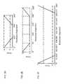
- FIG. 2Ddepicts an exemplary cyclic correlation function of two magnetic structures having polarity patterns in accordance with a Barker 3 code.
- FIG. 2Edepicts an exemplary cyclic correlation function of two magnetic structures having polarity patterns in accordance with a Barker 5 code.
- FIG. 2Fdepicts an exemplary cyclic correlation function of two magnetic structures having polarity patterns in accordance with a Barker 7 code.
- FIG. 2Gdepicts an exemplary cyclic correlation function of two magnetic structures having polarity patterns in accordance with a Barker 11 code.
- FIG. 2Hdepicts an exemplary cyclic correlation function of two magnetic structures having polarity patterns in accordance with a Barker 13 code.
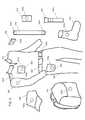
- FIG. 3depicts exemplary locations where an exemplary magnetic attachment system can be used in accordance with the invention.
- FIG. 4Adepicts exemplary use of the magnetic attachment system for applications involving a wall.
- FIG. 4Bdepicts exemplary use of the magnetic attachment system for application involving a vehicle.
- FIG. 5Adepicts exemplary complementary Barker 4 coded magnetic structures having symbols corresponding to alternating polarity arc segments that form concentric circles.
- FIG. 5Bdepicts exemplary magnetic structure polarity pattern designs where the starting point of the Barker 4 code sequence is rotated 90° with each successive concentric circle.
- FIG. 5Cdepicts exemplary magnetic structure polarity pattern designs where the starting point for each Barker 4 pattern is shifted 180 degrees for each odd concentric circle.
- FIG. 5Ddepicts exemplary magnetic structure polarity pattern designs where the odd polarity quadrant shifts with each circle and the polarity of the third and fourth circles is reversed.
- FIG. 5Edepicts how the arc segments of each quadrant of FIG. 5D can be subdivided into alternating polarity portions.
- FIG. 5Fdepicts how portions of the two magnetic structures can be used to provide a bias force.
- FIG. 5Gdepicts complementary magnetic structures comprising two halves of alternating polarity arc segments.
- FIG. 5Hdepicts complementary magnetic structure comprising four alternating polarity quadrants of alternating polarity arc segments.
- FIG. 5Idepicts complementary magnetic structures where the outer four circles comprise eight alternating polarity octants of alternating polarity arc segments and inner most circles that provide an attract bias force.
- Certain described embodimentsmay relate, by way of example but not limitation, to systems and/or apparatuses comprising magnetic structures, magnetic and non-magnetic materials, methods for using magnetic structures, magnetic structures produced via magnetic printing, magnetic structures comprising arrays of discrete magnetic elements, combinations thereof, and so forth.
- Example realizations for such embodimentsmay be facilitated, at least in part, by the use of an emerging, revolutionary technology that may be termed correlated magnetics.
- This revolutionary technology referred to herein as correlated magneticswas first fully described and enabled in the co-assigned U.S. Pat. No. 7,800,471 issued on Sep. 21, 2010, and entitled “A Field Emission System and Method”. The contents of this document are hereby incorporated herein by reference.
- a second generation of a correlated magnetic technologyis described and enabled in the co-assigned U.S. Pat. No. 7,868,721 issued on Jan. 11, 2011, and entitled “A Field Emission System and Method”. The contents of this document are hereby incorporated herein by reference.
- a third generation of a correlated magnetic technologyis described and enabled in the co-assigned U.S. Pat. No. 8,179,219, issued May 15, 2012, and entitled “A Field Emission System and Method”. The contents of this document are hereby incorporated herein by reference.
- Another technology known as correlated inductance, which is related to correlated magneticshas been described and enabled in the co-assigned U.S. Pat. No. 8,115,581 issued on Feb. 14, 2012, and entitled “A System and Method for Producing an Electric Pulse”. The contents of this document are hereby incorporated by reference.
- Material presented hereinmay relate to and/or be implemented in conjunction with multilevel correlated magnetic systems and methods for producing a multilevel correlated magnetic system such as described in U.S. Pat. No. 7,982,568 issued Jul. 19, 2011 which is all incorporated herein by reference in its entirety. Material presented herein may relate to and/or be implemented in conjunction with energy generation systems and methods such as described in U.S. patent application Ser. No. 13/184,543 filed Jul. 17, 2011, which is all incorporated herein by reference in its entirety. Such systems and methods described in U.S. Pat. No. 7,681,256 issued Mar. 23, 2010, U.S. Pat. No. 7,750,781 issued Jul. 6, 2010, U.S. Pat. No. 7,755,462 issued Jul. 13, 2010, U.S. Pat. No.
- a magnetic attachment systemcomprises a male component and a female component, where the male component can be inserted into the female component.
- the male componentcomprises a first magnetic structure having a first plurality of magnetic source regions having a first polarity pattern.
- the female componentcomprises a second magnetic structure having a second plurality of magnetic source regions having a second polarity pattern complementary to said first polarity pattern.
- the male component and female componentare configured such that a peg of the male component can be inserted into a hole within the female component such that the first and second magnetic structures face each other across an interface boundary. While the peg of the male component remains inserted within the hole within the female component the male component can be rotated relative to the female component but translational movement is constrained.
- the first and second polarity patternsmay be in accordance with a cyclic implementation of a code of length N having a cyclic correlation function having a single peak and a plurality of off peaks per code modulo.
- the first and second magnetic structuresproduce a peak attract force when in a complementary rotational alignment position.
- the first and second magnetic structuresproduce an off-peak force that is one of an attract force less than the peak attract force, a substantially zero force, or a repel force when the male component has been rotated relative to the female component plus or minus 360/N degrees from the complementary rotational alignment position.
- the first and second magnetic structureproduce substantially the same off-peak force when the male component has been rotated relative to the female component between plus 360/N degrees from the complementary rotational alignment position and minus 360/N degrees from the complementary rotational alignment position.
- Nis greater than 2, but N can be 2.
- the first and second polarity patternsare irregular polarity patterns.
- the codecan be a Barker code having a length greater than 2.
- Each symbol of the codecan be implemented with a single polarity region, with alternating polarity regions where the alternating polarity regions can be arc segments that form concentric circles, or with an irregular polarity pattern such as a Barker code.
- the arc segmentscan also be subdivided into smaller arc segments having a polarities within a given symbol portion that is part of a given concentric circle.
- One concentric circlecan be rotated relative to another concentric circle and the polarities of opposing concentric circles of the two magnetic structures can be exchanged.
- FIG. 1Adepicts a first exemplary first component 102 a and a first exemplary second component 102 b, which could be made of plastic or any other desired material.
- the first component 102 ahas a peg 104 having a round outer perimeter and has a first circular hole 108 a for accepting a first circular magnetic structure (not shown).
- the second component 102 bhas a second circular hole 108 b for accepting a second circular magnetic structure (not shown) and a third circular hole 108 c having a round outer perimeter for accepting the peg 104 of the first component 102 a.
- the first component 102 a and/or the second component 102 bmay include optional holes 110 , for example counter-sunk holes, enabling attachment to objects (e.g., a wall) using screws, nails, etc.
- optional holes 110for example counter-sunk holes, enabling attachment to objects (e.g., a wall) using screws, nails, etc.
- either or both of the first component 102 a and second component 102 bmay have an adhesive on their back side (i.e., the sides beneath them are not shown). Such an adhesive may have a protective layer that can be removed to expose the adhesive at the time of installation.
- the first component 102 a or the second component 102 bcould be integrated into an object.
- the second circular hole 108 b and third circular hole 108 ccould be formed in wood object such a wood door.
- peg 104could be attached directly to a wall using an adhesive.
- the first component 102 a and/or the second component 102 bcan have notches 112 providing for a better hand grip. Edges of the first component 102 a and/or the second component 102 b can also be rounded (e.g., to prevent harm to fingers). Other optional features include at least one notch 114 or other marking used for identifying one or more alignment positions or notches 116 for removing/replacing magnetic structures (e.g., with a flat head screwdriver).
- the first and second magnetic structurescan be placed into the first and second components in such a way that their peak attach force rotational alignment position corresponds to the alignment of notches 116 or other markings. For example, the magnetic structures can be attached in their peak attach force rotational alignment position and then placed into the first and second components.
- FIG. 1Bdepicts a second exemplary first component 102 a that has a first square hole 122 a for receiving a first square magnetic structure (not shown) and a second exemplary second component 102 b that has a second square hole 122 b for receiving a second square magnetic structure (not shown) and a circular hole 108 for receiving the peg 104 of the first component 102 a.
- a second exemplary second component 102 bthat has a second square hole 122 b for receiving a second square magnetic structure (not shown) and a circular hole 108 for receiving the peg 104 of the first component 102 a.
- the outer perimeter of magnetic sources present on non-circular magnetic materialcan be circular, conform to the shape of the non-circular magnetic material, or have some other shape.
- FIG. 2Adepicts an exemplary method of assembly of an exemplary magnetic attachment system 200 in accordance with the invention.
- a first magnetic structure 202 acomprising four quadrants 204 a - 204 d has been magnetized such that the four quadrants 204 a - 204 d have a first polarity pattern in accordance with a length 4 Barker code (or Barker 4 code).
- a second magnetic structure 202 b having four quadrants 204 e - 204 ghas been magnetized such that the four quadrants 204 e - 204 g have a second polarity pattern that is complementary to the first polarity pattern.
- multiple magnetscan be used to produce either or both of the two magnetic structures in accordance with a Barker 4 code.
- four quarter moon shaped magnetscould be used or a three quarter moon shaped magnet could be used with a quarter moon shaped magnet.
- first and second shunt plates 206 a 206 bare optional first and second shunt plates 206 a 206 b, where typically the first shunt plate 206 a would be placed into the first circular hole 108 a and the second shunt plate 206 b would be placed into the second circular hole 108 b.
- the first magnetic structure 202 acan be placed into the first circular hole 108 a on top of the first shunt plate 206 a and the second magnetic structure 202 a can be placed into the second circular hole 108 b on top of the second shunt plate 206 b.
- Shunt platesare disclosed in pending U.S. patent application Ser. No. 13/374,074, filed Dec. 9, 2011, titled “A System and Method for Affecting Flux of Magnetic Structures”, which is incorporated by reference herein in its entirety.
- an adhesivecan be placed beneath the shunt plates 206 a 206 b and/or beneath the magnetic structures so as to affix them in the first and second components.
- a covering layere.g., of plastic, Titanium, stainless steel, Aluminum, Brass, epoxy, etc.
- a covering layercan be placed on top of the magnetic structures to hold the magnetic structures in place within the first and second components.
- a low-friction materiale.g., Teflon, Kapton
- a high-friction materiale.g., neoprene or latex
- a high-friction materialcan be used on one of the magnetic structures and a low-friction material can be used on the other.
- the first componentmight have a low-friction material applied making it easy to turn the first component to detach the two structures while the second component would have a high-friction material making it more difficult for the object to turn by itself, for example, as a result of movement by the person wearing the garment.
- low and high-friction materialscould be integrated in the first and second components at locations other than where the magnets are placed.
- FIG. 2Bdepicts an exemplary magnetic attachment system 200 after assembly.
- Either the first component 102 a or the second component 102 b as depictedcan be turned over and placed onto the other component such that the peg 104 of the first component 102 a becomes inserted into the third circular hole 208 c of the second component 102 b and the two magnetic structures 202 a 202 b magnetically engage.
- the first component 102 acan be rotated relative to the second component 102 b to vary the rotational alignment of the first magnetic structure.
- the first and second component 102 a 102 bprevent translational movement of the first magnetic structure 202 a relative to the second magnetic structure 202 b.
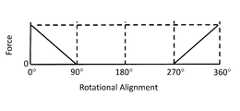
- the two magnetic structuresproduce magnetic forces in accordance with their relative rotational alignment, which corresponds to the cyclic correlation function shown in FIG. 2C .
- a peak attract forcethat is produced at a peak attract force rotational alignment position, which can be denoted 0°/360°.
- the produced forcebecomes substantially cancelled (i.e., a zero force) and remains substantially cancelled for rotational alignments between +360°/4 (i.e., 90°) and ⁇ 360°/4 (i.e., 270°) as depicted in FIG. 2C .
- the two magnetic structuresare in an anti-complementary arrangement (i.e., one of the two structures shown in FIG. 2B is inverted), there is a peak repel force produced at a peak repel force rotational alignment position, which can be denoted 0°/360°.
- a peak repel force rotational alignment positionwhich can be denoted 0°/360°.
- the produced forcebecomes substantially cancelled (i.e., a zero force) and remains substantially cancelled for rotational alignments between +360°/4 (i.e., 90°) and ⁇ 360°/4 (i.e., 270°) as depicted in FIG. 2C .
- FIG. 2Ddepicts the cyclic correlation function of complementary magnetic structures having polarity patterns in accordance with a Barker 3 code.
- FIG. 2Edepicts the cyclic correlation function of complementary magnetic structures having polarity patterns in accordance with a Barker 5 code.
- FIG. 2Fdepicts the cyclic correlation function of complementary magnetic structures having polarity patterns in accordance with a Barker 7 code.
- FIG. 2Gdepicts the cyclic correlation function of complementary magnetic structures having polarity patterns in accordance with a Barker 11 code.
- FIG. 2Hdepicts the cyclic correlation function of complementary magnetic structures having polarity patterns in accordance with a Barker 13 code.
- Barker 4 codeany of the other Barker codes can be used in accordance with the present invention.
- pseudorandom codescan be used as well as other such codes, as has been previously disclosed.
- FIG. 3depicts exemplary locations were a magnetic attachment system can be used.
- a first component 102 acan be placed inside a garment such as in the pocket 303 of a shirt 302 or pocket 305 of a pair of pants 304 .
- the garment materialwill be between the first and second magnetic structures.
- First components 102can be integrated into a sleeve 307 or in a shoulder portion of the garment or perhaps integrated with a belt 306 .
- first componentscan be integrated into a hat 308 , a knapsack 310 , or a shoe 312 .
- Such first componentsenable various types of objects having integrated second components 102 b to be attached such as a flashlight 314 , strap 316 , electronic device 318 (e.g., a cell phone, PDA, etc.), or a camera 320 .
- a flashlight 314e.g., a flashlight, strap 316 , electronic device 318 (e.g., a cell phone, PDA, etc.), or a camera 320 .
- a flashlight 314e.g., strap 316 , electronic device 318 (e.g., a cell phone, PDA, etc.), or a camera 320 .
- a flashlight 314e.g., a flashlight 314
- strap 316e.g., a flashlight, strap 316 , electronic device 318 (e.g., a cell phone, PDA, etc.), or a camera 320 .
- electronic device 318e.g., a cell phone, PDA, etc.
- camera 320
- FIG. 4Adepicts exemplary use of the magnetic attachment system 200 for applications involving a wall 402 , where various types of objects that might need to be attached to a wall where it might be desirable to remove them. Examples of such objects include a picture 404 , a fire extinguisher 406 , a curtain rod holder 408 , and an electronic device 410 .
- FIG. 4Bdepicts an exemplary motorized vehicle 412 where a magnetic attachment system 200 might be used on top of the vehicle (e.g., for attaching a sign) or some other external surface of the vehicle or the system 200 might be used to attach an object (e.g., a PDA, GPS) to a dashboard or other internal surface of a vehicle.
- a vehiclemay be a car, a truck, an emergency vehicle, a train, a boat, a plane, a RV, a motorcycle, etc.
- the magnetic attachment system of the present inventioncan be used to attach two objects.
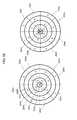
- FIG. 5Adepicts complementary Barker 4 coded magnetic structures where each ‘symbol’ of the Barker 4 code corresponds to alternating polarity arc segments that together form five concentric Barker 4 coded circles 502 a - 502 e.
- each ‘symbol’ of the Barker 4 codecorresponds to alternating polarity arc segments that together form five concentric Barker 4 coded circles 502 a - 502 e.
- increasing or decreasing the number of concentric circlescontrols the amount of tensile forces produced and the throw of the two magnetic structures, which also the magnetic structures be tailored to achieve appropriate forces given the thickness of a material (e.g., clothing) to be placed between them.
- FIG. 5Bdepicts exemplary magnetic structure polarity pattern designs where the starting point of the Barker 4 code sequence is rotated 90° with each successive concentric circle 502 a - 502 e.
- the locations where attract forces are occurring vs. where repel forces are occurringcan be distributed, where it should be understood that prior to such rotation that between 90° and 270° half of the two magnetic structures would be in a repel state and the other half would be in an attract state.
- FIG. 5Cshifts the starting point for each Barker 4 pattern 180 degrees for each odd concentric circle. This design results in two opposing quadrants of opposite polarity and two opposing quadrants having the same alternating polarity pattern.
- FIG. 5Dshifts the odd polarity quadrant 180 with each circle and reverses the polarity of the third and fourth circles.
- FIG. 5Eillustrates how the arc segments of each quadrant can be subdivided into alternating polarity portions where increasing the number of portions per arc segments increases the tensile force, decreases the throw, and increases the rotational shear force (or torque) required to turn one magnetic structure relative to the other.
- FIG. 5Fillustrates how portions of the two magnetic structures can be used to provide a bias force.
- the outer three circleseach have two cyclic Barker 4 code modulos and the inner three circles produce a repel bias force regardless of rotation.
- FIG. 5Idepicts complementary magnetic structures where the outer four circles comprise eight alternating polarity octants of alternating polarity arc segments and inner most circles that provide an attract bias force regardless of rotational alignment.
Landscapes
- Engineering & Computer Science (AREA)
- Physics & Mathematics (AREA)
- Electromagnetism (AREA)
- Power Engineering (AREA)
- General Physics & Mathematics (AREA)
- Theoretical Computer Science (AREA)
- Textile Engineering (AREA)
- Telephone Set Structure (AREA)
Abstract
Description
This application is a continuation in part of non-provisional application Ser. No. 14/035,818, titled: “Magnetic Structures and Methods for Defining Magnetic Structures Using One-Dimensional Codes” filed Sep. 24, 2013 by Fullerton et al. and claims the benefit under 35 USC 119(e) of provisional application 61/851,275, titled “Magnetic Attachment System”, filed Mar. 6, 2013, by Roberts et al.; Ser. No. 14/035,818 is a continuation in part of non-provisional application Ser. No. 13/959,649, titled: “Magnetic Device Using Non Polarized Magnetic Attraction Elements” filed Aug. 5, 2013 by Richards et al. and claims the benefit under 35 USC 119(e) of provisional application 61/744,342, titled “Magnetic Structures and Methods for Defining Magnetic Structures Using One-Dimensional Codes”, filed Sep. 24, 2012 by Roberts; Ser. No. 13/959,649 is a continuation in part of non-provisional Application Ser. No. 13/759,695, titled: “System and Method for Defining Magnetic Structures” filed Feb. 5, 2013 by Fullerton et al., which is a continuation of application Ser. No. 13/481,554, titled: “System and Method for Defining Magnetic Structures”, filed May 25, 2012, by Fullerton et al., U.S. Pat. No. 8,368,495; which is a continuation-in-part of Non-provisional application Ser. No. 13/351,203, titled “A Key System For Enabling Operation Of A Device”, filed Jan. 16, 2012, by Fullerton et al., U.S. Pat. No. 8,314,671; Ser. No. 13/481,554 also claims the benefit under 35 USC 119(e) of provisional application 61/519,664, titled “System and Method for Defining Magnetic Structures”, filed May 25, 2011 by Roberts et al.; Ser. No. 13/351,203 is a continuation of application Ser. No. 13,157,975, titled “Magnetic Attachment System With Low Cross Correlation”, filed Jun. 10, 2011, by Fullerton et al., U.S. Pat. No. 8,098,122, which is a continuation of application Ser. No. 12/952,391, titled: “Magnetic Attachment System”, filed Nov. 23, 2010 by Fullerton et al., U.S. Pat. No. 7,961,069; which is a continuation of application Ser. No. 12/478,911, titled “Magnetically Attachable and Detachable Panel System” filed Jun. 5, 2009 by Fullerton et al., U.S. Pat. No. 7,843,295; Ser. No. 12/952,391 is also a continuation of application Ser. No. 12/478,950, titled “Magnetically Attachable and Detachable Panel Method,” filed Jun. 5, 2009 by Fullerton et al., U.S. Pat. No. 7,843,296; Ser. No. 12/952,391 is also a continuation of application Ser. No. 12/478,969, titled “Coded Magnet Structures for Selective Association of Articles,” filed Jun. 5, 2009 by Fullerton et al., U.S. Pat. No. 7,843,297; Ser. No. 12/952,391 is also a continuation of application Ser. No. 12/479,013, titled “Magnetic Force Profile System Using Coded Magnet Structures,” filed Jun. 5, 2009 by Fullerton et al., U.S. Pat. No. 7,839,247; the preceding four applications above are each a continuation-in-part of Non-provisional application Ser. No. 12/476,952 filed Jun. 2, 2009, by Fullerton et al., titled “A Field Emission System and Method”, which is a continuation-in-part of Non-provisional application Ser. No. 12/322,561, filed Feb. 4, 2009 by Fullerton et al., titled “System and Method for Producing an Electric Pulse”, which is a continuation-in-part application of Non-provisional application Ser. No. 12/358,423, filed Jan. 23, 2009 by Fullerton et al., titled “A Field Emission System and Method”, which is a continuation-in-part application of Non-provisional application Ser. No. 12/123,718, filed May 20, 2008 by Fullerton et al., titled “A Field Emission System and Method”, U.S. Pat. No. 7,800,471, which claims the benefit under 35 USC 119(e) of U.S. Provisional Application Ser. No. 61/123,019, filed Apr. 4, 2008 by Fullerton, titled “A Field Emission System and Method”. The applications and patents listed above are incorporated by reference herein in their entirety.
The present invention relates generally to a system for magnetic attachment. More particularly, the present invention relates to a system for magnetic attachment involving a male component and female component each having complementary magnetic structures.
A magnetic attachment system includes a female component associated with a first object, the female component including a hole and a first magnetic structure having a first plurality of magnetic source regions having a first polarity pattern, and a male component associated with a second object, the male component including a peg that can be inserted into the hole and a second magnetic structure having a second plurality of magnetic source regions having a second polarity pattern complementary to the first polarity pattern. The male component and the female component are configured such that when the peg is inserted into the hole the first and second magnetic structures face each other across an interface boundary enabling magnetic attachment of the first object to the second object, where while the peg remains within said hole said male component can be rotated relative to the female component but translational movement of the male component relative to the female component is constrained, where the first polarity pattern and said second polarity pattern are in accordance with a cyclic implementation of a code of length N, and where said code has a cyclic correlation function having a single peak and a plurality of off peaks per code modulo.
The first and second polarity patterns can be irregular polarity patterns.
The first and second magnetic structures can produce a peak attract force when in a complementary rotational alignment position that magnetically attaches the first object to the second object.
The first and second magnetic structures can produce an off-peak force that is an attract force less than the peak attract force when the male component has been rotated relative to the female component plus or minus 360/N degrees from the complementary rotational alignment position and said cyclic implementation of said code includes only one code modulo of said code.
The first and second magnetic structures can produce an off-peak force that is a substantially zero force when the male component has been rotated relative to the female component plus or minus 360/N degrees from the complementary rotational alignment position and said cyclic implementation of said code includes only one code modulo of said code.
The first and second magnetic structures can produce an off-peak force that is a repel force when the male component has been rotated relative to the female component plus or minus 360/N degrees from the complementary rotational alignment position and said cyclic implementation of said code includes only one code modulo of said code.
The code can be a Barker code.
Each symbol of the code can be implemented with one of a region having a first polarity or a region having a second polarity.
Each symbol of the code can be implemented with an irregular polarity pattern.
Each symbol of the code can be a Barker code.
Each symbol of the code can be implemented with alternating polarity regions, where one polarity region can be rotated relative to another polarity region and/or polarities of opposing regions of the first and second magnetic structures can be exchanged.
One of the first object or the second object can be one of a flashlight, a strap, an electronic device, a cell phone, a PDA, a camera, a GPS, a sign, a picture, a fire extinguisher, or a rod holder.
One of the first object or the second object can be one of a wall, a vehicle, or a garment.
At least one of the male component or the female component can include at least one of attachment holes enabling attachment to at least one of said first object or said second object using a nail or screw, an adhesive enabling attachment to at least one of said first object or said second object, rounded edges, first notches providing a hand grip, at least one marking for identifying one or more alignment positions, or at least one second notch for removing said at least one of said first magnetic structure or said second magnetic structure using a tool.
The male component can be integrated with the first object.
The female component can be integrated with the second object.
One of the male component or the female component can be placed inside a pocket of a garment.
One of the male component or the second component can be integrated into one of a sleeve, a shoulder portion of a garment, a belt, a hat, a knapsack, or a shoe.
The present invention is described with reference to the accompanying drawings. In the drawings, like reference numbers indicate identical or functionally similar elements. Additionally, the left-most digit(s) of a reference number identifies the drawing in which the reference number first appears.
The present invention will now be described more fully in detail with reference to the accompanying drawings, in which the preferred embodiments of the invention are shown. This invention should not, however, be construed as limited to the embodiments set forth herein; rather, they are provided so that this disclosure will be thorough and complete and will fully convey the scope of the invention to those skilled in the art.
Certain described embodiments may relate, by way of example but not limitation, to systems and/or apparatuses comprising magnetic structures, magnetic and non-magnetic materials, methods for using magnetic structures, magnetic structures produced via magnetic printing, magnetic structures comprising arrays of discrete magnetic elements, combinations thereof, and so forth. Example realizations for such embodiments may be facilitated, at least in part, by the use of an emerging, revolutionary technology that may be termed correlated magnetics. This revolutionary technology referred to herein as correlated magnetics was first fully described and enabled in the co-assigned U.S. Pat. No. 7,800,471 issued on Sep. 21, 2010, and entitled “A Field Emission System and Method”. The contents of this document are hereby incorporated herein by reference. A second generation of a correlated magnetic technology is described and enabled in the co-assigned U.S. Pat. No. 7,868,721 issued on Jan. 11, 2011, and entitled “A Field Emission System and Method”. The contents of this document are hereby incorporated herein by reference. A third generation of a correlated magnetic technology is described and enabled in the co-assigned U.S. Pat. No. 8,179,219, issued May 15, 2012, and entitled “A Field Emission System and Method”. The contents of this document are hereby incorporated herein by reference. Another technology known as correlated inductance, which is related to correlated magnetics, has been described and enabled in the co-assigned U.S. Pat. No. 8,115,581 issued on Feb. 14, 2012, and entitled “A System and Method for Producing an Electric Pulse”. The contents of this document are hereby incorporated by reference.
Material presented herein may relate to and/or be implemented in conjunction with multilevel correlated magnetic systems and methods for producing a multilevel correlated magnetic system such as described in U.S. Pat. No. 7,982,568 issued Jul. 19, 2011 which is all incorporated herein by reference in its entirety. Material presented herein may relate to and/or be implemented in conjunction with energy generation systems and methods such as described in U.S. patent application Ser. No. 13/184,543 filed Jul. 17, 2011, which is all incorporated herein by reference in its entirety. Such systems and methods described in U.S. Pat. No. 7,681,256 issued Mar. 23, 2010, U.S. Pat. No. 7,750,781 issued Jul. 6, 2010, U.S. Pat. No. 7,755,462 issued Jul. 13, 2010, U.S. Pat. No. 7,812,698 issued Oct. 12, 2010, U.S. Pat. Nos. 7,817,002, 7,817,003, 7,817,004, 7,817,005, and 7,817,006 issued Oct. 19, 2010, U.S. Pat. No. 7,821,367 issued Oct. 26, 2010, U.S. Pat. Nos. 7,823,300 and 7,824,083 issued Nov. 2, 2011, U.S. Pat. No. 7,834,729 issued Nov. 16, 2011, U.S. Pat. No. 7,839,247 issued Nov. 23, 2010, U.S. Pat. Nos. 7,843,295, 7,843,296, and 7,843,297 issued Nov. 30, 2010, U.S. Pat. No. 7,893,803 issued Feb. 22, 2011, U.S. Pat. Nos. 7,956,711 and 7,956,712 issued Jun. 7, 2011, U.S. Pat. Nos. 7,958,575, 7,961,068 and 7,961,069 issued Jun. 14, 2011, U.S. Pat. No. 7,963,818 issued Jun. 21, 2011, and U.S. Pat. Nos. 8,015,752 and 8,016,330 issued Sep. 13, 2011, and U.S. Pat. No. 8,035,260 issued Oct. 11, 2011 are all incorporated by reference herein in their entirety.
In accordance with one aspect of the invention, a magnetic attachment system comprises a male component and a female component, where the male component can be inserted into the female component. The male component comprises a first magnetic structure having a first plurality of magnetic source regions having a first polarity pattern. The female component comprises a second magnetic structure having a second plurality of magnetic source regions having a second polarity pattern complementary to said first polarity pattern. The male component and female component are configured such that a peg of the male component can be inserted into a hole within the female component such that the first and second magnetic structures face each other across an interface boundary. While the peg of the male component remains inserted within the hole within the female component the male component can be rotated relative to the female component but translational movement is constrained.
The first and second polarity patterns may be in accordance with a cyclic implementation of a code of length N having a cyclic correlation function having a single peak and a plurality of off peaks per code modulo. The first and second magnetic structures produce a peak attract force when in a complementary rotational alignment position. The first and second magnetic structures produce an off-peak force that is one of an attract force less than the peak attract force, a substantially zero force, or a repel force when the male component has been rotated relative to the female component plus or minus 360/N degrees from the complementary rotational alignment position. The first and second magnetic structure produce substantially the same off-peak force when the male component has been rotated relative to the female component between plus 360/N degrees from the complementary rotational alignment position and minus 360/N degrees from the complementary rotational alignment position.
Typically N is greater than 2, but N can be 2.
Under one arrangement, the first and second polarity patterns are irregular polarity patterns. Under such an arrangement, the code can be a Barker code having a length greater than 2.
Under another arrangement. Each symbol of the code can be implemented with a single polarity region, with alternating polarity regions where the alternating polarity regions can be arc segments that form concentric circles, or with an irregular polarity pattern such as a Barker code. The arc segments can also be subdivided into smaller arc segments having a polarities within a given symbol portion that is part of a given concentric circle. One concentric circle can be rotated relative to another concentric circle and the polarities of opposing concentric circles of the two magnetic structures can be exchanged.
Thefirst component 102aand/or thesecond component 102bmay includeoptional holes 110, for example counter-sunk holes, enabling attachment to objects (e.g., a wall) using screws, nails, etc. Alternatively or additionally, either or both of thefirst component 102aandsecond component 102bmay have an adhesive on their back side (i.e., the sides beneath them are not shown). Such an adhesive may have a protective layer that can be removed to expose the adhesive at the time of installation. Furthermore, thefirst component 102aor thesecond component 102bcould be integrated into an object. For example, the secondcircular hole 108band thirdcircular hole 108ccould be formed in wood object such a wood door. Similarly, peg104 could be attached directly to a wall using an adhesive.
Thefirst component 102aand/or thesecond component 102bcan havenotches 112 providing for a better hand grip. Edges of thefirst component 102aand/or thesecond component 102bcan also be rounded (e.g., to prevent harm to fingers). Other optional features include at least onenotch 114 or other marking used for identifying one or more alignment positions ornotches 116 for removing/replacing magnetic structures (e.g., with a flat head screwdriver). One skilled in the art will understand that the first and second magnetic structures can be placed into the first and second components in such a way that their peak attach force rotational alignment position corresponds to the alignment ofnotches 116 or other markings. For example, the magnetic structures can be attached in their peak attach force rotational alignment position and then placed into the first and second components.
Also shown inFIG. 2A are optional first andsecond shunt plates 206a206b,where typically thefirst shunt plate 206awould be placed into the firstcircular hole 108aand thesecond shunt plate 206bwould be placed into the secondcircular hole 108b.The firstmagnetic structure 202acan be placed into the firstcircular hole 108aon top of thefirst shunt plate 206aand the secondmagnetic structure 202acan be placed into the secondcircular hole 108bon top of thesecond shunt plate 206b.Shunt plates are disclosed in pending U.S. patent application Ser. No. 13/374,074, filed Dec. 9, 2011, titled “A System and Method for Affecting Flux of Magnetic Structures”, which is incorporated by reference herein in its entirety.
Optionally, an adhesive can be placed beneath theshunt plates 206a206band/or beneath the magnetic structures so as to affix them in the first and second components. Alternatively or additionally, a covering layer (e.g., of plastic, Titanium, stainless steel, Aluminum, Brass, epoxy, etc.) can be placed on top of the magnetic structures to hold the magnetic structures in place within the first and second components. Alternatively or additionally a low-friction material (e.g., Teflon, Kapton) can be used to cover one or both of the magnetic structures (or a covering layer on top of one or both of the structures) or a high-friction material (e.g., neoprene or latex) could be used to cover one or both of the magnetic structures (or a covering layer on top of one or both of the structures) or a combination thereof. In one preferred embodiment a high-friction material can be used on one of the magnetic structures and a low-friction material can be used on the other. For example, in an application where a first component is placed inside a pocket of a garment and a second component is used to magnetically attach an object, for example, a camera to the garment the first component might have a low-friction material applied making it easy to turn the first component to detach the two structures while the second component would have a high-friction material making it more difficult for the object to turn by itself, for example, as a result of movement by the person wearing the garment. Alternatively, low and high-friction materials could be integrated in the first and second components at locations other than where the magnets are placed.
An alternative method of assembly of a magnetic attachment system in accordance with the present invention is disclosed in U.S. patent Ser. No. 13/779,611 filed Feb. 27, 2013, titled “System for detaching a magnetic structure from a ferromagnetic material”, which is incorporated by reference. With this assembly method, a beveled magnetic structure is placed into a fixture (e.g., the first component or second component) via a hole in the back of the fixture such that a portion of the magnetic structure is exposed via a hole in the front of the fixture, for example a beveled hole, that is smaller than the magnetic structure, where the beveled portion of the magnet and fixture is used to hold the magnetic structure in place. With this approach, the fixture (i.e., first or second component) can be sealed in the back or not, an adhesive can be used or not, etc. but generally the hole in the front of the fixture being smaller than the magnet holds the magnetic structure in place.
All sorts of other well know methods of keeping magnetic structures in place are possible including set screws and the like.
As seen inFIG. 2C , there is a peak attract force that is produced at a peak attract force rotational alignment position, which can be denoted 0°/360°. When one magnetic structure is rotated to a rotational alignment position that is +/−360°/4 (i.e., +/−90°) from the peak attract force rotational alignment position, the produced force becomes substantially cancelled (i.e., a zero force) and remains substantially cancelled for rotational alignments between +360°/4 (i.e., 90°) and −360°/4 (i.e., 270°) as depicted inFIG. 2C . Generally, for Barker codes of a given length N>2, the force produced between two complementary magnetic structures in a cyclic implementation will vary from a peak attract force produced at a peak attract force rotational alignment position to either a substantially zero force (N=4), an attract force less than the peak attract force (N=5 or 13), or a repel force (N=3, 7, or 11) when the relative alignment of the two structures is rotated +/−360°/N from the peak attract force rotational alignment position and the force will remain substantially constant between +360°/N and −360°/N.
It should also be noted that if the two magnetic structures are in an anti-complementary arrangement (i.e., one of the two structures shown inFIG. 2B is inverted), there is a peak repel force produced at a peak repel force rotational alignment position, which can be denoted 0°/360°. When one magnetic structure is rotated to a rotational alignment position that is +/−360°/4 (i.e., +/−90°) from the peak repel force rotational alignment position, the produced force becomes substantially cancelled (i.e., a zero force) and remains substantially cancelled for rotational alignments between +360°/4 (i.e., 90°) and −360°/4 (i.e., 270°) as depicted inFIG. 2C . Generally, for Barker codes of a given length N>2, the force produced between two anti-complementary magnetic structures in a cyclic implementation will produce forces that vary from a peak repel force produced at a peak repel force rotational alignment position to either a substantially zero force (N=4), a repel force less than the peak repel force (N=5 or 13), or an attract force (N=3, 7, or 11) when the relative alignment of the two structures is rotated +/−360°/N from the peak attract force rotational alignment position and the force will remain substantially constant between +360°/N and −360°/N.
Although examples provided herein are all based on a Barker 4 code, any of the other Barker codes can be used in accordance with the present invention. Moreover pseudorandom codes can be used as well as other such codes, as has been previously disclosed.
While particular embodiments of the invention have been described, it will be understood, however, that the invention is not limited thereto, since modifications may be made by those skilled in the art, particularly in light of the foregoing teachings.
Claims (20)
1. A magnetic attachment system, comprising:
a female component associated with a first object, said female component comprising:
a hole; and
a first magnetic structure having a first plurality of magnetic source regions having a first polarity pattern; and
a male component associated with a second object, said male component comprising:
a peg that can be inserted into said hole; and
a second magnetic structure having a second plurality of magnetic source regions having a second polarity pattern complementary to said first polarity pattern, wherein said male component and said female component are configured such that when said peg is inserted into said hole the first and second magnetic structures face each other across an interface boundary enabling magnetic attachment of said first object to said second object, wherein while said peg remains within said hole said male component can be rotated relative to said female component but translational movement of said male component relative to said female component is constrained, wherein said first polarity pattern and said second polarity pattern are in accordance with a cyclic implementation of a code of length N, wherein said code has a cyclic correlation function having a single peak and a plurality of off peaks per code modulo.
2. The magnetic attachment system ofclaim 1 , wherein said first and second polarity patterns are irregular polarity patterns.
3. The magnetic attachment system ofclaim 1 , wherein said first and second magnetic structures produce a peak attract force when in a complementary rotational alignment position, said peak attract force magnetically attaching said first object to said second object.
4. The magnetic attachment system ofclaim 1 , wherein said first and second magnetic structures produce an off-peak force that is an attract force less than the peak attract force when the male component has been rotated relative to the female component plus or minus 360/N degrees from the complementary rotational alignment position and said cyclic implementation of said code includes only one code modulo of said code.
5. The magnetic attachment system ofclaim 1 , wherein said first and second magnetic structures produce an off-peak force that is a substantially zero force when the male component has been rotated relative to the female component plus or minus 360/N degrees from the complementary rotational alignment position and said cyclic implementation of said code includes only one code modulo of said code.
6. The magnetic attachment system ofclaim 1 , wherein said first and second magnetic structures produce an off-peak force that is a repel force when the male component has been rotated relative to the female component plus or minus 360/N degrees from the complementary rotational alignment position and said cyclic implementation of said code includes only one code modulo of said code.
7. The magnetic attachment system ofclaim 1 , wherein said code is a Barker code.
8. The magnetic attachment system ofclaim 1 , wherein each symbol of said code is implemented with one of a region having a first polarity or a region having a second polarity.
9. The magnetic attachment system ofclaim 1 , wherein each symbol of said code is implemented with an irregular polarity pattern.
10. The magnetic attachment system ofclaim 1 , wherein each symbol of said code is a Barker code.
11. The magnetic attachment system ofclaim 1 , wherein each symbol of said code is implemented with alternating polarity regions.
12. The magnetic attachment system ofclaim 11 , wherein one polarity region is rotated relative to another polarity region.
13. The magnetic attachment system ofclaim 11 , wherein polarities of opposing regions of the first and second magnetic structures are exchanged.
14. The magnetic attachment system ofclaim 1 , wherein one of said first object or said second object is one of a flashlight, a strap, an electronic device, a cell phone, a PDA, a camera, a GPS, a sign, a picture, a fire extinguisher, or a rod holder.
15. The magnetic attachment system ofclaim 1 , wherein one of said first object or said second object is one of a wall, a vehicle, or a garment.
16. The magnetic attachment system ofclaim 1 , wherein at least one of said male component or said female component comprises at least one of attachment holes enabling attachment to at least one of said first object or said second object using a nail or screw, an adhesive enabling attachment to at least one of said first object or said second object, rounded edges, first notches providing a hand grip, at least one marking for identifying one or more alignment positions, or at least one second notch for removing said at least one of said first magnetic structure or said second magnetic structure using a tool.
17. The magnetic attachment system ofclaim 1 , wherein said male component is integrated with said first object.
18. The magnetic attachment system ofclaim 1 , wherein said female component is integrated with said second object.
19. The magnetic attachment system ofclaim 1 , wherein one of said male component or said female component is placed inside a pocket of a garment.
20. The magnetic attachment system ofclaim 1 , wherein one of said male component or said second component is integrated into one of a sleeve, a shoulder portion of a garment, a belt, a hat, a knapsack, or a shoe.
Priority Applications (1)
| Application Number | Priority Date | Filing Date | Title |
|---|---|---|---|
| US14/198,191US9105380B2 (en) | 2008-04-04 | 2014-03-05 | Magnetic attachment system |
Applications Claiming Priority (20)
| Application Number | Priority Date | Filing Date | Title |
|---|---|---|---|
| US12301908P | 2008-04-04 | 2008-04-04 | |
| US12/123,718US7800471B2 (en) | 2008-04-04 | 2008-05-20 | Field emission system and method |
| US12/358,423US7868721B2 (en) | 2008-04-04 | 2009-01-23 | Field emission system and method |
| US12/322,561US8115581B2 (en) | 2008-04-04 | 2009-02-04 | Techniques for producing an electrical pulse |
| US12/476,952US8179219B2 (en) | 2008-04-04 | 2009-06-02 | Field emission system and method |
| US12/478,950US7843296B2 (en) | 2008-04-04 | 2009-06-05 | Magnetically attachable and detachable panel method |
| US12/478,969US7843297B2 (en) | 2008-04-04 | 2009-06-05 | Coded magnet structures for selective association of articles |
| US12/478,911US7843295B2 (en) | 2008-04-04 | 2009-06-05 | Magnetically attachable and detachable panel system |
| US12/479,013US7839247B2 (en) | 2008-04-04 | 2009-06-05 | Magnetic force profile system using coded magnet structures |
| US12/952,391US7961069B2 (en) | 2008-04-04 | 2010-11-23 | Magnetic attachment system |
| US201161519664P | 2011-05-25 | 2011-05-25 | |
| US13/157,975US8098122B2 (en) | 2008-04-04 | 2011-06-10 | Magnetic attachment system with low cross correlation |
| US13/351,203US8314671B2 (en) | 2008-04-04 | 2012-01-16 | Key system for enabling operation of a device |
| US13/481,554US8368495B2 (en) | 2008-04-04 | 2012-05-25 | System and method for defining magnetic structures |
| US201261744342P | 2012-09-24 | 2012-09-24 | |
| US13/759,695US8502630B2 (en) | 2008-04-04 | 2013-02-05 | System and method for defining magnetic structures |
| US201361851275P | 2013-03-06 | 2013-03-06 | |
| US13/959,649US8692637B2 (en) | 2008-04-04 | 2013-08-05 | Magnetic device using non polarized magnetic attraction elements |
| US14/035,818US8872608B2 (en) | 2008-04-04 | 2013-09-24 | Magnetic structures and methods for defining magnetic structures using one-dimensional codes |
| US14/198,191US9105380B2 (en) | 2008-04-04 | 2014-03-05 | Magnetic attachment system |
Related Parent Applications (1)
| Application Number | Title | Priority Date | Filing Date |
|---|---|---|---|
| US14/035,818Continuation-In-PartUS8872608B2 (en) | 2008-04-04 | 2013-09-24 | Magnetic structures and methods for defining magnetic structures using one-dimensional codes |
Publications (2)
| Publication Number | Publication Date |
|---|---|
| US20140182088A1 US20140182088A1 (en) | 2014-07-03 |
| US9105380B2true US9105380B2 (en) | 2015-08-11 |
Family
ID=51015527
Family Applications (1)
| Application Number | Title | Priority Date | Filing Date |
|---|---|---|---|
| US14/198,191Expired - Fee RelatedUS9105380B2 (en) | 2008-04-04 | 2014-03-05 | Magnetic attachment system |
Country Status (1)
| Country | Link |
|---|---|
| US (1) | US9105380B2 (en) |
Cited By (5)
| Publication number | Priority date | Publication date | Assignee | Title |
|---|---|---|---|---|
| US20170322481A1 (en)* | 2014-11-21 | 2017-11-09 | Tormaxx Gmbh | Holding element for a camera and camera arrangement, holding element and a helmet |
| US10173292B2 (en)* | 2009-01-23 | 2019-01-08 | Correlated Magnetics Research, Llc | Method for assembling a magnetic attachment mechanism |
| US10943514B1 (en) | 2019-06-05 | 2021-03-09 | Michael Frank O'Keefe | Nondestructive wearable and detachable display assembly |
| WO2021168120A1 (en) | 2020-02-20 | 2021-08-26 | Magnetic Mechanisms L.L.C. | Detachable magnet device |
| US11801920B2 (en) | 2019-09-09 | 2023-10-31 | Bryan Thompson | Lateral displacement surf system |
Families Citing this family (19)
| Publication number | Priority date | Publication date | Assignee | Title |
|---|---|---|---|---|
| US10221005B2 (en)* | 2011-07-27 | 2019-03-05 | Lewis William James, JR. | Magnetic thermally insulated enclosure |
| ITRM20120126A1 (en)* | 2012-03-29 | 2013-09-30 | Salvatore Fonzo | REMOVABLE MAGNETIC CLOSING SYSTEM |
| US9561429B2 (en)* | 2014-10-30 | 2017-02-07 | Stern Pinball, Inc. | Electromagnet for an amusement game device |
| CN107409156A (en)* | 2015-01-10 | 2017-11-28 | 马尔西奥·马克·阿布雷乌 | Support system for electronic devices |
| ES2541224B1 (en)* | 2015-02-24 | 2016-04-27 | Hans BÄBLER FONT | Mobile support |
| US20160296042A1 (en)* | 2015-04-13 | 2016-10-13 | Kate E. Mudge | Display System |
| US10208903B2 (en)* | 2016-10-26 | 2019-02-19 | Ahmad Eivaz | Wrist band with integrated rotatable light |
| US10111500B2 (en) | 2016-11-08 | 2018-10-30 | Brian Lambert | Self-aligning, quick connect and disconnect magnetic end connectors |
| US10973310B2 (en) | 2017-05-10 | 2021-04-13 | James M. Vlassis | Kits, assemblies and components for use in positioning a device, methods of positioning a device, and positioned devices |
| US20180325247A1 (en)* | 2017-05-10 | 2018-11-15 | James M. Vlassis | Kits, assemblies and components for use in positioning a device, methods of positioning a device, and positioned devices |
| US10319504B2 (en)* | 2017-08-24 | 2019-06-11 | Tseng-Lu Chien | Universal magnetic sealed unit |
| US11696634B2 (en) | 2018-08-09 | 2023-07-11 | Lihie SCHORI | Carrier, magnetically attachable to garment |
| CN113163933A (en)* | 2018-12-17 | 2021-07-23 | 乔纳森·迈克尔·罗查 | Back plate |
| GB2585139B (en)* | 2019-06-12 | 2022-03-09 | Watchguard Video Inc | Magnetic body-worn mounting system and method |
| US20230284746A1 (en)* | 2022-03-14 | 2023-09-14 | Valerie Neeley | Customizable Shoe and Accessory Kit |
| DK181677B1 (en)* | 2022-09-05 | 2024-09-18 | Unicontrol Aps | Mounting system and method for releasably attaching a device to a mounting structure attached to a vehicle |
| US20250064153A1 (en)* | 2023-07-25 | 2025-02-27 | Love Magnet, LLC | Apparel items with magnet |
| CN117297212A (en)* | 2023-09-21 | 2023-12-29 | 奇剧引擎(北京)互动科技有限公司 | Halbach array magnet ring buckle device applied to clothes |
| US12276378B1 (en)* | 2024-09-17 | 2025-04-15 | Thomas HIRSCHMANN | Flexible magnetic mounting system for devices |
Citations (368)
| Publication number | Priority date | Publication date | Assignee | Title |
|---|---|---|---|---|
| US93931A (en) | 1869-08-17 | A m o s w e s t c o t t | ||
| US361248A (en) | 1887-04-12 | Holder for metal articles | ||
| US381968A (en) | 1887-10-12 | 1888-05-01 | Nikola Tesla | Electro-magnetic motor |
| US493858A (en) | 1893-03-21 | Transmission of power | ||
| US675323A (en) | 1900-05-22 | 1901-05-28 | Eugene B Clark | Lifting-magnet. |
| US687292A (en) | 1900-09-06 | 1901-11-26 | David B Carse | Power-transmitting device. |
| US996933A (en) | 1905-12-16 | 1911-07-04 | Otis Elevator Co | Magnetic-traction-wheel-drive elevator. |
| US1081462A (en) | 1912-04-25 | 1913-12-16 | D & W Fuse Company | Magnetic chuck. |
| US1171351A (en) | 1913-03-22 | 1916-02-08 | Neuland Electrical Company Inc | Apparatus for transmitting power. |
| US1236234A (en) | 1917-03-30 | 1917-08-07 | Oscar R Troje | Toy building-block. |
| US1252289A (en) | 1917-10-04 | 1918-01-01 | Thomas E Murray Jr | Method of producing integral projections on metal plates. |
| US1301135A (en) | 1917-03-28 | 1919-04-22 | Kar Engineering Company | Fixture for use with magnetic chucks. |
| US1312546A (en) | 1919-08-12 | Fixture for magnetic chucks | ||
| US1323546A (en) | 1919-12-02 | palosky and s | ||
| US1343751A (en) | 1919-03-19 | 1920-06-15 | Taftpeirce Mfg Company | Adjustable v-block and the like for magnetic chucks |
| US1554236A (en) | 1920-01-27 | 1925-09-22 | Taftpeirce Mfg Company | Waterproof magnetic chuck |
| US1624741A (en) | 1926-12-10 | 1927-04-12 | Louis A Leppke | Display device |
| US1784256A (en) | 1928-10-12 | 1930-12-09 | Harold E Stout | Method of manufacturing sinkers for knitting machines |
| US1895129A (en) | 1931-03-30 | 1933-01-24 | Jones David | Magnetic work-holding device |
| US2048161A (en) | 1934-03-29 | 1936-07-21 | Bosch Robert | Dynamo-electric machine frame |
| FR823395A (en) | 1936-09-28 | 1938-01-19 | Hatot | Improvements in remote electrical control systems and devices, in particular synchronous motors and clocks |
| US2147482A (en) | 1936-12-01 | 1939-02-14 | Gen Electric | Luminaire |
| US2186074A (en) | 1939-05-13 | 1940-01-09 | Koller Steven | Magnetic work holder |
| US2240035A (en) | 1938-03-23 | 1941-04-29 | Catherall Alfred Cyril | Securing device |
| US2243555A (en) | 1940-08-21 | 1941-05-27 | Gen Electric | Magnet gearing |
| US2269149A (en) | 1939-11-24 | 1942-01-06 | Gen Electric | Permanent magnet |
| US2327748A (en) | 1941-04-24 | 1943-08-24 | O S Walker Co Inc | Universal work-holding plate for magnetic chucks |
| US2337248A (en) | 1941-07-21 | 1943-12-21 | Koller Steven | Gauging tool |
| US2337249A (en) | 1941-10-27 | 1943-12-21 | Koller Steven | Wheel dressing tool |
| US2389298A (en) | 1943-03-27 | 1945-11-20 | Ellis Robert | Apparel fastener |
| US2401887A (en) | 1943-08-30 | 1946-06-11 | Sheppard Frank | Magnetic chuck attachment plate |
| US2414653A (en) | 1944-01-10 | 1947-01-21 | Alex E Lookholder | Magnetic holder for brushes and other articles |
| US2438231A (en) | 1946-01-18 | 1948-03-23 | Schultz | Closure for fountain pens and the like |
| US2471634A (en) | 1944-07-27 | 1949-05-31 | Winters & Crampton Corp | Refrigerator closure and seal |
| US2475456A (en) | 1944-08-24 | 1949-07-05 | Walter J Norlander | Magnetic work holder |
| US2508305A (en) | 1948-02-05 | 1950-05-16 | Macy O Teetor | Magnetic door catch |
| US2513226A (en) | 1945-07-11 | 1950-06-27 | Redmond Company Inc | Field structure for rotating electrical equipement |
| US2514927A (en) | 1945-10-24 | 1950-07-11 | American Hardware Corp | Magnetic door holder |
| US2520828A (en) | 1947-12-27 | 1950-08-29 | Carter Motor Company | Motor-generator construction |
| US2565624A (en) | 1949-04-22 | 1951-08-28 | Russell E Phelon | Holder for articles of magnetic material |
| US2570625A (en) | 1947-11-21 | 1951-10-09 | Zimmerman Harry | Magnetic toy blocks |
| US2690349A (en) | 1951-03-26 | 1954-09-28 | Macy O Teetor | Magnetic door catch |
| US2694164A (en) | 1952-02-07 | 1954-11-09 | Walter A Geppelt | Magnetic wheel |
| US2701158A (en) | 1954-05-06 | 1955-02-01 | Lab Equipment Corp | Magnetic door catch |
| US2722617A (en) | 1951-11-28 | 1955-11-01 | Hartford Nat Bank & Trust Comp | Magnetic circuits and devices |
| US2770759A (en) | 1955-02-08 | 1956-11-13 | Amerock Corp | Magnetic assembly |
| US2837366A (en) | 1956-12-24 | 1958-06-03 | Loeb Morris | Magnetic catch |
| US2853331A (en) | 1953-12-23 | 1958-09-23 | Macy O Teetor | Magnetic catch |
| US2888291A (en) | 1956-08-10 | 1959-05-26 | Engineered Products Company | Magnetic catch |
| US2896991A (en) | 1956-07-17 | 1959-07-28 | Magni Power Company | Magnetic door holder |
| US2932545A (en) | 1958-10-31 | 1960-04-12 | Gen Electric | Magnetic door latching arrangement for refrigerator |
| US2935352A (en) | 1954-06-25 | 1960-05-03 | Heppner Sales Co | Magnetic catch |
| US2935353A (en) | 1958-11-13 | 1960-05-03 | Loeb Morris | Magnetic catch |
| US2936437A (en) | 1956-09-20 | 1960-05-10 | United Carr Fastener Corp | Electrical apparatus |
| US2962318A (en) | 1956-01-19 | 1960-11-29 | Macy O Teetor | Magnetic catch |
| US2964613A (en) | 1958-12-09 | 1960-12-13 | Schecter Aaron Francis | Lamp control |
| US3055999A (en) | 1961-05-02 | 1962-09-25 | Alfred R Lucas | Magnetic switch of the snap acting type |
| US3089986A (en) | 1960-03-28 | 1963-05-14 | Raymond A Gauthier | Magnetic work-holder |
| US3102314A (en) | 1959-10-01 | 1963-09-03 | Sterling W Alderfer | Fastener for adjacent surfaces |
| US3151902A (en) | 1962-03-13 | 1964-10-06 | Amerock Corp | Magnetic catch |
| US3204995A (en) | 1963-07-10 | 1965-09-07 | Nat Mfg Co | Magnetic catch |
| US3208296A (en) | 1962-04-26 | 1965-09-28 | Baermann Max | Belt drive device |
| US3238399A (en) | 1960-07-26 | 1966-03-01 | Philips Corp | Self-starting low power synchronous step motor |
| US3273104A (en) | 1964-07-21 | 1966-09-13 | United Carr Inc | Electrical connector unit with snap-in fastener means |
| US3288511A (en) | 1965-07-20 | 1966-11-29 | John B Tavano | Two-part magnetic catch for doors or the like |
| US3301091A (en) | 1963-03-19 | 1967-01-31 | Magnavox Co | Magnetic gearing arrangement |
| US3351368A (en) | 1965-08-05 | 1967-11-07 | Richard K Sweet | Magnetic catch |
| US3382386A (en) | 1968-05-07 | Ibm | Magnetic gears | |
| US3408104A (en) | 1967-04-10 | 1968-10-29 | Rohr Corp | Writing arm type conference chair |
| US3414309A (en) | 1966-06-30 | 1968-12-03 | Nat Lock Co | Magnetic catch assembly |
| US3425729A (en) | 1967-11-17 | 1969-02-04 | Southco | Magnetic latch fastener |
| US3468576A (en) | 1968-02-27 | 1969-09-23 | Ford Motor Co | Magnetic latch |
| US3474366A (en) | 1967-06-30 | 1969-10-21 | Walter W Barney | Magnetic switch assembly for operation by magnetic cards |
| US3500090A (en) | 1966-06-28 | 1970-03-10 | Max Baermann | Stator unit for an electrodynamic device |
| US3521216A (en) | 1968-06-19 | 1970-07-21 | Manuel Jerair Tolegian | Magnetic plug and socket assembly |
| US3645650A (en) | 1969-02-10 | 1972-02-29 | Nikolaus Laing | Magnetic transmission |
| US3668670A (en) | 1969-10-27 | 1972-06-06 | Robert D Andersen | Methods and means for recording and reading magnetic imprints |
| US3684992A (en) | 1970-11-18 | 1972-08-15 | Commissariat A L En | Production of magnetic coils for the creation of intense fields |
| US3690393A (en) | 1971-03-19 | 1972-09-12 | Donna Kramer | Magnetic wheel |
| US3696258A (en) | 1970-07-30 | 1972-10-03 | Gen Time Corp | Electret motors capable of continuous rotation |
| US3790197A (en) | 1972-06-22 | 1974-02-05 | Gen Electric | Magnetic latch |
| US3791309A (en) | 1971-01-09 | 1974-02-12 | M Baermann | Means to guide and suspend a vehicle by magnetic forces |
| US3803433A (en) | 1972-02-17 | 1974-04-09 | Gen Time Corp | Permanent magnet rotor synchronous motor |
| US3802034A (en) | 1970-11-27 | 1974-04-09 | Bell & Howell Co | Quick release magnetic latch |
| US3808577A (en) | 1973-03-05 | 1974-04-30 | W Mathauser | Magnetic self-aligning quick-disconnect for a telephone or other communications equipment |
| US3836801A (en) | 1973-03-07 | 1974-09-17 | Hitachi Ltd | Stator for dc machines |
| US3845430A (en) | 1973-08-23 | 1974-10-29 | Gte Automatic Electric Lab Inc | Pulse latched matrix switches |
| US3893059A (en) | 1974-03-13 | 1975-07-01 | Veeder Industries Inc | Pulse generator with asymmetrical multi-pole magnet |
| US3976316A (en) | 1975-03-10 | 1976-08-24 | American Shower Door Co., Inc. | Magnetic door latch |
| GB1495677A (en) | 1974-06-12 | 1977-12-21 | Nix Steingroeve Elektro Physik | Apparatus for producing selective magnetisation of discrete areas or members |
| US4079558A (en) | 1976-01-28 | 1978-03-21 | Gorhams', Inc. | Magnetic bond storm window |
| US4117431A (en) | 1977-06-13 | 1978-09-26 | General Equipment & Manufacturing Co., Inc. | Magnetic proximity device |
| US4129846A (en) | 1975-08-13 | 1978-12-12 | Yablochnikov B | Inductor for magnetic pulse working of tubular metal articles |
| US4209905A (en) | 1977-05-13 | 1980-07-01 | University Of Sydney | Denture retention |
| US4222489A (en) | 1977-08-22 | 1980-09-16 | Hutter Hans Georg | Clamping devices |
| DE2938782A1 (en) | 1979-09-25 | 1981-04-02 | Siemens AG, 1000 Berlin und 8000 München | Magnetic levitation system for moving body - has pairs of magnets at angle to horizontal providing forces on projections body |
| US4296394A (en) | 1978-02-13 | 1981-10-20 | Ragheb A Kadry | Magnetic switching device for contact-dependent and contactless switching |
| US4340833A (en) | 1979-11-26 | 1982-07-20 | Kangyo Denkikiki Kabushiki Kaisha | Miniature motor coil |
| US4352960A (en) | 1980-09-30 | 1982-10-05 | Baptist Medical Center Of Oklahoma, Inc. | Magnetic transcutaneous mount for external device of an associated implant |
| US4355236A (en) | 1980-04-24 | 1982-10-19 | New England Nuclear Corporation | Variable strength beam line multipole permanent magnets and methods for their use |
| US4399595A (en) | 1981-02-11 | 1983-08-23 | John Yoon | Magnetic closure mechanism |
| US4416127A (en) | 1980-06-09 | 1983-11-22 | Gomez Olea Naveda Mariano | Magneto-electronic locks |
| US4451811A (en) | 1979-07-30 | 1984-05-29 | Litton Systems, Inc. | Magnet structure |
| US4453294A (en) | 1979-10-29 | 1984-06-12 | Tamao Morita | Engageable article using permanent magnet |
| US4517483A (en) | 1983-12-27 | 1985-05-14 | Sundstrand Corporation | Permanent magnet rotor with saturable flux bridges |
| JPS6091011U (en) | 1983-11-30 | 1985-06-21 | 日本精工株式会社 | Batsukuru |
| US4535278A (en) | 1982-04-05 | 1985-08-13 | Telmec Co., Ltd. | Two-dimensional precise positioning device for use in a semiconductor manufacturing apparatus |
| US4547756A (en) | 1983-11-22 | 1985-10-15 | Hamlin, Inc. | Multiple reed switch module |
| JPS60221238A (en) | 1984-04-19 | 1985-11-05 | Kanetsuu Kogyo Kk | Magnetic chuck |
| US4629131A (en) | 1981-02-25 | 1986-12-16 | Cuisinarts, Inc. | Magnetic safety interlock for a food processor utilizing vertically oriented, quadrant coded magnets |
| US4645283A (en) | 1983-01-03 | 1987-02-24 | North American Philips Corporation | Adapter for mounting a fluorescent lamp in an incandescent lamp type socket |
| US4680494A (en) | 1983-07-28 | 1987-07-14 | Michel Grosjean | Multiphase motor with facially magnetized rotor having N/2 pairs of poles per face |
| US4764743A (en) | 1987-10-26 | 1988-08-16 | The United States Of America As Represented By The Secretary Of The Army | Permanent magnet structures for the production of transverse helical fields |
| JPS6430444A (en) | 1987-07-23 | 1989-02-01 | Matsushita Electric Works Ltd | Rotor magnet |
| US4808955A (en) | 1987-10-05 | 1989-02-28 | Bei Electronics, Inc. | Moving coil linear actuator with interleaved magnetic circuits |
| US4837539A (en) | 1987-12-08 | 1989-06-06 | Cameron Iron Works Usa, Inc. | Magnetic sensing proximity detector |
| US4849749A (en) | 1986-02-28 | 1989-07-18 | Honda Lock Manufacturing Co., Ltd. | Electronic lock and key switch having key identifying function |
| US4862128A (en) | 1989-04-27 | 1989-08-29 | The United States Of America As Represented By The Secretary Of The Army | Field adjustable transverse flux sources |
| USH693H (en) | 1989-02-24 | 1989-10-03 | The United States Of America As Represented By The Secretary Of The Army | PYX twister with superconducting confinement |
| EP0345554A1 (en) | 1988-06-10 | 1989-12-13 | TECNOMAGNETE S.p.A. | Magnetic gripping apparatus having circuit for eliminating residual flux |
| US4893103A (en) | 1989-02-24 | 1990-01-09 | The United States Of America As Represented By The Secretary Of The Army | Superconducting PYX structures |
| US4912727A (en) | 1988-10-26 | 1990-03-27 | Grass Ag | Drawer guiding system with automatic closing and opening means |
| US4941236A (en) | 1989-07-06 | 1990-07-17 | Timex Corporation | Magnetic clasp for wristwatch strap |
| US4980593A (en) | 1989-03-02 | 1990-12-25 | The Balbec Corporation | Direct current dynamoelectric machines utilizing high-strength permanent magnets |
| US4994778A (en) | 1989-11-14 | 1991-02-19 | The United States Of America As Represented By The Secretary Of The Army | Adjustable twister |
| US4993950A (en) | 1988-06-20 | 1991-02-19 | Mensor Jr Merrill C | Compliant keeper system for fixed removable bridgework and magnetically retained overdentures |
| US4996457A (en) | 1990-03-28 | 1991-02-26 | The United States Of America As Represented By The United States Department Of Energy | Ultra-high speed permanent magnet axial gap alternator with multiple stators |
| US5013949A (en) | 1990-06-25 | 1991-05-07 | Sundstrand Corporation | Magnetic transmission |
| US5020625A (en) | 1988-09-06 | 1991-06-04 | Suzuki Jidosha Kogyo Kabushiki Kaisha | Motor bicycle provided with article accommodating apparatus |
| US5050276A (en) | 1990-06-13 | 1991-09-24 | Pemberton J C | Magnetic necklace clasp |
| US5062855A (en) | 1987-09-28 | 1991-11-05 | Rincoe Richard G | Artifical limb with movement controlled by reversing electromagnet polarity |
| US5123843A (en) | 1989-03-15 | 1992-06-23 | Elephant Edelmetaal B.V. | Magnet element for a dental prosthesis |
| US5179307A (en) | 1992-02-24 | 1993-01-12 | The United States Of America As Represented By The Secretary Of The Air Force | Direct current brushless motor |
| US5190325A (en) | 1991-04-12 | 1993-03-02 | Technophone Limited | Magnetic catch |
| US5213307A (en) | 1990-11-26 | 1993-05-25 | Alcatel Cit | Gastight manually-operated valve |
| EP0545737A1 (en) | 1991-12-06 | 1993-06-09 | Hughes Aircraft Company | Coded fiducial |
| US5302929A (en) | 1989-01-23 | 1994-04-12 | University Of South Florida | Magnetically actuated positive displacement pump |
| US5309680A (en) | 1992-09-14 | 1994-05-10 | The Standard Products Company | Magnetic seal for refrigerator having double doors |
| US5345207A (en) | 1991-01-25 | 1994-09-06 | Leybold Aktiengesellschaft | Magnet configuration with permanent magnets |
| US5349258A (en) | 1989-11-14 | 1994-09-20 | The United States Of America As Represented By The Secretary Of The Army | Permanent magnet structure for use in electric machinery |
| US5367891A (en) | 1992-06-15 | 1994-11-29 | Yugen Kaisha Furuyama Shouji | Fitting device for accessory |
| US5383049A (en) | 1993-02-10 | 1995-01-17 | The Board Of Trustees Of Leland Stanford University | Elliptically polarizing adjustable phase insertion device |
| US5394132A (en) | 1993-07-19 | 1995-02-28 | Poil; James E. | Magnetic motion producing device |
| US5399933A (en) | 1993-05-20 | 1995-03-21 | Chunghwa Picture Tubes, Ltd. | Magnetic beam adjusting rings with different thickness |
| US5425763A (en) | 1992-08-27 | 1995-06-20 | Stemmann; Hartmut | Magnet arrangement for fastening prostheses, in particular epitheses, such as for example artificial ears and the like |
| US5440997A (en) | 1993-09-27 | 1995-08-15 | Crowley; Walter A. | Magnetic suspension transportation system and method |
| US5461386A (en) | 1994-02-08 | 1995-10-24 | Texas Instruments Incorporated | Inductor/antenna for a recognition system |
| US5485435A (en) | 1990-03-20 | 1996-01-16 | Canon Kabushiki Kaisha | Magnetic field generator in which an end face of a magnetic material member projects from man end face of magnetic field generating cores |
| US5492572A (en) | 1990-09-28 | 1996-02-20 | General Motors Corporation | Method for thermomagnetic encoding of permanent magnet materials |
| US5495221A (en) | 1994-03-09 | 1996-02-27 | The Regents Of The University Of California | Dynamically stable magnetic suspension/bearing system |
| US5512732A (en) | 1990-09-20 | 1996-04-30 | Thermon Manufacturing Company | Switch controlled, zone-type heating cable and method |
| US5570084A (en) | 1994-06-28 | 1996-10-29 | Metricom, Inc. | Method of loose source routing over disparate network types in a packet communication network |
| US5582522A (en) | 1994-04-15 | 1996-12-10 | Johnson; Walter A. | Modular electrical power outlet system |
| US5604960A (en) | 1995-05-19 | 1997-02-25 | Good; Elaine M. | Magnetic garment closure system and method for producing same |
| US5631093A (en) | 1990-09-28 | 1997-05-20 | General Motors Corporation | Magnetically coded device |
| US5631618A (en) | 1994-09-30 | 1997-05-20 | Massachusetts Institute Of Technology | Magnetic arrays |
| US5633555A (en) | 1994-02-23 | 1997-05-27 | U.S. Philips Corporation | Magnetic drive arrangement comprising a plurality of magnetically cooperating parts which are movable relative to one another |
| US5635889A (en) | 1995-09-21 | 1997-06-03 | Permag Corporation | Dipole permanent magnet structure |
| US5637972A (en) | 1993-06-07 | 1997-06-10 | Switched Reluctance Drives, Ltd. | Rotor position encoder having features in decodeable angular positions |
| US5730155A (en) | 1995-03-27 | 1998-03-24 | Allen; Dillis V. | Ethmoidal implant and eyeglass assembly and its method of location in situ |
| US5742036A (en) | 1994-10-04 | 1998-04-21 | Rockwell International Corporation | Method for marking, capturing and decoding machine-readable matrix symbols using magneto-optic imaging techniques |
| US5759054A (en) | 1995-10-06 | 1998-06-02 | Pacific Scientific Company | Locking, wire-in fluorescent light adapter |
| US5788493A (en) | 1994-07-15 | 1998-08-04 | Hitachi Metals, Ltd. | Permanent magnet assembly, keeper and magnetic attachment for denture supporting |
| US5838304A (en) | 1983-11-02 | 1998-11-17 | Microsoft Corporation | Packet-based mouse data protocol |
| US5852393A (en) | 1997-06-02 | 1998-12-22 | Eastman Kodak Company | Apparatus for polarizing rare-earth permanent magnets |
| US5935155A (en) | 1998-03-13 | 1999-08-10 | John Hopkins University, School Of Medicine | Visual prosthesis and method of using same |
| US5956778A (en) | 1997-06-20 | 1999-09-28 | Cressi Sub S.P.A. | Device for regulating the length of a swimming goggles strap |
| US5983406A (en) | 1998-01-27 | 1999-11-16 | Meyerrose; Kurt E. | Adjustable strap for scuba mask |
| US6000484A (en) | 1996-09-25 | 1999-12-14 | Aqua Dynamics, Inc. | Articulating wheeled permanent magnet chassis with high pressure sprayer |
| US6039759A (en) | 1996-02-20 | 2000-03-21 | Baxter International Inc. | Mechanical prosthetic valve with coupled leaflets |
| US6047456A (en) | 1997-04-02 | 2000-04-11 | Industrial Technology Research Institute | Method of designing optimal bi-axial magnetic gears and system of the same |
| US6072251A (en) | 1997-04-28 | 2000-06-06 | Ultratech Stepper, Inc. | Magnetically positioned X-Y stage having six degrees of freedom |
| US6074420A (en) | 1999-01-08 | 2000-06-13 | Board Of Trustees Of The University Of Arkansas | Flexible exint retention fixation for external breast prosthesis |
| US6104108A (en) | 1998-12-22 | 2000-08-15 | Nikon Corporation | Wedge magnet array for linear motor |
| US6118271A (en) | 1995-10-17 | 2000-09-12 | Scientific Generics Limited | Position encoder using saturable reactor interacting with magnetic fields varying with time and with position |
| US6120283A (en) | 1999-10-14 | 2000-09-19 | Dart Industries Inc. | Modular candle holder |
| US6125955A (en) | 1999-03-11 | 2000-10-03 | Aqua Dynamics, Inc. | Magnetic wheel |
| US6142779A (en) | 1999-10-26 | 2000-11-07 | University Of Maryland, Baltimore | Breakaway devices for stabilizing dental casts and method of use |
| US6170131B1 (en) | 1999-06-02 | 2001-01-09 | Kyu Ho Shin | Magnetic buttons and structures thereof |
| US6187041B1 (en) | 1998-12-31 | 2001-02-13 | Scott N. Garonzik | Ocular replacement apparatus and method of coupling a prosthesis to an implant |
| US6188147B1 (en) | 1998-10-02 | 2001-02-13 | Nikon Corporation | Wedge and transverse magnet arrays |
| US6205012B1 (en) | 1996-12-31 | 2001-03-20 | Redcliffe Magtronics Limited | Apparatus for altering the magnetic state of a permanent magnet |
| US6210033B1 (en) | 1999-01-12 | 2001-04-03 | Island Oasis Frozen Cocktail Co., Inc. | Magnetic drive blender |
| US6224374B1 (en) | 2000-06-21 | 2001-05-01 | Louis J. Mayo | Fixed, splinted and removable prosthesis attachment |
| US6234833B1 (en) | 1999-12-03 | 2001-05-22 | Hon Hai Precision Ind. Co., Ltd. | Receptacle electrical connector assembly |
| US6241069B1 (en) | 1990-02-05 | 2001-06-05 | Cummins-Allison Corp. | Intelligent currency handling system |
| US6273918B1 (en) | 1999-08-26 | 2001-08-14 | Jason R. Yuhasz | Magnetic detachment system for prosthetics |
| US6275778B1 (en) | 1997-02-26 | 2001-08-14 | Seiko Instruments Inc. | Location-force target path creator |
| US6285097B1 (en) | 1999-05-11 | 2001-09-04 | Nikon Corporation | Planar electric motor and positioning device having transverse magnets |
| JP2001328483A (en) | 2000-05-19 | 2001-11-27 | Haiuei Toole Syst Kk | Self-advancing marker vehicle using crawler type driving wheel |
| WO2002031945A2 (en) | 2000-10-13 | 2002-04-18 | Clarity, Llc | Magnetic actuation and positioning |
| US6387096B1 (en) | 2000-06-13 | 2002-05-14 | Edward R. Hyde, Jr. | Magnetic array implant and method of treating adjacent bone portions |
| US6422533B1 (en) | 1999-07-09 | 2002-07-23 | Parker-Hannifin Corporation | High force solenoid valve and method of improved solenoid valve performance |
| US20020125977A1 (en) | 2001-03-09 | 2002-09-12 | Vanzoest David | Alternating pole magnetic detent |
| US6457179B1 (en) | 2001-01-05 | 2002-10-01 | Norotos, Inc. | Helmet mount for night vision device |
| US6467326B1 (en) | 1998-04-07 | 2002-10-22 | The Boeing Company | Method of riveting |
| US6535092B1 (en) | 1999-09-21 | 2003-03-18 | Magnetic Solutions (Holdings) Limited | Device for generating a variable magnetic field |
| US6540515B1 (en) | 1996-02-26 | 2003-04-01 | Jyoji Tanaka | Cap-type magnetic attachment, dental keeper, dental magnet and method of taking impression using thereof |
| US6561815B1 (en) | 1999-07-02 | 2003-05-13 | Siegfried Schmidt | Electromechanical connecting device |
| US20030136837A1 (en) | 2000-06-28 | 2003-07-24 | Amon Maurice A. | Use of communication equipment and method for authenticating an item, unit and system for authenticating items, and authenticating device |
| US6599321B2 (en) | 2000-06-13 | 2003-07-29 | Edward R. Hyde, Jr. | Magnetic array implant and prosthesis |
| US6607304B1 (en) | 2000-10-04 | 2003-08-19 | Jds Uniphase Inc. | Magnetic clamp for holding ferromagnetic elements during connection thereof |
| US20030170976A1 (en) | 2002-03-08 | 2003-09-11 | Molla Jaynal A. | Method of applying cladding material on conductive lines of MRAM devices |
| US20030179880A1 (en) | 2002-03-20 | 2003-09-25 | Long-Jyh Pan | Magnetic hinge apparatus |
| US20030187510A1 (en) | 2001-05-04 | 2003-10-02 | Hyde Edward R. | Mobile bearing prostheses |
| US6652278B2 (en) | 2000-09-29 | 2003-11-25 | Aichi Steel Corporation | Dental bar attachment for implants |
| US6653919B2 (en) | 2001-02-02 | 2003-11-25 | Wistron Corp | Magnetic closure apparatus for portable computers |
| US20040003487A1 (en) | 2001-01-19 | 2004-01-08 | Reiter Howard J. | Adjustable magnetic snap fastener |
| US6720698B2 (en) | 2002-03-28 | 2004-04-13 | International Business Machines Corporation | Electrical pulse generator using pseudo-random pole distribution |
| US6747537B1 (en) | 2002-05-29 | 2004-06-08 | Magnet Technology, Inc. | Strip magnets with notches |
| US20040155748A1 (en) | 2003-02-02 | 2004-08-12 | Dietrich Steingroever | Transformer for producing high electrical currents |
| US6821126B2 (en) | 2000-12-14 | 2004-11-23 | Magcode Ag | Electromechanical connecting device |
| US20040244636A1 (en) | 2003-06-06 | 2004-12-09 | Magno Corporation | Adaptive magnetic levitation apparatus and method |
| US20040251759A1 (en) | 2003-06-12 | 2004-12-16 | Hirzel Andrew D. | Radial airgap, transverse flux motor |
| US6842332B1 (en) | 2001-01-04 | 2005-01-11 | Apple Computer, Inc. | Magnetic securing system for a detachable input device |
| US6841910B2 (en) | 2002-10-02 | 2005-01-11 | Quadrant Technology Corp. | Magnetic coupling using halbach type magnet array |
| US6847134B2 (en) | 2000-12-27 | 2005-01-25 | Koninklijke Philips Electronics N.V. | Displacement device |
| US6850139B1 (en) | 1999-03-06 | 2005-02-01 | Imo Institut Fur Mikrostrukturtechnologie Und Optoelektronik E.V. | System for writing magnetic scales |
| US6862748B2 (en) | 2003-03-17 | 2005-03-08 | Norotos Inc | Magnet module for night vision goggles helmet mount |
| US6864773B2 (en) | 2003-04-04 | 2005-03-08 | Applied Materials, Inc. | Variable field magnet apparatus |
| US20050102802A1 (en) | 2002-01-14 | 2005-05-19 | Eric Sitbon | Device for fixing to each other or adjusting parts or pieces of clothing or underwear such as bras |
| US6913471B2 (en) | 2002-11-12 | 2005-07-05 | Gateway Inc. | Offset stackable pass-through signal connector |
| US6927657B1 (en) | 2004-12-17 | 2005-08-09 | Michael Wu | Magnetic pole layout method and a magnetizing device for double-wing opposite attraction soft magnet and a product thereof |
| US20050196484A1 (en) | 2003-01-21 | 2005-09-08 | University Of Southern California | Robotic systems for automated construction |
| US6954968B1 (en) | 1998-12-03 | 2005-10-18 | Eric Sitbon | Device for mutually adjusting or fixing part of garments, shoes or other accessories |
| US20050231046A1 (en) | 2004-04-14 | 2005-10-20 | Canon Kabushiki Kaisha | Stepping motor |
| US20050240263A1 (en) | 2002-12-20 | 2005-10-27 | Fogarty Thomas J | Biologically implantable prosthesis and methods of using the same |
| US20050263549A1 (en) | 2002-06-03 | 2005-12-01 | Scheiner Rupert C | Medical device |
| US6971147B2 (en) | 2002-09-05 | 2005-12-06 | Paul Anthony Halstead | Clip |
| US20050283839A1 (en) | 2002-09-10 | 2005-12-22 | Ingenia Technology Limited | Security device and system |
| US7009874B2 (en) | 2002-05-02 | 2006-03-07 | Micron Technology, Inc. | Low remanence flux concentrator for MRAM devices |
| US20060066428A1 (en) | 2004-09-27 | 2006-03-30 | Mccarthy Shaun D | Low energy magnetic actuator |
| US7031160B2 (en) | 2003-10-07 | 2006-04-18 | The Boeing Company | Magnetically enhanced convection heat sink |
| US7033400B2 (en) | 2002-08-08 | 2006-04-25 | Currier Mark R | Prosthetic coupling device |
| US7038565B1 (en) | 2003-06-09 | 2006-05-02 | Astronautics Corporation Of America | Rotating dipole permanent magnet assembly |
| US7066739B2 (en) | 2002-07-16 | 2006-06-27 | Mcleish Graham John | Connector |
| US7065860B2 (en) | 1998-08-06 | 2006-06-27 | Neomax Co., Ltd. | Method for assembling a magnetic field generator for MRI |
| US7066778B2 (en) | 2002-02-01 | 2006-06-27 | Mega Bloks International S.A.R.L. | Construction kit |
| US20060189259A1 (en) | 2003-01-10 | 2006-08-24 | Samsung Electronics Co., Ltd. | Polishing apparatus and related polishing methods |
| US7097461B2 (en) | 2002-09-13 | 2006-08-29 | Magcode Ag | Electric connecting device |
| US20060198998A1 (en) | 2002-07-15 | 2006-09-07 | Jds Uniphase Corporation | Dynamic appearance-changing optical devices (dacod) printed in a shaped magnetic field including printable fresnel structures |
| US20060198047A1 (en) | 2005-03-01 | 2006-09-07 | Xue Song S | Writer structure with assisted bias |
| US20060214756A1 (en) | 2005-03-25 | 2006-09-28 | Ellihay Corp. | Levitation of objects using magnetic force |
| US7135792B2 (en) | 2004-05-12 | 2006-11-14 | Dexter Magnetic Technologies, Inc. | High field voice coil motor |
| US7137727B2 (en) | 2000-07-31 | 2006-11-21 | Litesnow Llc | Electrical track lighting system |
| US20060290451A1 (en) | 2005-06-23 | 2006-12-28 | Prendergast Jonathon R | Magnetically activated switch |
| US20060293762A1 (en) | 2005-06-25 | 2006-12-28 | Alfred E. Mann Foundation For Scientific Research | Strapless prosthetic arm |
| US7186265B2 (en) | 2003-12-10 | 2007-03-06 | Medtronic, Inc. | Prosthetic cardiac valves and systems and methods for implanting thereof |
| US20070072476A1 (en) | 2005-08-24 | 2007-03-29 | Henry Milan | Universal serial bus hub |
| US20070075594A1 (en) | 2005-03-29 | 2007-04-05 | Sadler Gordon H E | Stepping motor control method |
| US20070103266A1 (en) | 2005-11-07 | 2007-05-10 | High Tech Computer Corp. | Auto-aligning and connecting structure between electronic device and accessory |
| US20070138806A1 (en) | 2005-12-13 | 2007-06-21 | Apple Computer, Inc. | Magnetic latching mechanism |
| WO2007081830A2 (en) | 2006-01-10 | 2007-07-19 | Smartcap, Llc | Magnetic device of slidable adjustment |
| US7264479B1 (en) | 2006-06-02 | 2007-09-04 | Lee Vincent J | Coaxial cable magnetic connector |
| US7276025B2 (en) | 2003-03-20 | 2007-10-02 | Welch Allyn, Inc. | Electrical adapter for medical diagnostic instruments using LEDs as illumination sources |
| US20070255400A1 (en) | 2003-10-23 | 2007-11-01 | Parravicini Roberto E | Prosthetic Valve Apparatus, In Particular for Cardiac Applications |
| US20070267929A1 (en) | 2006-05-16 | 2007-11-22 | Minebea Co., Ltd. | Stator arrangement and rotor arrangement for a transverse flux machine |
| US7311526B2 (en) | 2005-09-26 | 2007-12-25 | Apple Inc. | Magnetic connector for electronic device |
| JP2008035676A (en) | 2006-07-31 | 2008-02-14 | Mitsubishi Electric Corp | MANUFACTURING METHOD FOR LINEAR MOTOR AND MAGNET INSERTION DEVICE USED IN THE METHOD, LINEAR MOTOR STATOR MANUFACTURING DEVICE |
| US7339790B2 (en) | 2004-08-18 | 2008-03-04 | Koninklijke Philips Electronics N.V. | Halogen lamps with mains-to-low voltage drivers |
| US7344380B2 (en) | 2002-09-13 | 2008-03-18 | Magcode Ag | Method and device for producing an electrical connection of sub-assemblies and modules |
| US7351066B2 (en) | 2005-09-26 | 2008-04-01 | Apple Computer, Inc. | Electromagnetic connector for electronic device |
| US7358724B2 (en) | 2005-05-16 | 2008-04-15 | Allegro Microsystems, Inc. | Integrated magnetic flux concentrator |
| US7362018B1 (en) | 2006-01-23 | 2008-04-22 | Brunswick Corporation | Encoder alternator |
| US7364433B2 (en) | 2003-11-10 | 2008-04-29 | Magcode Ag | Electrical connecting apparatus |
| US20080119250A1 (en) | 2006-11-22 | 2008-05-22 | Samsung Techwin Co., Ltd. | Magnetic levitation sliding structure |
| US7381181B2 (en) | 2001-09-10 | 2008-06-03 | Paracor Medical, Inc. | Device for treating heart failure |
| US20080139261A1 (en) | 2006-12-07 | 2008-06-12 | Samsung Techwin Co., Ltd. | Magnetic levitation sliding structure |
| JP2008165974A (en) | 2007-01-04 | 2008-07-17 | Thomson Licensing | Pickup for accessing a movable storage medium and drive device including the pickup |
| US7402175B2 (en) | 2004-05-17 | 2008-07-22 | Massachusetts Eye & Ear Infirmary | Vision prosthesis orientation |
| US20080174392A1 (en) | 2007-01-18 | 2008-07-24 | Samsung Techwin Co., Ltd. | Magnetic levitation sliding structure |
| US20080181804A1 (en) | 2006-11-30 | 2008-07-31 | Anest Iwata Corporation | Drive transmission mechanism between two or more rotary shafts and oil-free fluid machine equipped with the mechanism |
| US20080186683A1 (en) | 2006-10-16 | 2008-08-07 | Ligtenberg Chris A | Magnetic latch mechanism |
| US7416414B2 (en) | 2006-11-30 | 2008-08-26 | Motorola, Inc. | Magnetic member for providing electrical continuity and method for assembling same |
| US20080218299A1 (en) | 2005-11-28 | 2008-09-11 | David Patrick Arnold | Method and Structure for Magnetically-Directed, Self-Assembly of Three-Dimensional Structures |
| US20080224806A1 (en) | 2007-03-16 | 2008-09-18 | Ogden Orval D | Material magnetizer systems |
| US7438726B2 (en) | 2004-05-20 | 2008-10-21 | Erb Robert A | Ball hand prosthesis |
| US7444683B2 (en) | 2005-04-04 | 2008-11-04 | Norotos, Inc. | Helmet mounting assembly with break away connection |
| US20080272868A1 (en) | 2007-05-02 | 2008-11-06 | Prendergast Jonathon R | Magnetically activated switch assembly |
| US7453341B1 (en) | 2004-12-17 | 2008-11-18 | Hildenbrand Jack W | System and method for utilizing magnetic energy |
| US7467948B2 (en) | 2006-06-08 | 2008-12-23 | Nokia Corporation | Magnetic connector for mobile electronic devices |
| US20090021333A1 (en) | 2005-03-09 | 2009-01-22 | Joachim Fiedler | Magnetic Holding Device |
| US7498914B2 (en) | 2004-12-20 | 2009-03-03 | Harmonic Drive Systems Inc. | Method for magnetizing ring magnet and magnetic encoder |
| US20090209173A1 (en) | 2008-02-15 | 2009-08-20 | Marguerite Linne Arledge | Bra including concealed carrying compartments and carrying system |
| US7583500B2 (en) | 2005-12-13 | 2009-09-01 | Apple Inc. | Electronic device having magnetic latching mechanism |
| US20090250576A1 (en) | 2008-04-04 | 2009-10-08 | Cedar Ridge Research Llc | Coded Magnet Structures for Selective Association of Articles |
| WO2009124030A1 (en) | 2008-04-04 | 2009-10-08 | Cedar Ridge Research, Llc | A field emission system and method |
| US20090254196A1 (en) | 2008-04-03 | 2009-10-08 | Cox Brian N | Indirect skeletal coupling & dynamic control of prosthesis |
| US20090251256A1 (en) | 2008-04-04 | 2009-10-08 | Cedar Ridge Research Llc | Coded Linear Magnet Arrays in Two Dimensions |
| US20090278642A1 (en) | 2008-04-04 | 2009-11-12 | Cedar Ridge Research Llc | Field emission system and method |
| US20090289090A1 (en) | 2008-05-20 | 2009-11-26 | Cedar Ridge Research, Llc | Correlated Magnetic Belt and Method for Using the Correlated Magnetic Belt |
| US20090292371A1 (en) | 2008-05-20 | 2009-11-26 | Cedar Ridge Research, Llc. | Correlated Magnetic Prosthetic Device and Method for Using the Correlated Magnetic Prosthetic Device |
| US20090289749A1 (en) | 2008-05-20 | 2009-11-26 | Cedar Ridge Research, Llc. | Apparatuses and Methods Relating to Precision Attachments Between First and Second Components |
| US7658613B1 (en) | 2007-01-16 | 2010-02-09 | Griffin Technology Inc | Magnetic connector |
| US20100033280A1 (en) | 2006-09-07 | 2010-02-11 | Bird Mark D | Conical magnet |
| US7715890B2 (en) | 2006-09-08 | 2010-05-11 | Samsung Techwin Co., Ltd. | Magnetic levitation sliding structure |
| US20100126857A1 (en) | 2005-02-08 | 2010-05-27 | Lab901 Limited | Analysis instrument |
| US20100167576A1 (en) | 2007-05-30 | 2010-07-01 | Zhou nan-qing | Replaceable lamp assembly |
| US7762817B2 (en) | 2008-01-04 | 2010-07-27 | Apple Inc. | System for coupling interfacing parts |
| US7796002B2 (en) | 2004-09-30 | 2010-09-14 | Hitachi Metals, Ltd. | Magnetic field generator for MRI |
| US7799281B2 (en) | 2007-01-16 | 2010-09-21 | Festo Corporation | Flux concentrator for biomagnetic particle transfer device |
| US7828556B2 (en) | 2008-03-31 | 2010-11-09 | Stanton Magnetics, Inc. | Audio magnetic connection and indexing device |
| US7832897B2 (en) | 2008-03-19 | 2010-11-16 | Foxconn Technology Co., Ltd. | LED unit with interlocking legs |
| US7837032B2 (en) | 2007-08-29 | 2010-11-23 | Gathering Storm Holding Co. LLC | Golf bag having magnetic pocket |
| US7868721B2 (en) | 2008-04-04 | 2011-01-11 | Cedar Ridge Research, Llc | Field emission system and method |
| US7871272B2 (en) | 2009-03-20 | 2011-01-18 | Casco Products Corporation | Sliding window magnetic electrical connector |
| US7874856B1 (en) | 2007-01-04 | 2011-01-25 | Schriefer Tavis D | Expanding space saving electrical power connection device |
| US7903397B2 (en) | 2007-01-04 | 2011-03-08 | Whirlpool Corporation | Adapter for coupling a consumer electronic device to an appliance |
| US7905626B2 (en) | 2007-08-16 | 2011-03-15 | Shantha Totada R | Modular lighting apparatus |
| US20110085157A1 (en) | 2008-06-17 | 2011-04-14 | Michael Bloss | Sensor device for the spectrally resolved capture of valuable documents and a corresponding method |
| US20110101088A1 (en) | 2008-04-02 | 2011-05-05 | Sicpa Holdings Sa | Identification and authentication using liquid crystal material markings |
| US8002585B2 (en) | 2009-01-20 | 2011-08-23 | Mainhouse (Xiamen) Electronics Co., Ltd. | Detachable lamp socket |
| US8009001B1 (en) | 2007-02-26 | 2011-08-30 | The Boeing Company | Hyper halbach permanent magnet arrays |
| US20110210636A1 (en) | 2007-07-13 | 2011-09-01 | Doris Kuhlmann-Wilsdorf | Mp-t ii machines |
| US20110234344A1 (en) | 2008-04-04 | 2011-09-29 | Cedar Ridge Research Llc | Magnetic Attachment System with Low Cross Correlation |
| US20110248806A1 (en) | 2010-04-09 | 2011-10-13 | Creative Engineering Solutions, Inc. | Switchable core element-based permanent magnet apparatus |
| US8050714B2 (en) | 2003-04-25 | 2011-11-01 | Apple Inc. | Docking station for media player system |
| US20110279206A1 (en) | 2009-09-22 | 2011-11-17 | Fullerton Larry W | Multilevel Magnetic System and Method for Using Same |
| US8078776B2 (en) | 2004-04-27 | 2011-12-13 | Apple Inc. | Electronic device having a dual key connector |
| US20120007704A1 (en) | 2010-07-08 | 2012-01-12 | Nerl Michael S | Periodic correlated magnetic actuator systems and methods of use thereof |
| US8099964B2 (en) | 2006-09-28 | 2012-01-24 | Kabushiki Kaisha Toshiba | Magnetic refrigerating device and magnetic refrigerating method |
| US20120064309A1 (en) | 2009-04-14 | 2012-03-15 | Snu R&Db Foundation | Method of generating structural color |
| US8138869B1 (en) | 2010-09-17 | 2012-03-20 | Apple Inc. | Accessory device with magnetic attachment |
| US8143982B1 (en) | 2010-09-17 | 2012-03-27 | Apple Inc. | Foldable accessory device |
| US8143983B1 (en) | 2010-09-17 | 2012-03-27 | Apple Inc. | Electronic device with magnetic attachment |
| US20120085753A1 (en) | 2010-10-11 | 2012-04-12 | The Timken Company | Apparatus for induction hardening |
| US8187006B2 (en) | 2009-02-02 | 2012-05-29 | Apex Technologies, Inc | Flexible magnetic interconnects |
| US8242868B2 (en) | 2010-09-17 | 2012-08-14 | Apple Inc. | Methods and apparatus for configuring a magnetic attachment system |
| US8253518B2 (en) | 2010-09-17 | 2012-08-28 | Apple Inc. | Foldable cover for electronic device |
| US8264314B2 (en) | 2009-10-20 | 2012-09-11 | Stream Power, Inc. | Magnetic arrays with increased magnetic flux |
| US20120235519A1 (en) | 2011-03-15 | 2012-09-20 | Motor Excellence Llc | Transverse and/or commutated flux systems having laminated and powdered metal portions |
| US8297367B2 (en) | 2010-05-21 | 2012-10-30 | Schlumberger Technology Corporation | Mechanism for activating a plurality of downhole devices |
| US8344836B2 (en) | 2010-09-17 | 2013-01-01 | Apple Inc. | Protective cover for a tablet computer |
| US8348678B2 (en) | 2010-01-11 | 2013-01-08 | Automotive Industrial Marketing Corp. | Magnetic cable connector systems |
| US8354767B2 (en) | 2008-03-19 | 2013-01-15 | Hoganas Ab (Publ.) | Permanent magnet rotor with flux concentrating pole pieces |
| US8390411B2 (en) | 2010-09-17 | 2013-03-05 | Apple Inc. | Tablet device |
| US8395465B2 (en) | 2010-09-17 | 2013-03-12 | Apple Inc. | Cover for an electric device |
| US8398409B2 (en) | 2008-08-12 | 2013-03-19 | Rosenberger Hochfrequenztechnik Gmbh & Co Kg | Apparatus for producing a connection |
| US8454372B2 (en) | 2011-06-01 | 2013-06-04 | Fu Tai Hua Industry (Shenzhen) Co., Ltd. | Electrical connector with power plug and power socket |
| US20130186807A1 (en) | 2012-01-24 | 2013-07-25 | GM Global Technology Operations LLC | Magnetic separator system and method using spatially modulated magnetic fields |
| US20130186473A1 (en) | 2012-01-24 | 2013-07-25 | GM Global Technology Operations LLC | Magnetorheological fluid-based device and method for use |
| US20130187538A1 (en) | 2010-10-07 | 2013-07-25 | Hewlett-Packard Development Company, L.P. | Emissive dendrimer composition |
| US20130186209A1 (en) | 2012-01-24 | 2013-07-25 | GM Global Technology Operations LLC | System and method for sensing torque and angular position of a shaft |
| US20130192860A1 (en) | 2011-06-24 | 2013-08-01 | Black & Decker Inc. | Electromagnetic mode change mechanism for power tool |
| US20130207758A1 (en) | 2012-02-10 | 2013-08-15 | GM Global Technology Operations LLC | Selectable and controllable detent using spatially modulated magnetic fields |
| US8535088B2 (en) | 2009-10-20 | 2013-09-17 | Apple Inc. | Magnetic connector having a unitary housing |
| US20130252375A1 (en) | 2012-03-26 | 2013-09-26 | Ge Yi | Magnet Assisted Alignment Method for Wafer Bonding and Wafer Level Chip Scale Packaging |
| US20130256274A1 (en) | 2011-02-05 | 2013-10-03 | Roger W. Faulkner | Commutating circuit breaker |
| US20130270056A1 (en) | 2012-04-16 | 2013-10-17 | GM Global Technology Operations LLC | Hybrid coded magnets and sma positive drive clutch |
| US8576034B2 (en) | 2010-07-21 | 2013-11-05 | Apple Inc. | Alignment and connection for devices |
| US20130305705A1 (en) | 2012-05-15 | 2013-11-21 | GM Global Technology Operations LLC | Resettable devices |
| US20130341137A1 (en) | 2012-06-20 | 2013-12-26 | GM Global Technology Operations LLC | High energy density magnetic springs using spatially modulated magnetic fields technology |
| US8616362B1 (en) | 2012-08-03 | 2013-12-31 | GM Global Technology Operations LLC | Spatially modulated magnetic fields for part selection and alignment on a conveyor belt |
| US20140001745A1 (en) | 2012-06-21 | 2014-01-02 | Robert Bosch Gmbh | Quick Connect and Quick Disconnect System and Method of Manipulating a Quick Connect and Quick Disconnect System |
| US20140044972A1 (en) | 2012-08-07 | 2014-02-13 | GM Global Technology Operations LLC | Temporary attachment and alignment of light-weight components using spatially modulated magnetic fields technology |
| US8664045B2 (en) | 2011-03-11 | 2014-03-04 | Lingsen Precision Industries, Ltd. | LED lamp strip and manufacturing process thereof |
| US8664044B2 (en) | 2011-11-02 | 2014-03-04 | Stmicroelectronics Pte Ltd. | Method of fabricating land grid array semiconductor package |
| US20140072261A1 (en) | 2012-09-10 | 2014-03-13 | Corning Cable Systems Llc | Docking stations, electronic devices, and fiber optic cable assemblies having a magnetic optical connection |
| US8702316B2 (en) | 2008-09-30 | 2014-04-22 | Apple Inc. | Magnetic connector with optical signal path |
| US8734024B2 (en) | 2011-11-28 | 2014-05-27 | Corning Cable Systems Llc | Optical couplings having a coded magnetic array, and connector assemblies and electronic devices having the same |
| US20140152252A1 (en) | 2012-12-05 | 2014-06-05 | Lockheed Martin Corporation | Re-configurable coded inductive charging system |
| US8752200B2 (en) | 2011-07-12 | 2014-06-10 | At&T Intellectual Property I, L.P. | Devices, systems and methods for security using magnetic field based identification |
| US8757893B1 (en) | 2013-01-29 | 2014-06-24 | Corning Cable Systems Llc | Optical connector assemblies having alignment components |
| US8774577B2 (en) | 2010-12-07 | 2014-07-08 | Corning Cable Systems Llc | Optical couplings having coded magnetic arrays and devices incorporating the same |
| US8781273B2 (en) | 2010-12-07 | 2014-07-15 | Corning Cable Systems Llc | Ferrule assemblies, connector assemblies, and optical couplings having coded magnetic arrays |
| US20140205235A1 (en) | 2012-09-10 | 2014-07-24 | Corning Cable Systems Llc | Optical connections having magnetic coupling |
| US20140221741A1 (en) | 2013-02-07 | 2014-08-07 | Capso Vision, Inc. | Self Assembly of In-Vivo Capsule System |
| US9636937B2 (en) | 2014-12-16 | 2017-05-02 | Canon Kabushiki Kaisha | Image processing apparatus, image processing method, and storage medium |
- 2014
- 2014-03-05USUS14/198,191patent/US9105380B2/ennot_activeExpired - Fee Related
Patent Citations (408)
| Publication number | Priority date | Publication date | Assignee | Title |
|---|---|---|---|---|
| US1312546A (en) | 1919-08-12 | Fixture for magnetic chucks | ||
| US361248A (en) | 1887-04-12 | Holder for metal articles | ||
| US493858A (en) | 1893-03-21 | Transmission of power | ||
| US93931A (en) | 1869-08-17 | A m o s w e s t c o t t | ||
| US3382386A (en) | 1968-05-07 | Ibm | Magnetic gears | |
| US1323546A (en) | 1919-12-02 | palosky and s | ||
| US381968A (en) | 1887-10-12 | 1888-05-01 | Nikola Tesla | Electro-magnetic motor |
| US675323A (en) | 1900-05-22 | 1901-05-28 | Eugene B Clark | Lifting-magnet. |
| US687292A (en) | 1900-09-06 | 1901-11-26 | David B Carse | Power-transmitting device. |
| US996933A (en) | 1905-12-16 | 1911-07-04 | Otis Elevator Co | Magnetic-traction-wheel-drive elevator. |
| US1081462A (en) | 1912-04-25 | 1913-12-16 | D & W Fuse Company | Magnetic chuck. |
| US1171351A (en) | 1913-03-22 | 1916-02-08 | Neuland Electrical Company Inc | Apparatus for transmitting power. |
| US1301135A (en) | 1917-03-28 | 1919-04-22 | Kar Engineering Company | Fixture for use with magnetic chucks. |
| US1236234A (en) | 1917-03-30 | 1917-08-07 | Oscar R Troje | Toy building-block. |
| US1252289A (en) | 1917-10-04 | 1918-01-01 | Thomas E Murray Jr | Method of producing integral projections on metal plates. |
| US1343751A (en) | 1919-03-19 | 1920-06-15 | Taftpeirce Mfg Company | Adjustable v-block and the like for magnetic chucks |
| US1554236A (en) | 1920-01-27 | 1925-09-22 | Taftpeirce Mfg Company | Waterproof magnetic chuck |
| US1624741A (en) | 1926-12-10 | 1927-04-12 | Louis A Leppke | Display device |
| US1784256A (en) | 1928-10-12 | 1930-12-09 | Harold E Stout | Method of manufacturing sinkers for knitting machines |
| US1895129A (en) | 1931-03-30 | 1933-01-24 | Jones David | Magnetic work-holding device |
| US2048161A (en) | 1934-03-29 | 1936-07-21 | Bosch Robert | Dynamo-electric machine frame |
| FR823395A (en) | 1936-09-28 | 1938-01-19 | Hatot | Improvements in remote electrical control systems and devices, in particular synchronous motors and clocks |
| US2147482A (en) | 1936-12-01 | 1939-02-14 | Gen Electric | Luminaire |
| US2240035A (en) | 1938-03-23 | 1941-04-29 | Catherall Alfred Cyril | Securing device |
| US2186074A (en) | 1939-05-13 | 1940-01-09 | Koller Steven | Magnetic work holder |
| US2269149A (en) | 1939-11-24 | 1942-01-06 | Gen Electric | Permanent magnet |
| US2243555A (en) | 1940-08-21 | 1941-05-27 | Gen Electric | Magnet gearing |
| US2327748A (en) | 1941-04-24 | 1943-08-24 | O S Walker Co Inc | Universal work-holding plate for magnetic chucks |
| US2337248A (en) | 1941-07-21 | 1943-12-21 | Koller Steven | Gauging tool |
| US2337249A (en) | 1941-10-27 | 1943-12-21 | Koller Steven | Wheel dressing tool |
| US2389298A (en) | 1943-03-27 | 1945-11-20 | Ellis Robert | Apparel fastener |
| US2401887A (en) | 1943-08-30 | 1946-06-11 | Sheppard Frank | Magnetic chuck attachment plate |
| US2414653A (en) | 1944-01-10 | 1947-01-21 | Alex E Lookholder | Magnetic holder for brushes and other articles |
| US2471634A (en) | 1944-07-27 | 1949-05-31 | Winters & Crampton Corp | Refrigerator closure and seal |
| US2475456A (en) | 1944-08-24 | 1949-07-05 | Walter J Norlander | Magnetic work holder |
| US2513226A (en) | 1945-07-11 | 1950-06-27 | Redmond Company Inc | Field structure for rotating electrical equipement |
| US2514927A (en) | 1945-10-24 | 1950-07-11 | American Hardware Corp | Magnetic door holder |
| US2438231A (en) | 1946-01-18 | 1948-03-23 | Schultz | Closure for fountain pens and the like |
| US2570625A (en) | 1947-11-21 | 1951-10-09 | Zimmerman Harry | Magnetic toy blocks |
| US2520828A (en) | 1947-12-27 | 1950-08-29 | Carter Motor Company | Motor-generator construction |
| US2508305A (en) | 1948-02-05 | 1950-05-16 | Macy O Teetor | Magnetic door catch |
| US2565624A (en) | 1949-04-22 | 1951-08-28 | Russell E Phelon | Holder for articles of magnetic material |
| US2690349A (en) | 1951-03-26 | 1954-09-28 | Macy O Teetor | Magnetic door catch |
| US2722617A (en) | 1951-11-28 | 1955-11-01 | Hartford Nat Bank & Trust Comp | Magnetic circuits and devices |
| US2694164A (en) | 1952-02-07 | 1954-11-09 | Walter A Geppelt | Magnetic wheel |
| US2853331A (en) | 1953-12-23 | 1958-09-23 | Macy O Teetor | Magnetic catch |
| US2701158A (en) | 1954-05-06 | 1955-02-01 | Lab Equipment Corp | Magnetic door catch |
| US2935352A (en) | 1954-06-25 | 1960-05-03 | Heppner Sales Co | Magnetic catch |
| US2770759A (en) | 1955-02-08 | 1956-11-13 | Amerock Corp | Magnetic assembly |
| US2962318A (en) | 1956-01-19 | 1960-11-29 | Macy O Teetor | Magnetic catch |
| US2896991A (en) | 1956-07-17 | 1959-07-28 | Magni Power Company | Magnetic door holder |
| US2888291A (en) | 1956-08-10 | 1959-05-26 | Engineered Products Company | Magnetic catch |
| US2936437A (en) | 1956-09-20 | 1960-05-10 | United Carr Fastener Corp | Electrical apparatus |
| US2837366A (en) | 1956-12-24 | 1958-06-03 | Loeb Morris | Magnetic catch |
| US2932545A (en) | 1958-10-31 | 1960-04-12 | Gen Electric | Magnetic door latching arrangement for refrigerator |
| US2935353A (en) | 1958-11-13 | 1960-05-03 | Loeb Morris | Magnetic catch |
| US2964613A (en) | 1958-12-09 | 1960-12-13 | Schecter Aaron Francis | Lamp control |
| US3102314A (en) | 1959-10-01 | 1963-09-03 | Sterling W Alderfer | Fastener for adjacent surfaces |
| US3089986A (en) | 1960-03-28 | 1963-05-14 | Raymond A Gauthier | Magnetic work-holder |
| US3238399A (en) | 1960-07-26 | 1966-03-01 | Philips Corp | Self-starting low power synchronous step motor |
| US3055999A (en) | 1961-05-02 | 1962-09-25 | Alfred R Lucas | Magnetic switch of the snap acting type |
| US3151902A (en) | 1962-03-13 | 1964-10-06 | Amerock Corp | Magnetic catch |
| US3208296A (en) | 1962-04-26 | 1965-09-28 | Baermann Max | Belt drive device |
| US3301091A (en) | 1963-03-19 | 1967-01-31 | Magnavox Co | Magnetic gearing arrangement |
| US3204995A (en) | 1963-07-10 | 1965-09-07 | Nat Mfg Co | Magnetic catch |
| US3273104A (en) | 1964-07-21 | 1966-09-13 | United Carr Inc | Electrical connector unit with snap-in fastener means |
| US3288511A (en) | 1965-07-20 | 1966-11-29 | John B Tavano | Two-part magnetic catch for doors or the like |
| US3351368A (en) | 1965-08-05 | 1967-11-07 | Richard K Sweet | Magnetic catch |
| US3500090A (en) | 1966-06-28 | 1970-03-10 | Max Baermann | Stator unit for an electrodynamic device |
| US3414309A (en) | 1966-06-30 | 1968-12-03 | Nat Lock Co | Magnetic catch assembly |
| US3408104A (en) | 1967-04-10 | 1968-10-29 | Rohr Corp | Writing arm type conference chair |
| US3474366A (en) | 1967-06-30 | 1969-10-21 | Walter W Barney | Magnetic switch assembly for operation by magnetic cards |
| US3425729A (en) | 1967-11-17 | 1969-02-04 | Southco | Magnetic latch fastener |
| US3468576A (en) | 1968-02-27 | 1969-09-23 | Ford Motor Co | Magnetic latch |
| US3521216A (en) | 1968-06-19 | 1970-07-21 | Manuel Jerair Tolegian | Magnetic plug and socket assembly |
| US3645650A (en) | 1969-02-10 | 1972-02-29 | Nikolaus Laing | Magnetic transmission |
| US3668670A (en) | 1969-10-27 | 1972-06-06 | Robert D Andersen | Methods and means for recording and reading magnetic imprints |
| US3696258A (en) | 1970-07-30 | 1972-10-03 | Gen Time Corp | Electret motors capable of continuous rotation |
| US3684992A (en) | 1970-11-18 | 1972-08-15 | Commissariat A L En | Production of magnetic coils for the creation of intense fields |
| US3802034A (en) | 1970-11-27 | 1974-04-09 | Bell & Howell Co | Quick release magnetic latch |
| US3791309A (en) | 1971-01-09 | 1974-02-12 | M Baermann | Means to guide and suspend a vehicle by magnetic forces |
| US3690393A (en) | 1971-03-19 | 1972-09-12 | Donna Kramer | Magnetic wheel |
| US3803433A (en) | 1972-02-17 | 1974-04-09 | Gen Time Corp | Permanent magnet rotor synchronous motor |
| US3790197A (en) | 1972-06-22 | 1974-02-05 | Gen Electric | Magnetic latch |
| US3808577A (en) | 1973-03-05 | 1974-04-30 | W Mathauser | Magnetic self-aligning quick-disconnect for a telephone or other communications equipment |
| US3836801A (en) | 1973-03-07 | 1974-09-17 | Hitachi Ltd | Stator for dc machines |
| US3845430A (en) | 1973-08-23 | 1974-10-29 | Gte Automatic Electric Lab Inc | Pulse latched matrix switches |
| US3893059A (en) | 1974-03-13 | 1975-07-01 | Veeder Industries Inc | Pulse generator with asymmetrical multi-pole magnet |
| GB1495677A (en) | 1974-06-12 | 1977-12-21 | Nix Steingroeve Elektro Physik | Apparatus for producing selective magnetisation of discrete areas or members |
| US3976316A (en) | 1975-03-10 | 1976-08-24 | American Shower Door Co., Inc. | Magnetic door latch |
| US4129846A (en) | 1975-08-13 | 1978-12-12 | Yablochnikov B | Inductor for magnetic pulse working of tubular metal articles |
| US4079558A (en) | 1976-01-28 | 1978-03-21 | Gorhams', Inc. | Magnetic bond storm window |
| US4209905A (en) | 1977-05-13 | 1980-07-01 | University Of Sydney | Denture retention |
| US4117431A (en) | 1977-06-13 | 1978-09-26 | General Equipment & Manufacturing Co., Inc. | Magnetic proximity device |
| US4222489A (en) | 1977-08-22 | 1980-09-16 | Hutter Hans Georg | Clamping devices |
| US4296394A (en) | 1978-02-13 | 1981-10-20 | Ragheb A Kadry | Magnetic switching device for contact-dependent and contactless switching |
| US4451811A (en) | 1979-07-30 | 1984-05-29 | Litton Systems, Inc. | Magnet structure |
| DE2938782A1 (en) | 1979-09-25 | 1981-04-02 | Siemens AG, 1000 Berlin und 8000 München | Magnetic levitation system for moving body - has pairs of magnets at angle to horizontal providing forces on projections body |
| US4453294A (en) | 1979-10-29 | 1984-06-12 | Tamao Morita | Engageable article using permanent magnet |
| US4453294B1 (en) | 1979-10-29 | 1991-05-28 | Engageable article using permanent magnet | |
| US4453294B2 (en) | 1979-10-29 | 1996-07-23 | Amsco Inc | Engageable article using permanent magnet |
| US4340833A (en) | 1979-11-26 | 1982-07-20 | Kangyo Denkikiki Kabushiki Kaisha | Miniature motor coil |
| US4355236A (en) | 1980-04-24 | 1982-10-19 | New England Nuclear Corporation | Variable strength beam line multipole permanent magnets and methods for their use |
| US4416127A (en) | 1980-06-09 | 1983-11-22 | Gomez Olea Naveda Mariano | Magneto-electronic locks |
| US4352960A (en) | 1980-09-30 | 1982-10-05 | Baptist Medical Center Of Oklahoma, Inc. | Magnetic transcutaneous mount for external device of an associated implant |
| US4399595A (en) | 1981-02-11 | 1983-08-23 | John Yoon | Magnetic closure mechanism |
| US4629131A (en) | 1981-02-25 | 1986-12-16 | Cuisinarts, Inc. | Magnetic safety interlock for a food processor utilizing vertically oriented, quadrant coded magnets |
| US4535278A (en) | 1982-04-05 | 1985-08-13 | Telmec Co., Ltd. | Two-dimensional precise positioning device for use in a semiconductor manufacturing apparatus |
| US4645283A (en) | 1983-01-03 | 1987-02-24 | North American Philips Corporation | Adapter for mounting a fluorescent lamp in an incandescent lamp type socket |
| US4680494A (en) | 1983-07-28 | 1987-07-14 | Michel Grosjean | Multiphase motor with facially magnetized rotor having N/2 pairs of poles per face |
| US5838304A (en) | 1983-11-02 | 1998-11-17 | Microsoft Corporation | Packet-based mouse data protocol |
| US4547756A (en) | 1983-11-22 | 1985-10-15 | Hamlin, Inc. | Multiple reed switch module |
| JPS6091011U (en) | 1983-11-30 | 1985-06-21 | 日本精工株式会社 | Batsukuru |
| US4517483A (en) | 1983-12-27 | 1985-05-14 | Sundstrand Corporation | Permanent magnet rotor with saturable flux bridges |
| JPS60221238A (en) | 1984-04-19 | 1985-11-05 | Kanetsuu Kogyo Kk | Magnetic chuck |
| US4849749A (en) | 1986-02-28 | 1989-07-18 | Honda Lock Manufacturing Co., Ltd. | Electronic lock and key switch having key identifying function |
| JPS6430444A (en) | 1987-07-23 | 1989-02-01 | Matsushita Electric Works Ltd | Rotor magnet |
| US5062855A (en) | 1987-09-28 | 1991-11-05 | Rincoe Richard G | Artifical limb with movement controlled by reversing electromagnet polarity |
| US4808955A (en) | 1987-10-05 | 1989-02-28 | Bei Electronics, Inc. | Moving coil linear actuator with interleaved magnetic circuits |
| US4764743A (en) | 1987-10-26 | 1988-08-16 | The United States Of America As Represented By The Secretary Of The Army | Permanent magnet structures for the production of transverse helical fields |
| US4837539A (en) | 1987-12-08 | 1989-06-06 | Cameron Iron Works Usa, Inc. | Magnetic sensing proximity detector |
| US4956625A (en) | 1988-06-10 | 1990-09-11 | Tecnomagnete S.P.A. | Magnetic gripping apparatus having circuit for eliminating residual flux |
| EP0345554A1 (en) | 1988-06-10 | 1989-12-13 | TECNOMAGNETE S.p.A. | Magnetic gripping apparatus having circuit for eliminating residual flux |
| US4993950A (en) | 1988-06-20 | 1991-02-19 | Mensor Jr Merrill C | Compliant keeper system for fixed removable bridgework and magnetically retained overdentures |
| US5020625A (en) | 1988-09-06 | 1991-06-04 | Suzuki Jidosha Kogyo Kabushiki Kaisha | Motor bicycle provided with article accommodating apparatus |
| US4912727A (en) | 1988-10-26 | 1990-03-27 | Grass Ag | Drawer guiding system with automatic closing and opening means |
| US5302929A (en) | 1989-01-23 | 1994-04-12 | University Of South Florida | Magnetically actuated positive displacement pump |
| USH693H (en) | 1989-02-24 | 1989-10-03 | The United States Of America As Represented By The Secretary Of The Army | PYX twister with superconducting confinement |
| US4893103A (en) | 1989-02-24 | 1990-01-09 | The United States Of America As Represented By The Secretary Of The Army | Superconducting PYX structures |
| US4980593A (en) | 1989-03-02 | 1990-12-25 | The Balbec Corporation | Direct current dynamoelectric machines utilizing high-strength permanent magnets |
| US5123843A (en) | 1989-03-15 | 1992-06-23 | Elephant Edelmetaal B.V. | Magnet element for a dental prosthesis |
| US4862128A (en) | 1989-04-27 | 1989-08-29 | The United States Of America As Represented By The Secretary Of The Army | Field adjustable transverse flux sources |
| US4941236A (en) | 1989-07-06 | 1990-07-17 | Timex Corporation | Magnetic clasp for wristwatch strap |
| US4994778A (en) | 1989-11-14 | 1991-02-19 | The United States Of America As Represented By The Secretary Of The Army | Adjustable twister |
| US5349258A (en) | 1989-11-14 | 1994-09-20 | The United States Of America As Represented By The Secretary Of The Army | Permanent magnet structure for use in electric machinery |
| US6241069B1 (en) | 1990-02-05 | 2001-06-05 | Cummins-Allison Corp. | Intelligent currency handling system |
| US5485435A (en) | 1990-03-20 | 1996-01-16 | Canon Kabushiki Kaisha | Magnetic field generator in which an end face of a magnetic material member projects from man end face of magnetic field generating cores |
| US4996457A (en) | 1990-03-28 | 1991-02-26 | The United States Of America As Represented By The United States Department Of Energy | Ultra-high speed permanent magnet axial gap alternator with multiple stators |
| US5050276A (en) | 1990-06-13 | 1991-09-24 | Pemberton J C | Magnetic necklace clasp |
| US5013949A (en) | 1990-06-25 | 1991-05-07 | Sundstrand Corporation | Magnetic transmission |
| US5512732A (en) | 1990-09-20 | 1996-04-30 | Thermon Manufacturing Company | Switch controlled, zone-type heating cable and method |
| US5492572A (en) | 1990-09-28 | 1996-02-20 | General Motors Corporation | Method for thermomagnetic encoding of permanent magnet materials |
| US5631093A (en) | 1990-09-28 | 1997-05-20 | General Motors Corporation | Magnetically coded device |
| US5213307A (en) | 1990-11-26 | 1993-05-25 | Alcatel Cit | Gastight manually-operated valve |
| US5345207A (en) | 1991-01-25 | 1994-09-06 | Leybold Aktiengesellschaft | Magnet configuration with permanent magnets |
| US5190325A (en) | 1991-04-12 | 1993-03-02 | Technophone Limited | Magnetic catch |
| EP0545737A1 (en) | 1991-12-06 | 1993-06-09 | Hughes Aircraft Company | Coded fiducial |
| US5179307A (en) | 1992-02-24 | 1993-01-12 | The United States Of America As Represented By The Secretary Of The Air Force | Direct current brushless motor |
| US5367891A (en) | 1992-06-15 | 1994-11-29 | Yugen Kaisha Furuyama Shouji | Fitting device for accessory |
| US5425763A (en) | 1992-08-27 | 1995-06-20 | Stemmann; Hartmut | Magnet arrangement for fastening prostheses, in particular epitheses, such as for example artificial ears and the like |
| US5309680A (en) | 1992-09-14 | 1994-05-10 | The Standard Products Company | Magnetic seal for refrigerator having double doors |
| US5383049A (en) | 1993-02-10 | 1995-01-17 | The Board Of Trustees Of Leland Stanford University | Elliptically polarizing adjustable phase insertion device |
| US5399933A (en) | 1993-05-20 | 1995-03-21 | Chunghwa Picture Tubes, Ltd. | Magnetic beam adjusting rings with different thickness |
| US5637972A (en) | 1993-06-07 | 1997-06-10 | Switched Reluctance Drives, Ltd. | Rotor position encoder having features in decodeable angular positions |
| US5394132A (en) | 1993-07-19 | 1995-02-28 | Poil; James E. | Magnetic motion producing device |
| US5440997A (en) | 1993-09-27 | 1995-08-15 | Crowley; Walter A. | Magnetic suspension transportation system and method |
| US5461386A (en) | 1994-02-08 | 1995-10-24 | Texas Instruments Incorporated | Inductor/antenna for a recognition system |
| US5633555A (en) | 1994-02-23 | 1997-05-27 | U.S. Philips Corporation | Magnetic drive arrangement comprising a plurality of magnetically cooperating parts which are movable relative to one another |
| US5495221A (en) | 1994-03-09 | 1996-02-27 | The Regents Of The University Of California | Dynamically stable magnetic suspension/bearing system |
| US5582522A (en) | 1994-04-15 | 1996-12-10 | Johnson; Walter A. | Modular electrical power outlet system |
| US5570084A (en) | 1994-06-28 | 1996-10-29 | Metricom, Inc. | Method of loose source routing over disparate network types in a packet communication network |
| US5788493A (en) | 1994-07-15 | 1998-08-04 | Hitachi Metals, Ltd. | Permanent magnet assembly, keeper and magnetic attachment for denture supporting |
| US5631618A (en) | 1994-09-30 | 1997-05-20 | Massachusetts Institute Of Technology | Magnetic arrays |
| US5742036A (en) | 1994-10-04 | 1998-04-21 | Rockwell International Corporation | Method for marking, capturing and decoding machine-readable matrix symbols using magneto-optic imaging techniques |
| US5730155A (en) | 1995-03-27 | 1998-03-24 | Allen; Dillis V. | Ethmoidal implant and eyeglass assembly and its method of location in situ |
| US5604960A (en) | 1995-05-19 | 1997-02-25 | Good; Elaine M. | Magnetic garment closure system and method for producing same |
| US5635889A (en) | 1995-09-21 | 1997-06-03 | Permag Corporation | Dipole permanent magnet structure |
| US5759054A (en) | 1995-10-06 | 1998-06-02 | Pacific Scientific Company | Locking, wire-in fluorescent light adapter |
| US6118271A (en) | 1995-10-17 | 2000-09-12 | Scientific Generics Limited | Position encoder using saturable reactor interacting with magnetic fields varying with time and with position |
| US6039759A (en) | 1996-02-20 | 2000-03-21 | Baxter International Inc. | Mechanical prosthetic valve with coupled leaflets |
| US6540515B1 (en) | 1996-02-26 | 2003-04-01 | Jyoji Tanaka | Cap-type magnetic attachment, dental keeper, dental magnet and method of taking impression using thereof |
| US6000484A (en) | 1996-09-25 | 1999-12-14 | Aqua Dynamics, Inc. | Articulating wheeled permanent magnet chassis with high pressure sprayer |
| US6205012B1 (en) | 1996-12-31 | 2001-03-20 | Redcliffe Magtronics Limited | Apparatus for altering the magnetic state of a permanent magnet |
| US6275778B1 (en) | 1997-02-26 | 2001-08-14 | Seiko Instruments Inc. | Location-force target path creator |
| US6047456A (en) | 1997-04-02 | 2000-04-11 | Industrial Technology Research Institute | Method of designing optimal bi-axial magnetic gears and system of the same |
| US6072251A (en) | 1997-04-28 | 2000-06-06 | Ultratech Stepper, Inc. | Magnetically positioned X-Y stage having six degrees of freedom |
| US5852393A (en) | 1997-06-02 | 1998-12-22 | Eastman Kodak Company | Apparatus for polarizing rare-earth permanent magnets |
| US5956778A (en) | 1997-06-20 | 1999-09-28 | Cressi Sub S.P.A. | Device for regulating the length of a swimming goggles strap |
| US5983406A (en) | 1998-01-27 | 1999-11-16 | Meyerrose; Kurt E. | Adjustable strap for scuba mask |
| US6115849A (en) | 1998-01-27 | 2000-09-12 | Meyerrose; Kurt E. | Adjustable strap for scuba mask |
| US5935155A (en) | 1998-03-13 | 1999-08-10 | John Hopkins University, School Of Medicine | Visual prosthesis and method of using same |
| US6467326B1 (en) | 1998-04-07 | 2002-10-22 | The Boeing Company | Method of riveting |
| US7065860B2 (en) | 1998-08-06 | 2006-06-27 | Neomax Co., Ltd. | Method for assembling a magnetic field generator for MRI |
| US6188147B1 (en) | 1998-10-02 | 2001-02-13 | Nikon Corporation | Wedge and transverse magnet arrays |
| US6954968B1 (en) | 1998-12-03 | 2005-10-18 | Eric Sitbon | Device for mutually adjusting or fixing part of garments, shoes or other accessories |
| US6104108A (en) | 1998-12-22 | 2000-08-15 | Nikon Corporation | Wedge magnet array for linear motor |
| US6187041B1 (en) | 1998-12-31 | 2001-02-13 | Scott N. Garonzik | Ocular replacement apparatus and method of coupling a prosthesis to an implant |
| US6074420A (en) | 1999-01-08 | 2000-06-13 | Board Of Trustees Of The University Of Arkansas | Flexible exint retention fixation for external breast prosthesis |
| US6210033B1 (en) | 1999-01-12 | 2001-04-03 | Island Oasis Frozen Cocktail Co., Inc. | Magnetic drive blender |
| US6850139B1 (en) | 1999-03-06 | 2005-02-01 | Imo Institut Fur Mikrostrukturtechnologie Und Optoelektronik E.V. | System for writing magnetic scales |
| US6125955A (en) | 1999-03-11 | 2000-10-03 | Aqua Dynamics, Inc. | Magnetic wheel |
| US6285097B1 (en) | 1999-05-11 | 2001-09-04 | Nikon Corporation | Planar electric motor and positioning device having transverse magnets |
| US6170131B1 (en) | 1999-06-02 | 2001-01-09 | Kyu Ho Shin | Magnetic buttons and structures thereof |
| US6561815B1 (en) | 1999-07-02 | 2003-05-13 | Siegfried Schmidt | Electromechanical connecting device |
| US6422533B1 (en) | 1999-07-09 | 2002-07-23 | Parker-Hannifin Corporation | High force solenoid valve and method of improved solenoid valve performance |
| US6273918B1 (en) | 1999-08-26 | 2001-08-14 | Jason R. Yuhasz | Magnetic detachment system for prosthetics |
| US6535092B1 (en) | 1999-09-21 | 2003-03-18 | Magnetic Solutions (Holdings) Limited | Device for generating a variable magnetic field |
| US6120283A (en) | 1999-10-14 | 2000-09-19 | Dart Industries Inc. | Modular candle holder |
| US6142779A (en) | 1999-10-26 | 2000-11-07 | University Of Maryland, Baltimore | Breakaway devices for stabilizing dental casts and method of use |
| US6234833B1 (en) | 1999-12-03 | 2001-05-22 | Hon Hai Precision Ind. Co., Ltd. | Receptacle electrical connector assembly |
| JP2001328483A (en) | 2000-05-19 | 2001-11-27 | Haiuei Toole Syst Kk | Self-advancing marker vehicle using crawler type driving wheel |
| US6387096B1 (en) | 2000-06-13 | 2002-05-14 | Edward R. Hyde, Jr. | Magnetic array implant and method of treating adjacent bone portions |
| US7101374B2 (en) | 2000-06-13 | 2006-09-05 | Hyde Jr Edward R | Magnetic array implant |
| US6599321B2 (en) | 2000-06-13 | 2003-07-29 | Edward R. Hyde, Jr. | Magnetic array implant and prosthesis |
| US6224374B1 (en) | 2000-06-21 | 2001-05-01 | Louis J. Mayo | Fixed, splinted and removable prosthesis attachment |
| US20030136837A1 (en) | 2000-06-28 | 2003-07-24 | Amon Maurice A. | Use of communication equipment and method for authenticating an item, unit and system for authenticating items, and authenticating device |
| US7137727B2 (en) | 2000-07-31 | 2006-11-21 | Litesnow Llc | Electrical track lighting system |
| US6652278B2 (en) | 2000-09-29 | 2003-11-25 | Aichi Steel Corporation | Dental bar attachment for implants |
| US6607304B1 (en) | 2000-10-04 | 2003-08-19 | Jds Uniphase Inc. | Magnetic clamp for holding ferromagnetic elements during connection thereof |
| WO2002031945A2 (en) | 2000-10-13 | 2002-04-18 | Clarity, Llc | Magnetic actuation and positioning |
| US6821126B2 (en) | 2000-12-14 | 2004-11-23 | Magcode Ag | Electromechanical connecting device |
| US6847134B2 (en) | 2000-12-27 | 2005-01-25 | Koninklijke Philips Electronics N.V. | Displacement device |
| US6842332B1 (en) | 2001-01-04 | 2005-01-11 | Apple Computer, Inc. | Magnetic securing system for a detachable input device |
| US6457179B1 (en) | 2001-01-05 | 2002-10-01 | Norotos, Inc. | Helmet mount for night vision device |
| US20040003487A1 (en) | 2001-01-19 | 2004-01-08 | Reiter Howard J. | Adjustable magnetic snap fastener |
| US6653919B2 (en) | 2001-02-02 | 2003-11-25 | Wistron Corp | Magnetic closure apparatus for portable computers |
| US20020125977A1 (en) | 2001-03-09 | 2002-09-12 | Vanzoest David | Alternating pole magnetic detent |
| US20030187510A1 (en) | 2001-05-04 | 2003-10-02 | Hyde Edward R. | Mobile bearing prostheses |
| US7381181B2 (en) | 2001-09-10 | 2008-06-03 | Paracor Medical, Inc. | Device for treating heart failure |
| US20050102802A1 (en) | 2002-01-14 | 2005-05-19 | Eric Sitbon | Device for fixing to each other or adjusting parts or pieces of clothing or underwear such as bras |
| US7066778B2 (en) | 2002-02-01 | 2006-06-27 | Mega Bloks International S.A.R.L. | Construction kit |
| US20030170976A1 (en) | 2002-03-08 | 2003-09-11 | Molla Jaynal A. | Method of applying cladding material on conductive lines of MRAM devices |
| US7016492B2 (en) | 2002-03-20 | 2006-03-21 | Benq Corporation | Magnetic hinge apparatus |
| US20030179880A1 (en) | 2002-03-20 | 2003-09-25 | Long-Jyh Pan | Magnetic hinge apparatus |
| US6720698B2 (en) | 2002-03-28 | 2004-04-13 | International Business Machines Corporation | Electrical pulse generator using pseudo-random pole distribution |
| CN1615573A (en) | 2002-03-28 | 2005-05-11 | 国际商业机器公司 | Electrical pulse generator using pseudo-random pole distribution |
| US7009874B2 (en) | 2002-05-02 | 2006-03-07 | Micron Technology, Inc. | Low remanence flux concentrator for MRAM devices |
| US6747537B1 (en) | 2002-05-29 | 2004-06-08 | Magnet Technology, Inc. | Strip magnets with notches |
| US20050263549A1 (en) | 2002-06-03 | 2005-12-01 | Scheiner Rupert C | Medical device |
| US20060198998A1 (en) | 2002-07-15 | 2006-09-07 | Jds Uniphase Corporation | Dynamic appearance-changing optical devices (dacod) printed in a shaped magnetic field including printable fresnel structures |
| US7066739B2 (en) | 2002-07-16 | 2006-06-27 | Mcleish Graham John | Connector |
| US7033400B2 (en) | 2002-08-08 | 2006-04-25 | Currier Mark R | Prosthetic coupling device |
| US6971147B2 (en) | 2002-09-05 | 2005-12-06 | Paul Anthony Halstead | Clip |
| US20050283839A1 (en) | 2002-09-10 | 2005-12-22 | Ingenia Technology Limited | Security device and system |
| US7344380B2 (en) | 2002-09-13 | 2008-03-18 | Magcode Ag | Method and device for producing an electrical connection of sub-assemblies and modules |
| US7097461B2 (en) | 2002-09-13 | 2006-08-29 | Magcode Ag | Electric connecting device |
| US6841910B2 (en) | 2002-10-02 | 2005-01-11 | Quadrant Technology Corp. | Magnetic coupling using halbach type magnet array |
| US6913471B2 (en) | 2002-11-12 | 2005-07-05 | Gateway Inc. | Offset stackable pass-through signal connector |
| US20050240263A1 (en) | 2002-12-20 | 2005-10-27 | Fogarty Thomas J | Biologically implantable prosthesis and methods of using the same |
| US20060189259A1 (en) | 2003-01-10 | 2006-08-24 | Samsung Electronics Co., Ltd. | Polishing apparatus and related polishing methods |
| US20050196484A1 (en) | 2003-01-21 | 2005-09-08 | University Of Southern California | Robotic systems for automated construction |
| US20040155748A1 (en) | 2003-02-02 | 2004-08-12 | Dietrich Steingroever | Transformer for producing high electrical currents |
| US6862748B2 (en) | 2003-03-17 | 2005-03-08 | Norotos Inc | Magnet module for night vision goggles helmet mount |
| US7276025B2 (en) | 2003-03-20 | 2007-10-02 | Welch Allyn, Inc. | Electrical adapter for medical diagnostic instruments using LEDs as illumination sources |
| US6864773B2 (en) | 2003-04-04 | 2005-03-08 | Applied Materials, Inc. | Variable field magnet apparatus |
| US8271038B2 (en) | 2003-04-25 | 2012-09-18 | Apple Inc. | Wireless adapter for media player system |
| US8050714B2 (en) | 2003-04-25 | 2011-11-01 | Apple Inc. | Docking station for media player system |
| US8078224B2 (en) | 2003-04-25 | 2011-12-13 | Apple Inc. | Male plug connector |
| US8165634B2 (en) | 2003-04-25 | 2012-04-24 | Apple Inc. | Female receptacle connector |
| US8467829B2 (en) | 2003-04-25 | 2013-06-18 | Apple Inc. | Wireless adapter for media player system |
| US8190205B2 (en) | 2003-04-25 | 2012-05-29 | Apple Inc. | Male plug connector |
| US7224252B2 (en) | 2003-06-06 | 2007-05-29 | Magno Corporation | Adaptive magnetic levitation apparatus and method |
| US20040244636A1 (en) | 2003-06-06 | 2004-12-09 | Magno Corporation | Adaptive magnetic levitation apparatus and method |
| US7038565B1 (en) | 2003-06-09 | 2006-05-02 | Astronautics Corporation Of America | Rotating dipole permanent magnet assembly |
| US20040251759A1 (en) | 2003-06-12 | 2004-12-16 | Hirzel Andrew D. | Radial airgap, transverse flux motor |
| US7031160B2 (en) | 2003-10-07 | 2006-04-18 | The Boeing Company | Magnetically enhanced convection heat sink |
| US20070255400A1 (en) | 2003-10-23 | 2007-11-01 | Parravicini Roberto E | Prosthetic Valve Apparatus, In Particular for Cardiac Applications |
| US7364433B2 (en) | 2003-11-10 | 2008-04-29 | Magcode Ag | Electrical connecting apparatus |
| US7186265B2 (en) | 2003-12-10 | 2007-03-06 | Medtronic, Inc. | Prosthetic cardiac valves and systems and methods for implanting thereof |
| US20050231046A1 (en) | 2004-04-14 | 2005-10-20 | Canon Kabushiki Kaisha | Stepping motor |
| US8271705B2 (en) | 2004-04-27 | 2012-09-18 | Apple Inc. | Dual key electronic connector |
| US8078776B2 (en) | 2004-04-27 | 2011-12-13 | Apple Inc. | Electronic device having a dual key connector |
| US7135792B2 (en) | 2004-05-12 | 2006-11-14 | Dexter Magnetic Technologies, Inc. | High field voice coil motor |
| US7402175B2 (en) | 2004-05-17 | 2008-07-22 | Massachusetts Eye & Ear Infirmary | Vision prosthesis orientation |
| US7438726B2 (en) | 2004-05-20 | 2008-10-21 | Erb Robert A | Ball hand prosthesis |
| US7339790B2 (en) | 2004-08-18 | 2008-03-04 | Koninklijke Philips Electronics N.V. | Halogen lamps with mains-to-low voltage drivers |
| US20060066428A1 (en) | 2004-09-27 | 2006-03-30 | Mccarthy Shaun D | Low energy magnetic actuator |
| US7796002B2 (en) | 2004-09-30 | 2010-09-14 | Hitachi Metals, Ltd. | Magnetic field generator for MRI |
| US6927657B1 (en) | 2004-12-17 | 2005-08-09 | Michael Wu | Magnetic pole layout method and a magnetizing device for double-wing opposite attraction soft magnet and a product thereof |
| US7453341B1 (en) | 2004-12-17 | 2008-11-18 | Hildenbrand Jack W | System and method for utilizing magnetic energy |
| US7498914B2 (en) | 2004-12-20 | 2009-03-03 | Harmonic Drive Systems Inc. | Method for magnetizing ring magnet and magnetic encoder |
| US20100126857A1 (en) | 2005-02-08 | 2010-05-27 | Lab901 Limited | Analysis instrument |
| US20060198047A1 (en) | 2005-03-01 | 2006-09-07 | Xue Song S | Writer structure with assisted bias |
| US20090021333A1 (en) | 2005-03-09 | 2009-01-22 | Joachim Fiedler | Magnetic Holding Device |
| US20060214756A1 (en) | 2005-03-25 | 2006-09-28 | Ellihay Corp. | Levitation of objects using magnetic force |
| US20070075594A1 (en) | 2005-03-29 | 2007-04-05 | Sadler Gordon H E | Stepping motor control method |
| US7444683B2 (en) | 2005-04-04 | 2008-11-04 | Norotos, Inc. | Helmet mounting assembly with break away connection |
| US7358724B2 (en) | 2005-05-16 | 2008-04-15 | Allegro Microsystems, Inc. | Integrated magnetic flux concentrator |
| US20060290451A1 (en) | 2005-06-23 | 2006-12-28 | Prendergast Jonathon R | Magnetically activated switch |
| US20060293762A1 (en) | 2005-06-25 | 2006-12-28 | Alfred E. Mann Foundation For Scientific Research | Strapless prosthetic arm |
| US20070072476A1 (en) | 2005-08-24 | 2007-03-29 | Henry Milan | Universal serial bus hub |
| US7901216B2 (en) | 2005-09-26 | 2011-03-08 | Apple Inc. | Magnetic connector for electronic device |
| US8177560B2 (en) | 2005-09-26 | 2012-05-15 | Apple Inc. | Magnetic connector for electronic device |
| US8087939B2 (en) | 2005-09-26 | 2012-01-03 | Apple Inc. | Magnetic connector for electronic device |
| US8497753B2 (en) | 2005-09-26 | 2013-07-30 | Apple Inc. | Electromagnetic connector for electronic device |
| US8690582B2 (en) | 2005-09-26 | 2014-04-08 | Apple Inc. | Magnetic connector for electronic device |
| US7351066B2 (en) | 2005-09-26 | 2008-04-01 | Apple Computer, Inc. | Electromagnetic connector for electronic device |
| US7645143B2 (en) | 2005-09-26 | 2010-01-12 | Apple Inc. | Magnetic connector for electronic device |
| US7311526B2 (en) | 2005-09-26 | 2007-12-25 | Apple Inc. | Magnetic connector for electronic device |
| US8435042B2 (en) | 2005-09-26 | 2013-05-07 | Apple Inc. | Magnetic connector for electronic device |
| US20070103266A1 (en) | 2005-11-07 | 2007-05-10 | High Tech Computer Corp. | Auto-aligning and connecting structure between electronic device and accessory |
| US20080218299A1 (en) | 2005-11-28 | 2008-09-11 | David Patrick Arnold | Method and Structure for Magnetically-Directed, Self-Assembly of Three-Dimensional Structures |
| US7583500B2 (en) | 2005-12-13 | 2009-09-01 | Apple Inc. | Electronic device having magnetic latching mechanism |
| US20110026203A1 (en) | 2005-12-13 | 2011-02-03 | Chris Ligtenberg | Electronic device and magnetic latching mechanism therefore |
| US20070138806A1 (en) | 2005-12-13 | 2007-06-21 | Apple Computer, Inc. | Magnetic latching mechanism |
| US7775567B2 (en) | 2005-12-13 | 2010-08-17 | Apple Inc. | Magnetic latching mechanism |
| US20080282517A1 (en) | 2006-01-10 | 2008-11-20 | Felipe Claro | Magnetic device for slidable adjustment |
| WO2007081830A2 (en) | 2006-01-10 | 2007-07-19 | Smartcap, Llc | Magnetic device of slidable adjustment |
| US7362018B1 (en) | 2006-01-23 | 2008-04-22 | Brunswick Corporation | Encoder alternator |
| US20070267929A1 (en) | 2006-05-16 | 2007-11-22 | Minebea Co., Ltd. | Stator arrangement and rotor arrangement for a transverse flux machine |
| US7264479B1 (en) | 2006-06-02 | 2007-09-04 | Lee Vincent J | Coaxial cable magnetic connector |
| US7637746B2 (en) | 2006-06-08 | 2009-12-29 | Nokia Corporation | Magnetic connector for mobile electronic devices |
| US7467948B2 (en) | 2006-06-08 | 2008-12-23 | Nokia Corporation | Magnetic connector for mobile electronic devices |
| JP2008035676A (en) | 2006-07-31 | 2008-02-14 | Mitsubishi Electric Corp | MANUFACTURING METHOD FOR LINEAR MOTOR AND MAGNET INSERTION DEVICE USED IN THE METHOD, LINEAR MOTOR STATOR MANUFACTURING DEVICE |
| US20100033280A1 (en) | 2006-09-07 | 2010-02-11 | Bird Mark D | Conical magnet |
| US7715890B2 (en) | 2006-09-08 | 2010-05-11 | Samsung Techwin Co., Ltd. | Magnetic levitation sliding structure |
| US8099964B2 (en) | 2006-09-28 | 2012-01-24 | Kabushiki Kaisha Toshiba | Magnetic refrigerating device and magnetic refrigerating method |
| US20080186683A1 (en) | 2006-10-16 | 2008-08-07 | Ligtenberg Chris A | Magnetic latch mechanism |
| US20080119250A1 (en) | 2006-11-22 | 2008-05-22 | Samsung Techwin Co., Ltd. | Magnetic levitation sliding structure |
| US7416414B2 (en) | 2006-11-30 | 2008-08-26 | Motorola, Inc. | Magnetic member for providing electrical continuity and method for assembling same |
| US20080181804A1 (en) | 2006-11-30 | 2008-07-31 | Anest Iwata Corporation | Drive transmission mechanism between two or more rotary shafts and oil-free fluid machine equipped with the mechanism |
| US20080139261A1 (en) | 2006-12-07 | 2008-06-12 | Samsung Techwin Co., Ltd. | Magnetic levitation sliding structure |
| JP2008165974A (en) | 2007-01-04 | 2008-07-17 | Thomson Licensing | Pickup for accessing a movable storage medium and drive device including the pickup |
| US7874856B1 (en) | 2007-01-04 | 2011-01-25 | Schriefer Tavis D | Expanding space saving electrical power connection device |
| US7903397B2 (en) | 2007-01-04 | 2011-03-08 | Whirlpool Corporation | Adapter for coupling a consumer electronic device to an appliance |
| US7799281B2 (en) | 2007-01-16 | 2010-09-21 | Festo Corporation | Flux concentrator for biomagnetic particle transfer device |
| US7658613B1 (en) | 2007-01-16 | 2010-02-09 | Griffin Technology Inc | Magnetic connector |
| US20080174392A1 (en) | 2007-01-18 | 2008-07-24 | Samsung Techwin Co., Ltd. | Magnetic levitation sliding structure |
| US7889037B2 (en) | 2007-01-18 | 2011-02-15 | Samsung Techwin Co., Ltd. | Magnetic levitation sliding structure |
| US8009001B1 (en) | 2007-02-26 | 2011-08-30 | The Boeing Company | Hyper halbach permanent magnet arrays |
| US20080224806A1 (en) | 2007-03-16 | 2008-09-18 | Ogden Orval D | Material magnetizer systems |
| US20080272868A1 (en) | 2007-05-02 | 2008-11-06 | Prendergast Jonathon R | Magnetically activated switch assembly |
| US20100167576A1 (en) | 2007-05-30 | 2010-07-01 | Zhou nan-qing | Replaceable lamp assembly |
| US20110210636A1 (en) | 2007-07-13 | 2011-09-01 | Doris Kuhlmann-Wilsdorf | Mp-t ii machines |
| US7905626B2 (en) | 2007-08-16 | 2011-03-15 | Shantha Totada R | Modular lighting apparatus |
| US7837032B2 (en) | 2007-08-29 | 2010-11-23 | Gathering Storm Holding Co. LLC | Golf bag having magnetic pocket |
| US7762817B2 (en) | 2008-01-04 | 2010-07-27 | Apple Inc. | System for coupling interfacing parts |
| US7997906B2 (en) | 2008-01-04 | 2011-08-16 | Apple Inc. | Techniques for coupling interfaces parts using moveable magnetic elements |
| US20090209173A1 (en) | 2008-02-15 | 2009-08-20 | Marguerite Linne Arledge | Bra including concealed carrying compartments and carrying system |
| US8354767B2 (en) | 2008-03-19 | 2013-01-15 | Hoganas Ab (Publ.) | Permanent magnet rotor with flux concentrating pole pieces |
| US7832897B2 (en) | 2008-03-19 | 2010-11-16 | Foxconn Technology Co., Ltd. | LED unit with interlocking legs |
| US7828556B2 (en) | 2008-03-31 | 2010-11-09 | Stanton Magnetics, Inc. | Audio magnetic connection and indexing device |
| US20110101088A1 (en) | 2008-04-02 | 2011-05-05 | Sicpa Holdings Sa | Identification and authentication using liquid crystal material markings |
| US20090254196A1 (en) | 2008-04-03 | 2009-10-08 | Cox Brian N | Indirect skeletal coupling & dynamic control of prosthesis |
| US7839246B2 (en) | 2008-04-04 | 2010-11-23 | Cedar Ridge Research, Llc | Field structure and method for producing a field structure |
| US7868721B2 (en) | 2008-04-04 | 2011-01-11 | Cedar Ridge Research, Llc | Field emission system and method |
| US20110234344A1 (en) | 2008-04-04 | 2011-09-29 | Cedar Ridge Research Llc | Magnetic Attachment System with Low Cross Correlation |
| US20090278642A1 (en) | 2008-04-04 | 2009-11-12 | Cedar Ridge Research Llc | Field emission system and method |
| US7843297B2 (en) | 2008-04-04 | 2010-11-30 | Cedar Ridge Research Llc | Coded magnet structures for selective association of articles |
| US7808349B2 (en) | 2008-04-04 | 2010-10-05 | Cedar Ridge Research, Llc | System and method for producing repeating spatial forces |
| WO2009124030A1 (en) | 2008-04-04 | 2009-10-08 | Cedar Ridge Research, Llc | A field emission system and method |
| US20090250576A1 (en) | 2008-04-04 | 2009-10-08 | Cedar Ridge Research Llc | Coded Magnet Structures for Selective Association of Articles |
| US7812697B2 (en) | 2008-04-04 | 2010-10-12 | Cedar Ridge Research, Llc | Method and system for producing repeating spatial forces |
| US20090251256A1 (en) | 2008-04-04 | 2009-10-08 | Cedar Ridge Research Llc | Coded Linear Magnet Arrays in Two Dimensions |
| US20090289090A1 (en) | 2008-05-20 | 2009-11-26 | Cedar Ridge Research, Llc | Correlated Magnetic Belt and Method for Using the Correlated Magnetic Belt |
| US20090292371A1 (en) | 2008-05-20 | 2009-11-26 | Cedar Ridge Research, Llc. | Correlated Magnetic Prosthetic Device and Method for Using the Correlated Magnetic Prosthetic Device |
| US20090289749A1 (en) | 2008-05-20 | 2009-11-26 | Cedar Ridge Research, Llc. | Apparatuses and Methods Relating to Precision Attachments Between First and Second Components |
| US7817004B2 (en) | 2008-05-20 | 2010-10-19 | Cedar Ridge Research, Llc. | Correlated magnetic prosthetic device and method for using the correlated magnetic prosthetic device |
| US20110085157A1 (en) | 2008-06-17 | 2011-04-14 | Michael Bloss | Sensor device for the spectrally resolved capture of valuable documents and a corresponding method |
| US8398409B2 (en) | 2008-08-12 | 2013-03-19 | Rosenberger Hochfrequenztechnik Gmbh & Co Kg | Apparatus for producing a connection |
| US8770857B2 (en) | 2008-09-30 | 2014-07-08 | Apple Inc. | Magnetic connector with optical signal path |
| US8702316B2 (en) | 2008-09-30 | 2014-04-22 | Apple Inc. | Magnetic connector with optical signal path |
| US8002585B2 (en) | 2009-01-20 | 2011-08-23 | Mainhouse (Xiamen) Electronics Co., Ltd. | Detachable lamp socket |
| US8187006B2 (en) | 2009-02-02 | 2012-05-29 | Apex Technologies, Inc | Flexible magnetic interconnects |
| US7871272B2 (en) | 2009-03-20 | 2011-01-18 | Casco Products Corporation | Sliding window magnetic electrical connector |
| US20120064309A1 (en) | 2009-04-14 | 2012-03-15 | Snu R&Db Foundation | Method of generating structural color |
| WO2010141324A1 (en) | 2009-06-02 | 2010-12-09 | Cedar Ridge Research, Llc. | A field emission system and method |
| US20110279206A1 (en) | 2009-09-22 | 2011-11-17 | Fullerton Larry W | Multilevel Magnetic System and Method for Using Same |
| US8264314B2 (en) | 2009-10-20 | 2012-09-11 | Stream Power, Inc. | Magnetic arrays with increased magnetic flux |
| US8535088B2 (en) | 2009-10-20 | 2013-09-17 | Apple Inc. | Magnetic connector having a unitary housing |
| US8348678B2 (en) | 2010-01-11 | 2013-01-08 | Automotive Industrial Marketing Corp. | Magnetic cable connector systems |
| US20110248806A1 (en) | 2010-04-09 | 2011-10-13 | Creative Engineering Solutions, Inc. | Switchable core element-based permanent magnet apparatus |
| US8297367B2 (en) | 2010-05-21 | 2012-10-30 | Schlumberger Technology Corporation | Mechanism for activating a plurality of downhole devices |
| US20120007704A1 (en) | 2010-07-08 | 2012-01-12 | Nerl Michael S | Periodic correlated magnetic actuator systems and methods of use thereof |
| US8576034B2 (en) | 2010-07-21 | 2013-11-05 | Apple Inc. | Alignment and connection for devices |
| US8242868B2 (en) | 2010-09-17 | 2012-08-14 | Apple Inc. | Methods and apparatus for configuring a magnetic attachment system |
| US8143982B1 (en) | 2010-09-17 | 2012-03-27 | Apple Inc. | Foldable accessory device |
| US8390412B2 (en) | 2010-09-17 | 2013-03-05 | Apple Inc. | Protective cover |
| US8395465B2 (en) | 2010-09-17 | 2013-03-12 | Apple Inc. | Cover for an electric device |
| US8390411B2 (en) | 2010-09-17 | 2013-03-05 | Apple Inc. | Tablet device |
| US8344836B2 (en) | 2010-09-17 | 2013-01-01 | Apple Inc. | Protective cover for a tablet computer |
| US8138869B1 (en) | 2010-09-17 | 2012-03-20 | Apple Inc. | Accessory device with magnetic attachment |
| US8514042B2 (en) | 2010-09-17 | 2013-08-20 | Apple Inc. | Magnetic attachment system |
| US8143983B1 (en) | 2010-09-17 | 2012-03-27 | Apple Inc. | Electronic device with magnetic attachment |
| US8648679B2 (en) | 2010-09-17 | 2014-02-11 | Apple Inc. | Tablet device having a display operable in peek mode |
| US8253518B2 (en) | 2010-09-17 | 2012-08-28 | Apple Inc. | Foldable cover for electronic device |
| US8390413B2 (en) | 2010-09-17 | 2013-03-05 | Apple Inc. | Accessory device with magnetic attachment |
| US8264310B2 (en) | 2010-09-17 | 2012-09-11 | Apple Inc. | Accessory device for peek mode |
| US8576031B2 (en) | 2010-09-17 | 2013-11-05 | Apple Inc. | Consumer product system |
| US20130187538A1 (en) | 2010-10-07 | 2013-07-25 | Hewlett-Packard Development Company, L.P. | Emissive dendrimer composition |
| US20120085753A1 (en) | 2010-10-11 | 2012-04-12 | The Timken Company | Apparatus for induction hardening |
| US8781273B2 (en) | 2010-12-07 | 2014-07-15 | Corning Cable Systems Llc | Ferrule assemblies, connector assemblies, and optical couplings having coded magnetic arrays |
| US8774577B2 (en) | 2010-12-07 | 2014-07-08 | Corning Cable Systems Llc | Optical couplings having coded magnetic arrays and devices incorporating the same |
| US20130256274A1 (en) | 2011-02-05 | 2013-10-03 | Roger W. Faulkner | Commutating circuit breaker |
| US8664045B2 (en) | 2011-03-11 | 2014-03-04 | Lingsen Precision Industries, Ltd. | LED lamp strip and manufacturing process thereof |
| US20120235519A1 (en) | 2011-03-15 | 2012-09-20 | Motor Excellence Llc | Transverse and/or commutated flux systems having laminated and powdered metal portions |
| US8454372B2 (en) | 2011-06-01 | 2013-06-04 | Fu Tai Hua Industry (Shenzhen) Co., Ltd. | Electrical connector with power plug and power socket |
| US20130192860A1 (en) | 2011-06-24 | 2013-08-01 | Black & Decker Inc. | Electromagnetic mode change mechanism for power tool |
| US8752200B2 (en) | 2011-07-12 | 2014-06-10 | At&T Intellectual Property I, L.P. | Devices, systems and methods for security using magnetic field based identification |
| US8664044B2 (en) | 2011-11-02 | 2014-03-04 | Stmicroelectronics Pte Ltd. | Method of fabricating land grid array semiconductor package |
| US8734024B2 (en) | 2011-11-28 | 2014-05-27 | Corning Cable Systems Llc | Optical couplings having a coded magnetic array, and connector assemblies and electronic devices having the same |
| US20130186209A1 (en) | 2012-01-24 | 2013-07-25 | GM Global Technology Operations LLC | System and method for sensing torque and angular position of a shaft |
| US20130186473A1 (en) | 2012-01-24 | 2013-07-25 | GM Global Technology Operations LLC | Magnetorheological fluid-based device and method for use |
| US20130186807A1 (en) | 2012-01-24 | 2013-07-25 | GM Global Technology Operations LLC | Magnetic separator system and method using spatially modulated magnetic fields |
| US20130207758A1 (en) | 2012-02-10 | 2013-08-15 | GM Global Technology Operations LLC | Selectable and controllable detent using spatially modulated magnetic fields |
| US20130252375A1 (en) | 2012-03-26 | 2013-09-26 | Ge Yi | Magnet Assisted Alignment Method for Wafer Bonding and Wafer Level Chip Scale Packaging |
| US20130270056A1 (en) | 2012-04-16 | 2013-10-17 | GM Global Technology Operations LLC | Hybrid coded magnets and sma positive drive clutch |
| US20130305705A1 (en) | 2012-05-15 | 2013-11-21 | GM Global Technology Operations LLC | Resettable devices |
| US20130341137A1 (en) | 2012-06-20 | 2013-12-26 | GM Global Technology Operations LLC | High energy density magnetic springs using spatially modulated magnetic fields technology |
| US20140001745A1 (en) | 2012-06-21 | 2014-01-02 | Robert Bosch Gmbh | Quick Connect and Quick Disconnect System and Method of Manipulating a Quick Connect and Quick Disconnect System |
| US8616362B1 (en) | 2012-08-03 | 2013-12-31 | GM Global Technology Operations LLC | Spatially modulated magnetic fields for part selection and alignment on a conveyor belt |
| US20140044972A1 (en) | 2012-08-07 | 2014-02-13 | GM Global Technology Operations LLC | Temporary attachment and alignment of light-weight components using spatially modulated magnetic fields technology |
| US20140072261A1 (en) | 2012-09-10 | 2014-03-13 | Corning Cable Systems Llc | Docking stations, electronic devices, and fiber optic cable assemblies having a magnetic optical connection |
| US20140205235A1 (en) | 2012-09-10 | 2014-07-24 | Corning Cable Systems Llc | Optical connections having magnetic coupling |
| US20140152252A1 (en) | 2012-12-05 | 2014-06-05 | Lockheed Martin Corporation | Re-configurable coded inductive charging system |
| US8757893B1 (en) | 2013-01-29 | 2014-06-24 | Corning Cable Systems Llc | Optical connector assemblies having alignment components |
| US20140221741A1 (en) | 2013-02-07 | 2014-08-07 | Capso Vision, Inc. | Self Assembly of In-Vivo Capsule System |
| US9636937B2 (en) | 2014-12-16 | 2017-05-02 | Canon Kabushiki Kaisha | Image processing apparatus, image processing method, and storage medium |
Non-Patent Citations (71)
| Title |
|---|
| Atallah, K., Calverley, S.D., D. Howe, 2004, "Design, analysis and realisation of a high-performance magnetic gear", IEE Proc.-Electr. Power Appl., vol. 151, No. 2, Mar. 2004. |
| Atallah, K., Howe, D. 2001, "A Novel High-Performance Magnetic Gear", IEEE Transactions on Magnetics, vol. 37, No. 4, Jul. 2001, p. 2844-2846. |
| Bassani, R., 2007, "Dynamic Stability of Passive Magnetic Bearings", Nonlinear Dynamics, V. 50, p. 161-168. |
| BNS 33 Range, Magnetic safety sensors, Rectangular design, http://www.farnell.com/datasheets/36449.pdf, 3 pages, date unknown. |
| Boston Gear 221S-4, One-stage Helical Gearbox, http://www.bostongearcom/pdf/product-sections/200-series-helical.pdf, referenced Jun. 2010. |
| C. Pompermaier, L. Sjoberg, and G. Nord, Design and Optimization of a Permanent Magnet Transverse Flux Machine, XXth International Conference on Electrical Machines, Sep. 2012, p. 606, IEEE Catalog No. CFP1290B-PRT, ISBN: 978-1-673-0143-5. |
| Charpentier et al., 2001, "Mechanical Behavior of Axially Magnetized Permanent-Magnet Gears", IEEE Transactions on Magnetics, vol. 37, No. 3, May 2001, p. 1110-17. |
| Chau et al., 2008, "Transient Analysis of Coaxial Magnetic Gears Using Finite Element Comodeling", Journal of Applied Physics, vol. 103. |
| Choi et al., 2010, "Optimization of Magnetization Directions in a 3-D Magnetic Structure", IEEE Transactions on Magnetics, vol. 46, No. 6, Jun. 2010, p. 1603-06. |
| Correlated Magnetics Research, 2009, Online Video, "Innovative Magnetics Research in Huntsville", http://www.youtube.com/watch?v=m4m81JjZCJo. |
| Correlated Magnetics Research, 2009, Online Video, "Non-Contact Attachment Utilizing Permanent Magnets", http://www.youtube.com/watch?v=3xUm25CNNgQ. |
| Correlated Magnetics Research, 2010, Company Website, http://www.correlatedmagnetics.com. |
| Furlani 1996, "Analysis and optimization of synchronous magnetic couplings", J. Appl. Phys., vol. 79, No. 8, p. 4692. |
| Furlani 2001, "Permanent Magnet and Electromechanical Devices", Academic Press, San Diego. |
| Furlani, E.P., 2000, "Analytical analysis of magnetically coupled multipole cylinders", J. Phys. D: Appl. Phys., vol. 33, No. 1, p. 28-33. |
| General Electric DP 2.7 Wind Turbine Gearbox, http://www.gedrivetrain.com/insideDP27.cfm, referenced Jun. 2010. |
| Ha et al., 2002, "Design and Characteristic Analysis of Non-Contact Magnet Gear for Conveyor by Using Permanent Magnet", Conf. Record of the 2002 IEEE Industry Applications Conference, p. 1922-27. |
| Huang et al., 2008, "Development of a Magnetic Planetary Gearbox", IEEE Transactions on Magnetics, vol. 44, No. 3, p. 403-12. |
| International Search Report and Written Opinion dated Jun. 1, 2009, directed to counterpart application no. PCT/US2009/002027. (10 pages). |
| International Search Report and Written Opinion of the International Searching Authority issued in Application No. PCT/US12/61938 dated Feb. 26, 2013. |
| International Search Report and Written Opinion of the International Searching Authority issued in Application No. PCT/US2013/028095 dated May 13, 2013. |
| International Search Report and Written Opinion of the International Searching Authority issued in Application No. PCT/US2013/047986 dated Nov. 21, 2013. |
| International Search Report and Written Opinion, dated Apr. 8, 2011 issued in related International Application No. PCT/US2010/049410. |
| International Search Report and Written Opinion, dated Aug. 18, 2010, issued in related International Application No. PCT/US2010/036443. |
| International Search Report and Written Opinion, dated Jul. 13, 2010, issued in related International Application No. PCT/US2010/021612. |
| International Search Report and Written Opinion, dated May 14, 2009, issued in related International Application No. PCT/US2009/038925. |
| Jian et al., "Comparison of Coaxial Magnetic Gears With Different Topologies", IEEE Transactions on Magnetics, vol. 45, No. 10, Oct. 2009, p. 4526-29. |
| Jian, L., Chau, K.T., 2010, "A Coaxial Magnetic Gear With Halbach Permanent-Magnet Arrays", IEEE Transactions on Energy Conversion, vol. 25, No. 2, Jun. 2010, p. 319-28. |
| Jørgensen et al., "The Cycloid Permanent Magnetic Gear", IEEE Transactions on Industry Applications, vol. 44, No. 6, Nov./Dec. 2008, p. 1659-65. |
| Jørgensen et al., 2005, "Two dimensional model of a permanent magnet spur gear", Conf. Record of the 2005 IEEE Industry Applications Conference, p. 261-5. |
| Kim, "A future cost trends of magnetizer systems in Korea", Industrial Electronics, Control, and Instrumentation, 1996, vol. 2, Aug. 5, 1996, pp. 991-996. |
| Krasil'nikov et al., 2008, "Calculation of the Shear Force of Highly Coercive Permanent Magnets in Magnetic Systems With Consideration of Affiliation to a Certain Group Based on Residual Induction", Chemical and Petroleum Engineering, vol. 44, Nos. 7-8, p. 362-65. |
| Krasil'nikov et al., 2009, "Torque Determination for a Cylindrical Magnetic Clutch", Russian Engineering Research, vol. 29, No. 6, pp. 544-47. |
| Liu et al., 2009, "Design and Analysis of Interior-magnet Outer-rotor Concentric Magnetic Gears", Journal of Applied Physics, vol. 105. |
| Lorimer, W., Hartman, A., 1997, "Magnetization Pattern for Increased Coupling in Magnetic Clutches", IEEE Transactions on Magnetics, vol. 33, No. 5, Sep. 1997. |
| Mezani, S., Atallah, K., Howe, D. , 2006, "A high-performance axial-field magnetic gear", Journal of Applied Physics vol. 99. |
| Mi, "Magnetreater/Charger Model 580" Magnetic Instruments Inc. Product specification, May 4, 2009, http://web.archive.org/web/20090504064511/http://www.maginst.com/specifications/580-magnetreater.htm, 2 pages. |
| Neugart PLE-160, One-Stage Planetary Gearbox, http://www.neugartusa.com/ple-160-gb.pdf, referenced Jun. 2010. |
| Series BNS, Compatible Series AES Safety Controllers, http://www.schmersalusa.com/safety-controllers/drawings/aes.pdf, pp. 159-175, date unknown. |
| Series BNS333, Coded-Magnet Sensors with Integral Safety Control Module, http://www.schmersalusa.com/machine-guarding/coded-magnet/drawings/bns333.pdf, 2 pages, date unknown. |
| Series BNS-B20, Coded-Magnet Sensorr Safety Door Handle, http://www.schmersalusa.com/catalog-pdfs/BNS-B20.pdf, 2pages, date unknown. |
| Tsurumoto 1992, "Basic Analysis on Transmitted Force of Magnetic Gear Using Permanent Magnet", IEEE Translation Journal on Magnetics in Japan, Vo 7, No. 6, Jun. 1992, p. 447-52. |
| United States Office Action issued in U.S. Appl. No. 13/104,393 dated Apr. 4, 2013. |
| United States Office Action issued in U.S. Appl. No. 13/236,413 dated Jun. 6, 2013. |
| United States Office Action issued in U.S. Appl. No. 13/246,584 dated May 16, 2013. |
| United States Office Action issued in U.S. Appl. No. 13/246,584 dated Oct. 15, 2013. |
| United States Office Action issued in U.S. Appl. No. 13/374,074 dated Feb. 21, 2013. |
| United States Office Action issued in U.S. Appl. No. 13/430,219 dated Aug. 13, 2013. |
| United States Office Action issued in U.S. Appl. No. 13/470,994 dated Aug. 8, 2013. |
| United States Office Action issued in U.S. Appl. No. 13/470,994 dated Jan. 7, 2013. |
| United States Office Action issued in U.S. Appl. No. 13/470,994 dated Nov. 8, 2013. |
| United States Office Action issued in U.S. Appl. No. 13/529,520 dated Sep. 28,2012. |
| United States Office Action issued in U.S. Appl. No. 13/530,893 dated Mar. 22, 2013. |
| United States Office Action issued in U.S. Appl. No. 13/530,893 dated Oct. 29, 2013. |
| United States Office Action issued in U.S. Appl. No. 13/718,839 dated Dec. 16, 2013. |
| United States Office Action issued in U.S. Appl. No. 13/855,519 dated Jul. 17, 2013. |
| United States Office Action issued in U.S. Appl. No. 13/928,126 dated Oct. 11, 2013. |
| United States Office Action, dated Aug. 26, 2011, issued in counterpart U.S. Appl. No. 12/206,270. |
| United States Office Action, dated Feb. 2, 2011, issued in counterpart U.S. Appl. No. 12/476,952. |
| United States Office Action, dated Mar. 12, 2012, issued in counterpart U.S. Appl. No. 12/206,270. |
| United States Office Action, dated Mar. 9, 2012, issued in counterpart U.S. Appl. No. 13/371,280. |
| United States Office Action, dated Oct. 12, 2011, issued in counterpart U.S. Appl. No. 12/476,952. |
| V. Rudnev, an Objective Assessment of Magnetic Flux Concentrators, Het Trating Progress, Nov./Dec. 2004, p. 19-23. |
| Wikipedia, "Barker Code", Web article, last modified Aug. 2, 2008, 2 pages. |
| Wikipedia, "Bitter Electromagnet", Web article, last modified Aug. 2011, 1 page. |
| Wikipedia, "Costas Array", Web article, last modified Oct. 7, 2008, 4 pages. |
| Wikipedia, "Gold Code", Web article, last modified Jul. 27, 2008, 1 page. |
| Wikipedia, "Golomb Ruler", Web article, last modified Nov. 4, 2008, 3 pages. |
| Wikipedia, "Kasami Code", Web article, last modified Jun. 11, 2008, 1 page. |
| Wikipedia, "Linear feedback shift register", Web article, last modified Nov. 11, 2008, 6 pages. |
| Wikipedia, "Walsh Code", Web article, last modified Sep. 17, 2008, 2 pages. |
Cited By (6)
| Publication number | Priority date | Publication date | Assignee | Title |
|---|---|---|---|---|
| US10173292B2 (en)* | 2009-01-23 | 2019-01-08 | Correlated Magnetics Research, Llc | Method for assembling a magnetic attachment mechanism |
| US20170322481A1 (en)* | 2014-11-21 | 2017-11-09 | Tormaxx Gmbh | Holding element for a camera and camera arrangement, holding element and a helmet |
| US10943514B1 (en) | 2019-06-05 | 2021-03-09 | Michael Frank O'Keefe | Nondestructive wearable and detachable display assembly |
| US11801920B2 (en) | 2019-09-09 | 2023-10-31 | Bryan Thompson | Lateral displacement surf system |
| WO2021168120A1 (en) | 2020-02-20 | 2021-08-26 | Magnetic Mechanisms L.L.C. | Detachable magnet device |
| US11482359B2 (en) | 2020-02-20 | 2022-10-25 | Magnetic Mechanisms L.L.C. | Detachable magnet device |
Also Published As
| Publication number | Publication date |
|---|---|
| US20140182088A1 (en) | 2014-07-03 |
Similar Documents
| Publication | Publication Date | Title |
|---|---|---|
| US9105380B2 (en) | Magnetic attachment system | |
| US7812698B2 (en) | Correlated magnetic suit and method for using the correlated magnetic suit | |
| US20090289090A1 (en) | Correlated Magnetic Belt and Method for Using the Correlated Magnetic Belt | |
| US8314672B2 (en) | Magnetic attachment system having composite magnet structures | |
| US8692637B2 (en) | Magnetic device using non polarized magnetic attraction elements | |
| US7843296B2 (en) | Magnetically attachable and detachable panel method | |
| US7843297B2 (en) | Coded magnet structures for selective association of articles | |
| US7817003B2 (en) | Device and method for enabling a cover to be attached to and removed from a compartment within the device | |
| US20090289089A1 (en) | Correlated Magnetic Harness and Method for Using the Correlated Magnetic Harness | |
| US10173292B2 (en) | Method for assembling a magnetic attachment mechanism | |
| US7681256B2 (en) | Correlated magnetic mask and method for using the correlated magnetic mask | |
| US9406424B2 (en) | System and method for moving an object | |
| US20100025442A1 (en) | Tool retaining device | |
| US20140208543A1 (en) | Magnetic hinge system | |
| EP1388988A3 (en) | Chip-scale coils and isolators based thereon | |
| US12176937B2 (en) | Mobile device mounting apparatus | |
| US20200094396A1 (en) | Tool Holding and Storage Device | |
| US20200336580A1 (en) | Detachable finger grip for a mobile electronic device | |
| US20150013117A1 (en) | System For Magnetically Securing A Golf Ball Mark Holder To An Article | |
| US20160040461A1 (en) | Magnetic Lock | |
| US20160369526A1 (en) | Magnet for keys | |
| US20230298792A1 (en) | Tool Holding Device | |
| US6278349B1 (en) | Apparatus for magnetizing a metallic driving tool | |
| EP1505405A3 (en) | Ring-shaped permanent magnet-type magnetic field generating device suitable for MRI | |
| US20070013468A1 (en) | Means to increase or decrease magnetic strength in permanent magnetic clamping devices |
Legal Events
| Date | Code | Title | Description |
|---|---|---|---|
| AS | Assignment | Owner name:CORRELATED MAGNETICS RESEARCH, LLC, ALABAMA Free format text:ASSIGNMENT OF ASSIGNORS INTEREST;ASSIGNORS:ROBERTS, MARK D;FULLERTON, LARRY W;HAINES, PRENTISS W, IV;SIGNING DATES FROM 20140320 TO 20140326;REEL/FRAME:033226/0922 | |
| STCF | Information on status: patent grant | Free format text:PATENTED CASE | |
| FEPP | Fee payment procedure | Free format text:MAINTENANCE FEE REMINDER MAILED (ORIGINAL EVENT CODE: REM.); ENTITY STATUS OF PATENT OWNER: LARGE ENTITY | |
| LAPS | Lapse for failure to pay maintenance fees | Free format text:PATENT EXPIRED FOR FAILURE TO PAY MAINTENANCE FEES (ORIGINAL EVENT CODE: EXP.); ENTITY STATUS OF PATENT OWNER: LARGE ENTITY | |
| STCH | Information on status: patent discontinuation | Free format text:PATENT EXPIRED DUE TO NONPAYMENT OF MAINTENANCE FEES UNDER 37 CFR 1.362 | |
| FP | Lapsed due to failure to pay maintenance fee | Effective date:20190811 |