US9103953B2 - Off-axis illumination LED luminaire - Google Patents
Off-axis illumination LED luminaireDownload PDFInfo
- Publication number
- US9103953B2 US9103953B2US12/983,787US98378711AUS9103953B2US 9103953 B2US9103953 B2US 9103953B2US 98378711 AUS98378711 AUS 98378711AUS 9103953 B2US9103953 B2US 9103953B2
- Authority
- US
- United States
- Prior art keywords
- light
- light guide
- cpc
- reflector
- lga
- Prior art date
- Legal status (The legal status is an assumption and is not a legal conclusion. Google has not performed a legal analysis and makes no representation as to the accuracy of the status listed.)
- Expired - Fee Related, expires
Links
- 238000005286illuminationMethods0.000titledescription7
- 238000000034methodMethods0.000claimsabstractdescription13
- 239000000463materialSubstances0.000claimsdescription10
- 230000005855radiationEffects0.000claimsdescription5
- 150000001875compoundsChemical class0.000claimsdescription4
- NIXOWILDQLNWCW-UHFFFAOYSA-Nacrylic acid groupChemical groupC(C=C)(=O)ONIXOWILDQLNWCW-UHFFFAOYSA-N0.000claimsdescription2
- 239000011521glassSubstances0.000claimsdescription2
- 239000004417polycarbonateSubstances0.000claimsdescription2
- 229920000515polycarbonatePolymers0.000claimsdescription2
- 238000000465mouldingMethods0.000claims1
- 230000004907fluxEffects0.000description7
- 238000013459approachMethods0.000description5
- 238000010586diagramMethods0.000description2
- 238000002310reflectometryMethods0.000description2
- 230000006835compressionEffects0.000description1
- 238000007906compressionMethods0.000description1
- 230000000694effectsEffects0.000description1
- 238000007730finishing processMethods0.000description1
- 238000002347injectionMethods0.000description1
- 239000007924injectionSubstances0.000description1
- 238000003754machiningMethods0.000description1
- 239000004033plasticSubstances0.000description1
- 230000000644propagated effectEffects0.000description1
- 238000007493shaping processMethods0.000description1
- 238000006467substitution reactionMethods0.000description1
- 239000012780transparent materialSubstances0.000description1
Images


Classifications
- G—PHYSICS
- G02—OPTICS
- G02B—OPTICAL ELEMENTS, SYSTEMS OR APPARATUS
- G02B6/00—Light guides; Structural details of arrangements comprising light guides and other optical elements, e.g. couplings
- G02B6/0001—Light guides; Structural details of arrangements comprising light guides and other optical elements, e.g. couplings specially adapted for lighting devices or systems
- G02B6/0011—Light guides; Structural details of arrangements comprising light guides and other optical elements, e.g. couplings specially adapted for lighting devices or systems the light guides being planar or of plate-like form
- G02B6/0033—Means for improving the coupling-out of light from the light guide
- G02B6/0035—Means for improving the coupling-out of light from the light guide provided on the surface of the light guide or in the bulk of it
- G02B6/0045—Means for improving the coupling-out of light from the light guide provided on the surface of the light guide or in the bulk of it by shaping at least a portion of the light guide
- G—PHYSICS
- G02—OPTICS
- G02B—OPTICAL ELEMENTS, SYSTEMS OR APPARATUS
- G02B6/00—Light guides; Structural details of arrangements comprising light guides and other optical elements, e.g. couplings
- G02B6/0001—Light guides; Structural details of arrangements comprising light guides and other optical elements, e.g. couplings specially adapted for lighting devices or systems
- G02B6/0011—Light guides; Structural details of arrangements comprising light guides and other optical elements, e.g. couplings specially adapted for lighting devices or systems the light guides being planar or of plate-like form
- G02B6/0013—Means for improving the coupling-in of light from the light source into the light guide
- G02B6/0015—Means for improving the coupling-in of light from the light source into the light guide provided on the surface of the light guide or in the bulk of it
- G02B6/002—Means for improving the coupling-in of light from the light source into the light guide provided on the surface of the light guide or in the bulk of it by shaping at least a portion of the light guide, e.g. with collimating, focussing or diverging surfaces
- G—PHYSICS
- G02—OPTICS
- G02B—OPTICAL ELEMENTS, SYSTEMS OR APPARATUS
- G02B6/00—Light guides; Structural details of arrangements comprising light guides and other optical elements, e.g. couplings
- G02B6/0001—Light guides; Structural details of arrangements comprising light guides and other optical elements, e.g. couplings specially adapted for lighting devices or systems
- G02B6/0011—Light guides; Structural details of arrangements comprising light guides and other optical elements, e.g. couplings specially adapted for lighting devices or systems the light guides being planar or of plate-like form
- G02B6/0033—Means for improving the coupling-out of light from the light guide
- G02B6/0035—Means for improving the coupling-out of light from the light guide provided on the surface of the light guide or in the bulk of it
- G02B6/0038—Linear indentations or grooves, e.g. arc-shaped grooves or meandering grooves, extending over the full length or width of the light guide
Definitions
- Light fixturesprovide a source of light to illuminate dark environments.
- a light fixturecan be constructed from a light source placed in contact with a light guide for directing light from the light source into an environment.
- a light emitting diode (LED) modulecan be used as a light source.
- a LED moduleemits light that must be re-directed off an axis of the LED module to provide sufficient uniform illumination for a dark environment, such as a garage.
- a light fixturecan include a LED light source connected to one end of an elongated and curved light guide array such that light emitted by the LED light source can be frustrated out of the light guide array at different angles to provide uniform luminance.
- the light guide arraycan incorporate a CPC reflector to redirect a portion of the light flux emitted by the LED light source.
- a LED light fixturecan include a LED module serving as a light source.
- a light guide array(LGA) can be coupled to the light source such that light from the light source can be redirected towards the environment in a substantially Lambertian distribution.
- the LGAcan include ribs or other features for frustrating light out of the LGA and into the environment of the fixture.
- the LGAcan be shaped to include curved surfaces that extend across several different planes. In this manner, light frustrated by the LGA can be redirected at a variety of angles relative to an axis of the LGA to more uniformly illuminate an environment.
- the LGAcan include a CPC reflector incorporated on top of the LGA.
- the CPC reflectorcan include a parabolic feature or structure forming a secondary reflective surface that can redirect some of the light emitted by the LED module to an off-axis elevation and azimuth of a desired specification.
- the position and size of the parabolic featurescan be selected based on a desired cut-off angle at which off-axis light is directed, and the amount of light flux to be redirected by the parabolic surface or by other features of the LGA.
- features within the light guidecan be distributed in different densities to further control the frustration of light in the LGA so as to coordinate with the desired reflection characteristics of the CPC.
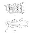
- FIG. 1is a side view of an illustrative light fixture in accordance with some embodiments of the invention.
- FIG. 2is a side view of a shaped light fixture in accordance with some embodiments of the invention.
- FIG. 3is a diagram of a radiation pattern provided by a shaped LGA having an integrated CPC reflector in accordance with some embodiments of the invention.
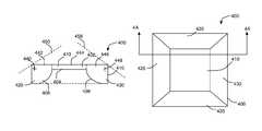
- FIG. 4Ais a sectional view of an illustrative LGA having a CPC reflector forming a secondary reflective surface in accordance with some embodiments of the invention
- FIG. 4Bis a top view of the illustrative LGA of FIG. 4A in accordance with some embodiments of the invention.
- FIG. 5Ais top view of an illustrative LGA in accordance with some embodiments of the invention.
- FIG. 5Bis a detailed view of a portion of the LGA of FIG. 5A in accordance with some embodiments of the invention.
- FIG. 6is a flow chart of an illustrative process for constructing a light guide array having a CPC reflector in accordance with some embodiments of the invention.
- an edge-lit LED light fixturehaving an elongated light guide array (LGA) to which a LED light source is coupled at a first end.
- the LGAcan be curved such that a surface of the LGA extends over several planes.
- the LGAcan include a CPC reflector for further changing an orientation at which light is emitted by the LGA.
- a light fixture that uses a LED module as a light sourcecan be mounted in several different manners.
- a light fixturecan be mounted to a ceiling, mounted under a counter, as part of a desk light, as a wall sconce, as a wall wash, as a surface mounted light fixture, or combinations of these.
- Light emitted by the LED modulecan be directed into the environment from the fixture by a light guide array (LGA).
- FIG. 1is a side view of an illustrative light fixture in accordance with some embodiments of the invention.
- Fixture 100can include LED module 102 providing light from light emitting surface 104 .
- Emitted light 105propagates through light guide array 110 (LGA 110 ) positioned adjacent to LED module 102 .
- LGA 110can include an extended structure defined such that light provided into the LGA is directed into the environment through one surface of the LGA.
- LGA 110can include an elongated body such that light is directed out of top boundary 116 of LGA 110 , but not out of bottom boundary 118 of LGA 110 .
- LED module 102can provide light to LGA 110 using different approaches.
- LED module 102may be placed in contact with or adjacent to first end 112 of LGA 110 such that light enters LGA 110 from first end 112 and is propagated towards second end 114 .
- Light 105 entering LGA 110can be reflected (e.g., totally internally reflected) in part by upper boundary 116 and lower boundary 118 .
- reflective component 120e.g., a separate reflective element offset from lower boundary 118
- portions 106 of light 105may be frustrated by ribs or other features incorporated in LGA 110 , such that portions 106 of light 105 leave LGA 110 through upper boundary 116 . These portions 106 may serve to illuminate the environment in which fixture 100 is placed. Portions 106 can exit LGA 110 at any angle relative to axis 130 of LED module 102 including, for example, at an angle substantially perpendicular to axis 130 . In some cases, however, the angle may be determined from features within LGA 110 for frustrating light, from the material of LGA 110 , or combinations of these.
- LGA 110can include any suitable waveguide for guiding light waves from a source into an environment.
- LGA 110can include a slab or planar waveguide, a rib waveguide, or any other type of waveguide.
- LGA 110can include several guides combining to redirect light from a LED module.
- LGA 110can have any suitable size or shape. In some cases, the size and shape used for a particular
- LGA 110can vary based on the desired use of a light fixture.
- LGA 110can substantially define a rectangular prism having sides that are constrained within planes. Adjacent sides of the LGA can be provided at substantially right angles.
- the rectangular prismcan have any suitable dimensions including, for example, a height of 150 mm (e.g., 6′′), a width of 5 mm (e.g., 0.2′′) and a length in the range of 300 mm to 2500 mm (e.g., 1′ to 8′).
- LGA 110can include a non-rectangular three-dimensional shape.
- LGA 110can include a triangular prism, or any other non-rectangular polygonal prism.
- FIG. 2is a side view of a shaped light fixture in accordance with some embodiments of the invention.
- Light fixture 200can include LED module 202 and LGA 210 having some or all of the features of light fixture 100 ( FIG. 1 ).
- LGA 210can include a base structure having first end 212 adjacent to source 204 of LED module 202 , upper boundary 216 through which light may escape LGA 210 , and lower boundary 218 adjacent to which reflecting component 220 is placed.
- LGA 210may define curved boundary 216 , such that light 206 frustrated by features (eg, ribs) on LGA 210 is emitted at different angles relative to axis 230 of LED module 202 .
- the shape of LGA 210can be customized for a particular environment, such that the distribution and angles of light 206 corresponds to different regions of the environment.
- the shape of LGA 210can be defined as a spline that is projected along a vector to create a surface.
- spline 232can be projected along axis 234 to create a surface at boundary 216 of LGA 210 .
- upper boundary 216 and lower boundary 218may be substantially parallel to provide boundaries for rays that are not frustrated by surface features of LGA 210 .
- the LGAcan include a surface corresponding to a CPC reflector in some regions of the LGA.
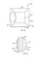
- FIG. 3is a diagram of a radiation pattern provided by a shaped LGA having an integrated CPC reflector in accordance with some embodiments of the invention.
- Pattern 300can include several lobes 310 , 320 and 330 extending at different angles relative to axes 302 and 304 , where axis 302 is within the plane of the LGA, and axis 304 is perpendicular to the plane of the LGA and directed towards the environment.
- Center lobe 310can extend substantially along axis 304 into the environment of the light fixture.
- light corresponding to center lobe 310can be provided by a primary surface of the LGA (e.g., a surface that does not correspond to a CPC reflector).
- Lobe 310can correspond to any suitable type of radiation including, for example, Lambertian radiation generated by the LGA.
- Side lobes 320 and 330can extend at angles relative to axis 302 .
- side lobe 320can be defined such that side lobe 320 extends between axis 302 and cut-off axis 306 a , which is angled at angle 308 a relative to axis 302 .
- side lobe 330can be defined such that side lobe 330 extends between axis 302 and cut-off axis 306 b , which is angled at angle 308 b relative to axis 302 .
- Angles 308 a and 308 bcan be the same or different, for example based on the environment in which the LGA is placed.
- angles 308 a and 308 bcan be determined from attributes of CPC reflectors providing secondary surfaces reflecting LGA flux. Angles 308 a and 308 b can serve as cut-off angles changing the orientation at which the LGA illuminates an environment. In particular, the flux can be steered to elevations between axis 302 and cut-off axes 306 a and 306 b . This may improve the off-axis illumination of the LGA.
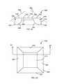
- FIG. 4Ais a sectional view of an illustrative LGA having a CPC reflector forming a secondary reflective surface in accordance with some embodiments of the invention.
- FIG. 4Bis a top view of the illustrative LGA of FIG. 4A in accordance with some embodiments of the invention.
- LGA 400can include base 402 having central section 410 defining primary surface 404 of the LGA.
- CPC reflectors 420 , 425 , 430 and 435can be distributed around periphery 406 of base 402 (e.g., forming a closed loop of CPC reflectors). Each reflector can define a shape of a partial parabola angled relative to primary surface 404 .
- each reflectorcan define a secondary reflective surface for redirecting a beam to off-axis elevations and azimuths, as determined from the angle of the reflector relative to a plane of the primary light source.
- each reflectorcan instead replace a parabolic section with a hyperbolic section combined with a collimating lens.
- each reflectorcan be defined by an origin (e.g., points 440 and 448 ), an axis (e.g., axes 450 and 458 ), and a width.
- the parabolascan be defined such that the origins fall within LGA 400 , along an edge of LGA 400 (e.g., on periphery 406 or along an edge of LGA 400 ), or outside of LGA 400 .
- a reflectorcan be shaped such that the origin is at an edge or within the LGA.
- light frustrated at the origincan be directed substantially entirely by the CPC reflector (e.g., by reflector 420 or 430 , respectively) at an off-axis elevation (e.g., corresponding to side lobes 320 and 330 , FIG. 3 ).
- Light frustrated in region 444 of LGA 400 between reflectorscan be directed in a direction substantially normal to primary surface 404 (e.g., corresponding to primary lobe 310 , FIG. 3 ).
- Light frustrated by region 442 of LGA 400 that is between point 440 and region 444can be partially reflected by secondary surface 408 corresponding to reflector 420 , and the remainder transmitted without reflecting, contributing to node 310 in FIG. 3 .
- light frustrated by region 446 of LGA 400 that is between point 448 and region 444can be partially reflected by secondary surface 409 corresponding to reflector 430 and the remainder transmitted with reflecting, contributing to node 310 in FIG. 3 .
- light emitted by portions of primary surface 404 that are underneath a reflectormay be redirected by the secondary surface at an angle that is bound by a sharp cut-off at an angle or elevation corresponding to the CPC reflector.
- This approachmay allow precise control of the flux and beam shaping for modest to extreme off-axis elevations and azimuths.
- the size and position of the reflectors relative to the primary surface within the reflectorscan be tuned for performance in a particular environment. For example, by extending the reflector in-board from the periphery of the LGA, more of the flux can be captured and redirected off-axis. Alternatively, if the reflector is moved out-board towards the periphery of the LGA, less flux may be captured by the reflector and the LGA may provide a more direct light along an axis of the LGA.
- the base or reflectors of LGA 400can include internal features for frustrating light out of the LGA and into the environment.
- the LGAcan include several ribs distributed within the LGA at various intervals for frustrating light.
- FIG. 5Ais top view of an illustrative LGA in accordance with some embodiments of the invention.
- FIG. 5Bis a detailed view of a portion of the LGA of FIG. 5A in accordance with some embodiments of the invention.
- LGA 500can include base 510 and CPC reflectors 520 , 525 , 530 and 535 disposed around periphery 506 of LGA 500 .
- Portion 540 of LGA 500shown in FIG. 5B , can include a portion of reflector 520 and a portion of base 510 .
- Each of reflector 520 and base 510can include features for frustrating light emitted by a light source.
- the featurescan correspond to ribs extending along a length of reflector 520 and base 510 .
- reflector 520can include ribs 550
- base 510can include ribs 552 . Based on the frequency or density of ribs, the amount of light frustrated by each portion of LGA 500 can vary.
- the number or density of ribs in each portioncan be tuned.
- ribs 550 and ribs 552can be distributed at intervals varied to provide similar light outputs by each of reflector 520 and base 510 .
- ribs 550 and ribs 552can be distributed at different intervals (e.g., such that ribs 550 are closer to each other than ribs 552 , or vice versa) to direct more or less light out of reflector 520 relative to base 510 .
- the space between adjacent ribs in one or both of base 510 and reflector 520can vary.
- the distance between ribs 550may increase from outer boundary 522 of reflector 520 towards interface 524 between reflector 520 and base 510 .
- the distance between ribs 522 in base 510can increase from interface 524 towards a center of base 510 . This approach can ensure that light is evenly distributed in each of the lobes depicted in light pattern 300 ( FIG. 3 ).
- a LGA having a curved surface and a CPC reflectorcan be constructed using different approaches.
- different features of the LGAcan be cut from a block of material (e.g., using a machining process).
- the LGAcan be molded (e.g., injection molded, compression molded, or vaccum formed) with desired features.
- one or more surfaces of the LGAcan be processed to improve their reflectivity.
- the surfaces of the LGAcan be polished (e.g., using an abrasive tool).
- the LGAcan be constructed from any suitable material.
- the material usedcan be selected such that the index of refraction between the material and air is approximately 1.5.
- Such materialscan include, for example, an acrylic, polycarbonate, glass, or another plastic material that is substantially transparent.
- FIG. 6is a flow chart of an illustrative process for constructing a light guide array having a CPC reflector in accordance with some embodiments of the invention.
- Process 600can begin at step 602 .
- a shaped light guide arraycan be provided.
- an optically transparent materialcan be retrieved and shaped to fit in a light fixture.
- the materialcan be provided substantially as a rectangular prism that includes a curved surface.
- a secondary surface corresponding to a reflectorcan be defined on the light guide array.
- a parabolic shape corresponding to a CPC reflectorcan be defined in the LGA, where the axis of the parabolic shape can be selected to provide off-axis illumination using the light guide array.
- materialcan be cut away from a base structure to form the secondary surface.
- the light guide arraycan include any suitable number of secondary surfaces corresponding to reflectors including, for example, four secondary surfaces corresponding to four reflectors positioned around four sides of the LGA.
- the light guide arraycan be polished to improve the reflectivity of the light guide array.
- a diffusive layercan be placed over one or both of the primary surface and the secondary surface.
- other finishing processescan be applied to the LGA, or step 608 can be skipped. Process 600 can then end at step 610 .
Landscapes
- Physics & Mathematics (AREA)
- General Physics & Mathematics (AREA)
- Optics & Photonics (AREA)
- Planar Illumination Modules (AREA)
- Non-Portable Lighting Devices Or Systems Thereof (AREA)
Abstract
Description
Claims (20)
Priority Applications (2)
| Application Number | Priority Date | Filing Date | Title |
|---|---|---|---|
| US12/983,787US9103953B2 (en) | 2011-01-03 | 2011-01-03 | Off-axis illumination LED luminaire |
| PCT/US2012/020041WO2012094292A1 (en) | 2011-01-03 | 2012-01-03 | Off-axis illumination led luminaire |
Applications Claiming Priority (1)
| Application Number | Priority Date | Filing Date | Title |
|---|---|---|---|
| US12/983,787US9103953B2 (en) | 2011-01-03 | 2011-01-03 | Off-axis illumination LED luminaire |
Publications (2)
| Publication Number | Publication Date |
|---|---|
| US20120170260A1 US20120170260A1 (en) | 2012-07-05 |
| US9103953B2true US9103953B2 (en) | 2015-08-11 |
Family
ID=45582016
Family Applications (1)
| Application Number | Title | Priority Date | Filing Date |
|---|---|---|---|
| US12/983,787Expired - Fee RelatedUS9103953B2 (en) | 2011-01-03 | 2011-01-03 | Off-axis illumination LED luminaire |
Country Status (2)
| Country | Link |
|---|---|
| US (1) | US9103953B2 (en) |
| WO (1) | WO2012094292A1 (en) |
Cited By (9)
| Publication number | Priority date | Publication date | Assignee | Title |
|---|---|---|---|---|
| US10890300B2 (en) | 2015-03-10 | 2021-01-12 | Jiaxing Super Lighting Electric Appliance Co., Ltd. | LED tube lamp |
| US10989365B2 (en) | 2014-09-28 | 2021-04-27 | Jiaxing Super Lighting Electric Appliance Co., Ltd. | LED tube lamp for operating in different modes |
| US11112068B2 (en) | 2014-09-28 | 2021-09-07 | Jiaxing Super Lighting Electric Appliance Co., Ltd | LED tube lamp |
| US11131431B2 (en) | 2014-09-28 | 2021-09-28 | Jiaxing Super Lighting Electric Appliance Co., Ltd | LED tube lamp |
| US11441742B2 (en) | 2015-12-09 | 2022-09-13 | Jiaxing Super Lighting Electric Appliance Co., Ltd. | LED tube lamp |
| US11519565B2 (en) | 2015-03-10 | 2022-12-06 | Jiaxing Super Lighting Electric Appliance Co., Ltd | LED lamp and its power source module |
| US11543086B2 (en) | 2015-03-10 | 2023-01-03 | Jiaxing Super Lighting Electric Appliance Co., Ltd. | LED tube lamp |
| US11686457B2 (en) | 2014-09-28 | 2023-06-27 | Jiaxing Super Lighting Electric Appliance Co., Ltd | LED tube lamp |
| US12085263B2 (en) | 2014-09-28 | 2024-09-10 | Jiaxing Super Lighting Electric Appliance Co., Ltd | LED tube lamp |
Families Citing this family (14)
| Publication number | Priority date | Publication date | Assignee | Title |
|---|---|---|---|---|
| US9078305B2 (en) | 2009-12-16 | 2015-07-07 | Enlighted, Inc. | Distributed lighting control that includes satellite control units |
| US9081125B2 (en) | 2011-08-08 | 2015-07-14 | Quarkstar Llc | Illumination devices including multiple light emitting elements |
| US8573823B2 (en) | 2011-08-08 | 2013-11-05 | Quarkstar Llc | Solid-state luminaire |
| CN103858244B (en) | 2011-08-08 | 2018-08-10 | 夸克星有限责任公司 | Lighting device comprising a plurality of light emitting elements |
| EP2895794B1 (en) | 2012-09-13 | 2018-06-27 | Quarkstar LLC | Illumination systems providing direct and indirect illumination |
| WO2014043369A2 (en) | 2012-09-13 | 2014-03-20 | Quarkstar Llc | Devices for workspace illumination |
| EP2909531A1 (en) | 2012-10-19 | 2015-08-26 | 3M Innovative Properties Company | Illumination articles |
| US9206956B2 (en) | 2013-02-08 | 2015-12-08 | Quarkstar Llc | Illumination device providing direct and indirect illumination |
| WO2014172571A2 (en) | 2013-04-19 | 2014-10-23 | Quarkstar Llc | Illumination devices with adjustable optical elements |
| EP3422059B1 (en) | 2013-07-18 | 2025-09-03 | Quarkstar LLC | Illumination device in which source light injection is non-parallel to device's optical axis |
| CN105723150B (en) | 2013-09-17 | 2019-02-22 | 夸克星有限责任公司 | Light guide lighting fixture with light divergence modifier |
| US10061071B2 (en)* | 2015-01-22 | 2018-08-28 | Philips Lighting Holding B.V. | Panel luminaire |
| US11014118B2 (en)* | 2015-12-11 | 2021-05-25 | Vitro Flat Glass Llc | Float bath coating system |
| CN110457845B (en)* | 2019-08-16 | 2022-08-26 | 昆明理工大学 | Method for constructing circular tube type solar composite parabolic condenser surface shape mathematical model |
Citations (20)
| Publication number | Priority date | Publication date | Assignee | Title |
|---|---|---|---|---|
| US4017155A (en)* | 1973-09-07 | 1977-04-12 | Kabushiki Kaisha Daini Seikosha | Liquid crystal display device |
| US4105293A (en)* | 1976-08-25 | 1978-08-08 | Aizenberg Julian Borisovich | Lighting installation based on light guide |
| US5921652A (en)* | 1995-06-27 | 1999-07-13 | Lumitex, Inc. | Light emitting panel assemblies |
| US6332690B1 (en)* | 1997-10-22 | 2001-12-25 | Yazaki Corporation | Liquid crystal display with curved liquid crystal screen |
| US6350050B1 (en)* | 2000-04-28 | 2002-02-26 | Fiberstars Incorporated | Efficient fiberoptic directional lighting system |
| US6561665B1 (en)* | 2002-03-14 | 2003-05-13 | Kim In-Chul | Lighting signboard having a curved structure |
| US6796700B2 (en)* | 2002-02-02 | 2004-09-28 | Edward Robert Kraft | Flat panel luminaire with remote light source and hollow light pipe for back lit signage applications |
| US20050100288A1 (en)* | 2003-11-10 | 2005-05-12 | Sunplus Technology Co., Ltd. | Light guide module having embedded LED |
| US7134768B2 (en)* | 2004-01-13 | 2006-11-14 | Stanley Electric Co., Ltd. | LED lamp with light guide |
| US7188989B2 (en)* | 2002-12-20 | 2007-03-13 | Citizen Electronics Co., Ltd. | Light guide plate and support unit for the same |
| US20080260329A1 (en)* | 2007-04-20 | 2008-10-23 | 3M Innovative Properties Company | Lightguides having curved light injectors |
| US20100028991A1 (en)* | 2008-01-14 | 2010-02-04 | Mccall Joe | Asymmetric compound parabolic concentrator and related systems |
| US7682062B2 (en)* | 2004-09-09 | 2010-03-23 | Nanogate Advanced Materials Gmbh | Illuminating device |
| US20100195349A1 (en)* | 2007-07-05 | 2010-08-05 | I2Ic Corporation | Light Source of Varying Thickness |
| US20110007506A1 (en)* | 2008-04-11 | 2011-01-13 | Harison Toshiba Lighting Corp. | Lighting apparatus |
| US7878686B2 (en)* | 2005-10-31 | 2011-02-01 | Toyoda Gosei Co., Ltd. | Light emitting device having a plurality of stacked radiating plate members |
| US20120098794A1 (en)* | 2008-10-31 | 2012-04-26 | Rpo Pty Limited | Transmissive Body |
| US8292480B2 (en)* | 2008-07-10 | 2012-10-23 | Koito Manufacturing Co., Ltd. | Lamp including main reflector, sub-reflector and LED assembly |
| US8322902B2 (en)* | 2008-03-03 | 2012-12-04 | Valeo Vision | Optical system with main function for motor vehicle |
| US8430517B2 (en)* | 2009-12-17 | 2013-04-30 | The Swatch Group Research And Development Ltd | Device for collimating, making uniform and extracting light for lighting a display device |
Family Cites Families (6)
| Publication number | Priority date | Publication date | Assignee | Title |
|---|---|---|---|---|
| DE1472267A1 (en)* | 1965-06-16 | 1969-12-04 | Zeiss Carl Fa | Axially symmetrical light guide device |
| US4240692A (en)* | 1975-12-17 | 1980-12-23 | The University Of Chicago | Energy transmission |
| US5528720A (en)* | 1992-03-23 | 1996-06-18 | Minnesota Mining And Manufacturing Co. | Tapered multilayer luminaire devices |
| KR100519238B1 (en)* | 2003-02-04 | 2005-10-07 | 화우테크놀러지 주식회사 | A Light Guide Panel With Guided-light Parts |
| CN101668988B (en)* | 2007-07-27 | 2011-06-15 | 夏普株式会社 | Lighting device and liquid crystal display device |
| US20100315811A1 (en)* | 2009-06-10 | 2010-12-16 | Shih-Chou Chen | Curved light guiding illuminator |
- 2011
- 2011-01-03USUS12/983,787patent/US9103953B2/ennot_activeExpired - Fee Related
- 2012
- 2012-01-03WOPCT/US2012/020041patent/WO2012094292A1/enactiveApplication Filing
Patent Citations (20)
| Publication number | Priority date | Publication date | Assignee | Title |
|---|---|---|---|---|
| US4017155A (en)* | 1973-09-07 | 1977-04-12 | Kabushiki Kaisha Daini Seikosha | Liquid crystal display device |
| US4105293A (en)* | 1976-08-25 | 1978-08-08 | Aizenberg Julian Borisovich | Lighting installation based on light guide |
| US5921652A (en)* | 1995-06-27 | 1999-07-13 | Lumitex, Inc. | Light emitting panel assemblies |
| US6332690B1 (en)* | 1997-10-22 | 2001-12-25 | Yazaki Corporation | Liquid crystal display with curved liquid crystal screen |
| US6350050B1 (en)* | 2000-04-28 | 2002-02-26 | Fiberstars Incorporated | Efficient fiberoptic directional lighting system |
| US6796700B2 (en)* | 2002-02-02 | 2004-09-28 | Edward Robert Kraft | Flat panel luminaire with remote light source and hollow light pipe for back lit signage applications |
| US6561665B1 (en)* | 2002-03-14 | 2003-05-13 | Kim In-Chul | Lighting signboard having a curved structure |
| US7188989B2 (en)* | 2002-12-20 | 2007-03-13 | Citizen Electronics Co., Ltd. | Light guide plate and support unit for the same |
| US20050100288A1 (en)* | 2003-11-10 | 2005-05-12 | Sunplus Technology Co., Ltd. | Light guide module having embedded LED |
| US7134768B2 (en)* | 2004-01-13 | 2006-11-14 | Stanley Electric Co., Ltd. | LED lamp with light guide |
| US7682062B2 (en)* | 2004-09-09 | 2010-03-23 | Nanogate Advanced Materials Gmbh | Illuminating device |
| US7878686B2 (en)* | 2005-10-31 | 2011-02-01 | Toyoda Gosei Co., Ltd. | Light emitting device having a plurality of stacked radiating plate members |
| US20080260329A1 (en)* | 2007-04-20 | 2008-10-23 | 3M Innovative Properties Company | Lightguides having curved light injectors |
| US20100195349A1 (en)* | 2007-07-05 | 2010-08-05 | I2Ic Corporation | Light Source of Varying Thickness |
| US20100028991A1 (en)* | 2008-01-14 | 2010-02-04 | Mccall Joe | Asymmetric compound parabolic concentrator and related systems |
| US8322902B2 (en)* | 2008-03-03 | 2012-12-04 | Valeo Vision | Optical system with main function for motor vehicle |
| US20110007506A1 (en)* | 2008-04-11 | 2011-01-13 | Harison Toshiba Lighting Corp. | Lighting apparatus |
| US8292480B2 (en)* | 2008-07-10 | 2012-10-23 | Koito Manufacturing Co., Ltd. | Lamp including main reflector, sub-reflector and LED assembly |
| US20120098794A1 (en)* | 2008-10-31 | 2012-04-26 | Rpo Pty Limited | Transmissive Body |
| US8430517B2 (en)* | 2009-12-17 | 2013-04-30 | The Swatch Group Research And Development Ltd | Device for collimating, making uniform and extracting light for lighting a display device |
Cited By (16)
| Publication number | Priority date | Publication date | Assignee | Title |
|---|---|---|---|---|
| US11649934B2 (en) | 2014-09-28 | 2023-05-16 | Jiaxing Super Lighting Electric Appliance Co., Ltd | LED tube lamp |
| US10989365B2 (en) | 2014-09-28 | 2021-04-27 | Jiaxing Super Lighting Electric Appliance Co., Ltd. | LED tube lamp for operating in different modes |
| US11112068B2 (en) | 2014-09-28 | 2021-09-07 | Jiaxing Super Lighting Electric Appliance Co., Ltd | LED tube lamp |
| US11131431B2 (en) | 2014-09-28 | 2021-09-28 | Jiaxing Super Lighting Electric Appliance Co., Ltd | LED tube lamp |
| US12372209B2 (en) | 2014-09-28 | 2025-07-29 | Jiaxing Super Lighting Electric Appliance Co., Ltd | LED tube lamp |
| US12173855B2 (en) | 2014-09-28 | 2024-12-24 | Jiaxing Super Lighting Electric Appliance Co., Ltd | LED tube lamp |
| US12085263B2 (en) | 2014-09-28 | 2024-09-10 | Jiaxing Super Lighting Electric Appliance Co., Ltd | LED tube lamp |
| US11519567B2 (en) | 2014-09-28 | 2022-12-06 | Jiaxing Super Lighting Electric Appliance Co., Ltd | LED tube lamp |
| US11686457B2 (en) | 2014-09-28 | 2023-06-27 | Jiaxing Super Lighting Electric Appliance Co., Ltd | LED tube lamp |
| US11543086B2 (en) | 2015-03-10 | 2023-01-03 | Jiaxing Super Lighting Electric Appliance Co., Ltd. | LED tube lamp |
| US10890300B2 (en) | 2015-03-10 | 2021-01-12 | Jiaxing Super Lighting Electric Appliance Co., Ltd. | LED tube lamp |
| US11698170B2 (en) | 2015-03-10 | 2023-07-11 | Jiaxing Super Lighting Electric Appliance Co., Ltd. | LED tube lamp |
| US11841113B2 (en) | 2015-03-10 | 2023-12-12 | Jiaxing Super Lighting Electric Appliance Co., Ltd | LED lamp and its power source module |
| US11519565B2 (en) | 2015-03-10 | 2022-12-06 | Jiaxing Super Lighting Electric Appliance Co., Ltd | LED lamp and its power source module |
| US11226073B2 (en) | 2015-03-10 | 2022-01-18 | Jiaxing Super Lighting Electric Appliance Co., Ltd. | Led tube lamp |
| US11441742B2 (en) | 2015-12-09 | 2022-09-13 | Jiaxing Super Lighting Electric Appliance Co., Ltd. | LED tube lamp |
Also Published As
| Publication number | Publication date |
|---|---|
| US20120170260A1 (en) | 2012-07-05 |
| WO2012094292A1 (en) | 2012-07-12 |
Similar Documents
| Publication | Publication Date | Title |
|---|---|---|
| US9103953B2 (en) | Off-axis illumination LED luminaire | |
| US9234650B2 (en) | Asymmetric area lighting lens | |
| US10705284B2 (en) | Luminaire with luminaire module | |
| US10274160B2 (en) | Luminaire for emitting directional and non-directional light | |
| US20120155116A1 (en) | High efficiency edge-lit light fixture | |
| RU2475672C2 (en) | Compact optical system and lenses for producing uniform collimated light | |
| US8475011B2 (en) | Lens member and optical unit using said lens member | |
| US9689554B1 (en) | Asymmetric area lighting lens | |
| US20120039077A1 (en) | Area lighting devices and methods | |
| US9442241B2 (en) | Optics for illumination devices | |
| US20100085763A1 (en) | Lens for a light emitting diode and manufacturing method therefor | |
| US20090040770A1 (en) | Light Source Reflector | |
| US11553566B2 (en) | Luminaire for emitting directional and non-directional light | |
| EP2619501A2 (en) | Segmented spotlight having narrow beam size and high lumen output | |
| CN104235758B (en) | Lens, the light-guiding shade with the lens and the lighting device using the lens | |
| CN209801374U (en) | Polarizing lens with large deflection angle and lamp | |
| EP3735555B1 (en) | An optical device for modifying light distribution | |
| CN111664420A (en) | Lamp and lens thereof | |
| KR20160141243A (en) | Diffusion cover for lighting with reflector | |
| EP3963253B1 (en) | A light emitting device | |
| US11927340B2 (en) | Reflective device and light source module | |
| US20130114266A1 (en) | Reflective unit and light source module having the same | |
| JP2003346526A (en) | Light control element and illuminating device using the same | |
| CN104566212B (en) | lens | |
| EP2594978A1 (en) | Reflective unit and light source module having the same |
Legal Events
| Date | Code | Title | Description |
|---|---|---|---|
| AS | Assignment | Owner name:LUNERA LIGHTING INC., CALIFORNIA Free format text:ASSIGNMENT OF ASSIGNORS INTEREST;ASSIGNORS:GARDNER, ROBERT C.;LOWERY, CHRISTOPHER H.;SIGNING DATES FROM 20101231 TO 20110103;REEL/FRAME:025578/0268 | |
| AS | Assignment | Owner name:AGILITY CAPITAL II, LLC, CALIFORNIA Free format text:SECURITY AGREEMENT;ASSIGNOR:LUNERA LIGHTING, INC.;REEL/FRAME:028701/0838 Effective date:20120731 | |
| AS | Assignment | Owner name:OPUS BANK, CALIFORNIA Free format text:SECURITY AGREEMENT;ASSIGNOR:LUNERA LIGHTING, INC.;REEL/FRAME:030074/0827 Effective date:20130320 | |
| AS | Assignment | Owner name:OPUS BANK, CALIFORNIA Free format text:SECURITY INTEREST;ASSIGNOR:LUNERA LIGHTING, INC.;REEL/FRAME:035192/0415 Effective date:20150227 | |
| ZAAA | Notice of allowance and fees due | Free format text:ORIGINAL CODE: NOA | |
| ZAAB | Notice of allowance mailed | Free format text:ORIGINAL CODE: MN/=. | |
| STCF | Information on status: patent grant | Free format text:PATENTED CASE | |
| AS | Assignment | Owner name:OPUS BANK, CALIFORNIA Free format text:SECURITY INTEREST;ASSIGNOR:LUNERA LIGHTING, INC.;REEL/FRAME:041372/0546 Effective date:20170221 | |
| AS | Assignment | Owner name:SILICON VALLEY BANK, COLORADO Free format text:SECURITY INTEREST;ASSIGNOR:LUNERA LIGHTING, INC.;REEL/FRAME:042164/0553 Effective date:20170426 | |
| AS | Assignment | Owner name:MONTAGE CAPITAL II, L.P., CALIFORNIA Free format text:SECURITY INTEREST;ASSIGNOR:LUNERA LIGHTING, INC.;REEL/FRAME:042181/0459 Effective date:20170428 Owner name:LUNERA LIGHTING, INC., CALIFORNIA Free format text:RELEASE BY SECURED PARTY;ASSIGNOR:AGILITY CAPITAL II, LLC;REEL/FRAME:042186/0753 Effective date:20170428 | |
| AS | Assignment | Owner name:LUNERA LIGHTING, INC., CALIFORNIA Free format text:RELEASE BY SECURED PARTY;ASSIGNOR:MONTAGE CAPITAL II, L.P.;REEL/FRAME:048031/0987 Effective date:20190108 | |
| AS | Assignment | Owner name:LUNERA LIGHTING, INC., CALIFORNIA Free format text:RELEASE BY SECURED PARTY;ASSIGNOR:SILICON VALLEY BANK;REEL/FRAME:048141/0491 Effective date:20190124 | |
| AS | Assignment | Owner name:TYNAX INC., CALIFORNIA Free format text:ASSIGNMENT OF ASSIGNORS INTEREST;ASSIGNORS:TYNAX INC.;LUNERA LIGHTING INC.;REEL/FRAME:048303/0100 Effective date:20190118 | |
| FEPP | Fee payment procedure | Free format text:SURCHARGE FOR LATE PAYMENT, LARGE ENTITY (ORIGINAL EVENT CODE: M1554); ENTITY STATUS OF PATENT OWNER: LARGE ENTITY | |
| MAFP | Maintenance fee payment | Free format text:PAYMENT OF MAINTENANCE FEE, 4TH YEAR, LARGE ENTITY (ORIGINAL EVENT CODE: M1551); ENTITY STATUS OF PATENT OWNER: LARGE ENTITY Year of fee payment:4 | |
| AS | Assignment | Owner name:SIGNIFY HOLDING B.V., NETHERLANDS Free format text:CHANGE OF NAME;ASSIGNOR:PHILIPS LIGHTING HOLDING B.V.;REEL/FRAME:048879/0800 Effective date:20190201 Owner name:PHILIPS LIGHTING HOLDING B.V., NETHERLANDS Free format text:ASSIGNMENT OF ASSIGNORS INTEREST;ASSIGNOR:TYNAX INC;REEL/FRAME:048879/0813 Effective date:20190118 | |
| FEPP | Fee payment procedure | Free format text:MAINTENANCE FEE REMINDER MAILED (ORIGINAL EVENT CODE: REM.); ENTITY STATUS OF PATENT OWNER: LARGE ENTITY | |
| LAPS | Lapse for failure to pay maintenance fees | Free format text:PATENT EXPIRED FOR FAILURE TO PAY MAINTENANCE FEES (ORIGINAL EVENT CODE: EXP.); ENTITY STATUS OF PATENT OWNER: LARGE ENTITY | |
| STCH | Information on status: patent discontinuation | Free format text:PATENT EXPIRED DUE TO NONPAYMENT OF MAINTENANCE FEES UNDER 37 CFR 1.362 | |
| FP | Lapsed due to failure to pay maintenance fee | Effective date:20230811 |