US9103732B2 - User computer device with temperature sensing capabilities and method of operating same - Google Patents
User computer device with temperature sensing capabilities and method of operating sameDownload PDFInfo
- Publication number
- US9103732B2 US9103732B2US13/307,334US201113307334AUS9103732B2US 9103732 B2US9103732 B2US 9103732B2US 201113307334 AUS201113307334 AUS 201113307334AUS 9103732 B2US9103732 B2US 9103732B2
- Authority
- US
- United States
- Prior art keywords
- temperature
- computer device
- thermal energy
- user computer
- user interface
- Prior art date
- Legal status (The legal status is an assumption and is not a legal conclusion. Google has not performed a legal analysis and makes no representation as to the accuracy of the status listed.)
- Expired - Fee Related, expires
Links
Images


Classifications
- G—PHYSICS
- G01—MEASURING; TESTING
- G01K—MEASURING TEMPERATURE; MEASURING QUANTITY OF HEAT; THERMALLY-SENSITIVE ELEMENTS NOT OTHERWISE PROVIDED FOR
- G01K13/00—Thermometers specially adapted for specific purposes
- G—PHYSICS
- G01—MEASURING; TESTING
- G01K—MEASURING TEMPERATURE; MEASURING QUANTITY OF HEAT; THERMALLY-SENSITIVE ELEMENTS NOT OTHERWISE PROVIDED FOR
- G01K2213/00—Temperature mapping
- G—PHYSICS
- G06—COMPUTING OR CALCULATING; COUNTING
- G06F—ELECTRIC DIGITAL DATA PROCESSING
- G06F2203/00—Indexing scheme relating to G06F3/00 - G06F3/048
- G06F2203/041—Indexing scheme relating to G06F3/041 - G06F3/045
- G06F2203/04105—Pressure sensors for measuring the pressure or force exerted on the touch surface without providing the touch position
Definitions
- the present inventionrelates generally to user computer devices and, in particular, to a user computer device with a touchscreen having temperature sensing capabilities.
- Mobile devicessuch as cellular telephones, smart phones and other handheld or portable electronic devices such as personal digital assistants (PDAs), headsets, MP3players, etc. have become popular and ubiquitous.
- PDAspersonal digital assistants
- Such mobile devicesnow often include numerous different types of input devices and/or sensors that allow for the mobile device to sense/receive signals indicative of a variety of user commands and/or operational conditions.
- many mobile devicesnow include not merely buttons that can be pressed by a user, but also input devices such as touch sensitive screens or navigation devices.
- many mobile devicesnow include other sensors such as sensors that can detect incoming light signals such as infrared signals, as well as sensors that sense position or movement of the mobile device including, for example, accelerometers.
- the operational conditions or context of a mobile devicecan be of interest for a variety of reasons. Yet, despite the number of different types of input devices/sensors that are already implemented in conventional mobile devices, there still remain a variety of operational conditions that cannot be easily detected, or detected at all, by way of such existing input devices/sensors. Indeed, the use of conventional input devices/sensors can be impeded by particular circumstances so as to preclude accurate determinations regarding certain types of operational conditions.
- mobile device(s)could be developed that had improved capabilities in terms of detecting one or more mobile device operational conditions and providing support for such improved detection capabilities.
- FIG. 1is a block diagram of a user computer device in accordance with an embodiment of the present invention.
- FIG. 2is a cross-sectional side view of the user computer device of FIG. 1 in accordance with an embodiment of the present invention.
- FIG. 3is a block diagram of an exemplary user computer device in accordance with an embodiment of the present invention.
- FIG. 4is an electrical schematic diagram of the user computer device of FIG. 1 in accordance with an embodiment of the present invention.
- FIG. 5is a schematic diagram of an exemplary layout of multiple thermal energy emitter/detector devices of a temperature sensitive user interface associated with the touchscreen of the user computer device of FIG. 1 in accordance with an embodiment of the present invention.
- FIG. 6is an exemplary layout of the temperature sensitive user interface associated with a touchcreen of the user computer device of FIG. 1 in accordance with an embodiment of the present invention.
- FIGS. 7 and 8are front perspective views of two further exemplary layouts of the temperature sensitive user interface associated with the touchscreen of the user computer device of FIG. 1 in accordance with other embodiments of the present invention.
- FIG. 9is a logic flow diagram illustrating how physical images may be thermally generated and displayed on the temperature sensitive user interface of the user computer device of FIG. 1 in accordance with an embodiment of the present invention.
- FIGS. 10 and 11depict exemplary physical images that may be thermally generated and displayed on the temperature sensitive touchscreen of the user computer device of FIG. 1 in accordance with various embodiments of the present invention.
- FIGS. 12 and 13are block diagrams depicting a display of exemplary thermally generated physical images on the temperature sensitive touchscreen of the user computer device of FIG. 1 in accordance with various embodiments of the present invention.
- FIG. 14is a block diagram depicting a thermal transfer of a thermally generated physical image from the temperature sensitive touchscreen of the user computer device of FIG. 1 to a temperature sensitive touchscreen of another user computer device in accordance with an embodiment of the present invention.
- FIGS. 15 and 16are block diagrams depicting a thermal transfer of an exemplary thermally generated physical image from the temperature sensitive touchscreen of the user computer device of FIG. 1 to temperature sensitive paper in accordance with an embodiment of the present invention.
- FIG. 17is a logic flow diagram illustrating a thermal authentication by the user computer device of FIG. 1 in accordance with various embodiments of the present invention.
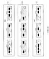
- FIG. 18is a block diagram illustrating multiple exemplary thermal authentication patterns that may be employed by the temperature sensitive user interface of the user computer device of FIG. 1 to perform thermal authentication in accordance with various embodiments of the present invention.
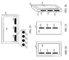
- FIG. 19is a front perspective view of a thermal energy docking station in accordance with an embodiment of the present invention.
- FIG. 20is a block diagram of the thermal energy docking station of FIG. 19 in accordance with an embodiment of the present invention.
- FIG. 21is an exemplary rear perspective view of the user computer device of FIG. 1 docked in the thermal energy docking station of FIG. 19 in accordance with an embodiment of the present invention.
- FIG. 22is an exemplary front perspective view of the user computer device of FIG. 1 docked in the thermal energy docking station of FIG. 19 in accordance with an embodiment of the present invention.
- FIGS. 23 to 26are block diagrams of the user computer device of FIG. 1 that illustrate exemplary distributions of multiple temperature sensing regions of the temperature sensitive user interface of the user computer device in accordance with various embodiments of the present invention.
- FIG. 27is a logic flow diagram illustrating thermal recognition of a docking station and user interface setting and control by the user computer device of FIG. 1 in accordance with various embodiments of the present invention.
- FIG. 28is a block diagram illustrating multiple exemplary thermal patterns that may be employed by the thermal energy docking station of FIG. 19 in accordance with various embodiments of the present invention.
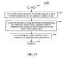
- FIG. 29is a logic flow diagram illustrating a pre-tuning of the temperature sensitive user interface of the user computer device of FIG. 1 in accordance with an embodiment of the present invention.
- a user computer devicesuch as a mobile device
- a temperature sensitive touchscreenhaving a temperature sensitive user interface comprising multiple thermal energy emitter/detector devices, such as thermocouples.
- the multiple thermal energy emitter/detector devicesare capable both of detecting thermal energy and generating thermal energy.
- the temperature sensitive user interfacegenerates thermal patterns that may be transferred to other thermally sensitive electronic devices or that may be used to authenticate the user computer device.
- the user computer devicealso can detect and thermally communicate with a thermal energy docking station and, based on thermal recognition, activate applications displayed on the temperature sensitive touchscreen. Further, the user computer device can auto-bias a temperature of the temperature sensitive user interface in order to better assure proper operation of the temperature sensitive user interface in all operating conditions.
- an embodiment of the present inventionencompasses a method for thermal information transfer by a user computer device comprising a housing and a temperature sensitive touchscreen having a plurality of thermal energy emitter/detector devices.
- the methodincludes determining a thermal pattern to be thermally transferred, activating one or more thermal energy emitter/detector devices, of the plurality of thermal energy emitter/detector devices, corresponding to the thermal pattern, producing, by the activated one or more thermal energy emitter/detector devices, the thermal pattern on one or more of the touchscreen and the houseing, and thermally transferring the produced thermal pattern to another temperature sensitive touchscreen.
- Another embodiment of the present inventioncomprises a method for thermal authentication of a user computer device.
- the methodincludes retrieving an authentication pattern to be thermally generated on a temperature sensitive touchscreen, activating, in a temperature sensitive user interface, only thermal energy emitter/detector devices corresponding to the authentication pattern, and thermally generating, by the activated thermal energy emitter/detector devices, the authentication pattern in the thermally sensitive touchscreen.
- Yet another embodiment of the present inventioncomprises a method for thermal recognition of an external accessory device that may be used in conjunction with a user computer device.
- the methodincludes detecting, by the user computer device, a thermal pattern that identifies the external accessory device, in response to detecting the thermal pattern and based on the detected thermal pattern, performing one or more of: activating, by the user computer device, an application corresponding to the detected thermal pattern adjusting, by the user computer device, an operational setting of the user computer device, such as brightness, volume, touch sensitivity, feature priority, and establishing a wireless connectivity, such as a Bluetooth or WiFi connectivity with a detected Bluetooth or WiFi device, based on the detected thermal pattern, and executing, by the user computer device, the one or more of the activated application, the adjusted setting, and the establishment of the wireless connectivity.
- Still another embodiment of the present inventioncomprises a method for biasing a temperature of a temperature sensitive user interface of a user computer device, the method including detecting one or more of a temperature of the user computer device and an ambient temperature, determining to pre-bias the temperature sensitive user interface based on the detected one or more temperatures, and, in response to determining to pre-bias the temperature sensitive user interface, auto-biasing a temperature of the temperature sensitive user interface.
- Yet another embodiment of the present inventionencompasses a user computer device that includes a housing, an at least one memory device that maintains at least one thermal pattern, a touchscreen comprising a temperature sensitive user interface having a plurality of thermal energy emitter/detector devices, and a processor coupled to the touchscreen and the at least one memory device and that is configured to determine to transfer a thermal pattern of the at least one thermal pattern and activate one or more thermal energy emitter/detector devices, of the plurality of plurality of thermal energy emitter/detector devices, corresponding to the thermal pattern, wherein the activated thermal energy emitter/detector devices produce the thermal pattern on one or more of the touchscreen and the housing.
- Still another embodiment of the present inventioncomprises a user computer device that includes an at least one memory device that maintains an authentication pattern, a touchscreen comprising a temperature sensitive user interface having a plurality of thermal energy emitter/detector devices, a processor coupled to the touchscreen and the at least one memory device and that is configured to retrieve the authentication pattern, activate, in the temperature sensitive user interface, only thermal energy emitter/detector devices corresponding to the authentication pattern, and wherein the activated thermal energy emitter/detector devices thermally generate the authentication pattern in the thermally sensitive touchscreen.
- Yet another embodiment of the present inventioncomprises a user computer device that is capable of thermally recognizing an external accessory device.
- the user computer devicecomprises a housing, an at least one memory device that maintains a thermal pattern that identifies the external accessory device, a temperature sensitive user interface having a plurality of thermal energy emitter/detector devices, and a processor that is coupled to the housing, the at least one memory device, and the temperature sensitive user interface and that is configured to detect, via the temperature sensitive user interface, the at least one thermal pattern that identifies the external accessory device, in response to detecting the thermal pattern and based on the detected thermal pattern, perform one or more of: activating an application corresponding to the detected thermal pattern, adjusting an operational setting of the user computer device, and establishing a wireless connectivity with the external accessory device, and execute the one or more of the activated application, the adjusted setting, or the establishment of the wireless connectivity.
- Still another embodiment of the present inventioncomprises an electronic device for thermally interfacing with a user computer device.
- the electronic deviceincludes a thermal energy interface that is configured to exchange thermal energy with the user computer device and a processor coupled to the thermal energy interface that is configured to one or more of generate a thermal pattern in the thermal energy interface that may be detected by the user computer device and detect a thermal pattern emitted by the user computer device.
- Still another embodiment of the present inventioncomprises a user computer device that auto-biases a temperature sensitive user interface.
- the a user computer deviceincludes a housing, a temperature sensitive user interface having a plurality of thermal energy devices that are configured to one or more of emit thermal energy and detect thermal energy, and a processor coupled to the temperature sensitive user interface that is configured to detect one or more of a temperature of the user computer device and an ambient temperature, determine to pre-bias the temperature sensitive user interface based on the detected one or more temperatures, and in response to determining to pre-bias the temperature sensitive user interface, based on the ambient temperature, auto-bias a temperature of the temperature sensitive user interface.
- FIG. 1is a block diagram of an exemplary user computer device 102 in accordance with an embodiment of the present invention.
- User computer device 102may be any user computer device that allows a user to input instructions to the device via a touchscreen 104 and, optionally, may be capable of sending and receiving communication signals on a wireless network.
- user computer device 102is a wireless mobile device, such as a cellular telephone, a radio telephone, a smart phone, or a personal digital assistant (PDA), a laptop computer or a tablet computer with radio frequency (RF) capabilities, or any other handheld or portable electronic device with a user interface comprising a touchscreen 104 that allows a user to input instructions into the user computer device; however, user computer device 102 may be any type of user computer device, such as a personal computer or a laptop or tablet computer without wireless capabilities, that has a user interface that includes a temperature sensitive touchscreen.
- User computer devicefurther comprises a housing 120 with a front side 122 that includes touchscreen 104 , side edges 124 , and a back side 126 .
- touchscreen 104is a ‘temperature sensitive’ touchscreen that includes a touchscreen panel 106 , typically an insulator such as glass or plastic, and a thermal interface, that is, a temperature sensitive user interface 108 .
- Temperature sensitive user interface 108includes thermal energy emitter/detector componentry that allows for detection of a temperature differential existing between different locations on temperature sensitive user interface 108 .
- the thermal energy emitter/detector componentrymore particularly includes multiple thermal energy emitter/detector devices 110 positioned proximate to, or embedded in, panel 106 of touchscreen 104 .
- each of thermal energy emitter/detector devices 110may, based on a detected thermal energy, generate electrical signals that are indicative of the temperatures detected at the thermal energy emitter/detector device.
- the multiple thermal energy emitter/detector devices 110also, or instead, may be capable of generating and emitting thermal energy, for example, in response to application of a voltage to the device, which emitted thermal energy may be sensed by a user of user computer device 102 or by an external accessory designed to do so, for example, other user computer devices, thermal sensitive paper, or a user computer device thermal docking station as described below.
- each thermal energy emitter/detector device 110may be a thermocouple junction capable of generating a voltage in response to detection, by the device, thermal energy and generating thermal energy in response to application, to the device, of a voltage.
- the user computer deviceBy virtue of processing performed by user computer device 102 utilizing the information communicated by way of thermal energy emitter/detector devices 110 , and more particularly, electrical signals generated by the thermal energy emitter/detector devices that reflect detected temperatures, the user computer device is able to sense a temperature differential existing between the temperatures sensed by different sensing devices (or different groups of sensing devices) which is indicative of a temperature differential existing between the locations of those different sensing devices (or groups of sensing devices). This temperature differential information then may used in combination with other information obtained via other types of sensors by user computer device 102 to determine/predict an operational condition or context of the user computer device.
- User computer device 102further may include a layer of thermally sensitive film or ink 112 proximate to temperature sensitive user interface 108 and thermal energy emitter/detector devices 110 .
- an activating of thermal energy emitter/detector devices 110causes the devices to generate thermal energy, in turn causing a heating up of the thermally sensitive film or ink 112 proximate to the heated up thermal energy emitter/detector devices, thereby producing an image and/or color change in the film or ink corresponding to the heated up devices, which image may be displayed to a user of the user computer device.
- temperature sensitive user interface 108need not be restricted to areas of user computer device 102 proximate to touchscreen 104 .
- housing 120also, or instead, may include the layer of thermally sensitive film or ink 112 , such as a thermochromic film.
- temperature sensitive user interface 108may be located proximate to any outer surface of user computer device 102 , that is, proximate to, or included in, any part of housing 120 .
- An activation of temperature sensitive user interface 108 , and in particular thermal energy emitter/detector devices 110 of the temperature sensitive user interface, proximate to any part of housing 120then may produce an image and/or color change in the thermally sensitive film or ink associated with the housing and corresponding to the heated up devices.
- Touchscreen 104further may include a touch-detecting non-temperature-based user interface 114 , such as a capacitive user interface, a resistive user interface, a pressure-sensitive user interface, an optical user interface, or any other user interface that may occur to one of ordinary skill in the art that detects a position of a user's touch on a basis other than temperature, and an active visual display user interface 116 that is implemented using any of multiple well-known backlit display technologies, such as but not limited to a liquid crystal display (LCD), a light emitting diode (LED) display, an organic LED (OLED) display, a plasma display, e-ink, or any other well-known backlit display technology, that displays visual images on touchscreen 104 to a user of the user computer device 102 .
- a touch-detecting non-temperature-based user interface 114such as a capacitive user interface, a resistive user interface, a pressure-sensitive user interface, an optical user interface, or any other user interface that may occur to one of ordinary skill
- FIG. 2the layers of user interfaces depicted in FIG. 2 are provided merely for the purpose of illustrating the principles of the present invention and are not intended to limit touchscreen 104 to the order depicted and that the layering may be in any order and/or may be intermixed.
- user computer device 102includes a processor 302 such as one or more microprocessors, microcontrollers, digital signal processors (DSPs), combinations thereof or such other devices known to those having ordinary skill in the art.
- processor 302such as one or more microprocessors, microcontrollers, digital signal processors (DSPs), combinations thereof or such other devices known to those having ordinary skill in the art.
- DSPsdigital signal processors
- the particular operations/functions of processor 302 , and respectively thus of user computer device 102are determined by an execution of software instructions and routines that are stored in an at least one memory device 304 associated with the processor, such as random access memory (RAM), dynamic random access memory (DRAM), and/or read only memory (ROM) or equivalents thereof, that store data and programs that may be executed by the corresponding processor.
- RAMrandom access memory
- DRAMdynamic random access memory
- ROMread only memory
- processor 302alternatively may be implemented in hardware, for example, integrated circuits (ICs), application specific integrated circuits (ASICs), a programmable logic device such as a PLD, PLA, FPGA or PAL, and the like, implemented in the user computer device. Based on the present disclosure, one skilled in the art will be readily capable of producing and implementing such software and/or hardware without undo experimentation. Unless otherwise indicated, the functions described herein as being performed by user computer device 102 are performed by processor 302 .
- At least one memory device 304further maintains multiple applications that may be executed by processor 302 , such as a calendar application, a navigational application, an email application, a music application, a video application, a video game application, and a social network application.
- At least one memory device 304may maintain, in association with each such application, a thermal pattern that identifies the application. By communicating the thermal pattern to the user communication device, a user or external device is able to instruct the user communication device to retrieve the associated application and to execute the retrieved application by processor 302 .
- User computer device 102further includes a user interface 308 and, optionally, one or more of a transceiver 310 , a location determination module 316 , and a wireline interface 320 , for example, a USB (Universal Serial Bus) port, that are each coupled to processor 302 .
- Transceiver 310includes at least one wireless receiver (not shown) and at least one wireless transmitter (not shown) for receiving and transmitting wireless signals, such a radio frequency (RF) signals and/or short-range signals such as Bluetooth signals.
- RFradio frequency
- Location determination module 316such as a GPS (Global Positioning Satellite) module comprising a GPS receiver, a module that determines a position based on triangulation of received WiFi or base station signals, or any other location positioning method/module known in the art, determines a geographical location of the user computer device.
- User interface 308includes a display screen that comprises ‘thermally sensitive’ touchscreen 104 , and further may include a keypad, buttons, a touch pad, a joystick, an additional display, or any other device useful for providing an interface between a user and an electronic device such as user computer device 102 .
- User computer device 102further includes a touchscreen driver 306 that is maintained in at least one memory device 304 and that is executed by processor 302 , and temperature sensors 312 and other sensors 314 , for example, an ambient light sensor, an accelerometer, a gyroscope, and any other sensor, and in particular operational setting sensor, known in the art that may be included in a user computer device, such as a handheld or portable electronic device, in communication with the processor.
- Processor 302detects images sensed by temperature sensitive user interface 108 and touch-detecting non-temperature-based interface 114 , and controls images displayed by the temperature sensitive user interface and by active visual display user interface 116 , based on programs and data associated with touchscreen driver 306 .
- the temperature sensors 312include thermal energy emitter/detector devices 110 .
- temperature sensors 312can include any arbitrary number of thermal energy emitter/detector devices, and the temperature sensors can include a variety of different types of thermal energy emitter/detector devices.
- the other sensors 314these can include any one or more of a variety of different types of sensors.
- the other sensors 314can include a capacitive touch sensor and/or a resistive touch sensor or any other type of touch-sensitive component that are included in touch-detecting non-temperature-based user interface 114 .
- User computer device 102also includes a power supply 318 , such as a power converter for interfacing with a power outlet or a limited life power supply such as a removable and/or rechargeable battery, for providing power to the other internal components 302 , 304 , 308 , 310 , 312 , 314 , and 316 of user computer device 102 .
- a power supply 318such as a power converter for interfacing with a power outlet or a limited life power supply such as a removable and/or rechargeable battery, for providing power to the other internal components 302 , 304 , 308 , 310 , 312 , 314 , and 316 of user computer device 102 .
- Touchscreen driver 306comprises data and programs that control an operation of touchscreen 104 , such as sensing a temperature change in temperature sensitive user interface 108 of the touchscreen and determining a location of a touch on the touchscreen, and that may reconfigure an operation of the touchscreen as described in greater detail below.
- touchscreen 104also may be a ‘capacitive’ touchscreen as is known in the art.
- touchscreen panel 106typically an insulator such as glass, may be coated, on an inner surface, with touch-detecting non-temperature-based user interface 114 comprising a transparent electrical conductor, such as indium tin oxide (ITO).
- ITOindium tin oxide
- touch-detecting non-temperature-based user interface 114may comprise a grid-type pattern of metallic electrodes that may be embedded in touchscreen panel 106 or etched in a conductor coupled to an inner surface of the touchscreen panel or printed on a carrier material, such as any of various known optically clear ITO coated transparent, conductive film products, for example, an ITO on a PET (polyethylene terephthalate) carrier (ITOPET).
- ITOoptically clear ITO coated transparent, conductive film products
- PETpolyethylene terephthalate
- the electrical conductoris, in turn, coupled processor 302 and is controlled by touchscreen driver 306 .
- an electrical conductorsuch as a human body or a capacitive stylus
- touchscreen 104is a temperature sensitive touchscreen, for example, as described in U.S. patent application Ser. No. 12/774,509, entitled “Mobile Device with Temperature Sensing Capability and Method of Operating Same,” and filed on May 5, 2010, and which description of a thermally sensitive mobile device touchscreen is hereby incorporated herein.
- Temperature sensitive user interface 108may be proximate to an inner surface of touchscreen panel 106 or may be embedded in the panel.
- the multiple thermal energy emitter/detector devices 110may be embedded in, or may be attached to on an inner surface of, the touchscreen panel.
- Thermal energy emitter/detector devices 110are devices that sense an applied temperature and output an indication of the sensed temperature, such as a thermocouple formed by a respective junction of first and second types of materials, for example, a Indium Tin Oxide (InSnO 4 ) ceramic material (ITO) and a Indium Tin Oxide Manganese ceramic material (ITO:Mn), and may be distributed throughout temperature sensitive user interface 108 , and correspondingly throughout touchscreen 104 (and in a different plane, that is, above or below, the capacitive user interface associate with the touchscreen, or may be intermixed with the capacitive user interface).
- a thermocoupleformed by a respective junction of first and second types of materials, for example, a Indium Tin Oxide (InSnO 4 ) ceramic material (ITO) and a Indium Tin Oxide Manganese ceramic material (ITO:Mn)
- ITOIndium Tin Oxide
- ITO:MnIndium Tin Oxide Manganese ceramic material
- Certain thermal energy emitter/detector devices 110may be linked to each other by a graphite strip or other thermally-conductive strip so as to maintain the thermal energy emitter/detector devices at a same or substantially a same temperature, which temperature may be set at a temperature level different from that of an item that will touch touchscreen 104 , such as an exposed finger, a gloved finger, or a stylus.
- Thermal energy emitter/detector devices 110also may be electrically connected in series to enhance touch sensitivity as well as to enable differential drive functionality. Junctions connected in series result in alternating junction polarities due to thermocouple conductor type order. Junctions in phase are grouped together for additive response and those with opposite polarities are separated and in some cases used to drive opposing device sides for differential response.
- opposing polarity junctionsare kept at a known and same temperature for reference and are enabled by applying a Graphite type material in their vicinity.
- touch sensitivityis enhanced.
- the voltages generated by the thermal energy emitter/detector devicesall tend to increase (or decrease) generally uniformly and tend to be additive, and the resulting output voltage experienced at terminals connected to the thermal energy emitter/detector devices (which voltage is, in turn, read by processor 302 implementing touchscreen driver 306 ) will be the sum of the contributions from those thermal energy emitter/detector devices.
- processor 302is able to determine a location of a touch based on temperature differentials.
- FIG. 4an electrical schematic diagram 400 is provided showing how signals from thermal energy emitter/detector devices 110 can be processed to derive a differential temperature signal, as well as how that differential temperature signal can be processed along with other signals from other supporting sensors 314 , in accordance with an embodiment of the present invention.
- two thermal energy emitter/detector devices 110(depicted in FIG. 4 as thermal energy emitter/detector devices 110 A and 110 B ) are coupled in series between an inverting input 452 and a non-inverting input 454 of an operational amplifier 456 .
- a first lead 412 of a first temperature sensing device 110 A of the two thermal energy emitter/detector devices 110 A and 110 Bis coupled to the inverting input 452
- a first lead 422 of a second temperature sensing device 110 B of the two thermal energy emitter/detector devices 110 A and 110 Bis coupled to the non-inverting input 454
- a second lead 414 of the first temperature sensing device 110 Ais coupled to a second lead 424 of the second temperature sensing device 110 B .
- operational amplifier 456In response to input signals, for example, voltage or current signals, generated by the first and second thermal energy emitter/detector devices (or groups of devices) 110 A , 110 B , operational amplifier 456 generates an output signal at output terminal 458 that is proportional to the differential between the two input signals and thus proportional to the difference in temperatures experienced by the two thermal energy emitter/detector devices 110 A , 110 B .
- the differential temperature output signal provided at output terminal 458is sent to processor 302 by way of a communication link 460 (although not shown, an analog-to-digital converter can be provided as part of communication link 460 between output terminal 458 and processor 302 so that the differential temperature output signal is in digital form when provided to processor 302 ).
- processor 302also receives one or more signals from one or more other sensors 314 , for example, by way of additional communication links 432 and 434 , respectively. It should be further noted that, while for simplicity of illustration, in FIG. 3 the temperature sensing circuitry depicted in FIG.
- processor 302can determine a variety of operational conditions/contexts as will be discussed in further detail below.
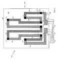
- FIG. 5a schematic diagram is provided of an exemplary layout of multiple thermal energy emitter/detector devices 110 as can be arranged on user computer device 102 in accordance with an embodiment of the present invention. As illustrated by FIG. 5 , each of multiple thermal energy emitter/detector devices 110 , depicted in FIG.
- thermal energy emitter/detector devices 110 1 - 110 8is a thermocouple formed by a respective junction of an ITO lead and an ITO:Mn lead, and these leads are all interconnected in a manner by which all of the thermal energy emitter/detector devices 110 1 - 110 8 are connected in series between a first terminal 550 and a second terminal 552 . Further as shown, the first and second terminals 550 and 552 respectively are coupled to respective copper wires 554 , 556 that are surrounded by a flexible plastic sheathe 558 so as to form a two-wire flex link.
- the copper wires 554 , 556 and sheathe 558extend away from the terminals 550 , 552 and allow those terminals to be coupled to other components (for example, to an operational amplifier that is, in turn, coupled to processor 302 ).
- the first terminal 550is linked to a first temperature sensing device 110 1 of the multiple thermal energy emitter/detector devices 110 1 - 110 8 by way of a first ITO lead 520 , and that temperature sensing device is, in turn, linked to a second temperature sensing device 110 2 of the multiple thermal energy emitter/detector devices 110 1 - 110 8 by way of a first ITO:Mn lead 530 .
- a second ITO lead 522extends from the second temperature sensing device 110 2 to a third temperature sensing device 110 3 the multiple thermal energy emitter/detector devices 110 1 - 110 8 , and a second ITO:Mn lead 532 links the third temperature sensing device 110 3 to a fourth temperature sensing device 110 4 of the multiple thermal energy emitter/detector devices 110 1 - 110 8 .
- a third ITO lead 524in turn links the fourth temperature sensing device 110 4 to a fifth temperature sensing device 110 5 of the multiple thermal energy emitter/detector devices 110 1 - 110 8 , which then is connected to a sixth temperature sensing device 110 6 of the multiple thermal energy emitter/detector devices 110 1 - 110 8 by way of a third ITO:Mn lead 534 .
- the sixth temperature sensing device 110 6is, in turn, connected to a seventh temperature sensing device 110 7 of the multiple thermal energy emitter/detector devices 110 1 - 110 8 by way of a fourth ITO lead 526 .
- the seventh temperature sensing device 110 7is connected to an eighth temperature sensing device 110 8 by way of a fourth ITO:Mn lead 536 .
- the eighth temperature sensing device 110 8is linked, by way of a fifth ITO lead 528 , to the second terminal 552 , which is also an ITO lead.
- thermocouple-type thermal energy emitter/detector devices 110In implementing thermocouple-type thermal energy emitter/detector devices 110 , the manner in which each temperature sensing device 110 is interconnected with other components (and the correspondent polarity of the device relative to other components) often is of significance in implementing the temperature sensing device, particularly where multiple thermal energy emitter/detector devices of this type are connected in series. For example, in an embodiment in which there are two thermocouple-type thermal energy emitter/detector devices 110 that are interconnected as shown in FIG. 4 , it is typical that the respective polarities of the thermal energy emitter/detector devices/thermocouples will be oppositely-orientated so as to allow for differential temperature sensing.
- the embodiment of user computer device 102 depicted in FIG. 5is an exemplary embodiment in which multiple thermal energy emitter/detector devices 110 are distributed at three different general regions along an inner surface of touchscreen 104 of the user computer device. Notwithstanding the fact that more than two thermal energy emitter/detector devices 110 are employed and coupled together in series, it is possible to obtain meaningful temperature information because of the particular manner in which the thermal energy emitter/detector devices are interconnected. As will be noticed from FIG.
- each of the thermal energy emitter/detector devices 110 2 , 110 4 , 110 6 , and 110 8 that are located proximate a bottom edge 562 of touchscreen 104are formed by the intersection of a respective one of the ITO:Mn leads 530 , 532 , 534 , 536 extending away from the respective temperature sensing device generally upwardly (that is, towards a top edge 566 of user computer device 102 ) and a respective ITO lead 522 , 524 , 526 , 528 that extends away from each of those respective thermal energy emitter/detector devices also generally upwardly but to the right of the respective ITO lead for that temperature sensing device (except in the case of the eighth temperature sensing device 110 8 , from which the ITO lead 528 extends downwardly (that is, towards the bottom edge 562 of user computer device 102 )) and to the left.
- each of the first and seventh thermal energy emitter/detector devices 110 1 , 110 7 towards a midregion 564 of touchscreen 104is connected to a respective one of the ITO leads 520 , 526 extending away from that temperature sensing device generally downwardly and also to one of the ITO:Mn leads 530 , 536 extending generally downwardly and to the right of the respective ITO lead for that device (it is the same for the third and fifth thermal energy emitter/detector devices 110 3 , 110 5 near the top edge 566 of touchscreen 104 ).
- the second, fourth, sixth, and eighth thermal energy emitter/detector devices 110 2 , 110 4 , 110 6 , and 110 8all share a first polarity
- the first, third, fifth, and seventh thermal energy emitter/detector devices 110 1 , 110 3 , 110 5 , and 110 7all share a second polarity that is opposite the first polarity.
- the voltages generated by those respective thermal energy emitter/detector devicesall tend to increase (or decrease) generally uniformly and tend to be additive, and the resulting output voltage experienced at the terminals 550 and 552 will be the sum of the contributions from those four sensing devices.
- Such reinforcing behavior of the thermal energy emitter/detector devices 110 2 , 110 4 , 110 6 , and 110 8is particularly facilitated by the presence of the graphite strip 570 .
- the pairs of thermal energy emitter/detector devices 110 3 / 110 5 and 110 1 / 110 7 at those respective locationswill tend to generate voltages that are additive and reinforcing of one another, and the resulting output voltage experienced at the terminals 550 , 552 will be the sum of the contributions of any one or more of those thermal energy emitter/detector devices.
- FIG. 5is reflective of certain assumptions regarding the operation of user computer device 102 .
- the arrangement of the multiple thermal energy emitter/detector devices 110 1 - 110 8presumes that it is unlikely that a user will touch (that is, apply heat proximate to) both one or more of the thermal energy emitter/detector devices 110 2 , 110 4 , 110 6 , and 110 8 near the bottom edge 562 while at the same time touch one or more of the thermal energy emitter/detector devices 110 1 , 110 3 , 110 5 , and 110 7 at the midregion 564 or near the top edge 566 .
- thermal energy emitter/detector devicestypically a user will only touch one or more of the thermal energy emitter/detector devices near the bottom edge 562 or touch one or more of the other thermal energy emitter/detector devices 110 1 , 110 3 , 110 5 , and 110 7 , but not both.
- Such an assumptionis especially plausible if the placement of some of the thermal energy emitter/detector devices is at or proximate to a location on user computer device 102 at which heat is less likely to be applied (for example, near a microphone on a mobile device).
- FIG. 5additionally illustrates how, in some embodiments of the present invention, various advantages can be achieved by utilizing multiple thermal energy emitter/detector devices provided within a given region of touchscreen 104 rather than utilizing only a single temperature sensing device to sense a temperature at a given region of the touchscreen.
- FIG. 5shows that multiple thermal energy emitter/detector devices, such as the devices 110 2 , 110 4 , 110 6 , and 110 8 can be collectively employed, effectively as a single ‘group sensor,’ so as to sense the temperature within a given region of touchscreen 104 , that is, proximate the bottom edge 562 of the touchscreen.
- FIG. 5shows that multiple thermal energy emitter/detector devices, such as the devices 110 2 , 110 4 , 110 6 , and 110 8 can be collectively employed, effectively as a single ‘group sensor,’ so as to sense the temperature within a given region of touchscreen 104 , that is, proximate the bottom edge 562 of the touchscreen.
- the multiple thermal energy emitter/detector devices 110 1 , 110 3 , 110 5 , and 110 7can be collectively employed, again effectively as a group sensor (or as multiple group sensors each made up of two thermal energy emitter/detector devices), to sense the temperature(s) at either one or both of the midregion 564 and proximate the top edge 566 of touchscreen 104 .
- these thermal energy emitter/detector devicesoperate as group sensors, temperature changes occurring nearing any of the sensing devices of the group sensor are sensed quickly. This is in contrast to other embodiments where only a single temperature sensing device is present within a given region, such that temperature changes must be communicated to the location of that particular temperature sensing device before those changes are sensed.
- FIG. 5illustrates how in some operational conditions it is possible for a variety of different temperature conditions within a variety of different regions of the mobile device can be sensed simply by series-connecting any arbitrary number of thermal energy emitter/detector devices 110 and using the simple hardware shown in (or hardware similar to that shown in) FIG. 4 .
- temperature changes experienced proximate the bottom edge 562 of touchscreen 104will have twice the effect as temperature changes experienced merely within the midregion 564 of the touchscreen, since four of the thermal energy emitter/detector devices are located near the bottom edge 562 while only two of the thermal energy emitter/detector devices are located near the midregion 564 .
- the overall voltage signals produced by the series-connection of those thermal energy emitter/detector devicescan be interpreted to determine temperature changes occurring at (and temperature differentials occurring between) those numerous different regions of the touchscreen.
- thermal energy emitter/detector deviceswere located in a first region, for example, a 5 millimeter (mm) circle, and are connected in series, and a single thermal energy emitter/detector device was located in another, second region, for example, another 5 mm circle, and assuming that all of the thermal energy emitter/detector devices are referenced to a separate cold junction, then temperature changes occurring at the first region would have four times the impact upon the overall output voltage of the five series-connected thermal energy emitter/detector devices than temperature changes occurring in the second region, and thus the overall output voltage could be interpreted accordingly.
- first regionfor example, a 5 millimeter (mm) circle
- second regionfor example, another 5 mm circle
- thermal energy emitter/detector devices 110sets of multiple thermal energy emitter/detector devices 110 positioned proximate to different edges of the touchscreen can all be connected in series with one another.
- a set of thermal energy emitter/detector devices 110are intended to operate as a ‘group sensor’ associated with a particular region of the touchscreen, the proximity of those thermal energy emitter/detector devices with respect to one another can vary depending upon the embodiment.
- one or more thermal energy emitter/detector devices 110can serve as a touch sensor.
- thermal energy emitter/detector devices 110along sides edges 124 of user computer device 102 , it is then possible to determine which side, or region of a particular side, of the user computer device is warmer and then conclude that the warmer side, or region, is the side or region that the user is holding, or to detect the way user is holding the user computer device.
- sensed temperature informationcan be interpreted as an indication of keypad entries or other user input signals or instructions.
- a first set of thermal energy emitter/detector devices 110for example, 20 thermal energy emitter/detector devices, can be placed within a first region of touchcsreen 104 and serve as a first ‘button’ while a second set of thermal energy emitter/detector devices 110 different in number, for example, one device, can be placed in a second region and serve as a second ‘button.’
- the user computer devicethen can detect whether the first region or the second region is touched based upon whether a voltage signal that is detected is large, for example, from the 20 devices, due to heating of the first region from the user's finger, or small, for example, from the one device, due to heating of the second region from the user'
- thermal energy emitter/detector devices 110may be implemented so that thermocouple junctions are situated immediately along the exterior of the touchscreen (that is, the junctions just pierce out of the mobile device as “dots”). Such embodiments can provide even more rapid response times, in terms of how fast temperature changes are sensed, than embodiments where the thermocouple junctions are embedded within a touch screen (much less where the junctions are beneath overlying structures). In general, for quickest sensing/response times, it is desirable to minimize the distance between the thermocouple junction and the heat source.
- Temperature sensitive user interface 108includes a grid of multiple thermal energy emitter/detector devices 110 that are proximate to an inner surface of, or embedded in, touchscreen panel 106 and that are distributed across the touchscreen panel, coupled to processor 302 , and controlled by touchscreen driver 306 .
- Processor 302then may determine a location of a touch based on thermal detections at various thermal energy emitter/detector devices 110 in the temperature sensitive user interface as described in greater detail above.
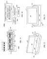
- FIGS. 6 and 7several examples of arrangements and configurations of thermal energy emitter/detector devices in user computer device 102 are shown in accordance with other embodiments of the present invention. It is to be understood, however, that these additional embodiments (as well as the embodiment shown in FIG. 6 ) are merely examples of the present invention, and that the present invention is intended to encompass numerous other arrangements and configurations not shown as well as those that are shown.
- user computer device 102may include a front logo region 704 as well as a rear logo region 706 (shown in phantom) respectively on a front side 122 and a back side 126 of the user computer device. It is at (or, more particularly, around and beneath/inwardly of the front logo region 704 and the rear logo region 706 , respectively, that front and rear thermal energy emitter/detector devices 110 (depicted in FIG. 7 as thermal energy emitter/detector devices 708 and 714 , respectively) are placed.
- each of the front temperature sensing device 708 and the rear temperature sensing device 714are looped structures that, as discussed in further detail below, in particular include thermocouple junctions that allow for temperature sensing to be accomplished.
- the respective thermal energy emitter/detector devicessense the temperatures along the logo regions due to thermal conduction through those regions.
- thermocouple junctions of the thermal energy emitter/detector devices 708 , 714can help to assure user contact with the thermal energy emitter/detector devices due to the logo large size.
- First and second leads 710 and 712 of first temperature sensing device 708can be considered analogous to leads 412 and 414 , respectively, of FIG. 4
- leads 716 and 718 of the second temperature sensing device 714can be considered analogous to the first and second leads 424 and 422 , respectively, of FIG. 4
- further componentssuch as the operational amplifier 456 of FIG. 4 are not shown in FIG. 7 , it can be presumed that thermal energy emitter/detector devices 708 and 714 can be operated and provide signals that are utilized in the same or substantially the same manner as was described with respect to FIG. 4 .
- the logo regions 704 , 706 of user computer device 102are shown to be positioned proximate an upper edge surface 124 of the user computer device, for example with the logo region 704 particularly being positioned in between the edge surface 124 and touchscreen 104 of the user computer device, it will be understood that the logo regions could be positioned at a variety of other locations along the front and back sides 122 , 126 of the user computer device, as well as on other surfaces (for example, the surfaces of side edge 124 or other edge/side surfaces) of the mobile device.
- the user computer devicemay include both a bezel 802 positioned along a front side 122 of user computer device 102 and a back plate 804 forming a surface of the back side 126 of the user computer device.
- bezel 802is a rectangular-shaped structure having an open interior 818 , that is, a shape similar to that of a picture frame.
- the user computer deviceincludes at least a first and a second temperature sensing device 110 (depicted in FIG. 8 as thermal energy emitter/detector devices 806 , 812 , respectively) that are positioned proximate the front and back sides 122 and 126 , respectively.
- the first temperature sensing device 806is positioned adjacent to the bezel 802 along the interior side of the bezel.
- the second temperature sensing device 812is positioned adjacent to the back plate 804 along the interior side of back plate 804 .
- the bezel 802 and back plate 804are heat conductive plates that are either directly exposed to the outside environment or embedded very close to the outer surface of the user computer device.
- Each of thermal energy emitter/detector devices 806 and 812includes a junction allowing for temperature sensing and includes a respective first lead 808 , 814 as well as a respective second lead 810 , 816 .
- the leads 808 , 814 of the thermal energy emitter/detector devicescan be understood to correspond to the leads 412 and 422 of FIG. 4
- the leads 810 , 816 of the thermal energy emitter/detector devicescan be understood to correspond to the leads 414 and 424 of FIG. 4 .
- thermal energy emitter/detector devices 806 and 812can be implemented in the same or substantially the same manner as discussed with reference to FIG. 4 . Given the positioning of the first temperature sensing device 806 along the interior surface of the bezel 802 , and given the positioning of the second temperature sensing device 812 along the interior surface of the back plate 804 , each of those respective thermal energy emitter/detector devices senses the temperature of a respective location exterior to the phone along the bezel 802 and back plate 804 , or radiates a temperature externally, by virtue of the conductive communication of heat through the bezel or the back plate, respectively. In the embodiments discussed above with respect to FIGS.
- user computer device 102as depicted therein has two thermal energy emitter/detector devices. Nonetheless, in a preferred embodiment of the present invention, user computer device 102 may have any number of interconnected thermal energy emitter/detector devices 110 . Indeed, depending upon the embodiment, user computer device 102 may have any arbitrary number of thermal energy emitter/detector devices 110 positioned on any one or more of the surfaces (and within any one or more regions along those surfaces), and those various thermal energy emitter/detector devices can be interconnected in any of a variety of manners.
- Temperature sensitive user interface 108 of user computer device 102can be used not only to detect a user input to the user computer device, that is, to detect a location of a user contact on a touchscreen such as touchscreen 104 , but also to provide thermal feedback. By providing thermal feedback, a variety of applications for user computer device 102 may be possible through an exchange of thermal energy with another temperature sensing device. For example, by selectively heating one or more thermal energy emitter/detector devices 110 of the user computer device, thermal-based authentication of the user computer device may be performed, information may be thermally transferred by the user computer device to another user computer device or to a thermally activated material (such as a thermal paper), or a color of a phone skin may be dynamically changed using thermochromic films or other methods. Also, temperature sensitive user interface 108 , and more particularly the thermal energy emitter/detector devices 110 of the temperature sensitive user interface, can sense external temperature and provide command to alter color of housing 120 to reflect the associated temperature.
- Logic flow diagram 900begins ( 902 ) when processor 302 determines ( 904 ) a physical image to be thermally generated by temperature sensitive user interface 108 of user computer device 102 from among one or more physical images maintained in at least one memory device 304 .
- the physical imagemay comprise a pattern, such as the various patterns depicted in FIG. 10 , may comprise a textual image, such as print characters of the signature depicted in FIG. 11 , or may comprise a color change.
- the physical image thermally generated on temperature sensitive user interface 108also may be displayed in touchscreen 104 or housing 120 by the thermally sensitive film or ink.
- the physical imagesmay be pre-programmed into user computer device 102 or may be downloaded, wirelessly or over a wired connection, by the user computer device from a physical image source, such as a web-based server or another user computer device.
- the physical imagesmay be transferred to, that is, received by, user computer device 102 from another user computer device, via touchscreen 104 and temperature sensitive user interface 108 of user computer device 102 , as described below with respect to FIG. 14 .
- the physical imagesmay be created on touchscreen 104 by a user of the user computer device and detected by temperature sensitive user interface 108 of the user computer device (for example, by taking a picture with a camera (not shown) by being sketched on touchscreen 104 by a user of the device).
- the user computer devicestores the received image in at least one memory device 304 .
- Processor 302may determine which physical image to generate based on an instruction received from a user of the user computer device 102 .
- processor 302may display, on touchscreen 104 , a softkey that is associated with the stored physical images. By touching the softkey, the user inputs to the processor, and the processor receives from the user, an instruction to display the patterns stored by the at least one memory device 304 .
- the instructionthat is, the user's touch of touchscreen 104 , may be received via temperature sensitive user interface 108 or via touch-detecting non-temperature-based user interface 114 .
- processor 302retrieves the physical images from the at least one memory device and displays the physical images on touchscreen 104 .
- the userthen may select a physical image by touching one of the displayed physical images, thereby inputting an instruction to the processor, via touch-detecting non-temperature-based user interface 114 , or temperature sensitive user interface 108 , to activate thermal energy emitter/detector devices 110 in temperature sensitive user interface 108 corresponding to the selected physical image.
- processor 302may determine a physical image to be thermally generated by temperature sensitive user interface 108 of user computer device 102 based on a user's touch of a physical image, such as an icon, displayed in the active visual display user interface 116 of by touchscreen 104 , such as an LCD or an LED display technology. That is, as is known in the art, when the active visual display user interface 116 displays a physical image on touchscreen 104 , processor 302 arranges for the image's display by arranging for illumination of appropriate image generating devices, for example, light emitting diodes or liquid crystals, that generate a predetermined image in a predetermined location on touchscreen 104 , which image and location are maintained in at least one memory device 304 . In turn, when a user touches such an image presented on the touchscreen, the user's touch of the image is relayed to the processor via touch-detecting non-temperature-based user interface 114 in accordance with well-known techniques.
- a physical imagesuch as an icon
- touchscreen 104such as an LCD or an LED display technology
- processor 302activates ( 906 ) thermal energy emitter/detector devices 110 corresponding to the determined image displayed in active visual display user interface 116 .
- processor 302may selectively apply a current or voltage to thermal energy emitter/detector devices 110 corresponding to the determined physical image.
- the selected thermal energy emitter/detector devicesthat is, thermal energy emitter/detector devices 110 to which current or voltage is selectively applied, activate, that is, heat up, thereby producing ( 908 ) a corresponding thermal image in temperature sensitive user interface 108 .
- the thermal imagemay or may not also be visually displayed on touchscreen 104 or housing 120 , for example, by a color or shade change in areas of the layer of thermally sensitive film or ink 112 proximate to the activated thermal energy emitter/detector devices. That is, the activating of the thermal energy emitter/detector devices may cause a heating up of the thermally sensitive film or ink 112 proximate to the selected thermal energy emitter/detector devices, which in turn may cause a corresponding color or shade change in the heated up areas of the thermally sensitive film or layer of thermally sensitive ink, thereby generating a color change/physical image that corresponds to the heated up devices, which color change/physical image may appear on touchscreen 104 or in housing 120 .
- FIGS. 12 and 13depict patterns that may appear on touchscreen 104 of user computer device 102 in response to processor 302 activating thermal energy emitter/detector devices corresponding to a physical image depicted in FIGS. 10 and 11 , respectively.
- user computer device 102may thermally transfer ( 910 ) the generated physical image, such as one of the physical images depicted in FIGS. 10 and 11 , to another thermally sensitive apparatus 1402 , such as another user computer device similar to user computer device 102 and that includes a temperature sensitive touchscreen 1404 similar to touchscreen 104 and having a temperature sensitive user interface 1408 similar to temperature sensitive user interface 108 of touchscreen 104 , a layer of thermally sensitive film or ink similar to the layer of thermally sensitive film or ink 112 , and that may further include one or more of a touch-detecting non-temperature-based user interface (not shown), similar to touch-detecting non-temperature-based user interface 114 , and an active visual display user interface (not shown), similar to active visual display user interface 116 .
- another thermally sensitive apparatus 1402such as another user computer device similar to user computer device 102 and that includes a temperature sensitive touchscreen 1404 similar to touchscreen 104 and having a temperature sensitive user interface 1408 similar to temperature sensitive user interface 108 of touchscreen 104 ,
- the user of user computer device 102then may place touchscreen 104 , which includes the thermally generated physical image, close enough to touchscreen 1404 that the heat generated by the activated thermal energy emitter/detector devices 110 of user of user computer device 102 and corresponding to the generated physical image is transferred to corresponding thermal energy emitter/detector devices of the temperature sensitive user interface 1408 of touchscreen 1404 .
- the thermal energy emitter/detector devices associated with touchscreen 1404 corresponding to the detected imageactivate, and thermally sensitive apparatus 1402 visually displays ( 912 ) the thermally transferred image on touchscreen 1404 .
- the activation of the thermal energy emitter/detector devices associated with touchscreen 1404may produce a corresponding color or shade change in areas of a thermally sensitive film 112 of touchscreen 1404 proximate to the thermal energy emitter/detector devices, resulting in a display of the thermally transferred image on touchscreen 1404 .
- the processor of thermally sensitive apparatus 1402may display the thermally transferred image on the active visual display user interface of touchscreen 1404 in accordance with well known techniques. Further, the processor of thermally sensitive apparatus 1402 may store ( 914 ) the thermally transferred image, that is, stores data associated with the corresponding activated thermal energy emitter/detector devices of user computer device 1402 , in an at least one memory device of user computer device 1402 . Logic flow 900 then ends ( 916 ).
- user computer device 102may transfer a thermally generated physical image to any thermally sensitive apparatus.
- the thermally generated physical image displayed on touchscreen 104 by user computer device 102may comprise any type of information that may be desired to be transferred to another device or to thermally sensitive material 1602 , such as thermally active paper.
- the physical image to be transferredmay be a textual pattern such as the receipt displayed on temperature sensitive user interface 108 of touchscreen 104 of user computer device 102 as depicted in FIG. 15 . This textual pattern then may be transferred to another user computer device, as depicted in FIG.
- thermally sensitive apparatussuch as thermally active paper 1602 as depicted in FIG. 16 , by placing touchscreen 104 of user computer device 102 close enough to thermally sensitive material 1602 that the heat generated by temperature sensitive user interface 108 , and in particular by the activated thermal energy emitter/detector devices 110 of user computer device 102 and corresponding to the generated physical image, is transferred to the thermally sensitive material.
- FIG. 14depicts user computer device 102 thermally transferring a thermal pattern to thermally sensitive apparatus 1402
- user computer device 102 and thermally sensitive apparatus 1402each may act as a conveyor of a thermally generated pattern as well as a recipient of a thermally generated pattern. That is, the another thermally sensitive apparatus 1402 , such as another user computer device, may, instead of or in addition to receiving a thermally generated pattern from user computer device 102 , thermally convey to user computer device 102 , and user computer device 102 may thermally receive from the another thermally sensitive apparatus, a thermal pattern as described above with reference to FIG. 9 .
- the another thermally sensitive apparatus 1402may be a user computer device similar to user computer device 102 that generates a thermal pattern in temperature sensitive user interface 1408 , or may be an electronic stamp that generates an electronic pattern having with a thermal imprint.
- User computer device 102then receives the thermal pattern, for example, the stamp pattern with respect to an electronic stamp, via touchscreen 104 and temperature sensitive user interface 108 and processor 302 may process the thermal pattern and/or processor 302 may store the received thermal pattern in at least one memory device 304 .
- the thermally generated pattern that is generated by user computer device 102may comprise authentication information that is used to authenticate the device.
- FIGS. 17 and 18a logic flow diagram 1700 is provided that illustrates a thermal authentication of user computer device 102 in accordance with various embodiments of the present invention.
- Logic flow diagram 1700begins ( 1702 ) when processor 302 of user computer device 102 determines ( 1704 ) to thermally authenticate user computer device 102 .
- a user of user computer device 102may input an authentication instruction, for example, by touching a corresponding icon of touchscreen 104 , or user computer device may self-determine to thermally authenticate itself based on a short-range (for example, Bluetooth, infra-red, near field communication (NFC), or thermally-generated) authentication request received from another electronic device or based on a context of the user computer device, for example, when the user computer device thermally detects a thermal energy detecting electronic device, such as detecting that it is docked in a thermal energy docking station as is described in greater detail below.
- a short-rangefor example, Bluetooth, infra-red, near field communication (NFC), or thermally-generated
- processor 302 of the user computer deviceIn response to determining to thermally authenticate user computer device 102 , processor 302 of the user computer device generates an thermal authentication pattern by retrieving ( 1706 ), from at least one memory device 304 of the user computer device, an authentication pattern to be thermally generated on touchscreen 104 of user computer device 102 and selectively activating ( 1708 ), in temperature sensitive user interface 108 , only the thermal energy emitter/detector devices 110 corresponding to the retrieved authentication pattern. For example, processor 302 may selectively apply a current or a voltage to thermal energy emitter/detector devices 110 corresponding to the thermal authentication pattern.
- the thermal energy emitter/detector devices 110 to which current or voltage is appliedactivate, that is, heat up, to generate ( 1710 ) the thermal authentication pattern, which then may be read ( 1712 ) by a thermal detecting device, such as another user computer device with a temperature sensitive touchscreen or any other kind of electronic device known to one of ordinary skill in the art that is capable of detecting a thermal pattern.
- a thermal detecting devicesuch as another user computer device with a temperature sensitive touchscreen or any other kind of electronic device known to one of ordinary skill in the art that is capable of detecting a thermal pattern.
- the thermal detecting devicethen authenticates ( 1714 ) user computer device 102 based on a recognition of the thermal authentication pattern, and logic flow 1700 then ends ( 1716 ).
- the thermal detecting devicemay maintain, in an at least one memory device of the thermal detecting device, thermal authentication patterns for all devices that have been properly registered with the thermal detecting device.
- the thermal detecting devicethat is, a processor of the thermal detecting device
- the processor of the thermal detecting devicecompares the read thermal authentication pattern to the thermal authentication patterns maintained in the at least one memory device of the thermal detecting device.
- the thermal detecting deviceauthenticates the user computer device.
- each authentication pattern 1801 - 1803comprises nine activated thermal energy emitter/detector devices 110 that are indicated by circles in touchscreen 104 of user computer device 102 ; however, one of ordinary skill in the art realizes that a thermal authentication pattern may comprise any number of activated thermal energy emitter/detector devices 110 .
- each thermal authentication pattern 1801 - 1803may comprise activated thermal energy emitter/detector devices 110 of multiple different temperatures, for example, a first, higher temperature indicated by the shaded thermal energy emitter/detector devices 110 of each thermal authentication patterns 1801 - 1803 and a second, lower temperature indicated by the unshaded thermal energy emitter/detector devices 110 of thermal authentication patterns 1801 - 1803 .
- such different temperature levelsmay be achieved by supplying different levels of current to the activated thermal energy emitter/detector devices 110 , wherein a larger current results in a higher temperature temperature sensing device. While each pattern depicted in FIG. 18 illustrates one or two temperature levels, one of ordinary skill in the art realizes that more than two temperature levels may be employed in a thermal authentication pattern.
- the thermal authentication pattern generated by processor 302may vary on a time scale.
- processor 302may activate one or more, but fewer than all, of the thermal energy emitter/detector devices 110 that are included in a pattern at any given time.
- processor 302may activate a first one or more thermal energy emitter/detector devices 110 of thermal authentication pattern 1801 during a first time period, a second one or more thermal energy emitter/detector devices 110 of the pattern during a second time period, wherein the first one or more thermal energy emitter/detector devices may be different from the second one or more thermal energy emitter/detector devices, a third one or more thermal energy emitter/detector devices 110 of the pattern during a third time period, wherein the third one or more thermal energy emitter/detector devices may be different from the first and second one or more thermal energy emitter/detector devices, and so on.
- processor 302may, instead of or in addition to the embodiment described above, activate a different number of thermal energy emitter/detector devices of thermal authentication pattern 1801 in each of multiple successive time periods.
- processor 302may activate a first number of thermal energy emitter/detector devices 110 , for example, two, of thermal authentication pattern 1801 in a first time period ‘t 1 ,’ activate a second number of thermal energy emitter/detector devices 110 , for example, three, of thermal authentication pattern 1801 in a second time period ‘t 2 ,’ and activate a third number of temperature sensing device 110 , for example, one, of thermal authentication pattern 1801 in a third time period ‘t 3 ,’ which two, three, and one thermal energy emitter/detector devices may or may not include one or more of the same thermal energy emitter/detector devices.
- processor 302may generate a different thermal authentication pattern in each of multiple successive time periods, for example, generating thermal authentication pattern 1801 at first time period ‘t 1 ,’ generating thermal authentication pattern 1802 at second time period ‘t 2 ,’ and generating thermal authentication pattern 1803 at third time period ‘t 3 .’
- the thermal authentication pattern generated by processor 302may be based on an operating context or external context of user computer device 102 , such as a purpose to which the device is being used or a location of the user computer device.
- the particular thermal authentication pattern, such as patterns 1801 - 1803 , retrieved and generated by processor 302may be based on a determination, by the processor, of an external context of the device, such as a determination, by the processor, of the user computer device's geographic location by reference to location determination module 316 or a receipt of short range signals, such as Bluetooth or infra-red signals, by the user computer device.
- the thermal authentication pattern generated by processor 302may be based on a determination, by the processor, of an application selected by a user of the user computer device as is known in the art. Processor 302 then may generate different thermal authentication patterns at different locations or in association with execution of different applications or in association with a different user logged into the device.
- user computer device 102By generating thermal patterns that may be thermally recognized by other electronic devices, user computer device 102 is able to provide for thermal pattern transfer, thereby provide for thermal recognition by other devices and providing thermal authentication, among other uses for thermal pattern recognition.
- user computer device 102is able to operate in contexts and operating conditions where the capabilities of user computer devices, such as a smart phone or a tablet computer, that have a touchscreen that is not a temperature sensitive touchscreen, are severely restricted, such as a winter environment when a user is outdoors and wearing gloves.
- user computer device 102is able to transfer that pattern merely by placing the touchscreen of the user computer device against a temperature sensitive touchscreen of another electronic device, thereby facilitating thermal transfer of information for a variety of consumer purposes, such as purchase payments, providing a copy of a consumer purchase receipt (for example, a street vendor or a farmer's market vendor will not have to provide paper receipts), coupon exchange, picture exchange, or using the user computer device as an electronic stamp.
- user computer device 102may operate as a ‘mood’ sensor, changing colors (by use of the layer of thermally sensitive film or ink 112 proximate to activated thermal energy emitter/detector devices) of touchscreen 104 (for example, a background displayed on touchscreen 104 ) or housing 120 based on a detected user or ambient temperature, and may even provide for color displays on touchscreen 104 that are activated and altered by sensed temperatures.
- user computer device 102also includes the capability of thermally detecting and recognizing an electronic accessory external to the user computer device, such as a user computer device docking station, and automatically making adjustments to user interface 308 and to execute applications in response to detecting the docking station.
- user computer device 102is able to use the thermal energy emitter/detector devices 110 of temperature sensitive user interface 108 to identify the accessory and/or accessory type, such as a docking station and/or a docking station-type, and in response, activate one or more applications and/or retrieve and display user-preferred settings associated with the identified accessory.
- Other user interface 308 settingssuch as display brightness, touchscreen sensitivity, sound volume, feature on/off, wireless connectivity, and so on, also may be adapted based on the identity of the docking station.
- FIGS. 19-28use of user computer device 102 in cooperation with a docking station is depicted in accordance with various embodiments of the present invention. While FIGS. 19-28 depict user computer device 102 interfacing with, that is, operating in cooperation with, a docking station, the docking station is provided as an example of any of multiple external electronic accessory devices, such as an email reader, a music player, a video player, a video game controller or a video game console, a social networking device, or any other electronic device that may occur to one skilled in the art that may thermally communicate with the user computer device.
- FIG. 19a front perspective view of a thermal energy docking station 1900 is depicted in accordance with an embodiment of the present invention.
- Thermal energy docking station 1900includes a thermal energy interface 1910 that is configured to exchange thermal energy with a user computer device, such as user computer device 102 , and more particularly that includes one or more thermal energy modules 1912 (three shown) that each may emit thermal energy that can be detected by the user computer device and/or may detect thermal energy emitted by the user computer device, for example, a thermal energy pattern generated by the thermal energy emitter/detector devices 110 of the user computer device.
- a thermal energy interface 1910that is configured to exchange thermal energy with a user computer device, such as user computer device 102 , and more particularly that includes one or more thermal energy modules 1912 (three shown) that each may emit thermal energy that can be detected by the user computer device and/or may detect thermal energy emitted by the user computer device, for example, a thermal energy pattern generated by the thermal energy emitter/detector devices 110 of the user computer device.
- Each thermal energy module 1912comprises one or more thermal energy emitter/detector devices 1914 that generate and emit, and/or detect, thermal energy that respectively can be sensed by, or generated by, thermal energy emitter/detector devices 110 of temperature sensitive user interface 108 of user computer device 102 (which temperature sensitive user interface, again, may be located near any external surface of the user computer device (for example, front side, back side, or sides of the device)). While FIG. 19 depicts four thermal energy emitter/detector devices 1914 per thermal energy generating module 1912 , one of ordinary skill in the art realizes that, depending upon the embodiment, each thermal energy module 1912 can include any arbitrary number of thermal energy emitter/detector devices 1914 .
- user computer device 102can determine that it is docked in docking station 1900 and further may detect a docking station-type and docking station functionality, and trigger execution of a specific application, such as a specific user interface display (UI), adjustment of a user computer device operational context, such as adjusting a brightness, adjusting a volume, turning features on/off, and so on, or establishment of a wireless connectivity with the external electronic accessory device via a short-range wireless protocol, such as the Bluetooth protocol or a Wireless Local Area Network (WLAN) protocol that operates in accordance with the IEEE (Institute of Electrical and Electronics Engineers) 802.xx standards, for example, the 802.11 or 802.16 standards.
- a specific applicationsuch as a specific user interface display (UI)
- UIuser interface display
- adjustment of a user computer device operational contextsuch as adjusting a brightness, adjusting a volume, turning features on/off, and so on
- a short-range wireless protocolsuch as the Bluetooth protocol or a Wireless Local Area Network (WLAN) protocol that operates in accordance
- thermal energy modules 1912may be distributed around thermal energy docking station 1900 in any manner so long as they are proximate to, and their generated thermal energy can be detected by, the thermal energy emitter/detector devices 110 of temperature sensitive user interface 108 of user computer device 102 .
- thermal energy docking station 1900comprises a bed in which user computer device 102 may be placed, that is, docked, which bed includes a bottom side 1904 atop a base 1902 of the docking station, two side walls 1906 , and a back side 1908 .
- FIG. 19further depicts multiple thermal energy generating modules 1912 (three shown) distributed across an inner side of the back 1908 of the bed of the thermal energy docking station.
- the thermal energy modules 1912may be located anywhere in the bed of thermal energy docking station 1900 , so long as the locations of the thermal energy modules 1912 are proximate to, and can be sensed by, thermal energy emitter/detector devices 110 of temperature sensitive user interface 108 of user computer device 102 .
- the docking station's thermal energy emitter/detector devices 1914not only generate recognition patterns and other information, but also may sense recognition patterns and other information from the user computer device, for example, generated by the temperature sensitive user interface 108 of the user computer device.
- the user computer devicecan provide instructions to the docking station (or accessory device) and vice versa.
- FIG. 20is a block diagram of thermal energy docking station 1900 in accordance with an embodiment of the present invention.
- Thermal energy docking station 1900includes a processor 2002 such as one or more microprocessors, microcontrollers, digital signal processors (DSPs), combinations thereof or such other devices known to those having ordinary skill in the art.
- the particular operations/functions of processor 2002and respectively thus of thermal energy docking station 1900 , are determined by an execution of software instructions and routines that are stored in a respective at least one memory device 2004 associated with the processor, such as random access memory (RAM), dynamic random access memory (DRAM), and/or read only memory (ROM) or equivalents thereof, that store data and programs that may be executed by the corresponding processor.
- RAMrandom access memory
- DRAMdynamic random access memory
- ROMread only memory
- At least one memory device 2004maintains a list of multiple applications that may be executed by a user computer device that can be docked in the thermal energy docking station, such as applications that may be stored in the at least one memory device 304 of, and executed by processor 302 of, user computer device 102 , for example, a calendar application, a navigational application, an email application, a music application, a video application, a video game application, and a social network application.
- the at least one memory device 2004further maintains, in association with each such application, a thermal pattern that identifies the application, which thermal identification patterns also are maintained, in association with each such application, in the at least one memory device of the dockable user computer device, that is, user computer device 102 .
- processor 2002alternatively may be implemented in hardware, for example, integrated circuits (ICs), application specific integrated circuits (ASICs), a programmable logic device such as a PLD, PLA, FPGA or PAL, and the like, implemented in the user computer device. Based on the present disclosure, one skilled in the art will be readily capable of producing and implementing such software and/or hardware without undo experimentation. Unless otherwise indicated, the functions described herein as being performed by thermal energy docking station 1900 are performed by processor 2002 .
- Thermal energy docking station 1900further includes thermal energy interface 1910 , having multiple thermal energy emitter/detector devices 1914 , in communication with processor 2002 .
- Each thermal energy emitter/detector device 1914may be any type of device that emits thermal energy when an electrical current is applied to the device and/or a voltage differential is applied across the device, or in other embodiments detects thermal energy emitted by an external thermal energy source, such as user computer device 102 .
- each thermal energy emitter/detector device 1914may comprise a resistor or a capacitor that output thermal energy in response to application of a current or a voltage differential, or may comprise a thermocouple, such as a thermocouple formed by a respective junction of first and second types of materials such as a Indium Tin Oxide (InSnO 4 ) ceramic material (ITO) and a Indium Tin Oxide Manganese ceramic material (ITO:Mn), that may emit or detect thermal energy.
- first and second types of materialssuch as a Indium Tin Oxide (InSnO 4 ) ceramic material (ITO) and a Indium Tin Oxide Manganese ceramic material (ITO:Mn)
- thermal energy emitter/detector devices 1914in a thermal energy generating module 1912 and/or by including multiple thermal energy generating modules 1912 in docking station 1900 , a variety of thermal energy patterns may be generated by the docking station, which allows user computer device 102 to detect a wider range of docking station types and docking station functions as well as to authenticate docking stations in order to access docking station functions.
- Thermal energy docking station 1900further includes a user interface 2006 that allows a user to interact with the docking station, for example, to input instructions into the docking station and to receive information from the docking station.
- user interface 2006may include a display screen 2102 , for example, included in a front side 1903 , an outside of a side wall 1906 , or the back side 1908 of the docking station (depicted, in FIG. 21 , as included in the back side 1908 ), for displaying information generated by processor 2002 , and may further include a mechanical control 2104 , such as a knob, lever or any other type of mechanical device that allows a user to input instructions into thermal energy docking station 1900 .
- a mechanical control 2104such as a knob, lever or any other type of mechanical device that allows a user to input instructions into thermal energy docking station 1900 .
- mechanical control 2104comprises a knob
- the user of the docking stationcan, by turning the knob, instruct the docking station to switch applications being implemented by the docking station.
- the application currently being implemented, and/or an application or menu of applications available for selection by the user of the docking station when operating mechanical control 2104may be indentified on display screen 2102 .
- Display screen 2102may be a liquid crystal display (LCD), a light emitting diode (LED) display, a plasma display, or any other means for visually displaying information, and further may be a touchscreen via which a user may input instructions into thermal energy docking station 1900 .
- LCDliquid crystal display
- LEDlight emitting diode
- plasma displayor any other means for visually displaying information
- itcan also be just control buttons w/o display.
- Thermal energy docking station 1900also includes a power source (not shown), such as a power converter that may be connected to a power outlet or a limited life power supply, such as a removable and/or rechargeable battery, for providing power to the other components of the thermal energy docking station.
- a power sourcesuch as a power converter that may be connected to a power outlet or a limited life power supply, such as a removable and/or rechargeable battery, for providing power to the other components of the thermal energy docking station.
- each temperature sensing region of the multiple temperature sensing regions 2302comprises one or more thermal energy emitter/detector devices 110 (four shown).
- Temperature sensing regions 2302may be distributed anywhere on user computer device 102 .
- the temperature sensing regions 2302may be distributed across front side 122 of the user computer device, for example, across touchscreen 104 as depicted in FIG.
- the temperature sensing regions 2302may be distributed across back side 126 of the user computer device as depicted in FIG. 25 , or the temperature sensing regions 2302 may be distributed across any side edge 124 of the user computer device as depicted in FIG. 26 .
- user computer device 102may detect thermal energy patterns generated by the docking station and process the detected patterns.
- FIGS. 21 and 22block diagrams are provided illustrating an exemplary placement of user computer device 102 in the bed of thermal energy docking station 1900 .
- FIG. 21is an exemplary rear perspective view of user computer device 102 docked in thermal energy docking station 1900
- FIG. 22is an exemplary front perspective view of the user computer device docked in the thermal energy docking station.
- the thermal energy generating modules 1912 of thermal energy docking station 1900are distributed across the inner side of the back 1908 of the bed of the thermal energy docking station, as depicted in FIG.
- the temperature sensing regions 2302 of user computer device 102be similarly distributed across back side 126 of the user computer device, for example, as depicted in FIG. 25 .
- the thermal energy generating modules 1912 of thermal energy docking station 1900are distributed across the bottom side 1904 of the bed of the thermal energy docking station, it may be preferable that the temperature sensing regions 2302 of user computer device 102 be similarly distributed across a side edge 124 of the user computer device, for example, as depicted in FIG. 26 .
- a logic flow diagram 2700is provided that illustrates a thermal recognition of thermal energy docking station 1900 , and a setting and control of user interface 308 , by user computer device 102 in accordance with various embodiments of the present invention.
- Logic flow diagram 2700begins ( 2702 ) when thermal energy docking station 1900 generates ( 2704 ) a first thermal pattern, that is, a thermal pattern that may be used to thermally identify the docking station. More particular, based on instructions and a thermal pattern maintained in at least one memory device 2004 of thermal energy docking station 1900 , processor 2002 activates one or more thermal energy output devices 1914 to generate the first thermal pattern.
- thermal energy docking station 1900When docked in thermal energy docking station 1900 , user computer device 102 , that is, processor 302 via temperature sensitive user interface 108 of the user computer device, thermally detects ( 2706 ) thermal energy docking station 1900 by detecting the first thermal pattern. More particularly, the thermal energy emitter/detector devices 110 of temperature sensitive user interface 108 of user computer device 102 detect the thermal pattern generated by the thermal energy emitter/detector devices 1914 of the thermal energy docking station.
- each thermal pattern 2801 - 2803comprises twelve activated thermal energy output devices 1914 . While six or seven activated thermal energy emitter/detector devices 1914 (indicated by the shaded thermal energy output devices) are depicted in each thermal pattern 2801 - 2803 shown in FIG. 28 , one of ordinary skill in the art realizes that a thermal pattern may comprise any number of activated thermal energy emitter/detector devices 1914 .
- each thermal pattern 2801 - 2803may comprise activated thermal energy emitter/detector devices 1914 of multiple different temperatures, for example, a first, higher temperature indicated by the shaded thermal energy emitter/detector devices 1914 of each thermal patterns 2801 - 2803 and a second, lower temperature indicated by the unshaded thermal energy emitter/detector devices 1914 of thermal patterns 2801 - 2803 .
- such different temperature levelsmay be achieved by supplying different levels of current to the thermal energy emitter/detector devices 1914 , wherein a larger current results in a higher temperature thermal energy emitter/detector device. While each pattern depicted in FIG. 28 illustrates one or two temperature levels, one of one of ordinary skill in the art realizes that more than two temperature levels may be employed in a thermal pattern.
- the thermal pattern generated by processor 2002may vary on a time scale.
- processor 2002may activate one or more, but fewer than all, of the thermal energy emitter/detector devices 1914 that are included in a pattern at any given time, for example, activating a different two or three of the thermal energy emitter/detector devices 1914 of thermal pattern 2801 at a time, as the processor cycles through the pattern.
- processor 2002may activate a different thermal energy generating module 1912 or a different number of thermal energy emitter/detector devices 1914 of thermal pattern 2801 in each of multiple successive time periods, for example, activating two of the thermal energy emitter/detector devices 1914 in a first time period, three of the thermal energy emitter/detector devices 1914 in a second time period, and activating a single thermal energy emitter/detector device 1914 in a third time period, which two, three, and one thermal energy emitter/detector devices may or may not include one or more of the same thermal energy emitter/detector devices.
- processor 2002may generate a different thermal pattern in each of multiple successive time periods, for example, generating thermal pattern 2801 at the first time period, generate thermal pattern 2802 at second time period, and generate thermal pattern 2803 at third time period.
- the thermal pattern generated by processor 2002may be based on an operating context of thermal energy docking station 1900 , such as an application being run on the docking station.
- the particular thermal pattern, such as patterns 2801 - 2803 , retrieved and generated by processor 2002may be based on a determination, by the processor, of an operating context of the docking station, such as a determination, by the processor, of an application selected by a user of the docking station as is known in the art.
- Processor 2002then may generate different thermal patterns in association with execution of different applications.
- user computer device 102activates ( 2708 ) a particular application, adjusts an operational setting of the user computer device, such as changing a display background or adjusting a brightness, a volume, a touch sensitivity, a feature priority, and/or establishes a wireless connectivity, such as a Bluetooth or WiFi connectivity with a detected Bluetooth or WiFi device and in accordance with well-known wireless connectivity establishment techniques, corresponding to the detected first thermal pattern and indicates ( 2710 ), for example, displays on touchscreen 104 , the activation of the application, the adjustment of the operational setting, and/or the establishment of the wireless connection.
- a wireless connectivitysuch as a Bluetooth or WiFi connectivity with a detected Bluetooth or WiFi device and in accordance with well-known wireless connectivity establishment techniques
- Logic flow 2700then ends ( 2712 ). That is, user computer device 102 may maintain, in the at least one memory device 304 of the user computer device, identifiers of multiple thermal patterns, for example, indicators of the thermal energy emitter/detector devices 110 that are activated in association with each such pattern, in association with corresponding applications.
- user computer device 102detects a thermal pattern, the user computer device compares the detected thermal pattern to the maintained thermal patterns, and when a match occurs then the user computer device determines, and activates, the associated application, brightness, volume, features on/off, wireless connectivity, etc.
- thermal energy docking station 1900is a calendar-based docking station
- user computer device 102in response to detecting the docking station, for example, detecting a thermal pattern identifying the docking station as a calendar-based docking station, user computer device 102 , and in particular processor 302 of the user computer device, may execute a time-and-date application maintained by at least one memory device 304 and may display, on touchscreen 104 , a current time of day and a current date.
- thermal energy docking station 1900is a navigational docking station
- user computer device 102in response to detecting the docking station, for example, detecting a thermal pattern identifying the docking station as a navigational docking station, user computer device 102 , and in particular processor 302 , may execute a navigational application maintained by at least one memory device 304 , for example, the GOOGLE® MAPS application provided by Google Inc., of Mountain View, Calif., or any other of many well-known navigational applications, and may display, on touchscreen 104 , a map that identifies a current location of the user computer device.
- a navigational applicationmaintained by at least one memory device 304 , for example, the GOOGLE® MAPS application provided by Google Inc., of Mountain View, Calif., or any other of many well-known navigational applications, and may display, on touchscreen 104 , a map that identifies a current location of the user computer device.
- thermal energy docking station 1900when thermal energy docking station 1900 supports multiple different applications for example, maintains thermal patterns associated with the multiple different applications, the thermal pattern generated by the docking station may be a thermal pattern corresponding to a particular application of the multiple different applications.
- thermal energy docking station 1900may support a calendar application, a navigational application, an email application, a social network application, such as the FACEBOOK® application provided by Facebook, Inc., of Palo Alto, Calif.
- a user of thermal energy docking station 1900may input to thermal energy docking station 1900 , and the thermal energy docking station may receive from the user, a selection of an application from among the multiple applications supported by the docking station.
- the usermay input his or her selection via user interface 2006 , for example, by selecting an application via mechanical control 2104 .
- thermal energy docking station 1900In response to receiving the selection from the user, thermal energy docking station 1900 generates a thermal pattern corresponding to the selected application, by activating thermal energy output devices 1914 corresponding to the thermal pattern.
- user computer device 102When docked in thermal energy docking station 1900 , user computer device 102 , and in particular processor 302 via temperature sensitive user interface 108 of the user computer device, thermally detects the selected thermal pattern generated by thermal energy docking station 1900 . More particularly, the thermal energy emitter/detector devices 110 of temperature sensitive user interface 108 of user computer device 102 detect the thermal pattern generated by the thermal energy thermal energy emitter/detector devices 1914 of the thermal energy docking station. Based on the thermal detection of the thermal pattern generated by thermal energy docking station 1900 , user computer device 102 then activates an application corresponding to the detected thermal pattern and displays the activated application on touchscreen 104 .
- a user of user computer device 102subsequently may change the application executed by the user computer device by changing the thermal pattern generated by thermal energy docking station 1900 . That is, subsequent to docking user computer device 102 in thermal energy docking station 1900 , the user may input to thermal energy docking station 190 , and the thermal energy docking station may receive ( 2714 ) from the user, a selection of a second application from among the multiple applications supported by the docking station. Again, the user may input the selection via user interface 2006 , for example, by selecting the second application via mechanical control 2104 .
- thermal energy docking station 1900In response to receiving the selection from the user, thermal energy docking station 1900 generates ( 2716 ) a thermal pattern corresponding to the second application by activating of thermal energy emitter/detector devices 1914 .
- User computer device 102and in particular processor 302 via temperature sensitive user interface 108 of the user computer device, thermally detects ( 2718 ) the second thermal pattern generated by thermal energy docking station 1900 . Based on the thermal detection of the second thermal pattern, corresponding to the second application, user computer device 102 then activates ( 2720 ) the second application, corresponding to the detected second thermal pattern, and displays ( 2722 ) the activated application on touchscreen 104 .
- Logic flow 2700then ends ( 2712 ).
- user computer device 102can execute, and display, a variety of applications merely by placing the user computer device in the docking station, without any need to plug the user computer device into the docking station or to connect any cables.
- the application displayed on the user computer device when docked in the docking stationmay be adjusting by merely inputting an instruction into the docking station, without the need to remove the user computer device from the docking station or the need to going through a variety of menus to find the desired application on the user computer device.
- a user of user computer device 102may use the user computer device in both indoor and outdoor environments and in all kinds of temperature conditions.
- user computer device 102may be operated in conditions where a user's temperature is very close to an ambient temperature of the environment in which the user computer device is operating or to an operating temperature of the device itself.
- the temperature of the thermal energy emitter/detector devices 110 of temperature sensitive user interface 108 of the user computer device 102may be close to a body temperature of the user, and more particularly to a temperature of the user's fingers, with the result that the temperature sensitive user interface may be unable to detect the user's touch.
- user computer device 102further provides for an auto-biasing, that is, a pre-tuning, of a temperature of the thermal energy emitter/detector devices 110 of temperature sensitive user interface 108 .
- a logic flow diagram 2900is provided that illustrates a pre-biasing of temperature sensitive user interface 108 of user computer device 102 , and in particular of the thermal energy emitter/detector devices 110 of the temperature sensitive user interface, in accordance with an embodiment of the present invention.
- Logic flow diagram 2900begins ( 2902 ) when user computer device 102 detects ( 2904 ) one or more of a temperature of user computer device 102 , such as a temperature of temperature sensitive user interface 108 and/or an operating temperature of the user computer device itself, and an ambient temperature, that is, a temperature of an environment in which the user computer device is operating.
- the ambient temperaturemay be a temperature of an immediate physical context of user computer device 102 , such as a temperature of a pocket or carrying bag, such as a purse, containing the user computer device, or may be a more remote physical context, such as an outdoor temperature of a geographical location in which a user of user computer device 102 is located, for example, an outdoor temperature in Chicago, Ill. or an indoor temperature of a building, or room in a building, in which the user is located.
- an immediate physical context of user computer device 102such as a temperature of a pocket or carrying bag, such as a purse, containing the user computer device
- a more remote physical contextsuch as an outdoor temperature of a geographical location in which a user of user computer device 102 is located, for example, an outdoor temperature in Chicago, Ill. or an indoor temperature of a building, or room in a building, in which the user is located.
- sensors 314 of user computer device 102may include a thermistor that detects an operating temperature of the user computer device and outputs a corresponding voltage to processor 302 in accordance with known techniques. Based on the level of the voltage, processor 302 is able to determine an operating temperature of the user computer device.
- sensors 314 of user computer device 102may include a temperature sensor, such as a thermometer, that measures an ambient temperature of the device, or user computer device 102 may execute an application maintained in the at least one memory device 304 and that uses a received broadcast of weather data to estimate the temperature corresponding to your GPS position, such as the ‘Thermometer’ from Mobiquite, of Niort, France, or weather applications available from WeatherBug®, from Earth Networks, of Germantown, Md., or The Weather Channel® of Cobb County, Ga., that provide for broadcast of local forecast and temperature information.
- a temperature sensorsuch as a thermometer
- user computer device 102determines ( 2906 ) to auto-bias, or pre-tune, a temperature of temperature sensitive user interface 108 .
- user computer device 102may maintain, in at least one memory device 304 , a pre-determined temperature range comprising one or more temperature thresholds, for example, a lower temperature threshold and an upper temperature threshold.
- a pre-determined temperature rangecomprising one or more temperature thresholds, for example, a lower temperature threshold and an upper temperature threshold.
- only a single thresholdmay be used, for example, to trigger auto-biasing when the detected temperature of user computer device 102 , such as of temperature sensitive user interface 108 , or the detected ambient temperature is below a first temperature threshold or above a second temperature threshold.
- User computer device 102then compares the detected temperature to the one or more temperature thresholds and determines whether to auto-bias, or pre-tune, temperature sensitive user interface 108 based on the comparison. For example, if the pre-determined temperature range is a temperature range centered at an average skin temperature, and the detected temperature is inside of the temperature range (for example, above a first, lower temperature threshold and below a second, higher temperature threshold), then user computer device 102 may determine to auto-bias, or pre-tune, temperature sensitive user interface 108 to a temperature outside of the range, for example, by adjusting a temperature of temperature sensitive user interface 108 either below the first temperature threshold or above the second temperature threshold.
- the pre-determined temperature rangeis a temperature range centered at an average skin temperature
- the detected temperatureis inside of the temperature range (for example, above a first, lower temperature threshold and below a second, higher temperature threshold)
- user computer device 102may determine to auto-bias, or pre-tune, temperature sensitive user interface 108 to a temperature outside of the
- a temperature differential between the detected temperature (which may be assumed to be an approximation of the temperature of the user computer device) and a user's touchcan more easily be detected.
- user computer devicemay determine not to auto-bias, or pre-tune, temperature sensitive user interface 108 .
- only a single thresholdmay be used, such as either the first, lower temperature threshold or the second, higher temperature threshold, and user computer device 102 may determine to auto-bias, or pre-tune, a temperature of temperature sensitive user interface 108 to a lower temperature when the detected temperature is above the first threshold or to a higher temperature when the detected temperature is below the second threshold.
- user computer device 102may determine to increase or to decrease a temperature of temperature sensitive user interface 108 based on a comparison of the two detected temperatures. For example, user computer device may determine a difference between the detected temperature of temperature sensitive user interface 108 and the detected ambient temperature. When the temperature difference is less than a temperature differential threshold, then user computer device 108 may determine to auto-bias, for example, to increase (or decrease) the temperature of temperature sensitive user interface 108 , that is, to adjust the temperature of temperature sensitive user interface 108 such that the difference between the temperature of the temperature sensitive user interface and the ambient temperature is greater than the temperature differential threshold. On the other hand, when the temperature difference is greater than the temperature differential threshold, then user computer device 108 may determine not to auto-bias the temperature of temperature sensitive user interface 108 .
- the user computer device 102determines to auto-bias, or pre-tune, temperature sensitive user interface 108 , the user computer device auto-biases ( 2908 ), that is, self-tunes, a temperature of the temperature sensitive user interface 108 , that is, adjusts a temperature of thermal energy emitter/detector devices 110 of temperature sensitive user interface 108 .
- user computer device 102may determine to adjust a temperature of the thermal energy emitter/detector devices to a pre-determined temperature level and/or elevate or decrease a temperature of the thermal energy emitter/detector devices by a predetermined amount, which predetermined amount may be based on the detected temperatures (for example, based on the amount of adjustment required to change the temperature of temperature sensitive user interface 108 to being above or below a temperature threshold or to produce a temperature differential between temperature sensitive user interface 108 and the ambient temperature that is greater than the temperature differential threshold).
- the temperature thresholdsas noted above, the temperature differential threshold, the pre-determined temperature level, and the predetermined amount may each be maintained in at least one memory device 304 of user computer device 102 .
- Logic flow 2900then ends ( 2910 ).
- user computer device 102may auto-bias one or more thermocouple junctions of temperature sensitive user interface 108 , or auto-bias a plate carrying the thermocouple junctions, by adjusting a temperature of the one or more thermocouple junctions or the plate to a temperature different from their current temperature, for example, such that a temperature of the thermocouple junctions is different from a user temperature.
- the auto-biasingcould be enabled by placing a heating element, such as a resistive element, for example, a resistor, near the thermocouple junction areas. Power (for example, an applied voltage or current) then could be continuously applied to the heating elements or could be applied in bursts in time (averaging effects) until the thermocouple junction temperatures are elevated by few degrees, for example, 5-10 degrees.
- the auto-biasing of the thermocouple junctions of temperature sensitive user interface 108could be generated in a TDMA (Time Division Multiple Access) fashion.
- touchscreen driver 306may be configured to switch between an input (thermal energy sensing) topology and an output (thermal energy generating) topology in successive time periods, such as sequential time slots.
- the thermocouple junctionsare configured as thermocouple touch sensors, generating an output voltage as a function of detected junction temperature.
- the thermocouple junctionsmay be configured as a heating element, generating heat in relation to an applied input voltage.
- auto-biasingcould be achieved by harvesting heat already generated by running hardware of user computer device 102 .
- processor 302when the user computer device is on and operational, processor 302 generates a high amount of heat.
- user computer device 102may use such heat to elevate the temperature of the thermocouple junctions, thereby auto-biasing the junctions.
- the thermocouple junctionscool down by dissipating heat into a hand contact area, which may be detected as a delta temperature change.
- user computer device 102may store, in at least one memory device 304 , a queue of processor intensive (heat generating) tasks that processor 302 of the user computer device needs to perform but is waiting for some condition to occur, such as being plugged into a power outlet or being within range of a WiFi node. If the auto-biasing needs to be performed, the processor could decide to perform one or all of the intensive tasks now, rather than waiting for the occurrence of the condition, so that the internally generated heat can be used to bias the thermal energy emitter/detector devices 110 .
- processor intensive (heat generating) tasksthat processor 302 of the user computer device needs to perform but is waiting for some condition to occur, such as being plugged into a power outlet or being within range of a WiFi node. If the auto-biasing needs to be performed, the processor could decide to perform one or all of the intensive tasks now, rather than waiting for the occurrence of the condition, so that the internally generated heat can be used to bias the thermal energy emitter/detector devices 110 .
- user computer device 102may decrease a temperature of the temperature sensitive user interface 108 , and more particularly of thermal energy emitter/detector devices 110 , through use of a thermoelectric cooling system or a liquid coolant system.
- user computer device 102may activate a fan (not shown) included in the user computer device or may decrease a temperature of the temperature sensitive user interface through use of a thin-film thermoelectric material (not shown), that may be laminated onto touchscreen 104 and that exhibits significant localized cooling and the potential to pump a significant localized heat flux, or through use of a microscale thermoelectric cooler such for example, the OptoCoolerTM family of thermoelectric coolers available from Nextreme Thermal Solutions, of Durham, N.C.
- user computer devicemay decrease a temperature of the temperature sensitive user interface by activating a liquid coolant system, for example, by removing heat from the thermal energy emitter/detector devices by use of heat-pipes or any other liquid refrigerant system that may occur to one of ordinary skill in the art.
- user computer device 102By providing for an auto-biasing of the temperature sensitive user interface 108 , user computer device 102 better assures a proper operation of the temperature sensitive user interface in all operating conditions, for example, regardless of environmental temperature and even when an ambient temperature, and a corresponding temperature of the thermal energy emitter/detector devices 110 of the temperature sensitive user interface, is approximately the same as a temperature of a user's touch.
- aincludes . . . a”, “contains . . . a” does not without more constraints, preclude the existence of additional identical elements in the process, method, article, or apparatus that comprises, has, includes, contains the element.
- the terms “a” and “an”are defined as one or more unless explicitly stated otherwise herein.
- the terms “substantially,” “essentially,” “approximately,” “about,” or any other version thereof,are defined as being close to as understood by one of ordinary skill in the art, and in one non-limiting embodiment the term is defined to be within 10%, in another embodiment within 5%, in another embodiment within 1% and in another embodiment within 0.5%.
- the term “coupled” as used hereinis defined as connected, although not necessarily directly and not necessarily mechanically.
- a device or structure that is “configured” in a certain wayis configured in at least that way, but may also be configured in ways that are not listed.
Landscapes
- Physics & Mathematics (AREA)
- General Physics & Mathematics (AREA)
- Power Sources (AREA)
Abstract
Description
Claims (20)
Priority Applications (1)
| Application Number | Priority Date | Filing Date | Title |
|---|---|---|---|
| US13/307,334US9103732B2 (en) | 2010-05-25 | 2011-11-30 | User computer device with temperature sensing capabilities and method of operating same |
Applications Claiming Priority (3)
| Application Number | Priority Date | Filing Date | Title |
|---|---|---|---|
| US74450910A | 2010-05-25 | 2010-05-25 | |
| US201161513460P | 2011-07-29 | 2011-07-29 | |
| US13/307,334US9103732B2 (en) | 2010-05-25 | 2011-11-30 | User computer device with temperature sensing capabilities and method of operating same |
Related Parent Applications (1)
| Application Number | Title | Priority Date | Filing Date |
|---|---|---|---|
| US74450910AContinuation-In-Part | 2010-05-25 | 2010-05-25 |
Publications (2)
| Publication Number | Publication Date |
|---|---|
| US20120072157A1 US20120072157A1 (en) | 2012-03-22 |
| US9103732B2true US9103732B2 (en) | 2015-08-11 |
Family
ID=45818507
Family Applications (1)
| Application Number | Title | Priority Date | Filing Date |
|---|---|---|---|
| US13/307,334Expired - Fee RelatedUS9103732B2 (en) | 2010-05-25 | 2011-11-30 | User computer device with temperature sensing capabilities and method of operating same |
Country Status (1)
| Country | Link |
|---|---|
| US (1) | US9103732B2 (en) |
Cited By (1)
| Publication number | Priority date | Publication date | Assignee | Title |
|---|---|---|---|---|
| US12393764B2 (en) | 2022-01-04 | 2025-08-19 | International Business Machines Corporation | Thermally coupled aware device placement |
Families Citing this family (16)
| Publication number | Priority date | Publication date | Assignee | Title |
|---|---|---|---|---|
| US8963845B2 (en) | 2010-05-05 | 2015-02-24 | Google Technology Holdings LLC | Mobile device with temperature sensing capability and method of operating same |
| US8751056B2 (en) | 2010-05-25 | 2014-06-10 | Motorola Mobility Llc | User computer device with temperature sensing capabilities and method of operating same |
| US9103732B2 (en) | 2010-05-25 | 2015-08-11 | Google Technology Holdings LLC | User computer device with temperature sensing capabilities and method of operating same |
| US9072479B2 (en)* | 2011-05-06 | 2015-07-07 | Welch Allyn, Inc. | Variable control for handheld device |
| US9063591B2 (en) | 2011-11-30 | 2015-06-23 | Google Technology Holdings LLC | Active styluses for interacting with a mobile device |
| US8963885B2 (en) | 2011-11-30 | 2015-02-24 | Google Technology Holdings LLC | Mobile device for interacting with an active stylus |
| DE102012202370A1 (en)* | 2012-02-16 | 2013-08-22 | Webasto Ag | Method of producing a vehicle heater and vehicle heater |
| CN103294233A (en)* | 2012-02-27 | 2013-09-11 | 富泰华工业(深圳)有限公司 | Touch screen and touch display device provided with same |
| US9436497B2 (en) | 2012-09-10 | 2016-09-06 | Apple Inc. | Linking multiple independent control systems to distribute response |
| US9355613B2 (en) | 2012-10-09 | 2016-05-31 | Mediatek Inc. | Data processing apparatus for transmitting/receiving compression-related indication information via display interface and related data processing method |
| US9217675B2 (en)* | 2012-10-23 | 2015-12-22 | Apple Inc. | Electronic devices with temperature sensors |
| US9311545B2 (en)* | 2013-09-18 | 2016-04-12 | Blackberry Limited | Multicolor biometric scanning user interface |
| US10718680B2 (en)* | 2014-12-18 | 2020-07-21 | Nitta Corporation | Sensor sheet |
| US10067599B2 (en)* | 2016-07-29 | 2018-09-04 | Ncr Corporation | Touchscreen defroster |
| WO2020081042A1 (en)* | 2018-10-14 | 2020-04-23 | Hewlett-Packard Development Company, L.P. | Thermal profiles |
| JP7476043B2 (en)* | 2020-09-07 | 2024-04-30 | 東芝テック株式会社 | Color changing device |
Citations (211)
| Publication number | Priority date | Publication date | Assignee | Title |
|---|---|---|---|---|
| DE2636706A1 (en) | 1975-10-07 | 1977-04-21 | Kern & Co Ag | Automatic component inclination measurement system - has optical system giving total internal reflection of beam off liq. surface |
| JPS5584903A (en) | 1978-12-20 | 1980-06-26 | Fujitsu Ltd | Photo switching device |
| US4286289A (en) | 1979-10-31 | 1981-08-25 | The United States Of America As Represented By The Secretary Of The Army | Touch screen target designator |
| FR2581204A1 (en) | 1985-04-29 | 1986-10-31 | Thomson Csf Mat Tel | 1 BY N OPTICAL SELECTOR WITH MECHANICAL CONTROL, FOR MULTIMODE FIBERS |
| DE3634244A1 (en) | 1986-10-08 | 1988-04-21 | Telefunken Electronic Gmbh | Optoelectronic inclination sensor |
| US4806709A (en) | 1987-05-26 | 1989-02-21 | Microtouch Systems, Inc. | Method of and apparatus for sensing the location, such as coordinates, of designated points on an electrically sensitive touch-screen surface |
| US4914624A (en) | 1988-05-06 | 1990-04-03 | Dunthorn David I | Virtual button for touch screen |
| US4967083A (en) | 1989-04-14 | 1990-10-30 | The Stanley Works | Door sensor system |
| JPH02280427A (en) | 1989-04-21 | 1990-11-16 | Canon Inc | Infrared ray output device |
| US5179369A (en) | 1989-12-06 | 1993-01-12 | Dale Electronics, Inc. | Touch panel and method for controlling same |
| US5355149A (en)* | 1992-05-27 | 1994-10-11 | Spacelabs Medical, Inc. | Scanning system for touch screen keyboards |
| US5414413A (en) | 1988-06-14 | 1995-05-09 | Sony Corporation | Touch panel apparatus |
| WO1995028777A1 (en) | 1994-04-18 | 1995-10-26 | International Business Machines Corporation | Wireless optical communication system with adaptive data rates and/or adaptive levels of optical power |
| US5684294A (en) | 1996-10-17 | 1997-11-04 | Northern Telecom Ltd | Proximity and ambient light monitor |
| US5781662A (en) | 1994-06-21 | 1998-07-14 | Canon Kabushiki Kaisha | Information processing apparatus and method therefor |
| US5793486A (en) | 1995-06-12 | 1998-08-11 | Honeywell-Measurex Corporation | Dual spectrometer color sensor |
| US5821521A (en) | 1990-05-08 | 1998-10-13 | Symbol Technologies, Inc. | Optical scanning assembly with flexible diaphragm |
| US5880411A (en) | 1992-06-08 | 1999-03-09 | Synaptics, Incorporated | Object position detector with edge motion feature and gesture recognition |
| US5945988A (en) | 1996-06-06 | 1999-08-31 | Intel Corporation | Method and apparatus for automatically determining and dynamically updating user preferences in an entertainment system |
| US6002427A (en) | 1997-09-15 | 1999-12-14 | Kipust; Alan J. | Security system with proximity sensing for an electronic device |
| US6087949A (en)* | 1998-04-06 | 2000-07-11 | Nec Corporation | Method and apparatus for preventing overheat of portable telephone |
| US6088090A (en) | 1997-02-28 | 2000-07-11 | Nikon Corporation | Inclination measuring apparatus |
| US6107994A (en) | 1992-12-24 | 2000-08-22 | Canon Kabushiki Kaisha | Character input method and apparatus arrangement |
| US6147677A (en) | 1998-03-10 | 2000-11-14 | Universal Electronics Inc. | Sensing and control devices using pressure sensitive resistive elements |
| US6184538B1 (en) | 1997-10-16 | 2001-02-06 | California Institute Of Technology | Dual-band quantum-well infrared sensing array having commonly biased contact layers |
| US6185950B1 (en) | 1997-12-05 | 2001-02-13 | Behr Gmbh & Co. | Sensor for detecting solar insolation |
| US6215116B1 (en) | 1997-12-17 | 2001-04-10 | Inter Company Computer Engineering Design Services In Het Kort Concept Design Naamloze Vennootschap | Continuous threshold adjustable proximity detecting device |
| US6246862B1 (en) | 1999-02-03 | 2001-06-12 | Motorola, Inc. | Sensor controlled user interface for portable communication device |
| US6246407B1 (en) | 1997-06-16 | 2001-06-12 | Ati Technologies, Inc. | Method and apparatus for overlaying a window with a multi-state window |
| US20010019338A1 (en) | 1997-01-21 | 2001-09-06 | Roth Steven William | Menu management mechanism that displays menu items based on multiple heuristic factors |
| US6292674B1 (en) | 1998-08-05 | 2001-09-18 | Ericsson, Inc. | One-handed control for wireless telephone |
| US20010033475A1 (en) | 1998-03-20 | 2001-10-25 | Lillios Tony J. | Thermally efficient portable computer system incorporating thermal connection port and dock |
| US6330457B1 (en) | 1998-07-31 | 2001-12-11 | Lg Information & Communications, Ltd. | Telephone call service by sensing hand-held state of cellular telephone |
| CN2485888Y (en) | 2001-06-15 | 2002-04-10 | 蒙恬科技股份有限公司 | With infrared touch tablet |
| WO2002041129A2 (en) | 2000-11-20 | 2002-05-23 | Aventec Handels-, Produktions- Und Beratungsgesellschaft Mbh | 3d sensitive plate |
| US20020104081A1 (en) | 2000-12-04 | 2002-08-01 | Brant Candelore | Method and system to maintain relative statistics for creating automatically a list of favorites |
| US6438752B1 (en) | 1999-06-22 | 2002-08-20 | Mediaone Group, Inc. | Method and system for selecting television programs based on the past selection history of an identified user |
| US20020122072A1 (en) | 1999-04-09 | 2002-09-05 | Edwin J. Selker | Pie menu graphical user interface |
| JP2002280427A (en) | 2001-03-21 | 2002-09-27 | Matsushita Electric Ind Co Ltd | Semiconductor inspection method and semiconductor inspection device |
| US6460183B1 (en) | 1998-05-20 | 2002-10-01 | U.S. Philips Corporation | Apparatus for receiving signals |
| US20020199186A1 (en) | 1999-12-21 | 2002-12-26 | Kamal Ali | Intelligent system and methods of recommending media content items based on user preferences |
| US6517257B2 (en) | 1997-06-25 | 2003-02-11 | Matsushita Electric Industrial Co., Ltd. | Optical transmitter/receiver apparatus, method for fabricating the same and optical semiconductor module |
| US20030034439A1 (en) | 2001-08-13 | 2003-02-20 | Nokia Mobile Phones Ltd. | Method and device for detecting touch pad input |
| US6525854B1 (en) | 1997-12-24 | 2003-02-25 | Fujitsu Limited | Portable radio terminal with infrared communication function, infrared emission power controlling method between portable radio terminal and apparatus with infrared communication function |
| WO2003023701A2 (en) | 2001-09-07 | 2003-03-20 | Me-In Gmbh | Operating device |
| US20030063128A1 (en) | 2001-09-28 | 2003-04-03 | Marja Salmimaa | Multilevel sorting and displaying of contextual objects |
| US20030129964A1 (en) | 2002-01-09 | 2003-07-10 | Nobuaki Kohinata | Cellular phone |
| WO2003076870A1 (en) | 2002-03-13 | 2003-09-18 | Mechaless Systems Gmbh | Device and method for optoelectronically identifying the displacement and/or position of an object |
| US20030222917A1 (en) | 2002-05-30 | 2003-12-04 | Intel Corporation | Mobile virtual desktop |
| US6666081B1 (en) | 1999-09-10 | 2003-12-23 | Holger Babinsky | Sensor probe |
| US6681056B1 (en) | 1999-03-30 | 2004-01-20 | International Business Machines Corporation | Method and system for digital image acquisition and continuous zoom display from multiple resolutional views using a heterogeneous image pyramid representation |
| US6703599B1 (en) | 2002-01-30 | 2004-03-09 | Microsoft Corporation | Proximity sensor with adaptive threshold |
| US6721954B1 (en) | 1999-06-23 | 2004-04-13 | Gateway, Inc. | Personal preferred viewing using electronic program guide |
| EP1445922A1 (en) | 2003-02-06 | 2004-08-11 | Dialog Semiconductor GmbH | Monolithic optical read-out circuit |
| US20040183787A1 (en)* | 2003-03-21 | 2004-09-23 | Geaghan Bernard O. | Remote touch simulation systems and methods |
| US6804012B2 (en) | 2001-11-30 | 2004-10-12 | 3D Connection Gmbh | Arrangement for the detection for relative movements or relative position of two objects |
| US20040207997A1 (en) | 2003-04-17 | 2004-10-21 | Stewart Jay Duncan | Edge-illuminating pyramid |
| US6816154B2 (en) | 2001-05-30 | 2004-11-09 | Palmone, Inc. | Optical sensor based user interface for a portable electronic device |
| US20050104860A1 (en) | 2002-03-27 | 2005-05-19 | Nellcor Puritan Bennett Incorporated | Infrared touchframe system |
| EP1553427A1 (en) | 2004-01-12 | 2005-07-13 | EADS Astrium GmbH | Pointing control device and bistatic LIDAR system |
| US20050150697A1 (en) | 2002-04-15 | 2005-07-14 | Nathan Altman | Method and system for obtaining positioning data |
| US6925413B2 (en) | 2001-12-14 | 2005-08-02 | Robert Bosch Gmbh | Method and system for detecting a spatial movement state of moving objects |
| WO2005076542A1 (en) | 2004-02-05 | 2005-08-18 | Nokia Corporation | Ad-hoc connection between electronic devices |
| US6941161B1 (en) | 2001-09-13 | 2005-09-06 | Plantronics, Inc | Microphone position and speech level sensor |
| CN2730059Y (en) | 2004-04-23 | 2005-09-28 | 杜彪 | Hand write short message transmitter for mobile phone |
| US20050232447A1 (en) | 2004-04-16 | 2005-10-20 | Kabushiki Kaisha Audio-Technica | Microphone |
| JP2005293419A (en) | 2004-04-02 | 2005-10-20 | Alpine Electronics Inc | Space input system |
| WO2005101176A2 (en) | 2004-03-31 | 2005-10-27 | Motorola, Inc. | Intuitive user interface and method |
| US20050289182A1 (en) | 2004-06-15 | 2005-12-29 | Sand Hill Systems Inc. | Document management system with enhanced intelligent document recognition capabilities |
| JP2006010489A (en) | 2004-06-25 | 2006-01-12 | Matsushita Electric Ind Co Ltd | Information device, information input method and program |
| US20060010400A1 (en) | 2004-06-28 | 2006-01-12 | Microsoft Corporation | Recognizing gestures and using gestures for interacting with software applications |
| US20060031786A1 (en) | 2004-08-06 | 2006-02-09 | Hillis W D | Method and apparatus continuing action of user gestures performed upon a touch sensitive interactive display in simulation of inertia |
| US20060028453A1 (en) | 2004-08-03 | 2006-02-09 | Hisashi Kawabe | Display control system, operation input apparatus, and display control method |
| US20060049152A1 (en) | 2003-09-03 | 2006-03-09 | Matus Tim A | Method and apparatus of coordinating operational feedback in a plasma cutter |
| US7012637B1 (en) | 2001-07-27 | 2006-03-14 | Be Here Corporation | Capture structure for alignment of multi-camera capture systems |
| US20060067573A1 (en) | 2000-03-08 | 2006-03-30 | Parr Timothy C | System, method, and apparatus for generating a three-dimensional representation from one or more two-dimensional images |
| US7046230B2 (en) | 2001-10-22 | 2006-05-16 | Apple Computer, Inc. | Touch pad handheld device |
| EP1657819A2 (en) | 2004-11-10 | 2006-05-17 | Cherry GmbH | Cooktop control |
| US20060125799A1 (en) | 2004-08-06 | 2006-06-15 | Hillis W D | Touch driven method and apparatus to integrate and display multiple image layers forming alternate depictions of same subject matter |
| US20060132456A1 (en) | 2004-12-21 | 2006-06-22 | Microsoft Corporation | Hard tap |
| CN1805568A (en) | 2005-01-13 | 2006-07-19 | 乐金电子(中国)研究开发中心有限公司 | Method of controlling mobile telephone power consumption and its mobile telephone |
| US20060161871A1 (en) | 2004-07-30 | 2006-07-20 | Apple Computer, Inc. | Proximity detector in handheld device |
| US20060161870A1 (en) | 2004-07-30 | 2006-07-20 | Apple Computer, Inc. | Proximity detector in handheld device |
| US7134092B2 (en) | 2000-11-13 | 2006-11-07 | James Nolen | Graphical user interface method and apparatus |
| US20060256074A1 (en) | 2005-05-13 | 2006-11-16 | Robert Bosch Gmbh | Sensor-initiated exchange of information between devices |
| US7166966B2 (en) | 2004-02-24 | 2007-01-23 | Nuelight Corporation | Penlight and touch screen data input system and method for flat panel displays |
| JP2007042020A (en) | 2005-08-05 | 2007-02-15 | Nec Corp | Mobile terminal and program |
| EP1760573A2 (en) | 2005-08-30 | 2007-03-07 | Samsung Electronics Co., Ltd. | Apparatus and method for controlling user interface using jog dial and navigation key |
| US20070058255A1 (en) | 2005-09-09 | 2007-03-15 | Shigeaki Imai | Optical scanner and image forming apparatus |
| US20070057955A1 (en) | 2005-08-31 | 2007-03-15 | Mckay Brent T | Display panels and methods and apparatus for driving the same |
| US7212835B2 (en) | 1999-12-17 | 2007-05-01 | Nokia Corporation | Controlling a terminal of a communication system |
| US20070109266A1 (en) | 1999-05-19 | 2007-05-17 | Davis Bruce L | Enhanced Input Peripheral |
| US7220958B2 (en) | 2004-05-18 | 2007-05-22 | Minebea Co., Ltd. | Optical displacement sensor and external force detecting device |
| US7224382B2 (en) | 2002-04-12 | 2007-05-29 | Image Masters, Inc. | Immersive imaging system |
| US20070137462A1 (en) | 2005-12-16 | 2007-06-21 | Motorola, Inc. | Wireless communications device with audio-visual effect generator |
| US7237929B2 (en) | 2002-10-23 | 2007-07-03 | Stahl Thomas D | Method and apparatus for a projection system |
| US20070177803A1 (en) | 2006-01-30 | 2007-08-02 | Apple Computer, Inc | Multi-touch gesture dictionary |
| US20070180392A1 (en) | 2006-01-27 | 2007-08-02 | Microsoft Corporation | Area frequency radial menus |
| CN101019089A (en) | 2004-03-22 | 2007-08-15 | 皇家飞利浦电子股份有限公司 | Method and apparatus for power management in mobile terminals |
| US20070220437A1 (en) | 2006-03-15 | 2007-09-20 | Navisense, Llc. | Visual toolkit for a virtual user interface |
| US20070242054A1 (en) | 2006-04-14 | 2007-10-18 | Ritdisplay Corporation | Light transmission touch panel and manufacturing method thereof |
| US20070247643A1 (en) | 2006-04-20 | 2007-10-25 | Kabushiki Kaisha Toshiba | Display control apparatus, image processing apparatus, and display control method |
| US20080005703A1 (en) | 2006-06-28 | 2008-01-03 | Nokia Corporation | Apparatus, Methods and computer program products providing finger-based and hand-based gesture commands for portable electronic device applications |
| US20080006762A1 (en) | 2005-09-30 | 2008-01-10 | Fadell Anthony M | Integrated proximity sensor and light sensor |
| US7324671B2 (en) | 2001-12-08 | 2008-01-29 | Microsoft Corp. | System and method for multi-view face detection |
| US20080024992A1 (en) | 2006-07-26 | 2008-01-31 | Dell Products L.P. | Thermal Docking Station For Electronics |
| US20080024454A1 (en) | 2006-07-31 | 2008-01-31 | Paul Everest | Three-dimensional touch pad input device |
| US7327245B2 (en) | 2004-11-22 | 2008-02-05 | Microsoft Corporation | Sensing and analysis of ambient contextual signals for discriminating between indoor and outdoor locations |
| WO2008016394A2 (en) | 2006-07-28 | 2008-02-07 | Lawrence Kates | System and method for high-sensitivity sensor |
| US20080028778A1 (en)* | 2006-08-04 | 2008-02-07 | Timothy John Millet | Method and apparatus for a thermal control system based on virtual temperature sensor |
| US20080052643A1 (en) | 2006-08-25 | 2008-02-28 | Kabushiki Kaisha Toshiba | Interface apparatus and interface method |
| US7339580B2 (en) | 1998-01-26 | 2008-03-04 | Apple Inc. | Method and apparatus for integrating manual input |
| US7340077B2 (en) | 2002-02-15 | 2008-03-04 | Canesta, Inc. | Gesture recognition system using depth perceptive sensors |
| US20080061899A1 (en) | 2006-09-12 | 2008-03-13 | Stolpman James L | Apparatus and method for temperature compensation of crystal oscillators |
| US20080079902A1 (en) | 2006-09-28 | 2008-04-03 | Yair Mandelstam-Manor | Apparatus and method for monitoring the position of a subject's hand |
| US20080100928A1 (en) | 2006-10-25 | 2008-05-01 | Capsovision Inc. | Panoramic imaging system |
| US7368703B2 (en) | 2003-01-28 | 2008-05-06 | Koninklijke Philips Electronics, N.V. | Optoelectronic input device, method for production of such a device, and method for measuring the movement of an object with the help of such a device |
| US20080122803A1 (en) | 2006-11-27 | 2008-05-29 | Microsoft Corporation | Touch Sensing Using Shadow and Reflective Modes |
| US7380716B2 (en) | 2003-12-24 | 2008-06-03 | Canon Kabushiki Kaisha | Image forming apparatus, operation history storage method and control method, and storage medium |
| US20080129688A1 (en) | 2005-12-06 | 2008-06-05 | Naturalpoint, Inc. | System and Methods for Using a Movable Object to Control a Computer |
| US20080161870A1 (en) | 2007-01-03 | 2008-07-03 | Gunderson Bruce D | Method and apparatus for identifying cardiac and non-cardiac oversensing using intracardiac electrograms |
| US20080165140A1 (en) | 2007-01-05 | 2008-07-10 | Apple Inc. | Detecting gestures on multi-event sensitive devices |
| WO2008073289A3 (en) | 2006-12-08 | 2008-07-31 | Johnson Controls Tech Co | Display and user interface |
| US20080192005A1 (en) | 2004-10-20 | 2008-08-14 | Jocelyn Elgoyhen | Automated Gesture Recognition |
| US20080195735A1 (en) | 2007-01-25 | 2008-08-14 | Microsoft Corporation | Motion Triggered Data Transfer |
| US20080204427A1 (en) | 2004-08-02 | 2008-08-28 | Koninklijke Philips Electronics, N.V. | Touch Screen with Pressure-Dependent Visual Feedback |
| US20080211771A1 (en) | 2007-03-02 | 2008-09-04 | Naturalpoint, Inc. | Approach for Merging Scaled Input of Movable Objects to Control Presentation of Aspects of a Shared Virtual Environment |
| US20080219672A1 (en) | 2007-03-09 | 2008-09-11 | John Tam | Integrated infrared receiver and emitter for multiple functionalities |
| US20080225041A1 (en) | 2007-02-08 | 2008-09-18 | Edge 3 Technologies Llc | Method and System for Vision-Based Interaction in a Virtual Environment |
| US20080240568A1 (en) | 2007-03-29 | 2008-10-02 | Kabushiki Kaisha Toshiba | Handwriting determination apparatus and method and program |
| US20080252595A1 (en) | 2007-04-11 | 2008-10-16 | Marc Boillot | Method and Device for Virtual Navigation and Voice Processing |
| US20080256494A1 (en) | 2007-04-16 | 2008-10-16 | Greenfield Mfg Co Inc | Touchless hand gesture device controller |
| US20080259053A1 (en) | 2007-04-11 | 2008-10-23 | John Newton | Touch Screen System with Hover and Click Input Methods |
| US20080266083A1 (en) | 2007-04-30 | 2008-10-30 | Sony Ericsson Mobile Communications Ab | Method and algorithm for detecting movement of an object |
| CN101305337A (en) | 2005-08-30 | 2008-11-12 | 皇家飞利浦电子股份有限公司 | Method of measuring relative movement in two dimensions of an object and an optical input device using a single self-mixing laser |
| US20080280642A1 (en) | 2007-05-11 | 2008-11-13 | Sony Ericsson Mobile Communications Ab | Intelligent control of user interface according to movement |
| US20080297487A1 (en) | 2007-01-03 | 2008-12-04 | Apple Inc. | Display integrated photodiode matrix |
| EP2000896A2 (en) | 2007-06-07 | 2008-12-10 | Sony Corporation | Information processing apparatus, information processing method, and computer program |
| US20080303681A1 (en) | 2007-06-08 | 2008-12-11 | Apple Inc. | Methods and systems for providing sensory information to devices and peripherals |
| US20080309641A1 (en) | 2007-06-15 | 2008-12-18 | Jacob Harel | Interactivity in a large flat panel display |
| US7468689B2 (en) | 2004-06-28 | 2008-12-23 | Sony Corporation | System and method for determining position of radar apparatus based on reflected signals |
| US20090021488A1 (en) | 2005-09-08 | 2009-01-22 | Power2B, Inc. | Displays and information input devices |
| US20090031258A1 (en) | 2007-07-26 | 2009-01-29 | Nokia Corporation | Gesture activated close-proximity communication |
| US7486386B1 (en) | 2007-09-21 | 2009-02-03 | Silison Laboratories Inc. | Optical reflectance proximity sensor |
| US7489297B2 (en) | 2004-05-11 | 2009-02-10 | Hitachi, Ltd. | Method for displaying information and information display system |
| US20090061823A1 (en) | 2007-08-31 | 2009-03-05 | Samsung Electronics Co., Ltd. | Mobile terminal and method of selecting lock function |
| US7515177B2 (en) | 2002-12-05 | 2009-04-07 | Sony Corporation | Imaging device |
| US20090092284A1 (en) | 1995-06-07 | 2009-04-09 | Automotive Technologies International, Inc. | Light Modulation Techniques for Imaging Objects in or around a Vehicle |
| JP2009085799A (en) | 2007-09-28 | 2009-04-23 | Stanley Electric Co Ltd | Two-dimensional position detector |
| US7532196B2 (en) | 2003-10-30 | 2009-05-12 | Microsoft Corporation | Distributed sensing techniques for mobile devices |
| US7534988B2 (en) | 2005-11-08 | 2009-05-19 | Microsoft Corporation | Method and system for optical tracking of a pointing object |
| US20090158203A1 (en) | 2007-12-14 | 2009-06-18 | Apple Inc. | Scrolling displayed objects using a 3D remote controller in a media system |
| US7557965B2 (en) | 2002-09-10 | 2009-07-07 | Kirtas Technologies, Inc. | Automated page turning apparatus to assist in viewing pages of a document |
| US7561146B1 (en) | 2004-08-25 | 2009-07-14 | Apple Inc. | Method and apparatus to reject accidental contact on a touchpad |
| US7576525B2 (en) | 2006-10-21 | 2009-08-18 | Advanced Analogic Technologies, Inc. | Supply power control with soft start |
| US20090277697A1 (en) | 2008-05-09 | 2009-11-12 | Smart Technologies Ulc | Interactive Input System And Pen Tool Therefor |
| US20090299633A1 (en) | 2008-05-29 | 2009-12-03 | Delphi Technologies, Inc. | Vehicle Pre-Impact Sensing System Having Terrain Normalization |
| US7630716B2 (en) | 1997-04-24 | 2009-12-08 | Ntt Docomo, Inc. | Method and system for mobile communications |
| US20090303176A1 (en) | 2008-06-10 | 2009-12-10 | Mediatek Inc. | Methods and systems for controlling electronic devices according to signals from digital camera and sensor modules |
| CN101634901A (en) | 2009-05-22 | 2010-01-27 | 吴江市江南工贸有限公司 | Touch keyboard |
| US7688283B2 (en) | 2004-08-02 | 2010-03-30 | Searete Llc | Multi-angle mirror |
| US7687774B2 (en) | 2005-11-15 | 2010-03-30 | Nissan Motor Co., Ltd. | Infrared ray sensing element and method of producing the same |
| US7715723B2 (en) | 2004-08-05 | 2010-05-11 | Japan Science And Technology Agency | Information-processing system using free-space optical communication and free-space optical communication system |
| US7721310B2 (en) | 2000-12-05 | 2010-05-18 | Koninklijke Philips Electronics N.V. | Method and apparatus for selective updating of a user profile |
| US7728958B2 (en) | 1999-07-26 | 2010-06-01 | Attofemto, Inc. | Condition assessment method for a structure including a semiconductor material |
| CN201508527U (en) | 2009-05-22 | 2010-06-16 | 吴江市江南工贸有限公司 | Touch keyboard |
| US20100167783A1 (en) | 2008-12-31 | 2010-07-01 | Motorola, Inc. | Portable Electronic Device Having Directional Proximity Sensors Based on Device Orientation |
| US7795584B2 (en) | 2005-07-13 | 2010-09-14 | Sca Hygiene Products Ab | Automated dispenser with sensor arrangement |
| US7814791B2 (en) | 2004-10-20 | 2010-10-19 | Imego Ab | Sensor device |
| US20100271312A1 (en) | 2009-04-22 | 2010-10-28 | Rachid Alameh | Menu Configuration System and Method for Display on an Electronic Device |
| US20100271331A1 (en) | 2009-04-22 | 2010-10-28 | Rachid Alameh | Touch-Screen and Method for an Electronic Device |
| US20100295773A1 (en) | 2009-05-22 | 2010-11-25 | Rachid Alameh | Electronic device with sensing assembly and method for interpreting offset gestures |
| US20100295781A1 (en) | 2009-05-22 | 2010-11-25 | Rachid Alameh | Electronic Device with Sensing Assembly and Method for Interpreting Consecutive Gestures |
| US20100297946A1 (en) | 2009-05-22 | 2010-11-25 | Alameh Rachid M | Method and system for conducting communication between mobile devices |
| US20100299390A1 (en) | 2009-05-22 | 2010-11-25 | Rachid Alameh | Method and System for Controlling Data Transmission to or From a Mobile Device |
| US20100299642A1 (en) | 2009-05-22 | 2010-11-25 | Thomas Merrell | Electronic Device with Sensing Assembly and Method for Detecting Basic Gestures |
| US20100295772A1 (en) | 2009-05-22 | 2010-11-25 | Alameh Rachid M | Electronic Device with Sensing Assembly and Method for Detecting Gestures of Geometric Shapes |
| US20100315383A1 (en) | 2008-10-13 | 2010-12-16 | Hogahm Technology Co., Ltd. | Touch screen adopting an optical module system using linear infrared emitters |
| US20110006190A1 (en) | 2009-07-10 | 2011-01-13 | Motorola, Inc. | Devices and Methods for Adjusting Proximity Detectors |
| US20110009194A1 (en) | 2007-12-06 | 2011-01-13 | Oz Gabai | Acoustic motion capture |
| US20110012716A1 (en) | 2009-07-14 | 2011-01-20 | Sony Computer Entertainment America Inc. | Method and apparatus for multitouch text input |
| US20110014983A1 (en) | 2009-07-14 | 2011-01-20 | Sony Computer Entertainment America Inc. | Method and apparatus for multi-touch game commands |
| US7912376B2 (en) | 2007-09-28 | 2011-03-22 | Rockwell Automation Technologies, Inc. | Non-interfering transmitted-beam pairs |
| US20110115606A1 (en) | 2009-11-16 | 2011-05-19 | Broadcom Corporation | Touch sensitive panel in vehicle for user identification |
| US20110148752A1 (en) | 2009-05-22 | 2011-06-23 | Rachid Alameh | Mobile Device with User Interaction Capability and Method of Operating Same |
| US7971156B2 (en) | 2007-01-12 | 2011-06-28 | International Business Machines Corporation | Controlling resource access based on user gesturing in a 3D captured image stream of the user |
| US7967451B2 (en) | 2008-06-27 | 2011-06-28 | Microsoft Corporation | Multi-directional image displaying device |
| US7991896B2 (en) | 2008-04-21 | 2011-08-02 | Microsoft Corporation | Gesturing to select and configure device communication |
| US7991575B2 (en) | 2009-01-08 | 2011-08-02 | Trimble Navigation Limited | Method and system for measuring angles based on 360 degree images |
| US7995041B2 (en) | 2009-02-02 | 2011-08-09 | Apple Inc. | Integrated touch screen |
| US8006002B2 (en) | 2006-12-12 | 2011-08-23 | Apple Inc. | Methods and systems for automatic configuration of peripherals |
| US8013904B2 (en) | 2008-12-09 | 2011-09-06 | Seiko Epson Corporation | View projection matrix based high performance low latency display pipeline |
| US8018501B2 (en) | 2006-06-29 | 2011-09-13 | Olympus Corporation | Image processing apparatus, computer-readable recording medium recording image processing program, and image processing method |
| US8023061B2 (en) | 2008-01-28 | 2011-09-20 | Samsung Electronics Co., Ltd. | Display system |
| US8030914B2 (en) | 2008-12-29 | 2011-10-04 | Motorola Mobility, Inc. | Portable electronic device having self-calibrating proximity sensors |
| US20110277803A1 (en)* | 2010-03-19 | 2011-11-17 | Micropen Technologies Corporation | Thermocouple device |
| US8072469B2 (en) | 2007-04-03 | 2011-12-06 | L-3 Communications Insight Technology Incorporated | Fusion night vision system with parallax correction |
| US20120001873A1 (en) | 2010-07-05 | 2012-01-05 | Fih (Hong Kong) Limited | Transparent touch surface keyboard |
| US8104113B2 (en) | 2005-03-14 | 2012-01-31 | Masco Corporation Of Indiana | Position-sensing detector arrangement for controlling a faucet |
| US20120062370A1 (en) | 2010-09-14 | 2012-03-15 | Crestron Electronics, Inc. | Control System for Augmenting a Portable Touch Screen Device |
| US20120072044A1 (en) | 2010-05-25 | 2012-03-22 | Motorola Mobility, Inc. | User computer device with temperature sensing capabilities and method of operating same |
| US20120072157A1 (en) | 2010-05-25 | 2012-03-22 | Motorola Mobility, Inc. | User computer device with temperature sensing capabilities and method of operating same |
| US20120068952A1 (en) | 2010-05-25 | 2012-03-22 | Motorola Mobility, Inc. | User computer device with temperature sensing capabilities and method of operating same |
| US20120268414A1 (en) | 2011-04-25 | 2012-10-25 | Motorola Mobility, Inc. | Method and apparatus for exchanging data with a user computer device |
| US8304733B2 (en) | 2009-05-22 | 2012-11-06 | Motorola Mobility Llc | Sensing assembly for mobile device |
| US8335593B2 (en) | 2009-11-12 | 2012-12-18 | Bank Of America Corporation | Power-using device monitor |
| US8345022B2 (en)* | 2009-12-08 | 2013-01-01 | Getac Technology Corporation | Linear compensation method of touch panel |
| US8508488B2 (en) | 2008-06-12 | 2013-08-13 | Samsung Sdi Co., Ltd. | Display apparatus having touch screen function |
| US8619060B2 (en) | 2008-10-15 | 2013-12-31 | Beijing Boe Optoelectronics Technology Co., Ltd. | Multi-touch positioning method and multi-touch screen |
| US8633901B2 (en) | 2009-01-30 | 2014-01-21 | Blackberry Limited | Handheld electronic device having a touchscreen and a method of using a touchscreen of a handheld electronic device |
| US8797272B2 (en)* | 2007-05-15 | 2014-08-05 | Chih-Feng Hsu | Electronic devices with preselected operational characteristics, and associated methods |
- 2011
- 2011-11-30USUS13/307,334patent/US9103732B2/ennot_activeExpired - Fee Related
Patent Citations (221)
| Publication number | Priority date | Publication date | Assignee | Title |
|---|---|---|---|---|
| DE2636706A1 (en) | 1975-10-07 | 1977-04-21 | Kern & Co Ag | Automatic component inclination measurement system - has optical system giving total internal reflection of beam off liq. surface |
| JPS5584903A (en) | 1978-12-20 | 1980-06-26 | Fujitsu Ltd | Photo switching device |
| US4286289A (en) | 1979-10-31 | 1981-08-25 | The United States Of America As Represented By The Secretary Of The Army | Touch screen target designator |
| FR2581204A1 (en) | 1985-04-29 | 1986-10-31 | Thomson Csf Mat Tel | 1 BY N OPTICAL SELECTOR WITH MECHANICAL CONTROL, FOR MULTIMODE FIBERS |
| DE3634244A1 (en) | 1986-10-08 | 1988-04-21 | Telefunken Electronic Gmbh | Optoelectronic inclination sensor |
| US4806709A (en) | 1987-05-26 | 1989-02-21 | Microtouch Systems, Inc. | Method of and apparatus for sensing the location, such as coordinates, of designated points on an electrically sensitive touch-screen surface |
| US4914624A (en) | 1988-05-06 | 1990-04-03 | Dunthorn David I | Virtual button for touch screen |
| US5414413A (en) | 1988-06-14 | 1995-05-09 | Sony Corporation | Touch panel apparatus |
| US4967083A (en) | 1989-04-14 | 1990-10-30 | The Stanley Works | Door sensor system |
| JPH02280427A (en) | 1989-04-21 | 1990-11-16 | Canon Inc | Infrared ray output device |
| US5179369A (en) | 1989-12-06 | 1993-01-12 | Dale Electronics, Inc. | Touch panel and method for controlling same |
| US5821521A (en) | 1990-05-08 | 1998-10-13 | Symbol Technologies, Inc. | Optical scanning assembly with flexible diaphragm |
| US5355149A (en)* | 1992-05-27 | 1994-10-11 | Spacelabs Medical, Inc. | Scanning system for touch screen keyboards |
| US5880411A (en) | 1992-06-08 | 1999-03-09 | Synaptics, Incorporated | Object position detector with edge motion feature and gesture recognition |
| US6107994A (en) | 1992-12-24 | 2000-08-22 | Canon Kabushiki Kaisha | Character input method and apparatus arrangement |
| WO1995028777A1 (en) | 1994-04-18 | 1995-10-26 | International Business Machines Corporation | Wireless optical communication system with adaptive data rates and/or adaptive levels of optical power |
| US5781662A (en) | 1994-06-21 | 1998-07-14 | Canon Kabushiki Kaisha | Information processing apparatus and method therefor |
| US20090092284A1 (en) | 1995-06-07 | 2009-04-09 | Automotive Technologies International, Inc. | Light Modulation Techniques for Imaging Objects in or around a Vehicle |
| US5793486A (en) | 1995-06-12 | 1998-08-11 | Honeywell-Measurex Corporation | Dual spectrometer color sensor |
| US5945988A (en) | 1996-06-06 | 1999-08-31 | Intel Corporation | Method and apparatus for automatically determining and dynamically updating user preferences in an entertainment system |
| US5684294A (en) | 1996-10-17 | 1997-11-04 | Northern Telecom Ltd | Proximity and ambient light monitor |
| US20010019338A1 (en) | 1997-01-21 | 2001-09-06 | Roth Steven William | Menu management mechanism that displays menu items based on multiple heuristic factors |
| US6088090A (en) | 1997-02-28 | 2000-07-11 | Nikon Corporation | Inclination measuring apparatus |
| US7630716B2 (en) | 1997-04-24 | 2009-12-08 | Ntt Docomo, Inc. | Method and system for mobile communications |
| US6246407B1 (en) | 1997-06-16 | 2001-06-12 | Ati Technologies, Inc. | Method and apparatus for overlaying a window with a multi-state window |
| US6517257B2 (en) | 1997-06-25 | 2003-02-11 | Matsushita Electric Industrial Co., Ltd. | Optical transmitter/receiver apparatus, method for fabricating the same and optical semiconductor module |
| US6002427A (en) | 1997-09-15 | 1999-12-14 | Kipust; Alan J. | Security system with proximity sensing for an electronic device |
| US6184538B1 (en) | 1997-10-16 | 2001-02-06 | California Institute Of Technology | Dual-band quantum-well infrared sensing array having commonly biased contact layers |
| US6185950B1 (en) | 1997-12-05 | 2001-02-13 | Behr Gmbh & Co. | Sensor for detecting solar insolation |
| US6215116B1 (en) | 1997-12-17 | 2001-04-10 | Inter Company Computer Engineering Design Services In Het Kort Concept Design Naamloze Vennootschap | Continuous threshold adjustable proximity detecting device |
| US6525854B1 (en) | 1997-12-24 | 2003-02-25 | Fujitsu Limited | Portable radio terminal with infrared communication function, infrared emission power controlling method between portable radio terminal and apparatus with infrared communication function |
| US7339580B2 (en) | 1998-01-26 | 2008-03-04 | Apple Inc. | Method and apparatus for integrating manual input |
| US6147677A (en) | 1998-03-10 | 2000-11-14 | Universal Electronics Inc. | Sensing and control devices using pressure sensitive resistive elements |
| US20010033475A1 (en) | 1998-03-20 | 2001-10-25 | Lillios Tony J. | Thermally efficient portable computer system incorporating thermal connection port and dock |
| US6087949A (en)* | 1998-04-06 | 2000-07-11 | Nec Corporation | Method and apparatus for preventing overheat of portable telephone |
| US6460183B1 (en) | 1998-05-20 | 2002-10-01 | U.S. Philips Corporation | Apparatus for receiving signals |
| US6330457B1 (en) | 1998-07-31 | 2001-12-11 | Lg Information & Communications, Ltd. | Telephone call service by sensing hand-held state of cellular telephone |
| US6292674B1 (en) | 1998-08-05 | 2001-09-18 | Ericsson, Inc. | One-handed control for wireless telephone |
| US6246862B1 (en) | 1999-02-03 | 2001-06-12 | Motorola, Inc. | Sensor controlled user interface for portable communication device |
| US6681056B1 (en) | 1999-03-30 | 2004-01-20 | International Business Machines Corporation | Method and system for digital image acquisition and continuous zoom display from multiple resolutional views using a heterogeneous image pyramid representation |
| US20020122072A1 (en) | 1999-04-09 | 2002-09-05 | Edwin J. Selker | Pie menu graphical user interface |
| US20070109266A1 (en) | 1999-05-19 | 2007-05-17 | Davis Bruce L | Enhanced Input Peripheral |
| US6438752B1 (en) | 1999-06-22 | 2002-08-20 | Mediaone Group, Inc. | Method and system for selecting television programs based on the past selection history of an identified user |
| US6721954B1 (en) | 1999-06-23 | 2004-04-13 | Gateway, Inc. | Personal preferred viewing using electronic program guide |
| US7728958B2 (en) | 1999-07-26 | 2010-06-01 | Attofemto, Inc. | Condition assessment method for a structure including a semiconductor material |
| US6666081B1 (en) | 1999-09-10 | 2003-12-23 | Holger Babinsky | Sensor probe |
| US7212835B2 (en) | 1999-12-17 | 2007-05-01 | Nokia Corporation | Controlling a terminal of a communication system |
| US20020199186A1 (en) | 1999-12-21 | 2002-12-26 | Kamal Ali | Intelligent system and methods of recommending media content items based on user preferences |
| US20060067573A1 (en) | 2000-03-08 | 2006-03-30 | Parr Timothy C | System, method, and apparatus for generating a three-dimensional representation from one or more two-dimensional images |
| US7134092B2 (en) | 2000-11-13 | 2006-11-07 | James Nolen | Graphical user interface method and apparatus |
| WO2002041129A2 (en) | 2000-11-20 | 2002-05-23 | Aventec Handels-, Produktions- Und Beratungsgesellschaft Mbh | 3d sensitive plate |
| US20020104081A1 (en) | 2000-12-04 | 2002-08-01 | Brant Candelore | Method and system to maintain relative statistics for creating automatically a list of favorites |
| US7721310B2 (en) | 2000-12-05 | 2010-05-18 | Koninklijke Philips Electronics N.V. | Method and apparatus for selective updating of a user profile |
| JP2002280427A (en) | 2001-03-21 | 2002-09-27 | Matsushita Electric Ind Co Ltd | Semiconductor inspection method and semiconductor inspection device |
| US6816154B2 (en) | 2001-05-30 | 2004-11-09 | Palmone, Inc. | Optical sensor based user interface for a portable electronic device |
| CN2485888Y (en) | 2001-06-15 | 2002-04-10 | 蒙恬科技股份有限公司 | With infrared touch tablet |
| US7012637B1 (en) | 2001-07-27 | 2006-03-14 | Be Here Corporation | Capture structure for alignment of multi-camera capture systems |
| CN1407506A (en) | 2001-08-13 | 2003-04-02 | 诺基亚有限公司 | Method and device for inspecting input by contact pad |
| US20030034439A1 (en) | 2001-08-13 | 2003-02-20 | Nokia Mobile Phones Ltd. | Method and device for detecting touch pad input |
| WO2003023701A2 (en) | 2001-09-07 | 2003-03-20 | Me-In Gmbh | Operating device |
| US6941161B1 (en) | 2001-09-13 | 2005-09-06 | Plantronics, Inc | Microphone position and speech level sensor |
| US20030063128A1 (en) | 2001-09-28 | 2003-04-03 | Marja Salmimaa | Multilevel sorting and displaying of contextual objects |
| US7046230B2 (en) | 2001-10-22 | 2006-05-16 | Apple Computer, Inc. | Touch pad handheld device |
| US6804012B2 (en) | 2001-11-30 | 2004-10-12 | 3D Connection Gmbh | Arrangement for the detection for relative movements or relative position of two objects |
| US7324671B2 (en) | 2001-12-08 | 2008-01-29 | Microsoft Corp. | System and method for multi-view face detection |
| US6925413B2 (en) | 2001-12-14 | 2005-08-02 | Robert Bosch Gmbh | Method and system for detecting a spatial movement state of moving objects |
| US20030129964A1 (en) | 2002-01-09 | 2003-07-10 | Nobuaki Kohinata | Cellular phone |
| US6933922B2 (en) | 2002-01-30 | 2005-08-23 | Microsoft Corporation | Proximity sensor with adaptive threshold |
| US6703599B1 (en) | 2002-01-30 | 2004-03-09 | Microsoft Corporation | Proximity sensor with adaptive threshold |
| US7340077B2 (en) | 2002-02-15 | 2008-03-04 | Canesta, Inc. | Gesture recognition system using depth perceptive sensors |
| WO2003076870A1 (en) | 2002-03-13 | 2003-09-18 | Mechaless Systems Gmbh | Device and method for optoelectronically identifying the displacement and/or position of an object |
| US7855716B2 (en) | 2002-03-27 | 2010-12-21 | Nellcor Puritan Bennett Llc | Infrared touchframe system |
| US20050104860A1 (en) | 2002-03-27 | 2005-05-19 | Nellcor Puritan Bennett Incorporated | Infrared touchframe system |
| US7224382B2 (en) | 2002-04-12 | 2007-05-29 | Image Masters, Inc. | Immersive imaging system |
| US20050150697A1 (en) | 2002-04-15 | 2005-07-14 | Nathan Altman | Method and system for obtaining positioning data |
| US20030222917A1 (en) | 2002-05-30 | 2003-12-04 | Intel Corporation | Mobile virtual desktop |
| US7519918B2 (en) | 2002-05-30 | 2009-04-14 | Intel Corporation | Mobile virtual desktop |
| US7557965B2 (en) | 2002-09-10 | 2009-07-07 | Kirtas Technologies, Inc. | Automated page turning apparatus to assist in viewing pages of a document |
| US7237929B2 (en) | 2002-10-23 | 2007-07-03 | Stahl Thomas D | Method and apparatus for a projection system |
| US7515177B2 (en) | 2002-12-05 | 2009-04-07 | Sony Corporation | Imaging device |
| US7368703B2 (en) | 2003-01-28 | 2008-05-06 | Koninklijke Philips Electronics, N.V. | Optoelectronic input device, method for production of such a device, and method for measuring the movement of an object with the help of such a device |
| EP1445922A1 (en) | 2003-02-06 | 2004-08-11 | Dialog Semiconductor GmbH | Monolithic optical read-out circuit |
| US20040183787A1 (en)* | 2003-03-21 | 2004-09-23 | Geaghan Bernard O. | Remote touch simulation systems and methods |
| US20040207997A1 (en) | 2003-04-17 | 2004-10-21 | Stewart Jay Duncan | Edge-illuminating pyramid |
| US20060049152A1 (en) | 2003-09-03 | 2006-03-09 | Matus Tim A | Method and apparatus of coordinating operational feedback in a plasma cutter |
| US7532196B2 (en) | 2003-10-30 | 2009-05-12 | Microsoft Corporation | Distributed sensing techniques for mobile devices |
| US7380716B2 (en) | 2003-12-24 | 2008-06-03 | Canon Kabushiki Kaisha | Image forming apparatus, operation history storage method and control method, and storage medium |
| EP1553427A1 (en) | 2004-01-12 | 2005-07-13 | EADS Astrium GmbH | Pointing control device and bistatic LIDAR system |
| US20050198029A1 (en) | 2004-02-05 | 2005-09-08 | Nokia Corporation | Ad-hoc connection between electronic devices |
| WO2005076542A1 (en) | 2004-02-05 | 2005-08-18 | Nokia Corporation | Ad-hoc connection between electronic devices |
| US7166966B2 (en) | 2004-02-24 | 2007-01-23 | Nuelight Corporation | Penlight and touch screen data input system and method for flat panel displays |
| CN101019089A (en) | 2004-03-22 | 2007-08-15 | 皇家飞利浦电子股份有限公司 | Method and apparatus for power management in mobile terminals |
| US20070195074A1 (en) | 2004-03-22 | 2007-08-23 | Koninklijke Philips Electronics, N.V. | Method and apparatus for power management in mobile terminals |
| WO2005101176A2 (en) | 2004-03-31 | 2005-10-27 | Motorola, Inc. | Intuitive user interface and method |
| JP2005293419A (en) | 2004-04-02 | 2005-10-20 | Alpine Electronics Inc | Space input system |
| US20050232447A1 (en) | 2004-04-16 | 2005-10-20 | Kabushiki Kaisha Audio-Technica | Microphone |
| CN2730059Y (en) | 2004-04-23 | 2005-09-28 | 杜彪 | Hand write short message transmitter for mobile phone |
| US7489297B2 (en) | 2004-05-11 | 2009-02-10 | Hitachi, Ltd. | Method for displaying information and information display system |
| US7220958B2 (en) | 2004-05-18 | 2007-05-22 | Minebea Co., Ltd. | Optical displacement sensor and external force detecting device |
| US20050289182A1 (en) | 2004-06-15 | 2005-12-29 | Sand Hill Systems Inc. | Document management system with enhanced intelligent document recognition capabilities |
| JP2006010489A (en) | 2004-06-25 | 2006-01-12 | Matsushita Electric Ind Co Ltd | Information device, information input method and program |
| US20060010400A1 (en) | 2004-06-28 | 2006-01-12 | Microsoft Corporation | Recognizing gestures and using gestures for interacting with software applications |
| US7468689B2 (en) | 2004-06-28 | 2008-12-23 | Sony Corporation | System and method for determining position of radar apparatus based on reflected signals |
| US20060161870A1 (en) | 2004-07-30 | 2006-07-20 | Apple Computer, Inc. | Proximity detector in handheld device |
| US20060161871A1 (en) | 2004-07-30 | 2006-07-20 | Apple Computer, Inc. | Proximity detector in handheld device |
| US7688283B2 (en) | 2004-08-02 | 2010-03-30 | Searete Llc | Multi-angle mirror |
| US20080204427A1 (en) | 2004-08-02 | 2008-08-28 | Koninklijke Philips Electronics, N.V. | Touch Screen with Pressure-Dependent Visual Feedback |
| US20060028453A1 (en) | 2004-08-03 | 2006-02-09 | Hisashi Kawabe | Display control system, operation input apparatus, and display control method |
| US7715723B2 (en) | 2004-08-05 | 2010-05-11 | Japan Science And Technology Agency | Information-processing system using free-space optical communication and free-space optical communication system |
| US20060031786A1 (en) | 2004-08-06 | 2006-02-09 | Hillis W D | Method and apparatus continuing action of user gestures performed upon a touch sensitive interactive display in simulation of inertia |
| US20060125799A1 (en) | 2004-08-06 | 2006-06-15 | Hillis W D | Touch driven method and apparatus to integrate and display multiple image layers forming alternate depictions of same subject matter |
| US7561146B1 (en) | 2004-08-25 | 2009-07-14 | Apple Inc. | Method and apparatus to reject accidental contact on a touchpad |
| US7814791B2 (en) | 2004-10-20 | 2010-10-19 | Imego Ab | Sensor device |
| US20080192005A1 (en) | 2004-10-20 | 2008-08-14 | Jocelyn Elgoyhen | Automated Gesture Recognition |
| EP1657819A2 (en) | 2004-11-10 | 2006-05-17 | Cherry GmbH | Cooktop control |
| US7327245B2 (en) | 2004-11-22 | 2008-02-05 | Microsoft Corporation | Sensing and analysis of ambient contextual signals for discriminating between indoor and outdoor locations |
| US20060132456A1 (en) | 2004-12-21 | 2006-06-22 | Microsoft Corporation | Hard tap |
| CN1805568A (en) | 2005-01-13 | 2006-07-19 | 乐金电子(中国)研究开发中心有限公司 | Method of controlling mobile telephone power consumption and its mobile telephone |
| US8104113B2 (en) | 2005-03-14 | 2012-01-31 | Masco Corporation Of Indiana | Position-sensing detector arrangement for controlling a faucet |
| US20060256074A1 (en) | 2005-05-13 | 2006-11-16 | Robert Bosch Gmbh | Sensor-initiated exchange of information between devices |
| US7795584B2 (en) | 2005-07-13 | 2010-09-14 | Sca Hygiene Products Ab | Automated dispenser with sensor arrangement |
| JP2007042020A (en) | 2005-08-05 | 2007-02-15 | Nec Corp | Mobile terminal and program |
| CN101305337A (en) | 2005-08-30 | 2008-11-12 | 皇家飞利浦电子股份有限公司 | Method of measuring relative movement in two dimensions of an object and an optical input device using a single self-mixing laser |
| US7994468B2 (en) | 2005-08-30 | 2011-08-09 | Koninklijke Philips Electronics N.V. | Method of measuring relative movement in two dimensions of an object and an optical input device using a single self-mixing laser |
| EP1760573A2 (en) | 2005-08-30 | 2007-03-07 | Samsung Electronics Co., Ltd. | Apparatus and method for controlling user interface using jog dial and navigation key |
| US20070057955A1 (en) | 2005-08-31 | 2007-03-15 | Mckay Brent T | Display panels and methods and apparatus for driving the same |
| US20090021488A1 (en) | 2005-09-08 | 2009-01-22 | Power2B, Inc. | Displays and information input devices |
| US20070058255A1 (en) | 2005-09-09 | 2007-03-15 | Shigeaki Imai | Optical scanner and image forming apparatus |
| US20080006762A1 (en) | 2005-09-30 | 2008-01-10 | Fadell Anthony M | Integrated proximity sensor and light sensor |
| US7534988B2 (en) | 2005-11-08 | 2009-05-19 | Microsoft Corporation | Method and system for optical tracking of a pointing object |
| US7687774B2 (en) | 2005-11-15 | 2010-03-30 | Nissan Motor Co., Ltd. | Infrared ray sensing element and method of producing the same |
| US20080129688A1 (en) | 2005-12-06 | 2008-06-05 | Naturalpoint, Inc. | System and Methods for Using a Movable Object to Control a Computer |
| US20070137462A1 (en) | 2005-12-16 | 2007-06-21 | Motorola, Inc. | Wireless communications device with audio-visual effect generator |
| US20070180392A1 (en) | 2006-01-27 | 2007-08-02 | Microsoft Corporation | Area frequency radial menus |
| US20070177803A1 (en) | 2006-01-30 | 2007-08-02 | Apple Computer, Inc | Multi-touch gesture dictionary |
| US20070220437A1 (en) | 2006-03-15 | 2007-09-20 | Navisense, Llc. | Visual toolkit for a virtual user interface |
| US20070242054A1 (en) | 2006-04-14 | 2007-10-18 | Ritdisplay Corporation | Light transmission touch panel and manufacturing method thereof |
| US20070247643A1 (en) | 2006-04-20 | 2007-10-25 | Kabushiki Kaisha Toshiba | Display control apparatus, image processing apparatus, and display control method |
| US20080005703A1 (en) | 2006-06-28 | 2008-01-03 | Nokia Corporation | Apparatus, Methods and computer program products providing finger-based and hand-based gesture commands for portable electronic device applications |
| US8018501B2 (en) | 2006-06-29 | 2011-09-13 | Olympus Corporation | Image processing apparatus, computer-readable recording medium recording image processing program, and image processing method |
| US20080024992A1 (en) | 2006-07-26 | 2008-01-31 | Dell Products L.P. | Thermal Docking Station For Electronics |
| WO2008016394A2 (en) | 2006-07-28 | 2008-02-07 | Lawrence Kates | System and method for high-sensitivity sensor |
| US20080024454A1 (en) | 2006-07-31 | 2008-01-31 | Paul Everest | Three-dimensional touch pad input device |
| US20080028778A1 (en)* | 2006-08-04 | 2008-02-07 | Timothy John Millet | Method and apparatus for a thermal control system based on virtual temperature sensor |
| US20080052643A1 (en) | 2006-08-25 | 2008-02-28 | Kabushiki Kaisha Toshiba | Interface apparatus and interface method |
| US20080061899A1 (en) | 2006-09-12 | 2008-03-13 | Stolpman James L | Apparatus and method for temperature compensation of crystal oscillators |
| US20080079902A1 (en) | 2006-09-28 | 2008-04-03 | Yair Mandelstam-Manor | Apparatus and method for monitoring the position of a subject's hand |
| US7576525B2 (en) | 2006-10-21 | 2009-08-18 | Advanced Analogic Technologies, Inc. | Supply power control with soft start |
| US20080100928A1 (en) | 2006-10-25 | 2008-05-01 | Capsovision Inc. | Panoramic imaging system |
| US20080122803A1 (en) | 2006-11-27 | 2008-05-29 | Microsoft Corporation | Touch Sensing Using Shadow and Reflective Modes |
| WO2008073289A3 (en) | 2006-12-08 | 2008-07-31 | Johnson Controls Tech Co | Display and user interface |
| US8006002B2 (en) | 2006-12-12 | 2011-08-23 | Apple Inc. | Methods and systems for automatic configuration of peripherals |
| US20080161870A1 (en) | 2007-01-03 | 2008-07-03 | Gunderson Bruce D | Method and apparatus for identifying cardiac and non-cardiac oversensing using intracardiac electrograms |
| US20080297487A1 (en) | 2007-01-03 | 2008-12-04 | Apple Inc. | Display integrated photodiode matrix |
| US20080165140A1 (en) | 2007-01-05 | 2008-07-10 | Apple Inc. | Detecting gestures on multi-event sensitive devices |
| US7971156B2 (en) | 2007-01-12 | 2011-06-28 | International Business Machines Corporation | Controlling resource access based on user gesturing in a 3D captured image stream of the user |
| US20080195735A1 (en) | 2007-01-25 | 2008-08-14 | Microsoft Corporation | Motion Triggered Data Transfer |
| US20080225041A1 (en) | 2007-02-08 | 2008-09-18 | Edge 3 Technologies Llc | Method and System for Vision-Based Interaction in a Virtual Environment |
| US20080211771A1 (en) | 2007-03-02 | 2008-09-04 | Naturalpoint, Inc. | Approach for Merging Scaled Input of Movable Objects to Control Presentation of Aspects of a Shared Virtual Environment |
| US20080219672A1 (en) | 2007-03-09 | 2008-09-11 | John Tam | Integrated infrared receiver and emitter for multiple functionalities |
| US20080240568A1 (en) | 2007-03-29 | 2008-10-02 | Kabushiki Kaisha Toshiba | Handwriting determination apparatus and method and program |
| US8072469B2 (en) | 2007-04-03 | 2011-12-06 | L-3 Communications Insight Technology Incorporated | Fusion night vision system with parallax correction |
| US20080259053A1 (en) | 2007-04-11 | 2008-10-23 | John Newton | Touch Screen System with Hover and Click Input Methods |
| US20080252595A1 (en) | 2007-04-11 | 2008-10-16 | Marc Boillot | Method and Device for Virtual Navigation and Voice Processing |
| US20080256494A1 (en) | 2007-04-16 | 2008-10-16 | Greenfield Mfg Co Inc | Touchless hand gesture device controller |
| US20080266083A1 (en) | 2007-04-30 | 2008-10-30 | Sony Ericsson Mobile Communications Ab | Method and algorithm for detecting movement of an object |
| US20080280642A1 (en) | 2007-05-11 | 2008-11-13 | Sony Ericsson Mobile Communications Ab | Intelligent control of user interface according to movement |
| US8797272B2 (en)* | 2007-05-15 | 2014-08-05 | Chih-Feng Hsu | Electronic devices with preselected operational characteristics, and associated methods |
| EP2000896A2 (en) | 2007-06-07 | 2008-12-10 | Sony Corporation | Information processing apparatus, information processing method, and computer program |
| US20080303681A1 (en) | 2007-06-08 | 2008-12-11 | Apple Inc. | Methods and systems for providing sensory information to devices and peripherals |
| US20080309641A1 (en) | 2007-06-15 | 2008-12-18 | Jacob Harel | Interactivity in a large flat panel display |
| US20090031258A1 (en) | 2007-07-26 | 2009-01-29 | Nokia Corporation | Gesture activated close-proximity communication |
| US20090061823A1 (en) | 2007-08-31 | 2009-03-05 | Samsung Electronics Co., Ltd. | Mobile terminal and method of selecting lock function |
| US7486386B1 (en) | 2007-09-21 | 2009-02-03 | Silison Laboratories Inc. | Optical reflectance proximity sensor |
| US7912376B2 (en) | 2007-09-28 | 2011-03-22 | Rockwell Automation Technologies, Inc. | Non-interfering transmitted-beam pairs |
| JP2009085799A (en) | 2007-09-28 | 2009-04-23 | Stanley Electric Co Ltd | Two-dimensional position detector |
| US20110009194A1 (en) | 2007-12-06 | 2011-01-13 | Oz Gabai | Acoustic motion capture |
| US20090158203A1 (en) | 2007-12-14 | 2009-06-18 | Apple Inc. | Scrolling displayed objects using a 3D remote controller in a media system |
| US8023061B2 (en) | 2008-01-28 | 2011-09-20 | Samsung Electronics Co., Ltd. | Display system |
| US7991896B2 (en) | 2008-04-21 | 2011-08-02 | Microsoft Corporation | Gesturing to select and configure device communication |
| US20090277697A1 (en) | 2008-05-09 | 2009-11-12 | Smart Technologies Ulc | Interactive Input System And Pen Tool Therefor |
| US20090299633A1 (en) | 2008-05-29 | 2009-12-03 | Delphi Technologies, Inc. | Vehicle Pre-Impact Sensing System Having Terrain Normalization |
| US20090303176A1 (en) | 2008-06-10 | 2009-12-10 | Mediatek Inc. | Methods and systems for controlling electronic devices according to signals from digital camera and sensor modules |
| US8508488B2 (en) | 2008-06-12 | 2013-08-13 | Samsung Sdi Co., Ltd. | Display apparatus having touch screen function |
| US7967451B2 (en) | 2008-06-27 | 2011-06-28 | Microsoft Corporation | Multi-directional image displaying device |
| US20100315383A1 (en) | 2008-10-13 | 2010-12-16 | Hogahm Technology Co., Ltd. | Touch screen adopting an optical module system using linear infrared emitters |
| US8619060B2 (en) | 2008-10-15 | 2013-12-31 | Beijing Boe Optoelectronics Technology Co., Ltd. | Multi-touch positioning method and multi-touch screen |
| US8013904B2 (en) | 2008-12-09 | 2011-09-06 | Seiko Epson Corporation | View projection matrix based high performance low latency display pipeline |
| US8030914B2 (en) | 2008-12-29 | 2011-10-04 | Motorola Mobility, Inc. | Portable electronic device having self-calibrating proximity sensors |
| US20100167783A1 (en) | 2008-12-31 | 2010-07-01 | Motorola, Inc. | Portable Electronic Device Having Directional Proximity Sensors Based on Device Orientation |
| US7991575B2 (en) | 2009-01-08 | 2011-08-02 | Trimble Navigation Limited | Method and system for measuring angles based on 360 degree images |
| US8633901B2 (en) | 2009-01-30 | 2014-01-21 | Blackberry Limited | Handheld electronic device having a touchscreen and a method of using a touchscreen of a handheld electronic device |
| US7995041B2 (en) | 2009-02-02 | 2011-08-09 | Apple Inc. | Integrated touch screen |
| US20100271312A1 (en) | 2009-04-22 | 2010-10-28 | Rachid Alameh | Menu Configuration System and Method for Display on an Electronic Device |
| US20100271331A1 (en) | 2009-04-22 | 2010-10-28 | Rachid Alameh | Touch-Screen and Method for an Electronic Device |
| CN101634901A (en) | 2009-05-22 | 2010-01-27 | 吴江市江南工贸有限公司 | Touch keyboard |
| US20110148752A1 (en) | 2009-05-22 | 2011-06-23 | Rachid Alameh | Mobile Device with User Interaction Capability and Method of Operating Same |
| CN201508527U (en) | 2009-05-22 | 2010-06-16 | 吴江市江南工贸有限公司 | Touch keyboard |
| US20100295773A1 (en) | 2009-05-22 | 2010-11-25 | Rachid Alameh | Electronic device with sensing assembly and method for interpreting offset gestures |
| US8304733B2 (en) | 2009-05-22 | 2012-11-06 | Motorola Mobility Llc | Sensing assembly for mobile device |
| US20100295772A1 (en) | 2009-05-22 | 2010-11-25 | Alameh Rachid M | Electronic Device with Sensing Assembly and Method for Detecting Gestures of Geometric Shapes |
| US20100299642A1 (en) | 2009-05-22 | 2010-11-25 | Thomas Merrell | Electronic Device with Sensing Assembly and Method for Detecting Basic Gestures |
| US20100299390A1 (en) | 2009-05-22 | 2010-11-25 | Rachid Alameh | Method and System for Controlling Data Transmission to or From a Mobile Device |
| US20100297946A1 (en) | 2009-05-22 | 2010-11-25 | Alameh Rachid M | Method and system for conducting communication between mobile devices |
| US20100295781A1 (en) | 2009-05-22 | 2010-11-25 | Rachid Alameh | Electronic Device with Sensing Assembly and Method for Interpreting Consecutive Gestures |
| US20110006190A1 (en) | 2009-07-10 | 2011-01-13 | Motorola, Inc. | Devices and Methods for Adjusting Proximity Detectors |
| US20110014983A1 (en) | 2009-07-14 | 2011-01-20 | Sony Computer Entertainment America Inc. | Method and apparatus for multi-touch game commands |
| US20110012716A1 (en) | 2009-07-14 | 2011-01-20 | Sony Computer Entertainment America Inc. | Method and apparatus for multitouch text input |
| US8335593B2 (en) | 2009-11-12 | 2012-12-18 | Bank Of America Corporation | Power-using device monitor |
| US20110115604A1 (en) | 2009-11-16 | 2011-05-19 | Broadcom Corporation | Remote control for multimedia system having touch sensitive panel for user id |
| US20110115606A1 (en) | 2009-11-16 | 2011-05-19 | Broadcom Corporation | Touch sensitive panel in vehicle for user identification |
| US20110118025A1 (en) | 2009-11-16 | 2011-05-19 | Broadcom Corporation | Game controller with touch pad user interface |
| US8345022B2 (en)* | 2009-12-08 | 2013-01-01 | Getac Technology Corporation | Linear compensation method of touch panel |
| US20110277803A1 (en)* | 2010-03-19 | 2011-11-17 | Micropen Technologies Corporation | Thermocouple device |
| US20120072044A1 (en) | 2010-05-25 | 2012-03-22 | Motorola Mobility, Inc. | User computer device with temperature sensing capabilities and method of operating same |
| US20120068952A1 (en) | 2010-05-25 | 2012-03-22 | Motorola Mobility, Inc. | User computer device with temperature sensing capabilities and method of operating same |
| US20120072157A1 (en) | 2010-05-25 | 2012-03-22 | Motorola Mobility, Inc. | User computer device with temperature sensing capabilities and method of operating same |
| US8751056B2 (en) | 2010-05-25 | 2014-06-10 | Motorola Mobility Llc | User computer device with temperature sensing capabilities and method of operating same |
| US20120001873A1 (en) | 2010-07-05 | 2012-01-05 | Fih (Hong Kong) Limited | Transparent touch surface keyboard |
| US20120062370A1 (en) | 2010-09-14 | 2012-03-15 | Crestron Electronics, Inc. | Control System for Augmenting a Portable Touch Screen Device |
| US20120268414A1 (en) | 2011-04-25 | 2012-10-25 | Motorola Mobility, Inc. | Method and apparatus for exchanging data with a user computer device |
Non-Patent Citations (48)
| Title |
|---|
| "Si1120 Evaluation Kit User's Guide," Silicon Laboratories, Inc. Austin, TX, Dec. 2009, accessed from www.silabs. com/supporttpages/contacttechnicalsupport.aspx, 10 pp. |
| "Specification of the Bluetooth System: Master Table of Contents & Compliance Requirements," Covered Core Package V.3.0+HS: Apr. 21, 2009, 104 pp. |
| Bricklin, "Gestures, the iPhone, and Standards: A Developer's Questions," accessed on Jan. 12, 2010 from www.bricklin.com, 10 pp. |
| Bricklin, D.; Gestures, the iPhone, and Standards: A Developer's Questions, www.bricklin.com, 10 pages, 1999-2009. |
| Christensen, "Retrieval of 3D-Position of a Passive Object Using infrared LED's and Photodiodes", Acoustics Speech and Signal Processing 2005, Proceedigns ICASSP 05 IEEE International Conference on (2005), vol. 4, pp. iv/1 093-iv/1 096 vol. 4, 4 pp. |
| Christensen, Henrik Vie: "Retrieval of 3D-Position of a Passive Object Using infrared LED's and Photodiodes", Acoustics Speech and Signal Processing 2005, Proceedigns ICASSP 05 IEEE International Conference on (2005), Volume: 4, pp. iv/1093-iv/1096 vol. 4. |
| European Patent Office, "Extended Search Report" for European Patent Application No. 0936659.4 dated Mar. 15, 2013, 13 pages. |
| Foreign Office Action from counterpart Chinese Patent Application No. 201180022502.9, dated Oct. 10, 2014, 14 pp. |
| G.Yun and M.Kavehrad, "Spot diffusing and fly-eye receivers for indoor infrared wireless communications", Proc. 1992 IEEE, Conf. Sel, Topics in Wireless Comm., Vancouver, BC, Canada, Jun. 25-26, 1992, pp. 286-292. |
| Gearlog, "Microsoft's sidesight: something Apple show watch," accessed on Oct. 23, 2008 from www.gearlog.com; 1996-2008, Zift Davis Publ. Holdings, Inc., 4 pp. |
| Gearlog, Microsoft's sidesight: something Apple show watch, www.gearlog.com; 5 pages, 1996-2008, Zift Davis Publ. Holdings, Inc. |
| H. Ruser, Object recognition with a smart low-cost active infared sensor array:, Nov. 21-23, 2005, 1st International Conference on Sensing Technology, pp. 494-499. |
| Hadamard transform-Wikipedia definition accessed on Jan. 12, 2010 from http://en.wikipedia.org/wikiiHadamard-transform; 4 pp. |
| Hadamard transform-Wikipedia definition; http://en.wikipedia.org/wikilHadamard-transform; 4 pages, Oct. 2009. |
| Kahn, et al., "Imaging Diversity Receivers for high-speed infrared wireless communication," IEEE Communications Mag., Dec. 1998, 7 pp. |
| Kahn, J.M.; You, R., Djahani, P., Weisbin, A.G."Imaging Diversity Receivers for high-speed infrared wireless communication", IEEE Communications Mag., Dec. 1998, Accessed May 7, 2009; 7 pages. |
| Kim, et al., "The gesture watch: a wireless contact-free gesture based wrist interface", 2007, 11th IEEE International Symposium on Wearable Computers, pp. 15-22. |
| McKenna, Michael "Interactive Viewpoint Control and Three-Dimensional Operations" Proceedings of the 1992 Symposium on Interactive 3D Graphics, 1992, pp. 53-56. |
| Metzger et al., "FreeDigiter: A contact-free device for gesture control"; Wearable Computers, 2004; ISWC 2004, 8th International Symposium, vol. 1, Oct. 31, 2004, pp. 18-21. |
| Metzger, C.; Anderson, M.; Starner, T., "FreeDigiter: A contact-free device for gesture control"; Wearable Computers, 2004; ISWC 2004, 8th International Symposium, vol. 1, 10-31/10-4,2004, pp. 18-21. |
| Office Action from U.S. Appl. No. 12/774,509, dated May 9, 2014, 24 pp. |
| Patent Cooperation Treaty, International Search Report and Written Opinion of the International Searching Authority for International Application No. PCT/US2011/031161, Nov. 18, 2011, 14 pages. |
| Pavlov et al., "Model-based object characterization with active infrared sensor array", IEEE Sensors 2007 Conference, Oct. 2007, 1-4244-1262-May 7, 2007, pp. 360-363. |
| Pavlov, Vladislav et al.: "Model-based object characterization with active infrared sensor array", IEEE Sensors 2007 Conference, 280-31 Oct. 2007, 1-4244-1262-May 7, 2007, pp. 360-363. |
| Responce to Office Action from U.S. Appl. No. 12/774,509, dated May 9, 2014, filed Aug. 11, 2014, 10 pp. |
| Silicon Laboratories, Inc.; Si1120 Evaluation Kit User's Guide, Austin, TX, Dec. 2009, 10 pages; www.silabs.com/supporttpages/contacttechnicalsupport.aspx. |
| Specification of the Bluetooth System: Master Table of Contents & Compliance Requirements; Covered Core Package V.3.0+HS; Apr. 21, 2009, 192 pages. |
| Starner et al., The gesture pendant: A self-illuminating, wearable, infared computer vision system for home automation control and medical monitoring:, 2000, IEEE 4th Internatioinal Symposium on Wearable Computers, pp. 87-94. |
| The State Intellectual Property Office of the People's Republic of China, "Notification of the First Office Action" for Chinese Patent Application No. 201080022152.1 dated Oct. 25, 2013, 11 pages. |
| The State Intellectual Property Office of the People's Republic of China, "Notification of the First Office Action" for Chinese Patent Application No. 201080031007.X dated Dec. 18, 2013, 9 pages. |
| TrackIR: Vector Expansion: True 6DOF view control offer 3-dimensional virtual reality via motion control; TrackIR by NaturalPoint; www.naturalpoint.com; 2 pages 2005-08. |
| United States Patent and Trademark Office "Final Rejection" for U.S. Appl. No. 12/428,187 Apr. 10, 2012, 10 pages. |
| United States Patent and Trademark Office "Final Rejection" for U.S. Appl. No. 12/428,266 Mar. 14, 2012, 9 pages. |
| United States Patent and Trademark Office "Final Rejection" for U.S. Appl. No. 12/646,199 Sep. 17, 2012, 21 pages. |
| United States Patent and Trademark Office "Non-Final Rejection" for U.S. Appl. No. 12/428,187 Sep. 24, 2012, 8 pages. |
| United States Patent and Trademark Office "Non-Final Rejection" for U.S. Appl. No. 12/471,062 Feb. 22, 2012, 15 pages. |
| United States Patent and Trademark Office "Non-Final Rejection" for U.S. Appl. No. 12/500,625 Dec. 29, 2011, 7 pages. |
| United States Patent and Trademark Office "Non-Final Rejection" for U.S. Appl. No. 12/645,244 May 24, 2012, 8 pages. |
| United States Patent and Trademark Office "Non-Final Rejection" for U.S. Appl. No. 12/646,199 Mar. 9, 2012, 17 pages. |
| United States Patent and Trademark Office "Non-Final Rejection" for U.S. Appl. No. 12/646,601 Feb. 14, 2012, 9 pages. |
| United States Patent and Trademark Office "Non-Final Rejection" for U.S. Appl. No. 12/648,503 Feb. 2, 2012, 7 pages. |
| United States Patent and Trademark Office "Non-Final Rejection" for U.S. Appl. No. 12/744,509 Aug. 29, 2013, 36 pages. |
| United States Patent and Trademark Office, "Notice of Allowance and Fees Due" for U.S. Appl. No. 13/307,150 dated Feb. 21, 2014, 10 pages. |
| Von Hardenberg, C.; Berard F.; "Bare-hand human-computer interaction" PUI; ACM 1-58113-448-7 Nov. 14, 2001; 0 Orlando, FL, USA; 8 pages. |
| Von Hardenberg, et al., "Bare-hand human-computer interaction" PUI; ACM 1-58113-448-7, Nov. 14, 2001, 8 pp. |
| Ward et al., "A new location technique for the active office"; IEEE Personal Communications. 1997; accessed on May 7, 2009, 11 pp. |
| Ward, A.; Jones A.; Hopper A.; "A new location technique for the active office"; IEEE Personal Communications, 1997; 0 accessed May 7, 2009; 11 pages. |
| Yun, et al., "Spot diffusing and fly-eye receivers for indoor infrared wireless communications", Proc. 1992 IEEE, Coni. Sel, Topics in Wireless Comm., Vancouver, BC, Canada, Jun. 25-26, 1992, pp. 286-292. |
Cited By (1)
| Publication number | Priority date | Publication date | Assignee | Title |
|---|---|---|---|---|
| US12393764B2 (en) | 2022-01-04 | 2025-08-19 | International Business Machines Corporation | Thermally coupled aware device placement |
Also Published As
| Publication number | Publication date |
|---|---|
| US20120072157A1 (en) | 2012-03-22 |
Similar Documents
| Publication | Publication Date | Title |
|---|---|---|
| US9103732B2 (en) | User computer device with temperature sensing capabilities and method of operating same | |
| US8751056B2 (en) | User computer device with temperature sensing capabilities and method of operating same | |
| US20120068952A1 (en) | User computer device with temperature sensing capabilities and method of operating same | |
| CN102884841B (en) | There is mobile device and the method for operation thereof of Temperature sensing capabilities | |
| US9891722B2 (en) | Stylus-based notification system | |
| US11086357B2 (en) | Attachable device having a flexible electronic component | |
| EP3355299A2 (en) | Electronic device including light detection device and operation method thereof | |
| US10261634B2 (en) | Infrared touch system for flexible displays | |
| US20130027345A1 (en) | User computer device with a thermal energy generating user interface and method of operating user interface and method of operating same | |
| US12346517B2 (en) | Electronic device and control method therefor | |
| US20120268414A1 (en) | Method and apparatus for exchanging data with a user computer device | |
| WO2015031426A1 (en) | Flexible display and detection of flex state | |
| EP2804070B1 (en) | Portable terminal having cover device | |
| WO2015023804A1 (en) | Optimization of electronic display areas | |
| KR20170054944A (en) | Electronic device and method for controlling wireless charging | |
| US20190041902A1 (en) | Mirror type display device and method for controlling same | |
| US10620766B2 (en) | Mobile terminal and method for controlling the same | |
| KR20180113552A (en) | PRIVACY FILM FILTER, DISPLAY DEVICE, AND DEVICE AND MANUFACTURING METHOD FOR THE SAME | |
| US20170083268A1 (en) | Mobile terminal and method of controlling the same | |
| US20170277309A1 (en) | Electronic device using electromagnetic field for user input | |
| WO2015161070A2 (en) | Infrared touch system for flexible displays | |
| TWI442274B (en) | Electronic device and graphical user interface control method thereof | |
| US20170295456A1 (en) | Electronic apparatus, control method, and non-transitory storage medium | |
| KR20160132664A (en) | Mobile terminal and bookmark operating method thereof |
Legal Events
| Date | Code | Title | Description |
|---|---|---|---|
| AS | Assignment | Owner name:MOTOROLA MOBILITY, INC., ILLINOIS Free format text:ASSIGNMENT OF ASSIGNORS INTEREST;ASSIGNORS:ALAMEH, RACHID M.;SLABY, JIRI;KRAHENBUHL, JOHN HENRY;AND OTHERS;SIGNING DATES FROM 20111128 TO 20111130;REEL/FRAME:027298/0012 | |
| AS | Assignment | Owner name:MOTOROLA MOBILITY LLC, ILLINOIS Free format text:CHANGE OF NAME;ASSIGNOR:MOTOROLA MOBILITY, INC.;REEL/FRAME:028441/0265 Effective date:20120622 | |
| AS | Assignment | Owner name:GOOGLE TECHNOLOGY HOLDINGS LLC, CALIFORNIA Free format text:ASSIGNMENT OF ASSIGNORS INTEREST;ASSIGNOR:MOTOROLA MOBILITY LLC;REEL/FRAME:034625/0001 Effective date:20141028 | |
| ZAAA | Notice of allowance and fees due | Free format text:ORIGINAL CODE: NOA | |
| ZAAB | Notice of allowance mailed | Free format text:ORIGINAL CODE: MN/=. | |
| STCF | Information on status: patent grant | Free format text:PATENTED CASE | |
| MAFP | Maintenance fee payment | Free format text:PAYMENT OF MAINTENANCE FEE, 4TH YEAR, LARGE ENTITY (ORIGINAL EVENT CODE: M1551); ENTITY STATUS OF PATENT OWNER: LARGE ENTITY Year of fee payment:4 | |
| FEPP | Fee payment procedure | Free format text:MAINTENANCE FEE REMINDER MAILED (ORIGINAL EVENT CODE: REM.); ENTITY STATUS OF PATENT OWNER: LARGE ENTITY | |
| LAPS | Lapse for failure to pay maintenance fees | Free format text:PATENT EXPIRED FOR FAILURE TO PAY MAINTENANCE FEES (ORIGINAL EVENT CODE: EXP.); ENTITY STATUS OF PATENT OWNER: LARGE ENTITY | |
| STCH | Information on status: patent discontinuation | Free format text:PATENT EXPIRED DUE TO NONPAYMENT OF MAINTENANCE FEES UNDER 37 CFR 1.362 | |
| FP | Lapsed due to failure to pay maintenance fee | Effective date:20230811 |