US9103511B2 - Universal light emitting diode illumination device and method - Google Patents
Universal light emitting diode illumination device and methodDownload PDFInfo
- Publication number
- US9103511B2 US9103511B2US13/961,454US201313961454AUS9103511B2US 9103511 B2US9103511 B2US 9103511B2US 201313961454 AUS201313961454 AUS 201313961454AUS 9103511 B2US9103511 B2US 9103511B2
- Authority
- US
- United States
- Prior art keywords
- illumination device
- solid
- light emitter
- state light
- optical element
- Prior art date
- Legal status (The legal status is an assumption and is not a legal conclusion. Google has not performed a legal analysis and makes no representation as to the accuracy of the status listed.)
- Expired - Lifetime, expires
Links
Images


Classifications
- F—MECHANICAL ENGINEERING; LIGHTING; HEATING; WEAPONS; BLASTING
- F21—LIGHTING
- F21V—FUNCTIONAL FEATURES OR DETAILS OF LIGHTING DEVICES OR SYSTEMS THEREOF; STRUCTURAL COMBINATIONS OF LIGHTING DEVICES WITH OTHER ARTICLES, NOT OTHERWISE PROVIDED FOR
- F21V23/00—Arrangement of electric circuit elements in or on lighting devices
- F21V23/003—Arrangement of electric circuit elements in or on lighting devices the elements being electronics drivers or controllers for operating the light source, e.g. for a LED array
- F21V23/004—Arrangement of electric circuit elements in or on lighting devices the elements being electronics drivers or controllers for operating the light source, e.g. for a LED array arranged on a substrate, e.g. a printed circuit board
- F21V23/005—Arrangement of electric circuit elements in or on lighting devices the elements being electronics drivers or controllers for operating the light source, e.g. for a LED array arranged on a substrate, e.g. a printed circuit board the substrate is supporting also the light source
- F21K9/13—
- F—MECHANICAL ENGINEERING; LIGHTING; HEATING; WEAPONS; BLASTING
- F21—LIGHTING
- F21K—NON-ELECTRIC LIGHT SOURCES USING LUMINESCENCE; LIGHT SOURCES USING ELECTROCHEMILUMINESCENCE; LIGHT SOURCES USING CHARGES OF COMBUSTIBLE MATERIAL; LIGHT SOURCES USING SEMICONDUCTOR DEVICES AS LIGHT-GENERATING ELEMENTS; LIGHT SOURCES NOT OTHERWISE PROVIDED FOR
- F21K9/00—Light sources using semiconductor devices as light-generating elements, e.g. using light-emitting diodes [LED] or lasers
- F21K9/20—Light sources comprising attachment means
- F21K9/23—Retrofit light sources for lighting devices with a single fitting for each light source, e.g. for substitution of incandescent lamps with bayonet or threaded fittings
- F21K9/238—Arrangement or mounting of circuit elements integrated in the light source
- F—MECHANICAL ENGINEERING; LIGHTING; HEATING; WEAPONS; BLASTING
- F21—LIGHTING
- F21L—LIGHTING DEVICES OR SYSTEMS THEREOF, BEING PORTABLE OR SPECIALLY ADAPTED FOR TRANSPORTATION
- F21L4/00—Electric lighting devices with self-contained electric batteries or cells
- F21L4/02—Electric lighting devices with self-contained electric batteries or cells characterised by the provision of two or more light sources
- F—MECHANICAL ENGINEERING; LIGHTING; HEATING; WEAPONS; BLASTING
- F21—LIGHTING
- F21V—FUNCTIONAL FEATURES OR DETAILS OF LIGHTING DEVICES OR SYSTEMS THEREOF; STRUCTURAL COMBINATIONS OF LIGHTING DEVICES WITH OTHER ARTICLES, NOT OTHERWISE PROVIDED FOR
- F21V23/00—Arrangement of electric circuit elements in or on lighting devices
- F21V23/06—Arrangement of electric circuit elements in or on lighting devices the elements being coupling devices, e.g. connectors
- F—MECHANICAL ENGINEERING; LIGHTING; HEATING; WEAPONS; BLASTING
- F21—LIGHTING
- F21V—FUNCTIONAL FEATURES OR DETAILS OF LIGHTING DEVICES OR SYSTEMS THEREOF; STRUCTURAL COMBINATIONS OF LIGHTING DEVICES WITH OTHER ARTICLES, NOT OTHERWISE PROVIDED FOR
- F21V29/00—Protecting lighting devices from thermal damage; Cooling or heating arrangements specially adapted for lighting devices or systems
- F21V29/50—Cooling arrangements
- F21V29/70—Cooling arrangements characterised by passive heat-dissipating elements, e.g. heat-sinks
- F—MECHANICAL ENGINEERING; LIGHTING; HEATING; WEAPONS; BLASTING
- F21—LIGHTING
- F21V—FUNCTIONAL FEATURES OR DETAILS OF LIGHTING DEVICES OR SYSTEMS THEREOF; STRUCTURAL COMBINATIONS OF LIGHTING DEVICES WITH OTHER ARTICLES, NOT OTHERWISE PROVIDED FOR
- F21V5/00—Refractors for light sources
- F21V5/04—Refractors for light sources of lens shape
- F21V5/048—Refractors for light sources of lens shape the lens being a simple lens adapted to cooperate with a point-like source for emitting mainly in one direction and having an axis coincident with the main light transmission direction, e.g. convergent or divergent lenses, plano-concave or plano-convex lenses
- F—MECHANICAL ENGINEERING; LIGHTING; HEATING; WEAPONS; BLASTING
- F21—LIGHTING
- F21V—FUNCTIONAL FEATURES OR DETAILS OF LIGHTING DEVICES OR SYSTEMS THEREOF; STRUCTURAL COMBINATIONS OF LIGHTING DEVICES WITH OTHER ARTICLES, NOT OTHERWISE PROVIDED FOR
- F21V7/00—Reflectors for light sources
- F21V7/04—Optical design
- F21V7/06—Optical design with parabolic curvature
- F—MECHANICAL ENGINEERING; LIGHTING; HEATING; WEAPONS; BLASTING
- F21—LIGHTING
- F21V—FUNCTIONAL FEATURES OR DETAILS OF LIGHTING DEVICES OR SYSTEMS THEREOF; STRUCTURAL COMBINATIONS OF LIGHTING DEVICES WITH OTHER ARTICLES, NOT OTHERWISE PROVIDED FOR
- F21V7/00—Reflectors for light sources
- F21V7/22—Reflectors for light sources characterised by materials, surface treatments or coatings, e.g. dichroic reflectors
- F21V7/24—Reflectors for light sources characterised by materials, surface treatments or coatings, e.g. dichroic reflectors characterised by the material
- F—MECHANICAL ENGINEERING; LIGHTING; HEATING; WEAPONS; BLASTING
- F21—LIGHTING
- F21V—FUNCTIONAL FEATURES OR DETAILS OF LIGHTING DEVICES OR SYSTEMS THEREOF; STRUCTURAL COMBINATIONS OF LIGHTING DEVICES WITH OTHER ARTICLES, NOT OTHERWISE PROVIDED FOR
- F21V7/00—Reflectors for light sources
- F21V7/22—Reflectors for light sources characterised by materials, surface treatments or coatings, e.g. dichroic reflectors
- F21V7/28—Reflectors for light sources characterised by materials, surface treatments or coatings, e.g. dichroic reflectors characterised by coatings
- H—ELECTRICITY
- H05—ELECTRIC TECHNIQUES NOT OTHERWISE PROVIDED FOR
- H05B—ELECTRIC HEATING; ELECTRIC LIGHT SOURCES NOT OTHERWISE PROVIDED FOR; CIRCUIT ARRANGEMENTS FOR ELECTRIC LIGHT SOURCES, IN GENERAL
- H05B45/00—Circuit arrangements for operating light-emitting diodes [LED]
- H05B45/30—Driver circuits
- H05B45/37—Converter circuits
- H05B45/3725—Switched mode power supply [SMPS]
- F—MECHANICAL ENGINEERING; LIGHTING; HEATING; WEAPONS; BLASTING
- F21—LIGHTING
- F21L—LIGHTING DEVICES OR SYSTEMS THEREOF, BEING PORTABLE OR SPECIALLY ADAPTED FOR TRANSPORTATION
- F21L4/00—Electric lighting devices with self-contained electric batteries or cells
- F21L4/02—Electric lighting devices with self-contained electric batteries or cells characterised by the provision of two or more light sources
- F21L4/022—Pocket lamps
- F21L4/027—Pocket lamps the light sources being a LED
- F—MECHANICAL ENGINEERING; LIGHTING; HEATING; WEAPONS; BLASTING
- F21—LIGHTING
- F21V—FUNCTIONAL FEATURES OR DETAILS OF LIGHTING DEVICES OR SYSTEMS THEREOF; STRUCTURAL COMBINATIONS OF LIGHTING DEVICES WITH OTHER ARTICLES, NOT OTHERWISE PROVIDED FOR
- F21V13/00—Producing particular characteristics or distribution of the light emitted by means of a combination of elements specified in two or more of main groups F21V1/00 - F21V11/00
- F21V13/02—Combinations of only two kinds of elements
- F21V13/04—Combinations of only two kinds of elements the elements being reflectors and refractors
- F21Y2101/02—
- F—MECHANICAL ENGINEERING; LIGHTING; HEATING; WEAPONS; BLASTING
- F21—LIGHTING
- F21Y—INDEXING SCHEME ASSOCIATED WITH SUBCLASSES F21K, F21L, F21S and F21V, RELATING TO THE FORM OR THE KIND OF THE LIGHT SOURCES OR OF THE COLOUR OF THE LIGHT EMITTED
- F21Y2113/00—Combination of light sources
- F21Y2113/10—Combination of light sources of different colours
- F21Y2113/13—Combination of light sources of different colours comprising an assembly of point-like light sources
- F—MECHANICAL ENGINEERING; LIGHTING; HEATING; WEAPONS; BLASTING
- F21—LIGHTING
- F21Y—INDEXING SCHEME ASSOCIATED WITH SUBCLASSES F21K, F21L, F21S and F21V, RELATING TO THE FORM OR THE KIND OF THE LIGHT SOURCES OR OF THE COLOUR OF THE LIGHT EMITTED
- F21Y2115/00—Light-generating elements of semiconductor light sources
- F21Y2115/10—Light-emitting diodes [LED]
- Y—GENERAL TAGGING OF NEW TECHNOLOGICAL DEVELOPMENTS; GENERAL TAGGING OF CROSS-SECTIONAL TECHNOLOGIES SPANNING OVER SEVERAL SECTIONS OF THE IPC; TECHNICAL SUBJECTS COVERED BY FORMER USPC CROSS-REFERENCE ART COLLECTIONS [XRACs] AND DIGESTS
- Y02—TECHNOLOGIES OR APPLICATIONS FOR MITIGATION OR ADAPTATION AGAINST CLIMATE CHANGE
- Y02B—CLIMATE CHANGE MITIGATION TECHNOLOGIES RELATED TO BUILDINGS, e.g. HOUSING, HOUSE APPLIANCES OR RELATED END-USER APPLICATIONS
- Y02B20/00—Energy efficient lighting technologies, e.g. halogen lamps or gas discharge lamps
- Y02B20/30—Semiconductor lamps, e.g. solid state lamps [SSL] light emitting diodes [LED] or organic LED [OLED]
- Y02B20/383—
- Y—GENERAL TAGGING OF NEW TECHNOLOGICAL DEVELOPMENTS; GENERAL TAGGING OF CROSS-SECTIONAL TECHNOLOGIES SPANNING OVER SEVERAL SECTIONS OF THE IPC; TECHNICAL SUBJECTS COVERED BY FORMER USPC CROSS-REFERENCE ART COLLECTIONS [XRACs] AND DIGESTS
- Y10—TECHNICAL SUBJECTS COVERED BY FORMER USPC
- Y10S—TECHNICAL SUBJECTS COVERED BY FORMER USPC CROSS-REFERENCE ART COLLECTIONS [XRACs] AND DIGESTS
- Y10S362/00—Illumination
- Y10S362/80—Light emitting diode
Definitions
- the present inventionrelates to a light emitting diode illumination device and method and more specifically to a light emitting diode and driving circuitry integrated into a component module that will retrofit common incandescent lightbulb applications.
- LEDsLight emitting diodes
- LEDshave operating advantages with respect to incandescent lights. LEDs can emit light in a narrow range of wavelengths so that a high proportion of the input energy is converted into light emitted within a specific wavelength envelope, resulting in application specificity and high efficiency. Such lights have very long life compared to incandescent lights (50,000 hours vs. 3-30 hrs for incandescent flashlight bulbs). Like incandescent bulbs, LEDs require a specific, narrow operating voltage range, ordinarily from 3.2 V to 4 V. Higher voltage results in premature failure and lower voltage results in little or no light output. Conventional LED illumination devices share high application specificity, resulting in a similarly large number of distinct products as with ordinary incandescent bulbs.
- LED lightbulbs for various voltagesare commonly fabricated by incorporating a ballast resistor serving as a current limiter. This technique wastes energy and does not markedly increase the voltage operating range.
- LED circuits with current and voltage regulationhave been utilized in applications such as traffic lights where large numbers of LEDs are packaged together to provide a bright, long lasting and highly efficient lighting.
- spaceis not a limitation, and so fairly complex and bulky electronic circuits have been used to meet these specialized needs.
- the present inventionovercomes the disadvantages and limitations of the prior art by providing a light emitting diode and driving circuitry integrated into a component module that will retrofit common incandescent lightbulb applications.
- the disclosed embodimentswill perform with high efficiency at a wide operating voltage range with a very small size allowing for the incorporation within the envelope and form of existing lightbulb bases. Therefore, a single universal LED light bulb module can be used to replace the dozens of conventional LED and incandescent lights currently being used.
- the electronic circuitries used to drive the LEDsare extremely compact and consequently can be incorporated in nearly any standard bulb base. Because the operating voltage of these circuits is so wide, they are able to effectively draw out the last bit of energy present in a battery pack, providing excellent efficiency and capacity.
- a 6 V battery packwill still operate the LED at full brightness when it only delivers slightly in excess of 1.5 V; in other words, the batteries are effectively “dead” with respect to conventional light bulbs, but this embodiment still operate as though the batteries were fully charged. In fact, there is little or no change in the light output from 6 V down to approximately 1.5 V, allowing for the use of nearly all the energy available from the battery.
- a 3 V battery pack and a 6 V battery packfor example, would use the exact same light bulb as described in this invention, being completely interchangeable.
- the universal LED light bulb modulecan be driven by a circuit that is either a constant voltage output or a constant current output.
- the constant current designis preferred since light output is directly proportional to current, and slight differences in the LED manufacture require different operating voltages for a given light output.
- This constant current circuitis a high frequency, low power dc/dc converter. The high frequency of operation allows components of small size to be used.
- the essential feature of this circuitis a voltage comparator that regulates the voltage to a specified value to achieve the desired output. An inductor is charged to achieve the desired voltage output in the circuit.
- a current sensing resistoris used to provide the voltage feedback.
- the disclosed constant current circuitcan be easily modified to work at higher voltages by using for instance, a zener diode resistor combination, or to operate as an AC/DC converter by adding a rectifier circuit.
- Other featuressuch as light sensors, pulse circuits etc., can be added to provide additional features such as flashing operation or dimming.
- Various logic signalscan be easily adapted to introduce added functionality to the embodiments. For example, a single activation of a power switch could provide a low output light, a second activation producing a medium output light, a third activation producing a high output light, and a fourth activation shutting off the light. Multiple colored LEDs can also be used to vary the desired colored output.
- An embodiment of the present inventionmay therefore comprise a universal LED lamp that is capable of replacing incandescent bulbs and that operates at various voltages comprising: a standard bulb base that is adapted to fit into standard bulb sockets; a printed circuit board that is electrically connected to a voltage input contact of the standard bulb base that is capable of fitting in the envelope of the standard bulb base; a driving circuit mounted on the printed circuit board that includes a solid state voltage comparator that regulates the input voltage to maintain an output voltage at a predetermined constant value within a predetermined range of input voltages that are both above and below the predetermined output voltage; an LED that is electrically connected to the output of the driving circuit and physically connected to the printed circuit board.
- An additional embodiment of the present inventionmay also comprise a method of producing a universal LED lamp that is capable of replacing incandescent bulbs that operate at various voltages comprising: providing a standard bulb base that is adapted to fit into standard bulb sockets; electrically connecting a printed circuit board to a voltage input contact of the standard bulb base; mounting a driving circuit on the printed circuit board that includes a solid state voltage comparator; regulating the input voltage with the driving circuit to maintain an output voltage at a predetermined constant value within a predetermined range of input voltages that are both above and below the predetermined output voltage; fitting the printed circuit board within the standard bulb base; electrically connecting an LED to the output of the driving circuit; and, physically connecting the LED to the printed circuit board.
- the disclosed embodimentsoffer the advantage of providing a universal LED light bulb module with long life and high efficiency at a wide operating voltage range with a very small size allowing for the incorporation within the envelope and form of existing lightbulb bases.
- the LED illumination modulehas the further advantage over conventional incandescent type bulbs by providing a precise wavelength output envelope, resulting in high efficiency and application specificity.
- the high frequency of operation in the drive circuitryallows components of small size to be used and allows the device to effectively draw out the last bit of energy present in a battery pack. Additional ancillary features that are not currently available in incandescent bulbs such as light sensors, pulse circuits etc., can be added to the drive circuitry to provide additional features to conventional products.
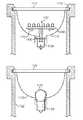
- FIG. 1is a cross-sectional view of the invention, including a reflector.
- FIG. 2is a perspective view, without showing a reflector.
- FIG. 3is a schematic diagram of an exemplary circuit implementing the driving circuit of this invention.
- FIG. 4is similar to FIG. 1 , except that it employs multiple LEDs and a converging lens.
- FIG. 5is a flow diagram of a flashlight related method.
- FIG. 6is another flow diagram of a flashlight related method.
- FIG. 7is a drawing showing a typical embodiment of a universal LED illumination device to retrofit an incandescent lightbulb application.
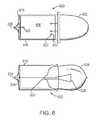
- FIG. 8is a drawing showing a typical embodiment of a universal LED illumination device in relation to an incandescent lightbulb.
- FIG. 9is a schematic representation of a DC circuit used for a typical embodiment of a universal LED illumination device.
- FIG. 10is a drawing showing a typical embodiment of a universal LED illumination device in relation to an incandescent flashlight bulb application.
- FIG. 11is a drawing showing a typical embodiment of a universal LED array illumination device in relation to an incandescent flashlight bulb application.
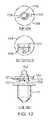
- FIG. 12is a drawing showing a typical embodiment of a universal LED illumination device to retrofit an incandescent lightbulb application.
- FIG. 13is a drawing showing a typical embodiment of a universal LED illumination device to retrofit an incandescent lightbulb application.
- FIG. 14is a drawing showing a typical embodiment of a universal LED illumination device to retrofit a halogen lightbulb application.
- FIG. 15is a drawing showing a typical embodiment of a universal LED illumination device to retrofit a focused beam incandescent flashlight application.
- FIG. 16is a schematic representation of a DC circuit used for a typical embodiment of a universal LED illumination device.
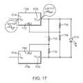
- FIG. 17is a schematic representation of an AC circuit used for a typical embodiment of a universal LED illumination device.
- FIG. 2A perspective view of a preferred physical form for this invention is shown in FIG. 2 .
- FIG. 1A cross-section of FIG. 2 appears as FIG. 1 .
- the standard light bulb power connectoris shown as pins 12 and 14 , respectively conductively connected to the positive and negative power source of the flashlight (presumably batteries).
- the light emitter 3typically would be an LED chip embedded in a transparent plastic lens 2 and a driving circuit embedded in a module. (Of course, potentially more than one light emitting chip could be used, perhaps to simulate white light with multiple chips each emitting a different wavelength.)
- the transparent lens 2 of the light emitterpreferably is so shaped that it refracts a majority of the emitted light laterally toward the reflector 21 .
- Reflector 21would ideally have the shape of a portion of a paraboloid, with the light-emitting chip 3 on the centerline (axis of revolution) near the focal point of the paraboloid.
- reflector 21could simply be a portion of a cone.
- the reflector of the Mini Maglite® and its housingmay be rotated with respect to the flashlight barrel and is attached thereto by the helically threaded, mating portions of the barrel and housing. As the reflector is rotated its focal point is moved along the centerline relative to the light-emitting chip 3 . As the focal point is moved relative to the chip 3 , the shape of the beam reflected off the reflector 21 is changed from a broad cone-like beam to a narrower beam.
- Light ray 23is exemplary of all such rays composing the beam.
- the driver circuit module of the present inventioncomprises a small conventional printed circuit board 4 , circuit components (such as commercially available integrated circuits represented by elements 15 and 17 in FIG. 1 ), a potting layer 6 protecting those circuit components, a socket 9 for the support and conductor leads of the light emitter (LED), and pins 12 and 14 equivalent to the connector of the original incandescent bulb.
- the pins 12 and 14might be instead some other type of connector, such as a standard screw or bayonet light bulb base.
- the dimensions of the module for the Mini Maglite®, for example,would be about 15 mm in diameter and about 3 mm thick—larger than the original incandescent bulb.
- the module 6provides a low friction surface in order for the reflector 21 to readily turn as it contacts module to preserve the focusing capability or to preserve the on-off switch capability.
- the protective material of the module 6must facilitate radiation and conduction of heat away from the light emitters and from the supporting circuit elements in module 6 .
- the materialfor instance, may be a thermally conductive epoxy.
- the moduleis geometrically shaped to maximize surface area within the limited volume to facilitate the radiation of heat from the emitters and the module.
- the surface of the modulemay be textured to increase its surface area.
- the reflectoritself could be fashioned from a thermally conductive material such as stamped aluminum. This would be particularly effective, because it directly contacts the module 6 in the preferred embodiment and because it has a relatively large surface area.
- a replacement reflectoris an optional, additional element of the invention.
- the replacement reflector 21would be essentially identical to the original reflector, except that a small rear portion is removed to account for the thickness of the driver circuit printed circuit board 4 and protective potting 6 .
- the shape of the replacementwould be equivalent to the original, except for the small portion removed from the smaller open end.
- the replacement reflector 21would be modified slightly in shape to account for the new position of the chip relative to the original position of the filament. That is, the relationship of the focal point of the new reflector to the chip would be about the same as the relationship of the focal point of the old reflector to the filament.
- FIG. 4An alternative embodiment is shown in FIG. 4 .
- the LEDsare off the midline axis, so the light will be spread out farther than with the case of FIG. 1 .
- One partial remedywould be to replace the usual flat protective window of the flashlight with a (converging) lens.
- One advantage of multiple LEDsis that they could generate an approximation to white light by mixing the colors of several LEDs (such as that of red, green, and blue LEDs).
- Using a diffusing lens 22 (or reflector 21 )which has a stippled or pebbled surface would smooth the appearance of the light, especially when multiple LEDs are present.
- FIG. 3shows a DC circuit used for a typical embodiment.
- a high frequency, low power DC-to-DC converter circuitis utilized to drive the LED 302 .
- the high frequency of operationallows components of small size to be used.
- a positive voltage sourceis introduced at +Vin 312 and branched to a capacitor C 1 316 and inductor L 1 320 and to two inputs (Vin 324 and EN 326 ) of a switching circuit 304 .
- the solid-state switching circuit 304regulates the input voltage Vin 324 to a specified value to achieve a switched output at SW 328 by receiving an enable signal EN 326 branched from Vin 324 .
- the inductor L 1 320is charged during the ON cycle phase of SW 328 and discharges in the OFF cycle phase to achieve the desired switched voltage output driving a Schottky diode D 1 306 that in turn drives the anode side 308 of the output LED 302 and capacitor C 3 318 which is terminated to ground.
- This Schottky diode D 1 306allows the current to flow in only one direction to the anode side 308 of the LED 302 via SW 328 .
- the Schottky diode D 1 306also assures that there is a quantity of rectification of the AC signal flowing through the circuit so that the LED only sees half of the AC cycle, effectively acting as a DC signal.
- Capacitor C 3 318becomes a charge reservoir, averaging out what would otherwise be a sinusoidally varying voltage with one half of the sine wave missing.
- the cathode side 310 of the LED 302is passed through ground via R- 4 322 and branched to the feedback FB pin 332 of the switching circuit 304 through resistor R 3 320 .
- the FB pin 332acts as half of an operational amplifier that is comparing the voltage at R- 4 322 above ground, to a reference voltage, (i.e., 1.23V).
- a reference voltagei.e. 123V.
- the FB pin 332therefore serves as feedback reference within the switching circuit 304 , determining the current values by comparing a feedback voltage to its internal reference and deciding whether more or less charge is needed, thereby regulating the circuit current.
- ⁇ Vin 314 , capacitors C 1 316 and C 3 318 , resistor R 4 322 and the ground terminal 330 of the switching circuit 304are all terminated to ground.
- a current sense resistoris used to provide the voltage feedback.
- An integrated circuit of small size, Texas Instruments TPS61040 or TPS61041is suitable for this purpose. Although designed for DC-to-DC operation in a suitable voltage range, the circuit can be easily modified to work at higher voltages by using a zener diode resistor combination, or to operate as an AC-to-DC converter by adding a rectifier circuit. Additional operational features such as light sensors, timers, etc., could be added to provide for dimming or automatic shut-off functions. Multiple colored LEDs can be used to vary the desired colored output. Although only one LED is shown, several LEDs can be combined in a series circuit, parallel circuit or series-parallel circuit up to the limitations of the IC used.
- An appropriate LEDmay be chosen for use in this circuit to suit the particular application and sized to closely match the bulb dimensions and intensities of conventional lamps.
- the circuit shown in FIG. 3can be implemented in either a constant voltage output design or a constant current output design.
- the constant current designhas advantages since light output is directly proportional to current, whereas slight variations in the LED manufacture require different operating voltages for a specific light output.
- an incandescent light source in an incandescent flashlightcan be replaced with at least one solid state light source and a cooperating printed circuit board such that the at least one solid state light source is located within an area circumscribed by a light reflecting surface and the cooperating printed circuit board is located within an overall envelope of the flashlight, (step 402 ).
- a light reflector arrangement of the incandescent flashlightcan be replaced with a smaller light reflector arrangement within a light reflector housing, and the steps of replacing the incandescent light source and reflector arrangement are carried out without changing the dimensions of the overall envelope of the flashlight, (step 404 ).
- an incandescent light sourcecan be replaced in an incandescent flashlight with at least one solid state light source and a cooperating printed circuit board such that the at least one solid state light source is located within an area circumscribed by a light reflecting surface and the cooperating printed circuit board is located within an overall envelope of the flashlight, (step 502 ).
- a given battery compartment volume of the flashlightcan be reduced such that the dimensions of an overall envelope of the flashlight remains unchanged, (step 504 ).
- FIG. 7is a drawing showing a typical embodiment of a universal LED illumination device to retrofit an incandescent lightbulb application.
- an LED illumination device 700may be made up of an LED lamp 702 that is connected to a printed circuit board 704 by an anode 726 wire at an LED anode connect 708 and a cathode 728 wire and an LED cathode connect 710 located on the printed circuit board 704 .
- This printed circuit board 704contains electronic circuitry placed in circuit area 706 and is of small size enabling the printed circuit board 704 to fit within the envelope of a standard bulb base 716 .
- the disclosed LED embodimentsare able to emit light in a narrow wavelength range resulting in the bulk of the energy consumed by the device to be emitted as visible light, thereby delivering much higher electrical to optical conversion efficiency than incandescent technology.
- red, green, and blue LEDscan be combined to produce white light
- UV emitting LEDscan be used with fluorescing materials to produce white light for general illuminating applications.
- Such LEDshave very long life compared to incandescent lights (50,000 hours vs. 3-30 hrs for incandescent flashlight bulbs) in addition to the high efficiency of LEDs.
- FIG. 8is a drawing showing a typical embodiment of a universal LED illumination device in relation to an incandescent lightbulb.
- an LED illumination device 800is contrasted with an incandescent lightbulb 850 .
- a comparable size and functional relationis demonstrated in the disclosed embodiment of an LED lamp 802 driven by a logic circuit 806 in connection with a standard bulb base 816 , mimicking the envelope of an incandescent bulb 826 with a resistive lighting filament 828 in a standard bulb base 816 .
- Both designsinclude a base 816 with +V in contact, 820 and 830 , and ⁇ V in contacts 822 and 832 isolated from one another by insulators 818 and 834 .
- FIG. 8further demonstrates the ability of an LED illumination device 800 to retrofit conventional incandescent bulbs in a variety of applications.
- FIG. 9is a schematic representation of a DC circuit used for a typical embodiment of a universal LED illumination device.
- a high frequency, low power DC-to-DC converter circuitis utilized to drive the LED 902 in the disclosed embodiment illustrated in FIG. 9 .
- the high frequency of operationallows components of small size to be used.
- a positive voltage sourceis introduced at +V in 912 and branched to a capacitor 916 and inductor 920 and to two inputs (V in 924 and EN 926 ) of a switching circuit 904 .
- the solid-state switching circuit 904regulates the input voltage V in 924 to a specified value to achieve a switched output at SW 928 by receiving an enable signal 926 branched from V in 924 .
- the inductor 920is charged during the ON cycle phase of SW 928 and discharges in the OFF cycle phase to achieve the desired switched voltage output driving a Schottky diode 906 that in turn drives the anode side 908 of the output LED 902 and capacitor 918 which is terminated to ground.
- This Schottky diode 906allows the current to flow in only one direction to the anode side 908 of the LED 902 via SW 928 .
- the Schottky diode 906also assures that there is a quantity of rectification of the AC signal flowing through the circuit so that the LED only sees half of the AC cycle, effectively acting as a DC signal.
- Capacitor 918becomes a charge reservoir, averaging out what would otherwise be a sinusoidally varying voltage with one half of the sine wave missing.
- the cathode side 910 of the LED 902is pass through ground via resistor 922 and branched to the feedback FB pin 932 of the switching circuit 904 through resistor 921 .
- the FB pin 932acts as half of an operational amplifier that is comparing the voltage at resistor 922 above ground, to a reference voltage, (i.e., 1.23V).
- a reference voltagei.e. 1.23V.
- the FB pin 932therefore serves as feedback reference within the switching circuit 904 , determining the current values by comparing a feedback voltage to its internal reference and deciding whether more or less charge is needed, thereby regulating the circuit current.
- ⁇ V in 914 , capacitors 916 and 918 , resistor 922 and the ground terminal 930 of the switching circuit 904are all terminated to ground.
- a current sense resistoris used to provide the voltage feedback.
- An integrated circuit of small size, Texas Instruments TPS61040 or TPS61041is suitable for this purpose. Although designed for DC-to-DC operation in a suitable voltage range, the circuit can be easily modified to work at higher voltages by using a zener diode resistor combination, or to operate as an AC-to-DC converter by adding a rectifier circuit. Additional operational features such as light sensors, pulse circuits etc., can be added to provide for flashing operation or dimming. Multiple colored LEDs can be used to vary the desired colored output. Although only one LED is shown, several LEDs can be combined in a series circuit, parallel circuit or series-parallel circuit up to the limitations of the IC used.
- An appropriate LEDmay be chosen for use in this circuit to suit the particular application and sized to closely match the bulb dimensions and intensities of conventional lamps.
- a productcan be obtained that has nearly identical or even superior form, fit, and function to traditional incandescent lamps.
- the circuit shown in FIG. 9can be implemented in either a constant voltage output design or a constant current output design.
- the constant current designhas advantages since light output is directly proportional to current, whereas slight variations in the LED manufacture require different operating voltages for a specific light output.
- the circuit shown in FIG. 9can be extremely compact, it can be incorporated in nearly any standard bulb base.
- the operating input voltage of the circuitis very wide (at least 1.5 V to 7 Volts), effectively drawing nearly all of the energy present in the battery pack, thereby making excellent utilization of available power.
- the disclosed circuitwill allow the LED light bulb to maintain constant light output under a wide range of voltage input. For example, a 6 V battery pack will still operate the LED, at full brightness, when it only delivers slightly in excess of 1.5 V. In other words, when the batteries are effectively “dead” with respect to conventional light bulbs, this embodiment will continue to operate as though the batteries were at full capacity.
- the circuit detailed in FIG. 9can be readily expanded or combined with additional circuitry to introduce a variety of additional functions to the device. These functions may include but are not limited to: a dimming feature that allows the bulb to be used at one or more brightness levels; brightness levels being used as a power saving mode or as an indication of low battery or deficient external power; an automatic shut-off timer function; light output color changes; variable light beam direction; backup power supply; combination of incandescent and LED lighting; voice activation; or the like.
- FIG. 10is a drawing showing a typical embodiment of a universal LED illumination device in relation to an incandescent flashlight bulb application.
- a flashlight body 1022 containing a standard incandescent bulb 1030 with a standard bulb base 1028is fixed within a reflector 1020 to reflect and project a beam of light through reflector cover 1024 .
- This same configurationcan be utilized with an LED lamp 1002 as the light source.
- a flashlight body 1012contains an LED lamp 1002 with a standard bulb base 1028 .
- a circuit board 1004 containing the necessary driver circuit and electronics for the LED lamp 1002is housed within this standard bulb base 1028 thereby providing an overall envelope which is nearly identical to it in the incandescent bulb.
- the LED lamp 1002is similarly fixed within a reflector 1010 to reflect and project a beam of light through reflector cover 1014 .
- This embodimentenables a single circuit and lighting device to be used with a variety of bulb bases thereby affording is an economic advantage both in manufacturing as well as to the user who may transfer the product to more than one application or stock one kind of bulb for multiple applications.
- This circuitis designed to adapt to various AC or DC power sources and accommodate the different voltages that may be present.
- FIG. 11is a drawing showing a typical embodiment of a universal LED array illumination device in relation to an incandescent flashlight bulb application.
- a flashlight body 1122 containing a standard incandescent bulb 1130 with a standard bulb base 1128is fixed within a reflector 1120 to reflect and project a beam of light through reflector cover 1124 .
- This same configurationcan be utilized with an LED array 1102 of lamps as the light source.
- a flashlight body 1112contains an LED array 1102 of lamps while still utilizing a standard bulb base 1128 .
- the LED array 1102can be mounted on a flat surface, such as a printed circuit (PC) board 1108 .
- PCprinted circuit
- a PC boardis equipped on its top surface with one or more LEDs connected in either a series or parallel circuit.
- This top surfacemay (or may not) contain electronic components such as ICs, resistors, capacitors and the like.
- the bottom surfacemay also contain circuitry and its associated electronic components such as a DC-to-DC converter circuit 1104 and may contain an electrical connector 1106 which mates to a complimentary connector mounted within a standard bulb base 1128 .
- the bulb base 1128 in this exampleis used to make electrical connections to an electrical source (not shown) and deliver the power to the wafer-shaped PC board 1108 .
- This DC-to-DC converter circuit 1104is designed to adapt to various power sources and accommodate the different voltages that may be present.
- Similar circuitsmay be utilized to allow the aforementioned embodiments to be powered by either AC or DC source current.
- the LED array 1102is similarly fixed within a reflector 1110 to reflect and project a beam of light through reflector cover 1114 .
- This embodimentenables a single circuit and lighting device to be used with a variety of bulb bases thereby affording is an economic advantage both in manufacturing as well as to the user who may transfer the product to more than one application.
- This single circuitis designed to adapt to various AC or DC power sources and accommodate the different voltages that may be present.
- FIG. 12is a drawing showing a typical embodiment of a universal LED illumination device to retrofit an incandescent lightbulb application.
- an LED 1202is mounted to a wafer PC board 1204 such that the LED 1202 will project light outward and approximately perpendicular to the top surface of the PC board 1204 .
- the LED 1202is mounted to the PC board 1204 by an anode 1226 and cathode 1228 attachments on the top surface.
- the converter and logic circuit 1206can be mounted on either or both sides of the wafer PC board 1204 and are shown in FIG. 12 on the bottom surface.
- This LED 1202 and associated converter and logic circuit 1206are connected to a 3-pin connector 1212 that facilitates an easy connection to a standard bulb base 1216 .
- This connectionis made through a single anode 1226 connector located in the center of the 3-pin connector 1212 , and two cathode 1228 connectors that have been bifurcated from the LED 1202 and placed lateral to the anode 1226 .
- This cathode geometryallows the LED and circuitry module to be placed into connection in either left or right orientation within the 3-pin connector 1212 .
- FIG. 13is a drawing showing a typical embodiment of a universal LED illumination device to retrofit an incandescent lightbulb application.
- a set of LEDs 1302(each on an LED holder 1330 ) is mounted in a triangular pattern to a wafer PC board 1304 in either a series or parallel configuration such that the LEDs 1302 will project light outward and approximately perpendicular to the top surface of the PC board 1304 .
- the LEDs 1302are mounted to the PC board 1304 by an anode 1326 and cathode 1328 attachments for each LED 1302 on the top surface.
- the converter and logic circuit 1306can be mounted on either or both sides of the wafer PC board 1304 and are shown in FIG. 13 on the bottom surface.
- LEDs 1302 and associated converter and logic circuit 1306are connected to a 3-pin connector 1312 that facilitates an easy connection to a standard bulb base 1316 .
- This connectionis made from each LED through to a single anode 1326 connector located in the center of the 3-pin connector 1312 , and two cathode 1328 connectors that have been bifurcated from each LED 1302 and placed lateral to the anode 1326 .
- This cathode geometryallows the LED and circuitry module to be placed into connection in either left or right orientation within the 3-pin connector 1312 .
- FIG. 14is a drawing showing a typical embodiment of a universal LED illumination device to retrofit a halogen lightbulb application.
- a group of LEDs 1402is mounted to a PC board 1404 such that the LEDs 1402 will project light outward and perpendicular to the top surface of the PC board 1404 to produce an LED halogen replacement bulb 1400 .
- the converter and logic circuit 1408can be mounted on either or both sides of the wafer PC board 1404 and are shown in FIG. 14 on the top surface.
- This top surfacecan be coated with a reflective surface 1412 to increase light output intensity by reflecting light otherwise lost and enhance heat dissipation of the LEDs and circuitry.
- LEDs 1402 and associated converter and logic circuit 1408are made to connect employing “bump ends” 1406 that adapt the PC board to fit and electrically connect within halogen bulb fixtures.
- the large area of PC board 1404 spaceadditionally allows for additional circuitry 1410 to be readily added to either side of the described embodiment.
- FIG. 15is a drawing showing a typical embodiment of a universal LED illumination device to retrofit a focused beam incandescent flashlight application.
- a reflective parabolic reflectoris an integral part of the product's feature set.
- the reflective reflectorcan be moved up and down by rotating a portion of the flashlight's barrel. When this is done, the reflector moves up and down thereby moving the bulb above, through and below the prime focus of the parabolic reflector. This has the effect of focusing or dispersing the light beam to give either a narrow spot or broad beam.
- LEDsusually contain focusing optics, a forward mounting as described above is usually an adequate implementation. However, to take advantage of unique features that may already be present in existing applications, an aftermarket implementation that addresses these specific features and associated needs is necessary.
- a flashlight body 1522 containing a standard incandescent bulb 1530 with a standard bulb base 1528is fixed within a reflective parabolic reflector 1520 to reflect and project a beam of light through reflector cover 1524 .
- the reflector 1520acts to reflect the light emanating from the filament in a standard incandescent bulb 1530 to a focused light beam 1540 .
- an LED replacement bulbis designed to allow light to emanate from one or more LEDs 1502 mounted to a PC board 1508 in flashlight body 1512 .
- the planar axis of the PC board 1508is mounted within a standard bulb base 1528 and positioned parallel to a focused beam of light 1550 . As illustrated in FIG.
- LEDs 1502are used, one each on either side of a metal core PC board 1508 .
- the LEDs 1502 in this embodimentsend their light directly towards the surface of the parabolic reflector 1510 and project as a focused light beam 1550 through reflector cover 1514 .
- the LEDs 1502are positioned such that they are in the same position relative to the focal point on the parabolic reflector 1510 as the filament 1538 is in the incandescent bulb 1530 it replaces. In this way, the focusing/defocusing feature works as it was intended to since the light is emitted either above or below the prime focus. Hence, both the user and the manufacturer can employ this product and gain the advantages of high efficiency and long life of the LEDs without losing the optical features of the product.
- Either surface of the PC board 1508may also contain circuitry and associated electronic components such as a DC-to-DC converter circuit 1504 and may contain an electrical connector that mates to a complimentary connector (not shown) mounted within a standard bulb base 1528 .
- the bulb base 1528 in this exampleis used to make electrical connections to an electrical power source (not shown) and deliver the power to the PC board 1508 .
- a metal core PC board 908 Ais shown in this embodiment to demonstrate the ease in which heat dissipation techniques can be adapted to the aforementioned embodiments.
- FIG. 16is a schematic representation of a DC circuit used for a typical embodiment of a universal LED illumination device.
- the circuit of FIG. 9is well suited for constant current operation of low power LEDs where the current required is on the order of 20 mA, the sense resistor 922 in that circuit dissipates power that may be less than optimal at higher current levels.
- An alternative higher current, high frequency, DC-to-DC converter circuit that generates a constant power output, ideal for higher current applications,is utilized to drive the LED 1602 in the disclosed embodiment illustrated in FIG. 16 .
- a positive voltage sourceis introduced at +V in 1612 and branched to an inductor 1620 and to inputs V CC 1624 of an IC driver circuit 1604 (i.e., Zetex ZXSC310).
- the solid-state driver circuit 1604regulates the input voltage V CC 1624 to a specified value to achieve a switched output at V Drive 1628 , which in turn drives an external transistor 1634 .
- the inductor 1620is charged during the ON cycle phase of transistor 1634 and discharges in the OFF cycle phase to achieve the desired switched voltage output driving a Schottky diode 1606 that in turn drives the anode side 1608 of the output LED 1602 and capacitor 1618 which is terminated to ground.
- This Schottky diode 1606allows the current to flow in only one direction to the anode side 1608 of the LED 1602 via transistor 1634 .
- the Schottky diode 1606also assures that there is a quantity of rectification of the AC signal flowing through the circuit so that the LED only sees half of the AC cycle, effectively acting as a DC signal.
- Capacitor 1618becomes a charge reservoir, averaging out what would otherwise be a sinusoidally varying voltage with one half of the sine wave missing.
- a low value sensing resistor 1620is connected to the ON phase of external transistor 1634 and minimizes power dissipation. The transistor switches ON and allows current to flow through resistor 1620 , where the voltage drop provides the necessary current sense input to the current sense pin 1632 of the IC 1604 .
- the cathode side 1610 of the LED 1602is pass through ground.
- the comparator 1604stops supplying current.
- the current sense pin 1632therefore serves as feedback reference within the driver circuit 1604 , determining the current values by comparing a feedback current to its internal reference and deciding whether more or less charge is needed, thereby regulating the circuit current.
- ⁇ V in 1614 , capacitors 1618 , and resistor 1620 and the ground terminal 1630 of the driver circuit 1604are all terminated to ground.
- FIG. 17is a schematic representation of an AC circuit used for a typical embodiment of a universal LED illumination device.
- FIG. 17illustrates a typical AC circuit suitable for driving a universal LED illumination device.
- a methodcan be used to rectify the AC voltage to produce a DC signal as referred to above.
- circuits that merely rectify the AC voltageare best suited for use with batteries and when the DC voltage available is less than or equal to the operating voltage of the array of one or more LEDs.
- a 14V AC sourceis often used as the power source and is excessive for one or two LEDs.
- an AC voltage regulatormay be used in conjunction with the LED that utilizes the inherent property of rectification of an LED that will generally withstand 5 V in reverse bias.
- An alternating current voltage sourceis introduced to two IC regulator circuits 1704 and 1706 (i.e., National LM317) at V in 1724 and V in 1734 .
- the solid-state regulator circuits 1704 and 1706regulate the positive and negative going potential using the internal voltage reference of the IC and chop the sinusoidal input from, for example 14V peak-to-peak (P-P) to 3.6 V P-P to set the voltage output at V out 1728 and V out 1738 .
- Chopped outputs V out 1728 and V out 1738feed through parallel ladder path, the first rung containing resistor 1720 and resistor 1730 in series, the second rung containing resistor 1740 and resistor 1750 in series, and the third rung containing an LED 1702 .
- the first rungis connected between resistor 1720 and resistor 1730 to a comparator input ADJ 1732 on regulator circuit 1704 and the second rung is connected between resistor 1740 and resistor 1750 to a comparator input ADJ 1742 on regulator circuit 1706 .
- These comparator inputs ADJ 1732 and ADJ 1742are used as a feedback loop to compare the external voltage reference to an internal voltage reference V ref to set the voltage output V out 1728 A and V out 1738 .
- the ratio of resistor 1740 /resistor 1750 (R 3 /R 4 ) and resistor 1720 /resistor 1730 (R 1 /R 2 )determine the positive and negative voltage maximum.
- the 14 V AC peak-to-peak signalis reduced to nearly a square wave with a 3.6V P-P max being used drive the LED 1702 , using the LED 1702 to rectify the signal.
- V out ⁇would be kept within a range well tolerated by the reverse characteristics of the LED 1702 .
Landscapes
- Engineering & Computer Science (AREA)
- General Engineering & Computer Science (AREA)
- Microelectronics & Electronic Packaging (AREA)
- Physics & Mathematics (AREA)
- Optics & Photonics (AREA)
- Circuit Arrangement For Electric Light Sources In General (AREA)
- Arrangement Of Elements, Cooling, Sealing, Or The Like Of Lighting Devices (AREA)
Abstract
Description
- 2 a transparent lens adapted to emit a majority of the light peripherally
- 3 at least one light-emitting semiconductor chip
- 4 a small (round) printed circuit board
- 6 hard protective material encasing the
electronic components - 9 a socket for the LED module comprising2 and3
- 12 the pin to be electrically connected to the positive side of the battery pack
- 14 the pin to be electrically connected to the negative side of the battery pack
- 15 an exemplary integrated circuit (IC) component
- 17 another integrated circuit (IC) component
- 21 replacement reflector (shorter than original), if necessary
- 22 lens replacing normal protective transparent window
- 23 exemplary focused light ray
- 302, . . . ,333 components of the driving circuit
Claims (35)
Priority Applications (1)
| Application Number | Priority Date | Filing Date | Title |
|---|---|---|---|
| US13/961,454US9103511B2 (en) | 2003-09-12 | 2013-08-07 | Universal light emitting diode illumination device and method |
Applications Claiming Priority (9)
| Application Number | Priority Date | Filing Date | Title |
|---|---|---|---|
| US50249503P | 2003-09-12 | 2003-09-12 | |
| US10/820,930US7318661B2 (en) | 2003-09-12 | 2004-04-08 | Universal light emitting illumination device and method |
| US11/026,796US7300173B2 (en) | 2004-04-08 | 2004-12-31 | Replacement illumination device for a miniature flashlight bulb |
| US11/831,791US7448770B2 (en) | 2004-04-08 | 2007-07-31 | Replacement illumination device for a miniature flashlight bulb |
| US12/244,645US7699494B2 (en) | 2004-04-08 | 2008-10-02 | Replacement illumination device for a miniature flashlight bulb |
| US12/716,633US8033682B2 (en) | 2004-04-08 | 2010-03-03 | Replacement illumination device for an incandescent lamp |
| US13/225,695US8240873B2 (en) | 2003-09-12 | 2011-09-06 | Universal light emitting diode illumination device and method |
| US13/545,449US8529088B2 (en) | 2003-09-12 | 2012-07-10 | Universal light emitting diode illumination device and method |
| US13/961,454US9103511B2 (en) | 2003-09-12 | 2013-08-07 | Universal light emitting diode illumination device and method |
Related Parent Applications (1)
| Application Number | Title | Priority Date | Filing Date |
|---|---|---|---|
| US13/545,449ContinuationUS8529088B2 (en) | 2003-09-12 | 2012-07-10 | Universal light emitting diode illumination device and method |
Publications (2)
| Publication Number | Publication Date |
|---|---|
| US20140036488A1 US20140036488A1 (en) | 2014-02-06 |
| US9103511B2true US9103511B2 (en) | 2015-08-11 |
Family
ID=38971262
Family Applications (11)
| Application Number | Title | Priority Date | Filing Date |
|---|---|---|---|
| US11/026,796Expired - Fee RelatedUS7300173B2 (en) | 2003-09-12 | 2004-12-31 | Replacement illumination device for a miniature flashlight bulb |
| US11/831,791Expired - Fee RelatedUS7448770B2 (en) | 2003-09-12 | 2007-07-31 | Replacement illumination device for a miniature flashlight bulb |
| US12/244,645Expired - LifetimeUS7699494B2 (en) | 2003-09-12 | 2008-10-02 | Replacement illumination device for a miniature flashlight bulb |
| US12/716,633Expired - LifetimeUS8033682B2 (en) | 2003-09-12 | 2010-03-03 | Replacement illumination device for an incandescent lamp |
| US13/225,695Expired - Fee RelatedUS8240873B2 (en) | 2003-09-12 | 2011-09-06 | Universal light emitting diode illumination device and method |
| US13/225,691Expired - Fee RelatedUS8328386B2 (en) | 2003-09-12 | 2011-09-06 | Universal light emitting diode illumination device and method |
| US13/225,688Expired - LifetimeUS8328385B2 (en) | 2003-09-12 | 2011-09-06 | Universal light emitting diode illumination device and method |
| US13/545,449Expired - Fee RelatedUS8529088B2 (en) | 2003-09-12 | 2012-07-10 | Universal light emitting diode illumination device and method |
| US13/961,498Expired - LifetimeUS9057489B2 (en) | 2003-09-12 | 2013-08-07 | Universal light emitting diode illumination device and method |
| US13/961,454Expired - LifetimeUS9103511B2 (en) | 2003-09-12 | 2013-08-07 | Universal light emitting diode illumination device and method |
| US14/711,328AbandonedUS20150241044A1 (en) | 2003-09-12 | 2015-05-13 | Universal light emitting diode illumiation device and method |
Family Applications Before (9)
| Application Number | Title | Priority Date | Filing Date |
|---|---|---|---|
| US11/026,796Expired - Fee RelatedUS7300173B2 (en) | 2003-09-12 | 2004-12-31 | Replacement illumination device for a miniature flashlight bulb |
| US11/831,791Expired - Fee RelatedUS7448770B2 (en) | 2003-09-12 | 2007-07-31 | Replacement illumination device for a miniature flashlight bulb |
| US12/244,645Expired - LifetimeUS7699494B2 (en) | 2003-09-12 | 2008-10-02 | Replacement illumination device for a miniature flashlight bulb |
| US12/716,633Expired - LifetimeUS8033682B2 (en) | 2003-09-12 | 2010-03-03 | Replacement illumination device for an incandescent lamp |
| US13/225,695Expired - Fee RelatedUS8240873B2 (en) | 2003-09-12 | 2011-09-06 | Universal light emitting diode illumination device and method |
| US13/225,691Expired - Fee RelatedUS8328386B2 (en) | 2003-09-12 | 2011-09-06 | Universal light emitting diode illumination device and method |
| US13/225,688Expired - LifetimeUS8328385B2 (en) | 2003-09-12 | 2011-09-06 | Universal light emitting diode illumination device and method |
| US13/545,449Expired - Fee RelatedUS8529088B2 (en) | 2003-09-12 | 2012-07-10 | Universal light emitting diode illumination device and method |
| US13/961,498Expired - LifetimeUS9057489B2 (en) | 2003-09-12 | 2013-08-07 | Universal light emitting diode illumination device and method |
Family Applications After (1)
| Application Number | Title | Priority Date | Filing Date |
|---|---|---|---|
| US14/711,328AbandonedUS20150241044A1 (en) | 2003-09-12 | 2015-05-13 | Universal light emitting diode illumiation device and method |
Country Status (1)
| Country | Link |
|---|---|
| US (11) | US7300173B2 (en) |
Cited By (2)
| Publication number | Priority date | Publication date | Assignee | Title |
|---|---|---|---|---|
| US20150272262A1 (en)* | 2014-03-31 | 2015-10-01 | Sam Escamilla | Illuminated Shoe Insert |
| US20150292686A1 (en)* | 2014-04-09 | 2015-10-15 | Cree, Inc. | Led lamp |
Families Citing this family (94)
| Publication number | Priority date | Publication date | Assignee | Title |
|---|---|---|---|---|
| US7300173B2 (en) | 2004-04-08 | 2007-11-27 | Technology Assessment Group, Inc. | Replacement illumination device for a miniature flashlight bulb |
| US7777430B2 (en) | 2003-09-12 | 2010-08-17 | Terralux, Inc. | Light emitting diode replacement lamp |
| US8746930B2 (en) | 2003-11-04 | 2014-06-10 | Terralux, Inc. | Methods of forming direct and decorative illumination |
| US8632215B2 (en) | 2003-11-04 | 2014-01-21 | Terralux, Inc. | Light emitting diode replacement lamp |
| US8702275B2 (en) | 2003-11-04 | 2014-04-22 | Terralux, Inc. | Light-emitting diode replacement lamp |
| US7758223B2 (en)* | 2005-04-08 | 2010-07-20 | Toshiba Lighting & Technology Corporation | Lamp having outer shell to radiate heat of light source |
| US7633177B2 (en)* | 2005-04-14 | 2009-12-15 | Natural Forces, Llc | Reduced friction wind turbine apparatus and method |
| US20070025109A1 (en)* | 2005-07-26 | 2007-02-01 | Yu Jing J | C7, C9 LED bulb and embedded PCB circuit board |
| US7563070B2 (en)* | 2005-10-27 | 2009-07-21 | Hong Fu Jin Precision Industry (Shen Zhen) Co., Ltd. | Cooling fan |
| ES2718085T3 (en)* | 2005-11-17 | 2019-06-27 | Signify Holding Bv | Lamp set |
| US7488097B2 (en)* | 2006-02-21 | 2009-02-10 | Cml Innovative Technologies, Inc. | LED lamp module |
| DE102006021055A1 (en)* | 2006-05-05 | 2007-11-08 | Patent-Treuhand-Gesellschaft für elektrische Glühlampen mbH | Adapter for a built-in lamp |
| WO2008049381A1 (en)* | 2006-10-25 | 2008-05-02 | Osram Gesellschaft mit beschränkter Haftung | Illumination device |
| WO2008136654A1 (en)* | 2007-05-07 | 2008-11-13 | Thean Kwai Kong | The replacement of all light bulb systems to advanced technology light emitting diode (led) lamps |
| JP4569683B2 (en) | 2007-10-16 | 2010-10-27 | 東芝ライテック株式会社 | Light emitting element lamp and lighting apparatus |
| US10655837B1 (en) | 2007-11-13 | 2020-05-19 | Silescent Lighting Corporation | Light fixture assembly having a heat conductive cover with sufficiently large surface area for improved heat dissipation |
| JP5353216B2 (en)* | 2008-01-07 | 2013-11-27 | 東芝ライテック株式会社 | LED bulb and lighting fixture |
| US8212483B2 (en)* | 2008-06-12 | 2012-07-03 | Infineon Technologies Austria Ag | Brightness controlled light source |
| CN103470983A (en)* | 2008-06-27 | 2013-12-25 | 东芝照明技术株式会社 | Light-emitting element lamp and lighting equipment |
| US8297796B2 (en)* | 2008-08-01 | 2012-10-30 | Terralux, Inc. | Adjustable beam portable light |
| US8858032B2 (en)* | 2008-10-24 | 2014-10-14 | Cree, Inc. | Lighting device, heat transfer structure and heat transfer element |
| US7922366B2 (en)* | 2008-11-07 | 2011-04-12 | Chia-Mao Li | LED light source with light refractor and reflector |
| JP5333758B2 (en) | 2009-02-27 | 2013-11-06 | 東芝ライテック株式会社 | Lighting device and lighting fixture |
| US8465177B2 (en)* | 2009-06-19 | 2013-06-18 | Chih-Ming Yu | Heat dissipation enhanced LED lamp |
| JP5348410B2 (en) | 2009-06-30 | 2013-11-20 | 東芝ライテック株式会社 | Lamp with lamp and lighting equipment |
| JP2011049527A (en) | 2009-07-29 | 2011-03-10 | Toshiba Lighting & Technology Corp | Led lighting equipment |
| JP2011065979A (en)* | 2009-08-18 | 2011-03-31 | Sharp Corp | Light source device |
| JP2011071242A (en) | 2009-09-24 | 2011-04-07 | Toshiba Lighting & Technology Corp | Light emitting device and illuminating device |
| JP2011091033A (en) | 2009-09-25 | 2011-05-06 | Toshiba Lighting & Technology Corp | Light-emitting module, bulb-shaped lamp and lighting equipment |
| CN102032481B (en) | 2009-09-25 | 2014-01-08 | 东芝照明技术株式会社 | Lighting lamps and lighting fixtures with sockets |
| US8678618B2 (en) | 2009-09-25 | 2014-03-25 | Toshiba Lighting & Technology Corporation | Self-ballasted lamp having a light-transmissive member in contact with light emitting elements and lighting equipment incorporating the same |
| US8324789B2 (en)* | 2009-09-25 | 2012-12-04 | Toshiba Lighting & Technology Corporation | Self-ballasted lamp and lighting equipment |
| ES2535385T3 (en)* | 2009-10-22 | 2015-05-11 | Thermal Solution Resources, Llc | Overmolded LED lighting assembly and manufacturing method |
| JP5174835B2 (en)* | 2010-01-08 | 2013-04-03 | シャープ株式会社 | LED bulb |
| JP5257622B2 (en) | 2010-02-26 | 2013-08-07 | 東芝ライテック株式会社 | Light bulb shaped lamp and lighting equipment |
| DE102010013484A1 (en)* | 2010-03-30 | 2011-10-06 | Hella Kgaa Hueck & Co. | Lighting device for vehicles |
| CN103189684B (en)* | 2010-10-29 | 2016-08-17 | 欧司朗股份有限公司 | Light fixture |
| CN102720983B (en)* | 2011-03-29 | 2015-03-25 | 海洋王照明科技股份有限公司 | Power-optional tunnel lamp |
| CN102734647B (en)* | 2011-04-01 | 2015-07-29 | 亿光电子(中国)有限公司 | White lumination system |
| JP6010116B2 (en)* | 2011-06-06 | 2016-10-19 | フィリップス ライティング ホールディング ビー ヴィ | Socket, lighting module, and lighting fixture |
| CN102261591A (en)* | 2011-08-10 | 2011-11-30 | 戴培钧 | Light emitting diode (LED) lamp capable of emitting light reversely |
| US8692473B2 (en)* | 2011-08-23 | 2014-04-08 | Mag Instrument, Inc. | Portable lighting device |
| CN102364210A (en)* | 2011-10-25 | 2012-02-29 | 江门海琪电子科技有限公司 | LED (Light-Emitting Diode) lamp with hidden heat radiator |
| CN102364214A (en)* | 2011-11-01 | 2012-02-29 | 西安金诺光电科技有限公司 | Light-emitting diode (LED) bulb |
| TWM426729U (en)* | 2011-11-15 | 2012-04-11 | Unity Opto Technology Co Ltd | Improved LED bulb structure |
| US8777443B2 (en)* | 2011-12-13 | 2014-07-15 | Kuo-Fu Yang | Split type LED lamp |
| US8870408B2 (en) | 2012-04-02 | 2014-10-28 | Streamlight, Inc. | Portable light and work light adapter therefor |
| JP2014011045A (en)* | 2012-06-29 | 2014-01-20 | Toshiba Lighting & Technology Corp | Lighting device and lighting system |
| CN102809128B (en)* | 2012-07-27 | 2014-03-05 | 重庆雷士实业有限公司 | Semiconductor lighting device |
| CN102818190A (en)* | 2012-08-08 | 2012-12-12 | 上海微分节能科技有限公司 | Crystal flower type light source, lamp bulb and pendant lamp |
| US9204504B2 (en) | 2012-09-17 | 2015-12-01 | Energy Focus, Inc. | LED lamp system |
| USD740987S1 (en) | 2012-10-01 | 2015-10-13 | Streamlight, Inc. | Portable light |
| US20140092590A1 (en)* | 2012-10-01 | 2014-04-03 | Rambus Delaware Llc | Led flashlight |
| US20140153241A1 (en)* | 2012-12-01 | 2014-06-05 | Lsi Industries, Inc. | Display board and display board components |
| US9062863B2 (en)* | 2012-12-10 | 2015-06-23 | Avago Technologies General Ip (Singapore) Pte. Ltd. | System, device, and method for adjusting color output through active cooling mechanism |
| US9313849B2 (en) | 2013-01-23 | 2016-04-12 | Silescent Lighting Corporation | Dimming control system for solid state illumination source |
| DE102013201219A1 (en)* | 2013-01-25 | 2014-07-31 | Osram Opto Semiconductors Gmbh | Lamp |
| TWM462333U (en)* | 2013-02-05 | 2013-09-21 | Hep Tech Co Ltd | Switchable dimming apparatus for LED |
| US8884530B2 (en)* | 2013-02-07 | 2014-11-11 | Wen-Sung Lee | Intelligent illuminating device |
| EP2775598B1 (en)* | 2013-03-05 | 2018-01-17 | Dialog Semiconductor GmbH | Active avalanche protection for flyback converter |
| USD715481S1 (en)* | 2013-03-11 | 2014-10-14 | Wan-Jiong Lin | Lens |
| USD715991S1 (en)* | 2013-03-11 | 2014-10-21 | Wan-Jiong Lin | Lens |
| USD715990S1 (en)* | 2013-03-11 | 2014-10-21 | Wan-Jiong Lin | Lens |
| US10265539B2 (en) | 2013-04-30 | 2019-04-23 | Lpi, Inc. | Therapeutic LED system for a hot tub |
| CN104344355A (en)* | 2013-08-08 | 2015-02-11 | 欧司朗股份有限公司 | Light-emitting device with zoom function |
| US9976710B2 (en) | 2013-10-30 | 2018-05-22 | Lilibrand Llc | Flexible strip lighting apparatus and methods |
| JP6467206B2 (en)* | 2014-01-28 | 2019-02-06 | 株式会社小糸製作所 | Light source unit |
| US9410688B1 (en) | 2014-05-09 | 2016-08-09 | Mark Sutherland | Heat dissipating assembly |
| US9488352B2 (en)* | 2014-05-28 | 2016-11-08 | Technical Consumer Products, Inc. | Radio frequency (RF) signal pathway for a lamp antenna |
| US9380653B1 (en) | 2014-10-31 | 2016-06-28 | Dale Stepps | Driver assembly for solid state lighting |
| EP3238278B1 (en)* | 2014-12-22 | 2020-03-04 | MAG Instrument, Inc. | Improved efficiency lighting apparatus with led directly mounted to a heatsink |
| FR3032516B1 (en)* | 2015-02-06 | 2021-04-16 | Valeo Vision | LUMINOUS MODULE REFLECTOR DEVICE WITH ELECTROMAGNETIC SHIELDING |
| DE202015102507U1 (en)* | 2015-05-15 | 2015-06-10 | Bernd Beisse | LED light |
| USD811627S1 (en) | 2016-06-16 | 2018-02-27 | Curtis Alan Roys | LED lamp |
| JP6508468B2 (en)* | 2015-07-24 | 2019-05-08 | 東芝ライテック株式会社 | Vehicle lighting device and vehicle lighting device |
| US11060702B2 (en) | 2016-03-08 | 2021-07-13 | Ecosense Lighting Inc. | Lighting system with lens assembly |
| MY170228A (en)* | 2016-03-31 | 2019-07-10 | Fuji Oil Holdings Inc | Fat composition for low-trans fat, non-tempered chocolate and chocolate |
| US10041657B2 (en)* | 2016-06-13 | 2018-08-07 | Rebo Lighting & Electronics, Llc | Clip unit and edge mounted light emitting diode (LED) assembly comprising a clip unit |
| WO2018140727A1 (en) | 2017-01-27 | 2018-08-02 | Lilibrand Llc | Lighting systems with high color rendering index and uniform planar illumination |
| US12388056B1 (en) | 2017-01-27 | 2025-08-12 | Korrus, Inc. | Linear lighting systems and processes |
| US10435175B2 (en) | 2017-01-31 | 2019-10-08 | Honeywell International Inc. | Light emitting diode lamp assembly |
| US20180328552A1 (en) | 2017-03-09 | 2018-11-15 | Lilibrand Llc | Fixtures and lighting accessories for lighting devices |
| USD901754S1 (en) | 2017-04-14 | 2020-11-10 | RetroLED Components, LLC | Lamp support |
| USD851816S1 (en) | 2017-04-14 | 2019-06-18 | Curtis A. Roys | Lamp support |
| US10690312B2 (en) | 2017-05-18 | 2020-06-23 | Tri Lite, Inc. | Light emitting diode signal light |
| US10856679B2 (en)* | 2017-07-28 | 2020-12-08 | Just Funky Llc | Illumination element receptacle |
| US11041609B2 (en) | 2018-05-01 | 2021-06-22 | Ecosense Lighting Inc. | Lighting systems and devices with central silicone module |
| US10443834B1 (en)* | 2018-06-06 | 2019-10-15 | Mag Instrument, Inc. | LED flashlight with improved heat sink |
| US10683988B2 (en)* | 2018-10-04 | 2020-06-16 | Elemental LED, Inc. | Mirrored LED lighting |
| US10605412B1 (en) | 2018-11-16 | 2020-03-31 | Emeryallen, Llc | Miniature integrated omnidirectional LED bulb |
| US11353200B2 (en) | 2018-12-17 | 2022-06-07 | Korrus, Inc. | Strip lighting system for direct input of high voltage driving power |
| CN109695842B (en)* | 2019-01-07 | 2024-06-11 | 佛山电器照明股份有限公司 | LED lamp |
| US11002438B2 (en) | 2019-04-03 | 2021-05-11 | Sidney Howard Norton | Adjustable clip-on base for LED assembly |
| CN113503475B (en)* | 2021-06-25 | 2023-02-24 | 浙江浩腾电子科技股份有限公司 | A multifunctional solar voice lighting system |
Citations (110)
| Publication number | Priority date | Publication date | Assignee | Title |
|---|---|---|---|---|
| US3795830A (en) | 1972-08-17 | 1974-03-05 | Shelton J | Led slidebase switchboard lamp |
| US4211955A (en) | 1978-03-02 | 1980-07-08 | Ray Stephen W | Solid state lamp |
| US4214295A (en) | 1975-12-22 | 1980-07-22 | Oldham Batteries Limited | Portable electric lamp adjustable from spot beam to diffused beam |
| US4727289A (en) | 1985-07-22 | 1988-02-23 | Stanley Electric Co., Ltd. | LED lamp |
| US4783726A (en) | 1987-06-12 | 1988-11-08 | Wang Chern J | Modular light device |
| US4999750A (en) | 1989-07-20 | 1991-03-12 | Gammache Richard J | Flashlight with rotatable head assembly |
| US5097180A (en) | 1990-09-14 | 1992-03-17 | Roger Ignon | Flickering candle lamp |
| US5189339A (en) | 1990-09-05 | 1993-02-23 | Applied Lumens, Ltd. | Fluorescent lamp assemblies |
| US5222800A (en) | 1992-01-28 | 1993-06-29 | The Genlyte Group Incorporated | Recessed lighting fixture |
| US5463280A (en) | 1994-03-03 | 1995-10-31 | National Service Industries, Inc. | Light emitting diode retrofit lamp |
| US5465197A (en) | 1994-06-07 | 1995-11-07 | Chien; Tseng-Lu | Portable light |
| US5473525A (en) | 1993-02-24 | 1995-12-05 | Stout; Gary F. | Discreet display lamp |
| US5506760A (en) | 1993-07-01 | 1996-04-09 | Temic Telefunken Microelectronic Gmbh | Light fitting unit for illuminated signs |
| US5555161A (en) | 1995-09-11 | 1996-09-10 | Delco Electronics Corporation | Bi-functional light pipe and display assembly |
| US5561346A (en) | 1994-08-10 | 1996-10-01 | Byrne; David J. | LED lamp construction |
| US5575459A (en) | 1995-04-27 | 1996-11-19 | Uniglo Canada Inc. | Light emitting diode lamp |
| US5632551A (en) | 1994-07-18 | 1997-05-27 | Grote Industries, Inc. | LED vehicle lamp assembly |
| US5655830A (en) | 1993-12-01 | 1997-08-12 | General Signal Corporation | Lighting device |
| US5663719A (en) | 1993-04-29 | 1997-09-02 | Electro-Tech's | LED traffic signal light with automatic low-line voltage compensating circuit |
| US5749646A (en) | 1992-01-17 | 1998-05-12 | Brittell; Gerald A. | Special effect lamps |
| US5806973A (en) | 1996-06-28 | 1998-09-15 | The L.D. Kichler Co. | Lamp with illuminated body |
| US5850126A (en) | 1997-04-11 | 1998-12-15 | Kanbar; Maurice S. | Screw-in led lamp |
| US5936599A (en) | 1995-01-27 | 1999-08-10 | Reymond; Welles | AC powered light emitting diode array circuits for use in traffic signal displays |
| US5994845A (en) | 1997-04-24 | 1999-11-30 | Ventur Research & Development Inc. | Electrical light socket |
| US6019493A (en) | 1998-03-13 | 2000-02-01 | Kuo; Jeffrey | High efficiency light for use in a traffic signal light, using LED's |
| US6091614A (en) | 1997-12-17 | 2000-07-18 | Ecolux Inc. | Voltage booster for enabling the power factor controller of a LED lamp upon low ac or dc supply |
| US6111739A (en) | 1999-08-11 | 2000-08-29 | Leotek Electronics Corporation | LED power supply with temperature compensation |
| US6140776A (en) | 1999-04-06 | 2000-10-31 | Rachwal; Erwin J. | Flashlight |
| US6150771A (en) | 1997-06-11 | 2000-11-21 | Precision Solar Controls Inc. | Circuit for interfacing between a conventional traffic signal conflict monitor and light emitting diodes replacing a conventional incandescent bulb in the signal |
| US6161910A (en) | 1999-12-14 | 2000-12-19 | Aerospace Lighting Corporation | LED reading light |
| US6184628B1 (en) | 1999-11-30 | 2001-02-06 | Douglas Ruthenberg | Multicolor led lamp bulb for underwater pool lights |
| US6190020B1 (en) | 1999-06-23 | 2001-02-20 | Fred Jack Hartley | Light producing assembly for a flashlight |
| US6218785B1 (en) | 1999-03-19 | 2001-04-17 | Incerti & Simonini Di Incerti Edda & C. S.N.C. | Low-tension lighting device |
| US6220722B1 (en) | 1998-09-17 | 2001-04-24 | U.S. Philips Corporation | Led lamp |
| US6232784B1 (en)* | 1997-09-22 | 2001-05-15 | Richard Dulasky | Circuit continuity tester and method |
| US6234645B1 (en) | 1998-09-28 | 2001-05-22 | U.S. Philips Cororation | LED lighting system for producing white light |
| US6234648B1 (en) | 1998-09-28 | 2001-05-22 | U.S. Philips Corporation | Lighting system |
| US6242870B1 (en) | 1997-10-16 | 2001-06-05 | Fujitsu Limited | Light emitting device driving circuit |
| US6285139B1 (en) | 1999-12-23 | 2001-09-04 | Gelcore, Llc | Non-linear light-emitting load current control |
| US6310445B1 (en) | 2000-01-03 | 2001-10-30 | Dialight Corporation | Led indicator disable circuit and led indicator incorporating the led indicator disable circuit |
| US6313589B1 (en) | 1999-11-16 | 2001-11-06 | Tokiwa Dengyo Co., Ltd. | Power supply circuit for traffic signal lights utilizing LEDs |
| US6357889B1 (en) | 1999-12-01 | 2002-03-19 | General Electric Company | Color tunable light source |
| US6371636B1 (en) | 1999-05-24 | 2002-04-16 | Jam Strait, Inc. | LED light module for vehicles |
| US6380865B1 (en) | 1999-04-06 | 2002-04-30 | 911 Emergency Products, Inc. | Replacement led lamp assembly and modulated power intensity for light source |
| US20020130786A1 (en) | 2001-01-16 | 2002-09-19 | Visteon Global Technologies,Inc. | Series led backlight control circuit |
| US20020141196A1 (en) | 2001-03-30 | 2002-10-03 | Richard Camarota | Lamp assembly with selectively positionable bulb |
| US6485160B1 (en) | 2001-06-25 | 2002-11-26 | Gelcore Llc | Led flashlight with lens |
| US20020176250A1 (en)* | 2001-05-26 | 2002-11-28 | Gelcore, Llc | High power led power pack for spot module illumination |
| US20030039122A1 (en) | 2001-08-24 | 2003-02-27 | Densen Cao | Light source using semiconductor devices mounted on a heat sink |
| US6528954B1 (en) | 1997-08-26 | 2003-03-04 | Color Kinetics Incorporated | Smart light bulb |
| US20030067787A1 (en) | 2001-10-04 | 2003-04-10 | Koito Manufacturing Co., Ltd. | Vehicle lamp |
| US20030076128A1 (en) | 1999-03-12 | 2003-04-24 | Mikio Ohtaki | Semiconductor device test method |
| US6570505B1 (en) | 1997-12-30 | 2003-05-27 | Gelcore Llc | LED lamp with a fault-indicating impedance-changing circuit |
| US20030103348A1 (en) | 2001-11-30 | 2003-06-05 | Sheng-Tien Hung | Projection lamp |
| US6580228B1 (en) | 2000-08-22 | 2003-06-17 | Light Sciences Corporation | Flexible substrate mounted solid-state light sources for use in line current lamp sockets |
| US20030112627A1 (en) | 2000-09-28 | 2003-06-19 | Deese Raymond E. | Flexible sign illumination apparatus, system and method |
| US6595671B2 (en) | 2000-05-10 | 2003-07-22 | Maxime Lefebvre | Rugged, waterproof LED array lighting system |
| US20030179548A1 (en) | 2002-03-21 | 2003-09-25 | General Electric Company | Flexible interconnect structures for electrical devices and light sources incorporating the same |
| US6626557B1 (en)* | 1999-12-29 | 2003-09-30 | Spx Corporation | Multi-colored industrial signal device |
| US6634771B2 (en) | 2001-08-24 | 2003-10-21 | Densen Cao | Semiconductor light source using a primary and secondary heat sink combination |
| US6644841B2 (en) | 2002-03-01 | 2003-11-11 | Gelcore Llc | Light emitting diode reflector |
| US20030210552A1 (en) | 2002-03-13 | 2003-11-13 | Reinhold Barlian | Indicating light |
| US20040028099A1 (en) | 2002-07-24 | 2004-02-12 | Fujitsu Limited | Drive circuit and drive method of semiconductor laser module provided with electro-absorption type optical modulator |
| US20040070990A1 (en) | 2002-10-01 | 2004-04-15 | Witold Szypszak | LED illuminator and method of manufacture |
| JP2004119287A (en) | 2002-09-27 | 2004-04-15 | Toto Ltd | Lighting equipment for toilet |
| US6727652B2 (en) | 2000-12-21 | 2004-04-27 | Gamesman Limited | Lamps |
| US6733152B2 (en) | 1991-06-21 | 2004-05-11 | Mag Instrument, Inc. | Flashlight |
| JP2004146205A (en) | 2002-10-24 | 2004-05-20 | Fuji Photo Film Co Ltd | Battery storing device |
| US6791283B2 (en) | 2001-09-07 | 2004-09-14 | Opalec | Dual mode regulated light-emitting diode module for flashlights |
| US6793374B2 (en) | 1998-09-17 | 2004-09-21 | Simon H. A. Begemann | LED lamp |
| US20040189262A1 (en) | 2003-03-10 | 2004-09-30 | Leddynamics | Circuit devices, circuit devices which include light emitting diodes, assemblies which include such circuit devices, flashlights which include such assemblies, and methods for directly replacing flashlight bulbs |
| US20040190286A1 (en) | 2003-03-25 | 2004-09-30 | Chapman Leonard T. | Flashlight |
| US6819056B2 (en) | 2003-04-15 | 2004-11-16 | Yeoujyi Electronics Co., Ltd. | Color-changing bulb of instrument panel of a vehicle |
| US6853151B2 (en) | 2002-11-19 | 2005-02-08 | Denovo Lighting, Llc | LED retrofit lamp |
| US6857756B2 (en) | 2001-04-11 | 2005-02-22 | General Manufacturing, Inc. | LED work light |
| US20050052865A1 (en) | 2003-09-05 | 2005-03-10 | Guide Corporation | Lamp housing containing an integrated LED support structure |
| US20050057187A1 (en) | 2003-09-12 | 2005-03-17 | Technology Assessment Group Inc. | Universal light emitting illumination device and method |
| US6871983B2 (en)* | 2001-10-25 | 2005-03-29 | Tir Systems Ltd. | Solid state continuous sealed clean room light fixture |
| US6880951B2 (en) | 2002-04-04 | 2005-04-19 | Altec Co., Ltd. | Flashlight using a light emitting diode as a lamp |
| US6893140B2 (en) | 2002-12-13 | 2005-05-17 | W. T. Storey, Inc. | Flashlight |
| US6924605B2 (en) | 2002-11-27 | 2005-08-02 | James K. Chun | Combination voltage detector and LED flashlight |
| US6924606B2 (en) | 2003-09-16 | 2005-08-02 | Beyond Innovation Technology Co., Ltd. | Low-visual noise, jitterized pulse width modulation brightness control circuit |
| US6948829B2 (en) | 2004-01-28 | 2005-09-27 | Dialight Corporation | Light emitting diode (LED) light bulbs |
| US20050225985A1 (en) | 2004-04-08 | 2005-10-13 | Technology Assessment Group Inc. | Replacement illumination device for a miniature flashlight bulb |
| US20050231948A1 (en) | 2001-09-07 | 2005-10-20 | Pohlert Rudy G | Lighting apparatus with adjustable lenses or filters |
| US6957897B1 (en) | 2000-06-27 | 2005-10-25 | General Electric Company | Flashlight with light emitting diode source |
| US6981784B2 (en) | 2002-05-30 | 2006-01-03 | Gelcore, Llc | Side projecting LED signal |
| US20060012997A1 (en) | 2004-07-16 | 2006-01-19 | Anthony Catalano | Light emitting diode replacement lamp |
| US7008084B2 (en) | 2003-01-03 | 2006-03-07 | Galli Robert D | Lighting head assembly with integrated heat sink |
| US7118249B2 (en) | 2004-01-16 | 2006-10-10 | Fu-Hsien Hsu | Decorative illuminated article adapted for use with a lighting string |
| US20060250270A1 (en) | 2005-05-05 | 2006-11-09 | Kyrre Tangen | System and method for mounting a light emitting diode to a printed circuit board |
| US7160012B2 (en) | 2002-01-07 | 2007-01-09 | Patent-Treuhand-Gesellschaft für elektrische Glëhlapen mbH | Lamp |
| US20070019415A1 (en) | 2005-04-22 | 2007-01-25 | Itt Industries | LED floodlight system |
| US7204602B2 (en) | 2001-09-07 | 2007-04-17 | Super Vision International, Inc. | Light emitting diode pool assembly |
| JP2007234386A (en) | 2006-02-28 | 2007-09-13 | Stanley Electric Co Ltd | Lighting device |
| US20080099770A1 (en) | 2006-10-31 | 2008-05-01 | Medendorp Nicholas W | Integrated heat spreaders for light emitting devices (LEDs) and related assemblies |
| US20080130288A1 (en) | 2003-09-12 | 2008-06-05 | Anthony Catalano | Light Emitting Diode Replacement Lamp |
| US7604378B2 (en) | 2003-07-02 | 2009-10-20 | S.C. Johnson & Son, Inc. | Color changing outdoor lights with active ingredient and sound emission |
| US20100027085A1 (en) | 2008-08-01 | 2010-02-04 | Anthony Catalano | Adjustable Beam Portable Light |
| US20100117560A1 (en) | 2006-10-03 | 2010-05-13 | Cao Group, Inc. | Pixilated LED Light Source for Channel Letter Illumination |
| WO2010084546A1 (en) | 2009-01-20 | 2010-07-29 | パナソニック株式会社 | Illuminating apparatus |
| US7852015B1 (en) | 2006-10-11 | 2010-12-14 | SemiLEDs Optoelectronics Co., Ltd. | Solid state lighting system and maintenance method therein |
| JP2011014505A (en) | 2009-07-06 | 2011-01-20 | Erumu:Kk | Led bulb |
| US20110019417A1 (en) | 2006-04-16 | 2011-01-27 | Peter Van Laanen | Thermal Management Of LED-Based Lighting Systems |
| EP1081771B1 (en) | 1999-09-03 | 2011-06-01 | Philips Lumileds Lighting Company, LLC. | Method of fabricating a light emitting device |
| US20110260647A1 (en) | 2003-11-04 | 2011-10-27 | Terralux, Inc. | Light emitting diode replacement lamp |
| US20120120649A1 (en) | 2003-11-04 | 2012-05-17 | Anthony Catalano | Light-emitting diode replacement lamp |
| JP2012099297A (en) | 2010-11-01 | 2012-05-24 | Keiji Iimura | Led lamp and led bulb |
| US20120134150A1 (en) | 2003-11-04 | 2012-05-31 | Anthony Catalano | Methods of forming direct and decorative illumination |
| US8222801B2 (en) | 2009-12-28 | 2012-07-17 | Silitek Electronic (Guangzhou) Co., Ltd. | Lamp and lamp holder module thereof |
Family Cites Families (2)
| Publication number | Priority date | Publication date | Assignee | Title |
|---|---|---|---|---|
| JP2001028427A (en)* | 1999-07-14 | 2001-01-30 | Mitsubishi Electric Corp | Nonvolatile semiconductor memory device |
| US6882111B2 (en)* | 2003-07-09 | 2005-04-19 | Tir Systems Ltd. | Strip lighting system incorporating light emitting devices |
- 2004
- 2004-12-31USUS11/026,796patent/US7300173B2/ennot_activeExpired - Fee Related
- 2007
- 2007-07-31USUS11/831,791patent/US7448770B2/ennot_activeExpired - Fee Related
- 2008
- 2008-10-02USUS12/244,645patent/US7699494B2/ennot_activeExpired - Lifetime
- 2010
- 2010-03-03USUS12/716,633patent/US8033682B2/ennot_activeExpired - Lifetime
- 2011
- 2011-09-06USUS13/225,695patent/US8240873B2/ennot_activeExpired - Fee Related
- 2011-09-06USUS13/225,691patent/US8328386B2/ennot_activeExpired - Fee Related
- 2011-09-06USUS13/225,688patent/US8328385B2/ennot_activeExpired - Lifetime
- 2012
- 2012-07-10USUS13/545,449patent/US8529088B2/ennot_activeExpired - Fee Related
- 2013
- 2013-08-07USUS13/961,498patent/US9057489B2/ennot_activeExpired - Lifetime
- 2013-08-07USUS13/961,454patent/US9103511B2/ennot_activeExpired - Lifetime
- 2015
- 2015-05-13USUS14/711,328patent/US20150241044A1/ennot_activeAbandoned
Patent Citations (151)
| Publication number | Priority date | Publication date | Assignee | Title |
|---|---|---|---|---|
| US3795830A (en) | 1972-08-17 | 1974-03-05 | Shelton J | Led slidebase switchboard lamp |
| US4214295A (en) | 1975-12-22 | 1980-07-22 | Oldham Batteries Limited | Portable electric lamp adjustable from spot beam to diffused beam |
| US4211955A (en) | 1978-03-02 | 1980-07-08 | Ray Stephen W | Solid state lamp |
| US4727289A (en) | 1985-07-22 | 1988-02-23 | Stanley Electric Co., Ltd. | LED lamp |
| US4783726A (en) | 1987-06-12 | 1988-11-08 | Wang Chern J | Modular light device |
| US4999750A (en) | 1989-07-20 | 1991-03-12 | Gammache Richard J | Flashlight with rotatable head assembly |
| US5189339A (en) | 1990-09-05 | 1993-02-23 | Applied Lumens, Ltd. | Fluorescent lamp assemblies |
| US5097180A (en) | 1990-09-14 | 1992-03-17 | Roger Ignon | Flickering candle lamp |
| US6733152B2 (en) | 1991-06-21 | 2004-05-11 | Mag Instrument, Inc. | Flashlight |
| US5749646A (en) | 1992-01-17 | 1998-05-12 | Brittell; Gerald A. | Special effect lamps |
| US5222800A (en) | 1992-01-28 | 1993-06-29 | The Genlyte Group Incorporated | Recessed lighting fixture |
| US5473525A (en) | 1993-02-24 | 1995-12-05 | Stout; Gary F. | Discreet display lamp |
| US5663719A (en) | 1993-04-29 | 1997-09-02 | Electro-Tech's | LED traffic signal light with automatic low-line voltage compensating circuit |
| US5506760A (en) | 1993-07-01 | 1996-04-09 | Temic Telefunken Microelectronic Gmbh | Light fitting unit for illuminated signs |
| US5655830A (en) | 1993-12-01 | 1997-08-12 | General Signal Corporation | Lighting device |
| US5463280A (en) | 1994-03-03 | 1995-10-31 | National Service Industries, Inc. | Light emitting diode retrofit lamp |
| US5465197A (en) | 1994-06-07 | 1995-11-07 | Chien; Tseng-Lu | Portable light |
| US5632551A (en) | 1994-07-18 | 1997-05-27 | Grote Industries, Inc. | LED vehicle lamp assembly |
| US5561346A (en) | 1994-08-10 | 1996-10-01 | Byrne; David J. | LED lamp construction |
| US5936599A (en) | 1995-01-27 | 1999-08-10 | Reymond; Welles | AC powered light emitting diode array circuits for use in traffic signal displays |
| US5575459A (en) | 1995-04-27 | 1996-11-19 | Uniglo Canada Inc. | Light emitting diode lamp |
| US5555161A (en) | 1995-09-11 | 1996-09-10 | Delco Electronics Corporation | Bi-functional light pipe and display assembly |
| US5806973A (en) | 1996-06-28 | 1998-09-15 | The L.D. Kichler Co. | Lamp with illuminated body |
| US5850126A (en) | 1997-04-11 | 1998-12-15 | Kanbar; Maurice S. | Screw-in led lamp |
| US5994845A (en) | 1997-04-24 | 1999-11-30 | Ventur Research & Development Inc. | Electrical light socket |
| US6150771A (en) | 1997-06-11 | 2000-11-21 | Precision Solar Controls Inc. | Circuit for interfacing between a conventional traffic signal conflict monitor and light emitting diodes replacing a conventional incandescent bulb in the signal |
| US6528954B1 (en) | 1997-08-26 | 2003-03-04 | Color Kinetics Incorporated | Smart light bulb |
| US6232784B1 (en)* | 1997-09-22 | 2001-05-15 | Richard Dulasky | Circuit continuity tester and method |
| US6242870B1 (en) | 1997-10-16 | 2001-06-05 | Fujitsu Limited | Light emitting device driving circuit |
| US6091614A (en) | 1997-12-17 | 2000-07-18 | Ecolux Inc. | Voltage booster for enabling the power factor controller of a LED lamp upon low ac or dc supply |
| US6570505B1 (en) | 1997-12-30 | 2003-05-27 | Gelcore Llc | LED lamp with a fault-indicating impedance-changing circuit |
| US6019493A (en) | 1998-03-13 | 2000-02-01 | Kuo; Jeffrey | High efficiency light for use in a traffic signal light, using LED's |
| US6793374B2 (en) | 1998-09-17 | 2004-09-21 | Simon H. A. Begemann | LED lamp |
| US6220722B1 (en) | 1998-09-17 | 2001-04-24 | U.S. Philips Corporation | Led lamp |
| US20010014019A1 (en) | 1998-09-17 | 2001-08-16 | U.S. Philips Corporation | Solid state display light |
| US6234645B1 (en) | 1998-09-28 | 2001-05-22 | U.S. Philips Cororation | LED lighting system for producing white light |
| US6234648B1 (en) | 1998-09-28 | 2001-05-22 | U.S. Philips Corporation | Lighting system |
| US20030076128A1 (en) | 1999-03-12 | 2003-04-24 | Mikio Ohtaki | Semiconductor device test method |
| US6218785B1 (en) | 1999-03-19 | 2001-04-17 | Incerti & Simonini Di Incerti Edda & C. S.N.C. | Low-tension lighting device |
| US6380865B1 (en) | 1999-04-06 | 2002-04-30 | 911 Emergency Products, Inc. | Replacement led lamp assembly and modulated power intensity for light source |
| US6140776A (en) | 1999-04-06 | 2000-10-31 | Rachwal; Erwin J. | Flashlight |
| US6371636B1 (en) | 1999-05-24 | 2002-04-16 | Jam Strait, Inc. | LED light module for vehicles |
| US6190020B1 (en) | 1999-06-23 | 2001-02-20 | Fred Jack Hartley | Light producing assembly for a flashlight |
| US6111739A (en) | 1999-08-11 | 2000-08-29 | Leotek Electronics Corporation | LED power supply with temperature compensation |
| EP1081771B1 (en) | 1999-09-03 | 2011-06-01 | Philips Lumileds Lighting Company, LLC. | Method of fabricating a light emitting device |
| US6313589B1 (en) | 1999-11-16 | 2001-11-06 | Tokiwa Dengyo Co., Ltd. | Power supply circuit for traffic signal lights utilizing LEDs |
| USRE39856E1 (en) | 1999-11-30 | 2007-09-25 | Zodiac Pool Care, Inc. | Multicolor LED lamp bulb for underwater pool lights |
| US6184628B1 (en) | 1999-11-30 | 2001-02-06 | Douglas Ruthenberg | Multicolor led lamp bulb for underwater pool lights |
| US6357889B1 (en) | 1999-12-01 | 2002-03-19 | General Electric Company | Color tunable light source |
| US6161910A (en) | 1999-12-14 | 2000-12-19 | Aerospace Lighting Corporation | LED reading light |
| US6285139B1 (en) | 1999-12-23 | 2001-09-04 | Gelcore, Llc | Non-linear light-emitting load current control |
| US20020030455A1 (en) | 1999-12-23 | 2002-03-14 | Gelcore, Llc | Non-linear light-emitting load current control |
| US6626557B1 (en)* | 1999-12-29 | 2003-09-30 | Spx Corporation | Multi-colored industrial signal device |
| US6310445B1 (en) | 2000-01-03 | 2001-10-30 | Dialight Corporation | Led indicator disable circuit and led indicator incorporating the led indicator disable circuit |
| US6595671B2 (en) | 2000-05-10 | 2003-07-22 | Maxime Lefebvre | Rugged, waterproof LED array lighting system |
| US6957897B1 (en) | 2000-06-27 | 2005-10-25 | General Electric Company | Flashlight with light emitting diode source |
| US6580228B1 (en) | 2000-08-22 | 2003-06-17 | Light Sciences Corporation | Flexible substrate mounted solid-state light sources for use in line current lamp sockets |
| US20030112627A1 (en) | 2000-09-28 | 2003-06-19 | Deese Raymond E. | Flexible sign illumination apparatus, system and method |
| US6727652B2 (en) | 2000-12-21 | 2004-04-27 | Gamesman Limited | Lamps |
| US20020130786A1 (en) | 2001-01-16 | 2002-09-19 | Visteon Global Technologies,Inc. | Series led backlight control circuit |
| US20020141196A1 (en) | 2001-03-30 | 2002-10-03 | Richard Camarota | Lamp assembly with selectively positionable bulb |
| US6857756B2 (en) | 2001-04-11 | 2005-02-22 | General Manufacturing, Inc. | LED work light |
| US20020176250A1 (en)* | 2001-05-26 | 2002-11-28 | Gelcore, Llc | High power led power pack for spot module illumination |
| US6485160B1 (en) | 2001-06-25 | 2002-11-26 | Gelcore Llc | Led flashlight with lens |
| US6634771B2 (en) | 2001-08-24 | 2003-10-21 | Densen Cao | Semiconductor light source using a primary and secondary heat sink combination |
| US20030039122A1 (en) | 2001-08-24 | 2003-02-27 | Densen Cao | Light source using semiconductor devices mounted on a heat sink |
| US20050231948A1 (en) | 2001-09-07 | 2005-10-20 | Pohlert Rudy G | Lighting apparatus with adjustable lenses or filters |
| US6791283B2 (en) | 2001-09-07 | 2004-09-14 | Opalec | Dual mode regulated light-emitting diode module for flashlights |
| US7204602B2 (en) | 2001-09-07 | 2007-04-17 | Super Vision International, Inc. | Light emitting diode pool assembly |
| US20030067787A1 (en) | 2001-10-04 | 2003-04-10 | Koito Manufacturing Co., Ltd. | Vehicle lamp |
| US6871983B2 (en)* | 2001-10-25 | 2005-03-29 | Tir Systems Ltd. | Solid state continuous sealed clean room light fixture |
| US20030103348A1 (en) | 2001-11-30 | 2003-06-05 | Sheng-Tien Hung | Projection lamp |
| US7160012B2 (en) | 2002-01-07 | 2007-01-09 | Patent-Treuhand-Gesellschaft für elektrische Glëhlapen mbH | Lamp |
| US6644841B2 (en) | 2002-03-01 | 2003-11-11 | Gelcore Llc | Light emitting diode reflector |
| US20030210552A1 (en) | 2002-03-13 | 2003-11-13 | Reinhold Barlian | Indicating light |
| US20030179548A1 (en) | 2002-03-21 | 2003-09-25 | General Electric Company | Flexible interconnect structures for electrical devices and light sources incorporating the same |
| US6880951B2 (en) | 2002-04-04 | 2005-04-19 | Altec Co., Ltd. | Flashlight using a light emitting diode as a lamp |
| US6981784B2 (en) | 2002-05-30 | 2006-01-03 | Gelcore, Llc | Side projecting LED signal |
| US20040028099A1 (en) | 2002-07-24 | 2004-02-12 | Fujitsu Limited | Drive circuit and drive method of semiconductor laser module provided with electro-absorption type optical modulator |
| JP2004119287A (en) | 2002-09-27 | 2004-04-15 | Toto Ltd | Lighting equipment for toilet |
| US20040070990A1 (en) | 2002-10-01 | 2004-04-15 | Witold Szypszak | LED illuminator and method of manufacture |
| JP2004146205A (en) | 2002-10-24 | 2004-05-20 | Fuji Photo Film Co Ltd | Battery storing device |
| US6853151B2 (en) | 2002-11-19 | 2005-02-08 | Denovo Lighting, Llc | LED retrofit lamp |
| US6924605B2 (en) | 2002-11-27 | 2005-08-02 | James K. Chun | Combination voltage detector and LED flashlight |
| US6893140B2 (en) | 2002-12-13 | 2005-05-17 | W. T. Storey, Inc. | Flashlight |
| US7008084B2 (en) | 2003-01-03 | 2006-03-07 | Galli Robert D | Lighting head assembly with integrated heat sink |
| US20040189262A1 (en) | 2003-03-10 | 2004-09-30 | Leddynamics | Circuit devices, circuit devices which include light emitting diodes, assemblies which include such circuit devices, flashlights which include such assemblies, and methods for directly replacing flashlight bulbs |
| US7015650B2 (en) | 2003-03-10 | 2006-03-21 | Leddynamics | Circuit devices, circuit devices which include light emitting diodes, assemblies which include such circuit devices, flashlights which include such assemblies, and methods for directly replacing flashlight bulbs |
| US20040190286A1 (en) | 2003-03-25 | 2004-09-30 | Chapman Leonard T. | Flashlight |
| US6819056B2 (en) | 2003-04-15 | 2004-11-16 | Yeoujyi Electronics Co., Ltd. | Color-changing bulb of instrument panel of a vehicle |
| US7604378B2 (en) | 2003-07-02 | 2009-10-20 | S.C. Johnson & Son, Inc. | Color changing outdoor lights with active ingredient and sound emission |
| US20050052865A1 (en) | 2003-09-05 | 2005-03-10 | Guide Corporation | Lamp housing containing an integrated LED support structure |
| US8823290B2 (en) | 2003-09-12 | 2014-09-02 | Terralux, Inc. | Light emitting diode replacement lamp |
| US7318661B2 (en) | 2003-09-12 | 2008-01-15 | Anthony Catalano | Universal light emitting illumination device and method |
| US8328386B2 (en) | 2003-09-12 | 2012-12-11 | Terralux, Inc. | Universal light emitting diode illumination device and method |
| US20140036489A1 (en) | 2003-09-12 | 2014-02-06 | Anthony Catalano | Universal light emitting diode illumination device and method |
| US20050057187A1 (en) | 2003-09-12 | 2005-03-17 | Technology Assessment Group Inc. | Universal light emitting illumination device and method |
| US20120051035A1 (en) | 2003-09-12 | 2012-03-01 | Anthony Catalano | Universal light emitting diode illumination device and method |
| US8529088B2 (en) | 2003-09-12 | 2013-09-10 | Terralux, Inc. | Universal light emitting diode illumination device and method |
| US20120044674A1 (en) | 2003-09-12 | 2012-02-23 | Anthony Catalano | Universal light emitting diode illumination device and method |
| US20120044673A1 (en) | 2003-09-12 | 2012-02-23 | Anthony Catalano | Universal light emitting diode illumination device and method |
| US8240873B2 (en) | 2003-09-12 | 2012-08-14 | Terralux, Inc. | Universal light emitting diode illumination device and method |
| US8400081B2 (en) | 2003-09-12 | 2013-03-19 | Terralux, Inc. | Light emitting diode replacement lamp |
| US20100320499A1 (en) | 2003-09-12 | 2010-12-23 | Terralux, Inc. | Light emitting diode replacement lamp |
| US8328385B2 (en)* | 2003-09-12 | 2012-12-11 | Terralux, Inc. | Universal light emitting diode illumination device and method |
| US20080130288A1 (en) | 2003-09-12 | 2008-06-05 | Anthony Catalano | Light Emitting Diode Replacement Lamp |
| US7777430B2 (en) | 2003-09-12 | 2010-08-17 | Terralux, Inc. | Light emitting diode replacement lamp |
| US20140217926A1 (en) | 2003-09-12 | 2014-08-07 | Anthony Catalano | Light emitting diode replacement lamp |
| US6924606B2 (en) | 2003-09-16 | 2005-08-02 | Beyond Innovation Technology Co., Ltd. | Low-visual noise, jitterized pulse width modulation brightness control circuit |
| US20140218914A1 (en) | 2003-11-04 | 2014-08-07 | Anthony Catalano | Methods of forming direct and decorative illumination |
| US8702275B2 (en) | 2003-11-04 | 2014-04-22 | Terralux, Inc. | Light-emitting diode replacement lamp |
| US7597456B2 (en) | 2003-11-04 | 2009-10-06 | Technology Assessment Group | Light emitting diode replacement lamp |
| US20120120649A1 (en) | 2003-11-04 | 2012-05-17 | Anthony Catalano | Light-emitting diode replacement lamp |
| US7946730B2 (en) | 2003-11-04 | 2011-05-24 | Terralux, Inc. | Light emitting diode replacement lamp |
| US8632215B2 (en) | 2003-11-04 | 2014-01-21 | Terralux, Inc. | Light emitting diode replacement lamp |
| US20140168986A1 (en) | 2003-11-04 | 2014-06-19 | Anthony W. Catalano | Light emitting diode replacement lamp |
| US20090309501A1 (en) | 2003-11-04 | 2009-12-17 | Anthony Catalano | Light Emitting Diode Replacement Lamp |
| US8746930B2 (en) | 2003-11-04 | 2014-06-10 | Terralux, Inc. | Methods of forming direct and decorative illumination |
| US20080024070A1 (en) | 2003-11-04 | 2008-01-31 | Anthony Catalano | Light Emitting Diode Replacement Lamp |
| US20110260647A1 (en) | 2003-11-04 | 2011-10-27 | Terralux, Inc. | Light emitting diode replacement lamp |
| US20120134150A1 (en) | 2003-11-04 | 2012-05-31 | Anthony Catalano | Methods of forming direct and decorative illumination |
| US7118249B2 (en) | 2004-01-16 | 2006-10-10 | Fu-Hsien Hsu | Decorative illuminated article adapted for use with a lighting string |
| US6948829B2 (en) | 2004-01-28 | 2005-09-27 | Dialight Corporation | Light emitting diode (LED) light bulbs |
| US7448770B2 (en) | 2004-04-08 | 2008-11-11 | Technology Assessment Group, Inc. | Replacement illumination device for a miniature flashlight bulb |
| US8033682B2 (en)* | 2004-04-08 | 2011-10-11 | Terralux, Inc. | Replacement illumination device for an incandescent lamp |
| US7300173B2 (en) | 2004-04-08 | 2007-11-27 | Technology Assessment Group, Inc. | Replacement illumination device for a miniature flashlight bulb |
| US20080019123A1 (en) | 2004-04-08 | 2008-01-24 | Anthony Catalano | Replacement Illumination Device for a Miniature Flashlight Bulb |
| US20100165611A1 (en) | 2004-04-08 | 2010-07-01 | Anthony Catalano | Replacement Illumination Device for a Miniature Flashlight Bulb |
| US20090034262A1 (en) | 2004-04-08 | 2009-02-05 | Anthony Catalano | Replacement Illumination Device for a Miniature Flashlight Bulb |
| US7699494B2 (en) | 2004-04-08 | 2010-04-20 | Terralux, Inc. | Replacement illumination device for a miniature flashlight bulb |
| US20050225985A1 (en) | 2004-04-08 | 2005-10-13 | Technology Assessment Group Inc. | Replacement illumination device for a miniature flashlight bulb |
| US7296913B2 (en) | 2004-07-16 | 2007-11-20 | Technology Assessment Group | Light emitting diode replacement lamp |
| US20060012997A1 (en) | 2004-07-16 | 2006-01-19 | Anthony Catalano | Light emitting diode replacement lamp |
| US20070019415A1 (en) | 2005-04-22 | 2007-01-25 | Itt Industries | LED floodlight system |
| US20060250270A1 (en) | 2005-05-05 | 2006-11-09 | Kyrre Tangen | System and method for mounting a light emitting diode to a printed circuit board |
| JP2007234386A (en) | 2006-02-28 | 2007-09-13 | Stanley Electric Co Ltd | Lighting device |
| US20110019417A1 (en) | 2006-04-16 | 2011-01-27 | Peter Van Laanen | Thermal Management Of LED-Based Lighting Systems |
| US20100117560A1 (en) | 2006-10-03 | 2010-05-13 | Cao Group, Inc. | Pixilated LED Light Source for Channel Letter Illumination |
| US7852015B1 (en) | 2006-10-11 | 2010-12-14 | SemiLEDs Optoelectronics Co., Ltd. | Solid state lighting system and maintenance method therein |
| US20080099770A1 (en) | 2006-10-31 | 2008-05-01 | Medendorp Nicholas W | Integrated heat spreaders for light emitting devices (LEDs) and related assemblies |
| US8297796B2 (en) | 2008-08-01 | 2012-10-30 | Terralux, Inc. | Adjustable beam portable light |
| US20100027085A1 (en) | 2008-08-01 | 2010-02-04 | Anthony Catalano | Adjustable Beam Portable Light |
| WO2010084546A1 (en) | 2009-01-20 | 2010-07-29 | パナソニック株式会社 | Illuminating apparatus |
| JP2011014505A (en) | 2009-07-06 | 2011-01-20 | Erumu:Kk | Led bulb |
| US8222801B2 (en) | 2009-12-28 | 2012-07-17 | Silitek Electronic (Guangzhou) Co., Ltd. | Lamp and lamp holder module thereof |
| JP2012099297A (en) | 2010-11-01 | 2012-05-24 | Keiji Iimura | Led lamp and led bulb |
| EP2702323A1 (en) | 2011-04-25 | 2014-03-05 | Terralux, Inc. | Light emitting diode replacement lamp |
| JP2014516466A (en) | 2011-04-25 | 2014-07-10 | テララックス, インコーポレイテッド | Light-emitting diode substitute lamp |
| AU2012250206B2 (en) | 2011-04-25 | 2014-07-17 | Terralux, Inc. | Light emitting diode replacement lamp |
| WO2012148585A1 (en) | 2011-04-25 | 2012-11-01 | Terralux, Inc. | Light emitting diode replacement lamp |
| CN103502729A (en) | 2011-04-25 | 2014-01-08 | 特锐拉克斯有限公司 | Light emitting diode replacement lamp |
Non-Patent Citations (7)
| Title |
|---|
| Examination Report Received for Australian Patent Application No. 2012250206 mailed on May 21, 2014, 2 pages. |
| Examination Report Received for Canadian Patent Application No. 2833344 mailed on Oct. 23, 2014, 2 pages. |
| Examination Report Received for Japanese Patent Application No. 2014-508352 mailed on Aug. 19, 2014, 12 pages (7 pages of English Translation & 5 pages of Official copy). |
| Examiners Decision of Final Refusal Received for Japanese Patent Application No. 2014-508352 mailed Jan. 20, 2015, 2 pages. |
| International Patent Application No. PCT/US2012/028990, International Preliminary Report on Patentability mailed Nov. 7, 2013, 6 pages. |
| International Patent Application No. PCT/US2012/028990, International Search Report and Written Opinion mailed Sep. 6, 2012, 7 pages. |
| International Search Report & Written Opinion mailed Sep. 6, 2012 for International Application No. PCT/US2012/7300516 (9 pages). |
Cited By (3)
| Publication number | Priority date | Publication date | Assignee | Title |
|---|---|---|---|---|
| US20150272262A1 (en)* | 2014-03-31 | 2015-10-01 | Sam Escamilla | Illuminated Shoe Insert |
| US20150292686A1 (en)* | 2014-04-09 | 2015-10-15 | Cree, Inc. | Led lamp |
| US9562677B2 (en)* | 2014-04-09 | 2017-02-07 | Cree, Inc. | LED lamp having at least two sectors |
Also Published As
| Publication number | Publication date |
|---|---|
| US7300173B2 (en) | 2007-11-27 |
| US8033682B2 (en) | 2011-10-11 |
| US8328385B2 (en) | 2012-12-11 |
| US8240873B2 (en) | 2012-08-14 |
| US8328386B2 (en) | 2012-12-11 |
| US20120320575A1 (en) | 2012-12-20 |
| US20150241044A1 (en) | 2015-08-27 |
| US9057489B2 (en) | 2015-06-16 |
| US7448770B2 (en) | 2008-11-11 |
| US20120044673A1 (en) | 2012-02-23 |
| US20100165611A1 (en) | 2010-07-01 |
| US20140036488A1 (en) | 2014-02-06 |
| US8529088B2 (en) | 2013-09-10 |
| US20120044674A1 (en) | 2012-02-23 |
| US20090034262A1 (en) | 2009-02-05 |
| US20080019123A1 (en) | 2008-01-24 |
| US20140036489A1 (en) | 2014-02-06 |
| US20050225985A1 (en) | 2005-10-13 |
| US20120051035A1 (en) | 2012-03-01 |
| US7699494B2 (en) | 2010-04-20 |
Similar Documents
| Publication | Publication Date | Title |
|---|---|---|
| US9103511B2 (en) | Universal light emitting diode illumination device and method | |
| US7318661B2 (en) | Universal light emitting illumination device and method | |
| KR101340256B1 (en) | Improved led flashlight | |
| US8598809B2 (en) | White light color changing solid state lighting and methods | |
| US6803607B1 (en) | Surface mountable light emitting device | |
| US7661852B2 (en) | Integrated LED bulb | |
| US6672735B2 (en) | Suction head for a suction cleaning device | |
| JP2007048638A (en) | Lighting fixture | |
| US20120217861A1 (en) | LED Heat Sink Assembly | |
| US20100296536A1 (en) | Lighting device using a laser diode as a source of light emission | |
| JP4427704B2 (en) | Solid-state light source device | |
| JP3863028B2 (en) | Luminescent body and signal lamp | |
| CN201047510Y (en) | High power LED lamp and LED element thereof | |
| KR200336197Y1 (en) | Front irradiating Light using by LED | |
| EP3722654B1 (en) | Spot light apparatus | |
| JP5939774B2 (en) | Straight tube LED lighting device | |
| CN219222201U (en) | COB light source and camping lamp | |
| JP2020198159A (en) | Illumination device | |
| KR20040030736A (en) | LED Electric Bulb Interface By One Solid Body |
Legal Events
| Date | Code | Title | Description |
|---|---|---|---|
| AS | Assignment | Owner name:TERRALUX, INC., COLORADO Free format text:ASSIGNMENT OF ASSIGNORS INTEREST;ASSIGNOR:TECHNOLOGY ASSESSMENT GROUP, INC.;REEL/FRAME:030976/0569 Effective date:20100625 Owner name:TECHNOLOGY ASSESSMENT GROUP, INC., COLORADO Free format text:ASSIGNMENT OF ASSIGNORS INTEREST;ASSIGNORS:CATALANO, ANTHONY;HARRISON, DANIEL;SIGNING DATES FROM 20050128 TO 20050201;REEL/FRAME:030976/0500 | |
| FEPP | Fee payment procedure | Free format text:PAYER NUMBER DE-ASSIGNED (ORIGINAL EVENT CODE: RMPN); ENTITY STATUS OF PATENT OWNER: LARGE ENTITY Free format text:PAYOR NUMBER ASSIGNED (ORIGINAL EVENT CODE: ASPN); ENTITY STATUS OF PATENT OWNER: LARGE ENTITY | |
| FEPP | Fee payment procedure | Free format text:PAYOR NUMBER ASSIGNED (ORIGINAL EVENT CODE: ASPN); ENTITY STATUS OF PATENT OWNER: LARGE ENTITY | |
| STCF | Information on status: patent grant | Free format text:PATENTED CASE | |
| AS | Assignment | Owner name:MORGAN, LEWIS & BOCKIUS LLP, MASSACHUSETTS Free format text:LIEN;ASSIGNOR:TERRALUX, INC.;REEL/FRAME:037858/0634 Effective date:20160219 | |
| AS | Assignment | Owner name:VENTURE LENDING & LEASING VIII, INC., CALIFORNIA Free format text:SECURITY INTEREST;ASSIGNOR:TERRALUX, INC.;REEL/FRAME:039291/0308 Effective date:20160707 Owner name:VENTURE LENDING & LEASING VII, INC., CALIFORNIA Free format text:SECURITY INTEREST;ASSIGNOR:TERRALUX, INC.;REEL/FRAME:039291/0308 Effective date:20160707 | |
| AS | Assignment | Owner name:COMERICA BANK, MICHIGAN Free format text:SECURITY INTEREST;ASSIGNOR:TERRALUX, INC.;REEL/FRAME:039392/0715 Effective date:20160707 | |
| AS | Assignment | Owner name:TERRALUX, INC., COLORADO Free format text:DISCHARGE OF LIEN;ASSIGNOR:MORGAN, LEWIS & BOCKIUS LLP;REEL/FRAME:039503/0263 Effective date:20160728 | |
| AS | Assignment | Owner name:NEUGEBOREN O'DOWD PC, COLORADO Free format text:SECURITY INTEREST;ASSIGNOR:TERRALUX, INC. D/B/A SIELO, INC.;REEL/FRAME:043747/0262 Effective date:20150901 | |
| AS | Assignment | Owner name:NEUGEBOREN O'DOWD PC, COLORADO Free format text:RELEASE BY SECURED PARTY;ASSIGNOR:TERRALUX, INC.;REEL/FRAME:044878/0226 Effective date:20171121 | |
| AS | Assignment | Owner name:GENERAL LIGHTING COMPANY INC., CONNECTICUT Free format text:ASSIGNMENT OF ASSIGNORS INTEREST;ASSIGNOR:TERRALUX, INC.;REEL/FRAME:045810/0030 Effective date:20171117 | |
| AS | Assignment | Owner name:GENERAL LIGHTING COMPANY INC., CONNECTICUT Free format text:PATENT TRANSFER STATEMENT (AND FORECLOSURE OF SECURITY INTEREST);ASSIGNORS:VENTURE LENDING & LEASING VII, INC.;VENTURE LENDING & LEASING VIII, INC.;REEL/FRAME:045085/0080 Effective date:20171122 | |
| AS | Assignment | Owner name:LEDVANCE LLC, MASSACHUSETTS Free format text:ASSIGNMENT OF ASSIGNORS INTEREST;ASSIGNOR:GENERAL LIGHTING COMPANY INC.;REEL/FRAME:045260/0954 Effective date:20171220 | |
| FEPP | Fee payment procedure | Free format text:ENTITY STATUS SET TO UNDISCOUNTED (ORIGINAL EVENT CODE: BIG.) | |
| MAFP | Maintenance fee payment | Free format text:PAYMENT OF MAINTENANCE FEE, 4TH YEAR, LARGE ENTITY (ORIGINAL EVENT CODE: M1551); ENTITY STATUS OF PATENT OWNER: LARGE ENTITY Year of fee payment:4 | |
| MAFP | Maintenance fee payment | Free format text:PAYMENT OF MAINTENANCE FEE, 8TH YEAR, LARGE ENTITY (ORIGINAL EVENT CODE: M1552); ENTITY STATUS OF PATENT OWNER: LARGE ENTITY Year of fee payment:8 |