US9101421B2 - Metatarsal fixation device, system and method - Google Patents
Metatarsal fixation device, system and methodDownload PDFInfo
- Publication number
- US9101421B2 US9101421B2US13/653,600US201213653600AUS9101421B2US 9101421 B2US9101421 B2US 9101421B2US 201213653600 AUS201213653600 AUS 201213653600AUS 9101421 B2US9101421 B2US 9101421B2
- Authority
- US
- United States
- Prior art keywords
- metatarsal
- spikes
- plate
- elongate portion
- distal end
- Prior art date
- Legal status (The legal status is an assumption and is not a legal conclusion. Google has not performed a legal analysis and makes no representation as to the accuracy of the status listed.)
- Active, expires
Links
- 210000001872metatarsal boneAnatomy0.000titleclaimsabstractdescription188
- 238000000034methodMethods0.000titledescription9
- 210000000988bone and boneAnatomy0.000claimsabstractdescription54
- 210000004872soft tissueAnatomy0.000claimsdescription11
- 230000007704transitionEffects0.000claims8
- 239000007787solidSubstances0.000claims2
- 239000002775capsuleSubstances0.000abstractdescription61
- 210000002683footAnatomy0.000abstractdescription9
- 210000000878metatarsophalangeal jointAnatomy0.000abstractdescription3
- 210000000281joint capsuleAnatomy0.000abstractdescription2
- 210000002745epiphysisAnatomy0.000description21
- 210000003275diaphysisAnatomy0.000description16
- 206010017076FractureDiseases0.000description15
- 239000012634fragmentSubstances0.000description12
- 238000004904shorteningMethods0.000description12
- 238000012937correctionMethods0.000description11
- 210000003041ligamentAnatomy0.000description10
- 238000004873anchoringMethods0.000description9
- 210000001519tissueAnatomy0.000description8
- 238000002513implantationMethods0.000description5
- 238000006073displacement reactionMethods0.000description4
- 206010061159Foot deformityDiseases0.000description3
- 210000003484anatomyAnatomy0.000description3
- 230000007423decreaseEffects0.000description3
- 238000005516engineering processMethods0.000description3
- 239000002184metalSubstances0.000description3
- 208000025740Tailor BunionDiseases0.000description2
- 210000004744fore-footAnatomy0.000description2
- 230000035876healingEffects0.000description2
- 239000007943implantSubstances0.000description2
- 238000009434installationMethods0.000description2
- 230000006641stabilisationEffects0.000description2
- 238000011105stabilizationMethods0.000description2
- 206010006585BunionDiseases0.000description1
- 206010016970Foot fractureDiseases0.000description1
- 208000001963Hallux ValgusDiseases0.000description1
- 208000000013Hammer Toe SyndromeDiseases0.000description1
- 206010020649HyperkeratosisDiseases0.000description1
- 206010040943Skin UlcerDiseases0.000description1
- 208000027418Wounds and injuryDiseases0.000description1
- 230000032683agingEffects0.000description1
- 230000037182bone densityEffects0.000description1
- 230000006835compressionEffects0.000description1
- 238000007906compressionMethods0.000description1
- 230000001054cortical effectEffects0.000description1
- 230000006378damageEffects0.000description1
- 238000010586diagramMethods0.000description1
- 201000010099diseaseDiseases0.000description1
- 208000037265diseases, disorders, signs and symptomsDiseases0.000description1
- 210000000610foot boneAnatomy0.000description1
- 230000005021gaitEffects0.000description1
- 210000002411hand boneAnatomy0.000description1
- 208000014674injuryDiseases0.000description1
- 210000005067joint tissueAnatomy0.000description1
- 210000000236metacarpal boneAnatomy0.000description1
- 230000004048modificationEffects0.000description1
- 238000012986modificationMethods0.000description1
- 230000001141propulsive effectEffects0.000description1
- 230000000717retained effectEffects0.000description1
- 230000035882stressEffects0.000description1
- 210000004233talusAnatomy0.000description1
- 210000001137tarsal boneAnatomy0.000description1
- 230000036269ulcerationEffects0.000description1
Images


Classifications
- A—HUMAN NECESSITIES
- A61—MEDICAL OR VETERINARY SCIENCE; HYGIENE
- A61B—DIAGNOSIS; SURGERY; IDENTIFICATION
- A61B17/00—Surgical instruments, devices or methods
- A61B17/56—Surgical instruments or methods for treatment of bones or joints; Devices specially adapted therefor
- A61B17/58—Surgical instruments or methods for treatment of bones or joints; Devices specially adapted therefor for osteosynthesis, e.g. bone plates, screws or setting implements
- A61B17/68—Internal fixation devices, including fasteners and spinal fixators, even if a part thereof projects from the skin
- A61B17/80—Cortical plates, i.e. bone plates; Instruments for holding or positioning cortical plates, or for compressing bones attached to cortical plates
- A61B17/8004—Cortical plates, i.e. bone plates; Instruments for holding or positioning cortical plates, or for compressing bones attached to cortical plates with means for distracting or compressing the bone or bones
- A—HUMAN NECESSITIES
- A61—MEDICAL OR VETERINARY SCIENCE; HYGIENE
- A61B—DIAGNOSIS; SURGERY; IDENTIFICATION
- A61B17/00—Surgical instruments, devices or methods
- A61B17/56—Surgical instruments or methods for treatment of bones or joints; Devices specially adapted therefor
- A61B17/58—Surgical instruments or methods for treatment of bones or joints; Devices specially adapted therefor for osteosynthesis, e.g. bone plates, screws or setting implements
- A61B17/68—Internal fixation devices, including fasteners and spinal fixators, even if a part thereof projects from the skin
- A61B17/80—Cortical plates, i.e. bone plates; Instruments for holding or positioning cortical plates, or for compressing bones attached to cortical plates
- A61B17/8052—Cortical plates, i.e. bone plates; Instruments for holding or positioning cortical plates, or for compressing bones attached to cortical plates immobilised relative to screws by interlocking form of the heads and plate holes, e.g. conical or threaded
- A61B17/8057—Cortical plates, i.e. bone plates; Instruments for holding or positioning cortical plates, or for compressing bones attached to cortical plates immobilised relative to screws by interlocking form of the heads and plate holes, e.g. conical or threaded the interlocking form comprising a thread
- A—HUMAN NECESSITIES
- A61—MEDICAL OR VETERINARY SCIENCE; HYGIENE
- A61B—DIAGNOSIS; SURGERY; IDENTIFICATION
- A61B17/00—Surgical instruments, devices or methods
- A61B17/56—Surgical instruments or methods for treatment of bones or joints; Devices specially adapted therefor
- A61B17/58—Surgical instruments or methods for treatment of bones or joints; Devices specially adapted therefor for osteosynthesis, e.g. bone plates, screws or setting implements
- A61B17/68—Internal fixation devices, including fasteners and spinal fixators, even if a part thereof projects from the skin
- A61B17/80—Cortical plates, i.e. bone plates; Instruments for holding or positioning cortical plates, or for compressing bones attached to cortical plates
- A61B17/8061—Cortical plates, i.e. bone plates; Instruments for holding or positioning cortical plates, or for compressing bones attached to cortical plates specially adapted for particular bones
- A—HUMAN NECESSITIES
- A61—MEDICAL OR VETERINARY SCIENCE; HYGIENE
- A61B—DIAGNOSIS; SURGERY; IDENTIFICATION
- A61B17/00—Surgical instruments, devices or methods
- A61B17/56—Surgical instruments or methods for treatment of bones or joints; Devices specially adapted therefor
- A61B17/58—Surgical instruments or methods for treatment of bones or joints; Devices specially adapted therefor for osteosynthesis, e.g. bone plates, screws or setting implements
- A61B17/68—Internal fixation devices, including fasteners and spinal fixators, even if a part thereof projects from the skin
- A61B17/80—Cortical plates, i.e. bone plates; Instruments for holding or positioning cortical plates, or for compressing bones attached to cortical plates
- A61B17/8085—Cortical plates, i.e. bone plates; Instruments for holding or positioning cortical plates, or for compressing bones attached to cortical plates with pliable or malleable elements or having a mesh-like structure, e.g. small strips
- A—HUMAN NECESSITIES
- A61—MEDICAL OR VETERINARY SCIENCE; HYGIENE
- A61B—DIAGNOSIS; SURGERY; IDENTIFICATION
- A61B17/00—Surgical instruments, devices or methods
- A61B17/56—Surgical instruments or methods for treatment of bones or joints; Devices specially adapted therefor
- A61B17/58—Surgical instruments or methods for treatment of bones or joints; Devices specially adapted therefor for osteosynthesis, e.g. bone plates, screws or setting implements
- A61B17/68—Internal fixation devices, including fasteners and spinal fixators, even if a part thereof projects from the skin
- A61B17/80—Cortical plates, i.e. bone plates; Instruments for holding or positioning cortical plates, or for compressing bones attached to cortical plates
- A61B17/809—Cortical plates, i.e. bone plates; Instruments for holding or positioning cortical plates, or for compressing bones attached to cortical plates with bone-penetrating elements, e.g. blades or prongs
Definitions
- the present inventionrelates to surgically implanted devices for fixation of human bones and associated tissue, and particularly to surgically implanted devices for fixation of metatarsal bones and associated tissue. More particularly, the present invention relates to surgically implanted devices for internal fixation of a distal portion of a metatarsal bone with a metatarsal diaphysis along with any capsular corrections.
- the distal metatarsal metaphysis of the human footis a very common site of fracture as well as repositional osteotomy for correction of deformities as well as other reasons.
- Osteotomy to provide shortening of a metatarsalis commonly performed to decrease plantar forefoot pressure at the site of a metatarsal head.
- Shortening osteotomyis most commonly performed on central metatarsals. Shortening the metatarsal shortens the lever and decreases the pressure at the plantar forefoot generated during the propulsive phase of gait.
- Shortening osteotomycan alleviate pain caused by excessive pressure due to a relatively long metatarsal.
- Shortening osteotomycan also help heal plantar skin keratosis or ulceration due to excessive pressure.
- Shortening osteotomyis often performed in combination with hammertoe corrective procedures.
- Stable fixation of the metatarsal head fragment to the diaphysis (shaft) of the metatarsal in order to provide appropriate correction and ideal anatomic osteotomy locationcan be challenging and inadequate with current devices available.
- Osteotomy orientationhas currently evolved to facilitate fixation while sacrificing ideal correction and ideal osteotomy anatomic location.
- a pure segmental shortening osteotomy performed at the distal metaphysisis ideal but very difficult to fixate.
- the distal fragmentis small and current fixation devices do not adequately fixate this fragment in order to stabilize the metaphyseal osteotomy.
- a more proximal segmental shortening osteotomyis performed so a dorsal plate can be used with at least two screws to engage the distal fragment. Plates are available with both non-locking and locking screws to engage the bone.
- This more proximal osteotomyresults in diaphyseal bone shortening. Metaphyseal bone has a greater healing potential than diaphyseal bone and is therefore the preferable location for osteotomy.
- the more proximal osteotomyis potentially stressed by a longer lever distal to the osteotomy.
- the most common osteotomy for shortening of the central metatarsalsis a long oblique osteotomy from distal dorsal to proximal plantar. This is partially a metaphyseal osteotomy and facilitates fixation from dorsal to plantar with isolated screws or pins.
- the osteotomy orientationunfortunately often results in plantar displacement of the distal fragment with the shortening.
- the distal dorsal cortical spikeis also subject to fracture at the fixation site which can result in displacement of the osteotomy.
- Osteotomies to displace a metatarsal head laterally or mediallyare often performed to correct bone prominence of the first (hallux abducto valgus/bunion deformity) or fifth metatarsal (tailor's bunion/bunionette deformity) in the transverse plane of the foot. Fixation of the metatarsal head fragment to the shaft fragment is again facilitated by osteotomy orientation. Osteotomy configurations include: oblique, chevron, chevron with longer arm dorsal or plantar, “Z”/scarf and others. Current internal fixation options include: k-wires, screws, plates, wire, staples.
- osteotomiesare all subject to displacement with current fixation options as the distal fragment is difficult to secure with current devices.
- the aging population and associated decrease in bone densityfurther increases the potential loss of fixation with current techniques and devices.
- the problemcontinues to be inadequate stabilization of an osteotomy due to suboptimal fixation of the metatarsal head fragment.
- metatarsal deformitiesMal-alignment in the transverse plane includes digits deviated medially or laterally from their proper position.
- capsular correctionsmust also be included for realignment of the respective digit.
- the capsular correctionsinclude releasing or lengthening the tight soft tissue preventing realignment and tightening the capsule/ligament on the side where it is lax. Tightening of the capsule is performed by removing a section or advancing the lax capsule from its original attachment and reattaching.
- the standard means of securingis sutures. Capsule tightening is difficult when adjacent structures prevent access to the site of repair. Also, suture repair requires exposure.
- the central metatarsophalangeal jointsare particularly difficult to perform capsular balancing due to the adjacent joints medial and lateral restricting exposure.
- a bone structure fixation device, system and method of useis provided for fixation of bones of the foot and hand along with tissue component correction particularly, but not necessarily, for internal fixation of a distal portion of metatarsal bone (e.g. an epiphysis thereof or a metaphysis and epiphysis thereof) with an associated diaphysis (i.e. shaft) of the metatarsal bone so as to stabilize an osteotomy or fracture of the metatarsal bone, and for internal fixation of ligamentous and/or joint capsular tissue performed in connection with the osteotomy or fracture.
- tissue component correctionparticularly, but not necessarily, for internal fixation of a distal portion of metatarsal bone (e.g. an epiphysis thereof or a metaphysis and epiphysis thereof) with an associated diaphysis (i.e. shaft) of the metatarsal bone so as to stabilize an osteotomy or fracture of the metatarsal bone, and for internal fixation of ligamentous and/or joint capsular tissue performed in connection with the
- the present inventionprovides better fixation between a distal portion of a metatarsal bone and its diaphysis in the event of a metaphyseal osteotomy or fracture, and/or the need to provide capsular corrections, including releasing or lengthening the tight soft tissue preventing realignment and tightening the capsule/ligament on the side where it is lax.
- the present metatarsal fixation devicetherefore provides stable fixation of the diaphyseal segment—with plate and locking screw technology, and the metatarsal head fragment via clamping technology, with the clamping technology also providing joint soft tissue/capsule/ligament/capsular realignment and/or tightening (correction).
- the present metatarsal fixation devicecomprises a metallic bone fixation plate having a series of threaded locking screw holes along an elongated portion of the plate and a combination of a threaded locking screw hole and a resilient clamp on an end of the elongated portion, the resilient clamp characterized by resilient arched, spiked arms extending transverse to the end of the elongated portion.
- the resilient or spring-like arched, spiked armshave a natural curvature sized and designed to grasp onto an epiphysis of a metatarsal bone and associated capsule portion or capsular tissue after the arms have been resiliently expanded by an expansion force.
- the metatarsal fixation devicethus provides stability to a small, potentially unstable metatarsal head fragment as well as providing capsular/ligament fixation.
- the space between the three diaphyseal screws (i.e. along the elongated portion of the plate) and the distal screw (i.e. proximate the clamp), with medial and lateral arms,can be the site of an osteotomy for segmental shortening, displacement osteotomy, or fracture.
- This metaphyseal site of bone healingis protected from potentially healing-disruptive stresses by this invention.
- the spiked armsprovide fixation of any capsular/ligament correction to the epiphysis.
- a metatarsal fixation deviceis defined by a generally rigid metallic plate having an elongated portion with circular threaded holes spaced therealong to receive threaded bone screws.
- the threaded holesare preferably, but not necessarily, evenly spaced along the elongated portion beginning at one end thereof.
- a clasp and a singular circular threaded holeare provided at an opposite end of the elongated portion.
- the claspis defined by two arms that project from each side of the elongated portion end and 180° from each other. Each arm is curved, arched or arced to create a general “U” shape and/or has a curvature that mimics a curvature of an epiphysis.
- the armspreferably, but not necessarily, project in the same direction as the bone screws. In this manner, the shape of the elongated portion and clasp (i.e. the plate) is nearly anatomically congruous to the metatarsal.
- the end of each armincorporates spikes to engage the metatarsal head and capsule/ligament medially and laterally.
- the spikes on each arm's interiorserve as a point of fixation for the capsule advancement if the arms are used extra capsularly.
- the side of the metatarsophalangeal joint in need of capsular tighteningmay have the capsule released from the native attachment to the metatarsal head.
- the capsuleis then pulled proximally to pull the digit into proper alignment.
- the present plateis applied extracapsularly and the arms providing compression, securing the advanced capsule back to the metatarsal head with the digit in proper alignment. Minimal exposure is required between the capsule and adjacent soft tissues to insert the fixation plate's arm and the implant instrument.
- the implant instrumentcomprises pliers specifically designed to expand the arms about the medial and lateral aspects of the metatarsal head then release the arms causing the spikes to clamp, grasp of clasp onto and/or into the medial and lateral aspect of the metatarsal head and any ligamentous/capsule tissue.
- the plate arms with their associated spikes along with the isolated screwengage the metatarsal head bone fragment while the three opposite end screw holes of the elongated portion and its screws engage the metatarsal diaphysis.
- the space between the isolated screw hole and the series of three screw holesspans the metatarsal metaphyseal osteotomy or fracture site.
- the present fixation deviceserves two purposes. One purpose is the fixation of the metatarsal metaphyseal osteotomy or fracture. The other purpose is the fixation of the capsule to the metatarsal head.
- the present fixation deviceis described with reference to metatarsal bones, it being understood that the present fixation device may be used for other bones and/or bone structures of the body.
- FIG. 1is a top view of bones of a human foot particularly showing the tarsals, metatarsals and phalanges thereof;
- FIG. 2is an oblique view of an embodiment of a metatarsal fixation device fashioned in accordance with the present principles
- FIG. 3is a side oblique view of the metatarsal bone fixation device of FIG. 2 ;
- FIG. 4is a top plan view of the metatarsal bone fixation device of FIG. 2 ;
- FIG. 4Ais a sectional view of the metatarsal bone fixation device of FIG. 2 taken along line 4 A- 4 A of FIG. 4 ;
- FIG. 5is a side view of the metatarsal bone fixation device of FIG. 2 taken along line 5 - 5 of FIG. 4 ;
- FIG. 6is a bottom view of the metatarsal bone fixation device of FIG. 2 taken along line 6 - 6 of FIG. 5 ;
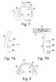
- FIG. 7is a front view of the metatarsal bone fixation device of FIG. 2 taken along line 7 - 7 of FIG. 5 ;
- FIG. 7Ais an enlarged front view of a portion of the metatarsal bone fixation device of FIG. 2 taken along circle 7 A of FIG. 7 , particularly showing attachment structures of an arm thereof;
- FIG. 7Bis an enlarged sectional view of a front portion of the metatarsal fixation device of FIG. 2 taken along line 7 B- 7 B of FIG. 7 ;
- FIG. 8is a front view of the metatarsal bone fixation device of FIG. 2 illustrating the manner in which the metatarsal bone fixation device flexes for attachment to a metatarsal head or to the metatarsal head and the metatarsal phalangeal joint capsule to the medial or lateral aspect of the metatarsal head;
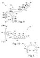
- FIG. 9is an oblique view of another embodiment of a metatarsal bone fixation device fashioned in accordance with the present principles wherein an attachment portion of the device is angled or offset relative to a longitudinal axis of a plate of the device;
- FIG. 10is a top view of the metatarsal bone fixation device of FIG. 9 ;
- FIG. 11is a front view of the metatarsal bone fixation device of FIG. 9 taken along line 11 - 11 of FIG. 10 ;
- FIG. 12is an oblique of another embodiment of a metatarsal bone fixation device fashioned in accordance with the present principles wherein an attachment portion of the device is angled or offset relative to a longitudinal axis of a plate of the device;
- FIG. 13is a top view of the metatarsal bone fixation device of FIG. 12 ;
- FIG. 14is a front view of the metatarsal bone fixation device of FIG. 12 taken along line 12 - 12 of FIG. 13 ;
- FIG. 15is an oblique view of another embodiment of a metatarsal bone fixation device fashioned in accordance with the present principles
- FIG. 16is a top view of the metatarsal bone fixation device of FIG. 15 ;
- FIG. 17is a front view of the metatarsal bone fixation device of FIG. 15 taken along line 17 - 17 of FIG. 16 ;
- FIG. 18is a top view of an another embodiment of a metatarsal bone fixation device fashioned in accordance with the present principles, an attachment portion of the device angled or offset relative to a longitudinal axis of a plate of the device;
- FIG. 19is a top view of an another embodiment of a metatarsal bone fixation device fashioned in accordance with the present principles, an attachment portion of the device angled or offset relative to a longitudinal axis of a plate of the device;
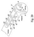
- FIG. 20is an oblique view of the metatarsal bone fixation device of FIG. 1 affixed to a metatarsal and, particularly to a diaphysis and epiphysis of the metatarsal for the stabilization of a metaphyseal fracture thereof, the arms of the attachment portion of the metatarsal bone fixation positioned about and onto the epiphysis, the jagged line representing a fracture/osteotomy;
- FIG. 21is an end view of an exemplary instrument for installing any embodiment of a metatarsal bone fixation device, the installation instrument depicted expanding the arms and attachment structures of the attachment portion of the metatarsal fixation device prior to affixation of the metatarsal bone fixation device onto the metatarsal head via jaws of the installation instrument;
- FIG. 22is an enlarged end view of the metatarsal head with a metatarsal bone fixation device engaging the metatarsal head with its attachment structures.
- FIG. 1there is depicted for purposes of illustration a diagram of the general bones of a human foot 10 particularly a right human foot as seen viewed the top.
- the human foothas tarsal bones or tarsals including the calcaneous C and the talus T, the metatarsal bones or metatarsals and phalange bones or phalanges.
- the present bone fixation devicemay be used for various bones of the body, it is especially configured for the fixation of a metatarsal. It is thus with respect to a metatarsal that the present invention will be described.
- FIGS. 1-8there is depicted several views of a bone fixation device generally designated 20.
- the bone fixation device 20is particularly suited for and is thus fashioned as a metatarsal fixation device 20 .
- the metatarsal bone fixation device 20is characterized by a plate 22 having an elongated portion 24 and a clamping portion 26 .
- the clamping portion or clamp 26is characterized by arms 28 and 30 that extend from lateral or transverse sides of a distal end (as implanted) of the elongated portion 24 .
- the arms 28 , 30initially extend transverse to the distal end of the elongated portion 24 then curve or arch downward and away from the end of the elongated portion 24 to generally form a U shape.
- the plate 22is composed of a generally rigid but resilient, biocompatible metal that is preferably, but not necessarily, approximately 1 mm thick.
- the underside of the plate 22 or the surface of the plate 22 that contacts the bone surfacemay include a slight radius from medial to lateral to match the contour of the bone such as discerned in FIG. 4A .
- the elongated portion 24 of the plate 22has an anchoring section fashioned as a plurality of threaded holes (holes 33 , 34 , 35 ) that extend along the longitudinal length of the elongated portion 24 from a proximate end 36 thereof towards a distal end thereof (i.e. the clamping portion 26 ).
- the anchoring sectionmay include more or less threaded holes with three threaded holes being preferred.
- the three threaded holes 33 , 34 , 35are depicted at one end of the elongated portion 24 arranged in linear orientation and evenly spaced. Other configurations, however, may be used and are contemplated.
- a single threaded hole 32is centered at the distal end of the plate 22 at the clamping portion 26 .
- the single or isolated hole 32is separated from the next hole 33 of the anchoring section by an appropriate distance (which in the case of a metatarsal, is approximately 10 mm).
- Each of the threaded holes 33 , 34 , 35 , 32is for receiving threaded bone screws when the device is implanted/attached. This is seen in FIG. 20 where bone screws 990 extend from the holes 32 , 33 , 34 , 35 , and into the bone when the device 20 is installed.
- the bone screws 990preferably have threaded shafts 991 that extend into and grip the bone.
- the threaded hole 32is shown in greater detail as exemplary of all of the threaded holes 32 , 33 , 34 , and 35 .
- the clamping portion 26is characterized by two arms 28 , 30 that project from lateral sides of the distal end of the elongated plate 24 .
- the arms 28 , 30project transverse from the lateral sides of the distal end of the elongated plate 24 then extend downwardly to generally form a U shape.
- the arm 28includes an attachment structure 39 on an inside surface thereof.
- the attachment structure 39is defined by a plurality of spikes or spike-like structures 38 a , 38 b , 38 c that project inward from the inside surface of the arm 28 .
- the spikes 38 a , 38 b , 38 care the same shape and size.
- the spikes 38 a , 38 b , 38 cprotrude 1 mm from the inner surface of the am 28 . It should be appreciated however, that the spikes of the attachment structure 39 may be shaped and sized differently if desired. Also, the spikes 38 a , 38 b , 38 c are preferably, but not necessarily, evenly spaced relative to each other beginning proximate an end of the arm 28 distal the elongated plate 24 . The spikes provide points of contact with the metatarsal head affording various points of fixation. The spikes 38 a , 38 b , 38 c are shaped and sized to grasp or clamp against, affix or attach to, a lateral side of a metatarsal head.
- the spikes 38 a , 38 b , 38 cgrasp, clamp or compress against a capsule or a capsule portion of the metatarsal joint which then affixes or attaches the capsule or capsule portion of the metatarsal joint to a lateral side of the metatarsal head, thereby facilitating realignment of the metatarsalsophalageal joint and respective digit.
- the arm 30includes an attachment structure 41 on an inside surface thereof in like manner as the attachment structure 39 of the arm 28 .
- the attachment structure 41is defined by a plurality of spikes or spike-like structures 40 a , 40 b , 40 c that project inward from the inside surface of the arm 30 .
- the spikes 40 a , 40 b , 40 care the same shape and size.
- the spikes 40 a , 40 b , 40 cprotrude 1 mm from the inner surface of the am 30 . It should be appreciated however, that the spikes of the attachment structure 41 may be shaped and sized differently if desired.
- the spikes 40 a , 40 b , 40 care preferably, but not necessarily, evenly spaced relative to each other beginning proximate an end of the arm 30 distal the elongated plate 24 .
- the spikesprovide points of contact with the metatarsal head affording various points of fixation.
- the spikes 40 a , 40 b , 40 care shaped and sized to grasp or clamp against, affix or attach to, lateral sides of a metatarsal head.
- the spikes 40 a , 40 b , 40 cgrasp, clamp or compress against a capsule or a capsule portion of the metatarsal joint which then affixes or attaches the capsule or capsule portion of the metatarsal joint to a lateral side of the metatarsal head, thereby facilitating realignment of the metatarsalsophalageal joint and respective digit.
- the arms 28 , 30are resilient or spring-like such that they return to their original shape after being spread, such as during implantation of the device.
- the resilient arms 28 , 30are configured and shaped to compress, grasp or clamp against or attach to the metatarsal head under their own natural resilient force.
- the attachment structures 39 , 41and, particularly the spikes 38 , 40 of the attachment structures 39 , 41 ) contact, compress and grasp or clamp onto the metatarsal head with or without clamping or securing of a capsule or capsule portion depending on whether the clamping portion 26 is used extracapsularly (with capsule securing) or intracapsularly (without capsule securing).
- the natural clamping position or state of the arms 28 , 30i.e.
- clamping portion 26is represented by the unbroken lines and a temporary expanded position or state of the arms 28 , 30 is represented by the broken lines.
- the arms 28 , 30are expanded during implantation of the device as per an instrument 950 illustrated in FIG. 21 which is described more fully below.
- the expanded positionis achieved by forcibly spreading the arms 28 , 30 as via the instrument 950 .
- the metatarsal fixation device 20is used where the metatarsal head or epiphysis is attached to the metatarsal diaphysis (bone shaft) along its original longitudinal axis such as shown in FIG. 20 where a fracture of the metaphysis of the metatarsal has been repaired through the use of the metatarsal fixation device 20 .
- the capsule and other metatarsal joint tissueis not shown.
- a modified metatarsal fixation deviceis used.
- the metatarsal fixation device 120is characterized by a plate 122 having an elongated portion 124 and a clamping portion 126 .
- the clamping portion or clamp 126is characterized by arms 128 and 130 that extend from lateral or transverse sides of a distal end (as implanted) of the elongated portion 124 .
- the arms 128 , 130initially extend transverse to the distal end of the elongated portion 124 then curve or arch downward and away from the end of the elongated portion 124 to generally form a U shape.
- the plate 122is composed of a generally rigid but resilient, biocompatible metal that is preferably, but not necessarily, approximately 1 mm thick.
- the underside of the plate 122 or the surface of the plate 122 that contacts the bone surfacemay include a slight radius from medial to lateral to match the contour of the bone such as shown in FIG. 4A with respect to the metatarsal fixation device 20 .
- the elongated portion 124 of the plate 122has an anchoring section fashioned as a plurality of threaded holes (holes 133 , 134 , 135 ) that extend along the longitudinal length of the elongated portion 124 from a proximate end 136 thereof towards a distal end thereof (i.e. the clamping portion 126 ).
- the anchoring sectionmay include more or less threaded holes with three threaded holes being preferred.
- the three threaded holes 133 , 134 , 135are depicted at one end of the elongated portion 124 arranged in linear orientation and evenly spaced. Other configurations, however, may be used and are contemplated.
- a single threaded hole 132is centered at the distal end of the plate 122 at the clamping portion 126 .
- the single or isolated hole 132is separated from the next hole 133 of the anchoring section by a crook or angled section 125 providing an appropriate distance (which in the case of a metatarsal, is approximately 10 mm).
- Each of the threaded holes 132 , 133 , 134 , 135are for receiving threaded bone screws when the device is implanted/attached in like manner as the metatarsal fixation device 20 shown in FIG. 20 .
- the threaded holes 132 , 133 , 134 , 135are like the threaded hole 32 shown in FIG. 4A .
- the clamping portion 126is characterized by two arms 128 , 130 that project from lateral sides of the distal end of the elongated plate 124 .
- the arms 128 , 130project transverse from the lateral sides of the distal end of the elongated plate 124 then extend downwardly to generally form a U shape.
- the arm 128includes an attachment structure 139 on an inside surface thereof.
- the attachment structure 139is defined by a plurality of spikes or spike-like structures 138 a , 138 b , 138 c that project inward from the inside surface of the arm 128 .
- the spikes 138 a , 138 b , 138 care the same shape and size.
- the spikes 138 a , 138 b , 138 cprotrude 1 mm from the inner surface of the am 128 . It should be appreciated however, that the spikes of the attachment structure 139 may be shaped and sized differently if desired. Also, the spikes 138 a , 138 b , 138 c are preferably, but not necessarily, evenly spaced relative to each other beginning proximate an end of the arm 128 distal the elongated plate 124 . The spikes provide points of contact with the metatarsal head affording various points of fixation.
- the spikes 138 a , 138 b , 138 care shaped and sized to grasp or clamp against, affix or attach to, a lateral side of a metatarsal head. Additionally, the spikes 138 a , 138 b , 138 c grasp, clamp or compress against a capsule or a capsule portion of the metatarsal joint which then affixes or attaches the capsule or capsule portion of the metatarsal joint to a lateral side of the metatarsal head, thereby facilitating realignment of the metatarsalsophalageal joint and respective digit.
- the arm 130includes an attachment structure 141 on an inside surface thereof in like manner as the attachment structure 139 of the arm 128 .
- the attachment structure 141is defined by a plurality of spikes or spike-like structures 140 a , 140 b , 140 c that project inward from the inside surface of the arm 130 .
- the spikes 140 a , 140 b , 140 care the same shape and size.
- the spikes 140 a , 140 b , 140 cprotrude 1 mm from the inner surface of the am 130 . It should be appreciated however, that the spikes of the attachment structure 141 may be shaped and sized differently if desired.
- the spikes 140 a , 140 b , 140 care preferably, but not necessarily, evenly spaced relative to each other beginning proximate an end of the arm 130 distal the elongated plate 124 .
- the spikesprovide points of contact with the metatarsal head affording various points of fixation.
- the spikes 140 a , 140 b , 140 care shaped and sized to grasp or clamp against, affix or attach to, a lateral side of a metatarsal head.
- the spikes 140 a , 140 b , 140 cgrasp, clamp or compress against a capsule or a capsule portion of the metatarsal joint which then affixes or attaches the capsule or capsule portion of the metatarsal joint to a lateral side of the metatarsal head, thereby facilitating realignment of the metatarsalsophalageal joint and respective digit.
- the arms 128 , 130are resilient or spring-like such that they return to their original shape after being spread, such as during implantation of the device.
- the resilient arms 128 , 130are configured and shaped to compress, grasp or clamp against or attach to lateral sides of the metatarsal head under their own natural resilient force.
- the attachment structures 139 , 141(and, particularly the spikes 138 , 140 of the attachment structures 139 , 141 ) contact, compress and grasp or clamp onto the metatarsal head with or without clamping or securing of a capsule or capsule portion depending on whether the clamping portion 126 is used extracapsularly (with capsule securing) or intracapsularly (without capsule securing). This is the same as that illustrated in FIG. 8 for the metatarsal fixation device 20 .
- the crook or angled section 125 of the plate 122provides an offset of the clamping portion 126 relative to the elongated portion 124 relative to a lateral side of the elongated portion 124 .
- the longitudinal axis of the fixed epiphysisis offset a given amount corresponding to the amount of offset provided by the crook 125 relative to the longitudinal axis of the diaphysis.
- the amount of offsetmay vary depending on the amount of offset required.
- plates 122may be made with different offsets or crooks 125 to accommodate desired outcomes.
- FIGS. 12-14there is depicted a metatarsal fixation device 220 fashioned in like manner to the metatarsal fixation device 120 of FIGS. 9-11 but with a crook or angled section 225 that projects from a lateral side of the elongated plate opposite to that of the metatarsal fixation device 120 .
- the metatarsal fixation device 220is used in cases where fixation of the epiphysis is intentionally not aligned with the original longitudinal axis of the diaphysis.
- the metatarsal fixation device 220is characterized by a plate 222 having an elongated portion 224 and a clamping portion 226 .
- the clamping portion or clamp 226is characterized by arms 228 and 230 that extend from lateral or transverse sides of a distal end (as implanted) of the elongated portion 224 . As seen in FIG. 14 , the arms 228 , 230 initially extend transverse to the distal end of the elongated portion 224 then curve or arch downward and away from the end of the elongated portion 224 to generally form a U shape.
- the plate 222is composed of a generally rigid but resilient, biocompatible metal that is preferably, but not necessarily, approximately 1 mm thick.
- the underside of the plate 222 or the surface of the plate 222 that contacts the bone surfacemay include a slight radius from medial to lateral to match the contour of the bone such as shown in FIG. 4A with respect to the metatarsal fixation device 20 .
- the elongated portion 224 of the plate 222has an anchoring section fashioned as a plurality of threaded holes (holes 233 , 234 , 235 ) that extend along the longitudinal length of the elongated portion 224 from a proximate end 236 thereof towards a distal end thereof (i.e. the clamping portion 226 ).
- the anchoring sectionmay include more or less threaded holes with three threaded holes being preferred.
- the three threaded holes 233 , 234 , 235are depicted at one end of the elongated portion 224 arranged in linear orientation and evenly spaced. Other configurations, however, may be used and are contemplated.
- a single threaded hole 232is centered at the distal end of the plate 222 at the clamping portion 226 .
- the single or isolated hole 232is separated from the next hole 233 of the anchoring section by a crook or angled section 225 providing an appropriate distance (which in the case of a metatarsal, is approximately 10 mm).
- Each of the threaded holes 232 , 233 , 234 , 235are for receiving threaded bone screws when the device is implanted/attached in like manner as the metatarsal fixation device 20 shown in FIG. 20 .
- the threaded holes 232 , 233 , 234 , 235are like the threaded hole 32 shown in FIG. 4A .
- the clamping portion 226is characterized by two arms 228 , 230 that project from lateral sides of the distal end of the elongated plate 224 .
- the arms 228 , 230project transverse from the lateral sides of the distal end of the elongated plate 224 then extend downwardly to generally form a U shape.
- the arm 228includes an attachment structure 239 on an inside surface thereof.
- the attachment structure 239is defined by a plurality of spikes or spike-like structures 238 a , 238 b , 238 c that project inward from the inside surface of the arm 228 .
- the spikes 238 a, 238 b, 238 care the same shape and size.
- the spikes 238 a , 238 b , 238 cprotrude 1 mm from the inner surface of the arm 228 . It should be appreciated however, that the spikes of the attachment structure 239 may be shaped and sized differently if desired. Also, the spikes 238 a , 238 b , 238 c are preferably, but not necessarily, evenly spaced relative to each other beginning proximate an end of the arm 228 distal the elongated plate 224 . The spikes provide points of contact with the metatarsal head affording various points of fixation.
- the spikes 238 a , 238 b , 238 care shaped and sized to grasp or clamp against, affix or attach to, a lateral side of a metatarsal head. Additionally, the spikes 238 a , 238 b , 238 c grasp, clamp or compress against a capsule or a capsule portion of the metatarsal joint which then affixes or attaches the capsule or capsule portion of the metatarsal joint to a lateral side of the metatarsal head, thereby facilitating realignment of the metatarsalsophalageal joint and respective digit.
- the arm 230includes an attachment structure 241 on an inside surface thereof in like manner as the attachment structure 239 of the arm 228 .
- the attachment structure 241is defined by a plurality of spikes or spike-like structures 240 a , 240 b , 240 c that project inward from the inside surface of the arm 230 .
- the spikes 240 a , 240 b , 240 care the same shape and size.
- the spikes 240 a , 240 b , 240 cprotrude 1 mm from the inner surface of the am 230 . It should be appreciated however, that the spikes of the attachment structure 241 may be shaped and sized differently if desired.
- the spikes 240 a , 240 b , 240 care preferably, but not necessarily, evenly spaced relative to each other beginning proximate an end of the arm 230 distal the elongated plate 224 .
- the spikesprovide points of contact with the metatarsal head affording various points of fixation.
- the spikes 240 a , 240 b , 240 care shaped and sized to grasp or clamp against, affix or attach to, a lateral side of a metatarsal head.
- the spikes 240 a , 240 b , 240 cgrasp, clamp or compress against a capsule or a capsule portion of the metatarsal joint which then affixes or attaches the capsule or capsule portion of the metatarsal joint to a lateral side of the metatarsal head, thereby facilitating realignment of the metatarsalsophalageal joint and respective digit.
- the arms 228 , 230are resilient or spring-like such that they return to their original shape after being spread, such as during implantation of the device.
- the resilient arms 228 , 230are configured and shaped to compress, grasp or clamp against or attach to lateral sides of the metatarsal head under their own natural resilient force.
- the attachment structures 239 , 241and, particularly the spikes 238 , 240 of the attachment structures 239 , 241 ) contact, compress and grasp or clamp onto the metatarsal head with or without clamping or securing of a capsule or capsule portion depending on whether the clamping portion 226 is used extracapsularly (with capsule securing) or intracapsularly (without capsule securing). This is the same as that illustrated in FIG. 8 for the metatarsal fixation device 20 .
- the crook or angled section 225 of the plate 222provides an offset of the clamping portion 226 relative to the elongated portion 224 relative to the lateral side of the elongated portion 224 opposite to the lateral side of the offset of the metatarsal fixation device 120 .
- the longitudinal axis of the fixed epiphysisis offset a given amount corresponding to the amount of offset provided by the crook 225 relative to the longitudinal axis of the diaphysis.
- the amount of offsetmay vary depending on the amount of offset required.
- plates 222may be made with different offsets or crooks 225 to accommodate desired outcomes.
- the metatarsal fixation devices 20 , 120 , and 220may be made in various sizes in order to accommodate variations in anatomy as well as use.
- the metatarsal fixation devices 20 , 120 , 220may come in various sizes for the various sizes of metatarsals both with respect to an individual and in general.
- Variations in the length and curvature of the respective elongated portions 24 , 124 , 224are contemplated as well as thickness, curvature and length of the respective arms thereof.
- Each arm thereofis thus sized appropriately for the particular bone. In the present metatarsal application, each arm may be approximately 2 mm wide. Referring to FIGS.
- a metatarsal fixation device 320there is depicted a variation in size for a metatarsal fixation device 320 , particularly in the size of the clamping portion 326 thereof in order to illustrate that the metatarsal fixation device (or other bone fixation device) may be fashioned having various dimensions.
- the clamping portion 326 of the bone fixation device 320provides a U shape that is wider than the U shape of the clamping portions 26 , 126 , 226 of the respective metatarsal fixation devices 20 , 120 , 220 .
- the various components and features of the bone fixation device 320that are the same or similar to the various components and features of the bone fixation devices 20 , 120 , 220 are labeled in like manner but in the three hundreds.
- FIGS. 18 and 19provide two further metatarsal fixation devices 420 and 520 each a variation in size of the two metatarsal fixation devices 120 and 220 respectively, and particularly, a variation in size of their respective clamping portions 426 , 526 .
- the various components and features of the metatarsal fixation devices 420 and 520 that are the same or similar to the various components and features of the bone fixation devices 120 and 220are labeled in like manner but in the four and five hundreds respectively.
- the bone fixation platemay also have variations in other parts not specifically shown herein such as variations in the dimensions of the elongated portion of the plate, such as length, width and hole spacing.
- the metatarsal fixation plate 22is shown implanted onto a fractured metaphysis of a metatarsal and thus joining or holding together the epiphysis to the diaphysis of the fractured metatarsal.
- the attachment structure 39 of the arm 28engages, contacts, grasps or clasps a portion of the epiphysis, particularly from a middle (e.g. upper) area of the epiphysis around to and extending about a lateral side thereof.
- the attachment structure 41 of the arm 30engages, contacts, grasps or clasps another portion of the epiphysis, particularly from the middle area of the epiphysis around to and extending about a medial side thereof.
- Bone screws 990are shown extending through the various threaded bores of the plate 22 and into the diaphysis and epiphysis. Particularly the threaded shafts 991 extend into the metatarsal bone while the heads 992 are retained on the plate 22 by the configuration of the bore holes.
- the arms 28 , 30are shown implanted in an intracapsular manner (i.e. under the capsule/soft tissue/ligament).
- the arms 28 , 30 and the associated attachment structures 39 , 41may additionally engage, contact, grasp or clasp a portion of the capsule and/or other tissue or ligament that may have become detached, cut and/or modified such as in the case of corrections to provide lengthening or releasing the soft tissue about the metatarsal. Tightening of the capsule or soft tissue is performed by removing a section or advancing the lax capsule/soft tissue from its original attachment and reattaching. The arms 28 , 30 would then be implanted in an extracapsular manner (i.e. over the capsule/soft tissue/ligament).
- FIG. 21an exemplary instrument 950 for implanting the present fixation device is shown.
- the instrument 950is formed by two curved handles 951 , 952 that are hinged at pivot 953 .
- the first handle 951has a distal portion 955 comprising a configured end 957 proximate the pivot 953 while the second handle 952 likewise has distal portion 954 having a configured end 956 proximate the pivot 953 .
- the configured end 957extends under and around the arm 30 in order to engage and hold the arm 30 .
- the configured end 956extends under and around the arm 28 in order to engage and hold the arm 28 .
- the configured ends 956 , 957allow the instrument or tool 950 to hold open and/or spread (bias) the arms 28 , 30 for implantation.
- the tool 950releases the arms 28 , 30 to allow them to spring or bias onto the metatarsal head MH (epiphysis/capsule) as depicted in FIG. 22 .
- Variations in the instrument 950are contemplated. The method of expanding the arms into place by the present instrument and thus grasping the metatarsal head through release of the expansion force can also be accomplished by additional methods.
- the elongated portion and the clamping portion of the present fixation deviceare preferably, but not necessarily, anatomically congruous to the associated metatarsal parts.
- the plateis attached to the metatarsal diaphysis with the series of locking screws along the elongated portion, and to the metatarsal head by one locking screw and the two attachment structures of the arms.
- the area of the plate between the series of holes of the elongated portion and the isolated hole of the clamping portionspans the metatarsal metaphysis mending an area of osteotomy or fracture.
Landscapes
- Health & Medical Sciences (AREA)
- Orthopedic Medicine & Surgery (AREA)
- Surgery (AREA)
- Life Sciences & Earth Sciences (AREA)
- Heart & Thoracic Surgery (AREA)
- Nuclear Medicine, Radiotherapy & Molecular Imaging (AREA)
- Engineering & Computer Science (AREA)
- Biomedical Technology (AREA)
- Neurology (AREA)
- Medical Informatics (AREA)
- Molecular Biology (AREA)
- Animal Behavior & Ethology (AREA)
- General Health & Medical Sciences (AREA)
- Public Health (AREA)
- Veterinary Medicine (AREA)
- Surgical Instruments (AREA)
Abstract
Description
Claims (16)
Priority Applications (7)
| Application Number | Priority Date | Filing Date | Title |
|---|---|---|---|
| US13/653,600US9101421B2 (en) | 2011-12-12 | 2012-10-17 | Metatarsal fixation device, system and method |
| US14/820,139US9566096B2 (en) | 2011-12-12 | 2015-08-06 | Metatarsal fixation device, system and method |
| US15/404,962US10064665B2 (en) | 2011-12-12 | 2017-01-12 | Metatarsal fixation device, system and method |
| US16/105,316US10653465B2 (en) | 2011-12-12 | 2018-08-20 | Metatarsal fixation device, system and method |
| US16/849,056US11033304B2 (en) | 2011-12-12 | 2020-04-15 | Metatarsal fixation device, system and method |
| US17/319,219US11648040B2 (en) | 2011-12-12 | 2021-05-13 | Metatarsal fixation device, system and method |
| US18/296,419US12076064B2 (en) | 2011-12-12 | 2023-04-06 | Metatarsal fixation device, system and method |
Applications Claiming Priority (2)
| Application Number | Priority Date | Filing Date | Title |
|---|---|---|---|
| US201161569605P | 2011-12-12 | 2011-12-12 | |
| US13/653,600US9101421B2 (en) | 2011-12-12 | 2012-10-17 | Metatarsal fixation device, system and method |
Related Child Applications (1)
| Application Number | Title | Priority Date | Filing Date |
|---|---|---|---|
| US14/820,139ContinuationUS9566096B2 (en) | 2011-12-12 | 2015-08-06 | Metatarsal fixation device, system and method |
Publications (2)
| Publication Number | Publication Date |
|---|---|
| US20130150853A1 US20130150853A1 (en) | 2013-06-13 |
| US9101421B2true US9101421B2 (en) | 2015-08-11 |
Family
ID=48572683
Family Applications (7)
| Application Number | Title | Priority Date | Filing Date |
|---|---|---|---|
| US13/653,600Active2033-01-11US9101421B2 (en) | 2011-12-12 | 2012-10-17 | Metatarsal fixation device, system and method |
| US14/820,139ActiveUS9566096B2 (en) | 2011-12-12 | 2015-08-06 | Metatarsal fixation device, system and method |
| US15/404,962ActiveUS10064665B2 (en) | 2011-12-12 | 2017-01-12 | Metatarsal fixation device, system and method |
| US16/105,316ActiveUS10653465B2 (en) | 2011-12-12 | 2018-08-20 | Metatarsal fixation device, system and method |
| US16/849,056ActiveUS11033304B2 (en) | 2011-12-12 | 2020-04-15 | Metatarsal fixation device, system and method |
| US17/319,219Active2033-02-07US11648040B2 (en) | 2011-12-12 | 2021-05-13 | Metatarsal fixation device, system and method |
| US18/296,419ActiveUS12076064B2 (en) | 2011-12-12 | 2023-04-06 | Metatarsal fixation device, system and method |
Family Applications After (6)
| Application Number | Title | Priority Date | Filing Date |
|---|---|---|---|
| US14/820,139ActiveUS9566096B2 (en) | 2011-12-12 | 2015-08-06 | Metatarsal fixation device, system and method |
| US15/404,962ActiveUS10064665B2 (en) | 2011-12-12 | 2017-01-12 | Metatarsal fixation device, system and method |
| US16/105,316ActiveUS10653465B2 (en) | 2011-12-12 | 2018-08-20 | Metatarsal fixation device, system and method |
| US16/849,056ActiveUS11033304B2 (en) | 2011-12-12 | 2020-04-15 | Metatarsal fixation device, system and method |
| US17/319,219Active2033-02-07US11648040B2 (en) | 2011-12-12 | 2021-05-13 | Metatarsal fixation device, system and method |
| US18/296,419ActiveUS12076064B2 (en) | 2011-12-12 | 2023-04-06 | Metatarsal fixation device, system and method |
Country Status (1)
| Country | Link |
|---|---|
| US (7) | US9101421B2 (en) |
Cited By (41)
| Publication number | Priority date | Publication date | Assignee | Title |
|---|---|---|---|---|
| US20150342653A1 (en)* | 2011-12-12 | 2015-12-03 | Solana Surgical, Llc | Metatarsal fixation device, system and method |
| US9622805B2 (en) | 2015-08-14 | 2017-04-18 | Treace Medical Concepts, Inc. | Bone positioning and preparing guide systems and methods |
| US9687250B2 (en) | 2015-01-07 | 2017-06-27 | Treace Medical Concepts, Inc. | Bone cutting guide systems and methods |
| US10342590B2 (en) | 2015-08-14 | 2019-07-09 | Treace Medical Concepts, Inc. | Tarsal-metatarsal joint procedure utilizing fulcrum |
| US10512470B1 (en) | 2016-08-26 | 2019-12-24 | Treace Medical Concepts, Inc. | Osteotomy procedure for correcting bone misalignment |
| US10524808B1 (en) | 2016-11-11 | 2020-01-07 | Treace Medical Concepts, Inc. | Devices and techniques for performing an osteotomy procedure on a first metatarsal to correct a bone misalignment |
| US10555757B2 (en) | 2014-07-15 | 2020-02-11 | Treace Medical Concepts, Inc. | Bone positioning and cutting system and method |
| US10575862B2 (en) | 2015-09-18 | 2020-03-03 | Treace Medical Concepts, Inc. | Joint spacer systems and methods |
| US10653467B2 (en) | 2015-05-06 | 2020-05-19 | Treace Medical Concepts, Inc. | Intra-osseous plate system and method |
| US10792081B2 (en) | 2014-08-28 | 2020-10-06 | Nextremity Solutions, Inc. | Bone fixation devices and methods |
| US10849631B2 (en) | 2015-02-18 | 2020-12-01 | Treace Medical Concepts, Inc. | Pivotable bone cutting guide useful for bone realignment and compression techniques |
| US10849663B2 (en) | 2015-07-14 | 2020-12-01 | Treace Medical Concepts, Inc. | Bone cutting guide systems and methods |
| US10874446B2 (en) | 2015-07-14 | 2020-12-29 | Treace Medical Concepts, Inc. | Bone positioning guide |
| US10939939B1 (en) | 2017-02-26 | 2021-03-09 | Treace Medical Concepts, Inc. | Fulcrum for tarsal-metatarsal joint procedure |
| US11000323B2 (en)* | 2018-06-01 | 2021-05-11 | Ortho Solutions Holdings Limited | Claw foot bone plate and plate inserter system with fixed and active compression, and method for its use |
| US11109900B2 (en)* | 2018-11-29 | 2021-09-07 | Gbr99 Ip, Llc | Extramedullary compression and fixation device, system and method |
| US11278337B2 (en) | 2015-08-14 | 2022-03-22 | Treace Medical Concepts, Inc. | Tarsal-metatarsal joint procedure utilizing fulcrum |
| US11583323B2 (en) | 2018-07-12 | 2023-02-21 | Treace Medical Concepts, Inc. | Multi-diameter bone pin for installing and aligning bone fixation plate while minimizing bone damage |
| US20230056989A1 (en)* | 2021-08-17 | 2023-02-23 | Edward Perez | Bone fixation devices, systems, and methods |
| US11596443B2 (en) | 2018-07-11 | 2023-03-07 | Treace Medical Concepts, Inc. | Compressor-distractor for angularly realigning bone portions |
| US11607250B2 (en) | 2019-02-13 | 2023-03-21 | Treace Medical Concepts, Inc. | Tarsal-metatarsal joint procedure utilizing compressor-distractor and instrument providing sliding surface |
| US11622797B2 (en) | 2020-01-31 | 2023-04-11 | Treace Medical Concepts, Inc. | Metatarsophalangeal joint preparation and metatarsal realignment for fusion |
| US11627954B2 (en) | 2019-08-07 | 2023-04-18 | Treace Medical Concepts, Inc. | Bi-planar instrument for bone cutting and joint realignment procedure |
| US11642124B2 (en) | 2020-06-16 | 2023-05-09 | Ortho Solutions Holdings Limited | Reinforced bridge superelastic bone compression staple and inserter system |
| USD1011524S1 (en) | 2022-02-23 | 2024-01-16 | Treace Medical Concepts, Inc. | Compressor-distractor for the foot |
| US11889998B1 (en) | 2019-09-12 | 2024-02-06 | Treace Medical Concepts, Inc. | Surgical pin positioning lock |
| US11890039B1 (en) | 2019-09-13 | 2024-02-06 | Treace Medical Concepts, Inc. | Multi-diameter K-wire for orthopedic applications |
| US11931106B2 (en) | 2019-09-13 | 2024-03-19 | Treace Medical Concepts, Inc. | Patient-specific surgical methods and instrumentation |
| US11980372B2 (en) | 2020-04-28 | 2024-05-14 | Trilliant Surgical, Llc | Osteotomy fixation device and related systems and methods |
| US11986251B2 (en) | 2019-09-13 | 2024-05-21 | Treace Medical Concepts, Inc. | Patient-specific osteotomy instrumentation |
| US12004789B2 (en) | 2020-05-19 | 2024-06-11 | Treace Medical Concepts, Inc. | Devices and techniques for treating metatarsus adductus |
| USD1051382S1 (en) | 2022-02-23 | 2024-11-12 | Treace Medical Concepts, Inc. | Lesser metatarsal cut guide |
| US12161371B2 (en) | 2021-01-18 | 2024-12-10 | Treace Medical Concepts, Inc. | Contoured bone plate with locking screw for bone compression, particularly across a tarsometatarsal joint |
| USD1057155S1 (en) | 2022-02-23 | 2025-01-07 | Treace Medical Concepts, Inc. | Lesser metatarsal cut guide with parallel cut faces |
| US12193683B2 (en) | 2021-05-20 | 2025-01-14 | Treace Medical Concepts, Inc. | Cut guide with integrated joint realignment features |
| USD1068077S1 (en) | 2023-02-08 | 2025-03-25 | Treace Medical Concepts, Inc. | Orthopedic rasp for preparing an intercuneiform joint |
| USD1068078S1 (en) | 2023-02-08 | 2025-03-25 | Treace Medical Concepts, Inc. | Handle for an orthopedic instrument |
| USD1075012S1 (en) | 2022-02-23 | 2025-05-13 | Treace Medical Concepts, Inc. | Metatarsal lateral release instrument |
| US12310603B2 (en) | 2021-02-18 | 2025-05-27 | Treace Medical Concepts, Inc. | System and technique for metatarsal realignment with reduced incision length |
| USD1079011S1 (en) | 2022-02-23 | 2025-06-10 | Treace Medical Concepts, Inc. | Metatarsal cut guide with parallel cut faces |
| US12440250B2 (en) | 2024-02-05 | 2025-10-14 | Treace Medical Concepts, Inc. | Multi-diameter K-wire for orthopedic applications |
Families Citing this family (21)
| Publication number | Priority date | Publication date | Assignee | Title |
|---|---|---|---|---|
| US8882816B2 (en)* | 2007-08-02 | 2014-11-11 | Proactive Orthopedics, Llc | Fixation and alignment device and method used in orthopaedic surgery |
| US9433452B2 (en)* | 2012-08-03 | 2016-09-06 | Nextremity Solutions, Llc | Bone fixation device and method |
| WO2015112991A1 (en)* | 2014-01-27 | 2015-07-30 | Dallis James | Implantable medical device for restoring alignment and stabilizing bone fractures |
| WO2015131106A1 (en) | 2014-02-27 | 2015-09-03 | Surgical Design Innovations | Bone fusion/fixation device and related systems and methods |
| US20150335365A1 (en)* | 2014-05-24 | 2015-11-26 | Neutin Orthopedics, LLC | Fixation device for a mau-type osteotomy procedure |
| PL231693B1 (en)* | 2014-09-12 | 2019-03-29 | Chm Spolka Z Ograniczona Odpowiedzialnoscia | Bone plate complex with the bone screw for stabilization of fractures |
| US10285689B2 (en)* | 2015-01-07 | 2019-05-14 | Biomet C.V. | Orthopedic implant for bone fixation |
| US20160206358A1 (en)* | 2015-01-21 | 2016-07-21 | Chunfeng Zhao | Orthopedic Fixation System and Method |
| TWI576085B (en)* | 2016-02-01 | 2017-04-01 | 愛派司生技股份有限公司 | A securing device for a long bone |
| JP6556075B2 (en)* | 2016-03-04 | 2019-08-07 | パナソニック株式会社 | Osteosynthesis parts |
| JP2018061622A (en)* | 2016-10-11 | 2018-04-19 | オプトス ピーエルシー | Fundus observation device |
| US11116555B2 (en)* | 2016-10-18 | 2021-09-14 | Tianjin Zhengtian Medical Instrument Co., Ltd | Wing-shaped angle steel plate and a bone shaft fixation system |
| CN106983552B (en)* | 2017-05-18 | 2023-06-20 | 长春圣博玛生物材料有限公司 | T-shaped buckling arm microplate device |
| CN106983553A (en)* | 2017-05-18 | 2017-07-28 | 长春圣博玛生物材料有限公司 | A kind of jeans button arm microplate device |
| WO2019221265A1 (en)* | 2018-05-17 | 2019-11-21 | Kisco株式会社 | Treatment tool |
| US12295589B2 (en) | 2019-12-12 | 2025-05-13 | Relja Innovations, Llc | Method, surgical apparatus, and surgical implant for minimally invasive surgical procedures |
| WO2022011060A1 (en)* | 2020-07-07 | 2022-01-13 | The General Hospital Corporation | 5th metatarsal compression fixation system |
| WO2022093132A1 (en)* | 2020-10-06 | 2022-05-05 | Mamur Teknoloji Sistemleri San. A.S. | A cooking device with touch sensitive slider |
| KR102309724B1 (en)* | 2020-12-31 | 2021-10-06 | 순천향대학교 산학협력단 | Fracture repair clip |
| US20230107021A1 (en)* | 2021-09-28 | 2023-04-06 | Kls Martin, Lp | Surgical Guides and Implants Having Periosteum Compressing Projections |
| US11883075B2 (en) | 2021-11-08 | 2024-01-30 | Relja Innovations, Llc | Device and surgical technique for foot surgery |
Citations (14)
| Publication number | Priority date | Publication date | Assignee | Title |
|---|---|---|---|---|
| US4651724A (en) | 1984-05-18 | 1987-03-24 | Technomed Gmk | Bone joining plate |
| JPH0312145A (en)* | 1989-06-12 | 1991-01-21 | Masayoshi Kishigami | Bone plate |
| US5674222A (en) | 1994-06-01 | 1997-10-07 | Synthes (U.S.A.) | Forked plate |
| US6283969B1 (en) | 2000-03-10 | 2001-09-04 | Wright Medical Technology, Inc. | Bone plating system |
| US6730090B2 (en) | 2000-02-01 | 2004-05-04 | Hand Innovations, Inc. | Fixation device for metaphyseal long bone fractures |
| US7229444B2 (en) | 2004-08-25 | 2007-06-12 | Howmedica Osteonics Corp. | Trochanteric cerclage plate |
| US7335204B2 (en)* | 2001-07-17 | 2008-02-26 | Tornier Sa | Osteosynthesis plate for the upper end of the arm bone |
| US20080119895A1 (en)* | 2006-11-20 | 2008-05-22 | Thierry Manceau | Locking bone plate with bushing anti-rotation feature |
| WO2009086402A1 (en)* | 2007-12-28 | 2009-07-09 | Pronto Products, Llc | Rib bone tissue clamp |
| US20090198277A1 (en) | 2007-12-28 | 2009-08-06 | Osteomed Spine, Inc. | Bone tissue fixation device and method |
| US20100069966A1 (en) | 2008-09-15 | 2010-03-18 | Alfredo Castaneda | Bone Plate System for Hand Fractures and Other Small Bones |
| US20110029025A1 (en) | 2009-07-31 | 2011-02-03 | Medoff Robert J | Locking pin plate assembly adapted for fracture fixation |
| US8603148B2 (en)* | 2010-05-07 | 2013-12-10 | Raymond B. Raven, III | System for treating bone fractures |
| US8906070B2 (en)* | 2005-10-25 | 2014-12-09 | Robert J. Medoff | Bone fixation device and method |
Family Cites Families (5)
| Publication number | Priority date | Publication date | Assignee | Title |
|---|---|---|---|---|
| FR2416683A1 (en)* | 1978-02-10 | 1979-09-07 | Judet Robert | IMPROVEMENTS TO OSTEO-SYNTHESIS DEVICES |
| US5634926A (en)* | 1995-04-25 | 1997-06-03 | Jobe; Richard P. | Surgical bone fixation apparatus |
| US5853413A (en)* | 1997-04-18 | 1998-12-29 | Bristol-Myers Squibb Company | Wrist fusion plate |
| WO2006091827A2 (en)* | 2005-02-25 | 2006-08-31 | Regents Of The University Of California | Device and template for canine humeral slide osteotomy |
| US9101421B2 (en)* | 2011-12-12 | 2015-08-11 | Solana Surgical, Llc | Metatarsal fixation device, system and method |
- 2012
- 2012-10-17USUS13/653,600patent/US9101421B2/enactiveActive
- 2015
- 2015-08-06USUS14/820,139patent/US9566096B2/enactiveActive
- 2017
- 2017-01-12USUS15/404,962patent/US10064665B2/enactiveActive
- 2018
- 2018-08-20USUS16/105,316patent/US10653465B2/enactiveActive
- 2020
- 2020-04-15USUS16/849,056patent/US11033304B2/enactiveActive
- 2021
- 2021-05-13USUS17/319,219patent/US11648040B2/enactiveActive
- 2023
- 2023-04-06USUS18/296,419patent/US12076064B2/enactiveActive
Patent Citations (14)
| Publication number | Priority date | Publication date | Assignee | Title |
|---|---|---|---|---|
| US4651724A (en) | 1984-05-18 | 1987-03-24 | Technomed Gmk | Bone joining plate |
| JPH0312145A (en)* | 1989-06-12 | 1991-01-21 | Masayoshi Kishigami | Bone plate |
| US5674222A (en) | 1994-06-01 | 1997-10-07 | Synthes (U.S.A.) | Forked plate |
| US6730090B2 (en) | 2000-02-01 | 2004-05-04 | Hand Innovations, Inc. | Fixation device for metaphyseal long bone fractures |
| US6283969B1 (en) | 2000-03-10 | 2001-09-04 | Wright Medical Technology, Inc. | Bone plating system |
| US7335204B2 (en)* | 2001-07-17 | 2008-02-26 | Tornier Sa | Osteosynthesis plate for the upper end of the arm bone |
| US7229444B2 (en) | 2004-08-25 | 2007-06-12 | Howmedica Osteonics Corp. | Trochanteric cerclage plate |
| US8906070B2 (en)* | 2005-10-25 | 2014-12-09 | Robert J. Medoff | Bone fixation device and method |
| US20080119895A1 (en)* | 2006-11-20 | 2008-05-22 | Thierry Manceau | Locking bone plate with bushing anti-rotation feature |
| WO2009086402A1 (en)* | 2007-12-28 | 2009-07-09 | Pronto Products, Llc | Rib bone tissue clamp |
| US20090198277A1 (en) | 2007-12-28 | 2009-08-06 | Osteomed Spine, Inc. | Bone tissue fixation device and method |
| US20100069966A1 (en) | 2008-09-15 | 2010-03-18 | Alfredo Castaneda | Bone Plate System for Hand Fractures and Other Small Bones |
| US20110029025A1 (en) | 2009-07-31 | 2011-02-03 | Medoff Robert J | Locking pin plate assembly adapted for fracture fixation |
| US8603148B2 (en)* | 2010-05-07 | 2013-12-10 | Raymond B. Raven, III | System for treating bone fractures |
Cited By (98)
| Publication number | Priority date | Publication date | Assignee | Title |
|---|---|---|---|---|
| US20230240731A1 (en)* | 2011-12-12 | 2023-08-03 | Wright Medical Technology, Inc. | Metatarsal fixation device, system and method |
| US9566096B2 (en)* | 2011-12-12 | 2017-02-14 | Solana Surgical, Llc | Metatarsal fixation device, system and method |
| US12076064B2 (en)* | 2011-12-12 | 2024-09-03 | Wright Medical Technology, Inc. | Metatarsal fixation device, system and method |
| US11033304B2 (en)* | 2011-12-12 | 2021-06-15 | Wright Medical Technology, Inc. | Metatarsal fixation device, system and method |
| US20150342653A1 (en)* | 2011-12-12 | 2015-12-03 | Solana Surgical, Llc | Metatarsal fixation device, system and method |
| US11648040B2 (en) | 2011-12-12 | 2023-05-16 | Wright Medical Technology, Inc. | Metatarsal fixation device, system and method |
| US10064665B2 (en) | 2011-12-12 | 2018-09-04 | Solana Surgical, Llc | Metatarsal fixation device, system and method |
| US20180353229A1 (en)* | 2011-12-12 | 2018-12-13 | Solana Surgical, Llc | Metatarsal fixation device, system and method |
| US10653465B2 (en)* | 2011-12-12 | 2020-05-19 | Wright Medical Technology, Inc. | Metatarsal fixation device, system and method |
| US12349941B2 (en) | 2014-07-15 | 2025-07-08 | Treace Medical Concepts, Inc. | Bone positioning and cutting system and method |
| US11771467B2 (en) | 2014-07-15 | 2023-10-03 | Treace Medical Concepts, Inc. | Bone positioning and cutting system and method |
| US10555757B2 (en) | 2014-07-15 | 2020-02-11 | Treace Medical Concepts, Inc. | Bone positioning and cutting system and method |
| US10945764B2 (en) | 2014-07-15 | 2021-03-16 | Treace Medical Concepts, Inc. | Bone positioning and cutting system and method |
| US11497528B2 (en) | 2014-07-15 | 2022-11-15 | Treace Medical Concepts, Inc. | Bone positioning and cutting system and method |
| US11147590B2 (en) | 2014-07-15 | 2021-10-19 | Treace Medical Concepts, Inc. | Bone positioning and cutting system and method |
| US11523845B2 (en) | 2014-07-15 | 2022-12-13 | Treace Medical Concepts, Inc. | Bone positioning and cutting system and method |
| US11937849B2 (en) | 2014-07-15 | 2024-03-26 | Treace Medical Concepts, Inc. | Bone positioning and cutting system and method |
| US10792081B2 (en) | 2014-08-28 | 2020-10-06 | Nextremity Solutions, Inc. | Bone fixation devices and methods |
| US11234743B2 (en) | 2014-08-28 | 2022-02-01 | Nextremity Solutions, Inc. | Bone fixation devices and methods |
| US10603046B2 (en) | 2015-01-07 | 2020-03-31 | Treace Medical Concepts, Inc. | Bone cutting guide systems and methods |
| US12268397B2 (en) | 2015-01-07 | 2025-04-08 | Treace Medical Concepts, Inc. | Bone cutting guide systems and methods |
| US10888335B2 (en) | 2015-01-07 | 2021-01-12 | Treace Medical Concepts, Inc. | Bone cutting guide systems and methods |
| US11786257B2 (en) | 2015-01-07 | 2023-10-17 | Treace Medical Concepts, Inc. | Bone cutting guide systems and methods |
| US9687250B2 (en) | 2015-01-07 | 2017-06-27 | Treace Medical Concepts, Inc. | Bone cutting guide systems and methods |
| US10561426B1 (en) | 2015-01-07 | 2020-02-18 | Treace Medical Concepts, Inc. | Bone cutting guide systems and methods |
| US10849631B2 (en) | 2015-02-18 | 2020-12-01 | Treace Medical Concepts, Inc. | Pivotable bone cutting guide useful for bone realignment and compression techniques |
| US11844533B2 (en) | 2015-02-18 | 2023-12-19 | Treace Medical Concepts, Inc. | Pivotable bone cutting guide useful for bone realignment and compression techniques |
| US12396771B2 (en) | 2015-05-06 | 2025-08-26 | Treace Medical Concepts, Inc. | Intra-osseous plate system and method |
| US10653467B2 (en) | 2015-05-06 | 2020-05-19 | Treace Medical Concepts, Inc. | Intra-osseous plate system and method |
| US11426219B2 (en) | 2015-05-06 | 2022-08-30 | Treace Medical Concepts, Inc. | Intra-osseous plate system and method |
| US11969193B2 (en) | 2015-05-06 | 2024-04-30 | Treace Medical Concepts, Inc. | Intra-osseous plate system and method |
| US11185359B2 (en) | 2015-07-14 | 2021-11-30 | Treace Medical Concepts, Inc. | Bone positioning guide |
| US11116558B2 (en) | 2015-07-14 | 2021-09-14 | Treace Medical Concepts, Inc. | Bone positioning guide |
| US12102368B2 (en) | 2015-07-14 | 2024-10-01 | Treace Medical Concepts, Inc. | Bone positioning guide |
| US10335220B2 (en) | 2015-07-14 | 2019-07-02 | Treace Medical Concepts, Inc. | Bone positioning guide |
| US9936994B2 (en) | 2015-07-14 | 2018-04-10 | Treace Medical Concepts, Inc. | Bone positioning guide |
| US10849663B2 (en) | 2015-07-14 | 2020-12-01 | Treace Medical Concepts, Inc. | Bone cutting guide systems and methods |
| US11602386B2 (en) | 2015-07-14 | 2023-03-14 | Treace Medical Concepts, Inc. | Bone positioning guide |
| US11950819B2 (en) | 2015-07-14 | 2024-04-09 | Treace Medical Concepts, Inc. | Bone positioning guide |
| US11963703B2 (en) | 2015-07-14 | 2024-04-23 | Treace Medical Concepts, Inc. | Bone cutting guide systems and methods |
| US10874446B2 (en) | 2015-07-14 | 2020-12-29 | Treace Medical Concepts, Inc. | Bone positioning guide |
| US9622805B2 (en) | 2015-08-14 | 2017-04-18 | Treace Medical Concepts, Inc. | Bone positioning and preparing guide systems and methods |
| US11690659B2 (en) | 2015-08-14 | 2023-07-04 | Treace Medical Concepts, Inc. | Tarsal-metatarsal joint procedure utilizing fulcrum |
| US11413081B2 (en) | 2015-08-14 | 2022-08-16 | Treace Medical Concepts, Inc. | Tarsal-metatarsal joint procedure utilizing fulcrum |
| US11911085B2 (en) | 2015-08-14 | 2024-02-27 | Treace Medical Concepts, Inc. | Bone positioning and preparing guide systems and methods |
| US10045807B2 (en) | 2015-08-14 | 2018-08-14 | Treace Medical Concepts, Inc. | Bone positioning and preparing guide systems and methods |
| US11278337B2 (en) | 2015-08-14 | 2022-03-22 | Treace Medical Concepts, Inc. | Tarsal-metatarsal joint procedure utilizing fulcrum |
| US11602387B2 (en) | 2015-08-14 | 2023-03-14 | Treace Medical Concepts, Inc. | Bone positioning and preparing guide systems and methods |
| US11039873B2 (en) | 2015-08-14 | 2021-06-22 | Treace Medical Concepts, Inc. | Bone positioning and preparing guide systems and methods |
| US10849670B2 (en) | 2015-08-14 | 2020-12-01 | Treace Medical Concepts, Inc. | Bone positioning and preparing guide systems and methods |
| US11213333B2 (en) | 2015-08-14 | 2022-01-04 | Treace Medical Concepts, Inc. | Bone positioning and preparing guide systems and methods |
| US12274481B2 (en) | 2015-08-14 | 2025-04-15 | Treace Medical Concepts, Inc. | Bone positioning and preparing guide systems and methods |
| US10342590B2 (en) | 2015-08-14 | 2019-07-09 | Treace Medical Concepts, Inc. | Tarsal-metatarsal joint procedure utilizing fulcrum |
| US12268428B2 (en) | 2015-08-14 | 2025-04-08 | Treace Medical Concepts, Inc. | Tarsal-metatarsal joint procedure utilizing fulcrum |
| US11771443B2 (en) | 2015-09-18 | 2023-10-03 | Treace Medical Concepts, Inc. | Joint spacer systems and methods |
| US10575862B2 (en) | 2015-09-18 | 2020-03-03 | Treace Medical Concepts, Inc. | Joint spacer systems and methods |
| US11648019B2 (en) | 2015-09-18 | 2023-05-16 | Treace Medical Concepts, Inc. | Joint spacer systems and methods |
| US12349927B2 (en) | 2015-09-18 | 2025-07-08 | Treace Medical Concepts, Inc. | Joint spacer systems and methods |
| US10512470B1 (en) | 2016-08-26 | 2019-12-24 | Treace Medical Concepts, Inc. | Osteotomy procedure for correcting bone misalignment |
| US11076863B1 (en) | 2016-08-26 | 2021-08-03 | Treace Medical Concepts, Inc. | Osteotomy procedure for correcting bone misalignment |
| US11931047B2 (en) | 2016-08-26 | 2024-03-19 | Treace Medical Concepts, Inc. | Osteotomy procedure for correcting bone misalignment |
| US10524808B1 (en) | 2016-11-11 | 2020-01-07 | Treace Medical Concepts, Inc. | Devices and techniques for performing an osteotomy procedure on a first metatarsal to correct a bone misalignment |
| US10582936B1 (en) | 2016-11-11 | 2020-03-10 | Treace Medical Concepts, Inc. | Devices and techniques for performing an osteotomy procedure on a first metatarsal to correct a bone misalignment |
| US11364037B2 (en) | 2016-11-11 | 2022-06-21 | Treace Medical Concepts, Inc. | Techniques for performing an osteotomy procedure on bone to correct a bone misalignment |
| US12414779B2 (en) | 2016-11-11 | 2025-09-16 | Treace Medical Concepts, Inc. | Devices and techniques for performing an osteotomy procedure on a first metatarsal to correct a bone misalignment |
| US10939939B1 (en) | 2017-02-26 | 2021-03-09 | Treace Medical Concepts, Inc. | Fulcrum for tarsal-metatarsal joint procedure |
| US12357347B2 (en) | 2017-02-26 | 2025-07-15 | Treace Medical Concepts, Inc. | Fulcrum for tarsal-metatarsal joint procedure |
| US11000323B2 (en)* | 2018-06-01 | 2021-05-11 | Ortho Solutions Holdings Limited | Claw foot bone plate and plate inserter system with fixed and active compression, and method for its use |
| US11596443B2 (en) | 2018-07-11 | 2023-03-07 | Treace Medical Concepts, Inc. | Compressor-distractor for angularly realigning bone portions |
| US11583323B2 (en) | 2018-07-12 | 2023-02-21 | Treace Medical Concepts, Inc. | Multi-diameter bone pin for installing and aligning bone fixation plate while minimizing bone damage |
| US11109900B2 (en)* | 2018-11-29 | 2021-09-07 | Gbr99 Ip, Llc | Extramedullary compression and fixation device, system and method |
| US11607250B2 (en) | 2019-02-13 | 2023-03-21 | Treace Medical Concepts, Inc. | Tarsal-metatarsal joint procedure utilizing compressor-distractor and instrument providing sliding surface |
| US12279794B2 (en) | 2019-02-13 | 2025-04-22 | Treace Medical Concepts, Inc. | Tarsal-metatarsal joint procedure utilizing compressor-distractor and instrument providing sliding surface |
| US12251091B2 (en) | 2019-08-07 | 2025-03-18 | Treace Medical Concepts, Inc. | Bi-planar instrument for bone cutting and joint realignment procedure |
| US11627954B2 (en) | 2019-08-07 | 2023-04-18 | Treace Medical Concepts, Inc. | Bi-planar instrument for bone cutting and joint realignment procedure |
| US11889998B1 (en) | 2019-09-12 | 2024-02-06 | Treace Medical Concepts, Inc. | Surgical pin positioning lock |
| US11931106B2 (en) | 2019-09-13 | 2024-03-19 | Treace Medical Concepts, Inc. | Patient-specific surgical methods and instrumentation |
| US11986251B2 (en) | 2019-09-13 | 2024-05-21 | Treace Medical Concepts, Inc. | Patient-specific osteotomy instrumentation |
| US11890039B1 (en) | 2019-09-13 | 2024-02-06 | Treace Medical Concepts, Inc. | Multi-diameter K-wire for orthopedic applications |
| US11622797B2 (en) | 2020-01-31 | 2023-04-11 | Treace Medical Concepts, Inc. | Metatarsophalangeal joint preparation and metatarsal realignment for fusion |
| US12364522B2 (en) | 2020-01-31 | 2025-07-22 | Treace Medical Concepts, Inc. | Metatarsophalangeal joint preparation and metatarsal realignment for fusion |
| US11980372B2 (en) | 2020-04-28 | 2024-05-14 | Trilliant Surgical, Llc | Osteotomy fixation device and related systems and methods |
| US12396770B2 (en) | 2020-05-19 | 2025-08-26 | Treace Medical Concepts, Inc. | Devices and techniques for treating metatarsus adductus |
| US12004789B2 (en) | 2020-05-19 | 2024-06-11 | Treace Medical Concepts, Inc. | Devices and techniques for treating metatarsus adductus |
| US11642124B2 (en) | 2020-06-16 | 2023-05-09 | Ortho Solutions Holdings Limited | Reinforced bridge superelastic bone compression staple and inserter system |
| US12161371B2 (en) | 2021-01-18 | 2024-12-10 | Treace Medical Concepts, Inc. | Contoured bone plate with locking screw for bone compression, particularly across a tarsometatarsal joint |
| US12310603B2 (en) | 2021-02-18 | 2025-05-27 | Treace Medical Concepts, Inc. | System and technique for metatarsal realignment with reduced incision length |
| US12193683B2 (en) | 2021-05-20 | 2025-01-14 | Treace Medical Concepts, Inc. | Cut guide with integrated joint realignment features |
| US12343050B2 (en) | 2021-08-17 | 2025-07-01 | Ps Ortho Llc | Bone fixation devices, systems, and methods |
| US20230056989A1 (en)* | 2021-08-17 | 2023-02-23 | Edward Perez | Bone fixation devices, systems, and methods |
| USD1079011S1 (en) | 2022-02-23 | 2025-06-10 | Treace Medical Concepts, Inc. | Metatarsal cut guide with parallel cut faces |
| USD1011524S1 (en) | 2022-02-23 | 2024-01-16 | Treace Medical Concepts, Inc. | Compressor-distractor for the foot |
| USD1075012S1 (en) | 2022-02-23 | 2025-05-13 | Treace Medical Concepts, Inc. | Metatarsal lateral release instrument |
| USD1057155S1 (en) | 2022-02-23 | 2025-01-07 | Treace Medical Concepts, Inc. | Lesser metatarsal cut guide with parallel cut faces |
| USD1051382S1 (en) | 2022-02-23 | 2024-11-12 | Treace Medical Concepts, Inc. | Lesser metatarsal cut guide |
| USD1068078S1 (en) | 2023-02-08 | 2025-03-25 | Treace Medical Concepts, Inc. | Handle for an orthopedic instrument |
| USD1068077S1 (en) | 2023-02-08 | 2025-03-25 | Treace Medical Concepts, Inc. | Orthopedic rasp for preparing an intercuneiform joint |
| US12440250B2 (en) | 2024-02-05 | 2025-10-14 | Treace Medical Concepts, Inc. | Multi-diameter K-wire for orthopedic applications |
Also Published As
| Publication number | Publication date |
|---|---|
| US20210267649A1 (en) | 2021-09-02 |
| US10064665B2 (en) | 2018-09-04 |
| US10653465B2 (en) | 2020-05-19 |
| US20200237417A1 (en) | 2020-07-30 |
| US20150342653A1 (en) | 2015-12-03 |
| US20130150853A1 (en) | 2013-06-13 |
| US11648040B2 (en) | 2023-05-16 |
| US11033304B2 (en) | 2021-06-15 |
| US20230240731A1 (en) | 2023-08-03 |
| US9566096B2 (en) | 2017-02-14 |
| US20180353229A1 (en) | 2018-12-13 |
| US12076064B2 (en) | 2024-09-03 |
| US20170181778A1 (en) | 2017-06-29 |
Similar Documents
| Publication | Publication Date | Title |
|---|---|---|
| US12076064B2 (en) | Metatarsal fixation device, system and method | |
| US11660131B2 (en) | Bone fusion/fixation device and related systems and methods | |
| US8784457B2 (en) | Implant for correcting skeletal mechanics | |
| US12290294B2 (en) | Bone fixation assembly, implants and methods of use | |
| US9814474B2 (en) | Resection guides, implants and methods | |
| US6123709A (en) | Bone buttress plate and method of using same | |
| US9107715B2 (en) | Fixation plate for use in the lapidus approach | |
| US9433452B2 (en) | Bone fixation device and method | |
| US9949773B2 (en) | Orthopedic bone plate and locking tab apparatus and method of use | |
| US20220183680A1 (en) | Bone clip with resilient arm for proximal compression | |
| US20160151165A1 (en) | Correction of first ray deformity | |
| US20120016366A1 (en) | Proximal Radius Locking Plate | |
| US20250143758A1 (en) | Fracture plating systems | |
| US20240058042A1 (en) | Surgical osteotomy fixation devices | |
| Lombardo | The improved Keller arthroplasty | |
| Derner | Pes Cavovarus Surgery |
Legal Events
| Date | Code | Title | Description |
|---|---|---|---|
| AS | Assignment | Owner name:SOLANA SURGICAL, LLC, TENNESSEE Free format text:ASSIGNMENT OF ASSIGNORS INTEREST;ASSIGNOR:BLACKLIDGE, DOUGLAS K., DR.;REEL/FRAME:032089/0416 Effective date:20121029 | |
| STCF | Information on status: patent grant | Free format text:PATENTED CASE | |
| AS | Assignment | Owner name:MIDCAP FINANCIAL TRUST, AS AGENT, MARYLAND Free format text:SECURITY INTEREST;ASSIGNOR:SOLANA SURGICAL, LLC;REEL/FRAME:040853/0938 Effective date:20161223 | |
| MAFP | Maintenance fee payment | Free format text:PAYMENT OF MAINTENANCE FEE, 4TH YEAR, LARGE ENTITY (ORIGINAL EVENT CODE: M1551); ENTITY STATUS OF PATENT OWNER: LARGE ENTITY Year of fee payment:4 | |
| AS | Assignment | Owner name:WRIGHT MEDICAL TECHNOLOGY, INC., TENNESSEE Free format text:ASSIGNMENT OF ASSIGNORS INTEREST;ASSIGNOR:SOLANA SURGICAL;REEL/FRAME:051397/0755 Effective date:20191213 | |
| AS | Assignment | Owner name:WRIGHT MEDICAL TECHNOLOGY, INC., TENNESSEE Free format text:RELEASE BY SECURED PARTY;ASSIGNOR:MIDCAP FUNDING IV TRUST;REEL/FRAME:054480/0001 Effective date:20201112 Owner name:WRIGHT MEDICAL GROUP, INC., TENNESSEE Free format text:RELEASE BY SECURED PARTY;ASSIGNOR:MIDCAP FUNDING IV TRUST;REEL/FRAME:054480/0001 Effective date:20201112 Owner name:WRIGHT MEDICAL GROUP N.V., NETHERLANDS Free format text:RELEASE BY SECURED PARTY;ASSIGNOR:MIDCAP FUNDING IV TRUST;REEL/FRAME:054480/0001 Effective date:20201112 Owner name:BIOMIMETIC THERAPEUTICS CANADA, INC., TENNESSEE Free format text:RELEASE BY SECURED PARTY;ASSIGNOR:MIDCAP FUNDING IV TRUST;REEL/FRAME:054480/0001 Effective date:20201112 Owner name:BIOMIMETIC THERAPEUTICS, LLC, TENNESSEE Free format text:RELEASE BY SECURED PARTY;ASSIGNOR:MIDCAP FUNDING IV TRUST;REEL/FRAME:054480/0001 Effective date:20201112 Owner name:TROOPER HOLDINGS INC., MINNESOTA Free format text:RELEASE BY SECURED PARTY;ASSIGNOR:MIDCAP FUNDING IV TRUST;REEL/FRAME:054480/0001 Effective date:20201112 Owner name:SOLANA SURGICAL, LLC, TENNESSEE Free format text:RELEASE BY SECURED PARTY;ASSIGNOR:MIDCAP FUNDING IV TRUST;REEL/FRAME:054480/0001 Effective date:20201112 Owner name:TORNIER US HOLDINGS, INC., MINNESOTA Free format text:RELEASE BY SECURED PARTY;ASSIGNOR:MIDCAP FUNDING IV TRUST;REEL/FRAME:054480/0001 Effective date:20201112 Owner name:WRIGHT MEDICAL CAPITAL, INC., TENNESSEE Free format text:RELEASE BY SECURED PARTY;ASSIGNOR:MIDCAP FUNDING IV TRUST;REEL/FRAME:054480/0001 Effective date:20201112 Owner name:BIOMIMETIC THERAPEUTICS USA, INC., TENNESSEE Free format text:RELEASE BY SECURED PARTY;ASSIGNOR:MIDCAP FUNDING IV TRUST;REEL/FRAME:054480/0001 Effective date:20201112 Owner name:ORTHOHELIX SURGICAL DESIGNS, INC., MINNESOTA Free format text:RELEASE BY SECURED PARTY;ASSIGNOR:MIDCAP FUNDING IV TRUST;REEL/FRAME:054480/0001 Effective date:20201112 Owner name:INBONE TECHNOLOGIES, INC., TENNESSEE Free format text:RELEASE BY SECURED PARTY;ASSIGNOR:MIDCAP FUNDING IV TRUST;REEL/FRAME:054480/0001 Effective date:20201112 Owner name:TORNIER, INC., MINNESOTA Free format text:RELEASE BY SECURED PARTY;ASSIGNOR:MIDCAP FUNDING IV TRUST;REEL/FRAME:054480/0001 Effective date:20201112 Owner name:WRIGHT MEDICAL GROUP INTELLECTUAL PROPERTY, INC., TENNESSEE Free format text:RELEASE BY SECURED PARTY;ASSIGNOR:MIDCAP FUNDING IV TRUST;REEL/FRAME:054480/0001 Effective date:20201112 Owner name:WHITE BOX ORTHOPEDICS, LLC, TENNESSEE Free format text:RELEASE BY SECURED PARTY;ASSIGNOR:MIDCAP FUNDING IV TRUST;REEL/FRAME:054480/0001 Effective date:20201112 Owner name:ORTHOPRO, L.L.C., TENNESSEE Free format text:RELEASE BY SECURED PARTY;ASSIGNOR:MIDCAP FUNDING IV TRUST;REEL/FRAME:054480/0001 Effective date:20201112 | |
| MAFP | Maintenance fee payment | Free format text:PAYMENT OF MAINTENANCE FEE, 8TH YEAR, LARGE ENTITY (ORIGINAL EVENT CODE: M1552); ENTITY STATUS OF PATENT OWNER: LARGE ENTITY Year of fee payment:8 |