US9101403B2 - Bone anchoring element and stabilization device for bones, in particular for the spinal column - Google Patents
Bone anchoring element and stabilization device for bones, in particular for the spinal columnDownload PDFInfo
- Publication number
- US9101403B2 US9101403B2US12/550,654US55065409AUS9101403B2US 9101403 B2US9101403 B2US 9101403B2US 55065409 AUS55065409 AUS 55065409AUS 9101403 B2US9101403 B2US 9101403B2
- Authority
- US
- United States
- Prior art keywords
- leg
- legs
- receiving part
- bone
- bone anchoring
- Prior art date
- Legal status (The legal status is an assumption and is not a legal conclusion. Google has not performed a legal analysis and makes no representation as to the accuracy of the status listed.)
- Active, expires
Links
- 238000004873anchoringMethods0.000titleclaimsabstractdescription105
- 210000000988bone and boneAnatomy0.000titleclaimsabstractdescription102
- 230000006641stabilisationEffects0.000titleclaimsabstractdescription65
- 238000011105stabilizationMethods0.000titleclaimsabstractdescription65
- 238000000034methodMethods0.000claims5
- 230000004308accommodationEffects0.000abstract1
- 238000010008shearingMethods0.000description7
- 239000000463materialSubstances0.000description6
- 239000004696Poly ether ether ketoneSubstances0.000description4
- 238000005452bendingMethods0.000description4
- JUPQTSLXMOCDHR-UHFFFAOYSA-Nbenzene-1,4-diol;bis(4-fluorophenyl)methanoneChemical compoundOC1=CC=C(O)C=C1.C1=CC(F)=CC=C1C(=O)C1=CC=C(F)C=C1JUPQTSLXMOCDHR-UHFFFAOYSA-N0.000description4
- 238000010276constructionMethods0.000description4
- 229910052751metalInorganic materials0.000description4
- 239000002184metalSubstances0.000description4
- 229920002530polyetherether ketonePolymers0.000description4
- 230000006835compressionEffects0.000description3
- 238000007906compressionMethods0.000description3
- 239000000806elastomerSubstances0.000description3
- 229920001971elastomerPolymers0.000description3
- RTAQQCXQSZGOHL-UHFFFAOYSA-NTitaniumChemical compound[Ti]RTAQQCXQSZGOHL-UHFFFAOYSA-N0.000description2
- 230000006378damageEffects0.000description2
- 230000004048modificationEffects0.000description2
- 238000012986modificationMethods0.000description2
- HLXZNVUGXRDIFK-UHFFFAOYSA-Nnickel titaniumChemical compound[Ti].[Ti].[Ti].[Ti].[Ti].[Ti].[Ti].[Ti].[Ti].[Ti].[Ti].[Ni].[Ni].[Ni].[Ni].[Ni].[Ni].[Ni].[Ni].[Ni].[Ni].[Ni].[Ni].[Ni].[Ni]HLXZNVUGXRDIFK-UHFFFAOYSA-N0.000description2
- 229910001000nickel titaniumInorganic materials0.000description2
- 239000004033plasticSubstances0.000description2
- 229920003023plasticPolymers0.000description2
- 229920001692polycarbonate urethanePolymers0.000description2
- 230000000087stabilizing effectEffects0.000description2
- 239000010935stainless steelSubstances0.000description2
- 229910001220stainless steelInorganic materials0.000description2
- 229910052719titaniumInorganic materials0.000description2
- 239000010936titaniumSubstances0.000description2
- OKTJSMMVPCPJKN-UHFFFAOYSA-NCarbonChemical compound[C]OKTJSMMVPCPJKN-UHFFFAOYSA-N0.000description1
- 229920000049Carbon (fiber)Polymers0.000description1
- 229910001069Ti alloyInorganic materials0.000description1
- 210000003484anatomyAnatomy0.000description1
- 230000000903blocking effectEffects0.000description1
- 229910052799carbonInorganic materials0.000description1
- 239000004917carbon fiberSubstances0.000description1
- 239000011248coating agentSubstances0.000description1
- 238000000576coating methodMethods0.000description1
- 238000013016dampingMethods0.000description1
- 230000007850degenerationEffects0.000description1
- 230000001747exhibiting effectEffects0.000description1
- 229920002457flexible plasticPolymers0.000description1
- 230000004927fusionEffects0.000description1
- 239000007943implantSubstances0.000description1
- 238000003780insertionMethods0.000description1
- 230000037431insertionEffects0.000description1
- 229910001092metal group alloyInorganic materials0.000description1
- VNWKTOKETHGBQD-UHFFFAOYSA-NmethaneChemical compoundCVNWKTOKETHGBQD-UHFFFAOYSA-N0.000description1
- -1polysiloxanePolymers0.000description1
- 229920001296polysiloxanePolymers0.000description1
- 229920002635polyurethanePolymers0.000description1
- 239000004814polyurethaneSubstances0.000description1
- 239000007787solidSubstances0.000description1
Images


Classifications
- A—HUMAN NECESSITIES
- A61—MEDICAL OR VETERINARY SCIENCE; HYGIENE
- A61B—DIAGNOSIS; SURGERY; IDENTIFICATION
- A61B17/00—Surgical instruments, devices or methods
- A61B17/56—Surgical instruments or methods for treatment of bones or joints; Devices specially adapted therefor
- A61B17/58—Surgical instruments or methods for treatment of bones or joints; Devices specially adapted therefor for osteosynthesis, e.g. bone plates, screws or setting implements
- A61B17/68—Internal fixation devices, including fasteners and spinal fixators, even if a part thereof projects from the skin
- A61B17/70—Spinal positioners or stabilisers, e.g. stabilisers comprising fluid filler in an implant
- A61B17/7001—Screws or hooks combined with longitudinal elements which do not contact vertebrae
- A61B17/7035—Screws or hooks, wherein a rod-clamping part and a bone-anchoring part can pivot relative to each other
- A61B17/7037—Screws or hooks, wherein a rod-clamping part and a bone-anchoring part can pivot relative to each other wherein pivoting is blocked when the rod is clamped
- A—HUMAN NECESSITIES
- A61—MEDICAL OR VETERINARY SCIENCE; HYGIENE
- A61B—DIAGNOSIS; SURGERY; IDENTIFICATION
- A61B17/00—Surgical instruments, devices or methods
- A61B17/56—Surgical instruments or methods for treatment of bones or joints; Devices specially adapted therefor
- A61B17/58—Surgical instruments or methods for treatment of bones or joints; Devices specially adapted therefor for osteosynthesis, e.g. bone plates, screws or setting implements
- A61B17/68—Internal fixation devices, including fasteners and spinal fixators, even if a part thereof projects from the skin
- A61B17/70—Spinal positioners or stabilisers, e.g. stabilisers comprising fluid filler in an implant
- A—HUMAN NECESSITIES
- A61—MEDICAL OR VETERINARY SCIENCE; HYGIENE
- A61F—FILTERS IMPLANTABLE INTO BLOOD VESSELS; PROSTHESES; DEVICES PROVIDING PATENCY TO, OR PREVENTING COLLAPSING OF, TUBULAR STRUCTURES OF THE BODY, e.g. STENTS; ORTHOPAEDIC, NURSING OR CONTRACEPTIVE DEVICES; FOMENTATION; TREATMENT OR PROTECTION OF EYES OR EARS; BANDAGES, DRESSINGS OR ABSORBENT PADS; FIRST-AID KITS
- A61F2/00—Filters implantable into blood vessels; Prostheses, i.e. artificial substitutes or replacements for parts of the body; Appliances for connecting them with the body; Devices providing patency to, or preventing collapsing of, tubular structures of the body, e.g. stents
- A61F2/02—Prostheses implantable into the body
- A61F2/30—Joints
- A61F2/44—Joints for the spine, e.g. vertebrae, spinal discs
- A—HUMAN NECESSITIES
- A61—MEDICAL OR VETERINARY SCIENCE; HYGIENE
- A61B—DIAGNOSIS; SURGERY; IDENTIFICATION
- A61B17/00—Surgical instruments, devices or methods
- A61B17/56—Surgical instruments or methods for treatment of bones or joints; Devices specially adapted therefor
- A61B17/58—Surgical instruments or methods for treatment of bones or joints; Devices specially adapted therefor for osteosynthesis, e.g. bone plates, screws or setting implements
- A61B17/68—Internal fixation devices, including fasteners and spinal fixators, even if a part thereof projects from the skin
- A61B17/70—Spinal positioners or stabilisers, e.g. stabilisers comprising fluid filler in an implant
- A61B17/7001—Screws or hooks combined with longitudinal elements which do not contact vertebrae
- A61B17/7002—Longitudinal elements, e.g. rods
- A61B17/701—Longitudinal elements with a non-circular, e.g. rectangular, cross-section
- A—HUMAN NECESSITIES
- A61—MEDICAL OR VETERINARY SCIENCE; HYGIENE
- A61B—DIAGNOSIS; SURGERY; IDENTIFICATION
- A61B17/00—Surgical instruments, devices or methods
- A61B17/56—Surgical instruments or methods for treatment of bones or joints; Devices specially adapted therefor
- A61B17/58—Surgical instruments or methods for treatment of bones or joints; Devices specially adapted therefor for osteosynthesis, e.g. bone plates, screws or setting implements
- A61B17/68—Internal fixation devices, including fasteners and spinal fixators, even if a part thereof projects from the skin
- A61B17/70—Spinal positioners or stabilisers, e.g. stabilisers comprising fluid filler in an implant
- A61B17/7001—Screws or hooks combined with longitudinal elements which do not contact vertebrae
- A61B17/7002—Longitudinal elements, e.g. rods
- A61B17/7011—Longitudinal element being non-straight, e.g. curved, angled or branched
- A—HUMAN NECESSITIES
- A61—MEDICAL OR VETERINARY SCIENCE; HYGIENE
- A61B—DIAGNOSIS; SURGERY; IDENTIFICATION
- A61B17/00—Surgical instruments, devices or methods
- A61B17/56—Surgical instruments or methods for treatment of bones or joints; Devices specially adapted therefor
- A61B17/58—Surgical instruments or methods for treatment of bones or joints; Devices specially adapted therefor for osteosynthesis, e.g. bone plates, screws or setting implements
- A61B17/68—Internal fixation devices, including fasteners and spinal fixators, even if a part thereof projects from the skin
- A61B17/70—Spinal positioners or stabilisers, e.g. stabilisers comprising fluid filler in an implant
- A61B17/7001—Screws or hooks combined with longitudinal elements which do not contact vertebrae
- A61B17/7002—Longitudinal elements, e.g. rods
- A61B17/7019—Longitudinal elements having flexible parts, or parts connected together, such that after implantation the elements can move relative to each other
- A61B17/7026—Longitudinal elements having flexible parts, or parts connected together, such that after implantation the elements can move relative to each other with a part that is flexible due to its form
- A61B17/7028—Longitudinal elements having flexible parts, or parts connected together, such that after implantation the elements can move relative to each other with a part that is flexible due to its form the flexible part being a coil spring
- A—HUMAN NECESSITIES
- A61—MEDICAL OR VETERINARY SCIENCE; HYGIENE
- A61B—DIAGNOSIS; SURGERY; IDENTIFICATION
- A61B17/00—Surgical instruments, devices or methods
- A61B17/56—Surgical instruments or methods for treatment of bones or joints; Devices specially adapted therefor
- A61B17/58—Surgical instruments or methods for treatment of bones or joints; Devices specially adapted therefor for osteosynthesis, e.g. bone plates, screws or setting implements
- A61B17/68—Internal fixation devices, including fasteners and spinal fixators, even if a part thereof projects from the skin
- A61B17/70—Spinal positioners or stabilisers, e.g. stabilisers comprising fluid filler in an implant
- A61B17/7001—Screws or hooks combined with longitudinal elements which do not contact vertebrae
- A61B17/7032—Screws or hooks with U-shaped head or back through which longitudinal rods pass
- A—HUMAN NECESSITIES
- A61—MEDICAL OR VETERINARY SCIENCE; HYGIENE
- A61B—DIAGNOSIS; SURGERY; IDENTIFICATION
- A61B17/00—Surgical instruments, devices or methods
- A61B17/56—Surgical instruments or methods for treatment of bones or joints; Devices specially adapted therefor
- A61B17/58—Surgical instruments or methods for treatment of bones or joints; Devices specially adapted therefor for osteosynthesis, e.g. bone plates, screws or setting implements
- A61B17/68—Internal fixation devices, including fasteners and spinal fixators, even if a part thereof projects from the skin
- A61B17/70—Spinal positioners or stabilisers, e.g. stabilisers comprising fluid filler in an implant
- A61B17/7001—Screws or hooks combined with longitudinal elements which do not contact vertebrae
- A61B17/7041—Screws or hooks combined with longitudinal elements which do not contact vertebrae with single longitudinal rod offset laterally from single row of screws or hooks
- A—HUMAN NECESSITIES
- A61—MEDICAL OR VETERINARY SCIENCE; HYGIENE
- A61B—DIAGNOSIS; SURGERY; IDENTIFICATION
- A61B17/00—Surgical instruments, devices or methods
- A61B17/56—Surgical instruments or methods for treatment of bones or joints; Devices specially adapted therefor
- A61B2017/564—Methods for bone or joint treatment
Definitions
- the present applicationrelates to a bone anchoring element and to a stabilization device for bones, in particular for the spinal column, including such a bone anchoring element.
- a dynamic stabilization systemhaving bone anchoring elements and flexible rods are used.
- a dynamic stabilization systemhaving bone anchoring elements and flexible rods.
- US 2005/0085815 A1 and US 2007/0049937 A1describe dynamic stabilization systems having a hollow metallic rod with a flexible section formed by a helix-shaped recess in the wall and a core provided in the hollow rod.
- the known stabilization devices with flexible rodsare suitable for the dynamic stabilization and motion control of the spinal column with respect to axial tension and compression forces.
- the flexible rodsshould have small outer diameters which makes it possible to design the receiving part of the polyaxial screw with a low profile and small overall dimensions.
- the corresponding motion segments of the spinal columnare subject to increased rotational movements and/or increased shearing forces.
- Such rotational movements and shearing and/or bending forcescan cause strong pain.
- the flexible rods made of metal or elastomersmay not be able to withstand higher forces for a long time due to their small diameter.
- shearing and rotational forcesmay cause an overload of the flexible rod.
- a disclosed bone anchoring elementincludes a receiving part having a U-shaped recess forming a channel in which a stabilizing rod can be inserted and additionally includes lateral guides for accommodating connection rods with a smaller diameter.
- a disclosed stabilization deviceincludes at least two such bone anchoring elements and at least one connection rod.
- the bone anchoring elementis preferably a polyaxial bone screw.
- the bone anchoring element and the stabilization devicehas an increased resistance against shearing and rotational forces without hindering the axial damping and the precision adjustment of the stabilization device and it offers a modular system allowing various combinations of flexible rods and connection rods.
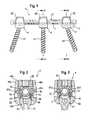
- FIG. 1shows a side view of the stabilization device according to a first embodiment.
- FIG. 2shows an enlarged sectional view along line A-A in FIG. 1 .
- FIG. 3shows an enlarged sectional view along line B-B in FIG. 1 .
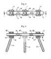
- FIG. 4shows a top view of the stabilization device of FIG. 1 .
- FIG. 5shows a sectional view of the stabilization device of FIG. 4 along line C-C.
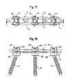
- FIG. 6shows a side view of the stabilization device according to a second embodiment.
- FIG. 7shows an enlarged sectional view along line A-A of FIG. 6 .
- FIG. 8shows an enlarged sectional view along line B-B of FIG. 6 .
- FIG. 9shows a top view of the stabilization device of FIG. 6 .
- FIG. 10shows a sectional view along C-C of FIG. 9 .
- FIG. 11shows a third embodiment of the stabilization device in a top view.
- FIG. 12shows a side view of the stabilization device of FIG. 11 .
- FIG. 13shows a fourth embodiment of the stabilization device in a sectional view along the rod axis.
- FIG. 14shows an enlarged sectional view along line B-B of FIG. 13 .
- FIG. 15shows a top view of the stabilization device of FIG. 13 .
- FIG. 16shows a side view of the stabilization device of FIG. 15 .
- FIG. 17shows a fifth embodiment of the stabilization device in a side view.
- FIG. 18shows an enlarged sectional view along line B-B of FIG. 17 .
- FIG. 19shows a top view of the fifth embodiment of the stabilization device.
- FIG. 20shows a sectional view of the stabilization device of FIG. 19 along line A-A.
- the bone stabilization device 1includes a flexible rod 2 and at least one laterally arranged connection rod 3 which are both connected to bone anchoring elements 4 , 4 ′.
- the flexible rod 2includes at least a portion 2 a exhibiting flexibility under the action of compression and extension forces acting along the rod axis and under the action of torsional, shearing and/or bending forces.
- the flexible rod 2is made of a hollow tube of a rigid material, such as a body compatible metal, metal alloy, in particular of titanium, Nitinol, stainless steel or of a rigid body compatible plastic material such as PEEK or carbon fiber reinforced PEEK.
- the length of the flexible rodis such that it spans at least the distance between two adjacent vertebrae. In the embodiment shown, the flexible rod spans the distance between three adjacent vertebrae.
- the flexible portion 2 ais provided between rigid portions 2 b .
- the rigid portions 2 bare connected to the bone anchoring elements.
- the flexibility of the flexible portionis achieved by a helix-shaped recess in the wall of the hollow tube. However, any other design conferring flexibility to the rod is possible.
- connection rod 3is arranged the diameter of which is smaller than that of the flexible rod 2 .
- the length of each of the connection rods 3can be the same as that of the flexible rod 2 or can be smaller than that of the flexible rod 2 .
- the connection rods 3are not fully straight, but have a first straight section 3 a , a step portion 3 b and a second straight section 3 c .
- the connection rods 3are preferably less flexible when compared to the flexible section 2 a of the flexible rod 2 .
- the connection rods 3are made of a body compatible metal such as stainless steel, titanium, titanium alloys such as Nitinol or a rigid plastic material such as PEEK or carbon reinforced PEEK.
- the diameter of the connections rods 3is considerably smaller than that of the flexible stabilization rod 2 .
- the diameter of the connections rods 3has to have such a size that the connection rods 3 are rigid enough to resist bending forces.
- the two lateral connection rods 3are connected to each other at one of their respective ends by means of a bracket 5 which is formed such that it is orientated downwards or upwards in order to circumvent the flexible rod 2 .
- the bracket 5can be integrally formed with the rods 3 or can be a separate part which is connectable to the rods 3 .
- the bone anchoring element 4is designed in the form of a polyaxial bone screw. It includes a screw element having a threaded shank 41 and spherically shaped head 42 and a receiving part 43 for receiving the flexible rod 2 and the connection rods 3 .
- the receiving part 43has a substantially cylindrical or cuboid shape with a first end 43 a and an opposite second end 43 b and a coaxial bore 44 extending from the first end 43 a in the direction of the second end 43 b and tapering towards the second end such that a seat is provided for the head 42 of the screw element which is pivotably held in the receiving part.
- the receiving part 43includes a substantially U-shaped recess 45 extending from the first end 43 a in the direction of the second end 43 b .
- two free legs 46 a , 46 bare formed which form together with the bottom of the recess a channel for accommodating the flexible rod 2 .
- bores 47 a , 47 bare provided and which form guides for the connection rods.
- the bores 47 a , 47 bextend through the free legs 46 a , 46 so that the connection rods 3 can be guided through the bores from one side of the receiving part and exit through the other side.
- the size of the boresis such that the diameter is slightly larger than the outer diameter of the connection rods 3 to allow a sliding movement of the connection rods 3 within the bores 47 a , 47 b.
- the bores 47 a , 47 bare located fully within the free legs 46 a and 46 b and form through holes.
- the location of the through holes 47 a , 47 bis such that the bore axis is in one plane with the axis of the flexible rod 2 when the flexible rod 2 is inserted.
- the polyaxial bone screwfurther includes a pressure element 48 which is substantially cylindrical so as to be movable in the bore 44 and which has on its side facing the head 42 a spherical recess 49 to encompass a portion of the head to distribute the pressure onto the head 42 . It further includes a coaxial bore 50 to allow access to the head 42 .
- the pressure element 48On its side opposite to the spherical recess the pressure element 48 has a cylinder segment-shaped recess 51 which is sized such that the flexible rod 2 can be inserted and guided therein. In the embodiment shown in FIGS. 2 and 3 the cylinder segment-shaped recess 51 is sized such that the flexible rod projects above the pressure element.
- the bone anchoring elementfurther includes a fixation screw 52 which engages with an inner thread of the free legs 46 a , 46 b .
- the fixation screw 52serves for pressing onto the flexible rod 2 in the receiving part and therefore indirectly pressing onto the pressure element 48 for exerting pressure onto the head 42 to lock the angular position of the screw element with respect to the receiving part.
- FIG. 3shows a bone anchoring element 4 ′ which is a modification of the bone anchoring element which is suitable for accommodating the portion 3 c of the connection rods shown in FIG. 4 . It differs from the bone anchoring element according to FIG. 2 in the construction of the bores 47 a ′, 47 W. All other elements of the bone anchoring element are the same as those of the bone anchoring element of FIG. 2 and the description thereof will not be repeated.
- the bores 47 a ′, 47 b ′have a semi-circular cross section. The bores are open to the channel which accommodates the flexible rod 2 .
- the connection rods 3are secured from inside the receiving part by the flexible rod 2 against falling out from the bores 47 a ′, 47 b ′.
- connection rods 3it is possible to arrange the connection rods 3 more closely to the flexible rod 2 and the connection rods can be put in place through the U-shaped channel. As particularly shown in FIGS. 1 and 4 , with this construction it is possible to span several motion segments of the spinal column with different distances of the flexible rod 2 and the connection rods 3 from each other.
- connection rods 3can be connected with each other with a integrally formed bracket 5
- the connection rodscan be mechanically connected at one or at both ends with a connection which is applied after the rods have been introduced into the receiving parts. They must not necessarily be connected, but can be single rods. To avoid that the single rods escape from the receiving parts in the course of their sliding movement, one end of the rods 3 can have a larger diameter which prevents sliding through the guides.
- connection rodsare shown as cylindrical rods, the cross section of the connection rods may be non-circular, for example oval-shaped, polygon-shaped or otherwise shaped.
- connection rodscan be straight.
- connection rodsare secured within the bores 47 a , 47 b against escaping.
- a stabilizing devicewithout the flexible rod.
- the bracket 5 shown in FIG. 1not only serves for connection of the connection rods 3 but also forms a stop for the sliding movement of the connection rods 3 . It is also possible to provide a stop at the opposite end at a distance from the anchoring element 4 so that the connection rods 3 are still fully movable.
- the guides and/or the connection rodscan be provided with materials and/or devices for facilitating sliding of the connection rods 3 .
- Such materials and/or devicescan be, for example, coating, sliding guides or sliding bearings.
- FIGS. 6 to 10show a second embodiment of the stabilization device which differs from the first embodiment shown in FIGS. 1 to 5 only by the pressure element 480 compared to the pressure element 48 .
- the pressure element 480which allows to omit the flexible rod 2 and to provide stabilization only via the connection rods 3 . All other elements and parts are identical to the first embodiment and the description thereof will not be repeated.
- the pressure element 480has instead of the cylinder segment-shaped recess 51 a cylindrical portion 481 which extends coaxially to the main portion of the pressure element and has a diameter which is smaller than the main portion.
- the length of the cylindrical portion 481is such that the pressure element extends up to the fixation screw 52 so that the fixation screw 52 can press the pressure element 480 downwards when it is tightened.
- This embodimentis particularly suitable for applications where a flexible rod is not necessary. If the stabilization device is used without a flexible rod a shown in FIGS. 6 to 10 , the pressure element 480 can be used instead of the pressure element 48 while all other parts of the first embodiment remaining the same. Hence, the construction of the bone anchoring element with respect to the bores 47 a , 47 b or 47 a ′, 47 b ′ remains the same.
- FIGS. 11 and 12show a third embodiment of the stabilization device which differs from the second embodiment according to FIGS. 6 to 10 only in that the bracket 5 connecting the rods 3 is omitted. In such a case, it is advantageous to provide stops at both ends of the connection rods to allow a free but limited movement of the connecting rods in the receiving parts.
- FIGS. 13 to 16show a fourth embodiment of the stabilization device.
- a flexible rod 2 and fully straight connection rods 3are used which are connected by the bracket 5 .
- the assembly of the connection rods 3can be introduced in the receiving parts simultaneously by gripping the bracket.
- the bone anchoring element 400 of the fourth embodimentdiffers from the bone anchoring element 4 described in connection with the first embodiment by the location and design of the guides for guiding the connection rods 3 .
- the free legs 46 a , 46 bhave recesses 470 a , 470 b which are at the outer surface and are open to the outside of the receiving part.
- the cross section of the recesses 470 a , 470 bis substantially U-shaped and the size is such that the connection rods 3 can slide therein.
- the free legs 46 a , 46 bhave a support structure 471 supporting a closure element 472 , for example a closure bar, which closes the recess 470 a , 470 b respectively.
- the recesses 470 a , 470 bare located at the same height as the bores 47 a , 47 b of the first embodiment.
- bone anchoring element 400All other portions of the bone anchoring element 400 are identical to those of the first embodiment. It shall be noted that the bone anchoring element 400 can also be provided with a pressure element 480 described before when the use of a flexible rod 2 is not necessary.
- the stabilization device of a fifth embodiment according to FIGS. 17 to 20has instead of the flexible rod 2 which is a hollow tube with a flexible section, a flexible rod 20 which is made of a flexible plastic material such as an elastomer, for example polyurethane, polycarbonateurethane (PCU) or polysiloxane.
- the flexible rod 20exhibits axial flexibility under the action of axial extension or compression.
- the bone anchoring element 401is adapted to clamp the flexible rod 20 as can be seen in FIG. 18 .
- the bone anchoring element 401includes bores 47 a , 47 b in the wall of the legs as described with respect to the first embodiment and differs from the bone anchoring element of the first embodiment by the shape of the pressure element 402 and the fixation element 404 .
- the pressure element 402extends above the surface of the flexible rod 20 when the flexible rod 20 is inserted.
- projections 403are formed which engage in the surface of the flexible rod 20 .
- the fixation element 404is a fixation screw as in the first embodiment. However, it has a projection 405 on its lower side facing the flexible rod 20 which engages in the surface structure of the flexible rod 20 .
- connection rods 3can be varied between the embodiments described.
- specific designs of polyaxial bone screwsare described, other designs can also be used, for example polyaxial screws with two part locking elements, polyaxial screws wherein the screw element is loaded into the receiving part from the top or from the bottom, polyaxial screws with various shapes of pressure elements to lock the angular position of the screw element with respect to the receiving part.
- connection rodsare inserted into the guides of the polyaxial bone anchoring elements for aligning the receiving parts with respect to each other in an axial direction.
- the connection rodscan be clipped into the recesses by inserting them in the U-shaped channel. This facilitates the step of connecting the bone anchoring elements.
- the flexible rodis inserted. After insertion of the flexible rod the position and the distance of the bone anchoring elements from each other is adjusted. Finally the flexible rod is fixed by tightening the fixation element.
- the flexible rodcan first be inserted into the U-shaped channels of the bone anchoring elements before guiding the connection rods through the respective guides.
- connection rods 3can slide within the guides.
- the connection rodsprovide resistance against torsional and/or shearing and/or bending forces acting on the stabilization device.
Landscapes
- Health & Medical Sciences (AREA)
- Orthopedic Medicine & Surgery (AREA)
- Life Sciences & Earth Sciences (AREA)
- Surgery (AREA)
- Neurology (AREA)
- Engineering & Computer Science (AREA)
- Biomedical Technology (AREA)
- Animal Behavior & Ethology (AREA)
- Public Health (AREA)
- Veterinary Medicine (AREA)
- Heart & Thoracic Surgery (AREA)
- General Health & Medical Sciences (AREA)
- Nuclear Medicine, Radiotherapy & Molecular Imaging (AREA)
- Molecular Biology (AREA)
- Medical Informatics (AREA)
- Cardiology (AREA)
- Oral & Maxillofacial Surgery (AREA)
- Transplantation (AREA)
- Vascular Medicine (AREA)
- Surgical Instruments (AREA)
- Prostheses (AREA)
Abstract
Description
Claims (36)
Priority Applications (2)
| Application Number | Priority Date | Filing Date | Title |
|---|---|---|---|
| US12/550,654US9101403B2 (en) | 2008-09-05 | 2009-08-31 | Bone anchoring element and stabilization device for bones, in particular for the spinal column |
| US14/798,072US9907578B2 (en) | 2008-09-05 | 2015-07-13 | Bone anchoring element and stabilization device for bones, in particular for the spinal column |
Applications Claiming Priority (5)
| Application Number | Priority Date | Filing Date | Title |
|---|---|---|---|
| US9466408P | 2008-09-05 | 2008-09-05 | |
| EP08015721.7 | 2008-09-05 | ||
| EP08015721AEP2160989B1 (en) | 2008-09-05 | 2008-09-05 | Stabilization device for bones, in particular for the spinal column |
| EP08015721 | 2008-09-05 | ||
| US12/550,654US9101403B2 (en) | 2008-09-05 | 2009-08-31 | Bone anchoring element and stabilization device for bones, in particular for the spinal column |
Related Child Applications (1)
| Application Number | Title | Priority Date | Filing Date |
|---|---|---|---|
| US14/798,072ContinuationUS9907578B2 (en) | 2008-09-05 | 2015-07-13 | Bone anchoring element and stabilization device for bones, in particular for the spinal column |
Publications (2)
| Publication Number | Publication Date |
|---|---|
| US20100094348A1 US20100094348A1 (en) | 2010-04-15 |
| US9101403B2true US9101403B2 (en) | 2015-08-11 |
Family
ID=39952184
Family Applications (2)
| Application Number | Title | Priority Date | Filing Date |
|---|---|---|---|
| US12/550,654Active2032-03-30US9101403B2 (en) | 2008-09-05 | 2009-08-31 | Bone anchoring element and stabilization device for bones, in particular for the spinal column |
| US14/798,072ActiveUS9907578B2 (en) | 2008-09-05 | 2015-07-13 | Bone anchoring element and stabilization device for bones, in particular for the spinal column |
Family Applications After (1)
| Application Number | Title | Priority Date | Filing Date |
|---|---|---|---|
| US14/798,072ActiveUS9907578B2 (en) | 2008-09-05 | 2015-07-13 | Bone anchoring element and stabilization device for bones, in particular for the spinal column |
Country Status (7)
| Country | Link |
|---|---|
| US (2) | US9101403B2 (en) |
| EP (2) | EP2484300B1 (en) |
| JP (1) | JP5538780B2 (en) |
| KR (1) | KR101563262B1 (en) |
| CN (1) | CN101664335B (en) |
| ES (2) | ES2387512T3 (en) |
| TW (1) | TWI480018B (en) |
Cited By (2)
| Publication number | Priority date | Publication date | Assignee | Title |
|---|---|---|---|---|
| US20150359568A1 (en)* | 2014-06-13 | 2015-12-17 | Warsaw Orthopedic, Inc. | Bone fastener and methods of use |
| US20190125414A1 (en)* | 2009-09-09 | 2019-05-02 | Globus Medical, Inc. | Spine surgery device and method |
Families Citing this family (62)
| Publication number | Priority date | Publication date | Assignee | Title |
|---|---|---|---|---|
| US7833250B2 (en) | 2004-11-10 | 2010-11-16 | Jackson Roger P | Polyaxial bone screw with helically wound capture connection |
| US8353932B2 (en) | 2005-09-30 | 2013-01-15 | Jackson Roger P | Polyaxial bone anchor assembly with one-piece closure, pressure insert and plastic elongate member |
| US10729469B2 (en) | 2006-01-09 | 2020-08-04 | Roger P. Jackson | Flexible spinal stabilization assembly with spacer having off-axis core member |
| US10258382B2 (en) | 2007-01-18 | 2019-04-16 | Roger P. Jackson | Rod-cord dynamic connection assemblies with slidable bone anchor attachment members along the cord |
| US7862587B2 (en) | 2004-02-27 | 2011-01-04 | Jackson Roger P | Dynamic stabilization assemblies, tool set and method |
| US8292926B2 (en) | 2005-09-30 | 2012-10-23 | Jackson Roger P | Dynamic stabilization connecting member with elastic core and outer sleeve |
| US8876868B2 (en) | 2002-09-06 | 2014-11-04 | Roger P. Jackson | Helical guide and advancement flange with radially loaded lip |
| US7621918B2 (en) | 2004-11-23 | 2009-11-24 | Jackson Roger P | Spinal fixation tool set and method |
| US7377923B2 (en) | 2003-05-22 | 2008-05-27 | Alphatec Spine, Inc. | Variable angle spinal screw assembly |
| US7766915B2 (en) | 2004-02-27 | 2010-08-03 | Jackson Roger P | Dynamic fixation assemblies with inner core and outer coil-like member |
| US8926670B2 (en) | 2003-06-18 | 2015-01-06 | Roger P. Jackson | Polyaxial bone screw assembly |
| US7776067B2 (en) | 2005-05-27 | 2010-08-17 | Jackson Roger P | Polyaxial bone screw with shank articulation pressure insert and method |
| US7179261B2 (en) | 2003-12-16 | 2007-02-20 | Depuy Spine, Inc. | Percutaneous access devices and bone anchor assemblies |
| US11419642B2 (en) | 2003-12-16 | 2022-08-23 | Medos International Sarl | Percutaneous access devices and bone anchor assemblies |
| US7527638B2 (en) | 2003-12-16 | 2009-05-05 | Depuy Spine, Inc. | Methods and devices for minimally invasive spinal fixation element placement |
| US11241261B2 (en) | 2005-09-30 | 2022-02-08 | Roger P Jackson | Apparatus and method for soft spinal stabilization using a tensionable cord and releasable end structure |
| JP2007525274A (en) | 2004-02-27 | 2007-09-06 | ロジャー・ピー・ジャクソン | Orthopedic implant rod reduction instrument set and method |
| US8152810B2 (en) | 2004-11-23 | 2012-04-10 | Jackson Roger P | Spinal fixation tool set and method |
| US7160300B2 (en) | 2004-02-27 | 2007-01-09 | Jackson Roger P | Orthopedic implant rod reduction tool set and method |
| US7651502B2 (en) | 2004-09-24 | 2010-01-26 | Jackson Roger P | Spinal fixation tool set and method for rod reduction and fastener insertion |
| US8926672B2 (en) | 2004-11-10 | 2015-01-06 | Roger P. Jackson | Splay control closure for open bone anchor |
| US9168069B2 (en) | 2009-06-15 | 2015-10-27 | Roger P. Jackson | Polyaxial bone anchor with pop-on shank and winged insert with lower skirt for engaging a friction fit retainer |
| US20120029568A1 (en)* | 2006-01-09 | 2012-02-02 | Jackson Roger P | Spinal connecting members with radiused rigid sleeves and tensioned cords |
| US9980753B2 (en) | 2009-06-15 | 2018-05-29 | Roger P Jackson | pivotal anchor with snap-in-place insert having rotation blocking extensions |
| WO2006057837A1 (en) | 2004-11-23 | 2006-06-01 | Jackson Roger P | Spinal fixation tool attachment structure |
| US9216041B2 (en) | 2009-06-15 | 2015-12-22 | Roger P. Jackson | Spinal connecting members with tensioned cords and rigid sleeves for engaging compression inserts |
| US8444681B2 (en) | 2009-06-15 | 2013-05-21 | Roger P. Jackson | Polyaxial bone anchor with pop-on shank, friction fit retainer and winged insert |
| US8308782B2 (en) | 2004-11-23 | 2012-11-13 | Jackson Roger P | Bone anchors with longitudinal connecting member engaging inserts and closures for fixation and optional angulation |
| US7901437B2 (en) | 2007-01-26 | 2011-03-08 | Jackson Roger P | Dynamic stabilization member with molded connection |
| US8105368B2 (en) | 2005-09-30 | 2012-01-31 | Jackson Roger P | Dynamic stabilization connecting member with slitted core and outer sleeve |
| CA2670988C (en) | 2006-12-08 | 2014-03-25 | Roger P. Jackson | Tool system for dynamic spinal implants |
| US8475498B2 (en) | 2007-01-18 | 2013-07-02 | Roger P. Jackson | Dynamic stabilization connecting member with cord connection |
| US8366745B2 (en) | 2007-05-01 | 2013-02-05 | Jackson Roger P | Dynamic stabilization assembly having pre-compressed spacers with differential displacements |
| US10792074B2 (en) | 2007-01-22 | 2020-10-06 | Roger P. Jackson | Pivotal bone anchor assemly with twist-in-place friction fit insert |
| US8979904B2 (en) | 2007-05-01 | 2015-03-17 | Roger P Jackson | Connecting member with tensioned cord, low profile rigid sleeve and spacer with torsion control |
| US10383660B2 (en) | 2007-05-01 | 2019-08-20 | Roger P. Jackson | Soft stabilization assemblies with pretensioned cords |
| AU2010260521C1 (en) | 2008-08-01 | 2013-08-01 | Roger P. Jackson | Longitudinal connecting member with sleeved tensioned cords |
| EP2484300B1 (en)* | 2008-09-05 | 2015-05-20 | Biedermann Technologies GmbH & Co. KG | Stabilization device for bones, in particular for the spinal column |
| CN103826560A (en) | 2009-06-15 | 2014-05-28 | 罗杰.P.杰克逊 | Polyaxial Bone Anchor with Socket Stem and Winged Inserts with Friction Fit Compression Collars |
| US11229457B2 (en) | 2009-06-15 | 2022-01-25 | Roger P. Jackson | Pivotal bone anchor assembly with insert tool deployment |
| US9668771B2 (en) | 2009-06-15 | 2017-06-06 | Roger P Jackson | Soft stabilization assemblies with off-set connector |
| US8998959B2 (en) | 2009-06-15 | 2015-04-07 | Roger P Jackson | Polyaxial bone anchors with pop-on shank, fully constrained friction fit retainer and lock and release insert |
| EP2485654B1 (en) | 2009-10-05 | 2021-05-05 | Jackson P. Roger | Polyaxial bone anchor with non-pivotable retainer and pop-on shank, some with friction fit |
| US8740945B2 (en)* | 2010-04-07 | 2014-06-03 | Zimmer Spine, Inc. | Dynamic stabilization system using polyaxial screws |
| US12383311B2 (en) | 2010-05-14 | 2025-08-12 | Roger P. Jackson | Pivotal bone anchor assembly and method for use thereof |
| US8377139B2 (en) | 2010-06-17 | 2013-02-19 | Aesculap Implant Systems, Llc | Standalone interbody fusion device with locking and release mechanism |
| US8920471B2 (en) | 2010-07-12 | 2014-12-30 | K2M, Inc. | Transverse connector |
| AU2011299558A1 (en) | 2010-09-08 | 2013-05-02 | Roger P. Jackson | Dynamic stabilization members with elastic and inelastic sections |
| AU2011324058A1 (en) | 2010-11-02 | 2013-06-20 | Roger P. Jackson | Polyaxial bone anchor with pop-on shank and pivotable retainer |
| EP2460484A1 (en)* | 2010-12-01 | 2012-06-06 | FACET-LINK Inc. | Variable angle bone screw fixation assembly |
| JP5865479B2 (en) | 2011-03-24 | 2016-02-17 | ロジャー・ピー・ジャクソン | Multiaxial bone anchor with compound joint and pop-mounted shank |
| US8911479B2 (en) | 2012-01-10 | 2014-12-16 | Roger P. Jackson | Multi-start closures for open implants |
| US8911478B2 (en) | 2012-11-21 | 2014-12-16 | Roger P. Jackson | Splay control closure for open bone anchor |
| US10058354B2 (en) | 2013-01-28 | 2018-08-28 | Roger P. Jackson | Pivotal bone anchor assembly with frictional shank head seating surfaces |
| US8852239B2 (en) | 2013-02-15 | 2014-10-07 | Roger P Jackson | Sagittal angle screw with integral shank and receiver |
| US9566092B2 (en) | 2013-10-29 | 2017-02-14 | Roger P. Jackson | Cervical bone anchor with collet retainer and outer locking sleeve |
| US9717533B2 (en) | 2013-12-12 | 2017-08-01 | Roger P. Jackson | Bone anchor closure pivot-splay control flange form guide and advancement structure |
| US9451993B2 (en) | 2014-01-09 | 2016-09-27 | Roger P. Jackson | Bi-radial pop-on cervical bone anchor |
| US10064658B2 (en) | 2014-06-04 | 2018-09-04 | Roger P. Jackson | Polyaxial bone anchor with insert guides |
| US9597119B2 (en) | 2014-06-04 | 2017-03-21 | Roger P. Jackson | Polyaxial bone anchor with polymer sleeve |
| TWI559909B (en)* | 2016-01-25 | 2016-12-01 | Univ Nat Cheng Kung | Artificial cage with adjustable height |
| RU203215U9 (en)* | 2020-10-08 | 2021-05-31 | Российская Федерация, от имени которой выступает Министерство здравоохранения Российской Федерации (Минздрав России) | Corrective device for the surgical treatment of congenital kyphoscoliosis of the thoracic and lumbar spine against the background of impaired formation of the vertebrae in children under three years of age |
Citations (41)
| Publication number | Priority date | Publication date | Assignee | Title |
|---|---|---|---|---|
| US4697582A (en) | 1983-10-28 | 1987-10-06 | Peze William | Appliance for correcting rachidial deformities |
| US5611801A (en)* | 1994-11-29 | 1997-03-18 | Pioneer Laboratories, Inc. | Method and apparatus for bone fracture fixation |
| US5702395A (en)* | 1992-11-10 | 1997-12-30 | Sofamor S.N.C. | Spine osteosynthesis instrumentation for an anterior approach |
| US5800435A (en)* | 1996-10-09 | 1998-09-01 | Techsys, Llc | Modular spinal plate for use with modular polyaxial locking pedicle screws |
| US5863293A (en)* | 1996-10-18 | 1999-01-26 | Spinal Innovations | Spinal implant fixation assembly |
| US6086590A (en)* | 1999-02-02 | 2000-07-11 | Pioneer Laboratories, Inc. | Cable connector for orthopaedic rod |
| US20020055740A1 (en)* | 2000-11-08 | 2002-05-09 | The Cleveland Clinic Foundation | Method and apparatus for correcting spinal deformity |
| DE10117426A1 (en) | 2001-04-06 | 2002-10-10 | Michael Hahn | Fixator and method for fixing a section of a spine |
| WO2003034930A1 (en) | 2001-10-23 | 2003-05-01 | Biedermann Motech Gmbh | Bone fixation device and screw therefor |
| US20030144664A1 (en) | 1999-12-24 | 2003-07-31 | Remi Cavagna | Pedicle screws with inclined channels to hold support rods |
| US6645207B2 (en)* | 2000-05-08 | 2003-11-11 | Robert A. Dixon | Method and apparatus for dynamized spinal stabilization |
| US6706044B2 (en)* | 2001-04-19 | 2004-03-16 | Spineology, Inc. | Stacked intermedular rods for spinal fixation |
| US20040111088A1 (en) | 2002-12-06 | 2004-06-10 | Picetti George D. | Multi-rod bone attachment member |
| US20040181224A1 (en)* | 2003-03-11 | 2004-09-16 | Biedermann Motech Gmbh | Anchoring element for use in spine or bone surgery, methods for use and production thereof |
| WO2004105577A2 (en) | 2003-05-23 | 2004-12-09 | Globus Medical, Inc. | Spine stabilization system |
| US20040249378A1 (en)* | 2001-10-04 | 2004-12-09 | Saint Martin Pierre Henri | Spinal osteosynthesis assembly comprising the head of an anchoring member and a tool for fixing said head |
| US20050085815A1 (en) | 2003-10-17 | 2005-04-21 | Biedermann Motech Gmbh | Rod-shaped implant element for application in spine surgery or trauma surgery, stabilization apparatus comprising said rod-shaped implant element, and production method for the rod-shaped implant element |
| US20050171537A1 (en) | 2001-11-27 | 2005-08-04 | Christian Mazel | Connector for vertebral anchoring system |
| US20050228378A1 (en)* | 2004-03-31 | 2005-10-13 | Iain Kalfas | Spinal rod connector |
| US20060089644A1 (en)* | 2004-10-27 | 2006-04-27 | Felix Brent A | Spinal stabilizing system |
| US20060142758A1 (en) | 2002-09-11 | 2006-06-29 | Dominique Petit | Linking element for dynamically stabilizing a spinal fixing system and spinal fixing system comprising same |
| WO2006066685A1 (en) | 2004-12-17 | 2006-06-29 | Zimmer Gmbh | Intervertebral stabilisation system |
| US20070049937A1 (en) | 2005-08-24 | 2007-03-01 | Wilfried Matthis | Rod-shaped implant element for the application in spine surgery or trauma surgery and stabilization device with such a rod-shaped implant element |
| WO2007038429A1 (en) | 2005-09-27 | 2007-04-05 | Endius, Inc. | Methods and apparatuses for stabilizing the spine through an access device |
| WO2007060534A2 (en) | 2005-11-24 | 2007-05-31 | Giuseppe Calvosa | Modular vertebral stabilizer |
| EP1795134A1 (en) | 2005-11-17 | 2007-06-13 | BIEDERMANN MOTECH GmbH | Polyaxial screw for flexible rod |
| EP1810624A1 (en) | 2006-01-24 | 2007-07-25 | BIEDERMANN MOTECH GmbH | Connecting rod with external adjustment element |
| US20070225708A1 (en)* | 2005-12-23 | 2007-09-27 | Lutz Biedermann | Dynamic stabilization device for bones or vertebrae |
| US20070233073A1 (en) | 2006-03-02 | 2007-10-04 | Sdgi Holdings, Inc. | Spinal rod characterized by a time-varying stiffness |
| US20070288008A1 (en)* | 2004-09-22 | 2007-12-13 | Kyung-Woo Park | Semi-rigid spinal fixation apparatus |
| EP1891904A1 (en) | 2006-08-24 | 2008-02-27 | BIEDERMANN MOTECH GmbH | Bone anchoring device |
| US20080058818A1 (en)* | 2006-09-05 | 2008-03-06 | Schwab Frank J | Vertebral Anchor |
| EP1923011A1 (en) | 2006-11-17 | 2008-05-21 | BIEDERMANN MOTECH GmbH | Bone anchoring device |
| US20080177328A1 (en)* | 2006-12-28 | 2008-07-24 | Mi4Spine, Llc | Method for Vertebral Disc Annular Fibrosis Tensioning and Lengthening |
| US20080177335A1 (en)* | 2006-10-26 | 2008-07-24 | Warsaw Orthopedic Inc. | Bone screw |
| US20080262551A1 (en)* | 2007-04-19 | 2008-10-23 | Zimmer Spine, Inc. | Method and associated instrumentation for installation of spinal dynamic stabilization system |
| US20080262553A1 (en)* | 2007-04-18 | 2008-10-23 | Ebi, Llc | Spinal connector |
| US20080269810A1 (en)* | 2007-04-12 | 2008-10-30 | Texas Scottish Rite Hospital For Children | Orthopedic Fastener for Stabilization and Fixation |
| US20090131982A1 (en)* | 2007-11-16 | 2009-05-21 | Frank Johann Schwab | Bone anchor and spinal alignment system |
| US7588588B2 (en)* | 2003-10-21 | 2009-09-15 | Innovative Spinal Technologies | System and method for stabilizing of internal structures |
| US20100087865A1 (en)* | 2008-10-08 | 2010-04-08 | Lutz Biedermann | Bone anchoring device and stabilization device for bone parts or vertebrae comprising such a bone anchoring device |
Family Cites Families (202)
| Publication number | Priority date | Publication date | Assignee | Title |
|---|---|---|---|---|
| NL7306853A (en)* | 1973-05-16 | 1974-11-19 | ||
| GB1519139A (en)* | 1974-06-18 | 1978-07-26 | Crock H V And Pericic L | L securing elongate members to structurs more especially in surgical procedures |
| US4653481A (en)* | 1985-07-24 | 1987-03-31 | Howland Robert S | Advanced spine fixation system and method |
| US4805602A (en)* | 1986-11-03 | 1989-02-21 | Danninger Medical Technology | Transpedicular screw and rod system |
| FR2657774B1 (en)* | 1990-02-08 | 1992-05-22 | Sofamor | SACRED TAKING SHOE FOR A SPINAL OSTEOSYNTHESIS DEVICE. |
| FR2658413B1 (en)* | 1990-02-19 | 1997-01-03 | Sofamor | OSTEOSYNTHESIS DEVICE FOR THE CORRECTION OF SPINAL DEVIATIONS. |
| CH683024A5 (en)* | 1991-04-16 | 1993-12-31 | Synthes Ag | Connecting means for connecting a first adjustable with a second construction element, in particular of tubes or rods of a fixation device. |
| US5152303A (en)* | 1991-06-18 | 1992-10-06 | Carl Allen | Anterolateral spinal fixation system and related insertion process |
| US5261911A (en)* | 1991-06-18 | 1993-11-16 | Allen Carl | Anterolateral spinal fixation system |
| FR2681776A1 (en)* | 1991-09-30 | 1993-04-02 | Fixano Sa | VERTEBRAL OSTEOSYNTHESIS DEVICE. |
| NL9200288A (en)* | 1992-02-17 | 1993-09-16 | Acromed Bv | DEVICE FOR FIXING AT LEAST A PART OF THE CERVICAL AND / OR THORACAL SPIRIT COLUMN. |
| US5810817A (en)* | 1992-06-19 | 1998-09-22 | Roussouly; Pierre | Spinal therapy apparatus |
| US5387212A (en)* | 1993-01-26 | 1995-02-07 | Yuan; Hansen A. | Vertebral locking and retrieving system with central locking rod |
| US5330473A (en)* | 1993-03-04 | 1994-07-19 | Advanced Spine Fixation Systems, Inc. | Branch connector for spinal fixation systems |
| US5470333A (en)* | 1993-03-11 | 1995-11-28 | Danek Medical, Inc. | System for stabilizing the cervical and the lumbar region of the spine |
| FR2704134B1 (en)* | 1993-04-20 | 1998-08-28 | Stryker Corp | Assembly piece for osteosynthesis device. |
| US5437669A (en)* | 1993-08-12 | 1995-08-01 | Amei Technologies Inc. | Spinal fixation systems with bifurcated connectors |
| US5466238A (en)* | 1993-08-27 | 1995-11-14 | Lin; Chih-I | Vertebral locking and retrieving system having a fixation crossbar |
| US5454812A (en)* | 1993-11-12 | 1995-10-03 | Lin; Chih-I | Spinal clamping device having multiple distance adjusting strands |
| US5499983A (en)* | 1994-02-23 | 1996-03-19 | Smith & Nephew Richards, Inc. | Variable angle spinal screw |
| US5601552A (en)* | 1994-03-18 | 1997-02-11 | Sofamor, S.N.C. | Fixing device for a rigid transverse connection device between rods of a spinal osteosynthesis system |
| US5507746A (en)* | 1994-07-27 | 1996-04-16 | Lin; Chih-I | Holding and fixing mechanism for orthopedic surgery |
| US6176861B1 (en)* | 1994-10-25 | 2001-01-23 | Sdgi Holdings, Inc. | Modular spinal system |
| US5474551A (en)* | 1994-11-18 | 1995-12-12 | Smith & Nephew Richards, Inc. | Universal coupler for spinal fixation |
| US20040049197A1 (en)* | 1994-12-08 | 2004-03-11 | Jose Vicente Barbera Alacreu | Dorsolumbar and lumbosacral vertebral fixation system |
| US5620443A (en)* | 1995-01-25 | 1997-04-15 | Danek Medical, Inc. | Anterior screw-rod connector |
| CA2237811C (en)* | 1995-11-30 | 2003-09-02 | Synthes (U.S.A.) | Bone-fixing device |
| FR2742040B1 (en)* | 1995-12-07 | 1998-01-23 | Groupe Lepine | ASSEMBLY DEVICE FOR EXTENDED PARTS OF OSTEOSYNTHESIS MATERIAL, ESPECIALLY SPINAL |
| FR2743712B1 (en)* | 1996-01-19 | 1998-04-30 | Louis Rene | POSTERIOR VERTEBRAL OSTEOSYNTHESIS ANCHORING DEVICE |
| US5746741A (en)* | 1996-05-06 | 1998-05-05 | Tufts University | External fixator system |
| US5728098A (en)* | 1996-11-07 | 1998-03-17 | Sdgi Holdings, Inc. | Multi-angle bone screw assembly using shape-memory technology |
| US5964769A (en)* | 1997-08-26 | 1999-10-12 | Spinal Concepts, Inc. | Surgical cable system and method |
| FR2771918B1 (en)* | 1997-12-09 | 2000-04-21 | Dimso Sa | CONNECTOR FOR SPINAL OSTEOSYNTHESIS DEVICE |
| FR2784282B1 (en)* | 1998-10-09 | 2001-03-23 | Dimso Sa | SPINAL OSTEOSYNTHESIS SYSTEM WITH IMPROVED RIGIDITY |
| CA2330705A1 (en)* | 1998-04-29 | 1999-11-04 | Dimso (Distribution Medicale Du Sud-Ouest) | Backbone osteosynthesis system for anterior fixing |
| US6565565B1 (en)* | 1998-06-17 | 2003-05-20 | Howmedica Osteonics Corp. | Device for securing spinal rods |
| DE19848715C1 (en)* | 1998-10-22 | 2000-08-24 | Aesculap Ag & Co Kg | Osteo-synthetic holding system has locking units for the holding rods of different dimensions for the holding rods to allow adjustments to the setting of the bones or fragments before final clamping |
| US6146386A (en)* | 1999-02-04 | 2000-11-14 | Sdgi Holdings, Inc. | Cable operated bone anchor compressor |
| US6136002A (en)* | 1999-02-05 | 2000-10-24 | Industrial Technology Research Institute | Anterior spinal fixation system |
| US6315779B1 (en)* | 1999-04-16 | 2001-11-13 | Sdgi Holdings, Inc. | Multi-axial bone anchor system |
| US7122036B2 (en)* | 1999-07-01 | 2006-10-17 | Spinevision, S.A. | Connector for an osteosynthesis system intended to provide a connection between two rods of a spinal osteosynthesis system, osteosynthesis system using such a connector, and method of implanting such an osteosynthesis system |
| US6280442B1 (en)* | 1999-09-01 | 2001-08-28 | Sdgi Holdings, Inc. | Multi-axial bone screw assembly |
| US8187303B2 (en)* | 2004-04-22 | 2012-05-29 | Gmedelaware 2 Llc | Anti-rotation fixation element for spinal prostheses |
| TW411838U (en)* | 1999-12-10 | 2000-11-11 | Ye Jung Chiuan | Fastening hook for spine and reposition device for fastening spine |
| TW447286U (en)* | 1999-12-10 | 2001-07-21 | Lin Jr Yi | Intervertebral restorer |
| FR2804314B1 (en)* | 2000-01-27 | 2003-01-31 | Scientx | INTERVERTEBRAL CONNECTION DEVICE WITH A CONNECTION BAR FOR FIXING A CONNECTING ROD |
| US20020133155A1 (en)* | 2000-02-25 | 2002-09-19 | Ferree Bret A. | Cross-coupled vertebral stabilizers incorporating spinal motion restriction |
| US6471706B1 (en)* | 2000-04-18 | 2002-10-29 | Walter Lorenz Surgical, Inc. | Resorbable bone distractor and method |
| US7651516B2 (en)* | 2000-12-01 | 2010-01-26 | Spinevision S.A. | Connection assembly for the field of spinal osteosynthesis and method for using at least one such assembly |
| US6524311B2 (en)* | 2000-12-01 | 2003-02-25 | Robert W. Gaines, Jr. | Method and apparatus for performing spinal procedures |
| US6726687B2 (en)* | 2000-12-08 | 2004-04-27 | Jackson Roger P | Closure plug for open-headed medical implant |
| EP1219255B1 (en)* | 2000-12-27 | 2003-10-15 | BIEDERMANN MOTECH GmbH | Screw for connection to a rod |
| DE10108965B4 (en)* | 2001-02-17 | 2006-02-23 | DePuy Spine Sàrl | bone screw |
| FR2822053B1 (en)* | 2001-03-15 | 2003-06-20 | Stryker Spine Sa | ANCHORING MEMBER WITH SAFETY RING FOR SPINAL OSTEOSYNTHESIS SYSTEM |
| US6802844B2 (en)* | 2001-03-26 | 2004-10-12 | Nuvasive, Inc | Spinal alignment apparatus and methods |
| DE10115014A1 (en)* | 2001-03-27 | 2002-10-24 | Biedermann Motech Gmbh | anchoring element |
| ATE382298T1 (en)* | 2001-04-24 | 2008-01-15 | Coligne Ag | INSTRUMENTS FOR STABILIZING CERTAIN VERTEBRATES OF THE SPINE |
| US7862587B2 (en)* | 2004-02-27 | 2011-01-04 | Jackson Roger P | Dynamic stabilization assemblies, tool set and method |
| DE10136129A1 (en)* | 2001-07-27 | 2003-02-20 | Biedermann Motech Gmbh | Bone screw and fastening tool for this |
| US6884241B2 (en)* | 2001-09-04 | 2005-04-26 | Orthotec, Llc | Spinal assembly plate |
| US6652526B1 (en)* | 2001-10-05 | 2003-11-25 | Ruben P. Arafiles | Spinal stabilization rod fastener |
| FR2831048B1 (en)* | 2001-10-18 | 2004-09-17 | Ldr Medical | PROGRESSIVE APPROACH OSTEOSYNTHESIS DEVICE AND PRE-ASSEMBLY PROCESS |
| FR2831049B1 (en)* | 2001-10-18 | 2004-08-13 | Ldr Medical | PLATE FOR OSTEOSYNTHESIS DEVICE AND PRE-ASSEMBLY METHOD |
| US6783527B2 (en)* | 2001-10-30 | 2004-08-31 | Sdgi Holdings, Inc. | Flexible spinal stabilization system and method |
| FR2835174B1 (en)* | 2002-01-31 | 2004-03-19 | Materiel Orthopedique En Abreg | CONNECTOR FOR SPINAL OSTEOSYNTHESIS DEVICE, BONE ANCHOR CONNECTOR / MEMBER ASSEMBLY AND SPINAL OSTEOSYNTHESIS DEVICE USING THE SAME |
| FR2835734B1 (en)* | 2002-02-11 | 2004-10-29 | Scient X | CONNECTION SYSTEM BETWEEN A SPINAL ROD AND A CROSS BAR |
| FR2836368B1 (en)* | 2002-02-25 | 2005-01-14 | Spine Next Sa | SEQUENTIAL LINK DEVICE |
| US20030171755A1 (en)* | 2002-03-05 | 2003-09-11 | Moseley Colin F. | Bone screws |
| EP1346708A1 (en)* | 2002-03-20 | 2003-09-24 | A-Spine Holding Group Corp. | Three-hooked device for fixing spinal column |
| US20050288668A1 (en)* | 2002-06-24 | 2005-12-29 | Bernhard Brinkhaus | Spinal column support system |
| US20040015166A1 (en)* | 2002-07-22 | 2004-01-22 | Gorek Josef E. | System and method for stabilizing the spine by securing spine stabilization rods in crossed disposition |
| DE10246177A1 (en)* | 2002-10-02 | 2004-04-22 | Biedermann Motech Gmbh | Anchor element consists of screw with head, bone-thread section on shank and holder joining rod-shaped part to screw. with cavities in wall, and thread-free end of shank |
| AU2003287273C1 (en)* | 2002-10-30 | 2010-01-07 | Zimmer Spine, Inc. | Spinal stabilization system insertion and methods |
| US7306602B2 (en)* | 2002-10-31 | 2007-12-11 | Depuy Actomed, Inc. | Snap-in washers and assemblies thereof |
| DE10260222B4 (en)* | 2002-12-20 | 2008-01-03 | Biedermann Motech Gmbh | Tubular element for an implant and implant to be used in spine or bone surgery with such an element |
| US7575588B2 (en)* | 2003-02-03 | 2009-08-18 | Warsaw Orthopedic Inc. | Midline occipital vertebral fixation system |
| US20040162558A1 (en)* | 2003-02-18 | 2004-08-19 | Hegde Sajan K. | Spinal plate having an integral rod connector portion |
| US7563281B2 (en)* | 2003-04-03 | 2009-07-21 | Warsaw Orthopedic, Inc. | Apparatus and method for supporting vertebral bodies |
| US7291152B2 (en)* | 2003-04-18 | 2007-11-06 | Abdou M Samy | Bone fixation system and method of implantation |
| WO2004096066A2 (en)* | 2003-04-25 | 2004-11-11 | Kitchen Michael S | Spinal curvature correction device |
| DE10320417A1 (en)* | 2003-05-07 | 2004-12-02 | Biedermann Motech Gmbh | Dynamic anchoring device and dynamic stabilization device for bones, in particular for vertebrae, with such an anchoring device |
| US7776067B2 (en)* | 2005-05-27 | 2010-08-17 | Jackson Roger P | Polyaxial bone screw with shank articulation pressure insert and method |
| US7967850B2 (en)* | 2003-06-18 | 2011-06-28 | Jackson Roger P | Polyaxial bone anchor with helical capture connection, insert and dual locking assembly |
| US8398682B2 (en)* | 2003-06-18 | 2013-03-19 | Roger P. Jackson | Polyaxial bone screw assembly |
| US7766915B2 (en)* | 2004-02-27 | 2010-08-03 | Jackson Roger P | Dynamic fixation assemblies with inner core and outer coil-like member |
| US8377102B2 (en)* | 2003-06-18 | 2013-02-19 | Roger P. Jackson | Polyaxial bone anchor with spline capture connection and lower pressure insert |
| US8632570B2 (en)* | 2003-11-07 | 2014-01-21 | Biedermann Technologies Gmbh & Co. Kg | Stabilization device for bones comprising a spring element and manufacturing method for said spring element |
| US7083622B2 (en)* | 2003-11-10 | 2006-08-01 | Simonson Peter M | Artificial facet joint and method |
| US7569069B2 (en)* | 2003-12-19 | 2009-08-04 | Orthopaedic International, Inc. | Transverse connector for rod-based spinal implants |
| WO2005079711A1 (en)* | 2004-02-18 | 2005-09-01 | Boehm Frank H Jr | Facet joint prosthesis and method of replacing a facet joint |
| US7344537B1 (en)* | 2004-03-05 | 2008-03-18 | Theken Spine, Llc | Bone fixation rod system |
| US7491221B2 (en)* | 2004-03-23 | 2009-02-17 | Stryker Spine | Modular polyaxial bone screw and plate |
| US7645294B2 (en)* | 2004-03-31 | 2010-01-12 | Depuy Spine, Inc. | Head-to-head connector spinal fixation system |
| US7717939B2 (en)* | 2004-03-31 | 2010-05-18 | Depuy Spine, Inc. | Rod attachment for head to head cross connector |
| US7282065B2 (en)* | 2004-04-09 | 2007-10-16 | X-Spine Systems, Inc. | Disk augmentation system and method |
| US7648520B2 (en)* | 2004-04-16 | 2010-01-19 | Kyphon Sarl | Pedicle screw assembly |
| US20050240181A1 (en)* | 2004-04-23 | 2005-10-27 | Boomer Mark C | Spinal implant connectors |
| US8034085B2 (en)* | 2004-05-28 | 2011-10-11 | Depuy Spine, Inc. | Non-fusion spinal correction systems and methods |
| US7744635B2 (en)* | 2004-06-09 | 2010-06-29 | Spinal Generations, Llc | Spinal fixation system |
| US7938848B2 (en)* | 2004-06-09 | 2011-05-10 | Life Spine, Inc. | Spinal fixation system |
| EP1758511A4 (en)* | 2004-06-14 | 2008-12-03 | M S Abdou | Occipital fixation system and method of use |
| US7744634B2 (en)* | 2004-06-15 | 2010-06-29 | Warsaw Orthopedic, Inc. | Spinal rod system |
| US8951290B2 (en)* | 2004-08-27 | 2015-02-10 | Blackstone Medical, Inc. | Multi-axial connection system |
| US7572280B2 (en)* | 2004-10-05 | 2009-08-11 | Warsaw Orthopedic, Inc. | Multi-axial anchor assemblies for spinal implants and methods |
| WO2006047711A2 (en)* | 2004-10-25 | 2006-05-04 | Alphaspine, Inc. | Pedicle screw systems and methods |
| US20060095037A1 (en)* | 2004-10-29 | 2006-05-04 | Jones Bryan S | Connector assemblies for connecting a bone anchor to a fixation element |
| EP1830722A2 (en)* | 2004-11-19 | 2007-09-12 | Alphaspine, Inc. | Rod-coupling assemblies |
| US20120029568A1 (en)* | 2006-01-09 | 2012-02-02 | Jackson Roger P | Spinal connecting members with radiused rigid sleeves and tensioned cords |
| US9168069B2 (en)* | 2009-06-15 | 2015-10-27 | Roger P. Jackson | Polyaxial bone anchor with pop-on shank and winged insert with lower skirt for engaging a friction fit retainer |
| US7445627B2 (en)* | 2005-01-31 | 2008-11-04 | Alpinespine, Llc | Polyaxial pedicle screw assembly |
| US7896905B2 (en)* | 2005-02-09 | 2011-03-01 | David Lee | Bone fixation apparatus |
| US8403962B2 (en)* | 2005-02-22 | 2013-03-26 | Roger P. Jackson | Polyaxial bone screw assembly |
| US10076361B2 (en)* | 2005-02-22 | 2018-09-18 | Roger P. Jackson | Polyaxial bone screw with spherical capture, compression and alignment and retention structures |
| WO2008024937A2 (en)* | 2006-08-23 | 2008-02-28 | Pioneer Surgical Technology, Inc. | Minimally invasive surgical system |
| US8758343B2 (en)* | 2005-04-27 | 2014-06-24 | DePuy Synthes Products, LLC | Bone fixation apparatus |
| WO2007041702A2 (en)* | 2005-10-04 | 2007-04-12 | Alphaspine, Inc. | Pedicle screw system with provisional locking aspects |
| EP1931269A1 (en)* | 2005-10-07 | 2008-06-18 | Alphatec Spine, Inc. | Transverse rod connector |
| US7803174B2 (en)* | 2005-11-04 | 2010-09-28 | Warsaw Orthopedic, Inc. | Dorsal adjusting multi-rod connector |
| US20070173828A1 (en)* | 2006-01-20 | 2007-07-26 | Depuy Spine, Inc. | Spondylolistheses correction system and method of correcting spondylolistheses |
| WO2008097216A2 (en)* | 2006-02-02 | 2008-08-14 | Trinity Orthopedics | Percutaneous facet joint fusion system and method |
| US20070233089A1 (en)* | 2006-02-17 | 2007-10-04 | Endius, Inc. | Systems and methods for reducing adjacent level disc disease |
| US7699874B2 (en)* | 2006-03-01 | 2010-04-20 | Warsaw Orthopedic, Inc. | Low profile spinal rod connector system |
| US7695500B2 (en)* | 2006-03-10 | 2010-04-13 | Custom Spine, Inc. | Polyaxial occipital plate |
| US8979903B2 (en)* | 2006-04-26 | 2015-03-17 | Warsaw Orthopedic, Inc. | Revision fixation plate and method of use |
| US7909854B2 (en)* | 2006-04-29 | 2011-03-22 | Warsaw Orthopedic, Inc. | Variable connector |
| FR2901687B1 (en)* | 2006-05-30 | 2008-12-19 | Arthroplastie Diffusion Sarl | BONE FASTENING DEVICE |
| US8702755B2 (en)* | 2006-08-11 | 2014-04-22 | Gmedelaware 2 Llc | Angled washer polyaxial connection for dynamic spine prosthesis |
| KR100817788B1 (en)* | 2006-09-07 | 2008-03-31 | 박경우 | Apparatus and method for manufacturing a pedicle fixation rod and a rod manufactured through the apparatus |
| US8444682B2 (en)* | 2006-09-13 | 2013-05-21 | The University Of Hong Kong | Shape memory locking device for orthopedic implants |
| US8016862B2 (en)* | 2006-09-27 | 2011-09-13 | Innovasis, Inc. | Spinal stabilizing system |
| US7892260B2 (en)* | 2006-10-06 | 2011-02-22 | Depuy Spine, Inc. | Unilateral placement |
| US7976567B2 (en)* | 2006-10-18 | 2011-07-12 | Warsaw Orthopedic, Inc. | Orthopedic revision connector |
| US8066744B2 (en)* | 2006-11-10 | 2011-11-29 | Warsaw Orthopedic, Inc. | Keyed crown orientation for multi-axial screws |
| US7993375B2 (en)* | 2006-12-05 | 2011-08-09 | Spine Wave, Inc. | Dynamic stabilization devices and methods |
| KR100829338B1 (en)* | 2006-12-07 | 2008-05-13 | 김수경 | Spinal fixture |
| FR2910267B1 (en)* | 2006-12-21 | 2009-01-23 | Ldr Medical Soc Par Actions Si | VERTEBRAL SUPPORT DEVICE |
| US7789895B2 (en)* | 2006-12-26 | 2010-09-07 | Warsaw Orthopedic, Inc. | Sacral reconstruction fixation device |
| US20080177326A1 (en)* | 2007-01-19 | 2008-07-24 | Matthew Thompson | Orthosis to correct spinal deformities |
| US10792074B2 (en)* | 2007-01-22 | 2020-10-06 | Roger P. Jackson | Pivotal bone anchor assemly with twist-in-place friction fit insert |
| US7842074B2 (en)* | 2007-02-26 | 2010-11-30 | Abdou M Samy | Spinal stabilization systems and methods of use |
| US8167912B2 (en)* | 2007-02-27 | 2012-05-01 | The Center for Orthopedic Research and Education, Inc | Modular pedicle screw system |
| US8740944B2 (en)* | 2007-02-28 | 2014-06-03 | Warsaw Orthopedic, Inc. | Vertebral stabilizer |
| US7967849B2 (en)* | 2007-04-06 | 2011-06-28 | Warsaw Orthopedic, Inc. | Adjustable multi-axial spinal coupling assemblies |
| US8380319B2 (en)* | 2007-04-11 | 2013-02-19 | J. Lee Berger | Electrical screw |
| WO2008134703A2 (en)* | 2007-04-30 | 2008-11-06 | Globus Medical, Inc. | Flexible spine stabilization system |
| US8016832B2 (en)* | 2007-05-02 | 2011-09-13 | Zimmer Spine, Inc. | Installation systems for spinal stabilization system and related methods |
| US20090216282A1 (en)* | 2007-05-18 | 2009-08-27 | Blake Doris M | Systems and methods for retaining a plate to a substrate with an asynchronous thread form |
| US8048128B2 (en)* | 2007-06-05 | 2011-11-01 | Spartek Medical, Inc. | Revision system and method for a dynamic stabilization and motion preservation spinal implantation system and method |
| US20090005813A1 (en)* | 2007-06-28 | 2009-01-01 | Angela Crall | Apparatus and methods for spinal implants |
| FR2918555B1 (en)* | 2007-07-12 | 2010-04-02 | Ldr Medical | DEVICE AND SYSTEM FOR TRANSVERSE SPINACH CONNECTION |
| CA2694010C (en)* | 2007-07-19 | 2015-04-21 | Synthes Usa, Llc | Clamps used for interconnecting a bone anchor to a rod |
| US8894690B2 (en)* | 2007-08-31 | 2014-11-25 | DePuy Synthes Products, LLC | Offset connection bone anchor assembly |
| FR2920959B1 (en)* | 2007-09-17 | 2010-09-10 | Clariance | VERTEBRAL ANCHORING DEVICE. |
| US20090105755A1 (en)* | 2007-10-22 | 2009-04-23 | Warsaw Orthopedics, Inc. | Apparatus and method for connecting spinal fixation systems together |
| JP2011511676A (en)* | 2008-02-07 | 2011-04-14 | ケー2エム, インコーポレイテッド | Automatic expansion bone fixation device |
| US8097026B2 (en)* | 2008-02-28 | 2012-01-17 | K2M, Inc. | Minimally invasive retraction device having removable blades |
| US20090259254A1 (en)* | 2008-04-15 | 2009-10-15 | Madhavan Pisharodi | Apparatus ans method for aligning and/or stabilizing the spine |
| US8932332B2 (en)* | 2008-05-08 | 2015-01-13 | Aesculap Implant Systems, Llc | Minimally invasive spinal stabilization system |
| US8100949B2 (en)* | 2008-06-03 | 2012-01-24 | Warsaw Orthopedic, Inc. | Transverse rod connectors with osteoconductive material |
| US8197516B2 (en)* | 2008-07-01 | 2012-06-12 | The University Of Toledo | Lateral fixation assembly for spinal column |
| US8177811B2 (en)* | 2008-07-25 | 2012-05-15 | Clariance | Joint prosthesis for total lumbar arthroplasty by posterior approach |
| WO2010017471A1 (en)* | 2008-08-07 | 2010-02-11 | The Children's Mercy Hospital | Sliding rod system for correcting spinal deformities |
| FR2935600B1 (en)* | 2008-08-14 | 2011-12-09 | Henry Graf | EXTRA-DISCAL INTERVERTEBRAL STABILIZATION ASSEMBLY FOR ARTHRODESIS |
| EP2160988B1 (en)* | 2008-09-04 | 2012-12-26 | Biedermann Technologies GmbH & Co. KG | Rod-shaped implant in particular for stabilizing the spinal column and stabilization device including such a rod-shaped implant |
| EP2484300B1 (en)* | 2008-09-05 | 2015-05-20 | Biedermann Technologies GmbH & Co. KG | Stabilization device for bones, in particular for the spinal column |
| US9603629B2 (en)* | 2008-09-09 | 2017-03-28 | Intelligent Implant Systems Llc | Polyaxial screw assembly |
| JP5815407B2 (en)* | 2008-09-12 | 2015-11-17 | ジンテス ゲゼルシャフト ミット ベシュレンクテル ハフツング | Spinal stabilization and guided fixation system |
| US20100114167A1 (en)* | 2008-10-31 | 2010-05-06 | Warsaw Orthopedic, Inc. | Transition rod |
| GB2465335B (en)* | 2008-11-05 | 2012-08-15 | Dalmatic Lystrup As | Bone fixation device |
| US8043338B2 (en)* | 2008-12-03 | 2011-10-25 | Zimmer Spine, Inc. | Adjustable assembly for correcting spinal abnormalities |
| WO2010077939A2 (en)* | 2008-12-16 | 2010-07-08 | Daniel Scodary | Improved device for spinal fusion |
| US8246665B2 (en)* | 2008-12-22 | 2012-08-21 | Life Spine, Inc. | Posterior cervical cross connector assemblies |
| US20100198262A1 (en)* | 2009-01-30 | 2010-08-05 | Mckinley Laurence M | Axial offset bone fastener system |
| US8641734B2 (en)* | 2009-02-13 | 2014-02-04 | DePuy Synthes Products, LLC | Dual spring posterior dynamic stabilization device with elongation limiting elastomers |
| ES2548580T3 (en)* | 2009-02-20 | 2015-10-19 | Biedermann Technologies Gmbh & Co. Kg | Receiving part for housing a rod for coupling to a bone anchoring element and bone anchoring device that includes such receiving part |
| US20100222750A1 (en)* | 2009-02-27 | 2010-09-02 | Vanderbilt University | Replenishable drug delivery implant for bone and cartilage |
| US20110040331A1 (en)* | 2009-05-20 | 2011-02-17 | Jose Fernandez | Posterior stabilizer |
| US20100298884A1 (en)* | 2009-05-21 | 2010-11-25 | Custom Spine, Inc. | Polyaxial Auxiliary Connector |
| US8382805B2 (en)* | 2009-06-02 | 2013-02-26 | Alphatec Spine, Inc. | Bone screw assembly for limited angulation |
| US8430913B2 (en)* | 2009-06-10 | 2013-04-30 | Spine Wave, Inc. | Devices and methods for adding an additional level of fixation to an existing construct |
| CA2764841A1 (en)* | 2009-06-17 | 2010-12-23 | Synthes Usa, Llc | Revision connector for spinal constructs |
| ES2552380T3 (en)* | 2009-07-01 | 2015-11-27 | Biedermann Technologies Gmbh & Co. Kg | Instruments for use with a bone anchor with closure element |
| FR2948276B1 (en)* | 2009-07-22 | 2012-03-02 | Hassan Razian | OSTEOSYNTHESIS SYSTEM, IN PARTICULAR FOR SPINAL OSTEOSYNTHESIS |
| EP2286748B1 (en)* | 2009-08-20 | 2014-05-28 | Biedermann Technologies GmbH & Co. KG | Bone anchoring device |
| US9211144B2 (en)* | 2009-09-09 | 2015-12-15 | Globus Medical, Inc. | Spine surgery device and method |
| US9433439B2 (en)* | 2009-09-10 | 2016-09-06 | Innovasis, Inc. | Radiolucent stabilizing rod with radiopaque marker |
| EP2485654B1 (en)* | 2009-10-05 | 2021-05-05 | Jackson P. Roger | Polyaxial bone anchor with non-pivotable retainer and pop-on shank, some with friction fit |
| US20110087291A1 (en)* | 2009-10-14 | 2011-04-14 | Warsaw Orthopedic, Inc. | Fusion implants and systems for posterior lateral procedures |
| US8211151B2 (en)* | 2009-10-30 | 2012-07-03 | Warsaw Orthopedic | Devices and methods for dynamic spinal stabilization and correction of spinal deformities |
| US9138264B2 (en)* | 2009-11-02 | 2015-09-22 | Life Spine, Inc. | Laminoplasty rod system |
| US10172647B2 (en)* | 2009-11-16 | 2019-01-08 | Nexxt Spine, LLC | Poly-axial implant fixation system |
| US8647370B2 (en)* | 2010-01-15 | 2014-02-11 | Ebi, Llc | Uniplanar bone anchor system |
| US8419778B2 (en)* | 2010-01-15 | 2013-04-16 | Ebi, Llc | Uniplanar bone anchor system |
| US20110245880A1 (en)* | 2010-04-01 | 2011-10-06 | The Board Of Trustees Of Michigan State University | Spinal fixator and method of use thereof |
| US20110257690A1 (en)* | 2010-04-20 | 2011-10-20 | Warsaw Orthopedic, Inc. | Transverse and Sagittal Adjusting Screw |
| US8535318B2 (en)* | 2010-04-23 | 2013-09-17 | DePuy Synthes Products, LLC | Minimally invasive instrument set, devices and related methods |
| WO2011137051A1 (en)* | 2010-04-26 | 2011-11-03 | Timothy Davis | Bone fixation device and method of validating its proper placement |
| US20120116462A1 (en)* | 2010-11-09 | 2012-05-10 | Alphatec Spine, Inc. | Polyaxial bone screw |
| DE102010060555A1 (en)* | 2010-11-15 | 2012-05-16 | Ulrich Gmbh & Co. Kg | pedicle screw |
| US20120310284A1 (en)* | 2011-06-03 | 2012-12-06 | Royal Oak Industries | Polyaxial pedicle screw |
| US9655655B2 (en)* | 2011-08-16 | 2017-05-23 | Aesculap Implant Systems, Llc | Two step locking screw assembly |
| US9155580B2 (en)* | 2011-08-25 | 2015-10-13 | Medos International Sarl | Multi-threaded cannulated bone anchors |
- 2008
- 2008-09-05EPEP20120166147patent/EP2484300B1/enactiveActive
- 2008-09-05ESES08015721Tpatent/ES2387512T3/enactiveActive
- 2008-09-05EPEP08015721Apatent/EP2160989B1/enactiveActive
- 2008-09-05ESES12166147.4Tpatent/ES2542006T3/enactiveActive
- 2009
- 2009-08-31USUS12/550,654patent/US9101403B2/enactiveActive
- 2009-09-01JPJP2009201683Apatent/JP5538780B2/ennot_activeExpired - Fee Related
- 2009-09-01KRKR1020090082167Apatent/KR101563262B1/ennot_activeExpired - Fee Related
- 2009-09-01CNCN2009101706694Apatent/CN101664335B/ennot_activeExpired - Fee Related
- 2009-09-01TWTW098129328Apatent/TWI480018B/enactive
- 2015
- 2015-07-13USUS14/798,072patent/US9907578B2/enactiveActive
Patent Citations (46)
| Publication number | Priority date | Publication date | Assignee | Title |
|---|---|---|---|---|
| US4697582A (en) | 1983-10-28 | 1987-10-06 | Peze William | Appliance for correcting rachidial deformities |
| US5702395A (en)* | 1992-11-10 | 1997-12-30 | Sofamor S.N.C. | Spine osteosynthesis instrumentation for an anterior approach |
| US5611801A (en)* | 1994-11-29 | 1997-03-18 | Pioneer Laboratories, Inc. | Method and apparatus for bone fracture fixation |
| US5800435A (en)* | 1996-10-09 | 1998-09-01 | Techsys, Llc | Modular spinal plate for use with modular polyaxial locking pedicle screws |
| US5863293A (en)* | 1996-10-18 | 1999-01-26 | Spinal Innovations | Spinal implant fixation assembly |
| US6086590A (en)* | 1999-02-02 | 2000-07-11 | Pioneer Laboratories, Inc. | Cable connector for orthopaedic rod |
| US20030144664A1 (en) | 1999-12-24 | 2003-07-31 | Remi Cavagna | Pedicle screws with inclined channels to hold support rods |
| US6645207B2 (en)* | 2000-05-08 | 2003-11-11 | Robert A. Dixon | Method and apparatus for dynamized spinal stabilization |
| US20020055740A1 (en)* | 2000-11-08 | 2002-05-09 | The Cleveland Clinic Foundation | Method and apparatus for correcting spinal deformity |
| DE10117426A1 (en) | 2001-04-06 | 2002-10-10 | Michael Hahn | Fixator and method for fixing a section of a spine |
| US6706044B2 (en)* | 2001-04-19 | 2004-03-16 | Spineology, Inc. | Stacked intermedular rods for spinal fixation |
| US20040249378A1 (en)* | 2001-10-04 | 2004-12-09 | Saint Martin Pierre Henri | Spinal osteosynthesis assembly comprising the head of an anchoring member and a tool for fixing said head |
| US7166109B2 (en)* | 2001-10-23 | 2007-01-23 | Biedermann Motech Gmbh | Bone fixation device and screw therefor |
| US20040039388A1 (en)* | 2001-10-23 | 2004-02-26 | Lutz Biedermann | Bone fixation device and screw therefor |
| WO2003034930A1 (en) | 2001-10-23 | 2003-05-01 | Biedermann Motech Gmbh | Bone fixation device and screw therefor |
| US20050171537A1 (en) | 2001-11-27 | 2005-08-04 | Christian Mazel | Connector for vertebral anchoring system |
| US20060142758A1 (en) | 2002-09-11 | 2006-06-29 | Dominique Petit | Linking element for dynamically stabilizing a spinal fixing system and spinal fixing system comprising same |
| US7717941B2 (en)* | 2002-09-11 | 2010-05-18 | Spinevision | Linking element for dynamically stabilizing a spinal fixing system and spinal fixing system comprising same |
| US20040111088A1 (en) | 2002-12-06 | 2004-06-10 | Picetti George D. | Multi-rod bone attachment member |
| US20040181224A1 (en)* | 2003-03-11 | 2004-09-16 | Biedermann Motech Gmbh | Anchoring element for use in spine or bone surgery, methods for use and production thereof |
| WO2004105577A2 (en) | 2003-05-23 | 2004-12-09 | Globus Medical, Inc. | Spine stabilization system |
| US20050085815A1 (en) | 2003-10-17 | 2005-04-21 | Biedermann Motech Gmbh | Rod-shaped implant element for application in spine surgery or trauma surgery, stabilization apparatus comprising said rod-shaped implant element, and production method for the rod-shaped implant element |
| US7588588B2 (en)* | 2003-10-21 | 2009-09-15 | Innovative Spinal Technologies | System and method for stabilizing of internal structures |
| US20050228378A1 (en)* | 2004-03-31 | 2005-10-13 | Iain Kalfas | Spinal rod connector |
| US20070288008A1 (en)* | 2004-09-22 | 2007-12-13 | Kyung-Woo Park | Semi-rigid spinal fixation apparatus |
| US20060089644A1 (en)* | 2004-10-27 | 2006-04-27 | Felix Brent A | Spinal stabilizing system |
| WO2006066685A1 (en) | 2004-12-17 | 2006-06-29 | Zimmer Gmbh | Intervertebral stabilisation system |
| CA2577436A1 (en) | 2004-12-17 | 2006-06-29 | Zimmer Gmbh | Intervertebral stabilization system |
| US20070049937A1 (en) | 2005-08-24 | 2007-03-01 | Wilfried Matthis | Rod-shaped implant element for the application in spine surgery or trauma surgery and stabilization device with such a rod-shaped implant element |
| WO2007038429A1 (en) | 2005-09-27 | 2007-04-05 | Endius, Inc. | Methods and apparatuses for stabilizing the spine through an access device |
| EP1795134A1 (en) | 2005-11-17 | 2007-06-13 | BIEDERMANN MOTECH GmbH | Polyaxial screw for flexible rod |
| WO2007060534A2 (en) | 2005-11-24 | 2007-05-31 | Giuseppe Calvosa | Modular vertebral stabilizer |
| US20080262546A1 (en) | 2005-11-24 | 2008-10-23 | Giuseppe Calvosa | Modular Vertebral Stabilizer |
| US20070225708A1 (en)* | 2005-12-23 | 2007-09-27 | Lutz Biedermann | Dynamic stabilization device for bones or vertebrae |
| EP1810624A1 (en) | 2006-01-24 | 2007-07-25 | BIEDERMANN MOTECH GmbH | Connecting rod with external adjustment element |
| US20070233073A1 (en) | 2006-03-02 | 2007-10-04 | Sdgi Holdings, Inc. | Spinal rod characterized by a time-varying stiffness |
| EP1891904A1 (en) | 2006-08-24 | 2008-02-27 | BIEDERMANN MOTECH GmbH | Bone anchoring device |
| US20080058818A1 (en)* | 2006-09-05 | 2008-03-06 | Schwab Frank J | Vertebral Anchor |
| US20080177335A1 (en)* | 2006-10-26 | 2008-07-24 | Warsaw Orthopedic Inc. | Bone screw |
| EP1923011A1 (en) | 2006-11-17 | 2008-05-21 | BIEDERMANN MOTECH GmbH | Bone anchoring device |
| US20080177328A1 (en)* | 2006-12-28 | 2008-07-24 | Mi4Spine, Llc | Method for Vertebral Disc Annular Fibrosis Tensioning and Lengthening |
| US20080269810A1 (en)* | 2007-04-12 | 2008-10-30 | Texas Scottish Rite Hospital For Children | Orthopedic Fastener for Stabilization and Fixation |
| US20080262553A1 (en)* | 2007-04-18 | 2008-10-23 | Ebi, Llc | Spinal connector |
| US20080262551A1 (en)* | 2007-04-19 | 2008-10-23 | Zimmer Spine, Inc. | Method and associated instrumentation for installation of spinal dynamic stabilization system |
| US20090131982A1 (en)* | 2007-11-16 | 2009-05-21 | Frank Johann Schwab | Bone anchor and spinal alignment system |
| US20100087865A1 (en)* | 2008-10-08 | 2010-04-08 | Lutz Biedermann | Bone anchoring device and stabilization device for bone parts or vertebrae comprising such a bone anchoring device |
Non-Patent Citations (1)
| Title |
|---|
| European Search Report dated Nov. 20, 2008 for European Application No. 08015721.7, Applicant Biedermann Motech GmbH, European Search Report mailed Dec. 9, 2008 (9 pgs.). |
Cited By (4)
| Publication number | Priority date | Publication date | Assignee | Title |
|---|---|---|---|---|
| US20190125414A1 (en)* | 2009-09-09 | 2019-05-02 | Globus Medical, Inc. | Spine surgery device and method |
| US10792076B2 (en)* | 2009-09-09 | 2020-10-06 | Globus Medical, Inc. | Spine surgery device and method |
| US20150359568A1 (en)* | 2014-06-13 | 2015-12-17 | Warsaw Orthopedic, Inc. | Bone fastener and methods of use |
| US9949763B2 (en)* | 2014-06-13 | 2018-04-24 | Warsaw Orthopedic, Inc. | Bone fastener and methods of use |
Also Published As
| Publication number | Publication date |
|---|---|
| EP2484300A1 (en) | 2012-08-08 |
| EP2160989A1 (en) | 2010-03-10 |
| US20100094348A1 (en) | 2010-04-15 |
| EP2484300B1 (en) | 2015-05-20 |
| US20160008035A1 (en) | 2016-01-14 |
| US9907578B2 (en) | 2018-03-06 |
| CN101664335B (en) | 2012-05-09 |
| ES2387512T3 (en) | 2012-09-25 |
| ES2542006T3 (en) | 2015-07-29 |
| KR101563262B1 (en) | 2015-10-26 |
| JP5538780B2 (en) | 2014-07-02 |
| CN101664335A (en) | 2010-03-10 |
| EP2160989B1 (en) | 2012-05-02 |
| TW201010662A (en) | 2010-03-16 |
| JP2010057918A (en) | 2010-03-18 |
| TWI480018B (en) | 2015-04-11 |
| KR20100029036A (en) | 2010-03-15 |
Similar Documents
| Publication | Publication Date | Title |
|---|---|---|
| US9101403B2 (en) | Bone anchoring element and stabilization device for bones, in particular for the spinal column | |
| US9451988B2 (en) | Rod-shaped implant in particular for stabilizing the spinal column and stabilization device including such a rod-shaped implant | |
| US8795336B2 (en) | Bone anchoring device and stabilization device for bone parts or vertebrae comprising such a bone anchoring device | |
| EP1800614B1 (en) | Dynamic stabilization device for bones or vertebrae | |
| US8414621B2 (en) | Modular system for the stabilization of the spinal column | |
| US7556639B2 (en) | Methods and apparatus for vertebral stabilization using sleeved springs | |
| EP2422729B1 (en) | Vertebral stabilization system | |
| US20130053889A1 (en) | Elongated stabilization member and bone anchor useful in bone and especially spinal repair processes | |
| US20100069962A1 (en) | Rod-like element for application in spinal or trauma surgery, and stabilization device with such a rod-like element | |
| JP2007054628A (en) | Bar-like implant element and stabilizing device |
Legal Events
| Date | Code | Title | Description |
|---|---|---|---|
| AS | Assignment | Owner name:BIEDERMANN MOTECH GMBH & CO. KG,GERMANY Free format text:ASSIGNMENT OF ASSIGNORS INTEREST;ASSIGNORS:BIEDERMANN, LUTZ;HARMS, JURGEN;RAPP, HELMAR;AND OTHERS;REEL/FRAME:023689/0521 Effective date:20091130 Owner name:BIEDERMANN MOTECH GMBH & CO. KG, GERMANY Free format text:ASSIGNMENT OF ASSIGNORS INTEREST;ASSIGNORS:BIEDERMANN, LUTZ;HARMS, JURGEN;RAPP, HELMAR;AND OTHERS;REEL/FRAME:023689/0521 Effective date:20091130 | |
| AS | Assignment | Owner name:BIEDERMANN TECHNOLOGIES GMBH & CO. KG, GERMANY Free format text:ASSIGNMENT OF ASSIGNORS INTEREST;ASSIGNOR:BIEDERMANN MOTECH GMBH & CO. KG;REEL/FRAME:027873/0551 Effective date:20120308 | |
| STCF | Information on status: patent grant | Free format text:PATENTED CASE | |
| MAFP | Maintenance fee payment | Free format text:PAYMENT OF MAINTENANCE FEE, 4TH YEAR, LARGE ENTITY (ORIGINAL EVENT CODE: M1551); ENTITY STATUS OF PATENT OWNER: LARGE ENTITY Year of fee payment:4 | |
| MAFP | Maintenance fee payment | Free format text:PAYMENT OF MAINTENANCE FEE, 8TH YEAR, LARGE ENTITY (ORIGINAL EVENT CODE: M1552); ENTITY STATUS OF PATENT OWNER: LARGE ENTITY Year of fee payment:8 |