US9101253B2 - Apparatus and methods for removing material from a surface - Google Patents
Apparatus and methods for removing material from a surfaceDownload PDFInfo
- Publication number
- US9101253B2 US9101253B2US13/737,766US201313737766AUS9101253B2US 9101253 B2US9101253 B2US 9101253B2US 201313737766 AUS201313737766 AUS 201313737766AUS 9101253 B2US9101253 B2US 9101253B2
- Authority
- US
- United States
- Prior art keywords
- scraper
- scraper portion
- axis
- handle
- component
- Prior art date
- Legal status (The legal status is an assumption and is not a legal conclusion. Google has not performed a legal analysis and makes no representation as to the accuracy of the status listed.)
- Expired - Fee Related, expires
Links
Images


Classifications
- A—HUMAN NECESSITIES
- A47—FURNITURE; DOMESTIC ARTICLES OR APPLIANCES; COFFEE MILLS; SPICE MILLS; SUCTION CLEANERS IN GENERAL
- A47L—DOMESTIC WASHING OR CLEANING; SUCTION CLEANERS IN GENERAL
- A47L13/00—Implements for cleaning floors, carpets, furniture, walls, or wall coverings
- A47L13/02—Scraping
- A47L13/08—Scraping with scraping blades
- A—HUMAN NECESSITIES
- A47—FURNITURE; DOMESTIC ARTICLES OR APPLIANCES; COFFEE MILLS; SPICE MILLS; SUCTION CLEANERS IN GENERAL
- A47L—DOMESTIC WASHING OR CLEANING; SUCTION CLEANERS IN GENERAL
- A47L1/00—Cleaning windows
- A47L1/16—Devices for defrosting window-panes
- A—HUMAN NECESSITIES
- A47—FURNITURE; DOMESTIC ARTICLES OR APPLIANCES; COFFEE MILLS; SPICE MILLS; SUCTION CLEANERS IN GENERAL
- A47L—DOMESTIC WASHING OR CLEANING; SUCTION CLEANERS IN GENERAL
- A47L13/00—Implements for cleaning floors, carpets, furniture, walls, or wall coverings
- A47L13/02—Scraping
- A47L13/022—Scraper handles
- A—HUMAN NECESSITIES
- A47—FURNITURE; DOMESTIC ARTICLES OR APPLIANCES; COFFEE MILLS; SPICE MILLS; SUCTION CLEANERS IN GENERAL
- A47L—DOMESTIC WASHING OR CLEANING; SUCTION CLEANERS IN GENERAL
- A47L13/00—Implements for cleaning floors, carpets, furniture, walls, or wall coverings
- A47L13/10—Scrubbing; Scouring; Cleaning; Polishing
- A47L13/12—Implements with several different treating devices
- A—HUMAN NECESSITIES
- A47—FURNITURE; DOMESTIC ARTICLES OR APPLIANCES; COFFEE MILLS; SPICE MILLS; SUCTION CLEANERS IN GENERAL
- A47L—DOMESTIC WASHING OR CLEANING; SUCTION CLEANERS IN GENERAL
- A47L13/00—Implements for cleaning floors, carpets, furniture, walls, or wall coverings
- A47L13/10—Scrubbing; Scouring; Cleaning; Polishing
- A47L13/11—Squeegees
Definitions
- Exemplary embodiments described hereinrelate to devices and methods for removing material from a surface.
- What is neededis a device suitable for scraping ice that is: (a) lightweight and portable (i.e., suitable for storing in a car); (b) capable of performing various separate but related tasks (e.g., scraping ice, chipping or breaking ice, removing water, etc.); and (c) capable of allowing a user to apply sufficient force to remove stubborn ice.
- a device suitable for scraping icethat is: (a) lightweight and portable (i.e., suitable for storing in a car); (b) capable of performing various separate but related tasks (e.g., scraping ice, chipping or breaking ice, removing water, etc.); and (c) capable of allowing a user to apply sufficient force to remove stubborn ice.
- Exemplary embodiments described hereincomprise a collapsible double-blade ice scraper that is configured to allow a user to comfortably and safely use both hands, and thus apply more force, when scraping, for example, an ice-covered windshield.
- Exemplary featurescomprise one or more of: (a) a double-blade design that allows a user to scrape with both forward and backward motions; (b) a “front” handle that allows a user to scrape with less strain and more force; (c) an extendable, telescoping arm for better reach; (d) fits under a typical car seat; (e) front “plow” prevents snow from accumulating on users' hands and/or gloves; and (f) rubber-coated front and rear handles for solid grip.
- Exemplary materialscomprise a plastic head, a stainless steel handle, and rubber grips.
- the overall lengthmay extend, for example, from 25 inches to 36 inches. Additional details and variations are described herein.
- One exemplary aspectcomprises a device for removing material from a surface, comprising: (a) a head component comprising a first handle portion and a first scraper portion; and (b) a shaft component comprising a rod portion and a second handle portion.
- the first handle portionis suitable for receiving a portion of a user's hand; (2) the head component further comprises a second scraper portion; (3) the second scraper portion comprises a blade with a serrated edge; (4) the second scraper portion comprises a squeegee blade; (5) the second scraper portion comprises a metal blade; (6) the head component further comprises a third scraper portion; (7) the third scraper portion comprises a squeegee blade; (8) the third scraper portion comprises a blade with a serrated edge; (9) the third scraper portion comprises a metal blade; (10) the first handle portion comprises an aperture suitable for receiving a portion of a user's hand; (11) the first handle portion comprises a rubber grip component; and (12) the rod portion comprises a telescoping rod.
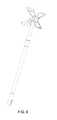
- FIG. 1is a perspective view of an exemplary device embodiment.
- FIG. 2is an exploded view of the device of FIG. 1 .
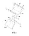
- FIG. 3is an exploded view of an exemplary head assembly.
- FIGS. 4 and 5depict an exemplary first (handle) portion
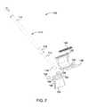
- FIGS. 6 and 7depict an exemplary second (scraper) portion.
- FIG. 8depicts an exemplary coupler member.
- FIGS. 9-11provide additional views of exemplary device embodiments.
- FIG. 12provides an additional exploded view of a device embodiment.
- FIG. 13shows additional views of exemplary embodiments.
- a device embodiment 100 for removing material from a surfaceincludes a rod assembly 110 and a tool head assembly 120 .
- Rod assembly 110includes an upper rod 112 , a telescoping rod 114 , and an adjustment mechanism 116 .
- Upper rod 112may be any suitable size, shape, length, or configuration and may be formed from any suitable material.
- the upper portion 112may be formed from a plastic (e.g., PP, LDPE, PC, ABS) and/or a metal (e.g., aluminum).
- upper rod 112may define a substantially annular shape and may be configured to receive at least a portion of the telescoping rod 114 .
- the upper rod 112may define an inner diameter (e.g., the inner diameter defined by the annular shape of the upper rod 112 ) and an outer diameter.
- the inner and outer diameter of the upper rod 112may be any suitable size.
- upper rod 112may include a handle portion 108 including an aperture.
- the handle portionmay be used to hang and/or store the device 100 .
- the device 100may be hung from the aperture on a hook, nail, and/or the like.
- the handle portionmay be formed from any suitable material or materials such as, for example, a plastic or rubber.
- the telescoping rod 114may be any suitable size, shape, length, or configuration and may be formed from any suitable material.
- the telescoping rod 114may be formed from the same or similar material as upper rod 112 .
- the telescoping rod 114may be configured to be operably coupled to the upper rod 112 , as described in further detail herein. More specifically, telescoping rod 114 may define an outer diameter configured to be slightly smaller than the inner diameter defined by the annular shape of the upper rod 112 . In this manner, an end of the telescoping rod 114 may be inserted into an end of the upper rod 112 .
- An adjustment mechanism 116may be rotatably coupled to the upper rod 112 and selectively coupled to the telescoping rod 114 .
- the adjustment mechanism 116may include a sleeve configured to selectively engage the telescoping rod 114 such that the sleeve maintains the position of the telescoping rod 114 with respect to the upper rod 112 .
- the adjustment mechanism 116may be rotated such that the sleeve tightens around an outer surface of the telescoping rod 114 .
- the telescoping rod 114may be positioned within the upper rod 112 such that the rod assembly is a desired length and the adjustment mechanism 116 can be rotated, thereby locking the telescoping rod 114 in the desired position relative to the upper rod 112 .
- the adjustment mechanism 116may be any suitable mechanism.
- a tool head assembly 120may include a first portion 130 , a second portion 150 , and a coupling member 160 .
- the first portion 130includes a grip 132 , a blade 136 , and a mount 138 .
- the first portion 130may be any suitable shape, size or configuration and may be formed from any suitable material.
- the first portion 130may be formed from a substantially rigid plastic or polymer.
- the first portion 130may be formed from a metal, such as, for example, aluminum.
- the first portion 130may define a substantially arcuate path.
- the mount 138may extend away from a convex surface of the arcuate path.
- the grip 132includes a rubber insert 134 configured to increase the ergonomics of the grip 132 . In this manner, the user of the device 100 may engage at least a portion of the grip 132 to control the tool head assembly 120 .
- the rubber insert 134may be configured to protect a surface (e.g., a painted surface) from grip 132 .
- grip 132may include an opening configured to receive a portion of a users hand when in use.
- the blade 136may be disposed about a protrusion 140 extending from a surface of the first portion 130 or disposed in a recess in the first portion 130 . In this manner, blade 136 may be used to remove material from a surface, as described in further detail herein.
- blade 136may be remove-ably or fixedly coupled to the first portion 130 .
- blade 136may be unitarily formed with the first portion 130 .
- blade 136may be a flexible rubber material (so that the blade functions as a “squeegee”), a rigid plastic material, or a metal such as, for example, stainless steel. In some embodiments, blade 136 may be a sharpened blade such as, for example, a razor blade.
- FIGS. 6 and 7illustrate an exemplary second portion 150 of the tool head assembly 120 .
- the second portion 150may include a scraping member 152 , a chipping member 154 , and a mount 156 .
- the second portion 150may be any suitable shape, size or configuration and may be formed from any suitable material.
- the second portion 150may be formed from a rigid plastic, polymer, metal, and/or the like.
- the second portion 150may define a substantially arcuate path.
- the mount 156may extend away from a convex surface of the arcuate path.
- the scraping member 152may include a relatively sharp edge configured to engage a surface to remove material from the surface.
- the scraping member 152may be configured to scrape ice from a surface, such as a window.
- the chipping member 154may include a relatively sharp edge that may be substantially serrated. In this manner, the chipping member 154 may be used to engage and chip away material from the surface.
- the coupling member 160is configured to engage the first portion 130 and the second portion 150 of the tool head assembly 120 . More specifically, the coupling member 160 may be configured to engage the mount 138 of the first portion 130 and the mount 156 of the second portion 150 . Additionally, the coupling member 160 may include protrusions 164 configured to engage a surface and/or surfaces of the first portion 130 and the second portion 150 to ensure the alignment of the first portion 130 relative to the second portion 150 . In this manner, the first portion 130 and the second portion 150 may receive, for example, a set of screws, such that the first portion 130 , the second portion 150 , and the coupling member 160 are coupled together.
- the coupling portion 160may include an opening 162 configured to receive a mounting portion 118 of the telescoping rod 114 .
- the coupling member 160 and the mounting portion 118may receive, for example, a set of screws, such that the telescoping rod 114 and the coupling member 160 may be coupled together.
- the arrangement of the coupling member 160 , the mounting portion 118 , the first portion 130 , and the second portion 150may facilitate coupling of rod assembly 110 to tool head assembly 120 .
- mounting portion 118may be threaded and the coupling member 160 may be configured to receive a threaded rod.
- the coupling member 160may be configured to receive the mounting portion 118 and a pin or other mechanical fastener may be used to secure the rod assembly 110 to the head assembly.
- the device 100may be engaged by user to remove material from a surface, such as, ice from the surface of a window, wallpaper from a wall, a laminate from a floor or piece of furniture, and/or the like.
- a usermay engage the device 100 to remove ice and/or snow from a window or other surface (e.g., the roof or hood of a car).
- the usermay engage the rod assembly 110 and adjust the rod assembly 110 to the desired length, via the adjustment member 116 . With the length of the rod assembly 110 adjusted, the user may engage the grip 132 and place the scraping member 152 in contact with the ice covered window.
- the usermay move the device 100 relative to the window, such that the scraping member 152 scrapes the ice from the window. If all of the desired amount of ice is not removed from the window, the user may move the device 100 such that the chipping member 154 may engage the ice. In this manner, portions of the ice that were not removed by the scraping member 152 may be removed by the chipping member 154 without the need for a secondary tool or device. With the desired amount of ice removed, the device 100 may be rotated such that the blade 136 can engage the surface of the window to remove ice, snow, or other debris from the surface.
Landscapes
- Cleaning Implements For Floors, Carpets, Furniture, Walls, And The Like (AREA)
Abstract
Description
Claims (49)
Priority Applications (1)
| Application Number | Priority Date | Filing Date | Title |
|---|---|---|---|
| US13/737,766US9101253B2 (en) | 2012-01-11 | 2013-01-09 | Apparatus and methods for removing material from a surface |
Applications Claiming Priority (3)
| Application Number | Priority Date | Filing Date | Title |
|---|---|---|---|
| US201261585472P | 2012-01-11 | 2012-01-11 | |
| US29/410,753USD705511S1 (en) | 2012-01-11 | 2012-01-11 | Scraping device |
| US13/737,766US9101253B2 (en) | 2012-01-11 | 2013-01-09 | Apparatus and methods for removing material from a surface |
Related Parent Applications (1)
| Application Number | Title | Priority Date | Filing Date |
|---|---|---|---|
| US29/410,753Continuation-In-PartUSD705511S1 (en) | 2012-01-11 | 2012-01-11 | Scraping device |
Publications (2)
| Publication Number | Publication Date |
|---|---|
| US20130174367A1 US20130174367A1 (en) | 2013-07-11 |
| US9101253B2true US9101253B2 (en) | 2015-08-11 |
Family
ID=48781872
Family Applications (1)
| Application Number | Title | Priority Date | Filing Date |
|---|---|---|---|
| US13/737,766Expired - Fee RelatedUS9101253B2 (en) | 2012-01-11 | 2013-01-09 | Apparatus and methods for removing material from a surface |
Country Status (3)
| Country | Link |
|---|---|
| US (1) | US9101253B2 (en) |
| CA (1) | CA2862901A1 (en) |
| WO (1) | WO2013106469A1 (en) |
Cited By (6)
| Publication number | Priority date | Publication date | Assignee | Title |
|---|---|---|---|---|
| USD752941S1 (en)* | 2013-06-04 | 2016-04-05 | Jeff Lee | Scaling and scraping hammer |
| USD845571S1 (en)* | 2017-10-19 | 2019-04-09 | Rubbermaid Commercial Products Llc | 3-in-1 floor tool |
| US10710122B2 (en)* | 2016-03-23 | 2020-07-14 | Hal P. Greenberger | Material removal from surfaces |
| RU213076U1 (en)* | 2022-05-06 | 2022-08-23 | Федеральное государственное бюджетное образовательное учреждение высшего образования "Елецкий государственный университет им. И.А. Бунина" | DEVICE FOR REMOVING SNOW FROM GREENHOUSE ROOF |
| US20220379349A1 (en)* | 2021-05-25 | 2022-12-01 | Halo Products Group, Llc | Griddle Utensil With Scraper and Squeegee |
| IL297142A (en)* | 2022-10-06 | 2024-01-01 | Tyroler Ltd | A wiping tool |
Families Citing this family (6)
| Publication number | Priority date | Publication date | Assignee | Title |
|---|---|---|---|---|
| US20150096137A1 (en)* | 2013-10-09 | 2015-04-09 | Adam Lyle Kayler | Grout cleaning device |
| US10178929B2 (en)* | 2014-09-09 | 2019-01-15 | Masahiro Takaki | Removable washer |
| US20160144834A1 (en)* | 2014-11-26 | 2016-05-26 | II Charles E. Bryant | Ice scraper and method of use |
| ITUB20154912A1 (en)* | 2015-10-20 | 2017-04-20 | Techfood Snc Di Iori Angelo E Castagnetti Paola | SPATULA FOR CULINARY USE |
| CN108710698B (en)* | 2018-05-23 | 2021-10-15 | 湖南大学 | Multi-keyword fuzzy query method based on ciphertext in cloud environment |
| CN108993929A (en)* | 2018-08-01 | 2018-12-14 | 穆科明 | A kind of dual-machine linkage industrial machine vision automatic checkout system |
Citations (12)
| Publication number | Priority date | Publication date | Assignee | Title |
|---|---|---|---|---|
| US3214834A (en)* | 1964-02-07 | 1965-11-02 | Terrel H Bell | Ice and frost scraper for windshields |
| US4091579A (en) | 1976-05-24 | 1978-05-30 | Clayton Giangiulio | Scraper |
| US4305175A (en)* | 1980-03-24 | 1981-12-15 | Burgess Jr Freeman L | Scraping tool |
| US5263222A (en) | 1992-06-01 | 1993-11-23 | Johnstone Ii James R | Automotive windshield ice scraper |
| US6216306B1 (en) | 1999-08-13 | 2001-04-17 | The Coleman Company, Inc. | Grill cleaning brush and scraper |
| US6243906B1 (en)* | 1999-01-25 | 2001-06-12 | Prestone Products Corporation | Ice scraper assembly |
| USD460589S1 (en) | 2001-11-15 | 2002-07-16 | Marvin I. Weinberger | Ice scraper |
| US7249393B2 (en)* | 2001-06-15 | 2007-07-31 | Innovation Factory, Inc. | Ice scraper |
| US20080034525A1 (en)* | 2006-08-09 | 2008-02-14 | A. Richard S.E.N.C. | Wallpaper scraper |
| US20090188061A1 (en) | 2006-03-10 | 2009-07-30 | Cybulski Eric R | Heated food preparation surface cleaning system |
| US20090217471A1 (en) | 2008-01-31 | 2009-09-03 | Innovation Factory, Inc. | Brush Assembly |
| US20100186183A1 (en) | 2009-01-23 | 2010-07-29 | Miw Associates, Llc | Ice scraper |
- 2013
- 2013-01-09WOPCT/US2013/020883patent/WO2013106469A1/enactiveApplication Filing
- 2013-01-09USUS13/737,766patent/US9101253B2/ennot_activeExpired - Fee Related
- 2013-01-09CACA2862901Apatent/CA2862901A1/ennot_activeAbandoned
Patent Citations (14)
| Publication number | Priority date | Publication date | Assignee | Title |
|---|---|---|---|---|
| US3214834A (en)* | 1964-02-07 | 1965-11-02 | Terrel H Bell | Ice and frost scraper for windshields |
| US4091579A (en) | 1976-05-24 | 1978-05-30 | Clayton Giangiulio | Scraper |
| US4305175A (en)* | 1980-03-24 | 1981-12-15 | Burgess Jr Freeman L | Scraping tool |
| US5263222A (en) | 1992-06-01 | 1993-11-23 | Johnstone Ii James R | Automotive windshield ice scraper |
| US6243906B1 (en)* | 1999-01-25 | 2001-06-12 | Prestone Products Corporation | Ice scraper assembly |
| US6216306B1 (en) | 1999-08-13 | 2001-04-17 | The Coleman Company, Inc. | Grill cleaning brush and scraper |
| US7526831B2 (en) | 2001-06-15 | 2009-05-05 | Innovation Factory, Inc. | Ice scraper |
| US7249393B2 (en)* | 2001-06-15 | 2007-07-31 | Innovation Factory, Inc. | Ice scraper |
| US7814610B2 (en) | 2001-06-15 | 2010-10-19 | Innovation Factory, Inc. | Ice scraper |
| USD460589S1 (en) | 2001-11-15 | 2002-07-16 | Marvin I. Weinberger | Ice scraper |
| US20090188061A1 (en) | 2006-03-10 | 2009-07-30 | Cybulski Eric R | Heated food preparation surface cleaning system |
| US20080034525A1 (en)* | 2006-08-09 | 2008-02-14 | A. Richard S.E.N.C. | Wallpaper scraper |
| US20090217471A1 (en) | 2008-01-31 | 2009-09-03 | Innovation Factory, Inc. | Brush Assembly |
| US20100186183A1 (en) | 2009-01-23 | 2010-07-29 | Miw Associates, Llc | Ice scraper |
Non-Patent Citations (1)
| Title |
|---|
| The above references were cited in the International Search Report issued on Mar. 26, 2013, in International Application No. PCT/US13/20883. |
Cited By (12)
| Publication number | Priority date | Publication date | Assignee | Title |
|---|---|---|---|---|
| USD752941S1 (en)* | 2013-06-04 | 2016-04-05 | Jeff Lee | Scaling and scraping hammer |
| US10710122B2 (en)* | 2016-03-23 | 2020-07-14 | Hal P. Greenberger | Material removal from surfaces |
| US20200298281A1 (en)* | 2016-03-23 | 2020-09-24 | Hal P. Greenberger | Material Removal from Surfaces |
| US11453034B2 (en)* | 2016-03-23 | 2022-09-27 | Hal P. Greenberger | Material removal from surfaces |
| USD845571S1 (en)* | 2017-10-19 | 2019-04-09 | Rubbermaid Commercial Products Llc | 3-in-1 floor tool |
| US20220379349A1 (en)* | 2021-05-25 | 2022-12-01 | Halo Products Group, Llc | Griddle Utensil With Scraper and Squeegee |
| US12208424B2 (en)* | 2021-05-25 | 2025-01-28 | Wh Products, Llc | Griddle utensil with scraper and squeegee |
| RU213076U1 (en)* | 2022-05-06 | 2022-08-23 | Федеральное государственное бюджетное образовательное учреждение высшего образования "Елецкий государственный университет им. И.А. Бунина" | DEVICE FOR REMOVING SNOW FROM GREENHOUSE ROOF |
| IL297142A (en)* | 2022-10-06 | 2024-01-01 | Tyroler Ltd | A wiping tool |
| IL297142B1 (en)* | 2022-10-06 | 2024-01-01 | Tyroler Ltd | A wiping tool |
| WO2024075115A1 (en)* | 2022-10-06 | 2024-04-11 | Tyroler Ltd. | A wiping tool |
| IL297142B2 (en)* | 2022-10-06 | 2024-05-01 | Tyroler Ltd | mop |
Also Published As
| Publication number | Publication date |
|---|---|
| US20130174367A1 (en) | 2013-07-11 |
| WO2013106469A1 (en) | 2013-07-18 |
| CA2862901A1 (en) | 2013-07-18 |
Similar Documents
| Publication | Publication Date | Title |
|---|---|---|
| US9101253B2 (en) | Apparatus and methods for removing material from a surface | |
| US9345314B2 (en) | Automotive snow brush with squeegee | |
| US20140217759A1 (en) | Combination snow shovel and ice scraper | |
| US9611603B2 (en) | Convertible tool | |
| CA2980872C (en) | Shovel assembly | |
| US8756747B2 (en) | Twin bladed scraper tool | |
| US5263222A (en) | Automotive windshield ice scraper | |
| CA2746710A1 (en) | Tool with ergonomic handle and replaceable cutter head | |
| EP2377447A1 (en) | Bent mop handle and a mop having such a mop handle | |
| US9573265B2 (en) | Arm holder for a pole-handled tool | |
| US8832898B1 (en) | Two-handed scraping device | |
| US8267754B2 (en) | Skinning knife | |
| US5400510A (en) | Windshield glass knife brace | |
| CA2253172A1 (en) | Scraping tool | |
| US20160066761A1 (en) | Dual-bladed scraper with a rotatable blade-retaining head | |
| US20180163356A1 (en) | Shovel and related methods | |
| CA2790442C (en) | Dual purpose snowmobile snow flap | |
| US6757930B2 (en) | Ice scraper with brush and the glove | |
| US20240341557A1 (en) | Scraping Assembly | |
| US20120011675A1 (en) | Tool for removing acoustic ceiling material | |
| US20120279006A1 (en) | Thick and Thin Ice Scraper | |
| GB2511167A (en) | An Ice Scraper | |
| AU2010100083B4 (en) | Extendable razor | |
| KR101542321B1 (en) | A towel for knife and a knife having the same | |
| KR20180130768A (en) | Knife towel for knife and stone for knife and anti knife frame |
Legal Events
| Date | Code | Title | Description |
|---|---|---|---|
| AS | Assignment | Owner name:QUIRKY, INC., NEW YORK Free format text:ASSIGNMENT OF ASSIGNORS INTEREST;ASSIGNORS:JOHNSTONE, JIM;JACOBSEN, JOHN THOMAS;FUGLER, JESSICA;SIGNING DATES FROM 20130107 TO 20130109;REEL/FRAME:029599/0048 | |
| AS | Assignment | Owner name:COMERICA BANK, MICHIGAN Free format text:SECURITY INTEREST;ASSIGNOR:QUIRKY, INC.;REEL/FRAME:032794/0873 Effective date:20140422 | |
| ZAAA | Notice of allowance and fees due | Free format text:ORIGINAL CODE: NOA | |
| ZAAB | Notice of allowance mailed | Free format text:ORIGINAL CODE: MN/=. | |
| STCF | Information on status: patent grant | Free format text:PATENTED CASE | |
| AS | Assignment | Owner name:Q HOLDINGS LLC, NEW YORK Free format text:ASSET PURCHASE AGREEMENT;ASSIGNOR:QUIRKY, INC.;REEL/FRAME:038805/0487 Effective date:20151125 | |
| AS | Assignment | Owner name:Q HOLDINGS LLC, NEW YORK Free format text:CORRECTIVE ASSIGNMENT TO CORRECT THE PAT. NO. 9,137,104 PREVIOUSLY RECORDED ON REEL 038805 FRAME 0487. ASSIGNOR(S) HEREBY CONFIRMS THE ASSET PURCHASE AGREEMENT;ASSIGNOR:QUIRKY, INC.;REEL/FRAME:040980/0001 Effective date:20151124 | |
| AS | Assignment | Owner name:Q HOLDINGS LLC, NEW YORK Free format text:ASSET PURCHASE AGREEMENT;ASSIGNOR:QUIRKY, INC.;REEL/FRAME:040342/0417 Effective date:20151125 Owner name:Q HOLDINGS LLC, NEW YORK Free format text:RESUBMISSION;ASSIGNOR:QUIRKY, INC.;REEL/FRAME:040342/0417 Effective date:20151125 | |
| AS | Assignment | Owner name:QUIRKY IP LICENSING LLC, NEW YORK Free format text:ASSIGNMENT OF ASSIGNORS INTEREST;ASSIGNOR:Q HOLDINGS LLC;REEL/FRAME:045215/0283 Effective date:20180123 | |
| AS | Assignment | Owner name:BANK HAPOALIM B.M., NEW YORK Free format text:SECURITY INTEREST;ASSIGNOR:QUIRKY IP LICENSING LLC;REEL/FRAME:047238/0915 Effective date:20180731 | |
| MAFP | Maintenance fee payment | Free format text:PAYMENT OF MAINTENANCE FEE, 4TH YR, SMALL ENTITY (ORIGINAL EVENT CODE: M2551); ENTITY STATUS OF PATENT OWNER: SMALL ENTITY Year of fee payment:4 | |
| FEPP | Fee payment procedure | Free format text:MAINTENANCE FEE REMINDER MAILED (ORIGINAL EVENT CODE: REM.); ENTITY STATUS OF PATENT OWNER: SMALL ENTITY | |
| LAPS | Lapse for failure to pay maintenance fees | Free format text:PATENT EXPIRED FOR FAILURE TO PAY MAINTENANCE FEES (ORIGINAL EVENT CODE: EXP.); ENTITY STATUS OF PATENT OWNER: SMALL ENTITY | |
| STCH | Information on status: patent discontinuation | Free format text:PATENT EXPIRED DUE TO NONPAYMENT OF MAINTENANCE FEES UNDER 37 CFR 1.362 | |
| FP | Lapsed due to failure to pay maintenance fee | Effective date:20230811 |