US9101090B2 - Windrower autoguidance hydraulic steering interface - Google Patents
Windrower autoguidance hydraulic steering interfaceDownload PDFInfo
- Publication number
- US9101090B2 US9101090B2US13/905,528US201313905528AUS9101090B2US 9101090 B2US9101090 B2US 9101090B2US 201313905528 AUS201313905528 AUS 201313905528AUS 9101090 B2US9101090 B2US 9101090B2
- Authority
- US
- United States
- Prior art keywords
- steering
- rotation
- input shaft
- control
- valve
- Prior art date
- Legal status (The legal status is an assumption and is not a legal conclusion. Google has not performed a legal analysis and makes no representation as to the accuracy of the status listed.)
- Expired - Fee Related, expires
Links
- 230000007246mechanismEffects0.000claimsdescription20
- 239000012530fluidSubstances0.000claimsdescription19
- 230000033001locomotionEffects0.000claimsdescription17
- 230000001419dependent effectEffects0.000claimsdescription5
- 238000006073displacement reactionMethods0.000claimsdescription5
- 230000008859changeEffects0.000claimsdescription4
- 230000000694effectsEffects0.000abstractdescription5
- 230000002706hydrostatic effectEffects0.000description13
- 230000007935neutral effectEffects0.000description6
- 230000008901benefitEffects0.000description4
- 230000008878couplingEffects0.000description4
- 238000010168coupling processMethods0.000description4
- 238000005859coupling reactionMethods0.000description4
- 230000007423decreaseEffects0.000description3
- 238000007792additionMethods0.000description2
- 238000004378air conditioningMethods0.000description1
- 230000003466anti-cipated effectEffects0.000description1
- 230000000903blocking effectEffects0.000description1
- 230000003750conditioning effectEffects0.000description1
- 230000003247decreasing effectEffects0.000description1
- 238000010586diagramMethods0.000description1
- 230000026058directional locomotionEffects0.000description1
- 239000000463materialSubstances0.000description1
- 230000013011matingEffects0.000description1
- 238000000034methodMethods0.000description1
- 230000008569processEffects0.000description1
- 230000004044responseEffects0.000description1
- 230000035945sensitivityEffects0.000description1
- 230000000087stabilizing effectEffects0.000description1
Images


Classifications
- A—HUMAN NECESSITIES
- A01—AGRICULTURE; FORESTRY; ANIMAL HUSBANDRY; HUNTING; TRAPPING; FISHING
- A01D—HARVESTING; MOWING
- A01D34/00—Mowers; Mowing apparatus of harvesters
- A01D34/006—Control or measuring arrangements
- A01D34/008—Control or measuring arrangements for automated or remotely controlled operation
- A—HUMAN NECESSITIES
- A01—AGRICULTURE; FORESTRY; ANIMAL HUSBANDRY; HUNTING; TRAPPING; FISHING
- A01D—HARVESTING; MOWING
- A01D69/00—Driving mechanisms or parts thereof for harvesters or mowers
- A01D69/03—Driving mechanisms or parts thereof for harvesters or mowers fluid
- A—HUMAN NECESSITIES
- A01—AGRICULTURE; FORESTRY; ANIMAL HUSBANDRY; HUNTING; TRAPPING; FISHING
- A01D—HARVESTING; MOWING
- A01D34/00—Mowers; Mowing apparatus of harvesters
- A—HUMAN NECESSITIES
- A01—AGRICULTURE; FORESTRY; ANIMAL HUSBANDRY; HUNTING; TRAPPING; FISHING
- A01D—HARVESTING; MOWING
- A01D41/00—Combines, i.e. harvesters or mowers combined with threshing devices
- A01D41/12—Details of combines
- A01D41/127—Control or measuring arrangements specially adapted for combines
- A01D41/1274—Control or measuring arrangements specially adapted for combines for drives
- A—HUMAN NECESSITIES
- A01—AGRICULTURE; FORESTRY; ANIMAL HUSBANDRY; HUNTING; TRAPPING; FISHING
- A01D—HARVESTING; MOWING
- A01D41/00—Combines, i.e. harvesters or mowers combined with threshing devices
- A01D41/12—Details of combines
- A01D41/127—Control or measuring arrangements specially adapted for combines
- A01D41/1278—Control or measuring arrangements specially adapted for combines for automatic steering
- B—PERFORMING OPERATIONS; TRANSPORTING
- B62—LAND VEHICLES FOR TRAVELLING OTHERWISE THAN ON RAILS
- B62D—MOTOR VEHICLES; TRAILERS
- B62D11/00—Steering non-deflectable wheels; Steering endless tracks or the like
- B62D11/001—Steering non-deflectable wheels; Steering endless tracks or the like control systems
- B62D11/005—Hydraulic control systems
Definitions
- the present inventionrelates generally to hydraulically powered differential steered agricultural machines, and more particularly to an autoguidance interface for a hydraulic steering system for such a machine
- Hydrostatic drive systemsare often configured with the drive pump attached directly to the engine without a clutch or other mechanism to stop output flow of the pump while the engine is running.
- Drive pump displacement (output) and therefore speed in differential-steered machinesis controlled by variations in swashplate angle which is adjusted by movement of external pintel arms external to the pumps.
- pintel arm and thus swashplate rotation from “neutral” to “full speed”occurs over a relatively narrow range on the order of 16-18 degrees. With such a small range of motion, it is important that the assembly controlling the angular position of the pintel arm angles be capable of precise angular control.
- Precise control of the swashplate angle for hydrostatic ground drive pumps on differential-steered agricultural machinesis paramount, especially when operating the machine at higher travel speed such as is necessary for road transport between fields.
- One common conventional mechanical mechanismuses an input shaft that may be rotated and moved fore-and-aft along its longitudinal axis. Threaded portions on the input shaft, one right-hand threaded and one left-hand threaded, are engaged by mating threaded followers that are connected to the pintel arms on a pair of pumps connected in tandem alongside the input shaft. Rotation of the input shaft result in the followers moving along the threaded portions, either toward each other or away from each other. The result is that the pintel arms are rotated in opposite directions as the input shaft is rotated resulting in opposing changes in the hydraulic pump output to the drive motors (e.g., one increases speed while the other decreases speed). Rotation of the input shaft is directed by a steering wheel located in the operator cab of the machine. Fore and aft movement of the input shaft does not adjust the relative rotational position of the pintel arms, but instead rotates the pintel arms in the same direction by the same degree and is used to adjust the machine travel speed and select between forward and reverse directional movement.
- Autoguidance systemsare increasingly being fitted to agricultural machines in the quest for ever-improving efficiency. As autoguidance systems become more prevalent in agricultural machines, windrowers and the like are being fitted with autoguidance systems. Incorporating autoguidance systems into an existing machine typically involves the addition of actuators or other mechanical adapters to allow the autoguidance steering actuators to interface with the manual steering system already existing on the machine. Such additions add complexity and cost and may not provide the reliability of a more integrated approach.
- a hydrostatic drive differential-steered machinehaving left- and right-side drive pumps tandem-mounted to an engine, each drive pump having an angularly adjustable swash plate moveable by a pivoting pintel arm and a control linkage for simultaneously moving the pintel arms.
- the pintel armsare moveable in a range from full forward speed to full reverse speed with an intermediate neutral position to enable forward and reverse travel as well as turning of the machine.
- the control linkageis configured to move the pintel arms in unison by linear motion of the control linkage and to move the pintel arms in opposition by rotary motion of the control linkage.
- a first input to the control linkageis by a hydraulic steering motor to rotate the control linkage for steering the machine by adjusting the differential speed of the left and right wheels.
- a steering control valve connected to a steering wheelmanages the input for rotating the hydraulic steering motor.
- the steering control valveis selected to produce a steering gain (e.g., the turn rate of the steering motor is greater than the turn rate of the steering wheel) allowing the increased precision in the interface between the control linkage and the pintel arms.
- a second input to the control linkageis a linear actuator, movement of which is managed by a forward-neutral-reverse (FNR) lever accessible to the machine operator, to adjust the speed of the wheels uniformly.
- the linear actuatoris connected at one end to the control linkage and to a bracket connected to the drive pumps at the opposite end so that the linear actuator and the pumps share a common anchorage, namely the resiliently mounted engine and hydraulic pumps, further improving steering precision and sensitivity.
- An autoguidance systemis provided on the machine.
- the systemcompares the position and direction of travel of the machine to a programmed or calculated track and generates signals which may be used by a steering control apparatus to adjust the travel direction of the machine to match the desired track.
- the autoguidance steering signalsare directed to a proportional steering valve that is hydraulically connected to the hydraulic circuit between the manual steering control valve and the steering drive motor by an enabling manifold.
- the manifoldallows either the manual steering control valve or the autoguidance steering valve to provide the directional inputs for the steering drive motor without the need for additional steering actuators or mechanisms on the machine.
- an autoguidance interface for a hydraulic steering system for a differential steered self-propelled agricultural windroweris provided. Windrower speed and direction are controlled by adjustment to a control input shaft to control the output of a pair of tandem-mounted hydraulic drive pumps and provide motive power for the windrower.
- the control input shaftis rotatable and axially moveable.
- a hydraulic steering motoris operably connected to the input shaft to effect control input shaft rotation. Rotation of the hydraulic steering motor is selectively managed by a steering control valve attached to a cab-mounted windrower steering wheel or a proportional steering valve managed by the autoguidance system.
- a selector valvecontrols the active steering input. An emergency disengagement positions the selector valve to restore manual control by the steering wheel.
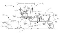
- FIG. 1is a side elevation view of a known differential steered agricultural windrower of the type with which the instant invention finds utility;
- FIG. 2is a partial left side view of the hydrostatic control system for the windrower of FIG. 1 showing the drive pump control mechanism, mounting, and hydraulic interface;
- FIG. 3is a diagram of a first embodiment of the hydraulic steering control circuit with autoguidance interface for the windrower of FIG. 1 .
- FIG. 1illustrates an agricultural machine 5 of the type on which the present invention finds utility.
- the machine 5 illustratedis a well-known, self-propelled agricultural windrower employing differential speed of the driving wheels to steer the machine across the ground.
- the machinecomprises a main frame 10 with a longitudinal horizontal axis from front to back, supported by a pair of drive wheels 13 on the front portion thereof and by a pair of steering caster wheels 11 adjacent to the rear end.
- the main frame 10supports an operator cab 17 to provide an environmentally controlled location from which the machine may be comfortably operated, and a forwardly disposed header 19 .
- Header 19may be of several designs, but typically comprises a cutting mechanism, either a sickle bar or rotary cutter, a feeder mechanism and, on some models, conditioning rolls.
- Power to the machineis provided by an engine 12 which is resiliently connected by isolators 122 to the main frame 10 to reduce vibration transmitted into the main frame 10 by the engine 12 .
- the general mode of operation of a modern differential steered agricultural machineis to have tandem hydrostatic pumps 14 , 16 , one for each of two drive wheels 13 , each pump having a depending pintel arm such that forward and reverse movement of the pintel arm relative to a neutral position pivots a swashplate in the associated hydrostatic pump allowing adjustment of the flow rate and flow direction, thus causing the associated drive motor 23 and wheel to rotate.
- the hydrostatic drive pumps 14 , 16are mounted in tandem directly to the engine 12 .
- Control of the drive pumps from the operator cab 17is accomplished by operator input from a steering wheel 18 (turning control) and a forward-neutral-reverse (FNR) speed selector 22 operably connected to a drive control mechanism 30 adjacent to the drive pumps 14 , 16 .
- a steering wheel 18turning control
- FNRforward-neutral-reverse
- a vehicle autoguidance system 300comprising an operator interface, a GPS receiver, and computer. The system compares then current position with a desired track and generates one or more steering correction signals representative of steering inputs necessary to steer the vehicle to and maintain its position on the desired track.
- Such systemsgenerally include an operator interface to allow a machine operator to monitor the autoguidance system, define or memorize a desired track for the machine to follow, make on-the-fly track adjustments to the track, and engage or disengage the system. Most systems will disengage whenever the machine operator makes a manual adjustment, such as turning the steering wheel, to enhance operational safety.
- the operation of agricultural autoguidance systemsis well-known and not discussed in detail beyond the capability of the system to initiate a steering signal indicative of a desired steering input.
- the present inventionreceives a steering input signal initiated by an autoguidance system and effects vehicle turning through an interface with a manual, hydraulic steering system on the vehicle.
- the inventionalso includes an interface for automatically disengaging the autoguidance control and reverting to manual steering in response to certain operator actions.
- an exemplar hydrostatic control systemis shown to include a conventional steering wheel 18 inside the operator's cab 17 .
- the cabwould, of course, include additional components (not shown) such as a seat, electrical and mechanical controls for operation of the machine, an air conditioning unit, and the like.
- the steering wheel 18is attached to a rotatable steering shaft 182 that is connected to a steering control valve 185 which directs a flow of pressurized hydraulic fluid to a steering drive motor 187 .
- Pressurized hydraulic fluidis provided to the steering control valve by a hydraulic pump 15 .
- pump 15describes the combination of a hydraulic pump, relief valves, connection lines, orifii, and reservoir (tank 151 ) necessary to provide a specified flow of pressurized fluid to a control device, such as the instant steering control valve, and allow the device to function.
- An output shaft 189 from the steering drive motoris, in turn, connected to the drive control mechanism 30 by a universal joint 188 and a sliding coupling 184 .
- the drive control mechanism 30comprises a control input shaft 311 that engages pintel arms 142 , 162 via internally threaded blocks 144 , 164 to operably connect the control input shaft to the respective left and right hydrostatic drive pumps 14 , 16 .
- the pintel arm blocks 144 , 164engage drive threads 314 , 316 on the control input shaft.
- the drive threads 314 , 316are reversed in relation to each other (one having right-hand thread and the other having left-hand threads) so that rotation of the input shaft 311 causes the blocks 144 , 164 to move in opposite directions, either toward one another or away from one another dependent upon the rotation direction of the input shaft 311 .
- This opposing motionin turn causes the pintel arms 142 , 162 to rotate in opposite directions, one pintel arm rotating in a clockwise direction and the other rotating in a counter-clockwise direction, when viewed from the side, and alters the displacement of the drive pumps in an opposing manner (e.g., increase output flow in one while decreasing output flow in the other) allowing the machine to be steered by movement of the steering wheel 18 .
- thiscauses one drive pump to increase flow and the other to decrease flow, turning the machine; however, if the system is already in mechanical neutral, turning the steering wheel 18 increases flow in both pumps, but in opposite directions—the machine turning around itself with one drive wheel 13 going forward and one going in reverse.
- Control input shaft 311is also moveable axially to control the drive pumps 14 , 16 .
- the steering drive motor output shaft 189includes a sliding coupling comprising sleeve 184 and splined end 312 for connecting to the control input shaft 311 .
- the splined interfaceallows longitudinal movement of the control input shaft 311 relative to the output shaft 189 .
- the pintel arm blocks 144 , 164are moved forwardly or rearwardly causing the pintel arms 142 , 162 to rotate in the same direction (either clockwise or counter-clockwise).
- Within cab 17is the FNR lever 22 that is continuously and selectively movable to allow a change in speed of the machine in either the forward or reverse directions.
- Output 221 from the FNR lever 22controls a hydraulic valve 24 which causes FNR actuator 330 to extend or retract.
- Actuator 330is connected at first end 332 to a spindle 319 on knuckle 318 which is mounted on control input shaft 311 .
- the knuckle 318allows rotation of the input shaft 311 while maintaining a fixed axial position on the shaft.
- An opposing second end 331 of actuator 330is fixed in relation to the drive pumps 14 , 16 by connection to bracket 320 .
- a stabilizing linkageis provided to guide movement of the knuckle 318 to avoid deflecting the input shaft 311 from its longitudinal axis and further improves movement of the control input shaft 311 .
- a neutral bias element 350connects between the control input shaft 311 and the bracket 320 to bias the control input shaft 311 into a neutral position, that is one in which the drive pump output flows are essentially zero when the steering control is aligned for straight-ahead travel.
- the steering drive motor 187is connected to the main frame 10 and positioned proximate to the steering input shaft 30 .
- An output shaft 189 from the steering drive motoris connected to the drive control mechanism 30 by a universal joint 188 and a sliding coupling 184 .
- the connectionallows minor axial misalignment between the steering drive motor 187 and the drive control mechanism 30 without resulting in binding or excessive wear in the motor or the mechanism.
- a pressurized fluid supply provided by pump 15 via supply line 152is metered by steering control valve 185 and causes the steering drive motor 187 to rotate, the direction of rotation being dependent upon the rotation of the steering wheel 18 .
- the steering control valve 185directs pressurized fluid to the steering drive motor 187 via hydraulic lines 186 based on the turning input of steering wheel 18 . For example, turning the steering wheel to the right directs pressurized fluid needed to rotate the steering drive motor in the direction necessary to cause right turning of the vehicle. A steady positioning of the wheel 18 (e.g., no directional change necessary) results in no fluid flow being directed to the steering drive motor and thus no movement of the control input shaft; the machine will continue with the same relative drive pump displacements along the same trajectory.
- Relief flow from the steering control valve 185is returned to a fluid reservoir (tank) 151 by return line 154 .
- An output shaft 189 from the steering drive motoris connected to the drive control mechanism 30 by a universal joint 188 and a sliding coupling 184 .
- An enabling valve 210 and an autoguidance steering valve 220are hydraulically connected into the steering control circuit to provide a steering interface for the autoguidance system 300 .
- the connectionis generally in parallel with the manual steering control valve 185 .
- Enabling valve 210is a conventional blocking valve that is shiftable between positions to enable or disable the associated hydraulic circuit.
- pressurized hydraulic fluid from pump 15is directed to the autoguidance steering valve 220 .
- Autoguidance steering control valveis a proportional steering valve, functionally similar to manual steering control valve 185 , that is, it receives steering input signals from the autoguidance system 300 and directs a flow of pressurized hydraulic fluid based on the input signal to the steering drive motor 187 to manage the direction of travel of the machine.
- Hydraulic fluid output from the autoguidance steering valve 220 directed to the steering drive motor 187rotates the steering input shaft 30 with the same effect as previously described for manual steering.
- the autoguidance steering valve 220controls the steering drive motor 187 , which is already present on the machine so no additional actuators or mechanical interfaces with the steering input shaft are necessary.
- the pressurized fluid supply from pump 15is blocked, preventing the autoguidance steering control valve from directing pressurized hydraulic fluid to the steering drive motor 187 .
- the manual steering systemis unaffected by the presence of the blocked autoguidance interface.
- a safety disengage featuremay be easily incorporated when the vehicle is being steered by autoguidance.
- the autoguidance systemupon detecting movement of the steering wheel by a steering wheel sensor 301 , initiates a signal to shift the enabling valve 210 to the disabled position and isolate the input signal to the autoguidance control valve 220 . These steps returns control of the vehicle travel direction to the operator via the steering wheel without any intervening or momentary loss of directional control to enhance operational safety of the machine.
Landscapes
- Life Sciences & Earth Sciences (AREA)
- Environmental Sciences (AREA)
- Engineering & Computer Science (AREA)
- Automation & Control Theory (AREA)
- Chemical & Material Sciences (AREA)
- Combustion & Propulsion (AREA)
- Transportation (AREA)
- Mechanical Engineering (AREA)
- Guiding Agricultural Machines (AREA)
- Non-Deflectable Wheels, Steering Of Trailers, Or Other Steering (AREA)
Abstract
Description
Claims (6)
Priority Applications (3)
| Application Number | Priority Date | Filing Date | Title |
|---|---|---|---|
| US13/905,528US9101090B2 (en) | 2013-05-30 | 2013-05-30 | Windrower autoguidance hydraulic steering interface |
| CN201410211915.7ACN104210540B (en) | 2013-05-30 | 2014-05-20 | Windrower autoguidance hydraulic steering interface |
| RU2014121989ARU2675523C2 (en) | 2013-05-30 | 2014-05-29 | Windrower autoguidance hydraulic steering interface |
Applications Claiming Priority (1)
| Application Number | Priority Date | Filing Date | Title |
|---|---|---|---|
| US13/905,528US9101090B2 (en) | 2013-05-30 | 2013-05-30 | Windrower autoguidance hydraulic steering interface |
Publications (2)
| Publication Number | Publication Date |
|---|---|
| US20140358354A1 US20140358354A1 (en) | 2014-12-04 |
| US9101090B2true US9101090B2 (en) | 2015-08-11 |
Family
ID=51986032
Family Applications (1)
| Application Number | Title | Priority Date | Filing Date |
|---|---|---|---|
| US13/905,528Expired - Fee RelatedUS9101090B2 (en) | 2013-05-30 | 2013-05-30 | Windrower autoguidance hydraulic steering interface |
Country Status (3)
| Country | Link |
|---|---|
| US (1) | US9101090B2 (en) |
| CN (1) | CN104210540B (en) |
| RU (1) | RU2675523C2 (en) |
Cited By (11)
| Publication number | Priority date | Publication date | Assignee | Title |
|---|---|---|---|---|
| US9763388B2 (en) | 2015-09-15 | 2017-09-19 | Cnh Industrial America Llc | Agricultural harvester having a header based heat exchanger |
| US9834248B2 (en) | 2016-01-15 | 2017-12-05 | Deere & Company | Vehicle guidance system with a stepper motor |
| US20180084710A1 (en)* | 2016-09-28 | 2018-03-29 | Deere & Company | System And Method For Guided Line Acquisitions |
| WO2019136260A1 (en) | 2018-01-04 | 2019-07-11 | Cnh Industrial America Llc | Draper header for harvester and methods of using the same |
| EP3530096A1 (en) | 2018-02-19 | 2019-08-28 | CNH Industrial Belgium NV | Harvester with feedback assembly |
| US10421484B2 (en) | 2017-06-30 | 2019-09-24 | Cnh Industrial America Llc | Rear axle steering system and methods of using the same |
| US10464602B2 (en) | 2017-06-30 | 2019-11-05 | Cnh Industrial America Llc | Limited slip differential drive system and methods of using the same |
| US11390319B2 (en) | 2019-07-10 | 2022-07-19 | Fema Corporation Of Michigan | Steering system with switchable load reaction valve |
| US11473693B2 (en) | 2020-06-26 | 2022-10-18 | Fema Corporation Of Michigan | Proportional hydraulic two-stage valve |
| US11540445B2 (en) | 2018-04-27 | 2023-01-03 | Cnh Industrial America Llc | Crop merger system for harvester and methods of using the same |
| US12016257B2 (en) | 2020-02-19 | 2024-06-25 | Sabanto, Inc. | Methods for detecting and clearing debris from planter gauge wheels, closing wheels and seed tubes |
Families Citing this family (3)
| Publication number | Priority date | Publication date | Assignee | Title |
|---|---|---|---|---|
| US20200224377A1 (en)* | 2019-01-10 | 2020-07-16 | Carlson Paving Products, Inc. | Extension adjusting assembly |
| CN109911011B (en)* | 2019-04-12 | 2023-11-14 | 第一拖拉机股份有限公司 | Automatic steering hydraulic system of crawler tractor |
| CN113357212B (en)* | 2021-06-07 | 2024-10-01 | 上海三一重机股份有限公司 | Walking deviation correcting method and device for working machine |
Citations (17)
| Publication number | Priority date | Publication date | Assignee | Title |
|---|---|---|---|---|
| US5590730A (en) | 1994-11-04 | 1997-01-07 | Samsung Heavy Industry Co., Ltd. | Straight travelling apparatus for construction vehicles |
| US5923270A (en) | 1994-05-13 | 1999-07-13 | Modulaire Oy | Automatic steering system for an unmanned vehicle |
| US6062332A (en) | 1998-09-08 | 2000-05-16 | Eaton Corporation | Hydrostatic vehicle drive system having improved control thereof |
| US20020133279A1 (en) | 2001-03-19 | 2002-09-19 | Noah Manring | Method and apparatus for controlling straight line travel of a tracked machine |
| US6549837B2 (en) | 2001-05-09 | 2003-04-15 | Caterpillar Inc | Automatic tracking control for work machines |
| US20060064222A1 (en)* | 2004-09-21 | 2006-03-23 | Accurtrak Systems Limited | Kit for providing an automatic steering system |
| US20060064216A1 (en)* | 2004-09-21 | 2006-03-23 | Accutrak Systems Limited | Automatic steering system |
| US20070016350A1 (en)* | 2005-07-16 | 2007-01-18 | Fackler Robert L | Apparatus and method for FNR calibration and testing neutral safety switch thresholds in an agricultural windrower |
| US20070017712A1 (en)* | 2005-07-21 | 2007-01-25 | Dunn James T | Tractor with hydraulic speed and steering control for steering at maximum speed |
| US7207581B2 (en)* | 2004-10-15 | 2007-04-24 | Cnh America Llc | Adjustable hydrostatic control system |
| US20080087488A1 (en) | 2005-06-14 | 2008-04-17 | Accutrak Systems Limited | System and Method for Automatic Steering |
| US20090095561A1 (en)* | 2007-10-05 | 2009-04-16 | Cnh America Llc | Hydraulic Steering System for a Vehicle |
| US20090242219A1 (en)* | 2008-03-27 | 2009-10-01 | James Thomas Dunn | Tractor with automatic steering arrangement |
| US20090272551A1 (en)* | 2008-05-01 | 2009-11-05 | Dennis Thompson | Automatic Steering System For An Agricultural Implement |
| US20120215395A1 (en)* | 2011-02-18 | 2012-08-23 | Aznavorian Todd S | System and method for automatic guidance control of a vehicle |
| US20140138166A1 (en)* | 2012-11-19 | 2014-05-22 | Macdon Industries Ltd. | Speed and Steering Control of a Hydraulically Driven Tractor |
| US20140138165A1 (en)* | 2012-11-20 | 2014-05-22 | Deere & Company | Steering control system for hydrostatically driven front vehicle ground wheels and steerable rear caster wheels |
Family Cites Families (4)
| Publication number | Priority date | Publication date | Assignee | Title |
|---|---|---|---|---|
| SU950212A1 (en)* | 1980-07-24 | 1982-08-15 | Предприятие П/Я Р-6130 | Apparatus for controlling self-propelled agricultural machine |
| DE3468613D1 (en)* | 1983-09-06 | 1988-02-18 | Deere & Co | Row sensing apparatus for a crop harvester |
| RU2277488C1 (en)* | 2004-12-30 | 2006-06-10 | Федеральное государственное образовательное учреждение высшего профессионального образования "Воронежский государственный аграрный университет им. К.Д. Глинки" (ФГОУ ВПО ВГАУ им. К.Д. Глинки) | Steering system of all-wheel-drive vehicle |
| US7200993B2 (en)* | 2005-03-31 | 2007-04-10 | Caterpillar Inc | Electro-hydraulic steering control system |
- 2013
- 2013-05-30USUS13/905,528patent/US9101090B2/ennot_activeExpired - Fee Related
- 2014
- 2014-05-20CNCN201410211915.7Apatent/CN104210540B/ennot_activeExpired - Fee Related
- 2014-05-29RURU2014121989Apatent/RU2675523C2/enactive
Patent Citations (19)
| Publication number | Priority date | Publication date | Assignee | Title |
|---|---|---|---|---|
| US5923270A (en) | 1994-05-13 | 1999-07-13 | Modulaire Oy | Automatic steering system for an unmanned vehicle |
| US5590730A (en) | 1994-11-04 | 1997-01-07 | Samsung Heavy Industry Co., Ltd. | Straight travelling apparatus for construction vehicles |
| US6062332A (en) | 1998-09-08 | 2000-05-16 | Eaton Corporation | Hydrostatic vehicle drive system having improved control thereof |
| US20020133279A1 (en) | 2001-03-19 | 2002-09-19 | Noah Manring | Method and apparatus for controlling straight line travel of a tracked machine |
| US6549837B2 (en) | 2001-05-09 | 2003-04-15 | Caterpillar Inc | Automatic tracking control for work machines |
| US20060064222A1 (en)* | 2004-09-21 | 2006-03-23 | Accurtrak Systems Limited | Kit for providing an automatic steering system |
| US20060064216A1 (en)* | 2004-09-21 | 2006-03-23 | Accutrak Systems Limited | Automatic steering system |
| US7207581B2 (en)* | 2004-10-15 | 2007-04-24 | Cnh America Llc | Adjustable hydrostatic control system |
| US20080087488A1 (en) | 2005-06-14 | 2008-04-17 | Accutrak Systems Limited | System and Method for Automatic Steering |
| US20070016350A1 (en)* | 2005-07-16 | 2007-01-18 | Fackler Robert L | Apparatus and method for FNR calibration and testing neutral safety switch thresholds in an agricultural windrower |
| US20070017712A1 (en)* | 2005-07-21 | 2007-01-25 | Dunn James T | Tractor with hydraulic speed and steering control for steering at maximum speed |
| US20090095561A1 (en)* | 2007-10-05 | 2009-04-16 | Cnh America Llc | Hydraulic Steering System for a Vehicle |
| US20090242219A1 (en)* | 2008-03-27 | 2009-10-01 | James Thomas Dunn | Tractor with automatic steering arrangement |
| US7721830B2 (en)* | 2008-03-27 | 2010-05-25 | Macdon Industries Ltd. | Tractor with automatic steering arrangement |
| US20090272551A1 (en)* | 2008-05-01 | 2009-11-05 | Dennis Thompson | Automatic Steering System For An Agricultural Implement |
| US20120215395A1 (en)* | 2011-02-18 | 2012-08-23 | Aznavorian Todd S | System and method for automatic guidance control of a vehicle |
| US20140138166A1 (en)* | 2012-11-19 | 2014-05-22 | Macdon Industries Ltd. | Speed and Steering Control of a Hydraulically Driven Tractor |
| US20140138165A1 (en)* | 2012-11-20 | 2014-05-22 | Deere & Company | Steering control system for hydrostatically driven front vehicle ground wheels and steerable rear caster wheels |
| US8925672B2 (en)* | 2012-11-20 | 2015-01-06 | Deere & Company | Steering control system for hydrostatically driven front vehicle ground wheels and steerable rear caster wheels |
Cited By (13)
| Publication number | Priority date | Publication date | Assignee | Title |
|---|---|---|---|---|
| US10477771B2 (en) | 2015-09-15 | 2019-11-19 | Cnh Industrial America Llc | Agricultural harvester having a header based heat exchanger |
| US9763388B2 (en) | 2015-09-15 | 2017-09-19 | Cnh Industrial America Llc | Agricultural harvester having a header based heat exchanger |
| US9834248B2 (en) | 2016-01-15 | 2017-12-05 | Deere & Company | Vehicle guidance system with a stepper motor |
| US20180084710A1 (en)* | 2016-09-28 | 2018-03-29 | Deere & Company | System And Method For Guided Line Acquisitions |
| US10645858B2 (en)* | 2016-09-28 | 2020-05-12 | Deere & Company | System and method for guided line acquisitions |
| US10421484B2 (en) | 2017-06-30 | 2019-09-24 | Cnh Industrial America Llc | Rear axle steering system and methods of using the same |
| US10464602B2 (en) | 2017-06-30 | 2019-11-05 | Cnh Industrial America Llc | Limited slip differential drive system and methods of using the same |
| WO2019136260A1 (en) | 2018-01-04 | 2019-07-11 | Cnh Industrial America Llc | Draper header for harvester and methods of using the same |
| EP3530096A1 (en) | 2018-02-19 | 2019-08-28 | CNH Industrial Belgium NV | Harvester with feedback assembly |
| US11540445B2 (en) | 2018-04-27 | 2023-01-03 | Cnh Industrial America Llc | Crop merger system for harvester and methods of using the same |
| US11390319B2 (en) | 2019-07-10 | 2022-07-19 | Fema Corporation Of Michigan | Steering system with switchable load reaction valve |
| US12016257B2 (en) | 2020-02-19 | 2024-06-25 | Sabanto, Inc. | Methods for detecting and clearing debris from planter gauge wheels, closing wheels and seed tubes |
| US11473693B2 (en) | 2020-06-26 | 2022-10-18 | Fema Corporation Of Michigan | Proportional hydraulic two-stage valve |
Also Published As
| Publication number | Publication date |
|---|---|
| CN104210540B (en) | 2017-02-15 |
| RU2675523C2 (en) | 2018-12-19 |
| RU2014121989A (en) | 2015-12-10 |
| CN104210540A (en) | 2014-12-17 |
| US20140358354A1 (en) | 2014-12-04 |
Similar Documents
| Publication | Publication Date | Title |
|---|---|---|
| US9101090B2 (en) | Windrower autoguidance hydraulic steering interface | |
| US8997902B2 (en) | Windrower steering system | |
| US7721830B2 (en) | Tractor with automatic steering arrangement | |
| US9796419B2 (en) | Speed and steering control of a hydraulically driven tractor | |
| US7306062B2 (en) | Tractor with hydraulic speed and steering control for steering at maximum speed | |
| US11396323B2 (en) | Electro-hydraulic steering control system | |
| CA2627053C (en) | Tractor with automatic steering arrangement | |
| US9120504B2 (en) | Steering linkage interface between steering cylinder and ground drive pump displacement control arms | |
| EP2829459B1 (en) | A steering arrangement | |
| BR112014005142B1 (en) | SELF-EMPLOYING AND DIRECTIONAL VEHICLE INCLUDING A STEERING MECHANISM | |
| US11273861B2 (en) | Hydraulic steering system | |
| BR102013029827A2 (en) | VEHICLE | |
| US7530921B2 (en) | Apparatus and method providing neutral safeing for the propulsion system of an agricultural windrower | |
| US7133758B2 (en) | Neutral start interlock | |
| US9096268B2 (en) | Control group mounting relative to controlled hardware | |
| US7881844B2 (en) | Apparatus and method to vary the sensitivity slope of the FNR control lever of an agricultural windrower | |
| CA2796107C (en) | Speed and steering control of a hydraulically driven tractor | |
| US20250263122A1 (en) | Zero turn mower cruise control system | |
| US20170144700A1 (en) | Hydraulically assisted steering system | |
| US7920947B2 (en) | Apparatus and method providing a propulsion safeing sub-system in an agricultural windrower |
Legal Events
| Date | Code | Title | Description |
|---|---|---|---|
| AS | Assignment | Owner name:CNH AMERICA, LLC, PENNSYLVANIA Free format text:ASSIGNMENT OF ASSIGNORS INTEREST;ASSIGNORS:PIERCE, TODD B.;EHRHART, PHILIP J.;LAYTON, MARK D.;AND OTHERS;REEL/FRAME:030513/0588 Effective date:20130530 | |
| AS | Assignment | Owner name:CNH INDUSTRIAL AMERICA LLC, PENNSYLVANIA Free format text:CHANGE OF NAME;ASSIGNOR:CNH AMERICA LLC;REEL/FRAME:032983/0035 Effective date:20140301 | |
| ZAAA | Notice of allowance and fees due | Free format text:ORIGINAL CODE: NOA | |
| ZAAB | Notice of allowance mailed | Free format text:ORIGINAL CODE: MN/=. | |
| STCF | Information on status: patent grant | Free format text:PATENTED CASE | |
| AS | Assignment | Owner name:BLUE LEAF I.P., INC., DELAWARE Free format text:ASSIGNMENT OF ASSIGNORS INTEREST;ASSIGNOR:CNH INDUSTRIAL AMERICA LLC;REEL/FRAME:037288/0647 Effective date:20151105 | |
| MAFP | Maintenance fee payment | Free format text:PAYMENT OF MAINTENANCE FEE, 4TH YEAR, LARGE ENTITY (ORIGINAL EVENT CODE: M1551); ENTITY STATUS OF PATENT OWNER: LARGE ENTITY Year of fee payment:4 | |
| FEPP | Fee payment procedure | Free format text:MAINTENANCE FEE REMINDER MAILED (ORIGINAL EVENT CODE: REM.); ENTITY STATUS OF PATENT OWNER: LARGE ENTITY | |
| LAPS | Lapse for failure to pay maintenance fees | Free format text:PATENT EXPIRED FOR FAILURE TO PAY MAINTENANCE FEES (ORIGINAL EVENT CODE: EXP.); ENTITY STATUS OF PATENT OWNER: LARGE ENTITY | |
| STCH | Information on status: patent discontinuation | Free format text:PATENT EXPIRED DUE TO NONPAYMENT OF MAINTENANCE FEES UNDER 37 CFR 1.362 | |
| FP | Lapsed due to failure to pay maintenance fee | Effective date:20230811 |