US9099825B2 - Center conductor engagement mechanism - Google Patents
Center conductor engagement mechanismDownload PDFInfo
- Publication number
- US9099825B2 US9099825B2US13/738,363US201313738363AUS9099825B2US 9099825 B2US9099825 B2US 9099825B2US 201313738363 AUS201313738363 AUS 201313738363AUS 9099825 B2US9099825 B2US 9099825B2
- Authority
- US
- United States
- Prior art keywords
- center conductor
- resilient contact
- contact region
- engagement member
- insert
- Prior art date
- Legal status (The legal status is an assumption and is not a legal conclusion. Google has not performed a legal analysis and makes no representation as to the accuracy of the status listed.)
- Active, expires
Links
- 239000004020conductorSubstances0.000titleclaimsabstractdescription160
- 238000000034methodMethods0.000claimsabstractdescription11
- 230000013011matingEffects0.000claimsdescription6
- 239000004033plasticSubstances0.000claimsdescription3
- 238000006073displacement reactionMethods0.000claims3
- 239000012811non-conductive materialSubstances0.000claims2
- 238000007906compressionMethods0.000description28
- 230000006835compressionEffects0.000description27
- 238000012360testing methodMethods0.000description13
- 238000004891communicationMethods0.000description9
- 230000001681protective effectEffects0.000description8
- 230000002452interceptive effectEffects0.000description6
- 230000000717retained effectEffects0.000description6
- 239000012212insulatorSubstances0.000description5
- 239000000463materialSubstances0.000description5
- 230000001413cellular effectEffects0.000description4
- 230000008878couplingEffects0.000description4
- 238000010168coupling processMethods0.000description4
- 238000005859coupling reactionMethods0.000description4
- 238000009434installationMethods0.000description3
- 239000003550markerSubstances0.000description3
- 239000002184metalSubstances0.000description3
- 238000010292electrical insulationMethods0.000description2
- 238000005259measurementMethods0.000description2
- 239000007769metal materialSubstances0.000description2
- 238000012986modificationMethods0.000description2
- 230000004048modificationEffects0.000description2
- 230000010267cellular communicationEffects0.000description1
- 230000000295complement effectEffects0.000description1
- 238000010276constructionMethods0.000description1
- 230000007797corrosionEffects0.000description1
- 238000005260corrosionMethods0.000description1
- 230000003247decreasing effectEffects0.000description1
- 238000013461designMethods0.000description1
- 238000005516engineering processMethods0.000description1
- 230000001771impaired effectEffects0.000description1
- 230000000670limiting effectEffects0.000description1
- 230000014759maintenance of locationEffects0.000description1
Images


Classifications
- H—ELECTRICITY
- H01—ELECTRIC ELEMENTS
- H01R—ELECTRICALLY-CONDUCTIVE CONNECTIONS; STRUCTURAL ASSOCIATIONS OF A PLURALITY OF MUTUALLY-INSULATED ELECTRICAL CONNECTING ELEMENTS; COUPLING DEVICES; CURRENT COLLECTORS
- H01R24/00—Two-part coupling devices, or either of their cooperating parts, characterised by their overall structure
- H01R24/38—Two-part coupling devices, or either of their cooperating parts, characterised by their overall structure having concentrically or coaxially arranged contacts
- H01R24/40—Two-part coupling devices, or either of their cooperating parts, characterised by their overall structure having concentrically or coaxially arranged contacts specially adapted for high frequency
- H01R24/56—Two-part coupling devices, or either of their cooperating parts, characterised by their overall structure having concentrically or coaxially arranged contacts specially adapted for high frequency specially adapted to a specific shape of cables, e.g. corrugated cables, twisted pair cables, cables with two screens or hollow cables
- H01R24/564—Corrugated cables
- H—ELECTRICITY
- H01—ELECTRIC ELEMENTS
- H01R—ELECTRICALLY-CONDUCTIVE CONNECTIONS; STRUCTURAL ASSOCIATIONS OF A PLURALITY OF MUTUALLY-INSULATED ELECTRICAL CONNECTING ELEMENTS; COUPLING DEVICES; CURRENT COLLECTORS
- H01R24/00—Two-part coupling devices, or either of their cooperating parts, characterised by their overall structure
- H01R24/38—Two-part coupling devices, or either of their cooperating parts, characterised by their overall structure having concentrically or coaxially arranged contacts
- H01R24/40—Two-part coupling devices, or either of their cooperating parts, characterised by their overall structure having concentrically or coaxially arranged contacts specially adapted for high frequency
- H01R24/56—Two-part coupling devices, or either of their cooperating parts, characterised by their overall structure having concentrically or coaxially arranged contacts specially adapted for high frequency specially adapted to a specific shape of cables, e.g. corrugated cables, twisted pair cables, cables with two screens or hollow cables
- H01R24/566—Hollow cables
- H—ELECTRICITY
- H01—ELECTRIC ELEMENTS
- H01R—ELECTRICALLY-CONDUCTIVE CONNECTIONS; STRUCTURAL ASSOCIATIONS OF A PLURALITY OF MUTUALLY-INSULATED ELECTRICAL CONNECTING ELEMENTS; COUPLING DEVICES; CURRENT COLLECTORS
- H01R9/00—Structural associations of a plurality of mutually-insulated electrical connecting elements, e.g. terminal strips or terminal blocks; Terminals or binding posts mounted upon a base or in a case; Bases therefor
- H01R9/03—Connectors arranged to contact a plurality of the conductors of a multiconductor cable, e.g. tapping connections
- H01R9/05—Connectors arranged to contact a plurality of the conductors of a multiconductor cable, e.g. tapping connections for coaxial cables
- H01R9/0521—Connection to outer conductor by action of a nut
Definitions
- the followingrelates to coaxial cable connectors, and more specifically to embodiments of a center conductor engagement mechanism.
- Coaxial cableis used to transmit radio frequency (RF) signals in various applications, such as connecting radio transmitters and receivers with their antennas, computer network connections, and distributing cable television signals.
- Coaxial cabletypically includes a hollow center conductor, an insulating layer surrounding the center conductor, an outer conductor surrounding the insulating layer, and a protective jacket surrounding the outer conductor.
- a coaxial cableis typically attached to a prepared end of the coaxial cable to connect onto complementary interface ports, such as those on cellular towers and other broadband equipment.
- PIMpassive intermodulation
- PIM and return loss in the terminal sections of a coaxial cablecan result from nonlinear and insecure contact between surfaces of various components of the connector.
- a nonlinear contact between two or more of these surfacescan cause micro arcing or corona discharge between the surfaces, which can result in the creation of interfering RF signals.
- unacceptably high levels of PIM in terminal sections of the coaxial cable and resulting interfering RF signalscan disrupt communication between sensitive receiver and transmitter equipment on the tower and lower-powered cellular devices. Disrupted communication can result in dropped calls or severely limited data rates, for example, which can result in dissatisfied customers and customer churn.
- a first general aspectrelates to a center conductor engagement member comprising a resilient contact region having a first end and a second end, the resilient contact region being substantially curvilinear from the first end to the second end, wherein the second end of the resilient contact region is secured by a body portion, and an insert engageable with the second end of the resilient contact region to retain the second end of the resilient contact region.
- a second general aspectrelates to a center conductor engagement member comprising a resilient contact region having one or more axial through-slots defining one or more resilient contact fingers, the one or more resilient contact fingers configured to compress when surrounded by a center conductor of a coaxial cable, wherein a largest radial outer diameter of the resilient contact region occurs at a vertex of a curve of the resilient contact region, an insert, the insert being a generally annular member having an internal groove, wherein the internal groove cooperates with a protrusion on an end of the one or more resilient contact fingers to resist movement of the one or more resilient contact fingers in a radial direction that results in a less than adequate return contact force against an inner surface of the center conductor.
- a third general aspectrelates to a coaxial cable connector comprising a center conductor engagement member disposed within the connector, the center conductor engagement member comprising a resilient contact region and an insert, wherein the coaxial cable connector achieves an intermodulation level below ⁇ 155 dBc and return loss below ⁇ 45 dB.
- a fourth general aspectrelates to a method of engaging a center conductor of a coaxial cable comprising disposing a center conductor engagement member within a coaxial cable connector, wherein the center conductor engagement member includes: a resilient contact region having a first end and a second end, the resilient contact region being substantially curvilinear from the first end to the second end, wherein the second end of the resilient contact region is secured by a body portion, and an insert engageable with the second end of the resilient contact region to retain the second end of the resilient contact region, and mating a center conductor of a coaxial cable with the center conductor engagement member, wherein the center conductor engagement member is configured to be inserted within the center conductor.
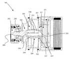
- FIG. 1depicts a cross-sectional view of an embodiment of a center conductor engagement member disposed within a first embodiment of a coaxial cable connector;
- FIG. 2depicts a cross-sectional view of an embodiment of a center conductor engagement member disposed within a second embodiment of a coaxial cable connector;
- FIG. 3Adepicts an exploded view of the first embodiment of the coaxial cable connector having an embodiment of the center conductor engagement member
- FIG. 3Bdepicts an exploded view of the second embodiments of the coaxial cable connector having an embodiment of the center conductor engagement member
- FIG. 4Adepicts a perspective view of a first embodiment of a coaxial cable
- FIG. 4Bdepicts a perspective view of a second embodiment of the coaxial cable
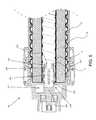
- FIG. 5depicts a cross-sectional view of an embodiment of the center conductor engagement member disposed within an embodiment of the connector, in a second, closed position;
- FIG. 6depicts a graph displaying data and test results regarding PIM performance of the first and second embodiments of the coaxial cable connector including an embodiment of the center conductor engagement member;
- FIG. 7depicts a graph displaying data and test results regarding return loss performance of the first and second embodiments of the coaxial cable connector including an embodiment of the center conductor engagement member.
- FIG. 1depicts an embodiment of a center conductor engagement member 200 disposed within a coaxial cable connector 100 , wherein the center conductor engagement member 200 is configured to mate, accept, engage, seize, etc, a hollow center conductor 18 of a coaxial cable 10 .
- Embodiments of the center conductor engagement member 200may be a conductive element that may extend or carry an electrical current and/or signal from a first point to a second point.
- the center conductor engagement member 200may be a contact, a terminal, a pin, a conductor, an electrical contact, a curved contact, a bended contact, an angled contact, and the like.
- the center conductor engagement member 200may be a contact for a 50 Ohm DIN female, 15 ⁇ 8′′. In another embodiment, the center conductor engagement member 200 may be a contact for a 50 Ohm DIN male, 15 ⁇ 8′′.
- Embodiments of the center conductor engagement member 200may include a first end 201 , a second end 202 , an inner surface 203 , and an outer surface 204 .
- Embodiments of the center conductor engagement member 200may further include a resilient contact region 240 proximate or otherwise near the first end 201 , an external contact interface 260 proximate or otherwise near the second end 202 , and a body portion 230 integrally connecting the resilient contact region 240 and the external contact interface 260 .
- the external contact interface 260may be a socket, a female contact, a male pin, or other physical device for establishing a physical and electrical connection with another coaxial cable connection, a splice connector, electronic device, and the like, and may be slotted.
- embodiments of the second end 202may not include an external conductive interface 260 that can operate as a socket, but rather the second end 202 may include a pin-like end for use with a male type connector, as shown in FIG. 2 .
- embodiments of the center conductor engagement member 200should be formed of conductive materials; however, one or more of the components comprising the center conductor engagement member 200 may not be conductive, such as an insert 250 , as described in greater detail infra.
- connector 100which may house the center conductor engagement member 200 , may be a straight connector, a right angle connector, an angled connector, an elbow connector, a DIN male or DIN female connector, or any complimentary connector that may receive a center conductor 18 of a coaxial cable.
- connector 100may be a coaxial cable connector used for terminating coaxial cable, such as 50 Ohm cable.
- Further embodiments of connector 100may receive a center conductor 18 of a coaxial cable 10 , wherein the coaxial cable 10 includes a spiral, corrugated, annular ribbed, smooth wall, or otherwise exposed outer conductor 14 .
- embodiments of connector 100can be a compression connector configured to be axially compressed (via an axial compression tool) into a compressed position of engagement with the cable 10 .
- Embodiments of connector 100may include a coupling member (not shown), a connector body 20 , an insulator 50 , a clamp 70 , a flanged bushing 80 , and an annular seal 90 .
- the connector body 20may comprise one, single component, or may be comprised of more than one component.
- the connector body 20may house the center conductor engagement member 200 , as well as the clamp 70 , the annular seal 90 , the flanged bushing 80 , the insulator 50 , and a coupling portion 30 .
- Embodiments of the clamp 70may be configured to clamp and/or seize the cable 10 , including the outer conductor 14 and/or the cable jacket 12 , as the connector 100 is initially attached to a prepared end of the cable 10 .
- Embodiments of the annular seal 90may be configured to compressibly deform upon axial compression to form an annular seal at a back end of the connector 100 .
- Embodiments of the insulator 50may electrically isolate the center conductor engagement member 200 and the outer conductor 14 and any component in conductive communication with the outer conductor 14 .
- the insulator 50which may be press fit within the connector body 20 may retain the center conductor engagement member 200 within the connector 100 .
- Embodiments of the coupling portion 30may be configured to physically mate or threadably engage a port, such an equipment port on a cell tower or other broadband equipment, or another coaxial cable connector.
- the coupling portion 30may include a threaded exterior surface, such as shown in FIG. 3A , or may include a rotatable coupler that may include a threaded inner surface, such as shown in FIG. 3B .
- a threaded exterior surfacesuch as shown in FIG. 3A
- a rotatable couplermay include a threaded inner surface, such as shown in FIG. 3B .
- the connector 100may also be provided to a user in a preassembled configuration to ease handling and installation during use. Two connectors, such as connector 100 may be utilized to create a jumper that may be packaged and sold to a consumer.
- a jumpermay be a coaxial cable 10 having a connector, such as connector 100 , operably affixed at one end of the cable 10 where the cable 10 has been prepared, and another connector, such as connector 100 , operably affixed at the other prepared end of the cable 10 .
- Operably affixed to a prepared end of a cable 10 with respect to a jumperincludes both an uncompressed/open position and a compressed/closed position of the connector while affixed to the cable.
- embodiments of a jumpermay include a first connector including components/features described in association with connector 100 , and a second connector that may also include the components/features as described in association with connector 100 , wherein the first connector is operably affixed to a first end of a coaxial cable 10 , and the second connector is operably affixed to a second end of the coaxial cable 10 .
- embodiments of a jumpermay include other components, such as one or more signal boosters, molded repeaters, and the like.
- the coaxial cable 10may be securely attached to a coaxial cable connector.
- the coaxial cable 10may include a center conductor 18 , such as a strand of conductive metallic material, surrounded by an interior dielectric 16 ; the interior dielectric 16 may possibly be surrounded by an outer conductor 14 ; the outer conductor 14 is surrounded by a protective outer jacket 12 , wherein the protective outer jacket 12 has dielectric properties and serves as an insulator.
- the center conductor 18may be hollow or tubular, such as a standard tubular center conductor associated with a standard 50 Ohm cable. Embodiments of the center conductor 18 may be smooth walled, or may have multiple corrugations.
- the outer conductor 14may extend a grounding path providing an electromagnetic shield about the center conductor 18 of the coaxial cable 10 .
- the outer conductor 14may be a rigid or semi-rigid outer conductor of the coaxial cable 10 formed of conductive metallic material, and may be corrugated, or otherwise grooved, or smooth walled.
- the outer conductor 14may be smooth walled, annularly ribbed, spiral corrugated, or helical corrugated.
- the coaxial cable 10may be prepared by removing a portion of the protective outer jacket 12 so that a length of the outer conductor 14 may be exposed, and then coring out a portion of the dielectric 16 to create a cavity 15 or space between the outer conductor 14 (and potentially the jacket 12 ), and the center conductor 18 .
- the protective outer jacket 12can physically protect the various components of the coaxial cable 10 from damage that may result from exposure to dirt or moisture, and from corrosion.
- the protective outer jacket 12may serve in some measure to secure the various components of the coaxial cable 10 in a contained cable design that protects the cable 10 from damage related to movement during cable installation.
- the outer conductor 14can be comprised of conductive materials suitable for carrying electromagnetic signals and/or providing an electrical ground connection or electrical path connection.
- the outer conductor layer 14may be employed to screen unwanted noise.
- the dielectric 16may be comprised of materials suitable for electrical insulation.
- the protective outer jacket 12may also be comprised of materials suitable for electrical insulation. It should be noted that the various materials of which all the various components of the coaxial cable 10 should have some degree of elasticity allowing the cable 10 to flex or bend in accordance with traditional broadband communications standards, installation methods and/or equipment. It should further be recognized that the radial thickness of the coaxial cable 10 , protective outer jacket 12 , outer conductor 14 , interior dielectric 16 , and/or center conductor 18 may vary based upon generally recognized parameters corresponding to broadband communication standards and/or equipment.
- embodiments of a center conductor engagement member 200may include a resilient contact region 240 proximate the first end 201 , the resilient contact region 240 configured to be compressed when inserted into a hollow center conductor 18 .
- Embodiments of the resilient contact region 240may include a first end 241 , a second end 242 , an inner surface 243 , and an outer surface 244 .
- the resilient contact region 240may be slotted to facilitate compression and/or deflection when surrounded by the center conductor 18 in a second, closed position.
- a slotted configuration of the resilient contact regionmay be effectuated by the presence of one or more axial through-slots 246 .
- Embodiments of the resilient contact region 240 having one or more axial slots 246may include one or more resilient contact finger 245 .
- embodiments of the center conductor engagement member 200may include a plurality of resilient contact fingers 245 proximate the first end 201 .
- Those having skill in the artshould appreciate that various slotted configurations may be employed to facilitate compression and/or deflection of the resilient contact fingers 245 .
- the amount of slots 246 , the length of the slots 246 , and width of the axial slots 246may be increased or decreased to increase or decrease the number and width of contact fingers 245 , respectively, which can have an impact on the deflection, stiffness, tunability, machinability (e.g.
- one or more slots 246may begin proximate the first end 241 of the resilient contact region 240 , but may not extend completely across the resilient contact region 240 to the second end 242 , while one or more slots 246 may begin from the second end 242 and may not extend completely across to the first end 241 ; this arrangement may alternate around the resilient contact region 240 .
- the resilient contact fingers 245may extend from a body 230 of the center conductor engagement member 200 .
- Embodiments of the resilient contact fingers 245in particular, the second end 242 of the resilient contact region 240 may be structurally integral with the body portion 230 .
- the second end 242 of the resilient contact regionmay be retained, secured, captured, etc., by the body 230 of the center conductor engagement member 200 .
- the plurality of resilient contact fingers 245may arc from the body 230 of the center conductor engagement member 200 until retained by an insert 250 .
- Embodiments of the resilient contact region 240may be curvilinear or substantially curvilinear from the first end 241 to the second end 242 .
- Embodiments of the resilient contact region 240may also be continuously curvilinear or continuously substantially curvilinear from the second end 242 proximate the body portion 230 to an internal annular protrusion 247 .
- embodiments of the resilient contact region 240may have a slotted oblong-like or elliptical-like shape, wherein a largest radial outer diameter of the resilient contact region 240 may occur at the vertex of the curve of the resilient contact region 240 .
- the substantially arced, curved, curvilinear, etc., shape of the resilient contact region 240 (and each of the plurality of resilient contact fingers 245 )may facilitate compression and/or deflection of the resilient contact region 240 , when the center conductor 18 is in the second, closed position.
- the substantially arced or curved resilient contact region 240may also assist the initial physical mating and timing of the mating of the center conductor 18 and resilient contact region 240 because of the gradual increase in radial diameter of the resilient contact region 240 .
- the distal end of the resilient contact fingers 245may include an internal annular protrusion 247 , wherein the distal end of the resilient contact fingers 245 can coincide with the first end 241 of the resilient contact region 240 ; an annular groove 249 may be located on the outer surface 203 proximate the location of the internal annular protrusion 247 .
- Embodiments of the internal annular protrusion 247may be a portion at the end of each resilient contact finger 245 that extends or protrudes a distance from the inner surface 203 , 243 towards a central axis 5 of the center conductor engagement member 200 .
- the internal annular protrusion 247may be configured to cooperate with an annular groove 257 of the insert 250 .
- the internal annular protrusion 247may snap into the groove 257 of the insert 250 to secure, retain, capture, etc., the first end 241 of the resilient contact region 240 of the center conductor engagement member 200 .
- the resilient contact region 240 of the center conductor engagement member 200may be engageable with the insert 250 ; the first end 241 of the resilient contact region may be securably retained within the annular groove 257 of the insert 250 , while the second 242 may be integrally retained by the body portion 230 .
- embodiments of the center conductor engagement member 200may include an insert 250 configured to retain or capture a first end 241 of the resilient contact region 240 .
- Embodiments of the insert 250may have a first end 251 and a second end 252 , and may be a generally annular member having a generally axial opening therethrough.
- embodiments of the insert 250may include an annular groove 257 configured to accept an internal annular protrusion 247 on the resilient contact finger 245 .
- the annular groove 257may be sized and dimensioned to receive the internal annular protrusion 247 of the contact finger 245 , and may be located between the first end 251 and the second end 252 .
- the wall of the annular groove 257 proximate or otherwise near the second end 252may be raised or extend radially outward slightly more than the wall of the annular groove 257 proximate or otherwise near the first end 251 of the insert 250 for retention purposes.
- Embodiments of the insert 250may be conductive, for example, comprised of a metal or a combination of metal, or embodiments of the insert 250 may be non-conductive, for example, comprised of a rubber or plastic, for cost control.
- an elastomeric band or rubber bandmay be placed within the annular groove 257 of the insert 250 to adjust the stiffness of the resilient contact region 240 .
- Embodiments of the insert 250may be comprised of elastic rubber material(s) instead of metal or plastic to reduce the stiffness of the resilient contact region 240 .
- Embodiments of the annular groove 257 of the insert 250may prevent movement of the resilient contact fingers 245 in an axial and/or radial direction that results in less than adequate return contact force against the inner surface of the hollow center conductor 18 , when the resilient contact region 240 is compressed as the hollow center conductor 18 passes over the resilient contact region 240 .
- the center conductoris configured to mate with the center conductor engagement member 200 , as shown in FIG. 1 . Continued advancement of the cable 10 within the connector 100 mates the center conductor 18 and the center conductor engagement member 200 .
- the resilient contact region 240 of the center conductor engagement member 200enters the hollow, tubular opening of the center conductor 18 . Because the largest outer diameter of the resilient contact region 240 may be slightly larger than the inner diameter of the hollow opening of the center conductor 18 , the center conductor 18 can exert a compressive force onto the resilient contact region 240 to axially and/or radially compress the resilient contact fingers 245 . Thus, the resilient contact fingers 245 may slightly move or flatten (e.g.
- the insert 250may prevent movement of the resilient contact fingers 245 that results in a less than adequate return contact force against the inner surface of the hollow center conductor 18 .
- the insert 250may prevent, or hinder over-compression, or excess deflection of the resilient contact fingers 245 such that cantilever-type deflection of the resilient contact fingers 245 is greatly minimized to ensure stiff, firm physical contact against the inner surface of the center conductor 18 , as shown in FIG. 5 .
- only a slight deflection of the resilient contact fingers 245is achieved because of the insert 250 operably attached to the first end 241 of the resilient contact region 240 , wherein only a slight deflection can ensure a firm return force exerted by the deflected resilient contact fingers 245 against the center conductor 18 in the opposite direction of the compressive force exerted by the center conductor 18 against the resilient contact region 240 .
- the insert 250 operably attached to the resilient contact region 240can provide for stiffness of the resilient contact fingers 245 while also ensuring adequate contact force with the hollow center conductor 18 .
- the resilient contact region 240 of the center conductor engagement member 200may be secured, retained, retainably secured, securably retained, captured, and the like, at both the first end 241 and the second 242 .
- the center conductor engagement member 200may then make good electrical contact on a large diameter range.
- FIG. 6discloses a chart 900 showing the results of PIM testing performed on the coaxial cable 10 that was terminated using the example compression connector 100 having a center conductor engagement member 200 .
- the particular test usedis known to those having skill in the requisite art as the International Electrotechnical Commission (IEC) Rotational Test.
- the PIM testing that produced the results in the chartwas also performed under dynamic conditions with impulses and vibrations applied to the example compression connector 100 during the testing.
- the PIM levels of the example compression connector, 100were measured on signals F1 UP and F2 DOWN to vary significantly less across frequencies 1870-1910 MHz. Further, the PIM levels of the example compression connector 100 remained well below the minimum acceptable industry standard of ⁇ 155 dBc.
- F1 UPachieved an intermodulation (IM) level of ⁇ 158.2 dBc at 1910 MHz
- F2 DOWNachieved an intermodulation (IM) level of ⁇ 159.7 dBc at 1910 MHz.
- IMintermodulation
- Compression connectors having PIM levels above this minimum acceptable standard of ⁇ 155 dBcresult in interfering RF signals that disrupt communication between sensitive receiver and transmitter equipment on the tower and lower-powered cellular devices in 4G systems.
- the relatively low PIM levels achieved using the example compression connector 100surpass the minimum acceptable level of ⁇ 155 dBc, thus reducing these interfering RF signals.
- the example field-installable compression connector 100 having a center conductor engagement member 200enables coaxial cable technicians to perform terminations of coaxial cable in the field that have sufficiently low levels of PIM to enable reliable 4G wireless communication.
- the example field-installable compression connector 100 having a center conductor engagement member 200exhibits impedance matching and PIM characteristics that match or exceed the corresponding characteristics of less convenient factory-installed soldered or welded connectors on pre-fabricated jumper cables.
- embodiments of connector 100may be a compression connector, wherein the compression connector achieves an intermodulation level below ⁇ 155 dBc over a frequency of 1870 MHz to 1910 MHz.
- FIG. 7discloses a chart 901 , corresponding graphical depictions, and associated data showing the results of “return loss” testing and impedance testing performed on the coaxial cable 10 that was terminated using the example compression connector 100 having a center conductor engagement member 200 .
- Return loss as shown in FIG. 7is expressed in ⁇ dB and reflects the ratio of the power of the reflected signal vs. the power of the incident signal. Thus, return loss, as measured, indicates how perfectly or imperfectly the coaxial cable line is terminated.
- the particular testwas conducted according to the standards set by the International Electrotechnical Commission (IEC) and known to those having ordinary skill in the requisite art.
- IECInternational Electrotechnical Commission
- Window 1displays a graph of the measured return loss over frequencies ranging from 14.925 MHz to 3,000 GHz. Window 1 also discloses a graduated limit 400 that graduates depending on a frequency range. The return loss at a specific frequency should not be less than the graduated limit 400 set for the frequency range. As disclosed in FIG. 7 , the chart lists four markers (4, 1, 2, 3—left to right) that denote the measured ratio of the return loss at a specific frequency. As depicted in FIG.
- Compression connectors having return loss greater than the graduated limits associated with specific frequency ranges indicated in FIG. 7result in interfering RF signals that disrupt communication between sensitive receiver and transmitter equipment; for example the connectors on cell towers and lower-powered cellular devices in 4G and 5G systems.
- the return loss measurements achieved using the example compression connector 100are well below the graduated limits associated with specific frequency ranges indicated in FIG. 7 , thus reducing these interfering RF signals.
- the example field-installable compression connector 100enables coaxial cable technicians to perform terminations of coaxial cable in the field that have advantageous ratios of return loss to enable reliable 4G and 5G wireless communication.
- the example field-installable compression connector 100exhibits return loss characteristics that match or exceed the corresponding characteristics of less convenient factory-installed soldered or welded connectors on pre-fabricated jumper cables.
- embodiments of connector 100may be a compression connector, wherein the compression connector achieves return loss ratios below acceptable levels of return loss set by the graduated limits associated with specific frequency ranges indicated in FIG. 7 .
- Window 2graphically depicts an impedance plot showing deviation of impedance.
- the two flag-like designatorsmark the limits of the gate and are associated with the condition of the test signal as it particularly passed through the tested embodiment of the connector 100 .
- the deviation of the impedance within the gate sectionis minimal, as shown by the fairly flat deviation line running with only marginal variance above and below the zero-point (0.00).
- This minimal deviation depicted in Window 2 of FIG. 8indicates that the performance of the connector 100 is not significantly impaired or burdened by substantial impedance problems, even while the signal travels through the connector along a right-angle path.
- the data and graphical depictions of the charts shown in FIG. 7work to validate the functional performance of the connector 100 , in having minimal impedance deviation, acceptable return loss levels, and minimized signal impact associated with passive intermodulation.
- a method of engaging a center conductor 18 of a coaxial cable 10may include the steps of disposing a center conductor engagement member 200 within a coaxial cable connector 100 , wherein the center conductor engagement member 200 includes a resilient contact region 240 having a first end 241 and a second end 242 , the resilient contact region 240 being substantially curvilinear from the first end 241 to the second end 242 , wherein the second end 242 of the resilient contact region 240 is secured by a body portion 230 , and an insert 250 engageable with the second end 242 of the resilient contact region 240 to retain the second end 242 of the resilient contact region 240 , and mating a center conductor 18 of a coaxial cable 10 with the center conductor engagement member 200 , wherein the center conductor engagement member 200 is configured to be inserted within the center conductor 18 .
Landscapes
- Coupling Device And Connection With Printed Circuit (AREA)
Abstract
Description
Claims (19)
Priority Applications (2)
| Application Number | Priority Date | Filing Date | Title |
|---|---|---|---|
| US13/738,363US9099825B2 (en) | 2012-01-12 | 2013-01-10 | Center conductor engagement mechanism |
| PCT/US2013/021147WO2013106650A1 (en) | 2012-01-12 | 2013-01-11 | Center conductor engagement mechanism |
Applications Claiming Priority (2)
| Application Number | Priority Date | Filing Date | Title |
|---|---|---|---|
| US201261585871P | 2012-01-12 | 2012-01-12 | |
| US13/738,363US9099825B2 (en) | 2012-01-12 | 2013-01-10 | Center conductor engagement mechanism |
Publications (2)
| Publication Number | Publication Date |
|---|---|
| US20130183856A1 US20130183856A1 (en) | 2013-07-18 |
| US9099825B2true US9099825B2 (en) | 2015-08-04 |
Family
ID=48780276
Family Applications (1)
| Application Number | Title | Priority Date | Filing Date |
|---|---|---|---|
| US13/738,363Active2033-06-09US9099825B2 (en) | 2012-01-12 | 2013-01-10 | Center conductor engagement mechanism |
Country Status (3)
| Country | Link |
|---|---|
| US (1) | US9099825B2 (en) |
| TW (1) | TW201336191A (en) |
| WO (1) | WO2013106650A1 (en) |
Cited By (3)
| Publication number | Priority date | Publication date | Assignee | Title |
|---|---|---|---|---|
| US20160218470A1 (en)* | 2015-01-28 | 2016-07-28 | Tyco Electronics (Shanghai) Co. Ltd. | Terminal assembly with cable and connector assembly |
| US11121502B2 (en)* | 2016-09-23 | 2021-09-14 | Apple Inc. | Magnetic connectors |
| US11217948B2 (en)* | 2015-06-10 | 2022-01-04 | Ppc Broadband, Inc. | Connector for engaging an outer conductor of a coaxial cable |
Families Citing this family (3)
| Publication number | Priority date | Publication date | Assignee | Title |
|---|---|---|---|---|
| GB201418486D0 (en)* | 2014-10-17 | 2014-12-03 | Creo Medical Ltd | Cable for conveying radiofrequency and/or microwave frequency energy to an electrosurgical instrument |
| JP7348024B2 (en)* | 2019-10-24 | 2023-09-20 | 日本航空電子工業株式会社 | Connector and connection method |
| TWI851014B (en)* | 2023-02-09 | 2024-08-01 | 朋程科技股份有限公司 | Power semiconductor packaging signal connection element and semiconductor module |
Citations (135)
| Publication number | Priority date | Publication date | Assignee | Title |
|---|---|---|---|---|
| GB1203775A (en) | 1966-11-09 | 1970-09-03 | Dunkel Otto Gmbh | Improvements relating to electric plug and socket contacts |
| US3764959A (en) | 1972-07-18 | 1973-10-09 | Astrolab | Universal coaxial cable connector |
| US3910673A (en) | 1973-09-18 | 1975-10-07 | Us Energy | Coaxial cable connectors |
| US4531805A (en) | 1984-04-03 | 1985-07-30 | Allied Corporation | Electrical connector assembly having means for EMI shielding |
| US4579415A (en) | 1984-04-23 | 1986-04-01 | Brunt Michael K Van | Grounding of shielded cables in a plug and receptacle electrical connector |
| US4676577A (en) | 1985-03-27 | 1987-06-30 | John Mezzalingua Associates, Inc. | Connector for coaxial cable |
| US4808128A (en) | 1984-04-02 | 1989-02-28 | Amphenol Corporation | Electrical connector assembly having means for EMI shielding |
| US4952174A (en) | 1989-05-15 | 1990-08-28 | Raychem Corporation | Coaxial cable connector |
| US5137470A (en) | 1991-06-04 | 1992-08-11 | Andrew Corporation | Connector for coaxial cable having a helically corrugated inner conductor |
| US5167533A (en) | 1992-01-08 | 1992-12-01 | Andrew Corporation | Connector for coaxial cable having hollow inner conductors |
| US5199894A (en) | 1990-12-14 | 1993-04-06 | Kalny Lou E | Self-locking connector |
| US5322454A (en) | 1992-10-29 | 1994-06-21 | Specialty Connector Company, Inc. | Connector for helically corrugated conduit |
| DE4344328C1 (en) | 1993-12-23 | 1995-01-12 | Spinner Gmbh Elektrotech | Plug connector for coaxial cables having a corrugated outer conductor |
| US5393244A (en) | 1994-01-25 | 1995-02-28 | John Mezzalingua Assoc. Inc. | Twist-on coaxial cable end connector with internal post |
| US5397243A (en) | 1993-09-03 | 1995-03-14 | Macmurdo, Sr.; Michael | Electrical cord protection wrap and plug cover |
| US5435745A (en) | 1994-05-31 | 1995-07-25 | Andrew Corporation | Connector for coaxial cable having corrugated outer conductor |
| US5518420A (en)* | 1993-06-01 | 1996-05-21 | Spinner Gmbh Elektrotechnische Fabrik | Electrical connector for a corrugated coaxial cable |
| US5620339A (en) | 1992-02-14 | 1997-04-15 | Itt Industries Ltd. | Electrical connectors |
| US5720630A (en) | 1993-09-13 | 1998-02-24 | Labinal Components And Systems, Inc. | Electrical connector |
| US5766037A (en) | 1996-10-11 | 1998-06-16 | Radio Frequency Systems, Inc. | Connector for a radio frequency cable |
| US5863220A (en) | 1996-11-12 | 1999-01-26 | Holliday; Randall A. | End connector fitting with crimping device |
| US5938474A (en) | 1997-12-10 | 1999-08-17 | Radio Frequency Systems, Inc. | Connector assembly for a coaxial cable |
| US5984723A (en) | 1996-09-14 | 1999-11-16 | Spinner Gmbh Elektrtechnische Fabrik | Connector for coaxial cable |
| US6019636A (en) | 1998-10-20 | 2000-02-01 | Eagle Comtronics, Inc. | Coaxial cable connector |
| US6019519A (en) | 1997-07-31 | 2000-02-01 | The Whitaker Corporation | Floating optical connector body and an optical connector |
| US6102738A (en) | 1997-08-05 | 2000-08-15 | Thomas & Betts International, Inc. | Hardline CATV power connector |
| US6109964A (en) | 1998-04-06 | 2000-08-29 | Andrew Corporation | One piece connector for a coaxial cable with an annularly corrugated outer conductor |
| US6123567A (en) | 1996-05-15 | 2000-09-26 | Centerpin Technology, Inc. | Coaxial cable connector |
| US6133532A (en) | 1998-02-17 | 2000-10-17 | Teracom Components Ab | Contact device |
| US6183298B1 (en) | 1998-10-13 | 2001-02-06 | Gilbert Engineering Co., Inc. | Connector for coaxial cable with friction locking arrangement |
| US6203360B1 (en) | 1999-02-18 | 2001-03-20 | Harting Kgaa | Conductor-connecting element for connecting electrical conductors to insulation-displacement contacts |
| US6206579B1 (en) | 1998-10-29 | 2001-03-27 | Amphenol Corporation | Arrangement for integrating a rectangular fiber optic connector into a cylindrical connector |
| US6264374B1 (en) | 1998-09-09 | 2001-07-24 | Amphenol Corporation | Arrangement for integrating a rectangular fiber optic connector into a cylindrical connector |
| US6267621B1 (en) | 1998-10-08 | 2001-07-31 | Spinner Gmbh Elektrotechnische Fabrik | Connector for a coaxial cable with annularly corrugated outer cable conductor |
| US6272738B1 (en) | 2000-04-05 | 2001-08-14 | Randall A. Holliday | Hand operated press for installing cable connectors |
| US6309251B1 (en) | 2000-06-01 | 2001-10-30 | Antronix, Inc. | Auto-seizing coaxial cable port for an electrical device |
| US6331123B1 (en) | 2000-11-20 | 2001-12-18 | Thomas & Betts International, Inc. | Connector for hard-line coaxial cable |
| US6386915B1 (en) | 2000-11-14 | 2002-05-14 | Radio Frequency Systems, Inc. | One step connector |
| US6471545B1 (en) | 1993-05-14 | 2002-10-29 | The Whitaker Corporation | Coaxial connector for coaxial cable having a corrugated outer conductor |
| US6478618B2 (en) | 2001-04-06 | 2002-11-12 | Shen-Chia Wong | High retention coaxial connector |
| US6494743B1 (en) | 1999-07-02 | 2002-12-17 | General Dynamics Information Systems, Inc. | Impedance-controlled connector |
| US6569565B2 (en) | 2000-03-16 | 2003-05-27 | Alcatel | Method of connecting plates of an electrode to a terminal of a storage cell, and the resulting cell |
| US6607398B2 (en) | 2000-04-17 | 2003-08-19 | Corning Gilbert Incorporated | Connector for a coaxial cable with corrugated outer conductor |
| US6733336B1 (en) | 2003-04-03 | 2004-05-11 | John Mezzalingua Associates, Inc. | Compression-type hard-line connector |
| KR200351496Y1 (en) | 2004-02-20 | 2004-05-24 | 조영민 | Wire cutting tool having open-gap support function |
| US6840803B2 (en) | 2003-02-13 | 2005-01-11 | Andrew Corporation | Crimp connector for corrugated cable |
| WO2005004290A1 (en) | 2003-07-04 | 2005-01-13 | Corning Cabelcon A/S | Coaxial connector |
| US6860761B2 (en) | 2003-01-13 | 2005-03-01 | Andrew Corporation | Right angle coaxial connector |
| US6878049B2 (en) | 2002-11-26 | 2005-04-12 | Dynabrade, Inc. | Random orbital sander |
| US20050079761A1 (en) | 2003-10-14 | 2005-04-14 | Thomas & Betts International, Inc. | Tooless coaxial connector |
| US6884115B2 (en) | 2002-05-31 | 2005-04-26 | Thomas & Betts International, Inc. | Connector for hard-line coaxial cable |
| US6884113B1 (en) | 2003-10-15 | 2005-04-26 | John Mezzalingua Associates, Inc. | Apparatus for making permanent hardline connection |
| US6926555B2 (en)* | 2003-10-09 | 2005-08-09 | Radio Frequency Systems, Inc. | Tuned radio frequency coaxial connector |
| US6939169B2 (en) | 2003-07-28 | 2005-09-06 | Andrew Corporation | Axial compression electrical connector |
| US6955562B1 (en) | 2004-06-15 | 2005-10-18 | Corning Gilbert Inc. | Coaxial connector with center conductor seizure |
| US6976872B1 (en) | 2002-06-22 | 2005-12-20 | Spinner Gmbh | Coaxial connector |
| US7008264B2 (en) | 2004-01-29 | 2006-03-07 | Spinner Gmbh | Connector for coaxial cable with annularly corrugated outside conductor |
| US7021965B1 (en) | 2005-07-13 | 2006-04-04 | John Mezza Lingua Associates, Inc. | Coaxial cable compression connector |
| US7029326B2 (en) | 2004-07-16 | 2006-04-18 | John Mezzalingua Associates, Inc. | Compression connector for coaxial cable |
| US7029304B2 (en) | 2004-02-04 | 2006-04-18 | John Mezzalingua Associates, Inc. | Compression connector with integral coupler |
| US20060134979A1 (en) | 2004-12-20 | 2006-06-22 | Henningsen Jimmy C | Coaxial connector with back nut clamping ring |
| US7070447B1 (en) | 2005-10-27 | 2006-07-04 | John Mezzalingua Associates, Inc. | Compact compression connector for spiral corrugated coaxial cable |
| US7086897B2 (en) | 2004-11-18 | 2006-08-08 | John Mezzalingua Associates, Inc. | Compression connector and method of use |
| US20060199431A1 (en) | 2003-07-28 | 2006-09-07 | Andrew Corporation | Connector with Corrugated Cable Interface Insert |
| US7108547B2 (en) | 2004-06-10 | 2006-09-19 | Corning Gilbert Inc. | Hardline coaxial cable connector |
| US7112093B1 (en) | 2005-03-15 | 2006-09-26 | Holland Electronics, Llc | Postless coaxial compression connector |
| US7121883B1 (en) | 2005-06-06 | 2006-10-17 | John Mezzalingua Associates, Inc. | Coax connector having steering insulator |
| US7128603B2 (en) | 2002-05-08 | 2006-10-31 | Corning Gilbert Inc. | Sealed coaxial cable connector and related method |
| US20060246774A1 (en) | 2005-04-29 | 2006-11-02 | Buck Bruce D | Coaxial cable connector assembly, system, and method |
| US7131868B2 (en) | 2004-07-16 | 2006-11-07 | John Mezzalingua Associates, Inc. | Compression connector for coaxial cable |
| US7156696B1 (en) | 2006-07-19 | 2007-01-02 | John Mezzalingua Associates, Inc. | Connector for corrugated coaxial cable and method |
| US7156560B2 (en) | 2005-05-13 | 2007-01-02 | Itt Manufacturing Enterprises, Inc. | Optic fiber alignment retainer assembly |
| US7179121B1 (en)* | 2005-09-23 | 2007-02-20 | Corning Gilbert Inc. | Coaxial cable connector |
| US7189115B1 (en) | 2005-12-29 | 2007-03-13 | John Mezzalingua Associates, Inc. | Connector for spiral corrugated coaxial cable and method of use thereof |
| US7207838B2 (en) | 2004-12-30 | 2007-04-24 | See Sprl | Coaxial connectors |
| US20070149047A1 (en) | 2005-12-22 | 2007-06-28 | Spinner Gmbh | Coaxial Plug-Type Connector and Method for Mounting the Same |
| US7264502B2 (en) | 2005-03-15 | 2007-09-04 | Michael Holland | Postless coaxial compression connector |
| WO2007101435A1 (en) | 2006-03-06 | 2007-09-13 | Ppc Denmark | A resilient clamp and a method of making the resilient clamp |
| US7278854B1 (en) | 2006-11-10 | 2007-10-09 | Tyco Electronics Corporation | Multi-signal single pin connector |
| US20070270032A1 (en) | 2006-05-18 | 2007-11-22 | Kim Eriksen | Sleeve for securing a cable in a connector |
| US7303435B2 (en) | 2005-01-14 | 2007-12-04 | Corning Gilbert, Inc. | Coaxial cable connector with pop-out pin |
| US7309255B2 (en) | 2005-03-11 | 2007-12-18 | Thomas & Betts International, Inc. | Coaxial connector with a cable gripping feature |
| US20080003873A1 (en) | 2006-06-29 | 2008-01-03 | Henningsen Jimmy C | Coaxial connector and method |
| US7335059B2 (en) | 2006-03-08 | 2008-02-26 | Commscope, Inc. Of North Carolina | Coaxial connector including clamping ramps and associated method |
| US7347729B2 (en) | 2005-10-20 | 2008-03-25 | Thomas & Betts International, Inc. | Prepless coaxial cable connector |
| US7351101B1 (en) | 2006-08-17 | 2008-04-01 | John Mezzalingua Associates, Inc. | Compact compression connector for annular corrugated coaxial cable |
| US7357672B2 (en) | 2006-07-19 | 2008-04-15 | John Mezzalingua Associates, Inc. | Connector for coaxial cable and method |
| US7374455B2 (en)* | 2006-10-19 | 2008-05-20 | John Mezzalingua Associates, Inc. | Connector assembly for a cable having a radially facing conductive surface and method of operatively assembling the connector assembly |
| US20080254678A1 (en) | 2007-04-14 | 2008-10-16 | Jeremy Amidon | Tightening Indicator For Coaxial Cable Connector |
| US20080274643A1 (en) | 2007-05-02 | 2008-11-06 | Shawn Chawgo | Compression Connector For Coaxial Cable |
| US7458851B2 (en) | 2007-02-22 | 2008-12-02 | John Mezzalingua Associates, Inc. | Coaxial cable connector with independently actuated engagement of inner and outer conductors |
| US7458850B1 (en) | 2007-05-23 | 2008-12-02 | Corning Gilbert Inc. | Right-angled coaxial cable connector |
| US7488210B1 (en)* | 2008-03-19 | 2009-02-10 | Corning Gilbert Inc. | RF terminator |
| US7497729B1 (en) | 2008-01-09 | 2009-03-03 | Ezconn Corporation | Mini-coaxial cable connector |
| US7513722B2 (en) | 2003-12-30 | 2009-04-07 | Greenberg Surgical Technologies, Llc | Collet collar stop for a drill bit |
| US7527512B2 (en) | 2006-12-08 | 2009-05-05 | John Mezza Lingua Associates, Inc. | Cable connector expanding contact |
| US7566243B1 (en) | 2008-01-10 | 2009-07-28 | Sandmartin (Zhong Shan) Electronic Co., Ltd. | Cable connector |
| US20090197465A1 (en) | 2007-05-02 | 2009-08-06 | John Mezzalingua Associates, Inc. | Compression connector for coaxial cable with staggered seizure of outer and center conductor |
| US7588460B2 (en) | 2007-04-17 | 2009-09-15 | Thomas & Betts International, Inc. | Coaxial cable connector with gripping ferrule |
| US20090233482A1 (en) | 2007-05-02 | 2009-09-17 | Shawn Chawgo | Compression Connector For Coaxial Cable |
| US20090269979A1 (en) | 2006-12-08 | 2009-10-29 | Noah Montena | Cable connector expanding contact |
| US7632143B1 (en) | 2008-11-24 | 2009-12-15 | Andrew Llc | Connector with positive stop and compressible ring for coaxial cable and associated methods |
| US7635283B1 (en)* | 2008-11-24 | 2009-12-22 | Andrew Llc | Connector with retaining ring for coaxial cable and associated methods |
| US7637774B1 (en) | 2008-08-29 | 2009-12-29 | Commscope, Inc. Of North Carolina | Method for making coaxial cable connector components for multiple configurations and related devices |
| EP2190068A1 (en) | 2008-11-24 | 2010-05-26 | Andrew LLC | Connector with positive stop for coaxial cable and associated methods |
| US7806724B2 (en) | 2008-11-05 | 2010-10-05 | Andrew Llc | Coaxial connector for cable with a solid outer conductor |
| US20100261381A1 (en) | 2009-04-10 | 2010-10-14 | John Mezzalingua Associates, Inc. | Compression connector for coaxial cables |
| US20100261382A1 (en) | 2009-04-10 | 2010-10-14 | John Mezzalingua Associates, Inc. | Compression coaxial cable connector with center insulator seizing mechanism |
| US7819698B2 (en)* | 2007-08-22 | 2010-10-26 | Andrew Llc | Sealed inner conductor contact for coaxial cable connector |
| US20100273340A1 (en) | 2009-04-24 | 2010-10-28 | Jan Michael Clausen | Coaxial Connector For Corrugated Cable With Corrugated Sealing |
| US7824215B2 (en) | 2008-11-05 | 2010-11-02 | Andrew Llc | Axial compression coaxial connector with grip surfaces |
| US7857661B1 (en) | 2010-02-16 | 2010-12-28 | Andrew Llc | Coaxial cable connector having jacket gripping ferrule and associated methods |
| EP2219267B1 (en) | 2009-02-13 | 2011-01-12 | Alcatel Lucent | Manufacturing method for a connection between a coaxial cable and a coaxial connector and a coaxial cable with a terminating coaxial connector thereof |
| US20110009000A1 (en) | 2008-11-05 | 2011-01-13 | Andrew Llc | Shielded grip ring for coaxial connector |
| US20110008998A1 (en) | 2008-11-05 | 2011-01-13 | Andrew Llc | Interleaved Outer Conductor Shield Contact |
| US20110021074A1 (en) | 2008-11-05 | 2011-01-27 | Andrew Llc | Self Gauging Insertion Coupling Coaxial Connector |
| US7918687B2 (en) | 2008-11-05 | 2011-04-05 | Andrew Llc | Coaxial connector grip ring having an anti-rotation feature |
| US7927134B2 (en) | 2008-11-05 | 2011-04-19 | Andrew Llc | Coaxial connector for cable with a solid outer conductor |
| US7934954B1 (en)* | 2010-04-02 | 2011-05-03 | John Mezzalingua Associates, Inc. | Coaxial cable compression connectors |
| US20110263154A1 (en) | 2007-05-02 | 2011-10-27 | John Mezzalingua Associates, Inc. | Compression connector for coaxial cable |
| US8047870B2 (en) | 2009-01-09 | 2011-11-01 | Corning Gilbert Inc. | Coaxial connector for corrugated cable |
| US8052465B1 (en)* | 2011-02-18 | 2011-11-08 | John Mezzalingua Associates, Inc. | Cable connector expanding contact |
| US8136236B2 (en) | 2009-09-15 | 2012-03-20 | John Mezzalingua Associates, Inc. | Method for manufacturing a coaxial cable |
| US20120088381A1 (en) | 2010-10-08 | 2012-04-12 | John Mezzalingua Associates, Inc. | Connector contact for tubular center conductor |
| US20120088404A1 (en) | 2010-10-08 | 2012-04-12 | John Mezzalingua Associates, Inc. | Connector assembly for corrugated coaxial cable |
| US20120088407A1 (en) | 2010-10-08 | 2012-04-12 | John Mezzalingua Associates, Inc. | Connector assembly for corrugated coaxial cable |
| US20120088405A1 (en) | 2010-10-08 | 2012-04-12 | John Mezzalingua Associates, Inc. | Connector assembly for corrugated coaxial cable |
| US20120088406A1 (en) | 2010-10-08 | 2012-04-12 | John Mezzalingua Associates, Inc. | Connector assembly having deformable clamping surface |
| US20120102733A1 (en) | 2010-10-28 | 2012-05-03 | John Mezzalingua Associates, Inc. | Corrugated coaxial cable preparation |
| US20120214338A1 (en) | 2011-02-23 | 2012-08-23 | John Mezzalingua Associates, Inc. | Connector having co-cylindrical contact between a socket and a center conductor |
| US20120252265A1 (en) | 2011-03-31 | 2012-10-04 | John Mezzalingua Associates, Inc. | Connector assembly for corrugated coaxial cable |
| US8400318B2 (en)* | 2007-09-24 | 2013-03-19 | John Mezzalingua Associates, Inc. | Method for determining electrical power signal levels in a transmission system |
| US8419464B2 (en)* | 2008-11-17 | 2013-04-16 | Ppc Broadband, Inc. | Coaxial connector with integrated molded substrate and method of use thereof |
| US8747152B2 (en)* | 2012-11-09 | 2014-06-10 | Andrew Llc | RF isolated capacitively coupled connector |
| US8773255B2 (en)* | 2007-09-24 | 2014-07-08 | Ppc Broadband, Inc. | Status sensing and reporting interface |
- 2013
- 2013-01-10USUS13/738,363patent/US9099825B2/enactiveActive
- 2013-01-11TWTW102101111Apatent/TW201336191A/enunknown
- 2013-01-11WOPCT/US2013/021147patent/WO2013106650A1/enactiveApplication Filing
Patent Citations (153)
| Publication number | Priority date | Publication date | Assignee | Title |
|---|---|---|---|---|
| GB1203775A (en) | 1966-11-09 | 1970-09-03 | Dunkel Otto Gmbh | Improvements relating to electric plug and socket contacts |
| US3764959A (en) | 1972-07-18 | 1973-10-09 | Astrolab | Universal coaxial cable connector |
| US3910673A (en) | 1973-09-18 | 1975-10-07 | Us Energy | Coaxial cable connectors |
| US4808128A (en) | 1984-04-02 | 1989-02-28 | Amphenol Corporation | Electrical connector assembly having means for EMI shielding |
| US4531805A (en) | 1984-04-03 | 1985-07-30 | Allied Corporation | Electrical connector assembly having means for EMI shielding |
| US4579415A (en) | 1984-04-23 | 1986-04-01 | Brunt Michael K Van | Grounding of shielded cables in a plug and receptacle electrical connector |
| US4676577A (en) | 1985-03-27 | 1987-06-30 | John Mezzalingua Associates, Inc. | Connector for coaxial cable |
| US4952174A (en) | 1989-05-15 | 1990-08-28 | Raychem Corporation | Coaxial cable connector |
| US5199894A (en) | 1990-12-14 | 1993-04-06 | Kalny Lou E | Self-locking connector |
| US5137470A (en) | 1991-06-04 | 1992-08-11 | Andrew Corporation | Connector for coaxial cable having a helically corrugated inner conductor |
| US5167533A (en) | 1992-01-08 | 1992-12-01 | Andrew Corporation | Connector for coaxial cable having hollow inner conductors |
| US5620339A (en) | 1992-02-14 | 1997-04-15 | Itt Industries Ltd. | Electrical connectors |
| US5322454A (en) | 1992-10-29 | 1994-06-21 | Specialty Connector Company, Inc. | Connector for helically corrugated conduit |
| US6471545B1 (en) | 1993-05-14 | 2002-10-29 | The Whitaker Corporation | Coaxial connector for coaxial cable having a corrugated outer conductor |
| US5518420A (en)* | 1993-06-01 | 1996-05-21 | Spinner Gmbh Elektrotechnische Fabrik | Electrical connector for a corrugated coaxial cable |
| US5397243A (en) | 1993-09-03 | 1995-03-14 | Macmurdo, Sr.; Michael | Electrical cord protection wrap and plug cover |
| US5720630A (en) | 1993-09-13 | 1998-02-24 | Labinal Components And Systems, Inc. | Electrical connector |
| DE4344328C1 (en) | 1993-12-23 | 1995-01-12 | Spinner Gmbh Elektrotech | Plug connector for coaxial cables having a corrugated outer conductor |
| US5393244A (en) | 1994-01-25 | 1995-02-28 | John Mezzalingua Assoc. Inc. | Twist-on coaxial cable end connector with internal post |
| US5435745A (en) | 1994-05-31 | 1995-07-25 | Andrew Corporation | Connector for coaxial cable having corrugated outer conductor |
| US6123567A (en) | 1996-05-15 | 2000-09-26 | Centerpin Technology, Inc. | Coaxial cable connector |
| US6032358A (en) | 1996-09-14 | 2000-03-07 | Spinner Gmbh Elektrotechnische Fabrik | Connector for coaxial cable |
| US5984723A (en) | 1996-09-14 | 1999-11-16 | Spinner Gmbh Elektrtechnische Fabrik | Connector for coaxial cable |
| US5766037A (en) | 1996-10-11 | 1998-06-16 | Radio Frequency Systems, Inc. | Connector for a radio frequency cable |
| US5863220A (en) | 1996-11-12 | 1999-01-26 | Holliday; Randall A. | End connector fitting with crimping device |
| US6019519A (en) | 1997-07-31 | 2000-02-01 | The Whitaker Corporation | Floating optical connector body and an optical connector |
| US6102738A (en) | 1997-08-05 | 2000-08-15 | Thomas & Betts International, Inc. | Hardline CATV power connector |
| US5938474A (en) | 1997-12-10 | 1999-08-17 | Radio Frequency Systems, Inc. | Connector assembly for a coaxial cable |
| US6133532A (en) | 1998-02-17 | 2000-10-17 | Teracom Components Ab | Contact device |
| US6109964A (en) | 1998-04-06 | 2000-08-29 | Andrew Corporation | One piece connector for a coaxial cable with an annularly corrugated outer conductor |
| US6264374B1 (en) | 1998-09-09 | 2001-07-24 | Amphenol Corporation | Arrangement for integrating a rectangular fiber optic connector into a cylindrical connector |
| US6267621B1 (en) | 1998-10-08 | 2001-07-31 | Spinner Gmbh Elektrotechnische Fabrik | Connector for a coaxial cable with annularly corrugated outer cable conductor |
| US6183298B1 (en) | 1998-10-13 | 2001-02-06 | Gilbert Engineering Co., Inc. | Connector for coaxial cable with friction locking arrangement |
| US6019636A (en) | 1998-10-20 | 2000-02-01 | Eagle Comtronics, Inc. | Coaxial cable connector |
| US6206579B1 (en) | 1998-10-29 | 2001-03-27 | Amphenol Corporation | Arrangement for integrating a rectangular fiber optic connector into a cylindrical connector |
| US6203360B1 (en) | 1999-02-18 | 2001-03-20 | Harting Kgaa | Conductor-connecting element for connecting electrical conductors to insulation-displacement contacts |
| US6494743B1 (en) | 1999-07-02 | 2002-12-17 | General Dynamics Information Systems, Inc. | Impedance-controlled connector |
| US6569565B2 (en) | 2000-03-16 | 2003-05-27 | Alcatel | Method of connecting plates of an electrode to a terminal of a storage cell, and the resulting cell |
| US6272738B1 (en) | 2000-04-05 | 2001-08-14 | Randall A. Holliday | Hand operated press for installing cable connectors |
| US6607398B2 (en) | 2000-04-17 | 2003-08-19 | Corning Gilbert Incorporated | Connector for a coaxial cable with corrugated outer conductor |
| US6309251B1 (en) | 2000-06-01 | 2001-10-30 | Antronix, Inc. | Auto-seizing coaxial cable port for an electrical device |
| US6386915B1 (en) | 2000-11-14 | 2002-05-14 | Radio Frequency Systems, Inc. | One step connector |
| US6331123B1 (en) | 2000-11-20 | 2001-12-18 | Thomas & Betts International, Inc. | Connector for hard-line coaxial cable |
| US6478618B2 (en) | 2001-04-06 | 2002-11-12 | Shen-Chia Wong | High retention coaxial connector |
| US7128603B2 (en) | 2002-05-08 | 2006-10-31 | Corning Gilbert Inc. | Sealed coaxial cable connector and related method |
| US6884115B2 (en) | 2002-05-31 | 2005-04-26 | Thomas & Betts International, Inc. | Connector for hard-line coaxial cable |
| US6976872B1 (en) | 2002-06-22 | 2005-12-20 | Spinner Gmbh | Coaxial connector |
| US6878049B2 (en) | 2002-11-26 | 2005-04-12 | Dynabrade, Inc. | Random orbital sander |
| US6860761B2 (en) | 2003-01-13 | 2005-03-01 | Andrew Corporation | Right angle coaxial connector |
| US6840803B2 (en) | 2003-02-13 | 2005-01-11 | Andrew Corporation | Crimp connector for corrugated cable |
| US6733336B1 (en) | 2003-04-03 | 2004-05-11 | John Mezzalingua Associates, Inc. | Compression-type hard-line connector |
| WO2005004290A1 (en) | 2003-07-04 | 2005-01-13 | Corning Cabelcon A/S | Coaxial connector |
| US20060014427A1 (en) | 2003-07-28 | 2006-01-19 | Andrew Corporation | Axial compression electrical connector |
| US20060199431A1 (en) | 2003-07-28 | 2006-09-07 | Andrew Corporation | Connector with Corrugated Cable Interface Insert |
| US6939169B2 (en) | 2003-07-28 | 2005-09-06 | Andrew Corporation | Axial compression electrical connector |
| US7077699B2 (en) | 2003-07-28 | 2006-07-18 | Andrew Corporation | Axial compression electrical connector |
| US6926555B2 (en)* | 2003-10-09 | 2005-08-09 | Radio Frequency Systems, Inc. | Tuned radio frequency coaxial connector |
| US20050079761A1 (en) | 2003-10-14 | 2005-04-14 | Thomas & Betts International, Inc. | Tooless coaxial connector |
| US6884113B1 (en) | 2003-10-15 | 2005-04-26 | John Mezzalingua Associates, Inc. | Apparatus for making permanent hardline connection |
| US7513722B2 (en) | 2003-12-30 | 2009-04-07 | Greenberg Surgical Technologies, Llc | Collet collar stop for a drill bit |
| US7008264B2 (en) | 2004-01-29 | 2006-03-07 | Spinner Gmbh | Connector for coaxial cable with annularly corrugated outside conductor |
| US7029304B2 (en) | 2004-02-04 | 2006-04-18 | John Mezzalingua Associates, Inc. | Compression connector with integral coupler |
| US7163420B2 (en) | 2004-02-04 | 2007-01-16 | John Mezzalingua Assoicates, Inc. | Compression connector with integral coupler |
| KR200351496Y1 (en) | 2004-02-20 | 2004-05-24 | 조영민 | Wire cutting tool having open-gap support function |
| US7108547B2 (en) | 2004-06-10 | 2006-09-19 | Corning Gilbert Inc. | Hardline coaxial cable connector |
| US6955562B1 (en) | 2004-06-15 | 2005-10-18 | Corning Gilbert Inc. | Coaxial connector with center conductor seizure |
| US7104839B2 (en) | 2004-06-15 | 2006-09-12 | Corning Gilbert Inc. | Coaxial connector with center conductor seizure |
| US7029326B2 (en) | 2004-07-16 | 2006-04-18 | John Mezzalingua Associates, Inc. | Compression connector for coaxial cable |
| US7131868B2 (en) | 2004-07-16 | 2006-11-07 | John Mezzalingua Associates, Inc. | Compression connector for coaxial cable |
| US7086897B2 (en) | 2004-11-18 | 2006-08-08 | John Mezzalingua Associates, Inc. | Compression connector and method of use |
| US20060134979A1 (en) | 2004-12-20 | 2006-06-22 | Henningsen Jimmy C | Coaxial connector with back nut clamping ring |
| US7207838B2 (en) | 2004-12-30 | 2007-04-24 | See Sprl | Coaxial connectors |
| US7303435B2 (en) | 2005-01-14 | 2007-12-04 | Corning Gilbert, Inc. | Coaxial cable connector with pop-out pin |
| US7309255B2 (en) | 2005-03-11 | 2007-12-18 | Thomas & Betts International, Inc. | Coaxial connector with a cable gripping feature |
| US7112093B1 (en) | 2005-03-15 | 2006-09-26 | Holland Electronics, Llc | Postless coaxial compression connector |
| US7264502B2 (en) | 2005-03-15 | 2007-09-04 | Michael Holland | Postless coaxial compression connector |
| US20060246774A1 (en) | 2005-04-29 | 2006-11-02 | Buck Bruce D | Coaxial cable connector assembly, system, and method |
| US7156560B2 (en) | 2005-05-13 | 2007-01-02 | Itt Manufacturing Enterprises, Inc. | Optic fiber alignment retainer assembly |
| US7121883B1 (en) | 2005-06-06 | 2006-10-17 | John Mezzalingua Associates, Inc. | Coax connector having steering insulator |
| US7021965B1 (en) | 2005-07-13 | 2006-04-04 | John Mezza Lingua Associates, Inc. | Coaxial cable compression connector |
| US7179121B1 (en)* | 2005-09-23 | 2007-02-20 | Corning Gilbert Inc. | Coaxial cable connector |
| US7347729B2 (en) | 2005-10-20 | 2008-03-25 | Thomas & Betts International, Inc. | Prepless coaxial cable connector |
| US7070447B1 (en) | 2005-10-27 | 2006-07-04 | John Mezzalingua Associates, Inc. | Compact compression connector for spiral corrugated coaxial cable |
| US20070149047A1 (en) | 2005-12-22 | 2007-06-28 | Spinner Gmbh | Coaxial Plug-Type Connector and Method for Mounting the Same |
| US7189115B1 (en) | 2005-12-29 | 2007-03-13 | John Mezzalingua Associates, Inc. | Connector for spiral corrugated coaxial cable and method of use thereof |
| WO2007101435A1 (en) | 2006-03-06 | 2007-09-13 | Ppc Denmark | A resilient clamp and a method of making the resilient clamp |
| US7335059B2 (en) | 2006-03-08 | 2008-02-26 | Commscope, Inc. Of North Carolina | Coaxial connector including clamping ramps and associated method |
| EP1858123A2 (en) | 2006-05-15 | 2007-11-21 | Andrew Corporation | Connector with corrugated cable interface insert |
| US20070270032A1 (en) | 2006-05-18 | 2007-11-22 | Kim Eriksen | Sleeve for securing a cable in a connector |
| US20080003873A1 (en) | 2006-06-29 | 2008-01-03 | Henningsen Jimmy C | Coaxial connector and method |
| US7156696B1 (en) | 2006-07-19 | 2007-01-02 | John Mezzalingua Associates, Inc. | Connector for corrugated coaxial cable and method |
| US7357672B2 (en) | 2006-07-19 | 2008-04-15 | John Mezzalingua Associates, Inc. | Connector for coaxial cable and method |
| US7351101B1 (en) | 2006-08-17 | 2008-04-01 | John Mezzalingua Associates, Inc. | Compact compression connector for annular corrugated coaxial cable |
| US7374455B2 (en)* | 2006-10-19 | 2008-05-20 | John Mezzalingua Associates, Inc. | Connector assembly for a cable having a radially facing conductive surface and method of operatively assembling the connector assembly |
| US7278854B1 (en) | 2006-11-10 | 2007-10-09 | Tyco Electronics Corporation | Multi-signal single pin connector |
| US20090269979A1 (en) | 2006-12-08 | 2009-10-29 | Noah Montena | Cable connector expanding contact |
| US7527512B2 (en) | 2006-12-08 | 2009-05-05 | John Mezza Lingua Associates, Inc. | Cable connector expanding contact |
| US7458851B2 (en) | 2007-02-22 | 2008-12-02 | John Mezzalingua Associates, Inc. | Coaxial cable connector with independently actuated engagement of inner and outer conductors |
| US20080254678A1 (en) | 2007-04-14 | 2008-10-16 | Jeremy Amidon | Tightening Indicator For Coaxial Cable Connector |
| US7588460B2 (en) | 2007-04-17 | 2009-09-15 | Thomas & Betts International, Inc. | Coaxial cable connector with gripping ferrule |
| US20090197465A1 (en) | 2007-05-02 | 2009-08-06 | John Mezzalingua Associates, Inc. | Compression connector for coaxial cable with staggered seizure of outer and center conductor |
| US7993159B2 (en) | 2007-05-02 | 2011-08-09 | John Mezzalingua Associates, Inc. | Compression connector for coaxial cable |
| US20080274643A1 (en) | 2007-05-02 | 2008-11-06 | Shawn Chawgo | Compression Connector For Coaxial Cable |
| US20110263154A1 (en) | 2007-05-02 | 2011-10-27 | John Mezzalingua Associates, Inc. | Compression connector for coaxial cable |
| US8177583B2 (en) | 2007-05-02 | 2012-05-15 | John Mezzalingua Associates, Inc. | Compression connector for coaxial cable |
| US20090233482A1 (en) | 2007-05-02 | 2009-09-17 | Shawn Chawgo | Compression Connector For Coaxial Cable |
| US8007314B2 (en) | 2007-05-02 | 2011-08-30 | John Mezzalingua Associates, Inc. | Compression connector for coaxial cable |
| US8123557B2 (en) | 2007-05-02 | 2012-02-28 | John Mezzalingua Associates, Inc. | Compression connector for coaxial cable with staggered seizure of outer and center conductor |
| US7458850B1 (en) | 2007-05-23 | 2008-12-02 | Corning Gilbert Inc. | Right-angled coaxial cable connector |
| US7819698B2 (en)* | 2007-08-22 | 2010-10-26 | Andrew Llc | Sealed inner conductor contact for coaxial cable connector |
| US8400318B2 (en)* | 2007-09-24 | 2013-03-19 | John Mezzalingua Associates, Inc. | Method for determining electrical power signal levels in a transmission system |
| US8773255B2 (en)* | 2007-09-24 | 2014-07-08 | Ppc Broadband, Inc. | Status sensing and reporting interface |
| US7497729B1 (en) | 2008-01-09 | 2009-03-03 | Ezconn Corporation | Mini-coaxial cable connector |
| US7566243B1 (en) | 2008-01-10 | 2009-07-28 | Sandmartin (Zhong Shan) Electronic Co., Ltd. | Cable connector |
| US7488210B1 (en)* | 2008-03-19 | 2009-02-10 | Corning Gilbert Inc. | RF terminator |
| US7637774B1 (en) | 2008-08-29 | 2009-12-29 | Commscope, Inc. Of North Carolina | Method for making coaxial cable connector components for multiple configurations and related devices |
| US7806724B2 (en) | 2008-11-05 | 2010-10-05 | Andrew Llc | Coaxial connector for cable with a solid outer conductor |
| US7824215B2 (en) | 2008-11-05 | 2010-11-02 | Andrew Llc | Axial compression coaxial connector with grip surfaces |
| US7927134B2 (en) | 2008-11-05 | 2011-04-19 | Andrew Llc | Coaxial connector for cable with a solid outer conductor |
| US20110009000A1 (en) | 2008-11-05 | 2011-01-13 | Andrew Llc | Shielded grip ring for coaxial connector |
| US20110008998A1 (en) | 2008-11-05 | 2011-01-13 | Andrew Llc | Interleaved Outer Conductor Shield Contact |
| US20110021074A1 (en) | 2008-11-05 | 2011-01-27 | Andrew Llc | Self Gauging Insertion Coupling Coaxial Connector |
| US7918687B2 (en) | 2008-11-05 | 2011-04-05 | Andrew Llc | Coaxial connector grip ring having an anti-rotation feature |
| US8419464B2 (en)* | 2008-11-17 | 2013-04-16 | Ppc Broadband, Inc. | Coaxial connector with integrated molded substrate and method of use thereof |
| EP2190068A1 (en) | 2008-11-24 | 2010-05-26 | Andrew LLC | Connector with positive stop for coaxial cable and associated methods |
| US7635283B1 (en)* | 2008-11-24 | 2009-12-22 | Andrew Llc | Connector with retaining ring for coaxial cable and associated methods |
| US7632143B1 (en) | 2008-11-24 | 2009-12-15 | Andrew Llc | Connector with positive stop and compressible ring for coaxial cable and associated methods |
| US8047870B2 (en) | 2009-01-09 | 2011-11-01 | Corning Gilbert Inc. | Coaxial connector for corrugated cable |
| EP2219267B1 (en) | 2009-02-13 | 2011-01-12 | Alcatel Lucent | Manufacturing method for a connection between a coaxial cable and a coaxial connector and a coaxial cable with a terminating coaxial connector thereof |
| US20100261382A1 (en) | 2009-04-10 | 2010-10-14 | John Mezzalingua Associates, Inc. | Compression coaxial cable connector with center insulator seizing mechanism |
| US8038472B2 (en) | 2009-04-10 | 2011-10-18 | John Mezzalingua Associates, Inc. | Compression coaxial cable connector with center insulator seizing mechanism |
| US20100261381A1 (en) | 2009-04-10 | 2010-10-14 | John Mezzalingua Associates, Inc. | Compression connector for coaxial cables |
| US20100273340A1 (en) | 2009-04-24 | 2010-10-28 | Jan Michael Clausen | Coaxial Connector For Corrugated Cable With Corrugated Sealing |
| US8136236B2 (en) | 2009-09-15 | 2012-03-20 | John Mezzalingua Associates, Inc. | Method for manufacturing a coaxial cable |
| US7857661B1 (en) | 2010-02-16 | 2010-12-28 | Andrew Llc | Coaxial cable connector having jacket gripping ferrule and associated methods |
| US7934954B1 (en)* | 2010-04-02 | 2011-05-03 | John Mezzalingua Associates, Inc. | Coaxial cable compression connectors |
| US8388375B2 (en)* | 2010-04-02 | 2013-03-05 | John Mezzalingua Associates, Inc. | Coaxial cable compression connectors |
| US8602818B1 (en)* | 2010-04-02 | 2013-12-10 | John Mezzalingua Associates, LLC | Compression connector for cables |
| US8591253B1 (en)* | 2010-04-02 | 2013-11-26 | John Mezzalingua Associates, LLC | Cable compression connectors |
| US20110244722A1 (en)* | 2010-04-02 | 2011-10-06 | John Mezzalingua Associates, Inc. | Coaxial cable compression connectors |
| US20120088404A1 (en) | 2010-10-08 | 2012-04-12 | John Mezzalingua Associates, Inc. | Connector assembly for corrugated coaxial cable |
| US8298006B2 (en) | 2010-10-08 | 2012-10-30 | John Mezzalingua Associates, Inc. | Connector contact for tubular center conductor |
| US20120088407A1 (en) | 2010-10-08 | 2012-04-12 | John Mezzalingua Associates, Inc. | Connector assembly for corrugated coaxial cable |
| US20120088381A1 (en) | 2010-10-08 | 2012-04-12 | John Mezzalingua Associates, Inc. | Connector contact for tubular center conductor |
| US8435073B2 (en)* | 2010-10-08 | 2013-05-07 | John Mezzalingua Associates, LLC | Connector assembly for corrugated coaxial cable |
| US8439703B2 (en)* | 2010-10-08 | 2013-05-14 | John Mezzalingua Associates, LLC | Connector assembly for corrugated coaxial cable |
| US20120088406A1 (en) | 2010-10-08 | 2012-04-12 | John Mezzalingua Associates, Inc. | Connector assembly having deformable clamping surface |
| US20120088405A1 (en) | 2010-10-08 | 2012-04-12 | John Mezzalingua Associates, Inc. | Connector assembly for corrugated coaxial cable |
| US20120102733A1 (en) | 2010-10-28 | 2012-05-03 | John Mezzalingua Associates, Inc. | Corrugated coaxial cable preparation |
| US8052465B1 (en)* | 2011-02-18 | 2011-11-08 | John Mezzalingua Associates, Inc. | Cable connector expanding contact |
| US20120214338A1 (en) | 2011-02-23 | 2012-08-23 | John Mezzalingua Associates, Inc. | Connector having co-cylindrical contact between a socket and a center conductor |
| US20120252265A1 (en) | 2011-03-31 | 2012-10-04 | John Mezzalingua Associates, Inc. | Connector assembly for corrugated coaxial cable |
| US8747152B2 (en)* | 2012-11-09 | 2014-06-10 | Andrew Llc | RF isolated capacitively coupled connector |
Non-Patent Citations (1)
| Title |
|---|
| PCT/US2013/021147 Date of mailing: Mar. 13, 2013 International Search Report and Written Opinion. pp. 11. |
Cited By (4)
| Publication number | Priority date | Publication date | Assignee | Title |
|---|---|---|---|---|
| US20160218470A1 (en)* | 2015-01-28 | 2016-07-28 | Tyco Electronics (Shanghai) Co. Ltd. | Terminal assembly with cable and connector assembly |
| US9564721B2 (en)* | 2015-01-28 | 2017-02-07 | Tyco Electronics (Shanghai) Co. Ltd. | Terminal assembly having a shielding part with elastic arms |
| US11217948B2 (en)* | 2015-06-10 | 2022-01-04 | Ppc Broadband, Inc. | Connector for engaging an outer conductor of a coaxial cable |
| US11121502B2 (en)* | 2016-09-23 | 2021-09-14 | Apple Inc. | Magnetic connectors |
Also Published As
| Publication number | Publication date |
|---|---|
| US20130183856A1 (en) | 2013-07-18 |
| TW201336191A (en) | 2013-09-01 |
| WO2013106650A1 (en) | 2013-07-18 |
Similar Documents
| Publication | Publication Date | Title |
|---|---|---|
| US9083113B2 (en) | Compression connector for clamping/seizing a coaxial cable and an outer conductor | |
| US8628352B2 (en) | Coaxial cable connector assembly | |
| EP3487007B1 (en) | High frequency electrical connector | |
| US20120214338A1 (en) | Connector having co-cylindrical contact between a socket and a center conductor | |
| US9017102B2 (en) | Port assembly connector for engaging a coaxial cable and an outer conductor | |
| US8337229B2 (en) | Connector having a nut-body continuity element and method of use thereof | |
| US9099825B2 (en) | Center conductor engagement mechanism | |
| US9147955B2 (en) | Continuity providing port | |
| CN102738605B (en) | Biasing member for continuity | |
| US8449311B2 (en) | Locking audio plug | |
| US12249800B2 (en) | High frequency electrical connector | |
| US9033730B2 (en) | Coaxial cable connector and method of making same | |
| US9472928B2 (en) | Coaxial cable and connector with tuned capacitive coupling | |
| US20130012064A1 (en) | Connector for clamping a coaxial cable |
Legal Events
| Date | Code | Title | Description |
|---|---|---|---|
| AS | Assignment | Owner name:JOHN MEZZALINGUA ASSOCIATES, INC., NEW YORK Free format text:ASSIGNMENT OF ASSIGNORS INTEREST;ASSIGNORS:WILD, WERNER K.;MONTENA, NOAH;NATOLI, CHRISTOPHER P.;AND OTHERS;REEL/FRAME:029840/0714 Effective date:20130115 | |
| AS | Assignment | Owner name:JM WIRELESS, LLC, NEW YORK Free format text:SALE OF ASSETS;ASSIGNOR:PPC BROADBAND, INC.;REEL/FRAME:036017/0888 Effective date:20121210 Owner name:MR ADVISERS LIMITED, NEW YORK Free format text:CHANGE OF NAME;ASSIGNOR:JOHN MEZZALINGUA ASSOCIATES, INC.;REEL/FRAME:036021/0408 Effective date:20120911 Owner name:PPC BROADBAND, INC., NEW YORK Free format text:CHANGE OF NAME;ASSIGNOR:MR ADVISERS LIMITED;REEL/FRAME:036021/0435 Effective date:20121105 Owner name:JOHN MEZZALINGUA ASSOCIATES, LLC, NEW YORK Free format text:CHANGE OF NAME;ASSIGNOR:JM WIRELESS, LLC;REEL/FRAME:036021/0466 Effective date:20130110 | |
| STCF | Information on status: patent grant | Free format text:PATENTED CASE | |
| MAFP | Maintenance fee payment | Free format text:PAYMENT OF MAINTENANCE FEE, 4TH YEAR, LARGE ENTITY (ORIGINAL EVENT CODE: M1551); ENTITY STATUS OF PATENT OWNER: LARGE ENTITY Year of fee payment:4 | |
| MAFP | Maintenance fee payment | Free format text:PAYMENT OF MAINTENANCE FEE, 8TH YEAR, LARGE ENTITY (ORIGINAL EVENT CODE: M1552); ENTITY STATUS OF PATENT OWNER: LARGE ENTITY Year of fee payment:8 |