US9098279B2 - Methods and systems for data interchange between a network-connected thermostat and cloud-based management server - Google Patents
Methods and systems for data interchange between a network-connected thermostat and cloud-based management serverDownload PDFInfo
- Publication number
- US9098279B2 US9098279B2US13/275,307US201113275307AUS9098279B2US 9098279 B2US9098279 B2US 9098279B2US 201113275307 AUS201113275307 AUS 201113275307AUS 9098279 B2US9098279 B2US 9098279B2
- Authority
- US
- United States
- Prior art keywords
- thermostat
- data
- battery
- management server
- priority
- Prior art date
- Legal status (The legal status is an assumption and is not a legal conclusion. Google has not performed a legal analysis and makes no representation as to the accuracy of the status listed.)
- Active, expires
Links
Images


Classifications
- G—PHYSICS
- G05—CONTROLLING; REGULATING
- G05D—SYSTEMS FOR CONTROLLING OR REGULATING NON-ELECTRIC VARIABLES
- G05D23/00—Control of temperature
- G05D23/19—Control of temperature characterised by the use of electric means
- G05D23/1917—Control of temperature characterised by the use of electric means using digital means
- G—PHYSICS
- G06—COMPUTING OR CALCULATING; COUNTING
- G06F—ELECTRIC DIGITAL DATA PROCESSING
- G06F1/00—Details not covered by groups G06F3/00 - G06F13/00 and G06F21/00
- G06F1/26—Power supply means, e.g. regulation thereof
- G06F1/32—Means for saving power
- G06F1/3203—Power management, i.e. event-based initiation of a power-saving mode
- G06F1/3206—Monitoring of events, devices or parameters that trigger a change in power modality
- G06F1/3209—Monitoring remote activity, e.g. over telephone lines or network connections
- H—ELECTRICITY
- H04—ELECTRIC COMMUNICATION TECHNIQUE
- H04L—TRANSMISSION OF DIGITAL INFORMATION, e.g. TELEGRAPHIC COMMUNICATION
- H04L12/00—Data switching networks
- H04L12/28—Data switching networks characterised by path configuration, e.g. LAN [Local Area Networks] or WAN [Wide Area Networks]
- H04L12/2803—Home automation networks
- H04L12/2816—Controlling appliance services of a home automation network by calling their functionalities
- H04L12/2818—Controlling appliance services of a home automation network by calling their functionalities from a device located outside both the home and the home network
- H—ELECTRICITY
- H04—ELECTRIC COMMUNICATION TECHNIQUE
- H04L—TRANSMISSION OF DIGITAL INFORMATION, e.g. TELEGRAPHIC COMMUNICATION
- H04L12/00—Data switching networks
- H04L12/28—Data switching networks characterised by path configuration, e.g. LAN [Local Area Networks] or WAN [Wide Area Networks]
- H04L12/2803—Home automation networks
- H04L12/2823—Reporting information sensed by appliance or service execution status of appliance services in a home automation network
- H04L12/2825—Reporting to a device located outside the home and the home network
- H—ELECTRICITY
- H04—ELECTRIC COMMUNICATION TECHNIQUE
- H04L—TRANSMISSION OF DIGITAL INFORMATION, e.g. TELEGRAPHIC COMMUNICATION
- H04L61/00—Network arrangements, protocols or services for addressing or naming
- H04L61/09—Mapping addresses
- H04L61/25—Mapping addresses of the same type
- H04L61/2503—Translation of Internet protocol [IP] addresses
- H04L61/2514—Translation of Internet protocol [IP] addresses between local and global IP addresses
- H—ELECTRICITY
- H04—ELECTRIC COMMUNICATION TECHNIQUE
- H04L—TRANSMISSION OF DIGITAL INFORMATION, e.g. TELEGRAPHIC COMMUNICATION
- H04L61/00—Network arrangements, protocols or services for addressing or naming
- H04L61/09—Mapping addresses
- H04L61/25—Mapping addresses of the same type
- H04L61/2503—Translation of Internet protocol [IP] addresses
- H04L61/255—Maintenance or indexing of mapping tables
- H04L61/2553—Binding renewal aspects, e.g. using keep-alive messages
- H—ELECTRICITY
- H04—ELECTRIC COMMUNICATION TECHNIQUE
- H04L—TRANSMISSION OF DIGITAL INFORMATION, e.g. TELEGRAPHIC COMMUNICATION
- H04L61/00—Network arrangements, protocols or services for addressing or naming
- H04L61/09—Mapping addresses
- H04L61/25—Mapping addresses of the same type
- H04L61/2503—Translation of Internet protocol [IP] addresses
- H04L61/256—NAT traversal
- H—ELECTRICITY
- H04—ELECTRIC COMMUNICATION TECHNIQUE
- H04W—WIRELESS COMMUNICATION NETWORKS
- H04W4/00—Services specially adapted for wireless communication networks; Facilities therefor
- H04W4/80—Services using short range communication, e.g. near-field communication [NFC], radio-frequency identification [RFID] or low energy communication
- H—ELECTRICITY
- H04—ELECTRIC COMMUNICATION TECHNIQUE
- H04W—WIRELESS COMMUNICATION NETWORKS
- H04W52/00—Power management, e.g. Transmission Power Control [TPC] or power classes
- H04W52/02—Power saving arrangements
- H04W52/0209—Power saving arrangements in terminal devices
- H04W52/0261—Power saving arrangements in terminal devices managing power supply demand, e.g. depending on battery level
- H04W52/0274—Power saving arrangements in terminal devices managing power supply demand, e.g. depending on battery level by switching on or off the equipment or parts thereof
- H04W52/0277—Power saving arrangements in terminal devices managing power supply demand, e.g. depending on battery level by switching on or off the equipment or parts thereof according to available power supply, e.g. switching off when a low battery condition is detected
- G—PHYSICS
- G06—COMPUTING OR CALCULATING; COUNTING
- G06F—ELECTRIC DIGITAL DATA PROCESSING
- G06F1/00—Details not covered by groups G06F3/00 - G06F13/00 and G06F21/00
- G—PHYSICS
- G06—COMPUTING OR CALCULATING; COUNTING
- G06F—ELECTRIC DIGITAL DATA PROCESSING
- G06F15/00—Digital computers in general; Data processing equipment in general
- G06F15/16—Combinations of two or more digital computers each having at least an arithmetic unit, a program unit and a register, e.g. for a simultaneous processing of several programs
- G06F15/163—Interprocessor communication
- G06F15/17—Interprocessor communication using an input/output type connection, e.g. channel, I/O port
- H—ELECTRICITY
- H04—ELECTRIC COMMUNICATION TECHNIQUE
- H04L—TRANSMISSION OF DIGITAL INFORMATION, e.g. TELEGRAPHIC COMMUNICATION
- H04L12/00—Data switching networks
- H04L12/28—Data switching networks characterised by path configuration, e.g. LAN [Local Area Networks] or WAN [Wide Area Networks]
- H04L12/2803—Home automation networks
- H04L2012/2847—Home automation networks characterised by the type of home appliance used
- H04L2012/285—Generic home appliances, e.g. refrigerators
- H—ELECTRICITY
- H04—ELECTRIC COMMUNICATION TECHNIQUE
- H04L—TRANSMISSION OF DIGITAL INFORMATION, e.g. TELEGRAPHIC COMMUNICATION
- H04L61/00—Network arrangements, protocols or services for addressing or naming
- H04L61/50—Address allocation
- H04L61/5007—Internet protocol [IP] addresses
- H04L61/5014—Internet protocol [IP] addresses using dynamic host configuration protocol [DHCP] or bootstrap protocol [BOOTP]
- H—ELECTRICITY
- H04—ELECTRIC COMMUNICATION TECHNIQUE
- H04W—WIRELESS COMMUNICATION NETWORKS
- H04W52/00—Power management, e.g. Transmission Power Control [TPC] or power classes
- H04W52/02—Power saving arrangements
- H04W52/0209—Power saving arrangements in terminal devices
- H04W52/0261—Power saving arrangements in terminal devices managing power supply demand, e.g. depending on battery level
- Y—GENERAL TAGGING OF NEW TECHNOLOGICAL DEVELOPMENTS; GENERAL TAGGING OF CROSS-SECTIONAL TECHNOLOGIES SPANNING OVER SEVERAL SECTIONS OF THE IPC; TECHNICAL SUBJECTS COVERED BY FORMER USPC CROSS-REFERENCE ART COLLECTIONS [XRACs] AND DIGESTS
- Y02—TECHNOLOGIES OR APPLICATIONS FOR MITIGATION OR ADAPTATION AGAINST CLIMATE CHANGE
- Y02D—CLIMATE CHANGE MITIGATION TECHNOLOGIES IN INFORMATION AND COMMUNICATION TECHNOLOGIES [ICT], I.E. INFORMATION AND COMMUNICATION TECHNOLOGIES AIMING AT THE REDUCTION OF THEIR OWN ENERGY USE
- Y02D30/00—Reducing energy consumption in communication networks
- Y02D30/70—Reducing energy consumption in communication networks in wireless communication networks
Definitions
- HVACheating, ventilation, and air conditioning
- HVACheating, ventilation, and air conditioning
- thermostatsIt would be beneficial, at both a societal level and on a per-home basis, for a large number of homes to have their existing older thermostats replaced by newer, microprocessor controlled “intelligent” thermostats having more advanced HVAC control capabilities that can save energy while also keeping the occupants comfortable. To do this, these thermostats will need more information from the occupants as well as the environments where the thermostats are located.
- these thermostatswill also be capable of connection to computer networks, including both local area networks (or other “private” networks) and wide area networks such as the Internet (or other “public” networks), in order to obtain current and forecasted outside weather data, cooperate in so-called demand-response programs (e.g., automatic conformance with power alerts that may be issued by utility companies during periods of extreme weather), enable users to have remote access and/or control thereof through their network-connected device (e.g., smartphone, tablet computer, PC-based web browser), and other advanced functionalities that may require network connectivity.
- network-connected devicee.g., smartphone, tablet computer, PC-based web browser
- thermostatscan be powered directly from an HVAC system transformer by virtue of a 24 VAC “common” wire (“C-wire”) that runs from the HVAC transformer to the thermostat.
- C-wirecommon wire
- the C wirehas the particular purpose of supplying power for an electronic thermostat.
- many HVAC installationsdo not have a C-wire provided to the thermostat.
- many electronic thermostatshave been designed to extract electrical power by a scheme called “power stealing,” “power sharing” or “power harvesting,” in which power is tapped from the HVAC control wires that lead to the HVAC call relay coils.
- thermostats“steal,” “share” or “harvest” their power during the “OFF” or “inactive” periods of the heating or cooling system by allowing a small amount of current to flow through it into the call relay coil below its response threshold.
- the thermostatcan be designed to draw power by allowing a small voltage drop across itself.
- the amount of instantaneous electrical power that can safely be supplied by power stealing methods without falsely tripping or un-tripping the HVAC call relaysis generally quite limited. These limitations can, in turn, can severely restrict the processing and network communications capabilities that can be provided on a power-stealing thermostat.
- the described thermostatachieves these goals at least by virtue of the use of a rechargeable battery (or equivalently capable onboard power storage medium) that will recharge during time intervals in which the hardware power usage is less than what power stealing can safely provide, and that will discharge to provide the needed extra electrical power during time intervals in which the hardware power usage is greater than what power stealing can safely provide.
- a rechargeable batteryor equivalently capable onboard power storage medium
- Provided according to one or more embodiments hereinare methods, systems and related architectures for facilitating network communications between the thermostat and a cloud-based management server in a manner that promotes reduced power usage and extended service life of the rechargeable battery, while at the same time accomplishing timely data transfer between the thermostat and the cloud-based management for suitable and time-appropriate control of the HVAC system.
- the thermostatincludes circuitry for detecting a charge level of the rechargeable battery thereof (“battery level”), a microprocessor having a plurality of different power consumption modes including at least one “sleep” mode (lower-power) and at least one “wake” mode (higher-power), and a wireless communications module such as a Wi-Fi chip.
- the wireless communications modulecommunicates with an integrated router associated with a local area network (“private network”) that serves the home, business, or other structure (“enclosure”) in which the thermostat is installed.
- the integrated routerincludes a network address translation (NAT) functionality and facilitates data connections between devices on the enclosure's private network and external devices on an outside public network such as the Internet.
- NATnetwork address translation
- a cloud-based management server(“cloud server”) having a public address on the Internet is configured and programmed to send data packets to, and receive data packets originating from, the wireless communications module of the thermostat.
- the wireless communications moduleis programmed and configured to forward data packets received from the thermostat microprocessor to the integrated router for delivery to the cloud server.
- the wireless communications moduleis further programmed and configured to receive data packets from the integrated router that originated at the cloud server, and to selectively forward the received data packets to the microprocessor based on a priority level that has been assigned thereto by the cloud server. For one embodiment, the received data packets have been assigned one of two priority levels, including a standard priority level and a keep-alive priority level. Standard priority packets are forwarded to the microprocessor.
- Keep-alive priority packetsare discarded. If the microprocessor is in a sleep mode, the forwarding of a standard priority packet from the wireless communications chip to the microprocessor causes the microprocessor to enter into a wake mode. During a wake mode, the microprocessor may communicate with the cloud server through the wireless communications module as necessary, opening and closing connections as necessary, with associated packets from the cloud server having standard priority. Included in these communications are ongoing notifications from the thermostat to the cloud server of the current battery level of the thermostat. The cloud server keeps track of the latest battery level received from the thermostat.
- the microprocessorcauses the wireless communication module to send a connection-opening long-polling packet to the cloud server, and keeps the connection open for a long-polling interval that is relatively long, such as 30-60 minutes.
- the thermostat microprocessormay subsequently enter a sleep mode during the long-polling interval.
- the cloud servermay process one or more events that potentially call for a communication to be made to the thermostat (hereinafter “potential communication-triggering events”), for example, remote user commands from a browser or smartphone user interface, external notifications or demand-response requests from utility companies, scheduled programming updates, and so forth.
- the cloud serveris configured and programmed to classify each potential communication-triggering event into one of a plurality of thermostatic importance classes, and then to determine whether to instantiate, or not to instantiate, a corresponding standard priority (and therefore microprocessor-waking) communication with the thermostat, wherein this determination is based on (i) the most recent battery level of the thermostat, and (ii) the thermostatic importance class. If the most recent battery level is at high or otherwise non-problematic levels, then standard priority communications are instantiated for all events, whereas if the most recent battery level is at lower or otherwise problematic levels, then standard priority communications are instantiated only for events in high thermostatic importance classes.
- the cloud serveris configured and programmed to send keep-alive packets to the wireless communications module at predetermined keep-alive intervals, such as every one to five minutes, if there are no standard priority packets to be sent.
- simple “ACK” packetsare sent by the cloud server as keep-alive priority packets, which the wireless communications module is programmed to discard, while all other packets from the cloud server are considered as standard priority packets and forwarded from the wireless communications module to the thermostat microprocessor.
- keep-alive priority packetis not to be construed as limited to TCP “ACK” packets, but rather can refer to any type of message that will pass through the router, get received by the Wi-Fi chip, and be interpreted by the Wi-Fi chip as a message that is not to invoke waking up the microprocessor.
- an event in which a setpoint temperature change command is received from a user through their smartphone remote controlis classified by the cloud server as having a “high” thermostatic importance, and therefore it would trigger a microprocessor-waking standard-priority message to be sent during a long-polling interval, regardless of the battery level, which would wake up the microprocessor and command it to change the setpoint temperature.
- the above described battery-conscious power-preserving schemeis compatible with the security firewall functionality built into the integrated router of the private network, since all connections are instantiated from within the private network by virtue of the long-polling functions described above.
- the above described battery-conscious power-preserving schemeis compatible with the network address translation (NAT) table sensitivities of many common routers, which will often shut down NAT table entries in the absence of related traffic before the long polling interval has expired.
- the described schemeis battery-conscious and battery-preserving in that, if the battery is low, a sleeping thermostat microprocessor would not be woken by the cloud server unless there is a thermostatically important event that needs to be taken care of.
- thermostatic importance classes assigned by the cloud serverthere may be more than two thermostatic importance classes assigned by the cloud server, more than two different battery levels considered in the cloud server's decision to send a communications packet, and more than two packet priority levels assigned by the cloud server.
- a thermostat communication servercommunicates with a thermostat powered by a battery over a network.
- the thermostatuses a public network, such as the Internet, the thermostat provides a battery-level over a communication channel established with the thermostat communication server.
- the thermostat communication serverstores the battery-level in a storage area of the server to determine what data should be sent to the thermostat.
- the thermostat communication serverclassifies one or more types of data to be transmitted to the thermostat over the communication channel according to a data priority ranging from a low-priority data type to a high-priority data type.
- the low-priority data typeincludes data of lesser importance to the operation of the thermostat communication server and thermostat while the high-priority data type includes data of much higher importance. If the battery-level associated with the battery used by the thermostat is at a low battery-level, the thermostat communication server may only transmit data classified under a high-priority data type over the communication channel to the thermostat. This conserves the power used by the thermostat, allows the battery on the thermostat time to recharge and perform other functions. However, if the battery-level of the thermostat is determined to be at a high-level, the thermostat communication server may transmit a range of data classified from a low-priority type to a high-priority data type over the communication channel to the thermostat.
- the communication channelis established using a public network address registered on the Internet for the thermostat communication server and a public network address provided through a router's network address translation (NAT) table for the thermostat on a private network.
- the thermostat communication serverconfigures a long-poll interval using a network communication protocol, such as TCP over IP, that transmits a keep-alive packet from the thermostat communication server to the thermostat over the communication channel at a maximum time interval not to exceed a NAT time-out period of the router.
- a network communication protocolsuch as TCP over IP
- the thermostat communication serveruses a plurality of communication channels to transmit different data priority types to the thermostat.
- the thermostat communication serverreceives a request from a thermostat to establish the plurality of communication channels between the thermostat communication server and the thermostat.
- the thermostat communication serverclassifies one or more types of data to be transmitted to the thermostat according to a data priority ranging from a low-priority data type to a high-priority data type.
- the thermostat communication servertransmits data classified in the low-priority data type to the thermostat over a first network communication channel associated with low-priority data type and transmits data classified in the high-priority data type to the thermostat over a second network communication channel associated with high-priority data type.
- the thermostatreserves a first communication channel on the thermostat for receiving data classified as a low-priority data type and reserves a second communication channel on the thermostat for receiving data classified as a high-priority data type.
- the thermostatprocesses data received from the thermostat communication server over the first communication channel and the second communication channel and determines whether a battery-level of the battery associated with the thermostat is at or below a low battery-level.
- the thermostatconfigures itself to discard subsequently received data over the first communication channel classified as a low-priority data type while enabling a processing of subsequently received data over the second communication channel classified as a high-priority data type.
- the thermostatdetermines the battery-level above the low battery-level, the thermostat configures itself to enable a processing of subsequently received data over the first communication channel classified as a low-priority data type and also enable a processing of subsequently received data over the second communication channel classified as a high-priority data type.
- Another aspect of the inventionincludes using a proxy reporting thermostat to collect thermostat events from a plurality of thermostats on a network and then store on a central server.
- the proxy reporting thermostatis part of a thermostat reporting group made up of a plurality of thermostats powered by batteries.
- the proxy reporting thermostatis selected from the thermostat reporting group because it has the highest battery-level charge.
- Each thermostat in the grouprecords its events in a log corresponding to the operation and events occurring on each thermostat. These events recorded by each thermostat are transmitted over a network, gathered together, and stored in a storage area associated with the proxy reporting thermostat.
- a thermostat identifier included with each eventindicates on which thermostat each event occurred.
- the proxy reporting thermostatAfter a period of time or when the storage area becomes full, the proxy reporting thermostat uploads events from the thermostat reporting group to a central server. If a connection is not already established, the proxy reporting thermostat establishes a communication channel with the central server, which is typically on the Internet. Once the events gathered on the storage area associated with the proxy reporting thermostat have been uploaded, the storage area on the proxy reporting thermostat may be cleared to allow for the storage of new events from the group.
- FIG. 1is a diagram illustrating an exemplary enclosure using a thermostat implemented in accordance with embodiments of the present invention for controlling one or more environmental conditions;
- FIG. 2is a schematic diagram of an HVAC system controlled using a thermostat designed in accordance with embodiments of the present invention
- FIGS. 3A-3Billustrate a forward-facing surface and display of a thermostat designed in accordance with embodiments of the present invention
- FIGS. 4A-Billustrate a user's hand controlling a thermostat designed in accordance with embodiments of the present invention
- FIG. 5illustrates thermostats and computers on a private network connected to a thermostat management system designed in accordance with embodiments of the present invention
- FIG. 6illustrates a thermostat communication server that controls communications using a data priority assigned to the data and a battery-level on a thermostat in accordance with embodiments of the present invention
- FIG. 7illustrates a thermostat communication server portion of the thermostat management system that both conserves energy and promotes high-performance operation of a thermostat in accordance with embodiments of the present invention
- FIG. 8Aillustrates a flowchart diagram of the operations that a thermostat communication server uses to communicate with a battery powered thermostat while conserving battery energy and promoting thermostat performance in accordance with embodiments of the present invention
- FIG. 8Bis a data flow chart that illustrates the flow of data and events when thermostat communication server transmits data based on a battery-level of a thermostat and data priority type associated with the data in accordance with embodiments of the present invention
- FIG. 9A-9Billustrates a a communication system and schematic of a battery powered thermostat using a plurality of communication channels to receive data classified under different data priority types in accordance with embodiments of the present invention
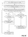
- FIG. 9C-9Dillustrate flowchart diagrams of operations a thermostat communication server and thermostat use to communicate over a plurality of communication channels accordance with embodiments of the present invention
- FIG. 9Eprovides an example data flow chart illustrating the flow of data and events using a plurality of communication channels transmitting different data priority types in accordance with embodiments of the present invention.
- FIGS. 10A-10Bprovide a schematic block diagram and flowchart for a thermostat reporting group with multiple thermostats that gathers events in a common event log in accordance with embodiments of the present invention.
- thermostatsaccording to one or more of the preferred embodiments are applicable for a wide variety of enclosures having one or more HVAC systems including, without limitation, duplexes, townhomes, multi-unit apartment buildings, hotels, retail stores, office buildings and industrial buildings.
- FIG. 1is a diagram illustrating an exemplary enclosure using a thermostat 110 implemented in accordance with the present invention for controlling one or more environmental conditions.
- enclosure 100illustrates a single-family dwelling type of enclosure using a learning thermostat 110 (also referred to for convenience as “thermostat 110 ”) for the control of heating and cooling provided by an HVAC system 120 .
- learning thermostat 110also referred to for convenience as “thermostat 110 ”
- HVAC system 120HVAC system 120
- Alternate embodiments of the present inventionmay be used with other types of enclosures including a duplex, an apartment within an apartment building, a light commercial structure such as an office or retail store, or a structure or enclosure that is a combination of these and other types of enclosures.
- thermostat 110 in FIG. 1incorporate one or more sensors to gather data from the environment associated with enclosure 100 .
- Sensors incorporated in thermostat 110may detect occupancy, temperature, light and other environmental conditions and influence the control and operation of HVAC system 120 .
- Sensors incorporated within thermostat 110do not protrude from the surface of the thermostat 110 thereby providing a sleek and elegant design that does not draw attention from the occupants in a house or other enclosure. As a result, thermostat 110 and readily fits with almost any décor while adding to the overall appeal of the interior design.
- a “learning” thermostatrefers to a thermostat, or one of plural communicating thermostats in a multi-thermostat network, having an ability to automatically establish and/or modify at least one future setpoint in a heating and/or cooling schedule based on at least one automatically sensed event and/or at least one past or current user input.
- a “primary” thermostatrefers to a thermostat that is electrically connected to actuate all or part of an HVAC system, such as by virtue of electrical connection to HVAC control wires (e.g. W, G, Y, etc.) leading to the HVAC system.
- an “auxiliary” thermostatrefers to a thermostat that is not electrically connected to actuate an HVAC system, but that otherwise contains at least one sensor and influences or facilitates primary thermostat control of an HVAC system by virtue of data communications with the primary thermostat.
- the thermostat 110is a primary learning thermostat and is wall-mounted and connected to all of the HVAC control wires
- the remote thermostat 112is an auxiliary learning thermostat positioned on a nightstand or dresser, the auxiliary learning thermostat being similar in appearance and user-interface features as the primary learning thermostat, the auxiliary learning thermostat further having similar sensing capabilities (e.g., temperature, humidity, motion, ambient light, proximity) as the primary learning thermostat, but the auxiliary learning thermostat not being connected to any of the HVAC wires.
- the auxiliary learning thermostatwirelessly communicates with and cooperates with the primary learning thermostat for improved control of the HVAC system, such as by providing additional temperature data at its respective location in the enclosure, providing additional occupancy information, providing an additional user interface for the user, and so forth.
- thermostat 110is a primary learning thermostat and the remote thermostat 112 is an auxiliary learning thermostat
- the scope of the present teachingsis not so limited.
- certain initial provisioning methods that automatically pair associate a network-connected thermostat with an online user accountare particularly advantageous where the thermostat is a primary learning thermostat
- the methodsare more generally applicable to scenarios involving primary non-learning thermostats, auxiliary learning thermostats, auxiliary non-learning thermostats, or other types of network-connected thermostats and/or network-connected sensors.
- thermostatis a primary learning thermostat
- methodsare more generally applicable to scenarios involving primary non-learning thermostats, auxiliary learning thermostats, auxiliary non-learning thermostats, or other types of network-connected thermostats and/or network-connected sensors.
- methods for cooperative, battery-conserving information polling of a thermostat by a remote cloud-based management servermay be particularly advantageous where the thermostat is a primary learning thermostat
- the methodsare more generally applicable to scenarios involving primary non-learning thermostats, auxiliary learning thermostats, auxiliary non-learning thermostats, or other types of network-connected thermostats and/or network-connected sensors.
- Enclosure 100further includes a private network accessible both wirelessly and through wired connections and may also be referred to as a Local Area Network or LAN.
- Network devices on the private networkinclude a computer 124 , thermostat 110 and remote thermostat 112 in accordance with some embodiments of the present invention.
- the private networkis implemented using an integrated router 122 that provides routing, wireless access point functionality, firewall and multiple wired connection ports for connecting to various wired network devices, such as computer 124 .
- Each deviceis assigned a private network address from the integrated router 122 either dynamically through a service like Dynamic Host Configuration Protocol (DHCP) or statically through actions of a network administrator.
- DHCPDynamic Host Configuration Protocol
- These private network addressesmay be used to allow the devices to communicate with each directly over the LAN.
- Other embodimentsmay instead use multiple discrete switches, routers and other devices (not shown) to perform more other networking functions in addition to functions as provided by integrated router 122 .
- Integrated router 122further provides network devices access to a public network, such as the Internet, provided enclosure 100 has a connection to the public network generally through a cable-modem, DSL modem and an Internet service provider or provider of other public network service.
- Public networks like the Internetare sometimes referred to as a Wide-Area Network or WAN.
- WANWide-Area Network
- a public addressis assigned to a specific device allowing the device to be addressed directly by other devices on the Internet. Because these public addresses on the Internet are in limited supply, devices and computers on the private network often use a router device, like integrated router 122 , to share a single public address through entries in Network Address Translation (NAT) table.
- NATNetwork Address Translation
- the routermakes an entry in the NAT table for each communication channel opened between a device on the private network and a device, server, or service on the Internet.
- a packet sent from a device on the private networkinitially has a “source” address containing the private network address of the sending device and a “destination” address corresponding to the public network address of the server or service on the Internet.
- the routerreplaces the “source” address with the public network address of the router and a “source port” that references the entry in the NAT table.
- the server on the Internet receiving the packetuses the “source” address and “source port” to send packets back to the router on the private network which in turn forwards the packets to the proper device on the private network doing a corresponding lookup on an entry in the NAT table.
- Entries in the NAT tableallow both the computer device 124 and the thermostat 110 to establish individual communication channels with a thermostat management system (not shown) located on a public network such as the Internet.
- a thermostat management account on the thermostat management systemenables a computer device 124 in enclosure 100 to remotely access thermostat 110 .
- the thermostat management systempasses information from the computer device 124 over the Internet and back to thermostat 110 provided the thermostat management account is associated with or paired with thermostat 110 . Accordingly, data collected by thermostat 110 also passes from the private network associated with enclosure 100 through integrated router 122 and to the thermostat management system over the public network.
- Other computer devices not in enclosure 100such as Smartphones, laptops and tablet computers (not shown in FIG.
- thermostat management system 1may also control thermostat 110 provided they have access to the public network where the thermostat management system and thermostat management account may be accessed. Further details on accessing the public network, such as the Internet, and remotely accessing a thermostat like thermostat 110 in accordance with embodiments of the present invention is described in further detail later herein.
- thermostat 110may wirelessly communicate with remote thermostat 112 over the private network or through an adhoc network formed directly with remote thermostat 112 .
- thermostat 110may gather information remotely from the user and from the environment detectable by the remote thermostat 112 .
- remote thermostat 112may wirelessly communicate with the thermostat 110 providing user input from the remote location of remote thermostat 112 or may be used to display information to a user, or both.
- embodiments of remote thermostat 112may also include sensors to gather data related to occupancy, temperature, light and other environmental conditions.
- remote thermostat 112may also be located outside of the enclosure 100 .
- FIG. 2is a schematic diagram of an HVAC system controlled using a thermostat designed in accordance with embodiments of the present invention.
- HVAC system 120provides heating, cooling, ventilation, and/or air handling for an enclosure 100 , such as a single-family home depicted in FIG. 1 .
- System 120depicts a forced air type heating and cooling system, although according to other embodiments, other types of HVAC systems could be used such as radiant heat based systems, heat-pump based systems, and others.
- heating coils or elements 242 within air handler 240provide a source of heat using electricity or gas via line 236 .
- Cool airis drawn from the enclosure via return air duct 246 through filter 270 , using fan 238 and is heated through heating coils or elements 242 .
- the heated airflows back into the enclosure at one or more locations via supply air duct system 252 and supply air registers such as register 250 .
- an outside compressor 230passes a gas such as Freon through a set of heat exchanger coils 244 to cool the gas.
- the gasthen goes through line 232 to the cooling coils 234 in the air handler 240 where it expands, cools and cools the air being circulated via fan 238 .
- HVAC system 120may have other functionality such as venting air to and from the outside, one or more dampers to control airflow within the duct system 252 and an emergency heating unit. Overall operation of HVAC system 120 is selectively actuated by control electronics 212 communicating with thermostat 110 over control wires 248 .
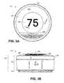
- FIGS. 3A-3Billustrate a thermostat designed in accordance with embodiments of the present invention.
- thermostat 110Inside of thermostat 110 is control circuitry that electrically connects thermostat 110 to an HVAC system, such as HVAC system 120 shown in FIG. 1 and FIG. 2 .
- One or more microprocessors (not shown) inside thermostat 110are available to perform various computations including a backplate processor in backplate 314 for processing information related to the operation and control of HVAC system 120 .
- Another head unit processor(not shown) may be used to control the display and user interface portion in the head unit 312 portion of thermostat 110 and the network protocol.
- a network interface controller or NIC(not shown) is also provided within thermostat 110 enabling wireless communication over a private network such as a LAN and public networks or wide area networks (WANs) such as the Internet.
- WANswide area networks
- thermostat 110is enclosed by housing 316 with a forward-facing surface including a cover 304 and a grille member 308 .
- the grille member 308is designed to compliment the sleek, simple, uncluttered and elegant design of thermostat 110 to while facilitating the integration and operation of sensors located within housing 316 of the thermostat.
- included in the thermostatis passive infrared (PIR) occupancy sensors and temperature sensors behind grille member 308 .
- Additional sensorsmay also include an ambient light sensor (not shown) and an active proximity sensor (not shown) positioned near the top of the thermostat just behind the cover 304 .
- Some embodiments of housing 316include a backplate 314 and a head unit 312 . Housing 316 provides an attractive and durable configuration for one or more integrated sensors used by thermostat 110 and contained therein.
- a central display area 306 of cover 304allows information related to the operation of the thermostat to be displayed while an outer area 310 of cover 304 may be made opaque using a paint or smoke finish.
- central display area 306may be used to display a current temperature as illustrated in FIG. 3A with the numerals, “75” indicating 75 degrees.
- Central display area 316may also be used to display wireless networks available within enclosure 100 and present a user-interface for configuring thermostat 110 to select, access and use one of the wireless networks.
- Embodiments of thermostat 110are circular in shape and have an outer ring 312 for receiving user input.
- Side view of thermostat 110 in FIG. 3Bfurther highlights this curved spherical shape of cover 304 and grille member 308 gently arcing outward matching the corresponding surface portion of outer ring 302 .
- the curvature of cover 304may tend to magnify information displayed in central display area 306 thus making information easier to read by users.
- the shape of thermostat 110not only provides a visually appealing accent when it is mounted on the wall but a natural shape for users to touch and adjust with their hands. Accordingly, the diameter of thermostat 110 may be approximately 80 mm or another diameter that readily fits the hand.
- rotating outer ring 302allows the user to make adjustments, such as selecting a new target temperature. For example, the target temperature may be increased by rotating the outer ring 302 clockwise and decreased by rotating the outer ring 302 counter-clockwise.
- a rechargeable batterylocated within the thermostat 110 .
- the batteryis recharged directly using 24 VAC power off a “C” wire drawn from the HVAC system or a AC-DC transformer coupled directly into the thermostat 110 .
- one or more different types of energy harvestingmay also be used to recharge the internal battery if these direct methods are not available as described, for example, in U.S. Ser. No. 13/034,678, supra, and U.S. Ser. No. 13/267,871, supra.
- Embodiments of the present inventioncommunicate and operate the thermostat 110 in a manner that promotes efficient use of the battery while also keeping the thermostat operating at a high level of performance and responsiveness controlling the HVAC system. Some embodiments may use the battery-level charge and the priority or relative importance of a communication to determine when a thermostat management system located on a public network such as the Internet may communicate with the thermostat 110 . Further details on the communication methods and system used in accordance with these embodiments are described in detail later herein.
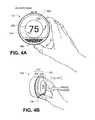
- FIGS. 4A-Billustrate a user's hand controlling a thermostat designed in accordance with embodiments of the present invention.
- thermostat 110is wall-mounted, circular in shape and has a rotatable outer ring 302 for receiving user input.
- Cover 304 on thermostat 110includes central display area 306 for providing information and feedback to the user before, during and after operating thermostat 110 .
- outer area 310 of cover 304delineates an area for the user to push or otherwise manipulate thermostat 110 and thus is made opaque with paint or smoke finish.
- Head unit 312 of thermostat 110slides on to backplate (not shown) and further includes head unit front 402 and head unit frame 404 .
- the head unit front 402includes outer ring 302 , central display area 306 and outer area 310 of cover 304 and grille member 308 designed in accordance with embodiments of the present invention.
- the thermostat 110is controlled by only two types of user input, the first being a rotation of the outer ring 302 as illustrated in FIG. 4A (also referred to as a “rotate ring”), and the second being an inward push on the head unit front 402 until an audible and/or tactile “click” occurs as illustrated in FIG. 4B .
- the inward push illustrated in FIG. 4Bonly causes the outer ring 302 to move forward, while in other embodiments the entire head unit front 402 moves inwardly together when pushed.
- cover 304 and grille member 308do not rotate with outer ring 302 .
- multiple types of user inputmay be generated depending on the way a pushing inward of head unit front 402 is effectuated.
- a single brief push inward of head unit front 402 until the audible and/or tactile click occurs followed by a releasecan be interpreted as one type of user input (also referred to as an “inward click”).
- pushing the head unit front 402 in and holding with an the inward pressure for an amount of time such as 1-3 secondscan be interpreted as another type of user input (also referred to as a “press and hold”).
- other types of user inputcan be effectuated by a user such as double and/or multiple clicks, and pressing and holding for longer and/or shorter periods of time.
- speed-sensitive or acceleration-sensitive rotational inputsmay also be implemented to create further types of user inputs (e.g., a very large and fast leftward rotation specifies an “Away” occupancy state, while a very large and fast rightward rotation specifies an “Occupied” occupancy state).
- FIG. 5illustrates thermostats and computers on a private network 502 connected to a cloud-based management server 516 designed in accordance with aspects of the present invention.
- private network 502is designed to provide network connectivity primarily within and near an enclosure, such as enclosure 100 in FIG. 1 , connecting various devices together such a Smartphone 508 , tablet 510 , computer 512 , thermostat 110 and remote thermostat 112 .
- a router (not shown) in private network 502such as integrated router 122 in FIG. 1 , provides wired and wireless connectivity between these devices using a network protocol such as TCP/IP.
- thermostat 110 and remote thermostat 112are connected wirelessly to private network 502 as a wired connection in the vicinity of the thermostats may not available and/or it is undesirable to include a wired connection socket on thermostat 110 or remote thermostat 112 .
- Thermostat access client 514is a client application designed in accordance with aspects of the present invention to access a cloud-based management server 516 over public network 504 .
- the term “thermostat management system”can be interchangeably referenced as a “cloud-based management server” for the thermostats, or more simply “cloud server”, in various descriptions hereinabove and hereinbelow. Because thermostat access client 514 is designed to execute on different devices, multiple client applications may be developed using different technologies based on the requirements of the underlying device platform or operating system.
- thermostat access client 514is implemented such that end users operate their Internet-accessible devices (e.g., desktop computers, notebook computers, Internet-enabled mobile devices, cellphones having rendering engines, or the like) that are capable of accessing and interacting with the cloud-based management server 516 .
- the end user machine or devicehas a web browser (e.g., Internet Explorer, Firefox, Chrome, Safari) or other rendering engine that, typically, is compatible with AJAX technologies (e.g., XHTML, XML, CSS, DOM, JSON, and the like).
- AJAX technologiesinclude XHTML (Extensible HTML) and CSS (Cascading Style Sheets) for marking up and styling information, the use of DOM (Document Object Model) accessed with client-side scripting languages, the use of an XMLHttpRequest object (an API used by a scripting language) to transfer XML and other text data asynchronously to and from a server using HTTP), and use of XML or JSON (Javascript Object Notation, a lightweight data interchange format) as a format to transfer data between the server and the client.
- XML or JSONJavascript Object Notation, a lightweight data interchange format
- the usermay authenticate to the site (or some portion thereof) by entry of a username and password.
- the connection between the end user entity machine and the systemmay be private (e.g., via SSL).
- the server side of the systemmay comprise conventional hosting components, such as IP switches, web servers, application servers, administration servers, databases, and the like.
- client side codean AJAX shim
- this codeis served to the client machine when the end user accesses the site, although in the alternative it may be resident on the client machine persistently.
- thermostat access client 514may be a stand-alone application or “app” designed to be downloaded and run on a specific device such Smartphone 508 or table 510 device running the Apple iOS operating system, Google Android operating system or others.
- the router (not shown) that services the private network 502can be, for example, a D-Link DIR-655 Extreme N Wireless Router, a Netgear WNDR3700 RangeMax Dual Band Wireless USB Gigabit Router, a Buffalo Technology Nfiniti WZR-HP-G300NH Wireless-N Router, an Asus RT-N16 Wireless Router, Cisco Linksys E4200 Dual Band Wireless Router, or a Cisco Linksys E4200 Dual Band Wireless Router.
- cloud-based management server 516 illustrated in FIG. 5may be accessed over public network 504 by computer devices on private network 502 running thermostat access client 514 .
- Thermostat access client 514may also execute or run on a computer device such as tablet 506 directly connected to the public network 504 .
- each thermostat access client 514has access to a thermostat management account (not illustrated) on cloud-based management server 516 which allows thermostat access client 514 to interact with thermostat 110 or remote thermostat 112 in a variety of different ways.
- thermostat access client 514may be used to access sensor data previously collected from thermostat 110 and remote thermostat 112 then stored on cloud-based management server 516 .
- thermostat access client 514may be used to either remotely control or remotely configure thermostat 110 .
- Thermostat access client 514may also gather other information on thermostat 110 or remote thermostat 112 including a battery-level readings, firmware update levels, diagnostic data, or any other data exposed by the thermostats to thermostat access client 514 .
- thermostat 110 and remote thermostat 112also communicate with cloud-based management server 516 through one or several communication channels established through public network 504 .
- thermostat 110 and remote thermostat 112do not have a public network address and therefore cannot communicate directly on the Internet or other public network without the assistance of the router and corresponding entries in NAT table 518 .
- thermostat 110has a private network address of 192.168.1.108 and a private port number of 60720 while remote thermostat 112 has been configured with a private network address of 192.168.1.110 and three different port numbers 60744, 60743, and 60722.
- thermostat 110initiates the establishment of a communication channel with cloud-based management server 516 having a public network address 107.20.224.12 and public port number 443. Accordingly, the router (not shown) on private network 502 creates an entry in a NAT table 518 identified by NAT PORT 1022 for communications between SOURCE ADDRESS 192.168.1.108 and SOURCE PORT 60720 of thermostat 110 and DESTINATION ADDRESS 107.20.224.12 and DESTINATION PORT 443 of cloud-based management server 516 .
- thermostats 110 and 112may be configured with multiple communication channels to cloud-based management server 516 rather than a single connection as depicted with thermostat 110 .
- thermostat 112initiates the establishment of communication channels over three ports 60744, 60743, and 60722, causing the router to make three more entries in the NAT table 518 identified by NAT PORTs 1044, 1921 and 1758.
- the additional corresponding entries in NAT table 518 identified as NAT PORT 1044, 1921, and 1758include SOURCE ADDRESS 192.168.1.110 and SOURCE PORTS 60744, 60744, 60722 each associated with DESTINATION ADDRESS 107.20.224.12 and DESTINATION PORT 443 of cloud-based management server 516 .
- communications between cloud-based management server 516 and other thermostatsmay take place over a single communication channel as configured on remote thermostat 110 while other embodiments may use multiple communications channels as provided with thermostat 112 .
- the router in private network 502modifies the addresses in packets of data passing over the communication channels between the private network and a server or device on the public network such as cloud-based management server 516 .
- the routermay receive a packet from remote thermostat 110 having a SOURCE ADDRESS field of 192.168.1.108 and a SOURCE PORT of 60720 combined with a DEST ADDRESS of 107.20.224.12 and DEST PORT 443 of cloud-based management server 516 .
- the routerBefore placing this packet on the Internet, the router references NAT table 518 and replaces the SOURCE ADDRESS field and SOURCE PORT field values with the public address 76.21.3.203 assigned to the router and the corresponding NAT port 1022 respectively.
- a resulting modified packet header 520 in FIG. 5 sent over the public networkhas the original destination address and destination port but the source address and port are changed to the public address of the router and port number from NAT table 518 .
- thermostats 110 and 112may communicate over their respective communication channels on the public network 504 to cloud-based management server 516 .
- an enlarged battery image 110 A next to thermostat 110shows schematically a battery-level of the battery inside of thermostat 110 .
- the battery image 110 Ain this example, appears about 80% charged thus representing the battery-level inside thermostat 110 to be almost fully charged.
- an enlarged battery image 112 A adjacent to remote thermostat 112appears about 20% charged thus indicating that the battery inside of thermostat 112 has a low battery-level.
- embodiments of the present inventionmay incorporate one or multiple different strategies in communicating and operating a thermostat.
- cloud-based management server 516monitors battery-levels on the thermostats and judiciously control the communications according to a priority assigned to the data.
- cloud-based management server 516implements aspects of the present invention however alternate embodiments may distribute functionality from cloud-based management server 516 to one or several servers within the system.
- thermostat 110 and thermostat 112have initiated and established their respective communication channels with cloud-based management server 516 and the router on private network 502 has created NAT table 518 as previously illustrated in FIG. 5 .
- the thermostats 110 / 112may enter into a low power state while waiting for either (i) a local event that merits wake-up, such as a particular temperature threshold being detected by the temperature sensors, or a detected proximity of a user detected by the proximity sensors, or (ii) a next event or request from cloud-based management server 516 that merits wake-up.
- a local event that merits wake-upsuch as a particular temperature threshold being detected by the temperature sensors, or a detected proximity of a user detected by the proximity sensors, or (ii) a next event or request from cloud-based management server 516 that merits wake-up.
- each thermostat 110 / 112Prior to entering into a low power state, each thermostat 110 / 112 sends a connection-opening long-polling packet to the thermostat communication server 620 .
- cloud-based management server 516maintains a long-polling communication with thermostats 110 / 112 allowing the communication channels to remain open even though the actual data exchanged may be infrequent or subject to long delays. This not only uses the battery-charge of the thermostats more efficiently but reduces the overhead and delay associated with reestablishing a communication channel for each data transmission.
- cloud-based management server 516maintains the long-polling communication in a manner that preserves the entry in NAT table 518 by sending a keep-alive priority packet at regular keep-alive intervals.
- the keep-alive priority packetis consistent with a keep-alive facility built into a TCP/IP protocol stack. If no messages need to otherwise be sent to the thermostats 110 / 112 within the long-polling time interval, the protocol stack sends one or more “keep-alive” packets to the router on private network 502 at respective keep-alive intervals that are less than the long-polling time interval, thereby preserving the entry in NAT table 518 .
- the keep-alive intervalsare substantially less than the interval over which many common routers might otherwise flush their NAT table with respect to that particular connection.
- thermostats 110 and 112may wake from a low power state to check on their respective battery-levels and perform other administrative functions.
- the battery-levelis transmitted over a wireless connection from each thermostat 110 and 112 through an access point 606 on the private network and then stored for future reference by thermostat communication server 620 .
- battery image 110 Aappears about 80% charged representing the battery-level inside thermostat 110 to be almost fully charged while battery image 112 A appears about 20% charged thus indicating that the battery inside of thermostat 112 is at a low level.
- cloud-based management server 516updates this data in a device-battery-charge table 616 that includes a device address, a battery-level, and a keep-alive interval used for the corresponding communication channel.
- device-battery-charge table 616provides that device address 76.21.3.203:1022 (corresponding to thermostat 110 by way of NAT table 518 ) has a “high” battery-level and a keep-alive interval set to 5000 time units.
- device addresses 76.21.3.203:1044, 76.21.3.203:1921, and 76.21.3.203:1758(corresponding to thermostat 112 by way of NAT table 518 ) in device-battery-charge table 616 all have a “low” battery-level and a longer keep-alive interval set to 10000.
- Some embodiments of cloud-based management server 516may set the keep-alive interval shorter if the battery-level is high to reduce the chance that an entry in the NAT table 518 will be flushed by the router. If the battery-level is “low”, the keep-alive interval may be set to a maximum long-poll interval that represents a maximum time interval not likely to exceed a NAT time-out period of most router devices.
- cloud-based management server 516may further use device-battery-charge table 616 to help determine when data should be communicated from cloud-based management server 516 to one or more thermostats.
- one embodimentfurther creates a power-priority table 618 that associates low and high battery-levels reported from each thermostat with high thermostatic importance data or low thermostatic importance data.
- power-priority table 618establishes a trade-off between the importance assigned to data being communicated compared with the drain on the current battery charge associated with the thermostat. For example, data communications with data classified as high thermostatic importance data may be filtered and transmitted even when the battery is low since the data is considered of higher importance to the overall operation of cloud-based management server 516 and the thermostat.
- a low battery-levelmay be between 0 and 39% of charge capacity.
- thermostatic importance data communications classified under a low thermostatic importancemay note be transmitted when the battery level is low as indicated in power-priority table 618 . Since the battery is not fully charged, low thermostatic importance data may not be transmitted in accordance with power-priority table 618 to preserve energy on the battery of the thermostat. Accordingly, low and high thermostatic importance data types are transmitted in accordance with some embodiments when the battery-level is detected as high or in a range from 80% to 100% charged.
- power-priority table 618three battery levels and three levels of thermostatic importance.
- data consider to be high thermostatic importanceis transmitted while medium and low thermostatic importance data is not sent.
- the battery levelis at a medium level, data considered of both high and medium thermostatic importance is transmitted. If the battery level is at least at a high level then data considered to be of low, medium and high thermostatic importance is transmitted.
- Further additional embodimentsmay also use more than three battery-levels and three data priority level types for the data as well depending on the particular design and implementation requirements.
- the percentage charge for low, medium and high battery-levelsmay include different ranges of charge that do not necessarily include the aforementioned 0-39% charge for a low battery-level, 40% to 79% for a medium battery-level, and 80% to 100% for a high battery-level.
- the data communicationsmay be classified in a number of different ways and often will be determined based on the particular implementation requirements of the cloud-based management server 516 and performance requirements for the thermostats.
- a high-priority data typemay include data communications actively requesting a thermostat perform some function. This may include a data communication from cloud-based management server 516 requesting thermostat 110 or 112 to change a temperature setpoint.
- Another high-priority data typemay include a data communication requesting thermostat 110 or 112 to turn on or turn off a cooling function.
- low-priority data typesmay include certain operations or functions deemed less critical for a thermostat to perform immediately.
- Downloading a software update from cloud-based management server 516 to a thermostatis one example of a low-priority communication as the software update is not required and likely does not affect the immediate operation of the thermostat.
- FIG. 7illustrates a cloud-based management server 516 that both conserves energy and promotes high-performance operation of thermostats designed in accordance with embodiments of the present invention.
- cloud-based management server 516includes a processor 704 configured to execute one or more instructions, a memory 702 holding instructions executable on the processor, a network interface controller 706 capable of communication over a network such as the Internet, a storage device 710 , a display adapter and monitor 712 to display information from the server on the monitor, and peripheral drivers & devices 714 that includes keyboards, mice and other interfaces for controlling the server.
- a CD-ROM/DVD device 716 with mediamay be attached to peripheral drivers & devices 714 holding various embodiments of the present invention tangibly embodied in a computer program product.
- processes in memory 702may include a battery-level collection process 718 that stores a battery-level associated with the battery used to power a thermostat.
- the battery-levelin some embodiments is provided by the thermostat over a communication channel established over a network between the thermostat management system and the thermostat and provides an indication of remaining energy in the battery associated with the thermostat.
- the battery-level collection processis able to collect these battery-levels over a long period of time as a result of ongoing communications between the thermostat and the cloud-based management server 516 , which includes the long-polling process that keeps the communication channels open between the cloud-based management server 516 and thermostats.
- the battery-level datais stored in a device-battery-charge table 616 as illustrated in FIG. 6 and may be in a local storage area on cloud-based management server 516 or remotely accessed in a database or other remote storage area.
- Some embodimentsmay further include a data priority process 720 in memory 702 that classifies and prioritizes one or more types of data to be transmitted to the thermostat over a communication channel.
- data priority process 720classifies the data transmission according to a data priority ranging from a low thermostatic importance data type to a high thermostatic importance data type.
- the low thermostatic importance datais of lesser importance to the operation of the thermostat management system and the thermostat.
- a low thermostatic importance data typemay include a software update as the software update may not be required for the thermostat to operate.
- high thermostatic importance data typesmay include data of higher importance to the operation of the thermostat management system such as a request to change a setpoint in a thermostat or turn-on heating or cooling in the HVAC system.
- Further embodimentsmay also include a power-classification transmission process 722 that transmits data to a thermostat depending on a classification of the data and the battery-level associated with the thermostat.
- the data priority classificationranges from a low thermostatic importance data type to a high thermostatic importance data type depending on the importance of the data to the overall operation of cloud-based management server 516 and the thermostat. Consequently, low thermostatic importance data may not be transmitted when a battery-level is low in order to conserve the battery power remaining on the thermostat.
- the power-classification transmission process 722may transmit all data classifications when the battery-level associated with a thermostat is fully-charged or “high”.
- Embodiments of the present inventionmay also include a long-polling process 724 in memory 702 to facilitate keeping the communication channel open with a thermostat.
- This long-polling process 724initially receive receives a request over the network from a thermostat to establish the communication channel between the cloud-based management server 516 located on a public network and the thermostat located on a private network.
- cloud-based management server 516has a public network address registered on the Internet while the thermostat has a shared public network address provided through an entry in a NAT table from a router on a private network, such as NAT table 518 in FIG. 5 .
- the long-polling process 724further configures a network communication protocol, such as TCP/IP, to occasionally transmit a keep-alive packet from the thermostat management system back to the network-attached thermostat over the communication channel.
- a network communication protocolsuch as TCP/IP
- the keep-alive packet sent to the thermostatacknowledges establishment of the communication channel but may not include a payload or data that needs processing.
- Long-polling process 724may set the time interval for sending these keep-alive packets at maximum time interval not to exceed a NAT time-out period of a router device. The receipt of the keep-alive packet before the NAT time-out period keeps the entry in the NAT table current and the communication channel from being disconnected.
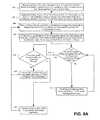
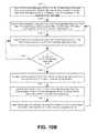
- FIG. 8Aillustrates a flowchart diagram of the operations that a thermostat communication server uses to coordinate communications with a battery powered thermostat that both conserves the energy of the battery and promotes performance of the thermostat.
- the thermostat communication serversuch as cloud-based management server 516 in FIG. 6 , receives a request from a thermostat powered by a battery to establish a communication channel between the thermostat and the thermostat communication server over a network.
- a routerplaces an entry in a NAT table, such as NAT table 518 in FIG. 5 , allowing the thermostat on a private network behind a router to then communicate with thermostat communication server on the Internet, a public network.
- the entry in the NAT tablewill not be removed and the communication channel will remain open as long as any gap in communication from the thermostat communication server and the thermostat does not exceed a NAT time-out value associated with router.
- thermostat communication serverclassifies one or more types of data to be transmitted to the thermostat over the communication channel according to a thermostatic importance ranging from a low thermostatic importance to a high thermostatic importance classification.
- the low thermostatic importance data typeincludes data of lesser importance to the operation of the overall thermostat management system and thermostat. These may include optional functions to be performed on the thermostat such as software update or other maintenance.
- the high thermostatic importance data typeincludes data of higher importance to the operation of the thermostat management system and the thermostat and generally includes requests to actively perform an action on the thermostat such as changing a setpoint, turning-on/off heating or cooling or checking ambient temperature in a residence or commercial location where the thermostat is located.
- thermostat communication serverstores a battery-level associated with a thermostat in a storage area accessible by the thermostat communication server.
- each thermostatperiodically checks its own battery and provides the battery-level to the thermostat communication server over a communication channel established over the network.
- Battery-level information for each thermostatmay be stored in a device-battery-charge table, such as device-battery-charge table 616 as illustrated in FIG. 6 .
- thermostat communication servermay configure a long-poll interval for transmitting a keep-alive packet over the communication channel to the thermostat.
- the thermostat communication serversets the long-poll interval to a maximum value not to exceed a NAT timeout period used by most routers, which is often approximately 100 minutes.
- thermostat communication servermay request to terminate the communication channel when the long-poll interval has elapsed and wait for new communication channel to be established by the thermostat.
- thermostat communication serverchecks the most recent battery-level of the thermostat before sending. ( 810 -Yes) One embodiment determines if there is a low battery-level associated with the thermostat ( 814 -Yes) that only data classified as high thermostatic importance data should be transmitted. ( 816 ) This preserves some of the battery charge in the thermostat by not sending low thermostatic importance data.
- thermostat communication serverhave predetermined classifications setup in advance according to a particular configuration requirement. If the data is of higher importance to the operation of the thermostat management system then the data is classified as a high thermostatic importance data type and should be sent even when there is a low battery-level.
- high thermostatic importance datamay include instructions sent to a thermostat actively requesting the thermostat change a temperature setpoint or other setting.
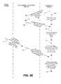
- FIG. 8BAn example data flow chart in FIG. 8B illustrates the flow of data and events when thermostat communication server transmits data based on a battery-level of a thermostat and priority associated with the data.
- the thermostatinitiates establishment of a communication channel with thermostat communication server causing a router to creates entry in the NAT table. ( 826 ) To save energy, the thermostat enters a low power mode and waits for the next event. ( 828 ). After a period of time, the management server sends a keep-alive packet before the NAT table entry is removed.
- the thermostatwakes from the low power mode and sends a low battery-level to the thermostat communication server indicating the battery-level on the thermostat is nearly discharged ( 832 )—the thermostat then returns to a low power mode to conserve the battery use.
- Thermostat communication serverassociates the low battery-level with the thermostat and stores the results in a storage area.
- a client devicesuch as tablet 506 running thermostat access client 514 in FIG. 5 , requests thermostat communication server to change a thermostat setting.
- Thermostat communication serverclassifies request as a high thermostatic importance data type to be transmitted even though the battery on the thermostat is at a low level.
- thermostatreceives the data transmission and fulfills the request to change the thermostat setting.
- thermostatic importance classificationsmay use more than two battery levels and more than two corresponding thermostatic importance classifications for data such as a three classification system with low, medium, and high thermostatic importance classification data types.
- a battery powered thermostat and system illustrated in FIG. 9A-9Buses a plurality of communication channels to exchange data classified with different priority in accordance with embodiments of the present invention.
- the thermostat 112receives data of different priority from cloud-based management server 516 over corresponding different communication channels and, depending on the battery-level, may either process or discard the data received.
- the processing associated with this embodimentis distributed partly on cloud-based management server 516 and partly on thermostat 112 .
- thermostat 112can determine the battery-level without polling or indirectly gathering data thus resulting in a more accurate processing of data packets received from thermostat communication server 620 .
- thermostat 112 in FIG. 9Ahas established two wireless communication channels using private network address and port combinations 192.168.1.110:60744 and 192.168.1.110:60743. These private network addresses on thermostat 112 have corresponding entries in NAT table 518 in FIG. 5 identified with NAT port entries 1044 and 1921.
- Cloud-based management server 516 in FIG. 9Astores corresponding public addresses and port numbers 76.21.3.203:1044 and 76.21.3.203:1921 for thermostat 112 in a priority transmission table 902 and also associates a high and low-priority data type to each address as illustrated.
- cloud-based management server 516classifies data to be sent to the thermostat as being a low or high-priority data type and then sends over the appropriate communication channel or public address as indicated in priority transmission table 902 .
- Datapasses over public network 504 , private network 502 , and wirelessly from access point 606 illustrated in FIG. 9A onto thermostat 112 .
- a power-priority table 904identifies that the recent battery-level of thermostat 112 is at a low level, as illustrated by battery image 112 A, and that ports 60744 and 60743 are used to process high and low data types respectively. Because the most recent battery-level was low, power-priority table 904 also indicates in this example that the Wifi module has been configured to ignore or discard low-priority data arriving on ports 60743 and process only high-priority data received over port 60744.
- thermostat 112may update the configuration of the Wifi module to accept or discard packets depending on the battery-level the thermostat 112 detects. If thermostat 112 later determines the battery-level is high, thermostat 112 reconfigures WiFi module to subsequently process both low and high-priority data packets arriving over both ports.
- Wifi modulemay also be configured to use greater or fewer ports and process either greater or fewer data priority types. For example, three communication channels may be used to process either high-priority, medium-priority or low-priority data types rather than just either high-priority or low-priority data types.
- thermostat 908is similar to thermostat 112 in FIG. 9A except that thermostat 908 also illustrates and highlights selected internal components including a Wifi module 912 and antenna, a head unit processor 914 with associated memory 915 , a backplate processor 916 with associated memory, and sensors 922 (e.g., temperature, humidity, motion, ambient light, proximity).
- head unit processor 914can be a Texas Instruments AM3703 Sitara ARM microprocessor while backplate processor 916 , which may be more specifically referenced to as a “microcontroller”, can be a Texas Instruments MSP430F microcontroller. Further details regarding the physical placement and configuration of the thermostat head unit, backplate, and other physical elements are described in the commonly assigned U.S. Ser. No. 13/199,108, supra.
- the backplate processor 916is a very low-power device that, while having some computational capabilities, is substantially less powerful than the head unit processor 914 .
- the backplate processor 916is coupled to, and responsible for polling on a regular basis, most or all of the sensors 922 including the temperature and humidity sensors, motion sensors, ambient light sensors, and proximity sensors.
- sensors 922that may not be located on the backplate hardware itself but rather are located in the head unit, ribbon cables or other electrical connections between the head unit and backplate are provided for this purpose.
- there may be other sensors (not shown) for which the head unit processor 914 is responsiblewith one example being a ring rotation sensor that senses the user rotation of the outer ring 302 (see FIGS. 4A-4B , supra).
- Each of the head unit processor 914 and backplate processor 916is capable of entering into a “sleep” state, and then “waking up” to perform various tasks.
- the backplate processor 916which in some embodiments will have a low-power sleep state that corresponds simply to a lower clock speed, generally enters into and out of its sleep mode substantially more often than does the more powerful head unit processor 914 .
- the backplate processor 916is capable of waking up the head unit processor 914 from its sleep state.
- the head unit processor 914is allowed to sleep when its operations are not being called for, while the backplate processor 916 performs polling of the sensors 922 on an ongoing basis, maintaining the sensor results in memory 917 .
- the backplate processor 916will wake up the head unit processor 914 in the event that (i) the sensor data indicates that an HVAC operation may be called for, such as if the current temperature goes below a currently active heating setpoint, or (ii) the memory 917 gets full and the sensor data needs to be transferred up to the head unit processor 914 for storage in the memory 915 .
- the sensor datacan then be pushed up to the cloud server (thermostat management server) during a subsequent active communication session between the cloud server and the head unit processor 914 .
- Wifi module 912In the case of Wifi module 912 , one embodiment may be implemented using Murata Wireless Solutions LBWA19XSLZ module, which is based on the Texas Instruments WL1270 chipset supporting the 802.11b/g/n WLAN standard. Embodiments of the present invention configure and program Wifi module 912 to allow thermostat 908 to enter into a low power or “sleep” mode to conserve energy until one or several events occurs. For example, in some embodiments the Wifi module 912 may leave this low power mode when a user physically operates thermostat 908 , as illustrated in FIGS. 4A and 4B , which in turn may also cause activation of both head-unit processor 914 and backplate processor 916 for controlling functions in head-unit 312 and backplate 314 portions of thermostat 110 depicted in FIG. 3B .
- Wifi module 912may wake from a low power mode at regular intervals in response to a beacon from wireless access point 912 .
- Wifi module 912may briefly leave the low power mode to acknowledge the beacon as dictated by the appropriate wireless standard and then return to a low power mode without activating the processors or other components of thermostat 908 in FIG. 9B .
- Wifi module 912may also respond to the beacon by awaking briefly and then activating backplate processor 916 , head unit processor 914 , or other portions of thermostat 908 to gather data through sensors 922 and store the results in a data log 926 with a time stamp, event type and corresponding data listed for future reference.
- backplate processor 916may collect data in data log 926 and store in memory 920 for a period of time or until the log reaches a maximum predetermined size. At that point, the backplate processor 916 may wake head unit processor 914 to coordinate an upload of the data log 926 stored in memory 920 over a public network, such as the Internet, to cloud-based management server 516 . Uploading data log 926 less frequently saves time and energy associated with more frequent transmission of individual records or log entries.
- WiFi module 912may selectively filter an incoming data packet to determine if the header is merely an acknowledgement packet (i.e., a keep-alive packet) or contains a payload that needs further processing. If the packet contains only a header and no payload, the WiFi module 912 may be configured to either ignore the packet or send a return acknowledgement to the thermostat management system or other source of the packet received.
- an acknowledgement packeti.e., a keep-alive packet
- the WiFi module 912may be configured to either ignore the packet or send a return acknowledgement to the thermostat management system or other source of the packet received.
- WiFi module 912may be used to establish multiple communication channels between thermostat 112 and cloud-based management server 516 as described and illustrated in FIG. 9A .
- thermostat 112uses the multiple communication channels to receive different types of data classified with different levels of priority.
- Wifi module 912may be programmed to use one or more filters and a wake-on-LAN feature to then selectively ignore or discard data arriving over one or more of these communication channels. For example, low-priority data arriving over a port on Wifi module 912 may be discarded by disabling the corresponding wake-on-LAN feature associated with the port. This allows the communication channel to continue to operate yet conserves battery power by discarding or ignoring the low-priority packets.
- FIGS. 9C-9Dconcern the operations on cloud-based management server 516 and thermostat 112 in accordance with embodiments of the present invention as illustrated in FIGS. 9A and 9B .
- flowchart diagram in FIG. 9Cprovides the operations used by a thermostat communication server to communicate over a plurality of communication channels with a battery powered thermostat.
- thermostat communication serversuch as cloud-based management server 516 in FIG. 9A , receives a request from a thermostat powered by a battery to establish a plurality of communication channel between the thermostat and the thermostat communication server over a network.
- a routerplaces a plurality of entries in a NAT table, such as NAT table 518 in FIG.
- thermostat communication serverclassifies one or more types of data to be transmitted to the thermostat over the communication channel according to a data priority ranging from a low-priority data type to a high-priority data type.
- the low-priority data typeincludes data of lesser importance to the operation of the overall thermostat management system and thermostat. These may include optional functions to be performed on the thermostat such as software update or other maintenance.
- the high-priority data typeincludes data of higher importance to the operation of the thermostat management system and the thermostat and generally includes requests to actively perform an action on the thermostat such as changing a setpoint, turning-on/off heating or cooling or checking ambient temperature in a residence or commercial location where the thermostat is located.
- thermostat communication servermay configure a long-poll interval for transmitting keep-alive packets over the plurality of communication channels to the thermostat. ( 932 )
- the thermostat communication serversets the long-poll interval to a maximum value not to exceed a NAT timeout period used by most routers, which is often approximately 100 minutes.
- thermostat communication servermay request the thermostat to terminate and reestablish the communication channel when the timer associated with the long-poll interval expires to help make sure the communication channel is available and operating properly.
- thermostat communication serverchecks the priority of the data and sends over the proper communication channel. Accordingly in one embodiment, if the data is classified as low-priority ( 940 -Yes), thermostat communication server sends the data over a communication channel reserved for low-priority data transmissions. ( 942 ) Alternatively, if the data is classified as high-priority and not low-priority ( 940 -No), thermostat communication server sends the data over a communication channel reserved for high-priority data transmissions. ( 948 ) In this embodiment, thermostat communication server segregates the data on different communication channels but allows the thermostat to determine whether to process or discard the data as it easy easier for the thermostat to obtain battery-level data and make a decisions.
- FIG. 9Dis a flowchart diagram of the complimentary operations performed on a thermostat to conserve battery energy yet process data at a high level of performance.
- a thermostatsuch as thermostat 112 in FIG. 9A
- a thermostatmay wake from a low power state once every 100 ms to respond to a wireless strobe from an access point 924 and may also check on a battery-level. It is also possible that a wake-on-LAN event wakes the thermostat causing it to leave the low power state and process a data packet received over one or several communication channels reserved for different priority levels of data.
- the thermostatmay determine that the communication channels with thermostat communication server, such as with thermostat communication server 620 , have not been established.
- thermostat communication serversuch as with thermostat communication server 620
- one embodiment of the present inventionmay request and establish two communication channels between the thermostat communication server and the thermostat.
- the thermostatreserves the first and second communication channels on the thermostat to receive data classified as low and high-priority data types.
- the thermostatinitially configures its Wifi module, such as Wifi module 912 in FIG. 9B , to receive low and high-priority data packets from each of the several communication channels using a built-in wake-on-LAN feature.
- thermostatmay then return to a low power state waiting for the next event or receipt of data.
- the thermostatdetermines if a data packet has been received and requires further processing.
- the Wifi module on the thermostatmay inspect the data packet header or payload and determine that the data packet needs no further processing and can be discarded.
- the data packetmay be discarded if it is a keep-alive packet meant to preserve the NAT table entries in the router or if the packet otherwise has no payload data associated with it. If the packet is discarded, the thermostat may conserve overall power consumed because other components in the thermostat, such as head unit processor 914 or backplate processor 916 , can remain in a low power state. ( 962 )
- thermostatmay activate or power-up other portions of the thermostat to service the data packet received.
- thermostatmay activate head unit processor 914 to perform a change of a setpoint or other feature on the thermostat or may activate back plate processor 916 to gather sensor information as requested from thermostat communication server 620 .
- embodiments of the present inventioncheck the current battery-level of the thermostat and adjust the communication channels to either accept or discard subsequent data packets. If the thermostat determines the battery charge is at or below a low battery-level, ( 968 -Yes) the Wifi module is configured to discard subsequent data received over a first communication channel reserved to received low priority data. ( 972 ) As previously described, some embodiments discard packets over a communication channel and port of the Wifi module by turning off a wake-on-LAN feature for the channel. This causes subsequent low priority packets received on the channel to be ignored and discarded.
- the Wifi moduleis configured to process packets on the second communication channel using a filter to locate the proper port number and enabling the wake-on-LAN feature for the selected filter.
- the battery chargeis above the low battery-level ( 968 -No) then embodiments of the present invention enable processing of subsequently received packets over the first and second communication channels.
- the thermostatAfter checking the battery-level and adjusting the Wifi module, the thermostat returns to a low power state to conserve energy consumption and await the next event and/or data to be processed. ( 958 )
- An example data flow chart in FIG. 9Eillustrates the flow of data and events using a plurality of communication channels to transmit different priority levels of data.
- the thermostatinitiates establishment of a a plurality of communication channels with thermostat communication server causing a router to creates corresponding entries in a NAT table.
- a first communication channelis reserved for low-priority types of data and a second communication channel is reserved for high-priority types of data.
- the thermostatenters a low power mode and waits for the next event. ( 964 ). After a period of time, a long-poll interval expires causing the thermostat communications server to send a keep-alive packet before the NAT table entry is removed.
- the thermostatwakes from the low power mode and sensing a low battery-level and making note of the local condition. In this embodiment, the thermostat does not forward to the thermostat communication server since it is up to the thermostat to determine whether to process the received data packets. Instead, thermostat turns off a wake-on-LAN (WOL) feature for all ports except the port receiving high-priority types of data.
- WOLwake-on-LAN
- subsequently received packets received on the first communication channelmay be discarded since the low-priority data is reserved for the first communication channel.
- a client devicesuch as tablet 506 running thermostat access client 514 in FIG. 5 , requests that thermostat communication server downloads a software update to the thermostat.
- Thermostat communication serverclassifies request as a low-priority data type and transmits over the first communication channel regardless of the battery-level on the thermostat.
- thermostat communication serversegregates different priority data types on different communication channels and lets the thermostat decide whether to discard or process the packets received. Eventually, the thermostat receives the software update request but discards the packets as the battery-level is low and the first communication channel is configured to ignore the low-priority data packets that it may receive. ( 976 ).
- FIGS. 10A-10Bprovide a schematic block diagram and flowchart for creating a thermostat reporting group with multiple thermostats and gathering reporting events in a common event log.
- a thermostat reporting group 1002is formed from several thermostats in a network including thermostat 1004 , thermostat 1006 , thermostat 1008 and thermostat 1010 whereupon each thermostat has a current battery-level as represented by battery images 1004 A, battery image 1006 A, battery image 1008 A and battery image 1010 A respectively.
- a proxy reporting thermostatis selected from the thermostat reporting group to receive the event log information from other members of the group and then upload over a network to a central server.
- thermostat 1004is selected as the proxy reporting thermostat since the corresponding battery-level indicated by battery image 1004 A is the highest within the thermostat reporting group.
- thermostat 1004gathers log data over the network from other thermostats 1006 , 1008 and 1010 through local transfers 1012 , 1014 , and 1016 respectively. These local transfers include the log data from each thermostat combined into a common log 1016 identifying a time stamp, event type, device ID and data content for each entry. After a period of time or when memory (not shown) in thermostat 1004 fills up, the common log 1016 is uploaded over a communication channel to a central server such as the cloud-based management server 516 .
- This approachallows event log information to be gathered using fewer uploads than would be required if each thermostat was required to upload individually. It also allows thermostats having a low battery-level to preserve their battery charge while still allowing such data to be collected and analyzed on a server such as cloud-based management server 516 in FIG. 5 .
- FIG. 10Bis a flowchart diagram of the operations associated with gathering reporting events on a proxy reporting thermostat and common event log in accordance with embodiments of the present invention.
- a thermostat reporting groupis created from a plurality of battery powered thermostats on a network. ( 1016 ). Each battery powered thermostat individually records events in a respective event log corresponding to the one or more operations and events occurring on a thermostat.
- the eventsmay include sensor information provided from humidity sensors, temperature sensors, passive infra-red sensors, ambient light sensors, active proximity sensors or other sensors incorporated into each thermostat.
- Event logsmay also include information describing current or changed settings on a thermostat and the time stamp associated with when these settings were changed.
- embodiments of the present inventionselect a proxy reporting thermostat to represent the other thermostats. ( 1018 ).
- the proxy reporting thermostatis selected based on having the highest battery-level compared with the other battery powered thermostats in the thermostat reporting group. For example, thermostat 1004 in FIG. 10A has the highest charged battery in the group and is thus selected as the proxy reporting thermostat.
- the proxy reporting thermostatgathers events recorded from each of the thermostats in the thermostat reporting group.
- Proxy reporting thermostatmay collect these events from each thermostat in the thermostat reporting group using a wireless ad-hoc connection or a wireless connection made available through a network access point or router.
- the proxy reporting thermostatgenerally continues to collect the data from the other thermostats until storage on the proxy reporting thermostat is full or has reached a maximum allocation for such logs.
- a thermostatmay have allocated 500 megabytes for storing the log information from multiple thermostats before triggering the upload process.
- one embodiment of the proxy reporting thermostatestablishes a communication channel to a thermostat management system to store the thermostat events.
- a thermostat management systemFor example, this may be connection over the Internet between the thermostat on a private network and the thermostat management system.
- one embodimentuploads events gathered on the proxy reporting thermostat over the communication channel to the thermostat management system on behalf of the thermostats in the thermostat reporting group.
- embodiments of the present inventionclear the storage area on the proxy reporting thermostat of the events gathered from the thermostat reporting group. ( 1028 ). This makes way for storage of more events in the event log on the proxy reporting thermostat.
- thermostatcan include thermostats having direct control wires to an HVAC system, and can further include thermostats that do not connect directly with the HVAC system, but that sense an ambient temperature at one location in an enclosure and cooperatively communicate by wired or wireless data connections with a separate thermostat unit located elsewhere in the enclosure, wherein the separate thermostat unit does have direct control wires to the HVAC system. Accordingly, the invention is not limited to the above-described embodiments, but instead is defined by the appended claims in light of their full scope of equivalents.
Landscapes
- Engineering & Computer Science (AREA)
- Computer Networks & Wireless Communication (AREA)
- Signal Processing (AREA)
- Automation & Control Theory (AREA)
- Physics & Mathematics (AREA)
- General Physics & Mathematics (AREA)
- Theoretical Computer Science (AREA)
- General Engineering & Computer Science (AREA)
- Telephonic Communication Services (AREA)
- Selective Calling Equipment (AREA)
Abstract
Description
Claims (18)
Priority Applications (19)
| Application Number | Priority Date | Filing Date | Title |
|---|---|---|---|
| US13/317,423US9489062B2 (en) | 2010-09-14 | 2011-10-17 | User interfaces for remote management and control of network-connected thermostats |
| US13/275,307US9098279B2 (en) | 2010-09-14 | 2011-10-17 | Methods and systems for data interchange between a network-connected thermostat and cloud-based management server |
| EP11840968.9AEP2641172B1 (en) | 2010-11-19 | 2011-11-18 | Methods and systems for data interchange between a network-connected thermostat and cloud-based management server |
| CN201180055867.1ACN103262041B (en) | 2010-11-19 | 2011-11-18 | Thermostat and method for communicating data between thermostat and thermostat management server |
| PCT/US2011/061503WO2012068526A1 (en) | 2010-11-19 | 2011-11-18 | Methods and systems for data interchange between a network-connected thermostat and cloud-based management server |
| CA2818546ACA2818546C (en) | 2010-11-19 | 2011-11-18 | Methods and systems for data interchange between a network-connected thermostat and a cloud-based management server |
| JP2013540079AJP5925796B2 (en) | 2010-11-19 | 2011-11-18 | Method and system for exchanging data between a networked thermostat and a cloud-based management server |
| EP19190528.0AEP3582446A1 (en) | 2010-11-19 | 2011-11-18 | Methods and systems for data interchange between a network-connected thermostat and cloud-based management server |
| US13/466,815US9046898B2 (en) | 2011-02-24 | 2012-05-08 | Power-preserving communications architecture with long-polling persistent cloud channel for wireless network-connected thermostat |
| US13/530,901US8627127B2 (en) | 2011-02-24 | 2012-06-22 | Power-preserving communications architecture with long-polling persistent cloud channel for wireless network-connected thermostat |
| US14/469,577US9279595B2 (en) | 2010-09-14 | 2014-08-26 | Methods, systems, and related architectures for managing network connected thermostats |
| US14/600,469US9709290B2 (en) | 2010-09-14 | 2015-01-20 | Control unit with automatic setback capability |
| US14/720,578US9851729B2 (en) | 2010-11-19 | 2015-05-22 | Power-preserving communications architecture with long-polling persistent cloud channel for wireless network-connected thermostat |
| US14/738,149US20150354846A1 (en) | 2010-09-14 | 2015-06-12 | Methods and apparatus for control unit with a variable assist rotational interface and display |
| US14/812,804US9846443B2 (en) | 2010-09-14 | 2015-07-29 | Methods and systems for data interchange between a network-connected thermostat and cloud-based management server |
| US14/984,876US10142421B2 (en) | 2010-09-14 | 2015-12-30 | Methods, systems, and related architectures for managing network connected devices |
| JP2016084428AJP6258394B2 (en) | 2010-11-19 | 2016-04-20 | Method and system for exchanging data between a networked thermostat and a cloud-based management server |
| JP2017234255AJP6457620B2 (en) | 2010-11-19 | 2017-12-06 | Method and system for exchanging data between a networked thermostat and a cloud-based management server |
| US15/854,539US10732651B2 (en) | 2010-11-19 | 2017-12-26 | Smart-home proxy devices with long-polling |
Applications Claiming Priority (37)
| Application Number | Priority Date | Filing Date | Title |
|---|---|---|---|
| US12/881,430US8510255B2 (en) | 2010-09-14 | 2010-09-14 | Occupancy pattern detection, estimation and prediction |
| US12/881,463US8606374B2 (en) | 2010-09-14 | 2010-09-14 | Thermodynamic modeling for enclosures |
| US41577110P | 2010-11-19 | 2010-11-19 | |
| US201061429093P | 2010-12-31 | 2010-12-31 | |
| US12/984,602US9104211B2 (en) | 2010-11-19 | 2011-01-04 | Temperature controller with model-based time to target calculation and display |
| US12/987,257US9092040B2 (en) | 2010-11-19 | 2011-01-10 | HVAC filter monitoring |
| US29/386,021USD660732S1 (en) | 2011-02-23 | 2011-02-23 | HVAC control device |
| US13/033,573US9223323B2 (en) | 2010-09-14 | 2011-02-23 | User friendly interface for control unit |
| US13/034,678US8752771B2 (en) | 2010-11-19 | 2011-02-24 | Thermostat battery recharging during HVAC function active and inactive states |
| US13/038,206US8478447B2 (en) | 2010-11-19 | 2011-03-01 | Computational load distribution in a climate control system having plural sensing microsystems |
| US13/038,191US8757507B2 (en) | 2010-11-19 | 2011-03-01 | Thermostat facilitating user-friendly installation thereof |
| US29/399,633USD687459S1 (en) | 2011-08-16 | 2011-08-16 | Display screen with a graphical user interface |
| US29/399,617USD711916S1 (en) | 2011-08-16 | 2011-08-16 | Display screen with a graphical user interface |
| US29/399,618USD687044S1 (en) | 2011-08-16 | 2011-08-16 | Display screen with a graphical user interface |
| US29/399,623USD687045S1 (en) | 2011-08-16 | 2011-08-16 | Display screen with a graphical user interface |
| US29/399,621USD691629S1 (en) | 2011-08-16 | 2011-08-16 | Display screen with an animated graphical user interface |
| US29/399,636USD687047S1 (en) | 2011-08-16 | 2011-08-16 | Display screen with an animated graphical user interface |
| US29/399,637USD677180S1 (en) | 2011-08-16 | 2011-08-16 | Animated graphical user interface for a display screen or portion thereof for a control unit |
| US29/399,630USD687057S1 (en) | 2011-08-16 | 2011-08-16 | Display screen with an animated graphical user interface |
| US29/399,627USD690322S1 (en) | 2011-08-16 | 2011-08-16 | Display screen with a graphical user interface |
| US29/399,614USD687851S1 (en) | 2011-08-16 | 2011-08-16 | Display screen with a graphical user interface |
| US29/399,625USD687056S1 (en) | 2011-08-16 | 2011-08-16 | Display screen with an animated graphical user interface |
| US29/399,609USD687043S1 (en) | 2011-08-16 | 2011-08-16 | Display screen with a graphical user interface |
| US29/399,632USD687046S1 (en) | 2011-08-16 | 2011-08-16 | Display screen with a graphical user interface |
| US13/199,108US8727611B2 (en) | 2010-11-19 | 2011-08-17 | System and method for integrating sensors in thermostats |
| US13/267,877US9026254B2 (en) | 2010-09-14 | 2011-10-06 | Strategic reduction of power usage in multi-sensing, wirelessly communicating learning thermostat |
| US13/267,871US9261287B2 (en) | 2010-09-14 | 2011-10-06 | Adaptive power stealing thermostat |
| US13/269,501US8918219B2 (en) | 2010-11-19 | 2011-10-07 | User friendly interface for control unit |
| US29/404,096USD687050S1 (en) | 2011-10-14 | 2011-10-14 | Display screen or portion thereof with a graphical user interface |
| US29/404,099USD687058S1 (en) | 2011-10-14 | 2011-10-14 | Display screen or portion thereof with an animated graphical user interface |
| US29/404,104USD697930S1 (en) | 2011-10-14 | 2011-10-14 | Display screen or portion thereof with a graphical user interface |
| US29/404,098USD696677S1 (en) | 2011-10-14 | 2011-10-14 | Display screen or portion thereof with a graphical user interface |
| US29/404,097USD701515S1 (en) | 2011-10-14 | 2011-10-14 | Display screen or portion thereof with a graphical user interface |
| US29/404,101USD687059S1 (en) | 2011-10-14 | 2011-10-14 | Display screen or portion thereof with an animated graphical user interface |
| US29/404,105USD701869S1 (en) | 2011-10-14 | 2011-10-14 | Display screen or portion thereof with a graphical user interface |
| US29/404,103USD697526S1 (en) | 2011-10-14 | 2011-10-14 | Display screen or portion thereof with an animated graphical user interface |
| US13/275,307US9098279B2 (en) | 2010-09-14 | 2011-10-17 | Methods and systems for data interchange between a network-connected thermostat and cloud-based management server |
Related Parent Applications (1)
| Application Number | Title | Priority Date | Filing Date |
|---|---|---|---|
| US13/267,871Continuation-In-PartUS9261287B2 (en) | 2010-09-14 | 2011-10-06 | Adaptive power stealing thermostat |
Related Child Applications (3)
| Application Number | Title | Priority Date | Filing Date |
|---|---|---|---|
| USPCT/US2011/061437Continuation-In-Part | 2010-11-19 | 2011-11-18 | |
| US13/466,815Continuation-In-PartUS9046898B2 (en) | 2010-11-19 | 2012-05-08 | Power-preserving communications architecture with long-polling persistent cloud channel for wireless network-connected thermostat |
| US14/812,804ContinuationUS9846443B2 (en) | 2010-09-14 | 2015-07-29 | Methods and systems for data interchange between a network-connected thermostat and cloud-based management server |
Publications (2)
| Publication Number | Publication Date |
|---|---|
| US20120233478A1 US20120233478A1 (en) | 2012-09-13 |
| US9098279B2true US9098279B2 (en) | 2015-08-04 |
Family
ID=46084434
Family Applications (2)
| Application Number | Title | Priority Date | Filing Date |
|---|---|---|---|
| US13/275,307Active2033-08-05US9098279B2 (en) | 2010-09-14 | 2011-10-17 | Methods and systems for data interchange between a network-connected thermostat and cloud-based management server |
| US14/812,804ActiveUS9846443B2 (en) | 2010-09-14 | 2015-07-29 | Methods and systems for data interchange between a network-connected thermostat and cloud-based management server |
Family Applications After (1)
| Application Number | Title | Priority Date | Filing Date |
|---|---|---|---|
| US14/812,804ActiveUS9846443B2 (en) | 2010-09-14 | 2015-07-29 | Methods and systems for data interchange between a network-connected thermostat and cloud-based management server |
Country Status (6)
| Country | Link |
|---|---|
| US (2) | US9098279B2 (en) |
| EP (2) | EP3582446A1 (en) |
| JP (3) | JP5925796B2 (en) |
| CN (1) | CN103262041B (en) |
| CA (1) | CA2818546C (en) |
| WO (1) | WO2012068526A1 (en) |
Cited By (50)
| Publication number | Priority date | Publication date | Assignee | Title |
|---|---|---|---|---|
| US20140164807A1 (en)* | 2012-12-06 | 2014-06-12 | Canon Kabushiki Kaisha | Information processing apparatus, control method of information processing apparatus, and storage medium |
| US20140316585A1 (en)* | 2013-04-18 | 2014-10-23 | Robert Bosch Gmbh | Remote maintenance |
| US9196148B1 (en)* | 2013-03-15 | 2015-11-24 | Alarm.Com Incorporated | Location based monitoring system alerts |
| US9516474B2 (en)* | 2015-02-06 | 2016-12-06 | Siemens Industry, Inc. | Passive indoor occupancy detection and location tracking |
| US9534805B2 (en) | 2012-03-29 | 2017-01-03 | Google Inc. | Enclosure cooling using early compressor turn-off with extended fan operation |
| US20170051925A1 (en)* | 2015-08-21 | 2017-02-23 | Google Inc. | Intelligent hvac control including automatic furnace shutdown event processing |
| US9584119B2 (en) | 2013-04-23 | 2017-02-28 | Honeywell International Inc. | Triac or bypass circuit and MOSFET power steal combination |
| US9628074B2 (en) | 2014-06-19 | 2017-04-18 | Honeywell International Inc. | Bypass switch for in-line power steal |
| US9673811B2 (en) | 2013-11-22 | 2017-06-06 | Honeywell International Inc. | Low power consumption AC load switches |
| US9683749B2 (en) | 2014-07-11 | 2017-06-20 | Honeywell International Inc. | Multiple heatsink cooling system for a line voltage thermostat |
| US9806705B2 (en) | 2013-04-23 | 2017-10-31 | Honeywell International Inc. | Active triac triggering circuit |
| US9846443B2 (en) | 2010-09-14 | 2017-12-19 | Google Inc. | Methods and systems for data interchange between a network-connected thermostat and cloud-based management server |
| US9851729B2 (en) | 2010-11-19 | 2017-12-26 | Google Inc. | Power-preserving communications architecture with long-polling persistent cloud channel for wireless network-connected thermostat |
| US9890971B2 (en) | 2015-05-04 | 2018-02-13 | Johnson Controls Technology Company | User control device with hinged mounting plate |
| US9952608B2 (en) | 2011-02-24 | 2018-04-24 | Google Llc | Thermostat with power stealing delay interval at transitions between power stealing states |
| US9983244B2 (en) | 2013-06-28 | 2018-05-29 | Honeywell International Inc. | Power transformation system with characterization |
| US10139843B2 (en) | 2012-02-22 | 2018-11-27 | Honeywell International Inc. | Wireless thermostatic controlled electric heating system |
| US10162327B2 (en) | 2015-10-28 | 2018-12-25 | Johnson Controls Technology Company | Multi-function thermostat with concierge features |
| US10191727B2 (en) | 2010-11-19 | 2019-01-29 | Google Llc | Installation of thermostat powered by rechargeable battery |
| US10318266B2 (en) | 2015-11-25 | 2019-06-11 | Johnson Controls Technology Company | Modular multi-function thermostat |
| US10379584B2 (en)* | 2017-12-06 | 2019-08-13 | Plume Design, Inc. | Local thermal control of wireless access points |
| US10410300B2 (en) | 2015-09-11 | 2019-09-10 | Johnson Controls Technology Company | Thermostat with occupancy detection based on social media event data |
| US10443879B2 (en) | 2010-12-31 | 2019-10-15 | Google Llc | HVAC control system encouraging energy efficient user behaviors in plural interactive contexts |
| US10443877B2 (en) | 2012-03-29 | 2019-10-15 | Google Llc | Processing and reporting usage information for an HVAC system controlled by a network-connected thermostat |
| US10452083B2 (en) | 2010-11-19 | 2019-10-22 | Google Llc | Power management in single circuit HVAC systems and in multiple circuit HVAC systems |
| US10458669B2 (en) | 2017-03-29 | 2019-10-29 | Johnson Controls Technology Company | Thermostat with interactive installation features |
| US10502444B2 (en) | 2012-04-05 | 2019-12-10 | Google Llc | Continuous intelligent-control-system update using information requests directed to user devices |
| US10546472B2 (en) | 2015-10-28 | 2020-01-28 | Johnson Controls Technology Company | Thermostat with direction handoff features |
| US10606724B2 (en) | 2010-11-19 | 2020-03-31 | Google Llc | Attributing causation for energy usage and setpoint changes with a network-connected thermostat |
| US10619876B2 (en) | 2010-11-19 | 2020-04-14 | Google Llc | Control unit with automatic setback capability |
| US10627791B2 (en) | 2010-11-19 | 2020-04-21 | Google Llc | Thermostat user interface |
| US10655881B2 (en) | 2015-10-28 | 2020-05-19 | Johnson Controls Technology Company | Thermostat with halo light system and emergency directions |
| US10677484B2 (en) | 2015-05-04 | 2020-06-09 | Johnson Controls Technology Company | User control device and multi-function home control system |
| US10678416B2 (en) | 2011-10-21 | 2020-06-09 | Google Llc | Occupancy-based operating state determinations for sensing or control systems |
| US10684633B2 (en) | 2011-02-24 | 2020-06-16 | Google Llc | Smart thermostat with active power stealing an processor isolation from switching elements |
| US10712038B2 (en) | 2017-04-14 | 2020-07-14 | Johnson Controls Technology Company | Multi-function thermostat with air quality display |
| US10760809B2 (en) | 2015-09-11 | 2020-09-01 | Johnson Controls Technology Company | Thermostat with mode settings for multiple zones |
| US10811892B2 (en) | 2013-06-28 | 2020-10-20 | Ademco Inc. | Source management for a power transformation system |
| US10856355B2 (en) | 2005-08-11 | 2020-12-01 | Seven Networks, Llc | Dynamic adjustment of keep-alive messages for efficient battery usage in a mobile network |
| US10909153B2 (en) | 2013-12-08 | 2021-02-02 | Google Llc | Methods and systems for identification and correction of controlled system data |
| US10941951B2 (en) | 2016-07-27 | 2021-03-09 | Johnson Controls Technology Company | Systems and methods for temperature and humidity control |
| US11054448B2 (en) | 2013-06-28 | 2021-07-06 | Ademco Inc. | Power transformation self characterization mode |
| US11102334B2 (en) | 2012-09-22 | 2021-08-24 | Google Llc | Subscription-notification mechanisms for synchronization of distributed states |
| US11107390B2 (en) | 2018-12-21 | 2021-08-31 | Johnson Controls Technology Company | Display device with halo |
| US11131474B2 (en) | 2018-03-09 | 2021-09-28 | Johnson Controls Tyco IP Holdings LLP | Thermostat with user interface features |
| US11162698B2 (en) | 2017-04-14 | 2021-11-02 | Johnson Controls Tyco IP Holdings LLP | Thermostat with exhaust fan control for air quality and humidity control |
| US11216020B2 (en) | 2015-05-04 | 2022-01-04 | Johnson Controls Tyco IP Holdings LLP | Mountable touch thermostat using transparent screen technology |
| US11277893B2 (en) | 2015-10-28 | 2022-03-15 | Johnson Controls Technology Company | Thermostat with area light system and occupancy sensor |
| US11303516B2 (en) | 2018-08-20 | 2022-04-12 | Shure Acquisition Holdings, Inc. | Systems and methods for large scale OTA firmware update |
| US12354462B2 (en) | 2022-07-14 | 2025-07-08 | Objectvideo Labs, Llc | Consolidation of alerts based on correlations |
Families Citing this family (97)
| Publication number | Priority date | Publication date | Assignee | Title |
|---|---|---|---|---|
| US7412842B2 (en) | 2004-04-27 | 2008-08-19 | Emerson Climate Technologies, Inc. | Compressor diagnostic and protection system |
| US7275377B2 (en) | 2004-08-11 | 2007-10-02 | Lawrence Kates | Method and apparatus for monitoring refrigerant-cycle systems |
| US10326537B2 (en) | 2006-01-31 | 2019-06-18 | Silicon Laboratories Inc. | Environmental change condition detection through antenna-based sensing of environmental change |
| US10277519B2 (en)* | 2006-01-31 | 2019-04-30 | Silicon Laboratories Inc. | Response time for a gateway connecting a lower bandwidth network with a higher speed network |
| US9140728B2 (en) | 2007-11-02 | 2015-09-22 | Emerson Climate Technologies, Inc. | Compressor sensor module |
| US10533768B2 (en) | 2010-04-14 | 2020-01-14 | Robert J. Mowris | Smart fan controller |
| US10281938B2 (en) | 2010-04-14 | 2019-05-07 | Robert J. Mowris | Method for a variable differential variable delay thermostat |
| US9026812B2 (en) | 2010-06-29 | 2015-05-05 | Cisco Technology, Inc. | System and method for providing intelligent power management in a network environment |
| US9104211B2 (en) | 2010-11-19 | 2015-08-11 | Google Inc. | Temperature controller with model-based time to target calculation and display |
| US8843239B2 (en) | 2010-11-19 | 2014-09-23 | Nest Labs, Inc. | Methods, systems, and related architectures for managing network connected thermostats |
| US8918219B2 (en) | 2010-11-19 | 2014-12-23 | Google Inc. | User friendly interface for control unit |
| US9075419B2 (en) | 2010-11-19 | 2015-07-07 | Google Inc. | Systems and methods for a graphical user interface of a controller for an energy-consuming system having spatially related discrete display elements |
| US11334034B2 (en) | 2010-11-19 | 2022-05-17 | Google Llc | Energy efficiency promoting schedule learning algorithms for intelligent thermostat |
| US9092039B2 (en) | 2010-11-19 | 2015-07-28 | Google Inc. | HVAC controller with user-friendly installation features with wire insertion detection |
| US8788103B2 (en) | 2011-02-24 | 2014-07-22 | Nest Labs, Inc. | Power management in energy buffered building control unit |
| US9459018B2 (en) | 2010-11-19 | 2016-10-04 | Google Inc. | Systems and methods for energy-efficient control of an energy-consuming system |
| US9256230B2 (en) | 2010-11-19 | 2016-02-09 | Google Inc. | HVAC schedule establishment in an intelligent, network-connected thermostat |
| DE102010053803B3 (en)* | 2010-12-08 | 2012-02-23 | Brose Fahrzeugteile Gmbh & Co. Kommanditgesellschaft, Hallstadt | Method for operating a vehicle electrical system of a motor vehicle and then working bus system |
| CA2934860C (en) | 2011-02-28 | 2018-07-31 | Emerson Electric Co. | Residential solutions hvac monitoring and diagnosis |
| WO2012148420A1 (en)* | 2011-04-29 | 2012-11-01 | Hewlett-Packard Development Company L.P. | Unattended wakeup |
| US8718826B2 (en)* | 2011-06-01 | 2014-05-06 | Emerson Electric Co. | System for remote control of a condition at a site |
| US9058167B2 (en) | 2011-09-06 | 2015-06-16 | Cisco Technology, Inc. | Power conservation in a distributed digital video recorder/content delivery network system |
| US9222693B2 (en) | 2013-04-26 | 2015-12-29 | Google Inc. | Touchscreen device user interface for remote control of a thermostat |
| CN106440187A (en) | 2011-10-21 | 2017-02-22 | 谷歌公司 | Energy efficiency promoting schedule learning algorithms for intelligent thermostat |
| US20130132745A1 (en)* | 2011-11-22 | 2013-05-23 | Cisco Technology Inc. | System and method for network enabled wake for networks |
| US8964338B2 (en) | 2012-01-11 | 2015-02-24 | Emerson Climate Technologies, Inc. | System and method for compressor motor protection |
| US9832036B2 (en) | 2012-02-09 | 2017-11-28 | Keystone Integrations Llc | Dual-mode vehicular controller |
| US9213581B2 (en)* | 2012-03-14 | 2015-12-15 | Sap Se | Method and system for a cloud frame architecture |
| KR102043194B1 (en)* | 2012-07-25 | 2019-11-11 | 엘지전자 주식회사 | Air-conditioner management system and method for controlling air-conditioner |
| US9208676B2 (en)* | 2013-03-14 | 2015-12-08 | Google Inc. | Devices, methods, and associated information processing for security in a smart-sensored home |
| US8659302B1 (en)* | 2012-09-21 | 2014-02-25 | Nest Labs, Inc. | Monitoring and recoverable protection of thermostat switching circuitry |
| US8539567B1 (en)* | 2012-09-22 | 2013-09-17 | Nest Labs, Inc. | Multi-tiered authentication methods for facilitating communications amongst smart home devices and cloud-based servers |
| US9310439B2 (en) | 2012-09-25 | 2016-04-12 | Emerson Climate Technologies, Inc. | Compressor having a control and diagnostic module |
| US8594850B1 (en)* | 2012-09-30 | 2013-11-26 | Nest Labs, Inc. | Updating control software on a network-connected HVAC controller |
| US9621495B1 (en)* | 2012-12-10 | 2017-04-11 | Jeffrey Brian Shumate | Anonymous messaging proxy |
| JP6081193B2 (en)* | 2012-12-26 | 2017-02-15 | 株式会社東芝 | Memory device, maintenance work support program, memory system and maintenance system |
| JP2014174816A (en)* | 2013-03-11 | 2014-09-22 | Toshiba Corp | Home electric appliance |
| US9810442B2 (en) | 2013-03-15 | 2017-11-07 | Google Inc. | Controlling an HVAC system in association with a demand-response event with an intelligent network-connected thermostat |
| US9803902B2 (en) | 2013-03-15 | 2017-10-31 | Emerson Climate Technologies, Inc. | System for refrigerant charge verification using two condenser coil temperatures |
| US9595070B2 (en) | 2013-03-15 | 2017-03-14 | Google Inc. | Systems, apparatus and methods for managing demand-response programs and events |
| US9551504B2 (en) | 2013-03-15 | 2017-01-24 | Emerson Electric Co. | HVAC system remote monitoring and diagnosis |
| EP2971989A4 (en) | 2013-03-15 | 2016-11-30 | Emerson Electric Co | DIAGNOSTICS AND SYSTEM FOR HEATING, VENTILATION AND AIR CONDITIONING REMOTE MONITORING |
| US9807099B2 (en) | 2013-03-15 | 2017-10-31 | Google Inc. | Utility portals for managing demand-response events |
| WO2014165731A1 (en) | 2013-04-05 | 2014-10-09 | Emerson Electric Co. | Heat-pump system with refrigerant charge diagnostics |
| US10079507B2 (en)* | 2013-06-28 | 2018-09-18 | Intel Corporation | Techniques for adaptive demand/response energy management of electronic systems |
| KR102085114B1 (en) | 2013-07-17 | 2020-03-05 | 삼성전자주식회사 | Method and apparatus for communication using smart module in home network system |
| US9689584B2 (en)* | 2013-08-29 | 2017-06-27 | Emerson Electric Co. | Optimizing communication modes in wireless-enabled climate control system controllers |
| US9531678B1 (en)* | 2013-10-15 | 2016-12-27 | Progress Software Corporation | On-premises data access and firewall tunneling |
| US9477241B2 (en) | 2013-11-22 | 2016-10-25 | Honeywell International Inc. | HVAC controller with proximity based message latency control |
| US9857091B2 (en)* | 2013-11-22 | 2018-01-02 | Honeywell International Inc. | Thermostat circuitry to control power usage |
| US20150148965A1 (en) | 2013-11-22 | 2015-05-28 | Honeywell International Inc. | Method to control a communication rate between a thermostat and a cloud based server |
| US20150163945A1 (en) | 2013-12-11 | 2015-06-11 | Honeywell International Inc. | Hvac controller with thermistor biased against an outer housing |
| EP2892013A1 (en)* | 2014-01-03 | 2015-07-08 | Agco Corporation | Machine data management using collective machine data |
| CN106462168B (en)* | 2014-03-20 | 2021-07-13 | 麦乐诺尔股份有限公司 | Wireless device, system and method for controlling a valve |
| US9501050B2 (en) | 2014-06-18 | 2016-11-22 | International Controls And Measurements Corp. | DC thermostat with low battery response |
| US9514639B2 (en)* | 2014-06-20 | 2016-12-06 | Ray Enterprises Inc. | Universal remote control user interface for discrete control of multiple devices |
| US20160094387A1 (en)* | 2014-09-30 | 2016-03-31 | Ruckus Wireless, Inc. | Discovery of cloud-based access-point controllers |
| TWI577154B (en)* | 2014-10-31 | 2017-04-01 | 宏碁股份有限公司 | Method for keeping remote connection, electronic device and sever |
| US10763671B2 (en) | 2014-11-28 | 2020-09-01 | Nec Corporation | Power management apparatus, power management system, power management method, and non-transitory storage medium |
| US9983646B2 (en)* | 2015-08-21 | 2018-05-29 | Verizon Patent And Licensing Inc. | Smart circuit breaker for device chargers |
| WO2017106511A1 (en)* | 2015-12-15 | 2017-06-22 | BOT Home Automation, Inc. | Video on demand for audio/video recording and communication devices |
| US10672252B2 (en) | 2015-12-31 | 2020-06-02 | Delta Faucet Company | Water sensor |
| US10712036B2 (en) | 2017-06-05 | 2020-07-14 | Robert J. Mowris | Fault detection diagnostic variable differential variable delay thermostat |
| US10235516B2 (en) | 2016-05-10 | 2019-03-19 | Cisco Technology, Inc. | Method for authenticating a networked endpoint using a physical (power) challenge |
| US11206461B2 (en)* | 2016-07-05 | 2021-12-21 | Sharp Kabushiki Kaisha | Systems and methods for communicating user settings in conjunction with execution of an application |
| US20180019802A1 (en)* | 2016-07-15 | 2018-01-18 | Qualcomm Incorporated | Managing Network Communication of a Drone |
| CN106776756B (en)* | 2016-11-22 | 2020-12-01 | 杭州联络互动信息科技股份有限公司 | Method and device for processing weather resource data by server side and client side |
| CN106603526B (en)* | 2016-12-07 | 2020-03-24 | Oppo广东移动通信有限公司 | WiFi/hotspot starting method and device |
| US10627123B2 (en)* | 2016-12-09 | 2020-04-21 | Johnson Controls Technology Company | Thermostat with master control features |
| US10473351B2 (en) | 2017-02-03 | 2019-11-12 | Ademco Inc. | HVAC control with a remote user interface and a remote temperature sensor |
| US10362166B2 (en)* | 2017-03-01 | 2019-07-23 | At&T Intellectual Property I, L.P. | Facilitating software downloads to internet of things devices via a constrained network |
| US11166233B2 (en) | 2017-03-02 | 2021-11-02 | Carrier Corporation | Wireless communication system and method of managing energy consumption of a wireless device |
| US11166235B2 (en)* | 2017-03-02 | 2021-11-02 | Carrier Corporation | Wireless communication system and method to reduce energy consumption of wireless devices |
| CN110622470B (en)* | 2017-03-31 | 2022-09-20 | 交互数字Ce专利控股公司 | Method for waking up network access equipment from internet |
| WO2019040912A1 (en)* | 2017-08-24 | 2019-02-28 | Sigma Designs, Inc. | Lightweight messaging |
| US10616182B1 (en) | 2017-11-30 | 2020-04-07 | Progress Software Corporation | Data access and firewall tunneling using a custom socket factory |
| DE102017222454A1 (en)* | 2017-12-12 | 2019-06-13 | Robert Bosch Gmbh | Method for regulating a home automation system |
| US10955162B2 (en) | 2018-03-07 | 2021-03-23 | Johnson Controls Technology Company | Portable thermostat systems and methods |
| US10948210B2 (en) | 2018-04-17 | 2021-03-16 | Harshal V BHARATIA | Systems and methods for intelligent thermostat |
| US10830479B2 (en)* | 2018-05-18 | 2020-11-10 | Johnson Controls Technology Company | HVAC zone schedule management systems and methods |
| US10955894B2 (en)* | 2018-08-02 | 2021-03-23 | International Business Machines Corporation | Centralized power management of wireless devices |
| CN108924520B (en)* | 2018-09-29 | 2024-04-02 | 深圳市道通智能航空技术股份有限公司 | Transmission control method, device, controller, shooting equipment and aircraft |
| CN109612038A (en)* | 2018-11-23 | 2019-04-12 | 珠海格力电器股份有限公司 | Air conditioner parameter processing method and device, computer equipment and storage medium |
| DE102019105096A1 (en)* | 2019-02-28 | 2020-09-03 | Endress+Hauser SE+Co. KG | Method for operating a wireless field device network |
| JP6833906B2 (en)* | 2019-05-28 | 2021-02-24 | Necプラットフォームズ株式会社 | Wireless systems, wireless system control methods and wireless system control programs |
| KR102681846B1 (en)* | 2019-06-28 | 2024-07-04 | 삼성전자주식회사 | Display apparatus and operating method of the same dsiplay apparatus |
| WO2021028967A1 (en)* | 2019-08-09 | 2021-02-18 | 三菱電機株式会社 | Control system, server, device, control method, and program |
| US11140086B2 (en) | 2019-08-15 | 2021-10-05 | At&T Intellectual Property I, L.P. | Management of background data traffic for 5G or other next generations wireless network |
| CN112448822B (en)* | 2019-09-02 | 2022-03-01 | 华为云计算技术有限公司 | A method for wake-up across networks and related devices |
| KR102214555B1 (en)* | 2019-10-22 | 2021-02-08 | 윤홍익 | A method for constructing routing system using for air conditioning system |
| KR102214550B1 (en)* | 2019-10-22 | 2021-02-08 | 윤홍익 | Air conditioning system comprising constructing routing apparatus |
| WO2022010913A1 (en)* | 2020-07-06 | 2022-01-13 | Johnson Controls Tyco IP Holdings LLP | Cloud-based hvac&r control systems and methods |
| CN111895580A (en)* | 2020-08-03 | 2020-11-06 | 宁波奥克斯电气股份有限公司 | Air conditioner anti-disturbance control method and device and air conditioner |
| WO2022101890A1 (en)* | 2020-11-16 | 2022-05-19 | Vocal Power-House Systems, LLC | Responsive communication system |
| US12164952B2 (en) | 2021-06-25 | 2024-12-10 | Intel Corporation | Barrier state save and restore for preemption in a graphics environment |
| CN115543172B (en)* | 2022-11-23 | 2023-03-14 | 天津华宁电子有限公司 | Integrated mine-road man-machine interface display control method and system for scraper conveyor |
| CN116437390B (en)* | 2023-06-13 | 2023-08-18 | 瑞纳智能设备股份有限公司 | Temperature control panel, temperature control valve, communication method between temperature control panel and temperature control valve and temperature control system |
Citations (89)
| Publication number | Priority date | Publication date | Assignee | Title |
|---|---|---|---|---|
| US4249696A (en) | 1979-05-11 | 1981-02-10 | Emerson Electric Co. | Charging circuit for battery in thermostat with battery operated timer |
| US4847781A (en) | 1986-09-23 | 1989-07-11 | Associated Data Consoltants | Energy management system |
| US5462225A (en) | 1994-02-04 | 1995-10-31 | Scientific-Atlanta, Inc. | Apparatus and method for controlling distribution of electrical energy to a space conditioning load |
| US5544036A (en) | 1992-03-25 | 1996-08-06 | Brown, Jr.; Robert J. | Energy management and home automation system |
| JPH08265373A (en) | 1995-03-20 | 1996-10-11 | Fujitsu Ltd | Buffer management method |
| EP0772319A2 (en) | 1995-10-30 | 1997-05-07 | Sun Microsystems, Inc. | Method and system for sharing information between network managers |
| US5761083A (en) | 1992-03-25 | 1998-06-02 | Brown, Jr.; Robert J. | Energy management and home automation system |
| US5816491A (en) | 1996-03-15 | 1998-10-06 | Arnold D. Berkeley | Method and apparatus for conserving peak load fuel consumption and for measuring and recording fuel consumption |
| JPH1127316A (en) | 1997-06-30 | 1999-01-29 | N T T Data:Kk | Communication quality control system for network |
| US6072784A (en) | 1997-07-25 | 2000-06-06 | At&T Corp. | CDMA mobile station wireless transmission power management with adaptive scheduling priorities based on battery power level |
| US6122603A (en) | 1998-05-29 | 2000-09-19 | Powerweb, Inc. | Multi-utility energy control system with dashboard |
| WO2000078008A1 (en) | 1999-06-15 | 2000-12-21 | Ssh Communications Security Ltd | A method and arrangement for providing security through network address translations using tunneling and compensations |
| US6216956B1 (en) | 1997-10-29 | 2001-04-17 | Tocom, Inc. | Environmental condition control and energy management system and method |
| US6260765B1 (en) | 2000-02-25 | 2001-07-17 | American Secure Care, Llc | Remotely controllable thermostat |
| EP1148749A2 (en) | 2000-04-17 | 2001-10-24 | Hitachi, Ltd. | Mobile packet communication with prioritised access |
| US6311105B1 (en) | 1998-05-29 | 2001-10-30 | Powerweb, Inc. | Multi-utility energy control system |
| US20020004911A1 (en)* | 2000-04-28 | 2002-01-10 | Hidekazu Nakai | Information processing system and information processing apparatus |
| JP2002010341A (en) | 2000-04-17 | 2002-01-11 | Hitachi Ltd | Mobile communication system, mobile terminal, base station controller, and packet data service node |
| US6363422B1 (en) | 1998-06-24 | 2002-03-26 | Robert R. Hunter | Multi-capability facilities monitoring and control intranet for facilities management system |
| US6574581B1 (en) | 1994-10-25 | 2003-06-03 | Honeywell International Inc. | Profile based method for deriving a temperature setpoint using a ‘delta’ based on cross-indexing a received price-point level signal |
| US20030135772A1 (en)* | 2002-01-11 | 2003-07-17 | Ncr Corporation | Methods and apparatus for conserving battery power in an electronic shelf label system |
| US20030137277A1 (en)* | 2000-03-01 | 2003-07-24 | Iichiro Mori | Battery and maintenance service system for power supply device |
| US6643567B2 (en) | 2002-01-24 | 2003-11-04 | Carrier Corporation | Energy consumption estimation using real time pricing information |
| US20040034484A1 (en) | 2002-06-24 | 2004-02-19 | Solomita Michael V. | Demand-response energy management system |
| JP2004511148A (en) | 2000-10-02 | 2004-04-08 | エアバイクイティー インコーポレイテッド | Facility and method for tracking physical assets |
| US6785630B2 (en) | 2002-02-04 | 2004-08-31 | Carrier Corporation | Temperature control balancing desired comfort with energy cost savings |
| JP2004246811A (en) | 2003-02-17 | 2004-09-02 | Matsushita Electric Ind Co Ltd | Remote control server and remotely controlled portable terminal device |
| US20050047382A1 (en)* | 2003-09-02 | 2005-03-03 | Lg Electronics Inc. | Apparatus and method for controlling data communication in wireless local area network |
| US20050119793A1 (en) | 2003-12-02 | 2005-06-02 | Amundson John B. | Programmable controller with saving changes indication |
| WO2006041599A2 (en) | 2004-10-06 | 2006-04-20 | Lawrence Kates | System and method for zone heating and cooling |
| US20060102731A1 (en) | 2004-11-17 | 2006-05-18 | Mueller Carl J | Thermostat control system providing power saving transmissions |
| US20060236143A1 (en)* | 2005-03-15 | 2006-10-19 | Kazuaki Kidoguchi | Communication control apparatus, communication control system, power-saving control method, power-saving control program, and recording medium for recording the program |
| JP2006340223A (en) | 2005-06-03 | 2006-12-14 | Sharp Corp | Image forming apparatus and image forming system |
| US20070025390A1 (en)* | 2005-07-28 | 2007-02-01 | Amit Jain | System and method for multiprotocol wireless communication |
| US20070043478A1 (en) | 2003-07-28 | 2007-02-22 | Ehlers Gregory A | System and method of controlling an HVAC system |
| US20070114295A1 (en)* | 2005-11-22 | 2007-05-24 | Robertshaw Controls Company | Wireless thermostat |
| US20070183493A1 (en)* | 2005-02-04 | 2007-08-09 | Tom Kimpe | Method and device for image and video transmission over low-bandwidth and high-latency transmission channels |
| US20070202837A1 (en)* | 2006-02-27 | 2007-08-30 | Motohisa Araki | Communication system and server apparatus and terminal apparatus |
| JP2007267335A (en)* | 2006-03-30 | 2007-10-11 | Casio Comput Co Ltd | Server device, client device, server client system, and program |
| US20070241203A1 (en) | 2006-04-14 | 2007-10-18 | Ranco Inc. Of Delaware | Management of a thermostat's power consumption |
| US20080015740A1 (en) | 2001-09-10 | 2008-01-17 | Osann Robert Jr | Temperature control system with multiple networked sensors |
| US7333880B2 (en) | 2002-12-09 | 2008-02-19 | Enernoc, Inc. | Aggregation of distributed energy resources |
| JP2008040680A (en) | 2006-08-03 | 2008-02-21 | Nippon Telegr & Teleph Corp <Ntt> | Monitoring method, monitoring device, monitoring program, and monitoring system |
| US20080133956A1 (en) | 2006-12-01 | 2008-06-05 | Apple Computer, Inc. | Power consumption management for functional preservation in a battery-powered electronic device |
| JP2008147738A (en) | 2006-12-06 | 2008-06-26 | Toshiba Corp | COMMUNICATION METHOD, COMMUNICATION SYSTEM, DEVICE, AND TERMINAL |
| US20080192666A1 (en)* | 2007-02-12 | 2008-08-14 | Motorola, Inc. | Method and system for dynamically utilizing a peer network to extend battery life |
| US20080260416A1 (en)* | 2007-04-17 | 2008-10-23 | Kabushiki Kaisha Toshiba | Image forming apparatus and operation system for image forming apparatus |
| US20080313481A1 (en)* | 2004-11-24 | 2008-12-18 | Conexant Systems, Inc. | Systems and Methods for Wake-on-LAN for Wireless LAN Devices |
| US20080311961A1 (en)* | 2004-12-24 | 2008-12-18 | Telecom Italia S.P.A. | Network Call Management in Case of Low Battery Condition of Mobile Communications Terminals |
| WO2009008411A1 (en) | 2007-07-09 | 2009-01-15 | Sony Corporation | Electronic apparatus and method for controlling the same |
| US20090099699A1 (en) | 2007-08-03 | 2009-04-16 | John Douglas Steinberg | System and method for using a network of thermostats as tool to verify peak demand reduction |
| US20090135751A1 (en)* | 2007-11-26 | 2009-05-28 | Microsoft Corporation | Low Power Operation of Networked Devices |
| US20090140057A1 (en)* | 2007-11-30 | 2009-06-04 | Honeywell International, Inc. | Display for hvac systems in remote control units |
| US20090164823A1 (en)* | 2003-06-26 | 2009-06-25 | Nokia Corporation | Portable battery driven apparatus |
| US20090228724A1 (en)* | 2008-03-10 | 2009-09-10 | International Business Machines | Power Saving Method for Computer System |
| US20090302996A1 (en)* | 2008-06-10 | 2009-12-10 | Millennial Net, Inc. | System and method for a management server |
| US20090307036A1 (en)* | 2008-06-09 | 2009-12-10 | International Business Machines Corporation | Budget-Based Power Consumption For Application Execution On A Plurality Of Compute Nodes |
| WO2010033563A1 (en) | 2008-09-18 | 2010-03-25 | Thinkeco Inc. | System and method for monitoring and management of utility usage |
| US20100084918A1 (en) | 2008-10-03 | 2010-04-08 | Access Business Group International Llc | Power system |
| US20100128719A1 (en)* | 2008-11-21 | 2010-05-27 | Motohisa Araki | Server Apparatus and Terminal Apparatus |
| US20100127881A1 (en)* | 2008-11-21 | 2010-05-27 | Schechter Tech, Llc | Remote monitoring system |
| US20100138926A1 (en)* | 2008-12-02 | 2010-06-03 | Kashchenko Nadezhda V | Self-delegating security arrangement for portable information devices |
| US7765419B2 (en)* | 2004-12-27 | 2010-07-27 | Symbol Technologies, Inc | System and method for power management in mobile units |
| US20100225452A1 (en)* | 2006-11-13 | 2010-09-09 | Lutron Electronic Co., Inc. | Method of communicating a command for load shedding of a load control system |
| WO2010113320A1 (en) | 2009-04-03 | 2010-10-07 | 富士通株式会社 | Mobile station, wireless base station, and wireless communication method |
| US20100273610A1 (en) | 2009-04-27 | 2010-10-28 | Nike, Inc. | Training program and music playlist generation for athletic training |
| US20100282857A1 (en) | 2009-05-11 | 2010-11-11 | Ecofactor, Inc. | System, method and apparatus for dynamically variable compressor delay in thermostat to reduce energy consumption |
| US7832465B2 (en)* | 2002-11-07 | 2010-11-16 | Shazhou Zou | Affordable and easy to install multi-zone HVAC system |
| US20110006887A1 (en) | 2009-07-13 | 2011-01-13 | Kmc Controls, Inc. | Programmable Communicating Thermostat And System |
| US20110015802A1 (en) | 2009-07-20 | 2011-01-20 | Imes Kevin R | Energy management system and method |
| US20110015798A1 (en) | 2009-07-20 | 2011-01-20 | Sustainable Spaces, Inc. | Building Energy Usage Auditing, Reporting, and Visualization |
| US20110015797A1 (en) | 2009-07-14 | 2011-01-20 | Daniel Gilstrap | Method and apparatus for home automation and energy conservation |
| US20110022242A1 (en) | 2009-06-08 | 2011-01-27 | GroundedPower, Inc. | Methods and systems for managing energy usage in buildings |
| US20110029488A1 (en) | 2002-04-12 | 2011-02-03 | Becton, Dickinson And Company | System for collecting, storing,presenting and analyzing immunization data having remote stations in communication with a vaccine and disease database over a network |
| US7921309B1 (en)* | 2007-05-21 | 2011-04-05 | Amazon Technologies | Systems and methods for determining and managing the power remaining in a handheld electronic device |
| US7933635B2 (en)* | 2006-03-09 | 2011-04-26 | Lg Electronics Inc. | Adjustment of parameters based upon battery status |
| US20110106328A1 (en) | 2009-11-05 | 2011-05-05 | General Electric Company | Energy optimization system |
| US7967212B1 (en)* | 2005-05-24 | 2011-06-28 | Sprint Spectrum L.P. | Web content power consumption notification for wireless devices |
| US20110202730A1 (en)* | 2010-02-18 | 2011-08-18 | Sony Corporation | Information processing apparatus, information processing method, and computer-readable recording medium |
| US8023432B2 (en)* | 2007-03-12 | 2011-09-20 | Microsoft Corporation | Cost reduction of NAT connection state keep-alive |
| US8024593B2 (en)* | 2004-10-22 | 2011-09-20 | Panasonic Corporation | Communication device |
| US20110257795A1 (en) | 2011-06-24 | 2011-10-20 | Pvt Solar, Inc. | Thermostat method and system for controlling solar energy utilization for efficient energy usage and conservation of energy resources |
| US20110267974A1 (en)* | 2009-02-13 | 2011-11-03 | Mitsubishi Electric Corporation | Communication apparatus, communication system, and slave station apparatus |
| WO2011149600A2 (en) | 2010-05-26 | 2011-12-01 | Ecofactor, Inc. | System and method for using a mobile electronic device to optimize an energy management system |
| US8090477B1 (en) | 2010-08-20 | 2012-01-03 | Ecofactor, Inc. | System and method for optimizing use of plug-in air conditioners and portable heaters |
| US20120053745A1 (en) | 2010-08-26 | 2012-03-01 | Comverge, Inc. | System and method for establishing local control of a space conditioning load during a direct load control event |
| US20120089523A1 (en) | 2011-12-16 | 2012-04-12 | Basen Corporation | Smartgrid Energy-Usage-Data Storage and Presentation Systems, Devices, Protocol, and Processes Including a Visualization, and Load Fingerprinting Process |
| US8350694B1 (en)* | 2009-05-18 | 2013-01-08 | Alarm.Com Incorporated | Monitoring system to monitor a property with a mobile device with a monitoring application |
| JP2013540079A (en) | 2010-09-21 | 2013-10-31 | バイオガイア・エイビー | Products containing lactic acid bacteria and desiccant |
Family Cites Families (33)
| Publication number | Priority date | Publication date | Assignee | Title |
|---|---|---|---|---|
| US4417687A (en) | 1982-06-07 | 1983-11-29 | Grant Willie T | Multi-blade automatic air register damper |
| CA1187966A (en) | 1983-06-10 | 1985-05-28 | Zone-All Control Systems Inc. | Sub-zone control in heating and ventilation systems |
| KR900002143B1 (en) | 1985-03-29 | 1990-04-02 | 미쯔비시 덴끼 가부시기가이샤 | Duct type multi-condition air conditioning system |
| US4886110A (en) | 1988-02-22 | 1989-12-12 | Valera Electronics Inc. | HVAC zone control system |
| US4830095A (en) | 1988-03-18 | 1989-05-16 | Friend Dennis M | Temperature control system for air conditioning system |
| CA2072239C (en) | 1991-06-27 | 1999-12-14 | Dipak J. Shah | Error based zone controller |
| US5495887A (en) | 1993-05-21 | 1996-03-05 | Erie Manufacturing (Canada) Co. Limited | Temperature control system and controller therefor |
| EP0632234B1 (en) | 1993-06-30 | 1998-03-04 | Carrier Corporation | Reactive cooling and heating control system |
| US5520328A (en) | 1994-11-03 | 1996-05-28 | Carrier Corporation | System for providing integrated zone indoor air quality control |
| US5711480A (en) | 1996-10-15 | 1998-01-27 | Carrier Corporation | Low-cost wireless HVAC systems |
| US5944098A (en) | 1997-07-17 | 1999-08-31 | Jackson; Ronald E. | Zone control for HVAC system |
| US20020091784A1 (en) | 1997-09-10 | 2002-07-11 | Baker Richard A. | Web interface to a device and an electrical network control system |
| US7447762B2 (en) | 2001-04-02 | 2008-11-04 | Curray Timothy G | Ethernet communications for power monitoring system |
| JP2005522164A (en)* | 2002-03-28 | 2005-07-21 | ロバートショー コントロールズ カンパニー | Energy management system and method |
| AU2002255363A1 (en) | 2002-04-10 | 2003-10-20 | Lg Electronics Inc. | Method for controlling home automation system |
| DE10254152A1 (en) | 2002-11-20 | 2004-06-03 | BSH Bosch und Siemens Hausgeräte GmbH | Method for data exchange between an electrical device and a user interface via a data network |
| KR100638017B1 (en) | 2003-05-30 | 2006-10-23 | 엘지전자 주식회사 | Network device |
| US7746242B2 (en)* | 2004-07-21 | 2010-06-29 | Honeywell International Inc. | Low battery indicator |
| WO2006136660A1 (en)* | 2005-06-21 | 2006-12-28 | Seven Networks International Oy | Maintaining an ip connection in a mobile network |
| CA2636010A1 (en)* | 2006-01-17 | 2007-07-17 | Baker Hughes Inc | SYSTEM AND METHOD FOR REMOTE DATA ACQUISITION AND DISTRIBUTION |
| CN100531158C (en)* | 2006-06-29 | 2009-08-19 | 华为技术有限公司 | System and method for enabling wireless access gateway to support transparent agent |
| CN101217454A (en)* | 2007-01-05 | 2008-07-09 | 华为技术有限公司 | Data forwarding method and data forwarding system |
| JP2007208999A (en)* | 2007-02-19 | 2007-08-16 | Fractalist Inc | Communication method |
| US7983795B2 (en)* | 2007-03-08 | 2011-07-19 | Kurt Josephson | Networked electrical interface |
| EP2051157A1 (en)* | 2007-10-15 | 2009-04-22 | Research In Motion Limited | Method and System for Enabling or Disabling Features Based on a Battery Level Threshold |
| KR101500970B1 (en)* | 2008-01-15 | 2015-03-11 | 삼성전자주식회사 | Method and apparatus for reducing power consumption of wireless network device, and computer readable medium thereof |
| KR101537043B1 (en)* | 2008-06-18 | 2015-07-15 | 삼성전자주식회사 | Method and system for maintaining connection between terminal and server in communication system |
| US20100039971A1 (en)* | 2008-08-15 | 2010-02-18 | Hong Kong Applied Science and Technology Research Institute, Co. | Power Management Method and Communication System |
| CN101674321A (en)* | 2008-09-12 | 2010-03-17 | 华为技术有限公司 | Method, device and system for processing message |
| US9098279B2 (en) | 2010-09-14 | 2015-08-04 | Google Inc. | Methods and systems for data interchange between a network-connected thermostat and cloud-based management server |
| CN101977407B (en)* | 2010-10-20 | 2014-09-10 | 中兴通讯股份有限公司 | Access gateway implementation method of wireless network and router |
| US8566625B2 (en)* | 2011-07-01 | 2013-10-22 | Intel Corporation | System and method for determining transmitting frequency to maintain remote application server connectivity |
| US8892710B2 (en)* | 2011-09-09 | 2014-11-18 | Microsoft Corporation | Keep alive management |
- 2011
- 2011-10-17USUS13/275,307patent/US9098279B2/enactiveActive
- 2011-11-18EPEP19190528.0Apatent/EP3582446A1/ennot_activeWithdrawn
- 2011-11-18CACA2818546Apatent/CA2818546C/enactiveActive
- 2011-11-18EPEP11840968.9Apatent/EP2641172B1/enactiveActive
- 2011-11-18CNCN201180055867.1Apatent/CN103262041B/enactiveActive
- 2011-11-18JPJP2013540079Apatent/JP5925796B2/enactiveActive
- 2011-11-18WOPCT/US2011/061503patent/WO2012068526A1/enactiveApplication Filing
- 2015
- 2015-07-29USUS14/812,804patent/US9846443B2/enactiveActive
- 2016
- 2016-04-20JPJP2016084428Apatent/JP6258394B2/enactiveActive
- 2017
- 2017-12-06JPJP2017234255Apatent/JP6457620B2/enactiveActive
Patent Citations (111)
| Publication number | Priority date | Publication date | Assignee | Title |
|---|---|---|---|---|
| US4249696A (en) | 1979-05-11 | 1981-02-10 | Emerson Electric Co. | Charging circuit for battery in thermostat with battery operated timer |
| US4847781A (en) | 1986-09-23 | 1989-07-11 | Associated Data Consoltants | Energy management system |
| US5544036A (en) | 1992-03-25 | 1996-08-06 | Brown, Jr.; Robert J. | Energy management and home automation system |
| US5761083A (en) | 1992-03-25 | 1998-06-02 | Brown, Jr.; Robert J. | Energy management and home automation system |
| US5462225A (en) | 1994-02-04 | 1995-10-31 | Scientific-Atlanta, Inc. | Apparatus and method for controlling distribution of electrical energy to a space conditioning load |
| US6975958B2 (en) | 1994-10-25 | 2005-12-13 | Honeywell International Inc. | Profile based method for deriving a temperature setpoint using a ‘delta’ based on cross-indexing a received price-point level signal |
| US6574581B1 (en) | 1994-10-25 | 2003-06-03 | Honeywell International Inc. | Profile based method for deriving a temperature setpoint using a ‘delta’ based on cross-indexing a received price-point level signal |
| US7346467B2 (en) | 1994-10-25 | 2008-03-18 | Honeywell International Inc. | Profile based method for deriving a temperature setpoint using a ‘delta’ based on cross-indexing a received price-point level signal |
| JPH08265373A (en) | 1995-03-20 | 1996-10-11 | Fujitsu Ltd | Buffer management method |
| EP0772319A2 (en) | 1995-10-30 | 1997-05-07 | Sun Microsystems, Inc. | Method and system for sharing information between network managers |
| JPH09190394A (en) | 1995-10-30 | 1997-07-22 | Sun Microsyst Inc | Method and system for sharing information between network managers |
| US5816491A (en) | 1996-03-15 | 1998-10-06 | Arnold D. Berkeley | Method and apparatus for conserving peak load fuel consumption and for measuring and recording fuel consumption |
| JPH1127316A (en) | 1997-06-30 | 1999-01-29 | N T T Data:Kk | Communication quality control system for network |
| US6072784A (en) | 1997-07-25 | 2000-06-06 | At&T Corp. | CDMA mobile station wireless transmission power management with adaptive scheduling priorities based on battery power level |
| US6216956B1 (en) | 1997-10-29 | 2001-04-17 | Tocom, Inc. | Environmental condition control and energy management system and method |
| US6122603A (en) | 1998-05-29 | 2000-09-19 | Powerweb, Inc. | Multi-utility energy control system with dashboard |
| US6311105B1 (en) | 1998-05-29 | 2001-10-30 | Powerweb, Inc. | Multi-utility energy control system |
| US6363422B1 (en) | 1998-06-24 | 2002-03-26 | Robert R. Hunter | Multi-capability facilities monitoring and control intranet for facilities management system |
| JP2003502913A (en) | 1999-06-15 | 2003-01-21 | アスアスホー コミュニケーションズ セキュリティ リミティド | Method and apparatus for providing security by network address translation using tunneling and compensation |
| WO2000078008A1 (en) | 1999-06-15 | 2000-12-21 | Ssh Communications Security Ltd | A method and arrangement for providing security through network address translations using tunneling and compensations |
| US6260765B1 (en) | 2000-02-25 | 2001-07-17 | American Secure Care, Llc | Remotely controllable thermostat |
| US20030137277A1 (en)* | 2000-03-01 | 2003-07-24 | Iichiro Mori | Battery and maintenance service system for power supply device |
| EP1148749A2 (en) | 2000-04-17 | 2001-10-24 | Hitachi, Ltd. | Mobile packet communication with prioritised access |
| JP2002010341A (en) | 2000-04-17 | 2002-01-11 | Hitachi Ltd | Mobile communication system, mobile terminal, base station controller, and packet data service node |
| US7028203B2 (en)* | 2000-04-28 | 2006-04-11 | Sony Corporation | Information processing system and information processing apparatus |
| US20050097375A1 (en)* | 2000-04-28 | 2005-05-05 | Sony Corporation | Information processing system and information processing apparatus |
| US20060077845A1 (en)* | 2000-04-28 | 2006-04-13 | Sony Corporation | Information processing system and information processing apparatus |
| US20020004911A1 (en)* | 2000-04-28 | 2002-01-10 | Hidekazu Nakai | Information processing system and information processing apparatus |
| JP2004511148A (en) | 2000-10-02 | 2004-04-08 | エアバイクイティー インコーポレイテッド | Facility and method for tracking physical assets |
| US20080015740A1 (en) | 2001-09-10 | 2008-01-17 | Osann Robert Jr | Temperature control system with multiple networked sensors |
| US20030135772A1 (en)* | 2002-01-11 | 2003-07-17 | Ncr Corporation | Methods and apparatus for conserving battery power in an electronic shelf label system |
| US6643567B2 (en) | 2002-01-24 | 2003-11-04 | Carrier Corporation | Energy consumption estimation using real time pricing information |
| US6785630B2 (en) | 2002-02-04 | 2004-08-31 | Carrier Corporation | Temperature control balancing desired comfort with energy cost savings |
| US20110029488A1 (en) | 2002-04-12 | 2011-02-03 | Becton, Dickinson And Company | System for collecting, storing,presenting and analyzing immunization data having remote stations in communication with a vaccine and disease database over a network |
| US20040034484A1 (en) | 2002-06-24 | 2004-02-19 | Solomita Michael V. | Demand-response energy management system |
| US7832465B2 (en)* | 2002-11-07 | 2010-11-16 | Shazhou Zou | Affordable and easy to install multi-zone HVAC system |
| US7333880B2 (en) | 2002-12-09 | 2008-02-19 | Enernoc, Inc. | Aggregation of distributed energy resources |
| JP2004246811A (en) | 2003-02-17 | 2004-09-02 | Matsushita Electric Ind Co Ltd | Remote control server and remotely controlled portable terminal device |
| US20090164823A1 (en)* | 2003-06-26 | 2009-06-25 | Nokia Corporation | Portable battery driven apparatus |
| US20070043478A1 (en) | 2003-07-28 | 2007-02-22 | Ehlers Gregory A | System and method of controlling an HVAC system |
| US20080112348A1 (en)* | 2003-09-02 | 2008-05-15 | Lg Electronics Inc. | Apparatus and method for controlling data communication in wireless local area network |
| US20050047382A1 (en)* | 2003-09-02 | 2005-03-03 | Lg Electronics Inc. | Apparatus and method for controlling data communication in wireless local area network |
| US20050119793A1 (en) | 2003-12-02 | 2005-06-02 | Amundson John B. | Programmable controller with saving changes indication |
| WO2006041599A2 (en) | 2004-10-06 | 2006-04-20 | Lawrence Kates | System and method for zone heating and cooling |
| JP2008516179A (en) | 2004-10-06 | 2008-05-15 | ローレンス ケーツ | Section heating and cooling system and method |
| US8024593B2 (en)* | 2004-10-22 | 2011-09-20 | Panasonic Corporation | Communication device |
| US20060102731A1 (en) | 2004-11-17 | 2006-05-18 | Mueller Carl J | Thermostat control system providing power saving transmissions |
| US20080313481A1 (en)* | 2004-11-24 | 2008-12-18 | Conexant Systems, Inc. | Systems and Methods for Wake-on-LAN for Wireless LAN Devices |
| US20080311961A1 (en)* | 2004-12-24 | 2008-12-18 | Telecom Italia S.P.A. | Network Call Management in Case of Low Battery Condition of Mobile Communications Terminals |
| US7765419B2 (en)* | 2004-12-27 | 2010-07-27 | Symbol Technologies, Inc | System and method for power management in mobile units |
| US20070183493A1 (en)* | 2005-02-04 | 2007-08-09 | Tom Kimpe | Method and device for image and video transmission over low-bandwidth and high-latency transmission channels |
| US20060236143A1 (en)* | 2005-03-15 | 2006-10-19 | Kazuaki Kidoguchi | Communication control apparatus, communication control system, power-saving control method, power-saving control program, and recording medium for recording the program |
| US7967212B1 (en)* | 2005-05-24 | 2011-06-28 | Sprint Spectrum L.P. | Web content power consumption notification for wireless devices |
| JP2006340223A (en) | 2005-06-03 | 2006-12-14 | Sharp Corp | Image forming apparatus and image forming system |
| US20070025390A1 (en)* | 2005-07-28 | 2007-02-01 | Amit Jain | System and method for multiprotocol wireless communication |
| US20070114295A1 (en)* | 2005-11-22 | 2007-05-24 | Robertshaw Controls Company | Wireless thermostat |
| US20070202837A1 (en)* | 2006-02-27 | 2007-08-30 | Motohisa Araki | Communication system and server apparatus and terminal apparatus |
| JP2007235197A (en) | 2006-02-27 | 2007-09-13 | Toshiba Corp | Communication system and server device and terminal device thereof |
| US7933635B2 (en)* | 2006-03-09 | 2011-04-26 | Lg Electronics Inc. | Adjustment of parameters based upon battery status |
| JP2007267335A (en)* | 2006-03-30 | 2007-10-11 | Casio Comput Co Ltd | Server device, client device, server client system, and program |
| US20070241203A1 (en) | 2006-04-14 | 2007-10-18 | Ranco Inc. Of Delaware | Management of a thermostat's power consumption |
| JP2008040680A (en) | 2006-08-03 | 2008-02-21 | Nippon Telegr & Teleph Corp <Ntt> | Monitoring method, monitoring device, monitoring program, and monitoring system |
| US20100225452A1 (en)* | 2006-11-13 | 2010-09-09 | Lutron Electronic Co., Inc. | Method of communicating a command for load shedding of a load control system |
| US8001400B2 (en)* | 2006-12-01 | 2011-08-16 | Apple Inc. | Power consumption management for functional preservation in a battery-powered electronic device |
| US20080133956A1 (en) | 2006-12-01 | 2008-06-05 | Apple Computer, Inc. | Power consumption management for functional preservation in a battery-powered electronic device |
| JP2008147738A (en) | 2006-12-06 | 2008-06-26 | Toshiba Corp | COMMUNICATION METHOD, COMMUNICATION SYSTEM, DEVICE, AND TERMINAL |
| US20080192666A1 (en)* | 2007-02-12 | 2008-08-14 | Motorola, Inc. | Method and system for dynamically utilizing a peer network to extend battery life |
| US8023432B2 (en)* | 2007-03-12 | 2011-09-20 | Microsoft Corporation | Cost reduction of NAT connection state keep-alive |
| US20080260416A1 (en)* | 2007-04-17 | 2008-10-23 | Kabushiki Kaisha Toshiba | Image forming apparatus and operation system for image forming apparatus |
| US7921309B1 (en)* | 2007-05-21 | 2011-04-05 | Amazon Technologies | Systems and methods for determining and managing the power remaining in a handheld electronic device |
| US20100033424A1 (en) | 2007-07-09 | 2010-02-11 | Sony Corporation | Electronic appartus and control method therefor |
| WO2009008411A1 (en) | 2007-07-09 | 2009-01-15 | Sony Corporation | Electronic apparatus and method for controlling the same |
| US20110166828A1 (en) | 2007-08-03 | 2011-07-07 | Ecofactor, Inc. | System and method for using a network of thermostats as tool to verify peak demand reduction |
| US8131506B2 (en) | 2007-08-03 | 2012-03-06 | Ecofactor, Inc. | System and method for using a network of thermostats as tool to verify peak demand reduction |
| US20090125151A1 (en) | 2007-08-03 | 2009-05-14 | John Douglas Steinberg | System and method for using a network of thermostats as tool to verify peak demand reduction |
| US20090099699A1 (en) | 2007-08-03 | 2009-04-16 | John Douglas Steinberg | System and method for using a network of thermostats as tool to verify peak demand reduction |
| US7908116B2 (en) | 2007-08-03 | 2011-03-15 | Ecofactor, Inc. | System and method for using a network of thermostats as tool to verify peak demand reduction |
| US7908117B2 (en) | 2007-08-03 | 2011-03-15 | Ecofactor, Inc. | System and method for using a network of thermostats as tool to verify peak demand reduction |
| US20090135751A1 (en)* | 2007-11-26 | 2009-05-28 | Microsoft Corporation | Low Power Operation of Networked Devices |
| US20090140057A1 (en)* | 2007-11-30 | 2009-06-04 | Honeywell International, Inc. | Display for hvac systems in remote control units |
| US20090228724A1 (en)* | 2008-03-10 | 2009-09-10 | International Business Machines | Power Saving Method for Computer System |
| US20090307036A1 (en)* | 2008-06-09 | 2009-12-10 | International Business Machines Corporation | Budget-Based Power Consumption For Application Execution On A Plurality Of Compute Nodes |
| US20090302996A1 (en)* | 2008-06-10 | 2009-12-10 | Millennial Net, Inc. | System and method for a management server |
| WO2010033563A1 (en) | 2008-09-18 | 2010-03-25 | Thinkeco Inc. | System and method for monitoring and management of utility usage |
| US20100084918A1 (en) | 2008-10-03 | 2010-04-08 | Access Business Group International Llc | Power system |
| US20100127881A1 (en)* | 2008-11-21 | 2010-05-27 | Schechter Tech, Llc | Remote monitoring system |
| US8532007B2 (en)* | 2008-11-21 | 2013-09-10 | Kabushiki Kaisha Toshiba | Assigning communication media to a terminal based on remaining battery amount |
| US20100128719A1 (en)* | 2008-11-21 | 2010-05-27 | Motohisa Araki | Server Apparatus and Terminal Apparatus |
| US20100138926A1 (en)* | 2008-12-02 | 2010-06-03 | Kashchenko Nadezhda V | Self-delegating security arrangement for portable information devices |
| US20110267974A1 (en)* | 2009-02-13 | 2011-11-03 | Mitsubishi Electric Corporation | Communication apparatus, communication system, and slave station apparatus |
| US20120008581A1 (en) | 2009-04-03 | 2012-01-12 | Fujitsu Limited | Mobile station, wireless base station, and wireless communication method |
| WO2010113320A1 (en) | 2009-04-03 | 2010-10-07 | 富士通株式会社 | Mobile station, wireless base station, and wireless communication method |
| US20100273610A1 (en) | 2009-04-27 | 2010-10-28 | Nike, Inc. | Training program and music playlist generation for athletic training |
| US20100282857A1 (en) | 2009-05-11 | 2010-11-11 | Ecofactor, Inc. | System, method and apparatus for dynamically variable compressor delay in thermostat to reduce energy consumption |
| US8350694B1 (en)* | 2009-05-18 | 2013-01-08 | Alarm.Com Incorporated | Monitoring system to monitor a property with a mobile device with a monitoring application |
| US20110022242A1 (en) | 2009-06-08 | 2011-01-27 | GroundedPower, Inc. | Methods and systems for managing energy usage in buildings |
| US20110006887A1 (en) | 2009-07-13 | 2011-01-13 | Kmc Controls, Inc. | Programmable Communicating Thermostat And System |
| US20110015797A1 (en) | 2009-07-14 | 2011-01-20 | Daniel Gilstrap | Method and apparatus for home automation and energy conservation |
| US20110015798A1 (en) | 2009-07-20 | 2011-01-20 | Sustainable Spaces, Inc. | Building Energy Usage Auditing, Reporting, and Visualization |
| US20110015802A1 (en) | 2009-07-20 | 2011-01-20 | Imes Kevin R | Energy management system and method |
| US20110106328A1 (en) | 2009-11-05 | 2011-05-05 | General Electric Company | Energy optimization system |
| US20110202730A1 (en)* | 2010-02-18 | 2011-08-18 | Sony Corporation | Information processing apparatus, information processing method, and computer-readable recording medium |
| WO2011149600A2 (en) | 2010-05-26 | 2011-12-01 | Ecofactor, Inc. | System and method for using a mobile electronic device to optimize an energy management system |
| US20110290893A1 (en) | 2010-05-26 | 2011-12-01 | John Douglas Steinberg | System and method for using a mobile electronic device to optimize an energy management system |
| US8090477B1 (en) | 2010-08-20 | 2012-01-03 | Ecofactor, Inc. | System and method for optimizing use of plug-in air conditioners and portable heaters |
| US20120086562A1 (en) | 2010-08-20 | 2012-04-12 | Ecofactor, Inc. | System and method for optimizing use of plug-in air conditioners and portable heaters |
| WO2012024534A2 (en) | 2010-08-20 | 2012-02-23 | Ecofactor, Inc. | System and method for optimizing use of plug-in air conditioners and portable heaters |
| US20120053745A1 (en) | 2010-08-26 | 2012-03-01 | Comverge, Inc. | System and method for establishing local control of a space conditioning load during a direct load control event |
| JP2013540079A (en) | 2010-09-21 | 2013-10-31 | バイオガイア・エイビー | Products containing lactic acid bacteria and desiccant |
| US20110257795A1 (en) | 2011-06-24 | 2011-10-20 | Pvt Solar, Inc. | Thermostat method and system for controlling solar energy utilization for efficient energy usage and conservation of energy resources |
| US20120089523A1 (en) | 2011-12-16 | 2012-04-12 | Basen Corporation | Smartgrid Energy-Usage-Data Storage and Presentation Systems, Devices, Protocol, and Processes Including a Visualization, and Load Fingerprinting Process |
Non-Patent Citations (26)
| Title |
|---|
| Adam; Pass, "Access Your Computer Anytime and Save Energy with Wake-on-Lan", lifehacker.com.* |
| Arens et al., "Demand Response Electrical Appliance Manager-User Interface Design, Development and Testing", Poster, Demand Response Enabling Technology Development, University of California Berkeley, Retrieved from dr.berkeley.edu/dream/posters/2005-6GUIposter.pdf, 2005, 1 page. |
| Arens et al., "Demand Response Enabled Thermostat-Control Strategies and Interface", Demand Response Enabling Technology Development Poster, University of California Berkeley, Retrieved from dr.berkeley.edu/dream/posters/2004-11CEC-TstatPoster.pdf, 2004, 1 page. |
| Arens et al., "Demand Response Enabling Technology Development", Phase I Report: Jun. 2003-Nov. 2005, Jul. 27, P:/DemandRes/UC Papers/DR-Phase1Report-Final DraftApril24-26.doc, University of California Berkeley, pp. 1-108. |
| Arens et al., "New Thermostat Demand Response Enabling Technology", Poster, University of California Berkeley, Jun. 10, 2004. |
| Auslander et al., "UC Berkeley DR Research Energy Management Group", Power Point Presentation, DR ETD Workshop, State of California Energy Commission, Jun. 11, 2007, pp. 1-35. |
| Chatzigiannakis et al., "Priority Based Adaptive Coordination of Wireless Sensors and Actors," [online] Q2SWinet '06, Oct. 2, 2006 [Retrieved on Mar. 12, 2012]. Retrieved from the Internet: . |
| Chatzigiannakis et al., "Priority Based Adaptive Coordination of Wireless Sensors and Actors," [online] Q2SWinet '06, Oct. 2, 2006 [Retrieved on Mar. 12, 2012]. Retrieved from the Internet: <URL: http://dl.acm.org/citation.cfm?id=1163681>. |
| Chen et al., "Demand Response-Enabled Residential Thermostat Controls", Abstract, ACEEE Summer Study on Energy Efficiency in Buildings, Mechanical Engineering Dept. and Architecture Dept., University of California Berkeley, 2008, pp. 1-24 through 1-36. |
| De Almeida et al., "Advanced Monitoring Technologies for the Evaluation of Demand-Side Management Programs", Energy, vol. 19, No. 6, 1994, pp. 661-678. |
| Detroitborg, "Nest Learning Thermostat: Unboxing and Review", [online]. Feb. 2012 [retrieved on Aug. 22, 2013]. Retrieved from the Internet: . |
| Detroitborg, "Nest Learning Thermostat: Unboxing and Review", [online]. Feb. 2012 [retrieved on Aug. 22, 2013]. Retrieved from the Internet: <URL: http://www.youtube.com/watch?v=KrgcOL4oLzc>. |
| Gevorkian, "Alternative Energy Systems in Building Design", 2009, pp. 195-200. |
| Hoffman et al., "Integration of Remote Meter Reading, Load Control and Monitoring of Customers' Installations for Customer Automation with Telephone Line Signaling", Electricity Distribution, 1989. CIRED 1989. 10th International Conference on, May 8-12, 1989, pp. 421-424. |
| International Patent Application No. PCT/US2011/061503, International Preliminary Report on Patentability, mailed May 30, 2013, 11 pages. |
| International Patent Application No. PCT/US2011/061503, International Search Report and Written Opinion Received, mailed Mar. 30, 2012, 11 pages. |
| Japanese Office Action dated Apr. 27, 2015 for Japanese Patent Application No. JP 2013-540079 filed on Nov. 18, 2011, all pages. |
| Levy, "A Vision of Demand Response-2016", The Electricity Journal, vol. 19, Issue 8, Oct. 2006, pp. 12-23. |
| Lopes, "Case Studies in Advanced Thermostat Control for Demand Response", AEIC Load Research Conference, St. Louis, MO, Jul. 2004, 36 pages. |
| Martinez, "SCE Energy$mart Thermostat Program", Advanced Load Control Alliance, Oct. 5, 2004, 20 pages. |
| Matty, "Advanced Energy Management for Home Use", IEEE Transaction on Consumer Electronics, vol. 35, No. 3, Aug. 1989, pp. 584-588. |
| Motegi et al., "Introduction to Commercial Building Control Strategies and Techniques for Demand Response", Demand Response Research Center, May 22, 2007, 35 pages. |
| Peffer et al., "A Tale of Two Houses: The Human Dimension of Demand Response Enabling Technology from a Case Study of Adaptive Wireless Thermostat", Abstract, ACEEE Summer Study on Energy Efficiency in Buildings, Architecture Dept. and Mechanical Engineering Dept., University of California Berkeley, 2008, pp. 7-242 through 7-253. |
| Peffer et al., "Smart Comfort at Home: Design of a Residential Thermostat to Achieve Thermal Comfort, and Save Money and Peak Energy", University of California Berkeley, Mar. 2007, 1 page. |
| SCE Energy$mart Thermostat Study for Southern California Edison-Presentation of Study Results, Population Research Systems, Project #1010, Nov. 10, 2004, 51 pages. |
| Wright et al., "DR ETD-Summary of New Thermostate, TempNode, & New Meter (UC Berkeley Project)", Power Point Presentation, Public Interest Energy Research, University of California Berkeley. Retrieved from: http://dr.berkeley.edu/dream/presentations/2005-6CEC.pdf, 2005, pp. 1-49. |
Cited By (82)
| Publication number | Priority date | Publication date | Assignee | Title |
|---|---|---|---|---|
| US10856355B2 (en) | 2005-08-11 | 2020-12-01 | Seven Networks, Llc | Dynamic adjustment of keep-alive messages for efficient battery usage in a mobile network |
| US9846443B2 (en) | 2010-09-14 | 2017-12-19 | Google Inc. | Methods and systems for data interchange between a network-connected thermostat and cloud-based management server |
| US10452083B2 (en) | 2010-11-19 | 2019-10-22 | Google Llc | Power management in single circuit HVAC systems and in multiple circuit HVAC systems |
| US10606724B2 (en) | 2010-11-19 | 2020-03-31 | Google Llc | Attributing causation for energy usage and setpoint changes with a network-connected thermostat |
| US9851729B2 (en) | 2010-11-19 | 2017-12-26 | Google Inc. | Power-preserving communications architecture with long-polling persistent cloud channel for wireless network-connected thermostat |
| US10627791B2 (en) | 2010-11-19 | 2020-04-21 | Google Llc | Thermostat user interface |
| US10619876B2 (en) | 2010-11-19 | 2020-04-14 | Google Llc | Control unit with automatic setback capability |
| US10191727B2 (en) | 2010-11-19 | 2019-01-29 | Google Llc | Installation of thermostat powered by rechargeable battery |
| US10732651B2 (en) | 2010-11-19 | 2020-08-04 | Google Llc | Smart-home proxy devices with long-polling |
| US11549706B2 (en) | 2010-11-19 | 2023-01-10 | Google Llc | Control unit with automatic setback capabtility |
| US10443879B2 (en) | 2010-12-31 | 2019-10-15 | Google Llc | HVAC control system encouraging energy efficient user behaviors in plural interactive contexts |
| US9952608B2 (en) | 2011-02-24 | 2018-04-24 | Google Llc | Thermostat with power stealing delay interval at transitions between power stealing states |
| US10684633B2 (en) | 2011-02-24 | 2020-06-16 | Google Llc | Smart thermostat with active power stealing an processor isolation from switching elements |
| US10678416B2 (en) | 2011-10-21 | 2020-06-09 | Google Llc | Occupancy-based operating state determinations for sensing or control systems |
| US10139843B2 (en) | 2012-02-22 | 2018-11-27 | Honeywell International Inc. | Wireless thermostatic controlled electric heating system |
| US10443877B2 (en) | 2012-03-29 | 2019-10-15 | Google Llc | Processing and reporting usage information for an HVAC system controlled by a network-connected thermostat |
| US9534805B2 (en) | 2012-03-29 | 2017-01-03 | Google Inc. | Enclosure cooling using early compressor turn-off with extended fan operation |
| US11118803B2 (en) | 2012-04-05 | 2021-09-14 | Google Llc | Continuous intelligent-control-system update using information requests directed to user devices |
| US10502444B2 (en) | 2012-04-05 | 2019-12-10 | Google Llc | Continuous intelligent-control-system update using information requests directed to user devices |
| US11102334B2 (en) | 2012-09-22 | 2021-08-24 | Google Llc | Subscription-notification mechanisms for synchronization of distributed states |
| US11516275B2 (en) | 2012-09-22 | 2022-11-29 | Google Llc | Subscription-notification mechanisms for synchronization of distributed states |
| US12095839B2 (en) | 2012-09-22 | 2024-09-17 | Google Llc | Subscription-notification mechanisms for synchronization of distributed states |
| US20140164807A1 (en)* | 2012-12-06 | 2014-06-12 | Canon Kabushiki Kaisha | Information processing apparatus, control method of information processing apparatus, and storage medium |
| US9575546B2 (en)* | 2012-12-06 | 2017-02-21 | Canon Kabushiki Kaisha | Information processing apparatus selectively enabling or disabling packets discarding feature by its network interface card |
| US9196148B1 (en)* | 2013-03-15 | 2015-11-24 | Alarm.Com Incorporated | Location based monitoring system alerts |
| US10706714B1 (en)* | 2013-03-15 | 2020-07-07 | Alarm.Com Incorporated | Location based monitoring system alerts |
| US12211366B2 (en) | 2013-03-15 | 2025-01-28 | Alarm.Com Incorporated | Location based alerts |
| US10026300B1 (en)* | 2013-03-15 | 2018-07-17 | Alarm.Com Incorporated | Location based monitoring system alerts |
| US9547973B1 (en)* | 2013-03-15 | 2017-01-17 | Alarm.Com Incorporated | Location based monitoring system alerts |
| US11417199B1 (en)* | 2013-03-15 | 2022-08-16 | Alarm.Com Incorporated | Location based monitoring system alerts |
| US20140316585A1 (en)* | 2013-04-18 | 2014-10-23 | Robert Bosch Gmbh | Remote maintenance |
| US9678518B2 (en)* | 2013-04-18 | 2017-06-13 | Robert Bosch Gmbh | Remote maintenance |
| US9806705B2 (en) | 2013-04-23 | 2017-10-31 | Honeywell International Inc. | Active triac triggering circuit |
| US9584119B2 (en) | 2013-04-23 | 2017-02-28 | Honeywell International Inc. | Triac or bypass circuit and MOSFET power steal combination |
| US10396770B2 (en) | 2013-04-23 | 2019-08-27 | Ademco Inc. | Active triac triggering circuit |
| US10404253B2 (en) | 2013-04-23 | 2019-09-03 | Ademco Inc. | Triac or bypass circuit and MOSFET power steal combination |
| US9983244B2 (en) | 2013-06-28 | 2018-05-29 | Honeywell International Inc. | Power transformation system with characterization |
| US10811892B2 (en) | 2013-06-28 | 2020-10-20 | Ademco Inc. | Source management for a power transformation system |
| US11054448B2 (en) | 2013-06-28 | 2021-07-06 | Ademco Inc. | Power transformation self characterization mode |
| US9673811B2 (en) | 2013-11-22 | 2017-06-06 | Honeywell International Inc. | Low power consumption AC load switches |
| US10909153B2 (en) | 2013-12-08 | 2021-02-02 | Google Llc | Methods and systems for identification and correction of controlled system data |
| US10353411B2 (en) | 2014-06-19 | 2019-07-16 | Ademco Inc. | Bypass switch for in-line power steal |
| US9628074B2 (en) | 2014-06-19 | 2017-04-18 | Honeywell International Inc. | Bypass switch for in-line power steal |
| US9683749B2 (en) | 2014-07-11 | 2017-06-20 | Honeywell International Inc. | Multiple heatsink cooling system for a line voltage thermostat |
| US10088174B2 (en) | 2014-07-11 | 2018-10-02 | Honeywell International Inc. | Multiple heatsink cooling system for a line voltage thermostat |
| US9516474B2 (en)* | 2015-02-06 | 2016-12-06 | Siemens Industry, Inc. | Passive indoor occupancy detection and location tracking |
| US11216020B2 (en) | 2015-05-04 | 2022-01-04 | Johnson Controls Tyco IP Holdings LLP | Mountable touch thermostat using transparent screen technology |
| US10627126B2 (en) | 2015-05-04 | 2020-04-21 | Johnson Controls Technology Company | User control device with hinged mounting plate |
| US10677484B2 (en) | 2015-05-04 | 2020-06-09 | Johnson Controls Technology Company | User control device and multi-function home control system |
| US9964328B2 (en) | 2015-05-04 | 2018-05-08 | Johnson Controls Technology Company | User control device with cantilevered display |
| US10808958B2 (en) | 2015-05-04 | 2020-10-20 | Johnson Controls Technology Company | User control device with cantilevered display |
| US9890971B2 (en) | 2015-05-04 | 2018-02-13 | Johnson Controls Technology Company | User control device with hinged mounting plate |
| US10544946B2 (en) | 2015-08-21 | 2020-01-28 | Google Llc | Intelligent HVAC control including automatic furnace shutdown event processing |
| US20170051925A1 (en)* | 2015-08-21 | 2017-02-23 | Google Inc. | Intelligent hvac control including automatic furnace shutdown event processing |
| US9915435B2 (en)* | 2015-08-21 | 2018-03-13 | Google Llc | Intelligent HVAC control including automatic furnace shutdown event processing |
| US10510127B2 (en) | 2015-09-11 | 2019-12-17 | Johnson Controls Technology Company | Thermostat having network connected branding features |
| US10760809B2 (en) | 2015-09-11 | 2020-09-01 | Johnson Controls Technology Company | Thermostat with mode settings for multiple zones |
| US11080800B2 (en) | 2015-09-11 | 2021-08-03 | Johnson Controls Tyco IP Holdings LLP | Thermostat having network connected branding features |
| US10559045B2 (en) | 2015-09-11 | 2020-02-11 | Johnson Controls Technology Company | Thermostat with occupancy detection based on load of HVAC equipment |
| US10410300B2 (en) | 2015-09-11 | 2019-09-10 | Johnson Controls Technology Company | Thermostat with occupancy detection based on social media event data |
| US11087417B2 (en) | 2015-09-11 | 2021-08-10 | Johnson Controls Tyco IP Holdings LLP | Thermostat with bi-directional communications interface for monitoring HVAC equipment |
| US10546472B2 (en) | 2015-10-28 | 2020-01-28 | Johnson Controls Technology Company | Thermostat with direction handoff features |
| US10345781B2 (en) | 2015-10-28 | 2019-07-09 | Johnson Controls Technology Company | Multi-function thermostat with health monitoring features |
| US10655881B2 (en) | 2015-10-28 | 2020-05-19 | Johnson Controls Technology Company | Thermostat with halo light system and emergency directions |
| US10969131B2 (en) | 2015-10-28 | 2021-04-06 | Johnson Controls Technology Company | Sensor with halo light system |
| US10162327B2 (en) | 2015-10-28 | 2018-12-25 | Johnson Controls Technology Company | Multi-function thermostat with concierge features |
| US10180673B2 (en) | 2015-10-28 | 2019-01-15 | Johnson Controls Technology Company | Multi-function thermostat with emergency direction features |
| US11277893B2 (en) | 2015-10-28 | 2022-03-15 | Johnson Controls Technology Company | Thermostat with area light system and occupancy sensor |
| US10310477B2 (en) | 2015-10-28 | 2019-06-04 | Johnson Controls Technology Company | Multi-function thermostat with occupant tracking features |
| US10732600B2 (en) | 2015-10-28 | 2020-08-04 | Johnson Controls Technology Company | Multi-function thermostat with health monitoring features |
| US10318266B2 (en) | 2015-11-25 | 2019-06-11 | Johnson Controls Technology Company | Modular multi-function thermostat |
| US10941951B2 (en) | 2016-07-27 | 2021-03-09 | Johnson Controls Technology Company | Systems and methods for temperature and humidity control |
| US11441799B2 (en) | 2017-03-29 | 2022-09-13 | Johnson Controls Tyco IP Holdings LLP | Thermostat with interactive installation features |
| US10458669B2 (en) | 2017-03-29 | 2019-10-29 | Johnson Controls Technology Company | Thermostat with interactive installation features |
| US11162698B2 (en) | 2017-04-14 | 2021-11-02 | Johnson Controls Tyco IP Holdings LLP | Thermostat with exhaust fan control for air quality and humidity control |
| US10712038B2 (en) | 2017-04-14 | 2020-07-14 | Johnson Controls Technology Company | Multi-function thermostat with air quality display |
| US10379584B2 (en)* | 2017-12-06 | 2019-08-13 | Plume Design, Inc. | Local thermal control of wireless access points |
| US11131474B2 (en) | 2018-03-09 | 2021-09-28 | Johnson Controls Tyco IP Holdings LLP | Thermostat with user interface features |
| US11303516B2 (en) | 2018-08-20 | 2022-04-12 | Shure Acquisition Holdings, Inc. | Systems and methods for large scale OTA firmware update |
| US11107390B2 (en) | 2018-12-21 | 2021-08-31 | Johnson Controls Technology Company | Display device with halo |
| US12033564B2 (en) | 2018-12-21 | 2024-07-09 | Johnson Controls Technology Company | Display device with halo |
| US12354462B2 (en) | 2022-07-14 | 2025-07-08 | Objectvideo Labs, Llc | Consolidation of alerts based on correlations |
Also Published As
| Publication number | Publication date |
|---|---|
| CA2818546C (en) | 2022-05-10 |
| EP2641172B1 (en) | 2019-08-14 |
| EP2641172A4 (en) | 2015-08-05 |
| JP6258394B2 (en) | 2018-01-10 |
| JP2016164801A (en) | 2016-09-08 |
| JP5925796B2 (en) | 2016-05-25 |
| WO2012068526A1 (en) | 2012-05-24 |
| US20120233478A1 (en) | 2012-09-13 |
| US20160026194A1 (en) | 2016-01-28 |
| CA2818546A1 (en) | 2012-05-24 |
| EP3582446A1 (en) | 2019-12-18 |
| JP2014501970A (en) | 2014-01-23 |
| CN103262041B (en) | 2017-03-29 |
| CN103262041A (en) | 2013-08-21 |
| US9846443B2 (en) | 2017-12-19 |
| JP2018067329A (en) | 2018-04-26 |
| JP6457620B2 (en) | 2019-01-23 |
| EP2641172A1 (en) | 2013-09-25 |
Similar Documents
| Publication | Publication Date | Title |
|---|---|---|
| US9846443B2 (en) | Methods and systems for data interchange between a network-connected thermostat and cloud-based management server | |
| US10732651B2 (en) | Smart-home proxy devices with long-polling | |
| US10544946B2 (en) | Intelligent HVAC control including automatic furnace shutdown event processing | |
| US9534805B2 (en) | Enclosure cooling using early compressor turn-off with extended fan operation | |
| US10088818B1 (en) | Systems and methods for programming and controlling devices with sensor data and learning | |
| US9448567B2 (en) | Power management in single circuit HVAC systems and in multiple circuit HVAC systems | |
| US20130086245A1 (en) | Data server system and method | |
| US20160363943A1 (en) | Preconditioning controls and methods for an environmental control system | |
| US11849310B2 (en) | Synchronized reception in mesh networks | |
| US20220264541A1 (en) | Distributed Resource Model | |
| WO2016161266A1 (en) | Efficient network stack for wireless application protocols | |
| CN112154694A (en) | Enhanced frame pending | |
| WO2024205648A1 (en) | Smart-home management runtime |
Legal Events
| Date | Code | Title | Description |
|---|---|---|---|
| AS | Assignment | Owner name:WELLS FARGO BANK, NATIONAL ASSOCIATION, CALIFORNIA Free format text:NEGATIVE PLEDGE AND COVENANT;ASSIGNOR:NEST LABS, INC.;REEL/FRAME:028323/0297 Effective date:20120514 | |
| AS | Assignment | Owner name:NEST LABS, INC., CALIFORNIA Free format text:ASSIGNMENT OF ASSIGNORS INTEREST;ASSIGNORS:MUCIGNAT, ANDREA;STEELE, OLIVER W.;SUPRAMANIAM, SENTHILVASAN;AND OTHERS;SIGNING DATES FROM 20120321 TO 20120322;REEL/FRAME:029495/0029 | |
| AS | Assignment | Owner name:NEST LABS, INC., CALIFORNIA Free format text:RELEASE OF SECURITY INTEREST IN PATENTS;ASSIGNOR:WELLS FARGO BANK, NATIONAL ASSOCIATION;REEL/FRAME:032238/0959 Effective date:20140207 | |
| AS | Assignment | Owner name:GOOGLE INC., CALIFORNIA Free format text:ASSIGNMENT OF ASSIGNORS INTEREST;ASSIGNOR:NEST LABS, INC.;REEL/FRAME:033568/0693 Effective date:20140207 | |
| FEPP | Fee payment procedure | Free format text:PAYOR NUMBER ASSIGNED (ORIGINAL EVENT CODE: ASPN); ENTITY STATUS OF PATENT OWNER: LARGE ENTITY | |
| STCF | Information on status: patent grant | Free format text:PATENTED CASE | |
| AS | Assignment | Owner name:GOOGLE LLC, CALIFORNIA Free format text:CHANGE OF NAME;ASSIGNOR:GOOGLE INC.;REEL/FRAME:044334/0466 Effective date:20170929 | |
| MAFP | Maintenance fee payment | Free format text:PAYMENT OF MAINTENANCE FEE, 4TH YEAR, LARGE ENTITY (ORIGINAL EVENT CODE: M1551); ENTITY STATUS OF PATENT OWNER: LARGE ENTITY Year of fee payment:4 | |
| MAFP | Maintenance fee payment | Free format text:PAYMENT OF MAINTENANCE FEE, 8TH YEAR, LARGE ENTITY (ORIGINAL EVENT CODE: M1552); ENTITY STATUS OF PATENT OWNER: LARGE ENTITY Year of fee payment:8 |