US9097186B2 - Bevel gear arrangement for axial accessory gearbox - Google Patents
Bevel gear arrangement for axial accessory gearboxDownload PDFInfo
- Publication number
- US9097186B2 US9097186B2US13/360,752US201213360752AUS9097186B2US 9097186 B2US9097186 B2US 9097186B2US 201213360752 AUS201213360752 AUS 201213360752AUS 9097186 B2US9097186 B2US 9097186B2
- Authority
- US
- United States
- Prior art keywords
- gear
- driven
- bevel gear
- accessory
- driven gear
- Prior art date
- Legal status (The legal status is an assumption and is not a legal conclusion. Google has not performed a legal analysis and makes no representation as to the accuracy of the status listed.)
- Active, expires
Links
- 239000000446fuelSubstances0.000claimsdescription7
- 239000007858starting materialSubstances0.000claimsdescription7
- 230000005611electricityEffects0.000claimsdescription3
- 238000005461lubricationMethods0.000claimsdescription2
- 238000002485combustion reactionMethods0.000description3
- 150000001875compoundsChemical class0.000description1
- 230000004048modificationEffects0.000description1
- 238000012986modificationMethods0.000description1
Images


Classifications
- F—MECHANICAL ENGINEERING; LIGHTING; HEATING; WEAPONS; BLASTING
- F02—COMBUSTION ENGINES; HOT-GAS OR COMBUSTION-PRODUCT ENGINE PLANTS
- F02C—GAS-TURBINE PLANTS; AIR INTAKES FOR JET-PROPULSION PLANTS; CONTROLLING FUEL SUPPLY IN AIR-BREATHING JET-PROPULSION PLANTS
- F02C7/00—Features, components parts, details or accessories, not provided for in, or of interest apart form groups F02C1/00 - F02C6/00; Air intakes for jet-propulsion plants
- F02C7/32—Arrangement, mounting, or driving, of auxiliaries
- F—MECHANICAL ENGINEERING; LIGHTING; HEATING; WEAPONS; BLASTING
- F02—COMBUSTION ENGINES; HOT-GAS OR COMBUSTION-PRODUCT ENGINE PLANTS
- F02C—GAS-TURBINE PLANTS; AIR INTAKES FOR JET-PROPULSION PLANTS; CONTROLLING FUEL SUPPLY IN AIR-BREATHING JET-PROPULSION PLANTS
- F02C7/00—Features, components parts, details or accessories, not provided for in, or of interest apart form groups F02C1/00 - F02C6/00; Air intakes for jet-propulsion plants
- F02C7/36—Power transmission arrangements between the different shafts of the gas turbine plant, or between the gas-turbine plant and the power user
- F—MECHANICAL ENGINEERING; LIGHTING; HEATING; WEAPONS; BLASTING
- F05—INDEXING SCHEMES RELATING TO ENGINES OR PUMPS IN VARIOUS SUBCLASSES OF CLASSES F01-F04
- F05D—INDEXING SCHEME FOR ASPECTS RELATING TO NON-POSITIVE-DISPLACEMENT MACHINES OR ENGINES, GAS-TURBINES OR JET-PROPULSION PLANTS
- F05D2260/00—Function
- F05D2260/50—Kinematic linkage, i.e. transmission of position
- F05D2260/53—Kinematic linkage, i.e. transmission of position using gears
- F05D2260/532—Kinematic linkage, i.e. transmission of position using gears of the bevelled or angled type
Definitions
- This applicationrelates to a drive arrangement for use in an accessory gearbox associated with a gas turbine engine.
- Gas turbine enginestypically include a compressor compressing air and delivering it into a combustion section.
- the airis mixed with fuel and combusted, and products of that combustion are driven over turbine rotors, driving the turbine rotors to rotate.
- any number of accessoriesare associated with a gas turbine engine, and will typically draw power from rotation of the turbine rotors through a tower shaft.
- the tower shaftdrives the accessories at a location adjacent to the gas turbine engine.
- the accessorywere spaced circumferentially about a central drive axis of the tower shaft. This sometimes resulted in an undesirably large radial envelope.
- a layshaftextends along an axial dimension, and the accessories are driven off of the layshaft at axially spaced locations.
- an accessory box for a gas turbine enginehas an input gear to be driven by an input shaft.
- the input gearis engaged to drive a first driven gear on one radial side of a drive axis.
- the first geardrives at least a second driven gear on one radial side of the drive axis, with at least one accessory driven by one of the first and second driven gears.
- the second driven geardrives a bevel gear arrangement to drive a third driven gear on an opposed side of the drive axis.
- the third driven geardrives at least a second accessory.
- the accessoriesare associated with a gas turbine engine.
- the first driven gearengages and drives an idler gear which in turn drives the second driven gear.
- the first and second drive gearseach drive an associated accessory.
- At least one of the accessoriesis a starter for selectively driving the input gear.
- the bevel gear arrangementincludes a first bevel gear driven to rotate on one radial side.
- the first bevel geardrives a second bevel gear
- the second bevel geardrives a third bevel gear.
- the third bevel gearis on an opposed side of the drive axis, and with the first bevel gear being driven to rotate by the second driven gear, and the third bevel gear driving the third driven gear.
- the second bevel gearis positioned on a remote side of a drive axis of the first and third bevel gears from the input gear.
- the second bevel gearis positioned to be intermediate a drive axis of the first and third bevel gears and the input gear.
- a gear fixed to rotate with the first bevel gearis driven by the second driven gear
- the third bevel gearis fixed to rotate with a gear that drives the third driven gear
- the gear fixed to rotate with the first bevel gearis directly driven by the second driven gear, and the gear fixed to rotate with the third bevel gear directly drives the third driven gear.
- the third driven gearengages at least a fourth driven gear.
- the third and fourth driven gearsare each associated to drive an accessory.
- an outer diametric envelope of the input gearmay be defined.
- the opposed side of the drive axisis outside the diametric envelope.
- the input gearis a bevel gear driving a driven bevel gear associated with the first driven gear.
- a gas turbine enginehas a compressor, a combustor and a turbine section.
- An accessory boxhas an input gear to be driven by an input shaft.
- the input gearis engaged to drive a first driven gear on one radial side of a drive axis of the input gear.
- the first geardrives at least a second driven gear on one radial side of the drive axis, with at least one accessory driven by one of the first and second driven gears.
- the second driven geardrives a bevel gear arrangement to drive a third driven gear on an opposed side of the drive axis of the input gear.
- the third driven geardrives at least a second accessory.
- the accessoriesare be associated with a gas turbine engine.
- the bevel gear arrangementincludes a first bevel gear driven to rotate on one radial side.
- the first bevel geardrives a second bevel gear, and the second bevel gear drives a third bevel gear, with the third bevel gear being on the opposed side of the drive axis.
- the first bevel gearis driven to rotate by the second driven gear, and the third bevel gear drives the third driven gear.
- a gear fixed to rotate with the first bevel gearis driven by the second driven gear.
- the third bevel gearis fixed to rotate with a gear that drives the third driven gear.
- the gear fixed to rotate with the first bevel gearis directly driven by the second driven gear, and the gear fixed to rotate with the third bevel gear directly drives the third driven gear.
- an outer diametric envelope of the input gearmay be defined.
- the opposed side of the drive axisis outside the diametric envelope.
- accessoriesinclude at least a starter for selectively starting the gas turbine engine.
- the accessoriesalso include a generator for generating electricity from rotation of the turbine section.
- the accessoriesalso include a lube pump and a fuel pump for supplying lubrication and fuel to the gas turbine engine.
- FIG. 1schematically shows a gas turbine engine.
- FIG. 2shows a first drive arrangement
- FIG. 3shows a second drive arrangement
- a gas turbine engine 10is illustrated in FIG. 1 having a fan section 20 delivering air into a compressor section 16 , and for bypass air, as known. Air from the low pressure compressor section 16 passes into a high pressure compressor section 26 , and then into a combustor section 30 . From the combustor section 30 , products of combustion pass downstream over a high pressure turbine section 28 , and a low pressure turbine section 18 . A gear reduction 17 is shown transmitting rotation from a shaft driving the low pressure compressor 16 , and the fan section 20 , such that the two can rotate at different speeds relative to each other. While one exemplary gas turbine engine is illustrated in this Figure, the teachings of this application would extend to other gas turbine engines for any number of other applications and arrangements.
- An accessory gearbox 60is mounted to a case structure 44 generally parallel to the engine axis of rotation A.
- the accessory gearbox 60may include accessory components such as an Air Turbine Starter (ATS), a deoiler (D), a hydraulic pump (HP), an oil pump (OP), an integrated drive generator (IDG), a permanent magnet alternator (PMA), a fuel pump module (FMP), and others. It should be understood, that any number and type of accessory components may alternatively or additionally be provided.
- ATSAir Turbine Starter
- Ddeoiler
- HPhydraulic pump
- OPoil pump
- IDGintegrated drive generator
- PMApermanent magnet alternator
- FMPfuel pump module
- a tower shaftis driven by the turbine shaft to drive a number of accessories.
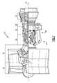
- FIG. 2shows an embodiment of an axial gearbox 200 wherein the tower shaft 70 drives a bevel gear 72 , which may be known as an input gear for purposes of this application.
- the bevel gear 72engages another bevel gear 74 .
- the bevel gear 74drives a gear 75 , and drives an accessory 76 .
- the accessory 76may be a starter, which can alternatively be driven to drive the gear 74 , and hence the tower shaft 70 .
- a startercan be arranged within such an accessory gearbox to selectively drive the tower shaft to start rotation of the turbines, fans, and compressors, and start the gas turbine engine.
- the gear 75may drive an idler gear 78 which in turn drives another gear 79 .
- Gear 79may drive an accessory 80 , which may be an integrated drive generator for generating electricity from rotation of the turbine rotors.
- a bevel gear 82rotates with the gear 79 and engages another bevel gear 84 which drives an accessory, which may be lube pump shown at 86 .
- the bevel gear 84in turn drives another bevel gear 83 which then drives a gear 90 , and drives an accessory 88 .
- the accessory 88may be a fuel pump.
- the combination of the three bevel gears 82 , 84 , 83“turns” the rotation from one side of a centerline C of the tower shaft 70 , across a diametrical envelope R of the bevel gear 72 , such that rotation is now transmitted back toward the tower shaft 70 by gear 90 being driven, and driving a gear 92 , which rotates with a gear 94 , which then ultimately drives a gear 96 .
- Gears 92 / 94drive accessory 98 , which may be a permanent magnet alternator.
- Gear 94drives gear 96 to drive accessory 100 , which may be a hydraulic pump.
- the compound gears on each shaft( 83 / 90 or 92 / 94 , for example) allows a speed change between the rotation speed of the drive for the accessories driven by the associated drive shafts.
- the gearboxmay be positioned in a smaller axial space, such that it is associated with cooler locations on the gas turbine engine, such as the compressor case.
- FIG. 3shows an alternative embodiment 300 , wherein much of the accessory drive is common to the FIG. 2 embodiment.
- the lube pump 86is driven with a bevel gear 112 which is positioned to be axially closer to the tower shaft 70 then the bevel gear 110 that drives it, and the bevel gear 114 that it drives. That is, in the FIG. 2 embodiment, the bevel gear 84 is on an opposed side of drive axes of the gears 82 and 83 relative to the tower shaft 70 , while in the FIG. 3 embodiment, the bevel gear 112 is intermediate the drive axes of the gears 110 and 114 in the tower shaft 70 . While the bevel gears as all shown with their axes of rotation at right angles to each other, other arrangements may be utilized. All that is required is the use of the bevel gears allows the drives to cross the axis of rotation of the tower shaft, and move axially along in an opposed direction.
Landscapes
- Engineering & Computer Science (AREA)
- Chemical & Material Sciences (AREA)
- Combustion & Propulsion (AREA)
- Mechanical Engineering (AREA)
- General Engineering & Computer Science (AREA)
- Gear Transmission (AREA)
Abstract
Description
Claims (20)
Priority Applications (3)
| Application Number | Priority Date | Filing Date | Title |
|---|---|---|---|
| US13/360,752US9097186B2 (en) | 2012-01-29 | 2012-01-29 | Bevel gear arrangement for axial accessory gearbox |
| EP13151438.2AEP2620622A3 (en) | 2012-01-29 | 2013-01-16 | Bevel gear arrangement for axial accessory gearbox |
| CN201310032926.4ACN103225548B (en) | 2012-01-29 | 2013-01-29 | For the bevel gear arrangements structure of axial Accessory Gear Box |
Applications Claiming Priority (1)
| Application Number | Priority Date | Filing Date | Title |
|---|---|---|---|
| US13/360,752US9097186B2 (en) | 2012-01-29 | 2012-01-29 | Bevel gear arrangement for axial accessory gearbox |
Publications (2)
| Publication Number | Publication Date |
|---|---|
| US20130193688A1 US20130193688A1 (en) | 2013-08-01 |
| US9097186B2true US9097186B2 (en) | 2015-08-04 |
Family
ID=47563228
Family Applications (1)
| Application Number | Title | Priority Date | Filing Date |
|---|---|---|---|
| US13/360,752Active2034-03-18US9097186B2 (en) | 2012-01-29 | 2012-01-29 | Bevel gear arrangement for axial accessory gearbox |
Country Status (3)
| Country | Link |
|---|---|
| US (1) | US9097186B2 (en) |
| EP (1) | EP2620622A3 (en) |
| CN (1) | CN103225548B (en) |
Families Citing this family (11)
| Publication number | Priority date | Publication date | Assignee | Title |
|---|---|---|---|---|
| US9068515B2 (en)* | 2011-12-07 | 2015-06-30 | United Technologies Corporation | Accessory gearbox with tower shaft removal capability |
| FR2995053B1 (en)* | 2012-09-03 | 2016-03-04 | Snecma | TURBOMACHINE MOVEMENT GEAR BOX COMPRISING A GEAR-LINKED CINEMA CHAIN EXTENDING IN NON-PARALLEL PLANS |
| FR3007462B1 (en)* | 2013-06-21 | 2017-11-24 | Hispano-Suiza | TURBOMACHINE ACCESSORY BOX EQUIPPED WITH CENTRIFUGAL PUMP |
| GB201610234D0 (en)* | 2016-06-13 | 2016-07-27 | Rolls Royce Plc | An accessory gearbox assembly and a gas turbine engine comprising an accessory gearbox assembly |
| US10815899B2 (en)* | 2016-11-15 | 2020-10-27 | Pratt & Whitney Canada Corp. | Gas turbine engine accessories arrangement |
| US10502142B2 (en) | 2017-04-11 | 2019-12-10 | United Technologies Corporation | Turbine engine gearbox assembly with sets of inline gears |
| GB201804577D0 (en)* | 2018-03-22 | 2018-05-09 | Rolls Royce Plc | oil/fuel pump system |
| US11261795B2 (en) | 2018-10-18 | 2022-03-01 | Rolls-Royce North American Technologies, Inc. | Dual mode starter generator |
| US11008944B2 (en) | 2018-10-18 | 2021-05-18 | Rolls-Royce North American Technologies, Inc. | Coaxial starter/generator and air turbine starter |
| FR3098240B1 (en)* | 2019-07-03 | 2021-07-16 | Safran Aircraft Engines | ARRANGEMENT OF AERONAUTICAL TURBOMACHINES INCLUDING A LUBRICATION PUMP DRIVEN BY TWO RIGHT ANGLE GEARS |
| CN114151205B (en)* | 2021-12-08 | 2022-12-27 | 中国航发南方工业有限公司 | Accessory transmission device and engine with same |
Citations (11)
| Publication number | Priority date | Publication date | Assignee | Title |
|---|---|---|---|---|
| US4287790A (en) | 1979-10-11 | 1981-09-08 | Mitsui Engineering And Shipbuilding Co., Ltd. | High-speed bevel gear transmission system |
| US5878492A (en) | 1994-06-02 | 1999-03-09 | Torvec, Inc. | Methods for shaping the teeth of spherical gears |
| US6443035B1 (en) | 2001-09-20 | 2002-09-03 | The Boeing Company | Hybrid power input quill for transmissions |
| US20050103931A1 (en) | 2003-10-27 | 2005-05-19 | Morris Timothy M. | Hybrid engine accessory power system |
| US7213488B2 (en) | 2004-01-14 | 2007-05-08 | Daniel Jeffrey K | Three way swivel divider gearbox for agricultural drive systems |
| US7500365B2 (en) | 2005-05-05 | 2009-03-10 | United Technologies Corporation | Accessory gearbox |
| US20090290976A1 (en) | 2008-05-21 | 2009-11-26 | United Technologies Corporation | Gearbox assembly |
| US7654087B2 (en) | 2003-02-24 | 2010-02-02 | Pratt & Whitney Canada Corp. | Compact compound engine package |
| US20110289936A1 (en) | 2010-05-25 | 2011-12-01 | Suciu Gabriel L | Accessory gearbox with internal layshaft |
| US8490410B2 (en)* | 2010-11-17 | 2013-07-23 | United Technologies Corporation | Axial accessory gearbox |
| US8490411B2 (en)* | 2010-11-17 | 2013-07-23 | United Technologies Corporation | Axial accessory gearbox |
Family Cites Families (5)
| Publication number | Priority date | Publication date | Assignee | Title |
|---|---|---|---|---|
| US5935038A (en)* | 1997-12-22 | 1999-08-10 | Woytaszek; Lloyd | Rotary gear drive system having bevel input gears |
| US6357220B1 (en)* | 1998-12-22 | 2002-03-19 | United Technologies Corporation | Gearbox accessory mount |
| US7805947B2 (en)* | 2005-05-19 | 2010-10-05 | Djamal Moulebhar | Aircraft with disengageable engine and auxiliary power unit components |
| CN201539536U (en)* | 2009-10-10 | 2010-08-04 | 重庆万达机电设备有限公司 | Speed increaser |
| WO2011065466A1 (en)* | 2009-11-27 | 2011-06-03 | Sato Ichiro | Rotational drive force transmission apparatus |
- 2012
- 2012-01-29USUS13/360,752patent/US9097186B2/enactiveActive
- 2013
- 2013-01-16EPEP13151438.2Apatent/EP2620622A3/ennot_activeWithdrawn
- 2013-01-29CNCN201310032926.4Apatent/CN103225548B/enactiveActive
Patent Citations (12)
| Publication number | Priority date | Publication date | Assignee | Title |
|---|---|---|---|---|
| US4287790A (en) | 1979-10-11 | 1981-09-08 | Mitsui Engineering And Shipbuilding Co., Ltd. | High-speed bevel gear transmission system |
| US5878492A (en) | 1994-06-02 | 1999-03-09 | Torvec, Inc. | Methods for shaping the teeth of spherical gears |
| US6443035B1 (en) | 2001-09-20 | 2002-09-03 | The Boeing Company | Hybrid power input quill for transmissions |
| US7654087B2 (en) | 2003-02-24 | 2010-02-02 | Pratt & Whitney Canada Corp. | Compact compound engine package |
| US20050103931A1 (en) | 2003-10-27 | 2005-05-19 | Morris Timothy M. | Hybrid engine accessory power system |
| US7213488B2 (en) | 2004-01-14 | 2007-05-08 | Daniel Jeffrey K | Three way swivel divider gearbox for agricultural drive systems |
| US7500365B2 (en) | 2005-05-05 | 2009-03-10 | United Technologies Corporation | Accessory gearbox |
| US20090290976A1 (en) | 2008-05-21 | 2009-11-26 | United Technologies Corporation | Gearbox assembly |
| US20110289936A1 (en) | 2010-05-25 | 2011-12-01 | Suciu Gabriel L | Accessory gearbox with internal layshaft |
| US8347637B2 (en)* | 2010-05-25 | 2013-01-08 | United Technologies Corporation | Accessory gearbox with internal layshaft |
| US8490410B2 (en)* | 2010-11-17 | 2013-07-23 | United Technologies Corporation | Axial accessory gearbox |
| US8490411B2 (en)* | 2010-11-17 | 2013-07-23 | United Technologies Corporation | Axial accessory gearbox |
Also Published As
| Publication number | Publication date |
|---|---|
| CN103225548A (en) | 2013-07-31 |
| EP2620622A3 (en) | 2016-11-16 |
| US20130193688A1 (en) | 2013-08-01 |
| CN103225548B (en) | 2015-08-19 |
| EP2620622A2 (en) | 2013-07-31 |
Similar Documents
| Publication | Publication Date | Title |
|---|---|---|
| US9097186B2 (en) | Bevel gear arrangement for axial accessory gearbox | |
| US11846237B2 (en) | Gas turbine engine with intercooled cooling air and dual towershaft accessory gearbox | |
| EP3354881B1 (en) | Gas turbine engine dual towershaft accessory gearbox and starter generator assembly | |
| US10393028B1 (en) | Geared compressor for gas turbine engine | |
| EP3282093B1 (en) | Geared turbofan with low spool power extraction | |
| US10352250B2 (en) | Equipment support of a turbo machine comprising a reducer with magnetic gears | |
| US11248532B2 (en) | Hybrid electric dual spool power extraction gearbox | |
| US8973465B2 (en) | Gearbox for gas turbine engine | |
| US10605173B2 (en) | High and low spool accessory gearbox drive | |
| US10526976B2 (en) | Tangential drive for gas turbine engine accessories | |
| US20150152783A1 (en) | Combination of two gas turbines to drive a load | |
| US20160258356A1 (en) | Gas turbine engine with magnetic gearbox | |
| US20160333793A1 (en) | Accessory gearbox assembly for an aircraft turbine engine | |
| US12215631B2 (en) | Turbomachine module equipped with an electric machine, and turbomachine equipped with such a module | |
| US12203539B2 (en) | Compact accessory gearbox comprising an integrated electric machine |
Legal Events
| Date | Code | Title | Description |
|---|---|---|---|
| AS | Assignment | Owner name:UNITED TECHNOLOGIES CORPORATION, CONNECTICUT Free format text:ASSIGNMENT OF ASSIGNORS INTEREST;ASSIGNORS:DUONG, HUNG;SUCIU, GABRIEL L.;DYE, CHRISTOPHER M.;SIGNING DATES FROM 20120123 TO 20120124;REEL/FRAME:027613/0352 | |
| STCF | Information on status: patent grant | Free format text:PATENTED CASE | |
| MAFP | Maintenance fee payment | Free format text:PAYMENT OF MAINTENANCE FEE, 4TH YEAR, LARGE ENTITY (ORIGINAL EVENT CODE: M1551); ENTITY STATUS OF PATENT OWNER: LARGE ENTITY Year of fee payment:4 | |
| AS | Assignment | Owner name:RAYTHEON TECHNOLOGIES CORPORATION, MASSACHUSETTS Free format text:CHANGE OF NAME;ASSIGNOR:UNITED TECHNOLOGIES CORPORATION;REEL/FRAME:054062/0001 Effective date:20200403 | |
| AS | Assignment | Owner name:RAYTHEON TECHNOLOGIES CORPORATION, CONNECTICUT Free format text:CORRECTIVE ASSIGNMENT TO CORRECT THE AND REMOVE PATENT APPLICATION NUMBER 11886281 AND ADD PATENT APPLICATION NUMBER 14846874. TO CORRECT THE RECEIVING PARTY ADDRESS PREVIOUSLY RECORDED AT REEL: 054062 FRAME: 0001. ASSIGNOR(S) HEREBY CONFIRMS THE CHANGE OF ADDRESS;ASSIGNOR:UNITED TECHNOLOGIES CORPORATION;REEL/FRAME:055659/0001 Effective date:20200403 | |
| MAFP | Maintenance fee payment | Free format text:PAYMENT OF MAINTENANCE FEE, 8TH YEAR, LARGE ENTITY (ORIGINAL EVENT CODE: M1552); ENTITY STATUS OF PATENT OWNER: LARGE ENTITY Year of fee payment:8 | |
| AS | Assignment | Owner name:RTX CORPORATION, CONNECTICUT Free format text:CHANGE OF NAME;ASSIGNOR:RAYTHEON TECHNOLOGIES CORPORATION;REEL/FRAME:064714/0001 Effective date:20230714 |