US9097061B1 - Window sash pivot bar - Google Patents
Window sash pivot barDownload PDFInfo
- Publication number
- US9097061B1 US9097061B1US13/804,060US201313804060AUS9097061B1US 9097061 B1US9097061 B1US 9097061B1US 201313804060 AUS201313804060 AUS 201313804060AUS 9097061 B1US9097061 B1US 9097061B1
- Authority
- US
- United States
- Prior art keywords
- shield
- elongated member
- vertical
- pivot bar
- sash
- Prior art date
- Legal status (The legal status is an assumption and is not a legal conclusion. Google has not performed a legal analysis and makes no representation as to the accuracy of the status listed.)
- Active
Links
Images


Classifications
- E—FIXED CONSTRUCTIONS
- E05—LOCKS; KEYS; WINDOW OR DOOR FITTINGS; SAFES
- E05D—HINGES OR SUSPENSION DEVICES FOR DOORS, WINDOWS OR WINGS
- E05D5/00—Construction of single parts, e.g. the parts for attachment
- E—FIXED CONSTRUCTIONS
- E06—DOORS, WINDOWS, SHUTTERS, OR ROLLER BLINDS IN GENERAL; LADDERS
- E06B—FIXED OR MOVABLE CLOSURES FOR OPENINGS IN BUILDINGS, VEHICLES, FENCES OR LIKE ENCLOSURES IN GENERAL, e.g. DOORS, WINDOWS, BLINDS, GATES
- E06B3/00—Window sashes, door leaves, or like elements for closing wall or like openings; Layout of fixed or moving closures, e.g. windows in wall or like openings; Features of rigidly-mounted outer frames relating to the mounting of wing frames
- E06B3/32—Arrangements of wings characterised by the manner of movement; Arrangements of movable wings in openings; Features of wings or frames relating solely to the manner of movement of the wing
- E06B3/50—Arrangements of wings characterised by the manner of movement; Arrangements of movable wings in openings; Features of wings or frames relating solely to the manner of movement of the wing with more than one kind of movement
- E06B3/5054—Arrangements of wings characterised by the manner of movement; Arrangements of movable wings in openings; Features of wings or frames relating solely to the manner of movement of the wing with more than one kind of movement where the sliding and rotating movements are independent of each other
- E06B3/5063—Arrangements of wings characterised by the manner of movement; Arrangements of movable wings in openings; Features of wings or frames relating solely to the manner of movement of the wing with more than one kind of movement where the sliding and rotating movements are independent of each other the vertical sliding wings having the possibility of an additional rotational movement
- E—FIXED CONSTRUCTIONS
- E05—LOCKS; KEYS; WINDOW OR DOOR FITTINGS; SAFES
- E05D—HINGES OR SUSPENSION DEVICES FOR DOORS, WINDOWS OR WINGS
- E05D15/00—Suspension arrangements for wings
- E—FIXED CONSTRUCTIONS
- E05—LOCKS; KEYS; WINDOW OR DOOR FITTINGS; SAFES
- E05D—HINGES OR SUSPENSION DEVICES FOR DOORS, WINDOWS OR WINGS
- E05D15/00—Suspension arrangements for wings
- E05D15/16—Suspension arrangements for wings for wings sliding vertically more or less in their own plane
- E05D15/22—Suspension arrangements for wings for wings sliding vertically more or less in their own plane allowing an additional movement
- E—FIXED CONSTRUCTIONS
- E05—LOCKS; KEYS; WINDOW OR DOOR FITTINGS; SAFES
- E05D—HINGES OR SUSPENSION DEVICES FOR DOORS, WINDOWS OR WINGS
- E05D7/00—Hinges or pivots of special construction
- E05D7/06—Hinges or pivots of special construction to allow tilting of the members
- E—FIXED CONSTRUCTIONS
- E05—LOCKS; KEYS; WINDOW OR DOOR FITTINGS; SAFES
- E05D—HINGES OR SUSPENSION DEVICES FOR DOORS, WINDOWS OR WINGS
- E05D2700/00—Hinges or other suspension devices especially for doors or windows
- E05D2700/10—Various door and window fittings, e.g. suspension devices for double hung windows or screens
- E—FIXED CONSTRUCTIONS
- E05—LOCKS; KEYS; WINDOW OR DOOR FITTINGS; SAFES
- E05Y—INDEXING SCHEME ASSOCIATED WITH SUBCLASSES E05D AND E05F, RELATING TO CONSTRUCTION ELEMENTS, ELECTRIC CONTROL, POWER SUPPLY, POWER SIGNAL OR TRANSMISSION, USER INTERFACES, MOUNTING OR COUPLING, DETAILS, ACCESSORIES, AUXILIARY OPERATIONS NOT OTHERWISE PROVIDED FOR, APPLICATION THEREOF
- E05Y2201/00—Constructional elements; Accessories therefor
Definitions
- the invention hereinpertains to tilt type window sashes and particularly pertains to a pivot bar which can be quickly mounted on-site during window installation.
- tiltable double hung window sashesallow the home owner or others to tilt the sashes inwardly on the window frames for cleaning, maintenance and the like.
- Such tilt window sashesutilize various mechanisms including axles, rods and the like to provide an axis for rotation. While certain of the prior art devices functioned well in use, the installation and assembly was quite complex and often could not be performed on-site with ordinary work tools.
- the present inventionwas conceived and one of its objectives is to provide a pivot bar for use on window sashes which can be easily and quickly installed on site.
- a pivot bar and method of installation for double hung and other windows which have tilting sashesWindow components are generally manufactured at a factory for assembly and installation in homes and other buildings.
- Conventional tilt sash windowsemploy a rod or other mechanical device to allow the sash to pivot.
- a pivot bar as shown hereincan be used which includes an elongated member having a distal tapered end and a proximal blunt or knob end.
- Top and bottom shields attached to the elongated memberclose and seal the openings formed in the window sash for insertion therein.
- a desired sashis selected for a particular window.
- An electric drill or similar toolis then used to simultaneously bore an opening in the side and bottom of the sash stile.
- the openinghas a center point slightly above the bottom edge of the stile to allow the drill bit to form an arcuate opening in the side of the stile.
- This arcuate openingis not fully circular as the bottom portion of the bit is below the stile and simultaneously cuts an opening in the bottom of the sash perpendicular to the side.
- the pivot barcan then be inserted into the opening with the vertical shield sealing the arcuate opening in the stile side while the bottom shield seals the opening along the bottom of the sash.
- An adhesive or caulkcan be applied if necessary for a thorough seal of the shields to the stile and sash. As needed, an additional hole is provided in the bottom shield for use in attachment of the sash with a screw. An identical opening is drilled in the opposite side of the sash and the installation is repeated for a second pivot bar. The installation is quick and easy as the sash pivot bars are placed into grooves on each side of the window jamb and easily slide in place for the necessary tilting action.
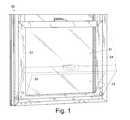
- FIG. 1shows a perspective view of a lower tiltable sash of a double hung window seen in fragmented fashion
- FIG. 2pictures the sash of FIG. 1 removed from the window frame during schematic pivot bar installation
- FIG. 3depicts a partial side elevational view of the stile seen in FIG. 2 with the opening formed for pivot bar insertion;
- FIG. 4demonstrates a bottom view of the partial sash seen in FIG. 3 ;
- FIG. 5features an elevational view of the partial stile of FIG. 3 with the pivot bar installed
- FIG. 6illustrates a perspective view of the preferred form of the pivot bar
- FIG. 7shows a rear elevational view of the pivot bar seen in FIG. 6 ;
- FIG. 8illustrates a front elevational view of the pivot bar as seen in FIG. 6 ;
- FIG. 9depicts a top plan view of the pivot bar shown in FIG. 6 ;
- FIG. 10demonstrates a bottom plan view of the partial sash with the pivot bar as seen in FIG. 6 installed therein;
- FIG. 11pictures a cut-away side elevational view of the pivot bar as installed in a window sash.
- FIG. 1illustrates a partial conventional double hung window 50 with lower sash 51 shown in both normal (vertical) and tilted (dashed line) positions.
- preferred pivot bars 10 , 10 ′as seen in FIG. 2 are employed in stiles 52 , 52 ′ of sash 51 .
- FIG. 2demonstrates schematically, drill 40 which is a standard electric drill having removable bit 41 used to form opening 11 .
- Sash 51is shown prior to installation in window frame 54 having stiles 52 , 52 ′ and sash bottom 53 which as understood are each hollow.
- the method of installationincludes the selection of a drill bit 41 which is appropriately sized for use with sash 51 depending on the structural materials such as wood, aluminum or plastics such as polymeric compositions.
- pivot bar opening 11as shown in FIGS. 2 and 3 may be for example 13/16 inches in diameter with the width of stile 52 being 13 ⁇ 4 inches.
- opening 11is not a complete circle as the center C is slightly above the bottom edge 59 of stile 52 .
- drill bit 41simultaneously cuts opening 11 in stile 52 and channel 12 in sash bottom 53 as seen in FIG. 4 . In this manner, the front wall of stile 52 and the bottom wall of sash bottom 53 are cut simultaneously for easy installation of preferred pivot bar 10 .
- FIG. 5demonstrates the installation of preferred pivot bar 10 in opening 11 and channel 12 of sash 51 .
- Pivot bar 10 as shown in FIG. 6includes longitudinal member 14 having a terminal tapered end 15 with knob 16 ( FIG. 7 ) on the proximal end.
- Vertical planar shield 17is positioned perpendicular to longitudinal axis A as seen in FIG. 11 of longitudinal member 14 proximate knob 16 and is affixed to support 19 .
- Horizontal shield 18is parallel to longitudinal axis A of longitudinal member 14 and is attached to support 19 .
- Support 19is L-shaped as shown in FIG. 11 and approximates the thickness of the wall thickness of stile 52 as seen in FIG. 11 .
- Vertical shield 17is U-shaped and sized to completely cover opening 11 in stile 52 whereas horizontal shield 18 has an elongated U-shape and is sized to completely cover channel 12 formed in sash bottom 53 as seen in FIG. 10 .
- Elongated member 14 as seen in FIGS. 8 and 9further includes horizontal ribs 13 and vertical ribs 13 ′ which extend slightly beyond support 19 as shown in FIG. 11 , towards knob 16 .
- Ribs 13 , 13 ′are tapered and are slightly larger than opening 11 to allow them to “snap” into place over the rear of the front wall of stile 52 while tightly securing pivot bar 10 during installation.
- channel 12as shown in dotted line fashion in FIG.
- pivot bar 10as seen in FIGS. 5-11 can be easily installed on-site in a window sash using conventional tools by those of relatively low skill. Once both pivot bars 10 , 10 ′ are installed, sash 51 can be inserted into a window frame such as window frame 54 whereby knobs 16 , 16 ′ ( 16 ′ not shown) are then placed in preformed slots or grooves in the window jambs as conventional to allow for tilting of sash 51 .
Landscapes
- Engineering & Computer Science (AREA)
- Mechanical Engineering (AREA)
- Civil Engineering (AREA)
- Structural Engineering (AREA)
- Wing Frames And Configurations (AREA)
- Specific Sealing Or Ventilating Devices For Doors And Windows (AREA)
Abstract
Description
Claims (7)
Priority Applications (2)
| Application Number | Priority Date | Filing Date | Title |
|---|---|---|---|
| US13/804,060US9097061B1 (en) | 2013-03-14 | 2013-03-14 | Window sash pivot bar |
| US14/740,905US9435150B1 (en) | 2013-03-14 | 2015-06-16 | Window sash pivot bar and method |
Applications Claiming Priority (1)
| Application Number | Priority Date | Filing Date | Title |
|---|---|---|---|
| US13/804,060US9097061B1 (en) | 2013-03-14 | 2013-03-14 | Window sash pivot bar |
Related Child Applications (1)
| Application Number | Title | Priority Date | Filing Date |
|---|---|---|---|
| US14/740,905ContinuationUS9435150B1 (en) | 2013-03-14 | 2015-06-16 | Window sash pivot bar and method |
Publications (1)
| Publication Number | Publication Date |
|---|---|
| US9097061B1true US9097061B1 (en) | 2015-08-04 |
Family
ID=53718860
Family Applications (2)
| Application Number | Title | Priority Date | Filing Date |
|---|---|---|---|
| US13/804,060ActiveUS9097061B1 (en) | 2013-03-14 | 2013-03-14 | Window sash pivot bar |
| US14/740,905ActiveUS9435150B1 (en) | 2013-03-14 | 2015-06-16 | Window sash pivot bar and method |
Family Applications After (1)
| Application Number | Title | Priority Date | Filing Date |
|---|---|---|---|
| US14/740,905ActiveUS9435150B1 (en) | 2013-03-14 | 2015-06-16 | Window sash pivot bar and method |
Country Status (1)
| Country | Link |
|---|---|
| US (2) | US9097061B1 (en) |
Cited By (6)
| Publication number | Priority date | Publication date | Assignee | Title |
|---|---|---|---|---|
| US20160123048A1 (en)* | 2014-10-30 | 2016-05-05 | Caldwell Manufacturing Company North America, LLC | Pivot Bar For Window Sash |
| US20160228315A1 (en)* | 2015-02-06 | 2016-08-11 | Mizuho Orthopedic Systems, Inc. | Surgery table attachment apparatus |
| US9435150B1 (en)* | 2013-03-14 | 2016-09-06 | Barry G. Lawrence | Window sash pivot bar and method |
| US10888481B2 (en) | 2015-02-04 | 2021-01-12 | Mizuho Orthopedic Systems, Inc. | Adjustable support apparatus for a surgery table |
| US11536082B2 (en)* | 2020-09-18 | 2022-12-27 | Jeld-Wen, Inc. | Pivot bar for sash windows |
| US11549293B1 (en)* | 2019-11-12 | 2023-01-10 | Barry G. Lawrence | Threaded pivot bar and method |
Citations (7)
| Publication number | Priority date | Publication date | Assignee | Title |
|---|---|---|---|---|
| US4926524A (en)* | 1987-08-31 | 1990-05-22 | Owens George W | Window pivot corner |
| US5069001A (en)* | 1990-11-21 | 1991-12-03 | Insul-Lite Window Manufacturing, Inc. | Pivotable window sash assembly |
| US5704165A (en)* | 1996-07-19 | 1998-01-06 | Csb Enterprises, Inc. | Pivotable window sash assembly |
| US6058653A (en)* | 1996-07-19 | 2000-05-09 | Csb Enterprise, Inc. | Pivotable window sash assembly |
| US20030121207A1 (en)* | 2001-02-09 | 2003-07-03 | Ashland Products, Inc. | Brake shoe for sash window or door assembly |
| US6658794B1 (en)* | 2000-02-23 | 2003-12-09 | Newell Operating Company | Guide assembly for a tilt-out sash window |
| US6857228B2 (en)* | 2003-04-18 | 2005-02-22 | John Evans Sons, Inc | Counterbalance system for a tilt-in window |
Family Cites Families (5)
| Publication number | Priority date | Publication date | Assignee | Title |
|---|---|---|---|---|
| US5669180A (en)* | 1996-05-29 | 1997-09-23 | Ro Mai Ind Inc | Window balance brake shoe and pivot assembly |
| US5927013A (en)* | 1996-07-19 | 1999-07-27 | Csb Enterprises, Inc. | Pivotable window sash assembly |
| US8020904B2 (en)* | 2001-11-07 | 2011-09-20 | Newell Operating Company | Integrated tilt/sash lock assembly |
| US20040206003A1 (en)* | 2003-04-18 | 2004-10-21 | Kunz John R. | Window sash counterbalance and position locking system for a tilt-in window |
| US9097061B1 (en)* | 2013-03-14 | 2015-08-04 | Barry G. Lawrence | Window sash pivot bar |
- 2013
- 2013-03-14USUS13/804,060patent/US9097061B1/enactiveActive
- 2015
- 2015-06-16USUS14/740,905patent/US9435150B1/enactiveActive
Patent Citations (7)
| Publication number | Priority date | Publication date | Assignee | Title |
|---|---|---|---|---|
| US4926524A (en)* | 1987-08-31 | 1990-05-22 | Owens George W | Window pivot corner |
| US5069001A (en)* | 1990-11-21 | 1991-12-03 | Insul-Lite Window Manufacturing, Inc. | Pivotable window sash assembly |
| US5704165A (en)* | 1996-07-19 | 1998-01-06 | Csb Enterprises, Inc. | Pivotable window sash assembly |
| US6058653A (en)* | 1996-07-19 | 2000-05-09 | Csb Enterprise, Inc. | Pivotable window sash assembly |
| US6658794B1 (en)* | 2000-02-23 | 2003-12-09 | Newell Operating Company | Guide assembly for a tilt-out sash window |
| US20030121207A1 (en)* | 2001-02-09 | 2003-07-03 | Ashland Products, Inc. | Brake shoe for sash window or door assembly |
| US6857228B2 (en)* | 2003-04-18 | 2005-02-22 | John Evans Sons, Inc | Counterbalance system for a tilt-in window |
Cited By (8)
| Publication number | Priority date | Publication date | Assignee | Title |
|---|---|---|---|---|
| US9435150B1 (en)* | 2013-03-14 | 2016-09-06 | Barry G. Lawrence | Window sash pivot bar and method |
| US20160123048A1 (en)* | 2014-10-30 | 2016-05-05 | Caldwell Manufacturing Company North America, LLC | Pivot Bar For Window Sash |
| US9982469B2 (en)* | 2014-10-30 | 2018-05-29 | Caldwell Manufacturing Company North America, LLC | Pivot bar for window sash |
| US10888481B2 (en) | 2015-02-04 | 2021-01-12 | Mizuho Orthopedic Systems, Inc. | Adjustable support apparatus for a surgery table |
| US20160228315A1 (en)* | 2015-02-06 | 2016-08-11 | Mizuho Orthopedic Systems, Inc. | Surgery table attachment apparatus |
| US9713562B2 (en)* | 2015-02-06 | 2017-07-25 | Mizuho Orthopedic Systems, Inc. | Surgery table attachment apparatus |
| US11549293B1 (en)* | 2019-11-12 | 2023-01-10 | Barry G. Lawrence | Threaded pivot bar and method |
| US11536082B2 (en)* | 2020-09-18 | 2022-12-27 | Jeld-Wen, Inc. | Pivot bar for sash windows |
Also Published As
| Publication number | Publication date |
|---|---|
| US9435150B1 (en) | 2016-09-06 |
Similar Documents
| Publication | Publication Date | Title |
|---|---|---|
| US9435150B1 (en) | Window sash pivot bar and method | |
| JP5946869B2 (en) | Outer wall mounting member and outer wall structure | |
| US9598892B2 (en) | Quick release cladding system for door, window, sloped and vertical glazing systems frames, and the like | |
| US3514904A (en) | Adjustable handle for sliding sash | |
| US11536082B2 (en) | Pivot bar for sash windows | |
| US11993956B2 (en) | Sliding door foot bolt | |
| EP2145070A2 (en) | Pane having two adhesion planes | |
| DE19931171A1 (en) | Window system with a window pane that has at least two glass panes and a hardware groove | |
| JP5036067B2 (en) | sash | |
| EP1510644A3 (en) | Window or door construction | |
| AU2014227553A1 (en) | Double hung window assembly | |
| JP5841927B2 (en) | Joinery | |
| EP3597850B1 (en) | Apparatus for making and mounting a sliding panel for doors and windows | |
| DE19855241A1 (en) | Method for fastening a frame using an assembly frame | |
| EP3389459B1 (en) | Shower enclosure header | |
| DE102010035346B4 (en) | Concealed thermally separated wooden / metal sash frame | |
| DE29905777U1 (en) | Burglar-resistant window or burglar-resistant door | |
| EP4202170B1 (en) | Connector, butt joint, and method for manufacturing same | |
| GB2524100A (en) | Sash hardware locating system and method | |
| JP2018178458A (en) | Frame attachment mounting structure | |
| EP4234876A1 (en) | A method for installing a sunshade in a light opening of a building element, and a building element | |
| JPH0145350Y2 (en) | ||
| DE10138052B4 (en) | Window frames with window fittings | |
| DE10229235A1 (en) | Constructional element for window or outer door in building has hollow profile with guide rails and roller for mosquito screen and roller door | |
| EP1640547A1 (en) | A method of attaching a cover element to a window casement, and a cover element to be attached to a window casement |
Legal Events
| Date | Code | Title | Description |
|---|---|---|---|
| STCF | Information on status: patent grant | Free format text:PATENTED CASE | |
| MAFP | Maintenance fee payment | Free format text:PAYMENT OF MAINTENANCE FEE, 4TH YR, SMALL ENTITY (ORIGINAL EVENT CODE: M2551); ENTITY STATUS OF PATENT OWNER: SMALL ENTITY Year of fee payment:4 | |
| MAFP | Maintenance fee payment | Free format text:PAYMENT OF MAINTENANCE FEE, 8TH YR, SMALL ENTITY (ORIGINAL EVENT CODE: M2552); ENTITY STATUS OF PATENT OWNER: SMALL ENTITY Year of fee payment:8 | |
| AS | Assignment | Owner name:AMESBURY INDUSTRIES, INC., MINNESOTA Free format text:ASSIGNMENT OF ASSIGNORS INTEREST;ASSIGNOR:LAWRENCE, RANDY;REEL/FRAME:066572/0063 Effective date:20230721 Owner name:AMESBURY INDUSTRIES, INC., MINNESOTA Free format text:ASSIGNMENT OF ASSIGNORS INTEREST;ASSIGNOR:LAWRENCE, BARRY G.;REEL/FRAME:066572/0013 Effective date:20230712 Owner name:AMESBURY INDUSTRIES, INC., MINNESOTA Free format text:ASSIGNMENT OF ASSIGNORS INTEREST;ASSIGNOR:LAWRENCE, BRANDON;REEL/FRAME:066571/0923 Effective date:20230712 | |
| FEPP | Fee payment procedure | Free format text:ENTITY STATUS SET TO UNDISCOUNTED (ORIGINAL EVENT CODE: BIG.); ENTITY STATUS OF PATENT OWNER: LARGE ENTITY |