US9096913B2 - Process and system for creating internal stress in a metallic workpiece - Google Patents
Process and system for creating internal stress in a metallic workpieceDownload PDFInfo
- Publication number
- US9096913B2 US9096913B2US12/275,668US27566808AUS9096913B2US 9096913 B2US9096913 B2US 9096913B2US 27566808 AUS27566808 AUS 27566808AUS 9096913 B2US9096913 B2US 9096913B2
- Authority
- US
- United States
- Prior art keywords
- plasma
- laser
- workpiece
- process according
- laser pulse
- Prior art date
- Legal status (The legal status is an assumption and is not a legal conclusion. Google has not performed a legal analysis and makes no representation as to the accuracy of the status listed.)
- Active, expires
Links
- 238000000034methodMethods0.000titleclaimsabstractdescription39
- 230000008569processEffects0.000titleclaimsabstractdescription39
- 239000010410layerSubstances0.000claimsabstractdescription19
- 239000002344surface layerSubstances0.000claimsabstractdescription16
- 230000035939shockEffects0.000claimsabstractdescription15
- XLYOFNOQVPJJNP-UHFFFAOYSA-NwaterSubstancesOXLYOFNOQVPJJNP-UHFFFAOYSA-N0.000claimsabstractdescription5
- 230000015572biosynthetic processEffects0.000claimsdescription9
- 239000002184metalSubstances0.000claimsdescription7
- 239000011248coating agentSubstances0.000claimsdescription3
- 238000000576coating methodMethods0.000claimsdescription3
- 239000011888foilSubstances0.000claimsdescription3
- 239000011368organic materialSubstances0.000claimsdescription3
- 230000008020evaporationEffects0.000description7
- 238000001704evaporationMethods0.000description7
- 230000000694effectsEffects0.000description6
- 230000005855radiationEffects0.000description5
- 230000006698inductionEffects0.000description4
- 238000002679ablationMethods0.000description3
- 238000003754machiningMethods0.000description3
- 238000006243chemical reactionMethods0.000description2
- 230000005284excitationEffects0.000description2
- 238000004519manufacturing processMethods0.000description2
- 239000000463materialSubstances0.000description2
- 230000001052transient effectEffects0.000description2
- 238000010521absorption reactionMethods0.000description1
- 230000009471actionEffects0.000description1
- 230000008859changeEffects0.000description1
- 230000006835compressionEffects0.000description1
- 238000007906compressionMethods0.000description1
- 230000007797corrosionEffects0.000description1
- 238000005260corrosionMethods0.000description1
- 230000002349favourable effectEffects0.000description1
- 238000010438heat treatmentMethods0.000description1
- 230000036540impulse transmissionEffects0.000description1
- 239000007769metal materialSubstances0.000description1
- 238000012986modificationMethods0.000description1
- 230000004048modificationEffects0.000description1
- 238000007711solidificationMethods0.000description1
- 230000008023solidificationEffects0.000description1
- 239000000126substanceSubstances0.000description1
Images

Classifications
- C—CHEMISTRY; METALLURGY
- C21—METALLURGY OF IRON
- C21D—MODIFYING THE PHYSICAL STRUCTURE OF FERROUS METALS; GENERAL DEVICES FOR HEAT TREATMENT OF FERROUS OR NON-FERROUS METALS OR ALLOYS; MAKING METAL MALLEABLE, e.g. BY DECARBURISATION OR TEMPERING
- C21D10/00—Modifying the physical properties by methods other than heat treatment or deformation
- C21D10/005—Modifying the physical properties by methods other than heat treatment or deformation by laser shock processing
Definitions
- the inventionrelates to a process and a system for creating internal stress in a metallic workpiece by laser shock peening (LSP).
- LSPlaser shock peening
- Laser shock peeningis a process by which internal stress can be created in a metallic workpiece with a pulsed laser beam. Internal stress in the metallic workpiece is often desired because it can prevent fatigue or crack propagation when the workpiece is loaded.
- the material to be treatedis acted upon by an ablative surface layer before laser shock peening.
- the surface layeris formed, for example, by a metal coating, a metal foil or is made of organic materials.
- the surface layerevaporates and is changed into the plasma condition (state of ionization).
- a covering layeris generated over the treatment site, which covering layer is formed, for example, by flowing water. This covering layer contributes to the fact that the transient plasma formed by the effect of the laser beam on the surface layer is spatially fixed for a time period corresponding approximately to the pulse duration.
- the laser pulse with an energy of, for example, 5 to 50 Jis used for the evaporation of the surface layer as well as for the plasma formation.
- the used laser beamsconventionally have a pulse duration of from 10 to 50 nanoseconds (nsecs).
- such a laser impulseis applied to the workpiece at various sites in a spatially offset, simultaneous or time-staggered manner in that, for example, the workpiece and the laser generating device are moved relative to one another and, in each case, identical laser impulses act upon various sites on the workpiece.
- a single laser pulsealways acts upon one site, which laser pulse is sufficiently energetic (by controlling the laser pulse energy as well as the pulse duration) that it results in the production and propagation of the plasma and that the induced solid-state shock wave has a sufficiently high shock intensity so that the plastic yield point in the workpiece is exceeded and internal stress is thereby created in the metallic workpiece.
- the processis used mainly for creating compressive internal stress on surface areas, i.e., in depths of up to 10 mm, for protecting against stress crack corrosion but also for the purpose of deformation.
- one object of the inventionto provide a process and a device system for creating internal stress in a metallic workpiece using laser shock peening (LSP), which process improves the utilization of the energy of the laser beam and thereby results in more targeted and stronger shock waves in the workpiece, which shock waves, in turn, cause the induction of internal stress.
- LSPlaser shock peening
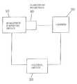
- FIGUREshows a system according to certain embodiments of the invention.
- a first laser pulseis applied to a treatment site of the workpiece covered by a surface layer.
- a second laser pulsewhich is time staggered relative to the first laser pulse, is applied to the treatment site of the workpiece.
- a covering layer over the treatment site during the application of the laser pulsesis provided.
- FIG. 1depicts an embodiment of a system including a workpiece stressing device 10 is provided by the invention.
- the systemincludes at least one laser 20 and a control device 30 for controlling the relative movement between a clamped-in workpiece 40 and the laser 20 .
- the control device 30is adapted for controlling the process using different embodiments of the invention.
- An objective of the inventioninvolves applying to one and the same treatment site of the workpiece at least two time-staggered laser pulses, as required, with a short pause without any laser pulse action between the staggered laser pulses.
- the energy fed by the laser beamcan be adjusted in a targeted manner to the physical processes occurring in the surface layer so that, for example, the first pulse causes the evaporation or ablation of the absorbing layer and a pre-plasma is formed which has a low ionization.
- the second laser pulsecan be controlled in such a manner energetically that it causes the formation of a fully developed, quasi-static plasma, which is a non-balanced state with high ionization, and also leads to the expansion of the plasma through the covering layer and thereby to the induction of internal stress in the workpiece.
- the time-staggered laser pulses affecting the same treatment siteare preferably characterized by different energy.
- the second pulsepreferably is significantly higher with respect to energy than the first pulse.
- the first pulsecan be a low energy pulse.
- This first pulsecauses the evaporation, for which a significantly lower energy is required than for the subsequent formation and expansion of an unsteady plasma with a comparatively high enthalpy.
- the relatively high energy of the second laser pulsewhich is required for the later conversion of the plasma energy to predominantly energetic flow enthalpy, is utilized very well and is predominantly used for the conversion and expansion process of the unsteady plasma, without the occurrence of massive radiation losses or considerable (unnecessary) temperature increases.
- the laser pulse intended for the formation and expansion of the unsteady plasmashould have relatively high energy.
- the evaporation process and the plasma heating processare thereby uncoupled with respect to time, so that the energetic utilization of the laser impulses is improved and the effect on the workpiece is more targeted.
- the slightly ionized primary plasmais produced by an, at first, relatively moderate energy use.
- this primary plasma conditionhas a high absorption capacity for the radiation of the secondary laser pulse, so that a much higher fraction of the incident laser radiation can be effectively converted to plasma enthalpy than is possible in the case of a conventional single-pulse excitation.
- the resulting losses by reflection, the passage of the laser pulses in an unutilized manner to the metal surface by way of an initially optically thin plasma as well as by convention and also radiationcan thereby be minimized.
- the interval between laser pulsesis, for example, 5 to 100 nsecs.
- the laser pulsescan immediately, i.e., without any time-related staggering, follow one another.
- it is preferred to provide a time period of from 5 to 100 nsecs between the laser pulsesbecause then, as a result of a corresponding coordination of the laser pulses, as well as of the time interval and the number of laser pulses, a targeted effect can be achieved on the individual processes occurring during the formation of the plasma and in the plasma.
- Each laser pulsecan be adapted to a certain condition of the plasma.
- the pulse forms of the time-staggered laser pulsesare also different.
- the laser pulsespreferably have different leading-edge shapes.
- the selection of a suitable leading edgemay also have a targeted effect on the energetic processes.
- the different energetic conditions of the laser pulses having a staggered effectare generated by their time-related width and/or energy.
- more than two time-staggered laser pulsesare applied to the same treatment site and have their effect there. In this case, the energetic control is even more favorable.
- flowing watercan be used as a covering layer.
- the time-staggered laser pulsescan be provided by a single laser or by a laser that differs for each laser pulse. Especially in the case of the preferred use of several machining lasers, it is easily possible to represent different pulse forms, different energies for the pulses, etc., for generating the staggered laser pulses. However, even when several machining lasers are used, these act upon the same machining site at the workpiece in a time-staggered manner.
- the processwhich preferably also contains the step of applying the surface layer to be evaporated before the first laser pulse is applied, which surface layer is produced, for example, by metal coating, application of a metal foil or application of organic material, as required and depending on the workpiece into which the internal stress is to be entered or on which the deformation is to be generated, can be repeated at several sites of the workpiece in order to achieve, for example, a larger-surface solidification, in which case, however, a double or multiple pulse acts upon each site.
- a primary plasma enthalpybe achieved that is as high as possible for a time period in which the plasma is largely stabilized by the covering layer, such as flowing water.
- Use of a single laser pulseis not optimal for the evaporation of the ablation material in addition to producing a transient high-pressure plasma (with peak pressures of up to over 10 bar), because of energy requirement differentials for the evaporation and primary plasma production, when compared with the subsequent formation of an unsteady plasma with a comparatively high enthalpy.
- This processis more effective with the higher original enthalpy (defined by pressure and temperature) of the primary plasma, and its ability to be changed to kinetic flow enthalpy, which takes place in the phase of the expanding and rapidly flowing plasma breaching the covering layer.
- the individual processes during laser shock peeningcomprise the stages of primary evaporation (ablation) of the absorbing layer; formation of a pre-plasma that is slightly ionized, formation of a fully formed, quasi-static plasma which is an unbalanced condition with a high ionization, and expansion of the plasma through the covering layer.
- ablationprimary evaporation
Landscapes
- Chemical & Material Sciences (AREA)
- Physics & Mathematics (AREA)
- Engineering & Computer Science (AREA)
- Optics & Photonics (AREA)
- Thermal Sciences (AREA)
- Crystallography & Structural Chemistry (AREA)
- Mechanical Engineering (AREA)
- Materials Engineering (AREA)
- Metallurgy (AREA)
- Organic Chemistry (AREA)
- Laser Beam Processing (AREA)
Abstract
Description
Claims (17)
Applications Claiming Priority (3)
| Application Number | Priority Date | Filing Date | Title |
|---|---|---|---|
| DE102007056502.1 | 2007-11-22 | ||
| DE200710056502DE102007056502B4 (en) | 2007-11-22 | 2007-11-22 | Method and device for building up residual stresses in a metallic workpiece |
| DE102007056502 | 2007-11-22 |
Publications (2)
| Publication Number | Publication Date |
|---|---|
| US20090134130A1 US20090134130A1 (en) | 2009-05-28 |
| US9096913B2true US9096913B2 (en) | 2015-08-04 |
Family
ID=40364337
Family Applications (1)
| Application Number | Title | Priority Date | Filing Date |
|---|---|---|---|
| US12/275,668Active2032-07-31US9096913B2 (en) | 2007-11-22 | 2008-11-21 | Process and system for creating internal stress in a metallic workpiece |
Country Status (3)
| Country | Link |
|---|---|
| US (1) | US9096913B2 (en) |
| EP (1) | EP2065477B1 (en) |
| DE (1) | DE102007056502B4 (en) |
Families Citing this family (3)
| Publication number | Priority date | Publication date | Assignee | Title |
|---|---|---|---|---|
| WO2011037597A1 (en) | 2009-09-23 | 2011-03-31 | Pratt & Whitney Rocketdyne, Inc. | A system and method of combustion for sustaining a continuous detonation wave with transient plasma |
| CN105935769B (en)* | 2016-07-07 | 2017-11-28 | 四川三阳激光增材制造技术有限公司 | A kind of laser melting coating for 3D printing drip molding etches preparation method |
| CN110361121B (en)* | 2018-04-09 | 2020-12-25 | 中国科学院沈阳自动化研究所 | Accurate prediction method for laser shock peening induced residual stress field |
Citations (10)
| Publication number | Priority date | Publication date | Assignee | Title |
|---|---|---|---|---|
| US5131957A (en)* | 1990-01-11 | 1992-07-21 | Battelle Memorial Institute | Material properties |
| WO1995025821A1 (en) | 1994-03-22 | 1995-09-28 | Battelle Memorial Institute | Reducing edge effects of laser shock peening |
| US5911891A (en)* | 1997-09-11 | 1999-06-15 | Lsp Technologies, Inc. | Laser shock peening with tailored multiple laser beams |
| US5932120A (en)* | 1997-12-18 | 1999-08-03 | General Electric Company | Laser shock peening using low energy laser |
| EP1122321A2 (en) | 2000-01-31 | 2001-08-08 | General Electric Company | Dual Laser shock peening |
| EP1188842A1 (en) | 2000-09-13 | 2002-03-20 | General Electric Company | Laser shock peening tape, and method |
| US20040224179A1 (en)* | 2003-05-09 | 2004-11-11 | Lsp Technologies, Inc. | Laser peening method and apparatus using tailored laser beam spot sizes |
| US20050218122A1 (en)* | 2004-03-31 | 2005-10-06 | Imra America, Inc. | Pulsed laser processing with controlled thermal and physical alterations |
| EP1669466A1 (en) | 2004-12-09 | 2006-06-14 | The General Electric Company | Laser shock peening coating with entrapped confinement medium |
| EP1852515A1 (en)* | 2006-05-01 | 2007-11-07 | General Electric Company | LSP on the fly energy change |
- 2007
- 2007-11-22DEDE200710056502patent/DE102007056502B4/enactiveActive
- 2008
- 2008-11-10EPEP08019597.7Apatent/EP2065477B1/enactiveActive
- 2008-11-21USUS12/275,668patent/US9096913B2/enactiveActive
Patent Citations (12)
| Publication number | Priority date | Publication date | Assignee | Title |
|---|---|---|---|---|
| US5131957A (en)* | 1990-01-11 | 1992-07-21 | Battelle Memorial Institute | Material properties |
| WO1995025821A1 (en) | 1994-03-22 | 1995-09-28 | Battelle Memorial Institute | Reducing edge effects of laser shock peening |
| US5911891A (en)* | 1997-09-11 | 1999-06-15 | Lsp Technologies, Inc. | Laser shock peening with tailored multiple laser beams |
| US5932120A (en)* | 1997-12-18 | 1999-08-03 | General Electric Company | Laser shock peening using low energy laser |
| EP0933438A1 (en) | 1997-12-18 | 1999-08-04 | General Electric Company | Laser shock peening using low energy laser |
| EP1122321A2 (en) | 2000-01-31 | 2001-08-08 | General Electric Company | Dual Laser shock peening |
| EP1188842A1 (en) | 2000-09-13 | 2002-03-20 | General Electric Company | Laser shock peening tape, and method |
| US20040224179A1 (en)* | 2003-05-09 | 2004-11-11 | Lsp Technologies, Inc. | Laser peening method and apparatus using tailored laser beam spot sizes |
| US20050218122A1 (en)* | 2004-03-31 | 2005-10-06 | Imra America, Inc. | Pulsed laser processing with controlled thermal and physical alterations |
| EP1669466A1 (en) | 2004-12-09 | 2006-06-14 | The General Electric Company | Laser shock peening coating with entrapped confinement medium |
| US20060124619A1 (en)* | 2004-12-09 | 2006-06-15 | Mannava Seetha R | Laser shock peening coating with entrapped confinement medium |
| EP1852515A1 (en)* | 2006-05-01 | 2007-11-07 | General Electric Company | LSP on the fly energy change |
Non-Patent Citations (4)
| Title |
|---|
| European Search Report including English translation dated Mar. 13, 2009 (Eight (8) pages). |
| J. Fournier, et al., "Mechanical Effects Induced by Shock Waves Generated by High Energy Laser Pulses", Journal de Physique, Sep. 1991, pp. 1467-1480, No. 9, J. Phys. France. |
| Kan Ding, et al., "Simulation of multiple laser shock peening of a 35CD4 steel alloy", Journal of Materials Processing Technology, 2006, pp. 162-169, Elsevier. |
| P. R. Smith, et al., "Effect of Power Density and Pulse Repetition on Laser Shock Peening of Ti-6Al-4V", Journal of Materials Engineering and Performance, Feb. 2000, pp. 33-37, vol. 9, No. 1, ASM International. |
Also Published As
| Publication number | Publication date |
|---|---|
| EP2065477A1 (en) | 2009-06-03 |
| DE102007056502B4 (en) | 2010-07-29 |
| DE102007056502A1 (en) | 2009-06-04 |
| US20090134130A1 (en) | 2009-05-28 |
| EP2065477B1 (en) | 2016-01-27 |
Similar Documents
| Publication | Publication Date | Title |
|---|---|---|
| KR100650118B1 (en) | Metal Formation by Laser Peening | |
| Montross et al. | Laser shock processing and its effects on microstructure and properties of metal alloys: a review | |
| US11712750B2 (en) | Laser drilling and machining enhancement using gated CW and short pulsed lasers | |
| US9096913B2 (en) | Process and system for creating internal stress in a metallic workpiece | |
| US6670578B2 (en) | Pre-loading of components during laser peenforming | |
| Je et al. | A study on micro hydroforming using shock wave of 355 nm UV-pulsed laser | |
| US11638970B2 (en) | Enhanced material shock using spatiotemporal laser pulse formatting | |
| Sakhvadze et al. | Two-sided laser shock processing | |
| EP2855719B1 (en) | Deep laser peening | |
| Špirit et al. | Effect of Laser Shock Peening on Fatigue life of Austenitic stainless steels | |
| Thiruneelakandan et al. | Improvised surface property of Al-7075 alloy by laser shock peening technique | |
| Liu et al. | Femtosecond laser ablation of metals: a molecular dynamics simulation study | |
| Fortunato et al. | Laser shock peening and warm laser shock peening: process modeling and pulse shape influence | |
| Root | Laser Interaction: Thermal and Mechanical coupling to targets | |
| EP3202523B1 (en) | Overlay material for laser shock peening | |
| Roman et al. | A review on mechanical properties of metallic materials after laser shock processing | |
| Ren et al. | High dense compressive residual stress produced in laser shock processing on Ti6Al4V alloys | |
| Maršík | LASER SHOCK PEENING: Laser explosion and shear wave propagation | |
| Ding et al. | Research on bending angels of laser peen forming without confine layer | |
| Akita et al. | Dynamic analysis of residual stress introduced by laser peening | |
| Hua et al. | Mechanisms and Applications of Laser Forming Technology | |
| Mizuta et al. | Effects of laser-peening parameters on plastic deformation of SUS316L | |
| Wang et al. | Experimental research on pulse laser forming of metal sheet | |
| Zhang et al. | Coating Effect on Increasing Mechanical Property of 6061-T651 Alloy by Laser Shock Processing |
Legal Events
| Date | Code | Title | Description |
|---|---|---|---|
| AS | Assignment | Owner name:EADS DEUTSCHLAND GMBH, GERMANY Free format text:ASSIGNMENT OF ASSIGNORS INTEREST;ASSIGNORS:LANG, ROLAND;REESE, EGGERT;STEINWANDEL, JUERGEN;SIGNING DATES FROM 20090112 TO 20090119;REEL/FRAME:022199/0196 Owner name:EADS DEUTSCHLAND GMBH, GERMANY Free format text:ASSIGNMENT OF ASSIGNORS INTEREST;ASSIGNORS:LANG, ROLAND;REESE, EGGERT;STEINWANDEL, JUERGEN;REEL/FRAME:022199/0196;SIGNING DATES FROM 20090112 TO 20090119 | |
| STCF | Information on status: patent grant | Free format text:PATENTED CASE | |
| FEPP | Fee payment procedure | Free format text:PAYOR NUMBER ASSIGNED (ORIGINAL EVENT CODE: ASPN); ENTITY STATUS OF PATENT OWNER: LARGE ENTITY | |
| MAFP | Maintenance fee payment | Free format text:PAYMENT OF MAINTENANCE FEE, 4TH YEAR, LARGE ENTITY (ORIGINAL EVENT CODE: M1551); ENTITY STATUS OF PATENT OWNER: LARGE ENTITY Year of fee payment:4 | |
| AS | Assignment | Owner name:AIRBUS DEFENCE AND SPACE GMBH, GERMANY Free format text:CHANGE OF NAME;ASSIGNOR:EADS DEUTSCHLAND GMBH;REEL/FRAME:048284/0694 Effective date:20140701 | |
| MAFP | Maintenance fee payment | Free format text:PAYMENT OF MAINTENANCE FEE, 8TH YEAR, LARGE ENTITY (ORIGINAL EVENT CODE: M1552); ENTITY STATUS OF PATENT OWNER: LARGE ENTITY Year of fee payment:8 |