US9096387B2 - Positioning mechanism - Google Patents
Positioning mechanismDownload PDFInfo
- Publication number
- US9096387B2 US9096387B2US13/400,820US201213400820AUS9096387B2US 9096387 B2US9096387 B2US 9096387B2US 201213400820 AUS201213400820 AUS 201213400820AUS 9096387 B2US9096387 B2US 9096387B2
- Authority
- US
- United States
- Prior art keywords
- fixing
- loading
- positioning mechanism
- mounting plate
- latching
- Prior art date
- Legal status (The legal status is an assumption and is not a legal conclusion. Google has not performed a legal analysis and makes no representation as to the accuracy of the status listed.)
- Expired - Fee Related, expires
Links
- 230000007246mechanismEffects0.000titleclaimsabstractdescription22
- 239000000463materialSubstances0.000claimsabstractdescription30
- 238000005452bendingMethods0.000claimsdescription15
- 229910000831SteelInorganic materials0.000claimsdescription2
- 239000010959steelSubstances0.000claimsdescription2
- 230000003247decreasing effectEffects0.000description2
- 238000005096rolling processMethods0.000description2
- 238000000034methodMethods0.000description1
- 239000000725suspensionSubstances0.000description1
Images


Classifications
- B—PERFORMING OPERATIONS; TRANSPORTING
- B65—CONVEYING; PACKING; STORING; HANDLING THIN OR FILAMENTARY MATERIAL
- B65G—TRANSPORT OR STORAGE DEVICES, e.g. CONVEYORS FOR LOADING OR TIPPING, SHOP CONVEYOR SYSTEMS OR PNEUMATIC TUBE CONVEYORS
- B65G47/00—Article or material-handling devices associated with conveyors; Methods employing such devices
- B—PERFORMING OPERATIONS; TRANSPORTING
- B60—VEHICLES IN GENERAL
- B60P—VEHICLES ADAPTED FOR LOAD TRANSPORTATION OR TO TRANSPORT, TO CARRY, OR TO COMPRISE SPECIAL LOADS OR OBJECTS
- B60P7/00—Securing or covering of load on vehicles
- B60P7/06—Securing of load
- B60P7/08—Securing to the vehicle floor or sides
- B—PERFORMING OPERATIONS; TRANSPORTING
- B65—CONVEYING; PACKING; STORING; HANDLING THIN OR FILAMENTARY MATERIAL
- B65G—TRANSPORT OR STORAGE DEVICES, e.g. CONVEYORS FOR LOADING OR TIPPING, SHOP CONVEYOR SYSTEMS OR PNEUMATIC TUBE CONVEYORS
- B65G69/00—Auxiliary measures taken, or devices used, in connection with loading or unloading
- B65G69/003—Restraining movement of a vehicle at a loading station using means not being part of the vehicle
- B—PERFORMING OPERATIONS; TRANSPORTING
- B65—CONVEYING; PACKING; STORING; HANDLING THIN OR FILAMENTARY MATERIAL
- B65G—TRANSPORT OR STORAGE DEVICES, e.g. CONVEYORS FOR LOADING OR TIPPING, SHOP CONVEYOR SYSTEMS OR PNEUMATIC TUBE CONVEYORS
- B65G69/00—Auxiliary measures taken, or devices used, in connection with loading or unloading
- B65G69/006—Centring or aligning a vehicle at a loading station using means not being part of the vehicle
- B—PERFORMING OPERATIONS; TRANSPORTING
- B65—CONVEYING; PACKING; STORING; HANDLING THIN OR FILAMENTARY MATERIAL
- B65G—TRANSPORT OR STORAGE DEVICES, e.g. CONVEYORS FOR LOADING OR TIPPING, SHOP CONVEYOR SYSTEMS OR PNEUMATIC TUBE CONVEYORS
- B65G65/00—Loading or unloading
Definitions
- the present disclosurerelates to positioning mechanisms, particularly to a positioning mechanism for positioning materials after the materials are transported.
- Carrier vehiclesare usually used to transport materials, for example, the automated guided vehicle (AVG) is a carrier vehicle.
- AVGautomated guided vehicle
- the materialsare transported to a predetermined position at a particular location, the materials are usually clamped and taken away ready for a next procedure.
- the carrier vehicleoften cannot position the materials precisely, and this result in the failure of clamping of the materials during transport.
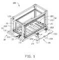
- FIG. 1is an isometric view of an embodiment of a positioning mechanism.
- FIG. 2is an exploded, isometric view of the positioning mechanism shown in FIG. 1 .
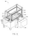
- FIG. 3is an isometric view of a working state of the positioning mechanism shown in FIG. 1 .
- an embodiment of a positioning mechanism 100for positioning a plurality of materials therein, includes a loading assembly 10 and a positioning assembly 20 configured and engaged with the loading assembly 10 .
- the loading assembly 10is capable of bearing the weight of the materials.
- the positioning assembly 20is capable of positioning the materials on the loading assembly 10 .
- the loading assembly 10includes a fixing member 11 , a loading member 12 , a group of hanging members 13 , and a pair of elastic members 15 .
- the loading member 12is provided to contain the materials therein.
- the loading member 12is hung in the fixing member 11 via the hanging members 13 .
- the elastic members 15interconnect the fixing member 11 and the loading member 12 at the opposite side of the loading member 12 , respectively, for limiting the shaking amplitude of the loading member 12 .
- the fixing member 11includes a fixing platform 111 and a fixing frame 113 extending substantially perpendicularly from the fixing platform 111 .
- the fixing platform 111forms a pair of protruding portions 1112 on a surface thereof towards the fixing frame 113 , and the protruding portions 1112 extend substantially perpendicularly outward.
- the protruding portions 1112are a plurality of blocks, and are arranged apart and parallel to each other.
- the fixing platform 111is substantially a rectangular frame, and formed by a plurality of rods connected together. It is can be understood that, the fixing platform 111 can be a planar plate.
- the fixing frame 113is substantially a cuboid frame, and the bottom of the fixing frame 113 is connected to the fixing platform 111 .
- the fixing frame 113forms a group of fixing portions 1131 at the side away from the fixing platform 111 , for fixing an end of the hanging members 13 .
- the number of the fixing portions 1131is equal to the number of the hanging members 13 .
- the number of the fixing portions 1131is four, and the four fixing portions 1131 are respectively positioned on the four corners of the fixing frame 113 .
- the loading member 12includes a supporting plate 121 and a shielding frame 123 extending substantially perpendicularly from the supporting plate 121 .
- the supporting plate 121is substantially a rectangular plate, and the size thereof is smaller than the size of the fixing platform 111 .
- the supporting plate 121forms four securing portions 1211 extending from the opposite sides thereof corresponding to the positions of the four fixing portions 1131 , respectively.
- the supporting plate 121defines a pair of latching portions 1213 corresponding to the protruding portions 1112 .
- the latching portions 1213are a plurality of substantially strip holes, and are latched with the protruding portions 1112 to position the supporting plate 121 .
- the shielding frame 123is substantially a cuboid frame, and the bottom of the shielding frame 123 is connected to the supporting plate 121 .
- the shape of the shielding frame 123is substantially similar to the shape of the fixing frame 113 , and the size of the shielding frame 123 is smaller than the size of the fixing frame 113 .
- the number of the hanging members 13is four.
- the hanging members 13are steel wires.
- Each hanging member 13is fixed with the fixing portion 1131 and the corresponding securing portion 1211 at the opposite distal ends thereof, for hanging the loading member 12 in the fixing frame 113 .
- the length of the hanging members 13is shorter than the height of the fixing frame 113 , and the length of the hanging member 13 in addition to the height of the protruding portion 1112 is greater than the height of the fixing frame 113 , for allowing the protruding portion 1112 to latch with the latching portion 1213 when the loading member 12 is hung by the hanging members 13 .
- the elastic members 15are a plurality of springs, and the number of the elastic members 15 is two.
- Each elastic member 15is bent at the middle thereof to form a V-shape, and the elastic member 15 includes a bending end 151 at the bending position and a pair of connecting ends 153 at the two free ends thereof.
- the bending ends 151are fixed on the opposite sides of the supporting plate 121 at the middle of the sides thereof, and the two pairs of the connecting ends 153 are fixed on the opposite sides of the fixing platform 111 near the bending ends 151 , for balancing the force subjected by the shaking of the loading member 12 .
- the positioning assembly 20includes a pair of first engaging members 21 and a second engaging member 23 engaged with the first engaging members 21 .
- the first engaging members 21are arranged apart on a side next to the securing portions 1211 of the supporting plate 121 .
- the first engaging members 21are substantially sheets, and substantially perpendicularly extending away from the supporting plate 121 .
- Each first engaging member 21defines a connecting portion 213 at an end thereof away from the supporting plate 121 .
- the connecting portion 213 of one of the first engaging member 21is a circular through hole
- the connecting portion 213 of another first engaging member 21is a slotted hole. It can be understood that, the number of the first engaging member 21 can be one or more.
- the connecting portion 213can be of other shapes, such as a rectangular hole.
- the second engaging member 23includes a pair of cylindrical portions 231 , a pair of locking rods 233 mounted in the cylindrical portions 231 , and a mounting plate 235 on which the cylindrical portions 231 are mounted.
- the mounting plate 235is substantially a planar plate, and defines a pair of through holes 2351 near the edge thereof. The distance or diameter of the through holes 2351 is equal to the distance or diameter of the connecting portions 213 . In the illustrated embodiment, the through holes 2351 are circular holes.
- Each cylindrical portion 231defines a receiving hole 2311 along the center axis, and is fixed on the mounting plate 235 with the receiving hole 2311 overlapping the through hole 2351 .
- the locking rods 233are received in the receiving holes 2311 , and capable of extending through the through holes 2351 driven by the cylindrical portion 231 .
- the size of each locking rod 233is corresponding to the size of the connecting portion 213 , and the locking rod 233 includes a latching end 2331 at the distal end thereof towards the through hole 2351 corresponding to the connecting portion 213 .
- the latching end 2331is substantially conic, for easily passing through the through hole 2351 .
- the loading member 12is put into the fixing frame 113 , and the supporting plate 121 faces the fixing platform 111 .
- the protruding portions 1112are latched with the latching portions 1213 .
- an end of each hanging member 13is fixed to the fixing portion 1131 , and the opposite end thereof is fixed to the securing portion 1211 corresponding to the fixing portion 1131 , thus the loading member 12 hangs in the fixing member 11 .
- the bending ends 151 of the elastic members 15are mounted on the opposite sides of the supporting plate 121 , and the pairs of the connecting ends 153 are mounted on the corresponding side of the fixing platform 111 .
- the distances of the bending end 151 to each connecting end 153 of each elastic member 15are the same.
- the first engaging members 21are fixed on the side next to the securing portion 1211 of the supporting plate 121 , and the connecting portions 213 are away from the supporting plate 121 .
- the locking rods 233are mounted in the receiving holes 2311 of the cylindrical portions 231 .
- the cylindrical portions 231are substantially perpendicularly mounted on the mounting plate 235 by engaging with a pair of flanges (not labeled in FIGS. 1 to 3 ).
- the loading assembly 10is placed on a carrier vehicle 200 , and the fixing platform 111 is fixed on the carrier vehicle 200 .
- the fixing frame 113 and the loading member 12are substantially perpendicular to the carrier vehicle 200 .
- a plurality of materials(not shown) are placed on the supporting plate 121 , and transported by the carrier vehicle 200 . Because the loading member 12 is hung in the fixing member 11 , the loading member 12 would shake when the carrier vehicle 200 is moving. Because the protruding portions 1112 are latched with the latching portions 1213 , the shaking amplitude of the loading member 12 is thereby decreased.
- the elastic members 15interconnect the supporting plate 121 with the fixing platform 111 at the symmetrical sides, the speed of shaking of the loading member 12 is slowed down, and the shaking amplitude of the loading member 12 is further decreased. Thus, the materials are steadily transported. Furthermore, the shielding frame 123 can protect the materials from falling off.
- the mounting plate 235is fixed onto a fixing box 300 located beside a predetermined position by fasteners (not shown), and ensuring that the cylindrical portions 231 are perpendicular to the horizontal plane, thus the second engaging member 23 is fixed on the fixing box 300 . At this moment, the locking rods 233 are received in the receiving holes 2311 .
- the predetermined positionis the position of the materials to be processed after transporting. In the illustrated embodiment, the materials are transported to a clamping position to be clamped by a robot arm (not shown). The predetermined position is the clamping position.
- the carrier vehicle 200When the materials are carried to the clamping position, the carrier vehicle 200 is stopped, and the connecting portions 213 are almost aligned with the through holes 2351 . Because the carrier vehicle 200 cannot position the loading member 12 precisely, the materials are located on an adjacent position near the clamping position. Thus, the locking rods 233 received in the receiving holes 2311 are imprecisely aligned with the connecting portions 213 .
- the cylindrical portions 231drive the locking rods 233 to pass through the through holes 2351 to lock with the connecting portions 213 , thus the first engaging members 21 are pushed by the locking rods 233 to make sure the connecting portions 213 are precisely aligned with the through holes 2351 . Because the first engaging members 21 are moved and the shielding frame 123 is hanging in the fixing frame 113 , the loading member 12 is moved after the moving of the first engaging member 21 . Thus the materials placed in the loading member 12 are positioned to the clamping position. After positioning, the robot arm clamps the materials from the loading member 12 . After clamping, the cylindrical portions 231 drive the locking rods 233 to retract to the receiving holes 2311 , so that the locking rods 233 unlock from the connecting portions 213 . Then, the carrier vehicle 200 moves to carry more materials.
- a sliding memberfor example, a sliding wheel or a rolling wheel or a plurality of rolling balls
- the fixing frame 113can be omitted.
- the fixing platform 111can be a planar surface of the carrier vehicle 200 .
- the hanging member 13can be in the form of other high intensity wires, such as suspension rope.
- the elastic members 15can be replaced by other materials, such as rubber bands.
- the latching end 2331can be of other shape of being tapered outwardly along the axis of the locking rod 233 , such as paraboloidal body.
- the elastic members 15are bent at the middle, and the bending ends 151 are fixed on the supporting plate 121 , the pairs of connecting ends 153 are fixed on the supporting platform 111 , thus the elastic members 15 is stressed evenly. Since the protruding portions 1112 are latched with the latching portions 1213 , and the elastic members 15 interconnect the supporting platform 111 with the supporting plate 121 , the supporting plate 121 is steadily transported on the carrier vehicle 200 . Since the supporting plate 121 moves easily relative to the supporting platform 111 , the locking rods 233 extend to latch with the connecting portions 213 , and push the first engaging members 21 and the loading member 12 to move to the clamping position, thus the materials are positioned to the clamping position precisely.
Landscapes
- Engineering & Computer Science (AREA)
- Mechanical Engineering (AREA)
- Transportation (AREA)
- Handcart (AREA)
- Automatic Assembly (AREA)
- Load-Engaging Elements For Cranes (AREA)
Abstract
Description
Claims (14)
Applications Claiming Priority (3)
| Application Number | Priority Date | Filing Date | Title |
|---|---|---|---|
| CN201110273320.0 | 2011-09-15 | ||
| CN201110273320.0ACN102992012B (en) | 2011-09-15 | 2011-09-15 | Positioning mechanism |
| CN201110273320 | 2011-09-15 |
Publications (2)
| Publication Number | Publication Date |
|---|---|
| US20130071200A1 US20130071200A1 (en) | 2013-03-21 |
| US9096387B2true US9096387B2 (en) | 2015-08-04 |
Family
ID=47880805
Family Applications (1)
| Application Number | Title | Priority Date | Filing Date |
|---|---|---|---|
| US13/400,820Expired - Fee RelatedUS9096387B2 (en) | 2011-09-15 | 2012-02-21 | Positioning mechanism |
Country Status (3)
| Country | Link |
|---|---|
| US (1) | US9096387B2 (en) |
| CN (1) | CN102992012B (en) |
| TW (1) | TWI485096B (en) |
Cited By (1)
| Publication number | Priority date | Publication date | Assignee | Title |
|---|---|---|---|---|
| US20190337248A1 (en)* | 2018-05-02 | 2019-11-07 | Murata Machinery, Ltd. | Transport system |
Families Citing this family (28)
| Publication number | Priority date | Publication date | Assignee | Title |
|---|---|---|---|---|
| CN106564020A (en)* | 2016-10-17 | 2017-04-19 | 苏州科维新型包装有限公司 | Machining jig for wood pallet |
| CN108791226B (en)* | 2017-10-16 | 2023-03-10 | 蔚来(安徽)控股有限公司 | Transporter docking device, battery exchange transporter and docking method |
| CN109501746A (en)* | 2017-10-30 | 2019-03-22 | 蔚来汽车有限公司 | Spring suspension chain type floating device |
| CN111727159B (en) | 2018-01-09 | 2022-04-22 | 自动存储科技股份有限公司 | Shifting Mechanisms for Remotely Controlled Vehicles |
| CN109501760B (en)* | 2018-04-10 | 2022-06-03 | 蔚来控股有限公司 | Floating device, battery replacing equipment and battery replacing station |
| NO20181563A1 (en) | 2018-06-12 | 2019-12-13 | Autostore Tech As | Automated storage system and method of retrieving a storage container from storage system |
| JP7357647B2 (en) | 2018-06-12 | 2023-10-06 | アウトストア・テクノロジー・エーエス | How to operate an automatic storage and retrieval system |
| NO344742B1 (en) | 2018-06-12 | 2020-03-30 | Autostore Tech As | A delivery system with an access point and a method of accessing an access point of the delivery system |
| EP3807181B1 (en) | 2018-06-12 | 2023-11-15 | Autostore Technology As | Method for handling malfunctioning vehicles on a rail system and a storage and retrieval system using such a method |
| EP3807175B1 (en) | 2018-06-12 | 2025-07-23 | Autostore Technology As | System for storing and transporting storage containers |
| WO2019238673A1 (en) | 2018-06-12 | 2019-12-19 | Autostore Technology AS | Storage grid with container accessing station with locking device to lock remotely operated vehicle |
| NO344808B1 (en) | 2018-06-12 | 2020-05-04 | Autostore Tech As | Express bin lift for automated storage system |
| NO344750B1 (en) | 2018-06-12 | 2020-04-06 | Autostore Tech As | Unloading arrangement and unloading station, as well as method of unloading an item from a storage container |
| EP4385922A3 (en) | 2018-06-12 | 2024-08-28 | Autostore Technology As | A vehicle tilting device, an access station, a delivery system and a method of accessing a storage container |
| EP3807191A1 (en) | 2018-06-12 | 2021-04-21 | Autostore Technology AS | A method and system for controlling the operation of container handling vehicles and drones serving an automated storage and retrieval system |
| CN112272643B (en) | 2018-06-12 | 2022-08-09 | 自动存储科技股份有限公司 | Container access station with lifting device |
| US11485375B2 (en) | 2018-06-12 | 2022-11-01 | Autostore Technology AS | Unloading arrangement and unloading station, as well as method of unloading an item from a storage container |
| EP3807188A1 (en) | 2018-06-12 | 2021-04-21 | Autostore Technology As | Automated storage system |
| US11993163B2 (en) | 2018-06-12 | 2024-05-28 | Autostore Technology AS | Automated storage system with a container vehicle and a charging system |
| US11352016B2 (en) | 2018-06-12 | 2022-06-07 | Autostore Technology AS | Storage system |
| CN112262088B (en) | 2018-06-12 | 2022-09-20 | 自动存储科技股份有限公司 | Conveyor vehicle, automated storage and retrieval system, and method of transporting storage containers between automated storage and retrieval grids and a second location |
| PL3807189T3 (en) | 2018-06-12 | 2025-05-05 | Autostore Technology AS | Storage system |
| NO345886B1 (en) | 2018-06-12 | 2021-09-27 | Autostore Tech As | Vehicle tilting Device and Method of accessing a Storage container |
| US12246757B2 (en) | 2018-06-12 | 2025-03-11 | Autostore Technology AS | Safety device for a remotely operated vehicle, a system and a method of improving the operational safety of a grid system |
| EP3807182B1 (en) | 2018-06-12 | 2025-07-23 | Autostore Technology As | A delivery system with an access point and a method of accessing an access point of the delivery system |
| CN112218806B (en) | 2018-06-12 | 2022-11-29 | 自动存储科技股份有限公司 | Storage system |
| CN111634632B (en)* | 2020-05-26 | 2024-11-26 | 哈尔滨焊接研究院有限公司 | Island welding production line and production method for the middle trough/hydraulic support structure of coal mining scraper conveyor |
| CN112027559A (en)* | 2020-09-04 | 2020-12-04 | 泉州泉港聚业工业设计有限公司 | Transfer conveyer is used in female production of arranging of cubical switchboard |
Citations (13)
| Publication number | Priority date | Publication date | Assignee | Title |
|---|---|---|---|---|
| US4746258A (en)* | 1985-09-13 | 1988-05-24 | Litton Systems, Inc. | Floating table for article transport vehicle |
| US4818171A (en)* | 1987-10-22 | 1989-04-04 | Caterpillar Industrial Inc. | Pallet transferring arrangement and method |
| US4861220A (en)* | 1988-05-27 | 1989-08-29 | Caterpillar Industrial Inc. | Load positioning assembly and method |
| US4893963A (en)* | 1987-09-11 | 1990-01-16 | Aerospatiale Societe Nationale Industrielle | System for coupling two bodies, for example a carriage and a machining station |
| US4915569A (en)* | 1987-02-05 | 1990-04-10 | Oerlikon Motch Corporation | Combination machine tool apparatus and pallet changing system |
| US4940378A (en)* | 1988-09-29 | 1990-07-10 | Jd-Technologie Ag | Positioning device for positioning a load carrying platform relative to a docking station |
| US5306109A (en)* | 1991-04-23 | 1994-04-26 | Kreuzer Gmbh & Co. Ohg | Transportable medical apparatus, in particular infusion supply |
| US5354153A (en)* | 1991-11-08 | 1994-10-11 | Pluritec Italia S.P.A. | Machine tool part loading and unloading method and device particularly for machining printed circuit boards |
| US5451133A (en)* | 1993-03-31 | 1995-09-19 | Eastman Kodak Company | Docking apparatus |
| US5641260A (en)* | 1995-04-13 | 1997-06-24 | Gray; Stephen Jay | Shaft coupling device and locking mechanism |
| US6231292B1 (en)* | 1997-03-26 | 2001-05-15 | De La Rue Giori S.A. | Method for unloading reams of sheets and apparatus for unloading reams of sheets |
| US6394743B1 (en)* | 1999-12-20 | 2002-05-28 | Cymer, Inc. | Cart for module replacement |
| US6454512B1 (en)* | 1999-03-18 | 2002-09-24 | Pri Automation, Inc. | Person-guided vehicle |
Family Cites Families (7)
| Publication number | Priority date | Publication date | Assignee | Title |
|---|---|---|---|---|
| SE459169B (en)* | 1988-02-04 | 1989-06-12 | Crister Stark | Lifting equipment for container or cargo platform |
| CN101205010B (en)* | 2007-12-19 | 2010-07-07 | 友达光电股份有限公司 | Positioning device |
| WO2009149544A1 (en)* | 2008-06-11 | 2009-12-17 | Jeffrey Douglas Gaudette | Title: apparatus, systems and methods for securing parts |
| CN201417897Y (en)* | 2009-06-01 | 2010-03-03 | 江苏金华厦电气有限公司 | Carrier loader of middle-arranged switch cabinet |
| JP5168594B2 (en)* | 2009-11-25 | 2013-03-21 | 株式会社ダイフク | Board transfer equipment |
| CN101962263B (en)* | 2010-06-08 | 2012-07-11 | 东旭集团有限公司 | Device and method for adjusting and positioning a flat glass A-frame |
| CN201777631U (en)* | 2010-08-23 | 2011-03-30 | 宝山钢铁股份有限公司 | Automatically-adjustable scatter-preventing devices for guide chute of belt conveyor |
- 2011
- 2011-09-15CNCN201110273320.0Apatent/CN102992012B/ennot_activeExpired - Fee Related
- 2011-09-19TWTW100133565Apatent/TWI485096B/ennot_activeIP Right Cessation
- 2012
- 2012-02-21USUS13/400,820patent/US9096387B2/ennot_activeExpired - Fee Related
Patent Citations (13)
| Publication number | Priority date | Publication date | Assignee | Title |
|---|---|---|---|---|
| US4746258A (en)* | 1985-09-13 | 1988-05-24 | Litton Systems, Inc. | Floating table for article transport vehicle |
| US4915569A (en)* | 1987-02-05 | 1990-04-10 | Oerlikon Motch Corporation | Combination machine tool apparatus and pallet changing system |
| US4893963A (en)* | 1987-09-11 | 1990-01-16 | Aerospatiale Societe Nationale Industrielle | System for coupling two bodies, for example a carriage and a machining station |
| US4818171A (en)* | 1987-10-22 | 1989-04-04 | Caterpillar Industrial Inc. | Pallet transferring arrangement and method |
| US4861220A (en)* | 1988-05-27 | 1989-08-29 | Caterpillar Industrial Inc. | Load positioning assembly and method |
| US4940378A (en)* | 1988-09-29 | 1990-07-10 | Jd-Technologie Ag | Positioning device for positioning a load carrying platform relative to a docking station |
| US5306109A (en)* | 1991-04-23 | 1994-04-26 | Kreuzer Gmbh & Co. Ohg | Transportable medical apparatus, in particular infusion supply |
| US5354153A (en)* | 1991-11-08 | 1994-10-11 | Pluritec Italia S.P.A. | Machine tool part loading and unloading method and device particularly for machining printed circuit boards |
| US5451133A (en)* | 1993-03-31 | 1995-09-19 | Eastman Kodak Company | Docking apparatus |
| US5641260A (en)* | 1995-04-13 | 1997-06-24 | Gray; Stephen Jay | Shaft coupling device and locking mechanism |
| US6231292B1 (en)* | 1997-03-26 | 2001-05-15 | De La Rue Giori S.A. | Method for unloading reams of sheets and apparatus for unloading reams of sheets |
| US6454512B1 (en)* | 1999-03-18 | 2002-09-24 | Pri Automation, Inc. | Person-guided vehicle |
| US6394743B1 (en)* | 1999-12-20 | 2002-05-28 | Cymer, Inc. | Cart for module replacement |
Cited By (2)
| Publication number | Priority date | Publication date | Assignee | Title |
|---|---|---|---|---|
| US20190337248A1 (en)* | 2018-05-02 | 2019-11-07 | Murata Machinery, Ltd. | Transport system |
| US10875268B2 (en)* | 2018-05-02 | 2020-12-29 | Murata Machinery, Ltd. | Transport system |
Also Published As
| Publication number | Publication date |
|---|---|
| TWI485096B (en) | 2015-05-21 |
| TW201311533A (en) | 2013-03-16 |
| CN102992012B (en) | 2015-07-15 |
| US20130071200A1 (en) | 2013-03-21 |
| CN102992012A (en) | 2013-03-27 |
Similar Documents
| Publication | Publication Date | Title |
|---|---|---|
| US9096387B2 (en) | Positioning mechanism | |
| US9233474B2 (en) | Clamping apparatus | |
| US9333601B2 (en) | Storage mechanism and feeding device using the same | |
| JP6360259B2 (en) | Battery device, battery unit and battery device installation method | |
| US20160280470A1 (en) | Transfer device | |
| US20140178168A1 (en) | Transporting device | |
| TW200824996A (en) | Stacker crane | |
| CN105730969B (en) | A kind of transport device | |
| US20110068548A1 (en) | Transport pallet | |
| US9227824B2 (en) | Adjustable forklift load backrest | |
| US20130136568A1 (en) | Handling mechanism | |
| CN114852153A (en) | Circuit board removes transportation protection device | |
| KR20170000772U (en) | Trolley | |
| KR20180119970A (en) | Unit for supporting cassette and vehicle having the unit | |
| CN217804838U (en) | Work piece placing trolley | |
| CN211590149U (en) | Robot and conveyance device | |
| CN205328167U (en) | Commodity circulation positioning device | |
| CN104444761B (en) | Transport hanging tool | |
| CN208856398U (en) | Material conveying mechanism | |
| CN207861806U (en) | Handling device | |
| CN222114185U (en) | A magnetic suspension fixture loading system | |
| CN219237714U (en) | Tool for transferring battery parts | |
| CN216835699U (en) | Double-screw bolt carrying mechanism | |
| CN220765130U (en) | Turnover box with locking function | |
| CN216229388U (en) | Rectangular coordinate robot frame section bar structure |
Legal Events
| Date | Code | Title | Description |
|---|---|---|---|
| AS | Assignment | Owner name:HON HAI PRECISION INDUSTRY CO., LTD., TAIWAN Free format text:ASSIGNMENT OF ASSIGNORS INTEREST;ASSIGNORS:LIU, DONG-CHENG;CHEN, KUN;XIAO, YA-JUAN;REEL/FRAME:027734/0088 Effective date:20120218 Owner name:HONG FU JIN PRECISION INDUSTRY (SHENZHEN) CO., LTD Free format text:ASSIGNMENT OF ASSIGNORS INTEREST;ASSIGNORS:LIU, DONG-CHENG;CHEN, KUN;XIAO, YA-JUAN;REEL/FRAME:027734/0088 Effective date:20120218 | |
| STCF | Information on status: patent grant | Free format text:PATENTED CASE | |
| AS | Assignment | Owner name:FUSHIRUI PRECISION INDUSTRY (JINCHENG) CO., LTD. Free format text:ASSIGNMENT OF ASSIGNORS INTEREST;ASSIGNORS:HONG FU JIN PRECISION INDUSTRY (SHENZHEN) CO., LTD.;HON HAI PRECISION INDUSTRY CO., LTD.;REEL/FRAME:039249/0600 Effective date:20160513 | |
| FEPP | Fee payment procedure | Free format text:MAINTENANCE FEE REMINDER MAILED (ORIGINAL EVENT CODE: REM.); ENTITY STATUS OF PATENT OWNER: LARGE ENTITY | |
| LAPS | Lapse for failure to pay maintenance fees | Free format text:PATENT EXPIRED FOR FAILURE TO PAY MAINTENANCE FEES (ORIGINAL EVENT CODE: EXP.); ENTITY STATUS OF PATENT OWNER: LARGE ENTITY | |
| STCH | Information on status: patent discontinuation | Free format text:PATENT EXPIRED DUE TO NONPAYMENT OF MAINTENANCE FEES UNDER 37 CFR 1.362 | |
| FP | Lapsed due to failure to pay maintenance fee | Effective date:20190804 |