US9095633B1 - Object decontamination apparatus with an adjustable ultraviolet source - Google Patents
Object decontamination apparatus with an adjustable ultraviolet sourceDownload PDFInfo
- Publication number
- US9095633B1 US9095633B1US14/530,510US201414530510AUS9095633B1US 9095633 B1US9095633 B1US 9095633B1US 201414530510 AUS201414530510 AUS 201414530510AUS 9095633 B1US9095633 B1US 9095633B1
- Authority
- US
- United States
- Prior art keywords
- source
- decontamination apparatus
- target object
- decontamination
- arm
- Prior art date
- Legal status (The legal status is an assumption and is not a legal conclusion. Google has not performed a legal analysis and makes no representation as to the accuracy of the status listed.)
- Active
Links
- 238000005202decontaminationMethods0.000titleclaimsabstractdescription161
- 230000003588decontaminative effectEffects0.000titleclaimsabstractdescription104
- 244000052769pathogenSpecies0.000claimsabstractdescription29
- 230000001717pathogenic effectEffects0.000claimsabstractdescription29
- 230000007246mechanismEffects0.000claimsabstractdescription6
- 230000033001locomotionEffects0.000claimsdescription16
- 230000009467reductionEffects0.000claimsdescription8
- 230000004044responseEffects0.000claimsdescription5
- 230000004913activationEffects0.000claimsdescription2
- 238000004891communicationMethods0.000description12
- 239000000645desinfectantSubstances0.000description8
- 238000000034methodMethods0.000description7
- 230000003068static effectEffects0.000description7
- 208000015181infectious diseaseDiseases0.000description6
- 230000008859changeEffects0.000description5
- 239000000356contaminantSubstances0.000description5
- 239000000523sampleSubstances0.000description5
- 230000001960triggered effectEffects0.000description5
- 229920002799BoPETPolymers0.000description4
- CURLTUGMZLYLDI-UHFFFAOYSA-NCarbon dioxideChemical compoundO=C=OCURLTUGMZLYLDI-UHFFFAOYSA-N0.000description4
- 238000005516engineering processMethods0.000description4
- 230000002028prematureEffects0.000description4
- 230000002458infectious effectEffects0.000description3
- 239000000463materialSubstances0.000description3
- 238000012544monitoring processMethods0.000description3
- 238000000926separation methodMethods0.000description3
- 239000005041Mylar™Substances0.000description2
- 230000009471actionEffects0.000description2
- 230000003213activating effectEffects0.000description2
- 229910002092carbon dioxideInorganic materials0.000description2
- 239000001569carbon dioxideSubstances0.000description2
- 230000008878couplingEffects0.000description2
- 238000010168coupling processMethods0.000description2
- 238000005859coupling reactionMethods0.000description2
- 230000005672electromagnetic fieldEffects0.000description2
- 238000005286illuminationMethods0.000description2
- 238000009434installationMethods0.000description2
- 239000007788liquidSubstances0.000description2
- 230000004048modificationEffects0.000description2
- 238000012986modificationMethods0.000description2
- 230000003287optical effectEffects0.000description2
- 238000003825pressingMethods0.000description2
- 230000007480spreadingEffects0.000description2
- 230000004308accommodationEffects0.000description1
- 230000004075alterationEffects0.000description1
- 238000010009beatingMethods0.000description1
- 238000005452bendingMethods0.000description1
- 230000008901benefitEffects0.000description1
- 230000005540biological transmissionEffects0.000description1
- 238000006243chemical reactionMethods0.000description1
- 238000004140cleaningMethods0.000description1
- 238000001816coolingMethods0.000description1
- 239000006071creamSubstances0.000description1
- 230000005670electromagnetic radiationEffects0.000description1
- 230000006870functionEffects0.000description1
- 230000005484gravityEffects0.000description1
- 230000000977initiatory effectEffects0.000description1
- 239000004973liquid crystal related substanceSubstances0.000description1
- 238000012806monitoring deviceMethods0.000description1
- 239000004033plasticSubstances0.000description1
- 229920003023plasticPolymers0.000description1
- 229920006267polyester filmPolymers0.000description1
- 230000008569processEffects0.000description1
- 230000001737promoting effectEffects0.000description1
- 230000001681protective effectEffects0.000description1
- 238000002310reflectometryMethods0.000description1
- 238000009877renderingMethods0.000description1
- 230000000284resting effectEffects0.000description1
- 239000007787solidSubstances0.000description1
- 238000001228spectrumMethods0.000description1
Images


Classifications
- A—HUMAN NECESSITIES
- A61—MEDICAL OR VETERINARY SCIENCE; HYGIENE
- A61L—METHODS OR APPARATUS FOR STERILISING MATERIALS OR OBJECTS IN GENERAL; DISINFECTION, STERILISATION OR DEODORISATION OF AIR; CHEMICAL ASPECTS OF BANDAGES, DRESSINGS, ABSORBENT PADS OR SURGICAL ARTICLES; MATERIALS FOR BANDAGES, DRESSINGS, ABSORBENT PADS OR SURGICAL ARTICLES
- A61L2/00—Methods or apparatus for disinfecting or sterilising materials or objects other than foodstuffs or contact lenses; Accessories therefor
- A61L2/02—Methods or apparatus for disinfecting or sterilising materials or objects other than foodstuffs or contact lenses; Accessories therefor using physical phenomena
- A61L2/08—Radiation
- A61L2/10—Ultraviolet radiation
- A—HUMAN NECESSITIES
- A61—MEDICAL OR VETERINARY SCIENCE; HYGIENE
- A61L—METHODS OR APPARATUS FOR STERILISING MATERIALS OR OBJECTS IN GENERAL; DISINFECTION, STERILISATION OR DEODORISATION OF AIR; CHEMICAL ASPECTS OF BANDAGES, DRESSINGS, ABSORBENT PADS OR SURGICAL ARTICLES; MATERIALS FOR BANDAGES, DRESSINGS, ABSORBENT PADS OR SURGICAL ARTICLES
- A61L2/00—Methods or apparatus for disinfecting or sterilising materials or objects other than foodstuffs or contact lenses; Accessories therefor
- A61L2/24—Apparatus using programmed or automatic operation
- A—HUMAN NECESSITIES
- A61—MEDICAL OR VETERINARY SCIENCE; HYGIENE
- A61L—METHODS OR APPARATUS FOR STERILISING MATERIALS OR OBJECTS IN GENERAL; DISINFECTION, STERILISATION OR DEODORISATION OF AIR; CHEMICAL ASPECTS OF BANDAGES, DRESSINGS, ABSORBENT PADS OR SURGICAL ARTICLES; MATERIALS FOR BANDAGES, DRESSINGS, ABSORBENT PADS OR SURGICAL ARTICLES
- A61L2202/00—Aspects relating to methods or apparatus for disinfecting or sterilising materials or objects
- A61L2202/10—Apparatus features
- A61L2202/14—Means for controlling sterilisation processes, data processing, presentation and storage means, e.g. sensors, controllers, programs
- A—HUMAN NECESSITIES
- A61—MEDICAL OR VETERINARY SCIENCE; HYGIENE
- A61L—METHODS OR APPARATUS FOR STERILISING MATERIALS OR OBJECTS IN GENERAL; DISINFECTION, STERILISATION OR DEODORISATION OF AIR; CHEMICAL ASPECTS OF BANDAGES, DRESSINGS, ABSORBENT PADS OR SURGICAL ARTICLES; MATERIALS FOR BANDAGES, DRESSINGS, ABSORBENT PADS OR SURGICAL ARTICLES
- A61L2202/00—Aspects relating to methods or apparatus for disinfecting or sterilising materials or objects
- A61L2202/10—Apparatus features
- A61L2202/16—Mobile applications, e.g. portable devices, trailers, devices mounted on vehicles
- A—HUMAN NECESSITIES
- A61—MEDICAL OR VETERINARY SCIENCE; HYGIENE
- A61L—METHODS OR APPARATUS FOR STERILISING MATERIALS OR OBJECTS IN GENERAL; DISINFECTION, STERILISATION OR DEODORISATION OF AIR; CHEMICAL ASPECTS OF BANDAGES, DRESSINGS, ABSORBENT PADS OR SURGICAL ARTICLES; MATERIALS FOR BANDAGES, DRESSINGS, ABSORBENT PADS OR SURGICAL ARTICLES
- A61L2202/00—Aspects relating to methods or apparatus for disinfecting or sterilising materials or objects
- A61L2202/20—Targets to be treated
- A61L2202/25—Rooms in buildings, passenger compartments
Definitions
- This applicationrelates generally to a decontamination method and apparatus and, more specifically, to an apparatus and method for emitting ultraviolet light onto surfaces of a room for decontamination purposes.
- contaminantsbiologically-active contaminants
- contaminantscan remain viable on the contaminated surfaces to reproduce and infect others such as subsequent patients and/or visitors, for example, who enter the room and make contact with those surfaces.
- healthcare facilitiesmust conduct decontamination procedures in the rooms as frequently as possible.
- a room where such contaminants are prevalentis an inpatient hospital room.
- Surfacessuch as tray tables, bed rails, and television remote controls frequently come into direct contact with patients during their stay in the room. These surfaces should be decontaminated frequently to avoid a buildup of contaminants and minimize the risk of spreading an infection from the patient to another person who may come into contact with the surfaces.
- manually decontaminating such roomsis labor intensive, requiring personnel to adhere to strict guidelines governing the use of liquid disinfectants. Further, depending on the surfaces being decontaminated, it may not be practical to provide the entirety of the surfaces with liquid disinfectants in compliance with those guidelines.
- the subject applicationinvolves a decontamination apparatus including a base, and a source that emits UVC light at a suitable intensity to at least partially decontaminate a target object and render the target object pathogen reduced.
- An adjustable supportis coupled to the base and supports the source, the adjustable support including an adjustment mechanism that is manipulable to adjust a position of the source relative to the base.
- a range sensorsenses a property indicative of a distance separating the source of UVC light from the target object to be rendered pathogen reduced.
- a controlleris operatively connected to the source to control emission of the UVC light.
- the controlleris in communication with the range sensor to receive a signal indicative of the distance separating the source from the target object as sensed by the range sensor and includes a variable component that establishes at least one of a duration of a decontamination process and the suitable intensity of UVC light as a function of the distance separating the source from the target object.
- the subject applicationinvolves a decontamination apparatus that includes a base, and a source that emits UVC light at a suitable intensity to at least partially decontaminate a target object and thereby render the target object pathogen reduced.
- the sourceincludes a UVC bulb that is operable to emit the UVC light, and a reflective shield arranged adjacent to the UVC bulb to reflect at least a portion of the UVC light emitted by the UVC bulb generally away from the target object in a focused direction, generally toward the target object.
- the reflective shieldincludes a plurality of arcuate regions, each extending about a different axis with a different orientation.
- An adjustable supportis coupled to the base and supports the source.
- the adjustable supportincludes an adjustment mechanism that can be manipulated to adjust a position of the source relative to the base.
- a controlleris operatively connected to the source to control emission of the UVC light by the source.
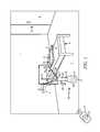
- FIG. 1shows a schematic representation of a decontamination system installed in an inpatient hospital room
- FIG. 2is a bottom view of a source of a disinfecting agent in the form of UVC light, the source being provided adjacent to a terminal end of an articulated arm and being viewed from the perspective indicated by line 2 - 2 in FIG. 1 ;
- FIG. 3is a partially-cutaway side view of the source taken along line 3 - 3 in FIG. 2 ;
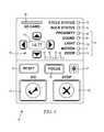
- FIG. 4is a front view schematically depicting a controller of a decontamination system
- FIG. 5shows a side view of an alternate embodiment of a decontamination apparatus including a base in a stowed configuration for transportation of the decontamination apparatus;
- FIG. 6shows a side view of an alternate embodiment of a decontamination apparatus including a base in a stowed configuration for transportation of the decontamination apparatus;
- FIG. 7shows the alternate embodiment of the decontamination apparatus appearing in FIG. 5 with the base in a deployed configuration in which the decontamination apparatus is to be used to decontaminate a surface
- FIG. 8shows the alternate embodiment of the decontamination apparatus appearing in FIG. 6 with the base in a deployed configuration in which the decontamination apparatus is to be used to decontaminate a surface
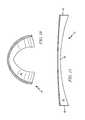
- FIG. 9shows a perspective view of a reflective shield for directing UVC light toward a target surface
- FIG. 10is a sectional view of the reflective shield shown in FIG. 9 taken along line 10 - 10 ;
- FIG. 11is a sectional view of the reflective shield shown in FIG. 9 taken along line 11 - 11 .
- the phrase “at least one of”, if used herein, followed by a plurality of members hereinmeans one of the members, or a combination of more than one of the members.
- the phrase “at least one of a first widget and a second widget”means in the present application: the first widget, the second widget, or the first widget and the second widget.
- “at least one of a first widget, a second widget and a third widget”means in the present application: the first widget, the second widget, the third widget, the first widget and the second widget, the first widget and the third widget, the second widget and the third widget, or the first widget and the second widget and the third widget.
- FIG. 1shows an illustrative embodiment of an inpatient room 1 in a hospital that is accessible through a door 6 separating the inpatient room from a hallway, for example.
- the room 1is provided with a patient bed 4 and a tray table 5 that can extend over the patient lying in the bed 4 .
- the room 1can also include other fixtures and features commonly found in inpatient rooms such as a television, health-monitoring equipment such as a heart-rate monitor, telephone, nightstand, etc. . . . .
- the present disclosurefocuses on the decontamination of items within an inpatient hospital room 1 for the sake of clarity and brevity, the technology disclosed herein can be used to decontaminate objects located anywhere, such as in hotel rooms any other public accommodations.
- a decontamination apparatus 10operable to at least partially decontaminate, or at least render pathogen reduced, contaminated surfaces such as the tray table 5 within that room 1 .
- the decontamination processcan be initiated manually, and performed by the decontamination apparatus 10 on demand, and/or can optionally be initiated automatically according to a predetermined schedule when the room 1 is unoccupied, as determined utilizing a plurality of sensors as described below.
- Rendering the surfaces “pathogen reduced” with the decontamination apparatus 10does not necessarily require the subject surfaces to be 100% sterile, free of any and all living organisms that can viably reproduce. Instead, to be considered pathogen reduced, there must be a lower level of living contagions on the decontaminated surfaces capable of reproducing or otherwise causing an infection after performance of the decontamination process than the level that existed on the surfaces prior to performance of the decontamination process.
- the exposed surfaces in the bathroomcan be considered to be pathogen reduced if at least a 1 log 10 reduction of such contagions on the surfaces remain infectious (i.e., no more than 1/10th of the biologically-active contagions originally on the exposed surfaces remain active or infectious at a time when the decontamination process is completed) occurs.
- the surfacescan be considered pathogen reduced once at least a 3 log 10 reduction (i.e., 1/1,000th) of such contagions on the surfaces is achieved.
- the decontamination apparatus 10includes one or a plurality of sources 12 that direct a disinfecting agent toward the surface(s) to be rendered pathogen reduced, a redundant occupant sensing system that determines whether the room 1 is occupied or not, and a controller 16 that interferes with emission of the disinfecting agent by the source(s) 12 if the room 1 is, or becomes occupied based on a signal from the occupant sensing system.
- Each source 12can be any apparatus that emits a disinfecting agent that, when exposed to the surfaces to render those exposed surfaces pathogen reduced.
- each source 12is an ultraviolet source that is to be energized to emit UVC light as the disinfecting agent, and the surface to be rendered pathogen reduced is the tray table 5 .
- each source 12includes at least one, and optionally a plurality of UVC bulbs 14 ( FIG. 2 ) coupled to a reflective shield 18 coupled to an underside of a housing 20 .
- the housing 20can be pivotally coupled to a distal end of an articulated arm 22 or other suitable support that allows the housing 20 , and accordingly the bulbs 14 , to be pivoted about a rotational axis in the directions indicated by arrow 21 and otherwise positioned in a suitable position relative to the tray table 5 to achieve the desired level of decontamination within a predetermined period of time, once activated.
- each arm 22has a portion including an adjustable length extending generally away from a base portion 25 , which can be facilitated by an external member 24 that telescopically receives an internal member 26 , or other suitable length adjustment mechanism (e.g, sliding track, etc. . . . ).
- a locking member 27such as a spring-biased pin urged toward a locking position, etc. . . . can be provided to one or both of the external and internal members 24 , 26 to maintain a desired length of the arm 22 , once manually established.
- a hinge 28 or other connector suitable to allow angular adjustment of the arm 22 relative to the base 25can be disposed between the base 25 and the arm 22 .
- a bendable joint 30can also be provided anywhere along the length of the arm 22 , such as adjacent to the distal end of the arm 22 where the housing 20 is supported.
- the joint 30can be formed from a plastically-deformable flexible material that can be manually bent to position the housing 20 , yet be sufficiently rigid to maintain the position of the housing relative to the arm 22 once the bending force has been removed.
- a hinge 32can also optionally be positioned along the arm 22 before and/or after the joint 30 to allow further adjustment of the position of the housing 20 and bulbs to achieve the desired coverage of the tray table 5 with UVC light.
- the hinge(s) 32can be selectively lockable, meaning a locking member such as a set screw, for example, can be loosened to allow the structures coupled to opposite sides of the hinge(s) 32 to be pivotally adjusted relative to each other. Once the desired adjustment has been completed, the set screw or other locking member can be tightened to interfere with further pivotal adjustment of the structures relative to each other.
- a locking membersuch as a set screw
- the base 25supports the arms 22 at a desired elevation above the floor 7 of the room 1 .
- the base 25supports the controller 16 that can be manipulated by a user to control operation of the decontamination apparatus 10 (e.g., independently control operation of each source 12 to emit UVC light, optionally to cause one source 12 to remain energized longer than another one of the sources 12 ), and optionally houses an on-board power supply such as a rechargeable battery bank 37 storing electric energy that can be used to energize the bulbs 14 and power the controller 16 .
- the battery bank 37can be housed within a recess defined by a lower cap 39 of the base 25 comprising an arcuate bottom surface 41 that rests on the floor 7 .
- the arcuate bottom surface 41allows the decontamination apparatus to wobble, if necessary, to properly position the bulbs 14 for a decontamination process.
- the base 25or another portion for the decontamination apparatus can optionally be provided with an accelerometer, tip sensor, gyroscope or other type of monitoring device that can sense when the decontamination apparatus 10 has been picked up, falls over, moved or otherwise disturbed. In such events, an active decontamination process can be terminated and a new decontamination process can be prevented from being initiated.
- the lower cap 39can be threadedly connected to the base 25 so as to be removable, and optionally interchangeable. For removable embodiments, the lower cap 39 can be unscrewed from the base 25 to grant access to the battery bank 37 .
- a depleted battery bank 37can then be removed from the decontamination apparatus 10 and replaced with a charged battery bank 37 .
- the lower cap with the depleted battery bank 37can be replaced in its entirety with another lower cap 39 with a charged battery bank 37 .
- the decontamination apparatuscan include a power cord that is to be plugged into an AC mains electric outlet supplied by an electric power utility to obtain the electric energy needed to power the decontamination apparatus 10 .
- the base 25can also optionally be provided with a connector, shown in FIG. 1 as a hook 35 that is generally shaped to resemble an upside-down “L”.
- the hook 35can be placed over a receiver or other portion of a cart hauling cleaning supplies, for example, or any other transport vehicle, to allow transportation of the decontamination apparatus 10 throughout the hospital for use in a plurality of different rooms 1 .
- the embodiments of the base 25are described above as a static structure that supports the arms 22 at a desired elevation above the floor 7 of the room 1 and optionally housing a battery bank 37 .
- alternate embodiments of the base 25 ′are schematically shown in FIGS. 5-8 .
- the base 25 ′includes a plurality (e.g., three in the illustrated embodiment) of arcuate panels 82 , each pivotally coupled by a hinge 84 or other adjustable fastener to static portion 86 of the base 25 ′ to which the arms 22 are coupled.
- Each panel 82has an arcuate shape across a lateral dimension, to form approximately one third (1 ⁇ 3) of the total circumference of the substantially-tubular base 25 ′ when adjusted to the stowed configuration.
- each panel 82In the stowed configuration, each panel 82 extends substantially vertically upward from the static portion 86 of the base 25 ′ to define an internal chamber 88 into which the arms 22 , and optionally the bulbs 14 , are at least partially recessed while the decontamination apparatus 10 is in the stowed configuration.
- Inward-facing surfaces of each panel 82can optionally be coated with, or otherwise formed from a light-colored material (e.g., white, off white, cream, light gray, etc. . . . ) and/or a reflective material (e.g., metallic, reflective plastic, etc. . . . ) to enhance the reflectivity of UVC light emitted by the bulbs 14 while at least partially recessed in the chamber 88 .
- a light-colored materiale.g., white, off white, cream, light gray, etc. . . .
- a reflective materiale.g., metallic, reflective plastic, etc. . . .
- the bulbs 14can be activated to emit UVC light.
- This UVC lightwill be reflected by the inward-facing surfaces of the panels 82 , thereby promoting complete exposure of the entire internal periphery of the chamber 88 .
- Such activation of the bulbs 14can decontaminate the inward-facing surfaces of the panels 82 , thereby mitigate the risk of spreading the pathogen from one environment to another as the decontamination apparatus 10 is transported there between.
- the base 25 ′can be converted from the stowed configuration to a deployed configuration, shown in FIGS. 7 and 8 , in which the decontamination apparatus 10 is ready for use.
- a conversioncan be achieved by pivotally adjusting the panels 82 about their respective hinges 84 , such that the panels 82 extend downward from the static portion 86 at an angle (e.g., between about 45° and 90° from horizontal).
- the inward-facing surfaces of the panels 82are adjusted to become substantially outward-facing surfaces in the deployed configuration, thereby exposing those surfaces to the elements within the room in which the decontamination apparatus 10 is located.
- the panels 82act as legs that separate the static portion 86 from an underlying ground surface, and elevate the static portion 86 and arms 22 to a height above the underlying ground surface suitable for performing the desired decontamination process.
- the reflective shield 18 in FIG. 2includes an arcuate or paneled region 34 that is configured to reflect UVC light emitted upwardly from the bulbs 14 in a downward direction, generally towards the tray table 5 where the UVC light can decontaminate the exposed surfaces thereof.
- the arcuate or paneled region 34can include a continuous curvature in multiple planes or a plurality planar and reflective structures arranged to form a somewhat curved profile to achieve the desired light pattern for the tray table 5 or other object being decontaminated. For example, and as schematically illustrated in FIGS.
- the reflective shield 18can include a reflective surface 94 that faces the bulbs 14 that has a gradually varying, or at least a variable, radius of curvature in a transverse direction relative to a longitudinal axis 47 along the length of that longitudinal axis 47 ( FIG. 2 ).
- the radius of curvature of the reflective surface of the reflective shield 18can be greatest at a central region 96 ( FIG. 11 ) adjacent to the location of a focal indicator 40 , described below.
- the radius of curvature in the transverse directionis less than the radius of curvature at this central region at locations further toward opposite, longitudinal ends 46 of the reflective shield 18 along the longitudinal axis 47 .
- the radius of curvaturecan optionally be the smallest at those longitudinal ends 46 .
- the radius of curvatureis used to describe the shape of the reflective surface of the reflective shield 18 , it is to be understood that the cross-sectional shape of the reflective surface does not necessarily have a constant radius of curvature.
- the cross sectional shape of the reflective surface 94 taken along line 10 - 10 in FIG. 9a cross section that is depicted in FIG. 10 , can be a downward-opening parabolic shape, or other desired arcuate shape that more-narrowly focuses UVC light emitted by the bulbs 14 in the transverse direction adjacent to the longitudinal ends 46 than adjacent to the central region along the longitudinal axis 47 .
- a focal indicator 40can optionally be provided to the reflective shield 18 and/or housing 20 . Locating the focal indicator 40 between the UVC bulbs 14 as shown in FIG. 2 allows the focal indicator to identify a general direction that is representative of the direction in which the UVC light from the UVC bulbs 14 will be focused.
- the focal indicator 40can include a light emitting diode (“LED”), laser light, or other optical indicator that can project light that will illuminate a region of a surface on which the UVC light from the UVC bulbs 14 is centered. An example of such a region is illustrated in FIG. 1 by the broken lines 45 appearing on the tray table 5 .
- a usercan essentially aim the UVC light toward the surfaces to be rendered pathogen reduced, and get a sense of the portion of the tray table 5 that will be suitably exposed to the UVC light during a decontamination apparatus to be considered pathogen reduced within a predetermined period of time for the power of the bulbs 14 employed.
- FIG. 8shows an alternate embodiment of the reflective shield 18 ′.
- the present embodimentincludes a collapsible shield 18 ′ that is configured to reflect UVC light emitted by a plurality (e.g., two illustrated in FIG. 8 ) of bulbs 14 .
- the reflective collapsible shield 18 ′includes an aluminized or otherwise metalized Mylar (e.g., stretched polyester film, also commonly referred to as biaxially-oriented polyethylene terephthalate or “BoPET”, for short) sheet 90 spanning a distance between poles 92 extending in different, optionally diverging or opposite directions from the static portion 86 of the base 25 ′.
- Mylare.g., stretched polyester film, also commonly referred to as biaxially-oriented polyethylene terephthalate or “BoPET”, for short
- Mylaris one example of a suitable reflective surface that is collapsible, but the present disclosure is not so limited, as any reflective surface that can be collapsed to fit within the chamber 88 of the base 25 ′ in the stowed configuration will suffice.
- One or each of the poles 92can optionally be spring biased, urged by gravity or otherwise urged toward their diverging orientations in which the sheet 90 is pulled substantially taut to form a reflective surface extending between the poles 92 .
- the poles 92are adjusted toward each other, allowing the sheet 90 to be folded in a fan-like manner to fit within the chamber 88 formed by the panels 82 of the base 25 ′, as shown in FIG. 6 .
- the embodiment of the source 12 shown in FIG. 2includes a plurality of elongated UVC bulbs 14 that emit UVC light as the disinfecting agent. Since such a source 12 emits only UVC light, it is dedicated for performing the decontamination process described herein. But regardless of the configuration of the UVC bulbs 14 , the source 12 can optionally include an intensity sensor 48 that senses an intensity of the UVC light emitted by each UVC bulb 14 present. For the sake of brevity, the present technology will be described hereinafter with reference to the elongated UVC bulbs 14 , although any other desired configuration of UVC bulb is a viable alternative. The intensity of the UVC light emitted by the UVC bulbs 14 will diminish over time.
- the intensity sensors 48include a photosensitive component such as a photodiode, charge coupled device, etc. . . . , operatively coupled to the controller 16 to monitor the intensity of the UVC light from the UVC bulbs 14 .
- a signal indicative of the sensed intensityis transmitted to the controller 16 , which is operatively connected to at least receive signals transmitted by the intensity sensor 48 and the sensors of the redundant occupant sensing system as described below. Based at least in part on the signal from the intensity sensor 48 , the controller 16 can issue a notification that one or more of the UVC bulbs 14 is nearing the end of its useful life, and should be replaced.
- Such a notificationcan include the illumination of a visible indicator in the form of a LED 50 provided to the source 12 itself, or to an appropriate LED 52 ( FIG. 4 ) provided to the controller 16 , which can optionally be remotely located from the source 12 but in communication with the source 12 via a communication channel such as a hardwired or wireless connection, or optionally integrated as part of the source 12 itself.
- the controller 16can optionally be in wireless communication with a portable fob 17 ( FIG. 1 ) having limited control features. For the illustrated embodiment appearing in FIG.
- the portable fob 17allows an operator to issue a START command by selecting a start button 19 to commence a decontamination cycle from a location that is remote (e.g., externally of the room in which the decontamination apparatus 10 is located) from the decontamination apparatus 10 .
- the portable fob 17 and/or the controller 16can optionally be configured to commence decontamination cycles of varying durations based, at least in part, on the number of times the start button 19 is selected.
- the illustrated embodiment of the portable fob 17 in FIG. 1includes a start button 19 , it can optionally lack a stop button or any other feature that would allow the operator to terminate the decontamination cycle, on demand, from the remote location.
- FIG. 3shows a partially-cutaway side view of the source 12 taken along line 3 - 3 in FIG. 2 .
- a coupling 77is arranged between the housing 20 and the hinge 32 .
- the coupling 77defines an interior passage 79 in which an electric fan 81 is located.
- the Electric fan 81can be powered with electric energy supplied by the battery bank 37 , with electric energy supplied from the AC mains wall outlet, etc. . . . to direct cooling air over the UVC bulbs 14 .
- proximity sensors 58can be arranged, optionally as an array, to sense a proximity of the housing, which is indicative of the proximity of the bulbs 14 , to the tray table 5 or other object to be rendered pathogen reduced.
- the proximity sensors 58can sense light from a light source that is reflected from the tray table 5 to determine the approximate spacing of the housing and 20 and/or bulbs 14 from the tray table 5 .
- Other embodiments of the proximity sensors 59can utilize a sensed capacitance value to determine such a proximity.
- an ultrasonic range finderincludes an ultrasonic transceiver that emits high-frequency sound waves (e.g., frequencies, such as those above 20 kHz, or otherwise above the upper limit of the human audio spectrum) and evaluates the echo which is received back by the sensor 58 , measuring the time interval between sending the signal and receiving the echo to determine the distance to the object to be rendered pathogen reduced.
- arranging the proximity sensors 58 in an array or at least positioning one proximity sensor 58 at a known locationpromotes proper positioning of the bulbs 14 relative to the surface of the tray table 5 to achieve the desired level of decontamination utilizing a decontamination process with a predetermined duration.
- each bulb 14is relatively close to the surface of the tray table 5 and the other, opposite end of each bulb 14 is relatively far from the surface of the tray table can be avoided through use of the proximity sensors 58 . If a significant departure from the uniform spacing of the bulbs 14 from the tray table 5 is detected, a warning can be audibly broadcast from a speaker 61 provided to the controller 16 , presented as the illumination of a LED on the controller and/or the offending source 12 , etc. . . . to help the operator correctly orient the source 12 .
- the proximity sensors 58can be utilized to ensure the source 12 is positioned close enough to the tray table 5 to achieve the desired level of decontamination during performance of the decontamination process.
- the controller 16can optionally be configured to automatically (e.g., without human intervention directed specifically toward specifying the length of the decontamination process) adjust the duration of the decontamination process based, at least in part, on the distance separating the source 12 from the tray table 5 .
- the one or more proximity sensors 58senses a distance separating the tray table 5 from the source 12 , and transmits a signal indicative of this distance to the controller 16 .
- the controller 16can determine the approximate value of the separation, and determine a length of the decontamination process such that the desired level of decontamination is achieved once the decontamination with the adjusted length is completed. As a specific example, based on the signal from the proximity sensor(s) 58 , the controller 16 can determine whether the source 12 , or at least the bulbs 14 are within eighteen (18 in.) inches of the tray table 5 . If so, a range indicator 49 such as the LED shown in FIG. 2 provided to the source 12 can be illuminated green to indicate that the source 12 is sufficiently close to the tray table 5 for a sixty (60 sec.) second decontamination process.
- a range indicator 49such as the LED shown in FIG. 2 provided to the source 12 can be illuminated green to indicate that the source 12 is sufficiently close to the tray table 5 for a sixty (60 sec.) second decontamination process.
- the controller 16can then initialize an internal timer to sixty (60 sec.) seconds so the controller 16 can terminate the decontamination process sixty (60 sec.) seconds after the decontamination process began. Likewise, if the controller 16 determines that the source 12 is separated from the tray table 5 by a distance greater than eighteen (18 in.) inches, but less than twenty four (24 in.) inches, the range indicator 49 can be illuminated yellow and the controller can initialize the timer for a ninety (90 sec.) second decontamination process.
- the embodiments described aboveutilize one or a plurality of electronic proximity sensors 58 that use a sensed capacitance value, reflected light, reflected sound and the like to determine the distance separating the bulbs 14 from the tray table 5 .
- other embodiments of the decontamination apparatus 10can include a probe 58 ′ that can be used instead of, or optionally in addition to the proximity sensor(s) 58 to establish a separation of a suitable distance between the bulbs 14 and the tray table 5 surface to achieve the desired level of decontamination.
- the probe 58 ′can be an elongated finger that is pivotally coupled to the housing 20 .
- the probe 58 ′is pivoted relative to the housing 20 to extending toward the tray table 5 , in a direction that is approximately perpendicular to a plane in which the bulbs 14 are arranged.
- Establishing contact between a distal tip 71 of the probe 58 ′ and the tray table 15establishes a separation between the tray table 5 and the bulbs 14 that is a predetermined distance approximately equal to a length of the probe 58 ′.
- the controller 16can be adapted to adjust the duration of the decontamination process based, at least in part, on the intensity of the UVC light emitted by the bulbs 14 as detected by the intensity sensor(s) 48 . For example, if the source 12 is separated from the tray table 5 by a distance of less than 18 inches, but the intensity of the UVC light from the bulbs 14 has declined to a value of approximately 80% of the intensity of the UVC light originally emitted by the bulbs 14 , when new, the controller cause the range indicator 49 to be illuminated yellow and set the duration of the decontamination process to be ninety (90 sec.) seconds.
- the controller 16can optionally be supported on a wall of the room 1 , for example.
- the controller 16can be wirelessly connected to communicate with a transceiver provided in place of the controller 16 on the decontamination apparatus.
- the redundant occupant sensing systemincludes a plurality of sensors that each independently senses a different property indicative of the presence or absence of a room occupant.
- the redundant occupant sensing systemincludes a door sensor 54 that is operatively connected to communicate with the controller 16 via a wireless (e.g., Bluetooth, IEEE 802.1x, other short-range communication protocol, etc. . . . ) communication channel and detects a status of the door 6 as being open and/or closed.
- the door sensor 54transmits a signal to be received by the controller 16 , which can interpret the signal to determine if the door 6 is open, closed, or has changed from open to closed or closed to open.
- the signalcan be embodied by the transmission of an electric signal over a wireless communication channel, or a hardwired connection between the door sensor 54 and the controller 16 , or the interruption or establishment of a signal received by the controller 16 .
- sensors included in the redundant occupant sensing systemcan likewise be positioned at appropriate locations within the room 1 , such as integrated into the controller 16 , to detect other properties that would indicate the presence or absence of an occupant.
- Such other sensorscan be discrete sensors, or integrated into a common sensor assembly, which can optionally be housed as part of the controller 16 as shown in FIG. 4 (sensors integrated into the controller 16 in FIG. 4 are represented schematically as broken lines).
- each of the plurality of sensors in the redundant occupant sensing systemmust sense a property that the room 1 is unoccupied and communicate this status to the controller 16 before the decontamination process can begin as described below.
- the unoccupied status, as sensed by the redundant occupant sensing systemmust also be maintained while the source(s) 12 of the decontamination apparatus 10 is/are operational, otherwise the controller 16 will terminate operation of operational sources 12 .
- An example of another of the sensors included in the integrated sensor assembly of the redundant occupant sensing systemis an immediate proximity sensor 51 that can detect the presence of an occupant within a predetermined distance from the decontamination apparatus 10 without making physical contact with the occupant.
- the proximity sensorcan utilize any suitable technology such as an electromagnetic field or electromagnetic radiation (infrared, for instance), to determine the distance of an object such as an occupant from the proximity sensor 51 to determine whether the room 1 is occupied.
- electromagnetic field or electromagnetic radiationinfrared, for instance
- Yet other embodimentscan utilize an optical sensor that relies on reflected light or the interruption of a beam of light to detect the presence of an occupant, or a capacitive sensor that senses changes in the value of a capacitance sensed within a region of the room 1 where an occupant is likely to be located.
- the proximity sensor signals transmitted to the controller 16identify changes in the proximity sensor signal that indicate a change has occurred since an earlier proximity sensor signal was transmitted (e.g., when the proximity sensor 51 was normalized under known conditions, such as when the room was unoccupied and the decontamination apparatus 10 was initially powered on).
- the sound sensorcan include a microphone or other sound-sensitive circuit that transmits a signal indicative of the magnitude and/or frequency of sounds audible within the room 1 .
- the sound sensor 55is operatively connected to communicate with the controller 16 and transmit signals to the controller 16 that are interpretable to indicate changes in the sound level within the bathroom 1 . These changes can be relative to the sound level within the room 1 at a time of an earlier sound level is measured, or when the sound sensor 55 is normalized such as when the system is initially powered on when the room is known to be unoccupied.
- a light sensor 57can also optionally be included as part of the sensor assembly to detect changes in light within the room 1 .
- the light sensor 57can include a photosensitive component such as a photodiode, charge coupled device, etc. . . . , that monitors the intensity of visible light and/or UVC light within the room.
- a signal indicative of the sensed light levels within the room 1is transmitted to the controller 16 , which can determine whether a change in light level has occurred, which would suggest an occupant has entered the room 1 .
- the light sensor 57can also sense dramatic reductions in the light within the room 1 , and optionally such reductions throughout the entirety of the room 1 (e.g., by utilizing a plurality of light sensors 57 facing different directions).
- the controller 16can be initialized and configured to initiate the decontamination process under such circumstances, based on the assumption that the ambient lighting in the room 1 has been turned off when the last occupant has left as described below.
- a motion sensor 65can also optionally be included in the sensor assembly to sense movement within the room 1 .
- Such motion sensors 65can be sense a property such as changes in the thermal signature at various locations within the room 1 . Utilizing the temperature gradients to detect motion is advantageous in that inanimate movement in the room (e.g., a towel falling from a rack) will not trigger the motion sensor 65 to transmit a signal indicative of movement.
- Other embodiments of the motion sensor 65include a photoelectric sensor that utilizes a beam of light or and laser that travels from a source to a detector. When an occupant crosses the path of light, the light is blocked and the sensor detects the obstruction.
- Such motion sensors 65can optionally be positioned at particularly revealing locations such as approximately 1-3 ft. above the floor at the door 6 , for example. Projecting a beam of light at such a location will almost certainly be broken if an occupant enters the room 1 through the door 6 .
- Certain embodiments of the decontamination system 10will include at least one of the aforementioned sensors (door, proximity, sound, light and movement), and optionally a plurality, or all of these sensors.
- alternate embodimentscan utilize any other suitable sensor(s) that can transmit a signal indicative of the presence of a living occupant within the room 1 without departing from the scope of the present disclosure.
- a carbon dioxide sensorcan be utilized to sense a change in the carbon dioxide level in the room 1 cause by an occupant exhaling.
- Other embodimentscan utilize a heartbeat monitor that can remotely sense the pulses of a beating heart without making physical contact with an occupant.
- Yet other embodimentscan utilize a pressure sensor operatively connected to the bed 4 to sense when an occupant is resting thereon, for example.
- the controller 16includes a focus button 85 that, when pushed, temporarily energizes or otherwise activates the focal indicator 40 to illuminate that portion of the tray table 5 that is to be decontaminated. Also included are manual override buttons 60 , 62 that, when pressed, cause the decontamination process to be manually initiated and stopped on demand, respectively. If the start button 60 is selected, the controller 16 implements a delay of a predetermined duration (e.g., 10 seconds) that is sufficient to allow the person who pressed the start button 60 to exit the room 1 before the UVC bulbs 14 are illuminated as part of the decontamination process.
- a predetermined duratione.g. 10 seconds
- the controller 16can optionally be configured to operate in an occupied mode, in which the one or plurality of sensors of the occupant sensing system are deactivated to allow the sources 12 to remain active in the room 1 while the room 1 is occupied by a person.
- personnelmay where personal protective equipment (“PPE”) that shields their person from UVC light emitted by the sources 12 .
- PPEpersonal protective equipment
- the PPEallows personnel to safely work in the environment of the tray table 5 or other surface being decontaminated while the decontamination apparatus 10 is operational without the risk of being exposed to significant levels of UVC light.
- each person wearing PPE within the room 1 while the decontamination apparatus 10 is activecan wear or possess a badge that can be wirelessly detected within the room 1 by the decontamination apparatus 10 . Movement by personnel equipped with the badge can be ignored by the controller 16 such that the controller 16 will not prematurely terminate the decontamination cycle. If, however, movement is sensed outside of the vicinity of such a badge (e.g., movement occurs in a region of the room 1 where a badge is not also present or at least nearby), the controller 16 can determine that an unprotected occupant has entered the room and terminate the decontamination cycle.
- the decontamination apparatus 10can be activated in a standard mode, either locally with a delay or remotely from outside of the room 1 , and the decontamination apparatus 10 can remain active unless the controller 16 senses the presence of an occupant.
- each of the sensors included in the redundant occupant sensing systemis normalized, indicating a state where it is assumed that the room 1 is unoccupied. If, at any time during the decontamination process any of the sensors senses a property that is indicative of a change from the state in which the sensors were normalized, the controller 16 determines that the room has become occupied, and immediately terminates the decontamination process. To identify the cause of termination, one or a plurality of labeled visible indicators 64 such as discrete LEDs, a liquid crystal display (“LCD”), or any other suitable notification device provided to the controller 16 can be activated.
- a plurality of labeled visible indicators 64such as discrete LEDs, a liquid crystal display (“LCD”), or any other suitable notification device provided to the controller 16 can be activated.
- the decontamination apparatus 10can optionally be configured to initiate a decontamination process in response to sensing a change in the sensed light levels in its ambient environment according to alternate embodiments.
- the controller 16can optionally be initialized through pressing the start button 19 on the fob 17 three times in quick succession.
- the controller 16can enter a standby mode and sense the current light level in the room 1 .
- the controller 16can optionally sound an audible alarm during the delay before subsequently energizing the bulbs 14 .
- a cycle status indicator 75can be illuminated in a manner indicative of such termination.
- the cycle status indicator 75can be illuminated red, and/or made to flash to call an operator's attention to the premature termination of the decontamination process.
- the manual pressing of a reset button 76can be required by the controller 16 before the decontamination process can be restarted.
- the cycle status indicator 75can optionally be provided to the housing 20 of each source 12 as shown in FIG. 2 . If a decontamination process is interrupted, each specific source 12 that was interrupted and did not successfully complete the decontamination process can be identified through the state of the cycle status indicator 75 thereon.
- Premature termination of the decontamination apparatuscan be saved in a log stored on a computer-readable medium (e.g., SD card inserted into SD card port 80 provided to the controller 16 , built in hard drive or other non-transitory computer-readable medium provided to the controller 16 , remote hard drive or other non-transitory medium remotely located over a hospital communication network) in communication with the controller 16 .
- a logcan maintain data concerning the cause of an interruption, a time of an interruption, information indicative of the specific room in which premature termination of the decontamination process occurred, and any other data pertaining to the decontaminated state of the room 1 .
- Such datacan be utilized to diagnose problems such as a faulty sensor included in the redundant occupant sensing system, and to promote regular decontamination of the room 1 .
- the controller 16can optionally be configured to restart a prematurely-terminated decontamination cycle without manual user intervention. For example, once all of the conditions sensed by the sensors in the redundant occupant sensing system return to their normalized values, the controller 16 can initiate a timer to establish a restart delay. If all of the conditions remain at their normalized values for the duration of the restart delay, the controller 16 can automatically restart the decontamination process by once again activating the UVC bulbs 14 for the predetermined cycle time. This process of restarting the decontamination process can optionally be repeated until the decontamination process has been completed successfully. If an automatically restarted decontamination process is successfully completed, the cycle status indicator 75 can reflect the successful completion of the decontamination process.
- the predetermined cycle timecan be manually input and programmed into the controller 16 via a timer input system 78 provided to the controller 16 , or can be established through an administration terminal and delivered to the controller 16 via a portable computer-readable medium such as an SD card inserted into an SD card slot 80 provided to the controller 16 .
- actions such as adjusting the duration of the decontamination process and actions other than manually initiating the decontamination processcan be carried out over a communication network from a remotely-located administration terminal.
- the cycle timecan be independently established to a custom duration for each object to be decontaminated depending on factors such as the size of the room, the number and intensity of the UVC bulbs 14 to be utilized, the distance separating the source 12 from the surface being decontaminated, etc. . . . to achieve the level of decontamination desired to be achieved. For instance,
- a default value that can be used for most installationscan be utilized.
- the default valuecan be selected to be “overkill”, meaning that the default duration will be longer than required to achieve the desired level of decontamination for most installations based, at least in part, on assumptions about the size of the room, the number and intensity of the UVC bulbs 14 to be utilized, the distance separating the source 12 from the surfaces to be decontaminated, etc. . . . .
- the cycle status indicator 75can be illuminated as a solid (i.e., non-flashing) green color or otherwise notify an observer that the decontamination process has been successfully completed. Additionally, successful completion of the decontamination process can be logged on the computer-readable medium in communication with the controller 16 , documenting a time when the room was last successfully decontaminated.
Landscapes
- Health & Medical Sciences (AREA)
- Epidemiology (AREA)
- Life Sciences & Earth Sciences (AREA)
- Animal Behavior & Ethology (AREA)
- General Health & Medical Sciences (AREA)
- Public Health (AREA)
- Veterinary Medicine (AREA)
- Apparatus For Disinfection Or Sterilisation (AREA)
Abstract
Description
Claims (22)
Priority Applications (12)
| Application Number | Priority Date | Filing Date | Title |
|---|---|---|---|
| US14/530,510US9095633B1 (en) | 2014-10-30 | 2014-10-31 | Object decontamination apparatus with an adjustable ultraviolet source |
| US14/807,974US10086097B2 (en) | 2014-10-30 | 2015-07-24 | Object decontamination method using an adjustable ultravioet source |
| EP15807588.7AEP3094357B1 (en) | 2014-10-30 | 2015-10-30 | Object decontamination apparatus and method |
| DK15807588.7TDK3094357T3 (en) | 2014-10-30 | 2015-10-30 | OBJECT DECONTAMINATION APPARATUS AND METHOD |
| AU2015339024AAU2015339024A1 (en) | 2014-10-30 | 2015-10-30 | Object decontamination apparatus and method |
| PCT/US2015/058254WO2016070006A2 (en) | 2014-10-30 | 2015-10-30 | Object decontamination apparatus and method |
| PL15807588.7TPL3094357T3 (en) | 2014-10-30 | 2015-10-30 | Object decontamination apparatus and method |
| ES15807588TES2972172T3 (en) | 2014-10-30 | 2015-10-30 | Apparatus and method of decontamination of objects |
| FIEP15807588.7TFI3094357T3 (en) | 2014-10-30 | 2015-10-30 | Object decontamination apparatus and method |
| AU2018233026AAU2018233026B2 (en) | 2014-10-30 | 2018-09-21 | Object decontamination apparatus and method |
| US16/148,597US11224670B2 (en) | 2014-10-30 | 2018-10-01 | Object decontamination apparatus and method |
| US17/542,989US11857688B2 (en) | 2014-10-30 | 2021-12-06 | Object decontamination apparatus and method |
Applications Claiming Priority (2)
| Application Number | Priority Date | Filing Date | Title |
|---|---|---|---|
| US201462072577P | 2014-10-30 | 2014-10-30 | |
| US14/530,510US9095633B1 (en) | 2014-10-30 | 2014-10-31 | Object decontamination apparatus with an adjustable ultraviolet source |
Related Child Applications (1)
| Application Number | Title | Priority Date | Filing Date |
|---|---|---|---|
| US14/807,974ContinuationUS10086097B2 (en) | 2014-10-30 | 2015-07-24 | Object decontamination method using an adjustable ultravioet source |
Publications (1)
| Publication Number | Publication Date |
|---|---|
| US9095633B1true US9095633B1 (en) | 2015-08-04 |
Family
ID=53718797
Family Applications (4)
| Application Number | Title | Priority Date | Filing Date |
|---|---|---|---|
| US14/530,510ActiveUS9095633B1 (en) | 2014-10-30 | 2014-10-31 | Object decontamination apparatus with an adjustable ultraviolet source |
| US14/807,974Active2034-12-12US10086097B2 (en) | 2014-10-30 | 2015-07-24 | Object decontamination method using an adjustable ultravioet source |
| US16/148,597Active2035-09-06US11224670B2 (en) | 2014-10-30 | 2018-10-01 | Object decontamination apparatus and method |
| US17/542,989ActiveUS11857688B2 (en) | 2014-10-30 | 2021-12-06 | Object decontamination apparatus and method |
Family Applications After (3)
| Application Number | Title | Priority Date | Filing Date |
|---|---|---|---|
| US14/807,974Active2034-12-12US10086097B2 (en) | 2014-10-30 | 2015-07-24 | Object decontamination method using an adjustable ultravioet source |
| US16/148,597Active2035-09-06US11224670B2 (en) | 2014-10-30 | 2018-10-01 | Object decontamination apparatus and method |
| US17/542,989ActiveUS11857688B2 (en) | 2014-10-30 | 2021-12-06 | Object decontamination apparatus and method |
Country Status (8)
| Country | Link |
|---|---|
| US (4) | US9095633B1 (en) |
| EP (1) | EP3094357B1 (en) |
| AU (2) | AU2015339024A1 (en) |
| DK (1) | DK3094357T3 (en) |
| ES (1) | ES2972172T3 (en) |
| FI (1) | FI3094357T3 (en) |
| PL (1) | PL3094357T3 (en) |
| WO (1) | WO2016070006A2 (en) |
Cited By (21)
| Publication number | Priority date | Publication date | Assignee | Title |
|---|---|---|---|---|
| US20130117936A1 (en)* | 2011-11-14 | 2013-05-16 | Stryker Corporation | Medical Equipment with Antimicrobial Components and/or System |
| US20150217010A1 (en)* | 2014-02-05 | 2015-08-06 | Edlund Company, Llc | Ultraviolet Germicidal Irradiation Cabinet and Components and Features Therefor |
| US20160121007A1 (en)* | 2014-10-30 | 2016-05-05 | Daylight Medical, Inc. | Object decontamination apparatus and method |
| WO2016077403A1 (en) | 2014-11-10 | 2016-05-19 | Daylight Medical, Inc. | Decontamination apparatus and method |
| CN105841047A (en)* | 2016-05-26 | 2016-08-10 | 常州大智光电有限公司 | Novel electric lifting hall lamp |
| WO2018089288A1 (en) | 2016-11-14 | 2018-05-17 | Diversey, Inc. | Decontamination apparatus and method |
| US20180256764A1 (en)* | 2017-03-10 | 2018-09-13 | Arthur Kreitenberg | Operator shielded manually transportable ultraviolet disinfection cart |
| US10293066B2 (en) | 2015-06-25 | 2019-05-21 | Diversey, Inc. | Decontamination system and decontamination unit housing equipped with remote control |
| WO2020176204A1 (en) | 2019-02-25 | 2020-09-03 | Dimer, Llc | Mobile uv disinfecting system |
| CN112076049A (en)* | 2020-10-18 | 2020-12-15 | 湖南丹菲医疗器械有限公司 | Medical shallow of full automatic disinfection |
| US20210093497A1 (en)* | 2019-10-01 | 2021-04-01 | Trumpf Medizin Systeme Gmbh & Co. Kg | Black light in remote device for patient support apparatus |
| US10987441B1 (en)* | 2020-05-28 | 2021-04-27 | William G. Sykes | Disinfecting UVC lamp appliance |
| US11007292B1 (en) | 2020-05-01 | 2021-05-18 | Uv Innovators, Llc | Automatic power compensation in ultraviolet (UV) light emission device, and related methods of use, particularly suited for decontamination |
| CN113577327A (en)* | 2021-07-07 | 2021-11-02 | 北京小米移动软件有限公司 | Sterilization device and method, electronic apparatus, and storage medium |
| US20210346560A1 (en)* | 2020-05-08 | 2021-11-11 | Thomas J. Godfroy | Far uv-c light apparatus |
| GB2595652A (en)* | 2020-06-01 | 2021-12-08 | Eric Walker Scot | An ultraviolet light sterilisation luminaire and system |
| EP3922277A1 (en) | 2020-06-11 | 2021-12-15 | Smart United Holding GmbH | System with wall-type radiation fields for preventing or minimising the spread of viruses in ambient air |
| EP3922278A1 (en) | 2020-06-11 | 2021-12-15 | Smart United GmbH | Light and system with wall-type radiation fields for preventing or minimising the spread of pathogens in ambient air |
| WO2021249668A1 (en) | 2020-06-11 | 2021-12-16 | Smart United Holding Gmbh | Lamp and system with wall-type radiation fields for preventing or minimising the spread of pathogens in indoor air |
| JP2022000367A (en)* | 2020-05-08 | 2022-01-04 | ザ・ボーイング・カンパニーThe Boeing Company | Ultraviolet light sanitizing cart having wand assembly |
| CN113967275A (en)* | 2020-07-22 | 2022-01-25 | 波音公司 | Portable sterilization system and method |
Families Citing this family (20)
| Publication number | Priority date | Publication date | Assignee | Title |
|---|---|---|---|---|
| EP3290058A1 (en)* | 2016-09-02 | 2018-03-07 | BrainLit AB | A light control system and a method for exposing a subportion of a space with light within a predetermined spectral range at a predetermined threshold intensity |
| US10575872B2 (en) | 2016-10-14 | 2020-03-03 | Pacesetter, Inc. | Catheter-based system for delivery and retrieval of a leadless pacemaker |
| US10960217B2 (en) | 2017-03-31 | 2021-03-30 | Pacesetter, Inc. | Catheter-based delivery system for delivering a leadless pacemaker and employing a locking hub |
| EP3737507A4 (en)* | 2018-01-12 | 2021-09-29 | Shanghai Yanfeng Jinqiao Automotive Trim Systems Co. Ltd | System for treatment/irradiation of a surface in a vehicle interior |
| US11123450B2 (en) | 2018-02-15 | 2021-09-21 | Abl Ip Holding Llc | Luminaire and methodologies for combined visible illumination and deactivation of bacteria |
| DE112019001713B4 (en) | 2018-03-30 | 2023-01-19 | Uv Partners, Inc. | TRACKING AND RANKING DISINFECTION BEHAVIOR |
| CN111120977B (en)* | 2018-10-29 | 2022-06-14 | 通用电气照明解决方案有限公司 | Lighting sterilization system |
| CN112297779B (en)* | 2019-07-26 | 2024-10-18 | 沃尔沃汽车公司 | Sterilization lamp module integrated in vehicle and vehicle |
| CN110833458A (en)* | 2019-09-29 | 2020-02-25 | 陆远强 | Chemical rescue sub-channel decontamination center in hospital |
| US11058785B1 (en)* | 2020-03-19 | 2021-07-13 | SMS Technologies, LLC | Portable germicidal apparatus for providing UVC radiation |
| WO2021189116A1 (en)* | 2020-03-26 | 2021-09-30 | Security Smart Systems Ood | Led source of uv radiation with forced air circulation |
| DE102021109717A1 (en) | 2020-04-19 | 2021-10-21 | Metralabs Gmbh Neue Technologien Und Systeme | System, device and method for disinfection |
| TWI735207B (en)* | 2020-04-20 | 2021-08-01 | 東元電機股份有限公司 | Mobile device for disinfecting and sterilizing |
| US11904060B2 (en) | 2020-07-28 | 2024-02-20 | Honeywell International Inc. | System and method for controlling a UVC based aircraft sanitization system |
| IT202000020929A1 (en)* | 2020-09-03 | 2022-03-03 | Eutech Electronics S R L | Sanitizer dispenser |
| US12337071B2 (en)* | 2020-10-08 | 2025-06-24 | The Boeing Company | Rotating disinfecting device that includes ultraviolet emitters |
| JP6977898B1 (en)* | 2020-12-01 | 2021-12-08 | ウシオ電機株式会社 | UV irradiation device and UV irradiation method |
| IT202100003926A1 (en)* | 2021-02-19 | 2022-08-19 | Alessandro Pasquali | ULTRAVIOLET LAMP AND METHOD FOR DISINFECTION AND/OR STERILIZATION OF AN ASSOCIATED AREA |
| US11833263B2 (en)* | 2022-02-17 | 2023-12-05 | Kart Kleen, LLC | Mobile device for object disinfection and/or sanitization |
| WO2024206314A2 (en)* | 2023-03-31 | 2024-10-03 | Xenex Disinfection Services Inc. | Devices and methods for incorporating one or more movable germicidal sources for disinfecting target areas or objects |
Citations (30)
| Publication number | Priority date | Publication date | Assignee | Title |
|---|---|---|---|---|
| US5039867A (en) | 1987-08-24 | 1991-08-13 | Mitsubishi Denki Kabushiki Kaisha | Therapeutic apparatus |
| US20030216795A1 (en) | 1999-07-07 | 2003-11-20 | Yoram Harth | Apparatus and method for high energy photodynamic therapy of acne vulgaris, seborrhea and other skin disorders |
| US20040175290A1 (en) | 2003-03-06 | 2004-09-09 | Steril-Aire Usa, Inc. | Treatment of air and surfaces in a food processing plant |
| US20040249369A1 (en)* | 2001-09-17 | 2004-12-09 | Francesco Muzzi | Apparatus with ultra violet spectrum lamp, for the treatment of psoriasis |
| US6861658B2 (en) | 2003-05-24 | 2005-03-01 | Peter D. Fiset | Skin tanning and light therapy incorporating light emitting diodes |
| US7229467B2 (en) | 2003-06-11 | 2007-06-12 | Paul Spivak | UV LED light projection method and apparatus |
| US7476885B2 (en) | 2006-02-22 | 2009-01-13 | Oreck Corporation | Disinfecting device utilizing ultraviolet radiation |
| US20090143842A1 (en) | 2007-11-02 | 2009-06-04 | Cumbie William E | Phototherapy Treatment and Device for Infections, Diseases, and Disorders |
| US7626187B2 (en) | 2005-06-02 | 2009-12-01 | George Younts | Method and apparatus for eradicating undesirable elements that cause disease, ailments or discomfort |
| US20100032589A1 (en) | 2008-08-06 | 2010-02-11 | Sound Health Designs, LLC | System and method for germicidal sanitizing of an elevator or other enclosed structure |
| US20100104471A1 (en)* | 2008-10-27 | 2010-04-29 | Nicholas Harmon | Mobile disinfectant device and methods |
| US7721383B2 (en) | 2006-02-22 | 2010-05-25 | Oreck Holdings, Llc | Disinfecting device utilizing ultraviolet radiation |
| US7819910B2 (en) | 2003-05-24 | 2010-10-26 | Ledeep Llc | Skin tanning and light therapy system |
| US7921853B2 (en) | 2004-03-09 | 2011-04-12 | Ledeep Llc | Phototherapy method for treating psoriasis |
| US20110243789A1 (en)* | 2010-03-30 | 2011-10-06 | Roberts Jon L | Flexible Ultraviolet LED Sanitizing Apparatus |
| US20110256019A1 (en)* | 2010-04-19 | 2011-10-20 | Microsoft Corporation | Self-sterilizing user input device |
| US8067750B2 (en) | 2008-01-29 | 2011-11-29 | Deal Jeffery L | Area sterilizer and method of disinfection |
| US8186004B2 (en) | 2006-02-22 | 2012-05-29 | Oreck Holdings Llc | Disinfecting device utilizing ultraviolet radiation |
| US20120243789A1 (en) | 2011-03-22 | 2012-09-27 | Nec Laboratories America, Inc. | Fast image classification by vocabulary tree based image retrieval |
| US20120282135A1 (en) | 2011-04-15 | 2012-11-08 | Samuel Richard Trapani | Room sterilization method and system |
| US8330121B2 (en) | 2011-05-03 | 2012-12-11 | Verilux, Inc. | Dynamic display and control of UV source for sanitization in mobile devices |
| US20130002445A1 (en) | 2011-06-28 | 2013-01-03 | Mark Andrew Stibich | Door Movement Sensors and Use Thereof by Apparatuses |
| US8455832B2 (en) | 2010-01-14 | 2013-06-04 | Infection Prevention Technologies | Systems and methods for emitting radiant energy |
| US20130234041A1 (en) | 2008-01-29 | 2013-09-12 | Jeffery L. Deal | Disinfection device and method |
| US20130243647A1 (en) | 2012-01-31 | 2013-09-19 | Michael Scott Garner | Hard Surface Disinfection System And Method |
| US8682576B2 (en) | 2008-12-04 | 2014-03-25 | Verizon Patent And Licensing Inc. | Navigation based on user-defined points and paths |
| US8791441B1 (en) | 2013-08-27 | 2014-07-29 | George Jay Lichtblau | Ultraviolet radiation system |
| US20140212332A1 (en) | 2013-01-31 | 2014-07-31 | Robert Bergman | Apparatus, System, And Method For Evaluating And Adjusting The Effectiveness Of Ultraviolet Light Disinfection Of Areas |
| US20140227132A1 (en) | 2005-01-31 | 2014-08-14 | S. Edward Neister | Method and apparatus for sterilizing and disinfecting air and surfaces and protecting a zone from external microbial contamination |
| US8816301B2 (en) | 2012-12-07 | 2014-08-26 | Xenex Healthcare Services, Llc | Lamp and reflector arrangements for apparatuses with multiple germicidal lamps |
Family Cites Families (13)
| Publication number | Priority date | Publication date | Assignee | Title |
|---|---|---|---|---|
| US8080496B2 (en) | 2000-10-06 | 2011-12-20 | Syngenta Crop Protection, Inc. | Method for reducing pest damage to corn by treating transgenic corn seeds with thiamethoxam pesticide |
| CN2705163Y (en) | 2003-07-14 | 2005-06-22 | 李沛 | Omnibearing near distance high strength ultraviolet sterilizing vehicle |
| US20080065175A1 (en)* | 2006-09-09 | 2008-03-13 | Redmond Russell J | Therapeutic radiation device |
| RU2365102C2 (en)* | 2007-05-30 | 2009-08-27 | ФГОУ ВПО "Чувашская государственная сельскохозяйственная академия" | Device for decontamination of eggs by comples effect of electromagnetic radiations |
| US20110100865A1 (en)* | 2009-11-02 | 2011-05-05 | Jayne Alyce Brink | Hygienic Container |
| JP5666882B2 (en) | 2010-11-18 | 2015-02-12 | 株式会社小糸製作所 | High beam lamp unit |
| US8516301B2 (en) | 2011-04-08 | 2013-08-20 | Ca, Inc. | Visualizing transaction traces as flows through a map of logical subsystems |
| US20130126760A1 (en)* | 2011-11-23 | 2013-05-23 | TSK Products LLC | Uv light system with satellite uv units |
| TW201321034A (en)* | 2011-11-30 | 2013-06-01 | Thomas Yee | Ultraviolet sterilizing device |
| US8907304B2 (en) | 2013-02-27 | 2014-12-09 | Arthur Kreitenberg | Ultraviolet autonomous trolley for sanitizing aircraft |
| US20160271803A1 (en)* | 2013-05-03 | 2016-09-22 | Michael Stewart | Robotic disinfection system |
| US9095633B1 (en)* | 2014-10-30 | 2015-08-04 | Daylight Medical | Object decontamination apparatus with an adjustable ultraviolet source |
| US9889219B2 (en)* | 2014-11-10 | 2018-02-13 | Diversey, Inc. | Decontamination apparatus and method |
- 2014
- 2014-10-31USUS14/530,510patent/US9095633B1/enactiveActive
- 2015
- 2015-07-24USUS14/807,974patent/US10086097B2/enactiveActive
- 2015-10-30EPEP15807588.7Apatent/EP3094357B1/enactiveActive
- 2015-10-30FIFIEP15807588.7Tpatent/FI3094357T3/enactive
- 2015-10-30DKDK15807588.7Tpatent/DK3094357T3/enactive
- 2015-10-30AUAU2015339024Apatent/AU2015339024A1/ennot_activeAbandoned
- 2015-10-30PLPL15807588.7Tpatent/PL3094357T3/enunknown
- 2015-10-30WOPCT/US2015/058254patent/WO2016070006A2/enactiveApplication Filing
- 2015-10-30ESES15807588Tpatent/ES2972172T3/enactiveActive
- 2018
- 2018-09-21AUAU2018233026Apatent/AU2018233026B2/enactiveActive
- 2018-10-01USUS16/148,597patent/US11224670B2/enactiveActive
- 2021
- 2021-12-06USUS17/542,989patent/US11857688B2/enactiveActive
Patent Citations (43)
| Publication number | Priority date | Publication date | Assignee | Title |
|---|---|---|---|---|
| US5039867A (en) | 1987-08-24 | 1991-08-13 | Mitsubishi Denki Kabushiki Kaisha | Therapeutic apparatus |
| US20030216795A1 (en) | 1999-07-07 | 2003-11-20 | Yoram Harth | Apparatus and method for high energy photodynamic therapy of acne vulgaris, seborrhea and other skin disorders |
| US7198624B2 (en) | 2001-09-17 | 2007-04-03 | El.En S.P.A. | Apparatus with ultra violet spectrum lamp, for the treatment of psoriasis |
| US20040249369A1 (en)* | 2001-09-17 | 2004-12-09 | Francesco Muzzi | Apparatus with ultra violet spectrum lamp, for the treatment of psoriasis |
| US20040175290A1 (en) | 2003-03-06 | 2004-09-09 | Steril-Aire Usa, Inc. | Treatment of air and surfaces in a food processing plant |
| US7476888B2 (en) | 2003-05-24 | 2009-01-13 | Fiset Peter D | Skin tanning and light therapy incorporating light emitting diodes |
| US6861658B2 (en) | 2003-05-24 | 2005-03-01 | Peter D. Fiset | Skin tanning and light therapy incorporating light emitting diodes |
| US7819910B2 (en) | 2003-05-24 | 2010-10-26 | Ledeep Llc | Skin tanning and light therapy system |
| US7994489B2 (en) | 2003-05-24 | 2011-08-09 | Fiset Peter D | Skin tanning and light therapy incorporating light emitting diodes |
| US7229467B2 (en) | 2003-06-11 | 2007-06-12 | Paul Spivak | UV LED light projection method and apparatus |
| US7921853B2 (en) | 2004-03-09 | 2011-04-12 | Ledeep Llc | Phototherapy method for treating psoriasis |
| US20140227132A1 (en) | 2005-01-31 | 2014-08-14 | S. Edward Neister | Method and apparatus for sterilizing and disinfecting air and surfaces and protecting a zone from external microbial contamination |
| US7626187B2 (en) | 2005-06-02 | 2009-12-01 | George Younts | Method and apparatus for eradicating undesirable elements that cause disease, ailments or discomfort |
| US7476885B2 (en) | 2006-02-22 | 2009-01-13 | Oreck Corporation | Disinfecting device utilizing ultraviolet radiation |
| US8186004B2 (en) | 2006-02-22 | 2012-05-29 | Oreck Holdings Llc | Disinfecting device utilizing ultraviolet radiation |
| US7721383B2 (en) | 2006-02-22 | 2010-05-25 | Oreck Holdings, Llc | Disinfecting device utilizing ultraviolet radiation |
| US7923707B2 (en) | 2006-02-22 | 2011-04-12 | Oreck Holdings, Llc | Disinfecting device utilizing ultraviolet radiation |
| US20090143842A1 (en) | 2007-11-02 | 2009-06-04 | Cumbie William E | Phototherapy Treatment and Device for Infections, Diseases, and Disorders |
| US8067750B2 (en) | 2008-01-29 | 2011-11-29 | Deal Jeffery L | Area sterilizer and method of disinfection |
| US8859994B2 (en) | 2008-01-29 | 2014-10-14 | Jeffery L. Deal | Disinfection device and method |
| US20130234041A1 (en) | 2008-01-29 | 2013-09-12 | Jeffery L. Deal | Disinfection device and method |
| US20100032589A1 (en) | 2008-08-06 | 2010-02-11 | Sound Health Designs, LLC | System and method for germicidal sanitizing of an elevator or other enclosed structure |
| US8680496B2 (en) | 2008-08-06 | 2014-03-25 | Elevated Health Systems, Llc | System and method for germicidal sanitizing of an elevator or other enclosed structure |
| US8105532B2 (en) | 2008-10-27 | 2012-01-31 | Verilux, Inc. | Mobile disinfectant device and methods |
| US20120093688A1 (en) | 2008-10-27 | 2012-04-19 | Verilux, Inc. | Mobile disinfectant device and methods |
| US20100104471A1 (en)* | 2008-10-27 | 2010-04-29 | Nicholas Harmon | Mobile disinfectant device and methods |
| US8226887B2 (en) | 2008-10-27 | 2012-07-24 | Verilux, Inc. | Mobile disinfectant device and methods |
| US8682576B2 (en) | 2008-12-04 | 2014-03-25 | Verizon Patent And Licensing Inc. | Navigation based on user-defined points and paths |
| US8455832B2 (en) | 2010-01-14 | 2013-06-04 | Infection Prevention Technologies | Systems and methods for emitting radiant energy |
| US20130280126A1 (en) | 2010-01-14 | 2013-10-24 | Infection Prevention Technologies | Systems and methods for emitting radiant energy |
| US8841634B2 (en) | 2010-01-14 | 2014-09-23 | Infection Prevention Technologies | Systems and methods for emitting radiant energy |
| US8662705B2 (en) | 2010-03-30 | 2014-03-04 | Virwall Systems, Inc. | Flexible ultraviolet LED sanitizing apparatus |
| US20110243789A1 (en)* | 2010-03-30 | 2011-10-06 | Roberts Jon L | Flexible Ultraviolet LED Sanitizing Apparatus |
| US20110256019A1 (en)* | 2010-04-19 | 2011-10-20 | Microsoft Corporation | Self-sterilizing user input device |
| US20120243789A1 (en) | 2011-03-22 | 2012-09-27 | Nec Laboratories America, Inc. | Fast image classification by vocabulary tree based image retrieval |
| US20140044590A1 (en) | 2011-04-15 | 2014-02-13 | Samuel Richard Trapani | Room sterilization method and system |
| US20120282135A1 (en) | 2011-04-15 | 2012-11-08 | Samuel Richard Trapani | Room sterilization method and system |
| US8330121B2 (en) | 2011-05-03 | 2012-12-11 | Verilux, Inc. | Dynamic display and control of UV source for sanitization in mobile devices |
| US20130002445A1 (en) | 2011-06-28 | 2013-01-03 | Mark Andrew Stibich | Door Movement Sensors and Use Thereof by Apparatuses |
| US20130243647A1 (en) | 2012-01-31 | 2013-09-19 | Michael Scott Garner | Hard Surface Disinfection System And Method |
| US8816301B2 (en) | 2012-12-07 | 2014-08-26 | Xenex Healthcare Services, Llc | Lamp and reflector arrangements for apparatuses with multiple germicidal lamps |
| US20140212332A1 (en) | 2013-01-31 | 2014-07-31 | Robert Bergman | Apparatus, System, And Method For Evaluating And Adjusting The Effectiveness Of Ultraviolet Light Disinfection Of Areas |
| US8791441B1 (en) | 2013-08-27 | 2014-07-29 | George Jay Lichtblau | Ultraviolet radiation system |
Cited By (43)
| Publication number | Priority date | Publication date | Assignee | Title |
|---|---|---|---|---|
| US20130117936A1 (en)* | 2011-11-14 | 2013-05-16 | Stryker Corporation | Medical Equipment with Antimicrobial Components and/or System |
| US9615983B2 (en)* | 2011-11-14 | 2017-04-11 | Stryker Corporation | Medical equipment with antimicrobial components and/or system |
| US20150217010A1 (en)* | 2014-02-05 | 2015-08-06 | Edlund Company, Llc | Ultraviolet Germicidal Irradiation Cabinet and Components and Features Therefor |
| US9339570B2 (en)* | 2014-02-05 | 2016-05-17 | Edlund Company, Llc | Ultraviolet germicidal irradiation cabinet and components and features therefor |
| US10086097B2 (en)* | 2014-10-30 | 2018-10-02 | Diversey, Inc. | Object decontamination method using an adjustable ultravioet source |
| US20160121007A1 (en)* | 2014-10-30 | 2016-05-05 | Daylight Medical, Inc. | Object decontamination apparatus and method |
| US11224670B2 (en) | 2014-10-30 | 2022-01-18 | Diversey, Inc. | Object decontamination apparatus and method |
| US11857688B2 (en) | 2014-10-30 | 2024-01-02 | Diversey, Inc. | Object decontamination apparatus and method |
| WO2016077403A1 (en) | 2014-11-10 | 2016-05-19 | Daylight Medical, Inc. | Decontamination apparatus and method |
| EP4088750A2 (en) | 2014-11-10 | 2022-11-16 | Diversey, Inc. | Decontamination apparatus and method |
| US10293066B2 (en) | 2015-06-25 | 2019-05-21 | Diversey, Inc. | Decontamination system and decontamination unit housing equipped with remote control |
| CN105841047A (en)* | 2016-05-26 | 2016-08-10 | 常州大智光电有限公司 | Novel electric lifting hall lamp |
| WO2018089288A1 (en) | 2016-11-14 | 2018-05-17 | Diversey, Inc. | Decontamination apparatus and method |
| US20180256764A1 (en)* | 2017-03-10 | 2018-09-13 | Arthur Kreitenberg | Operator shielded manually transportable ultraviolet disinfection cart |
| EP3592394A4 (en)* | 2017-03-10 | 2020-06-17 | Arthur Kreitenberg | ULTRAVIOLET DISINFECTION SHIELDED BY THE OPERATOR, MANUALLY TRANSPORTABLE |
| US11723996B2 (en) | 2017-03-10 | 2023-08-15 | Dimer, Llc | Operator shielded manually transportable ultraviolet disinfection cart |
| US11045567B2 (en)* | 2017-03-10 | 2021-06-29 | Dimer, Llc | Operator shielded manually transportable ultraviolet disinfection cart |
| EP3930769A4 (en)* | 2019-02-25 | 2022-04-20 | Dimer, LLC | Mobile uv disinfecting system |
| WO2020176204A1 (en) | 2019-02-25 | 2020-09-03 | Dimer, Llc | Mobile uv disinfecting system |
| US11413361B2 (en) | 2019-02-25 | 2022-08-16 | Dimer, Llc | Mobile UV disinfecting system |
| US12383449B2 (en)* | 2019-10-01 | 2025-08-12 | Baxter Medical Systems Gmbh + Co. Kg | Black light in remote device for patient support apparatus |
| US20210093497A1 (en)* | 2019-10-01 | 2021-04-01 | Trumpf Medizin Systeme Gmbh & Co. Kg | Black light in remote device for patient support apparatus |
| US11007292B1 (en) | 2020-05-01 | 2021-05-18 | Uv Innovators, Llc | Automatic power compensation in ultraviolet (UV) light emission device, and related methods of use, particularly suited for decontamination |
| US11883549B2 (en) | 2020-05-01 | 2024-01-30 | Uv Innovators, Llc | Ultraviolet (UV) light emission device employing visible light for operation guidance, and related methods of use, particularly suited for decontamination |
| US11020502B1 (en) | 2020-05-01 | 2021-06-01 | Uv Innovators, Llc | Ultraviolet (UV) light emission device, and related methods of use, particularly suited for decontamination |
| US11565012B2 (en) | 2020-05-01 | 2023-01-31 | Uv Innovators, Llc | Ultraviolet (UV) light emission device employing visible light for target distance guidance, and related methods of use, particularly suited for decontamination |
| US11116858B1 (en) | 2020-05-01 | 2021-09-14 | Uv Innovators, Llc | Ultraviolet (UV) light emission device employing visible light for target distance guidance, and related methods of use, particularly suited for decontamination |
| JP2022000367A (en)* | 2020-05-08 | 2022-01-04 | ザ・ボーイング・カンパニーThe Boeing Company | Ultraviolet light sanitizing cart having wand assembly |
| US20210346560A1 (en)* | 2020-05-08 | 2021-11-11 | Thomas J. Godfroy | Far uv-c light apparatus |
| US11786622B2 (en)* | 2020-05-08 | 2023-10-17 | Ultra-Violet Solutions, Llc | Far UV-C light apparatus |
| US10987441B1 (en)* | 2020-05-28 | 2021-04-27 | William G. Sykes | Disinfecting UVC lamp appliance |
| GB2595652A (en)* | 2020-06-01 | 2021-12-08 | Eric Walker Scot | An ultraviolet light sterilisation luminaire and system |
| EP3922278A1 (en) | 2020-06-11 | 2021-12-15 | Smart United GmbH | Light and system with wall-type radiation fields for preventing or minimising the spread of pathogens in ambient air |
| WO2021249668A1 (en) | 2020-06-11 | 2021-12-16 | Smart United Holding Gmbh | Lamp and system with wall-type radiation fields for preventing or minimising the spread of pathogens in indoor air |
| EP3922277A1 (en) | 2020-06-11 | 2021-12-15 | Smart United Holding GmbH | System with wall-type radiation fields for preventing or minimising the spread of viruses in ambient air |
| US20220023458A1 (en)* | 2020-07-22 | 2022-01-27 | The Boeing Company | Portable sanitizing systems and methods |
| CN113967275A (en)* | 2020-07-22 | 2022-01-25 | 波音公司 | Portable sterilization system and method |
| US11793896B2 (en)* | 2020-07-22 | 2023-10-24 | The Boeing Company | Portable sanitizing systems and methods |
| US20230414810A1 (en)* | 2020-07-22 | 2023-12-28 | The Boeing Company | Portable sanitizing systems and methods |
| US12246106B2 (en)* | 2020-07-22 | 2025-03-11 | The Boeing Company | Portable sanitizing systems and methods |
| CN112076049A (en)* | 2020-10-18 | 2020-12-15 | 湖南丹菲医疗器械有限公司 | Medical shallow of full automatic disinfection |
| CN113577327B (en)* | 2021-07-07 | 2024-01-23 | 北京小米移动软件有限公司 | Sterilization device and method, electronic device and storage medium |
| CN113577327A (en)* | 2021-07-07 | 2021-11-02 | 北京小米移动软件有限公司 | Sterilization device and method, electronic apparatus, and storage medium |
Also Published As
| Publication number | Publication date |
|---|---|
| US20190022261A1 (en) | 2019-01-24 |
| EP3094357A4 (en) | 2017-05-17 |
| WO2016070006A3 (en) | 2016-07-14 |
| FI3094357T3 (en) | 2024-02-13 |
| AU2015339024A1 (en) | 2017-06-15 |
| AU2018233026B2 (en) | 2020-06-25 |
| WO2016070006A2 (en) | 2016-05-06 |
| PL3094357T3 (en) | 2024-04-29 |
| EP3094357B1 (en) | 2023-11-29 |
| ES2972172T3 (en) | 2024-06-11 |
| EP3094357A2 (en) | 2016-11-23 |
| AU2018233026A1 (en) | 2018-10-11 |
| US20220088246A1 (en) | 2022-03-24 |
| US20160121007A1 (en) | 2016-05-05 |
| DK3094357T3 (en) | 2024-02-12 |
| US11224670B2 (en) | 2022-01-18 |
| US11857688B2 (en) | 2024-01-02 |
| US10086097B2 (en) | 2018-10-02 |
Similar Documents
| Publication | Publication Date | Title |
|---|---|---|
| US11857688B2 (en) | Object decontamination apparatus and method | |
| US10512703B2 (en) | Room decontamination apparatus and method | |
| ES2989953T3 (en) | Decontamination system and decontamination unit housing equipped with remote control | |
| JP6821745B2 (en) | Decontamination equipment and methods | |
| US11844884B2 (en) | Ultraviolet pathogen disinfection system | |
| JP2021006256A (en) | Decontamination apparatus and method | |
| US12186459B2 (en) | Ultraviolet pathogen disinfection system |
Legal Events
| Date | Code | Title | Description |
|---|---|---|---|
| AS | Assignment | Owner name:DAYLIGHT MEDICAL, OHIO Free format text:ASSIGNMENT OF ASSIGNORS INTEREST;ASSIGNOR:DAYTON, RODERICK M.;REEL/FRAME:034109/0646 Effective date:20141031 | |
| STCF | Information on status: patent grant | Free format text:PATENTED CASE | |
| FEPP | Fee payment procedure | Free format text:PAT HOLDER NO LONGER CLAIMS SMALL ENTITY STATUS, ENTITY STATUS SET TO UNDISCOUNTED (ORIGINAL EVENT CODE: STOL); ENTITY STATUS OF PATENT OWNER: LARGE ENTITY | |
| AS | Assignment | Owner name:DIVERSEY, INC., NORTH CAROLINA Free format text:ASSIGNMENT OF ASSIGNORS INTEREST;ASSIGNOR:DAYLIGHT MEDICAL, INC.;REEL/FRAME:042513/0550 Effective date:20170330 | |
| AS | Assignment | Owner name:CREDIT SUISSE AG, CAYMAN ISLANDS BRANCH, AS COLLATERAL AGENT, NEW YORK Free format text:SECURITY AGREEMENT;ASSIGNORS:DIVERSEY, INC.;THE BUTCHER COMPANY;REEL/FRAME:045300/0141 Effective date:20170906 Owner name:CREDIT SUISSE AG, CAYMAN ISLANDS BRANCH, AS COLLAT Free format text:SECURITY AGREEMENT;ASSIGNORS:DIVERSEY, INC.;THE BUTCHER COMPANY;REEL/FRAME:045300/0141 Effective date:20170906 | |
| MAFP | Maintenance fee payment | Free format text:PAYMENT OF MAINTENANCE FEE, 4TH YEAR, LARGE ENTITY (ORIGINAL EVENT CODE: M1551); ENTITY STATUS OF PATENT OWNER: LARGE ENTITY Year of fee payment:4 | |
| MAFP | Maintenance fee payment | Free format text:PAYMENT OF MAINTENANCE FEE, 8TH YEAR, LARGE ENTITY (ORIGINAL EVENT CODE: M1552); ENTITY STATUS OF PATENT OWNER: LARGE ENTITY Year of fee payment:8 | |
| AS | Assignment | Owner name:GOLDMAN SACHS BANK USA, NEW YORK Free format text:TERM LOAN PATENT SECURITY AGREEMENT;ASSIGNORS:BIRKO CORPORATION;SOLENIS TECHNOLOGIES, L.P.;INNOVATIVE WATER CARE, LLC;AND OTHERS;REEL/FRAME:064223/0526 Effective date:20230705 Owner name:BANK OF AMERICA, N.A., GEORGIA Free format text:ABL PATENT SECURITY AGREEMENT;ASSIGNORS:BIRKO CORPORATION;SOLENIS TECHNOLOGIES, L.P.;INNOVATIVE WATER CARE, LLC;AND OTHERS;REEL/FRAME:064222/0751 Effective date:20230705 | |
| AS | Assignment | Owner name:BANK OF NEW YORK MELLON TRUST COMPANY, N.A., ILLINOIS Free format text:NOTES PATENT SECURITY AGREEMENT;ASSIGNORS:BIRKO CORPORATION;SOLENIS TECHNOLOGIES, L.P.;INNOVATIVE WATER CARE, LLC;AND OTHERS;REEL/FRAME:064348/0235 Effective date:20230705 Owner name:BANK OF NEW YORK MELLON TRUST COMPANY, N.A., ILLINOIS Free format text:2021 NOTES PATENT SECURITY AGREEMENT;ASSIGNORS:BIRKO CORPORATION;SOLENIS TECHNOLOGIES, L.P.;INNOVATIVE WATER CARE, LLC;AND OTHERS;REEL/FRAME:064225/0576 Effective date:20230705 Owner name:BANK OF NEW YORK MELLON TRUST COMPANY, N.A., ILLINOIS Free format text:2023 NOTES PATENT SECURITY AGREEMENT;ASSIGNORS:BIRKO CORPORATION;SOLENIS TECHNOLOGIES, L.P.;INNOVATIVE WATER CARE, LLC;AND OTHERS;REEL/FRAME:064225/0170 Effective date:20230705 | |
| AS | Assignment | Owner name:THE BUTCHER COMPANY, NORTH CAROLINA Free format text:RELEASE OF SECURITY AGREEMENT REEL/FRAME 045300/0141;ASSIGNOR:CREDIT SUISSE AG, CAYMAN ISLANDS BRANCH;REEL/FRAME:064236/0722 Effective date:20230705 Owner name:DIVERSEY, INC., NORTH CAROLINA Free format text:RELEASE OF SECURITY AGREEMENT REEL/FRAME 045300/0141;ASSIGNOR:CREDIT SUISSE AG, CAYMAN ISLANDS BRANCH;REEL/FRAME:064236/0722 Effective date:20230705 | |
| AS | Assignment | Owner name:THE BANK OF NEW YORK MELLON TRUST COMPANY, N.A., AS NOTES COLLATERAL AGENT, ILLINOIS Free format text:SECURITY AGREEMENT (2024 NOTES);ASSIGNORS:BIRKO CORPORATION;DIVERSEY, INC.;DIVERSEY TASKI, INC.;AND OTHERS;REEL/FRAME:067824/0278 Effective date:20240621 |