US9095444B2 - Implant with an interference fit fastener - Google Patents
Implant with an interference fit fastenerDownload PDFInfo
- Publication number
- US9095444B2 US9095444B2US12/508,669US50866909AUS9095444B2US 9095444 B2US9095444 B2US 9095444B2US 50866909 AUS50866909 AUS 50866909AUS 9095444 B2US9095444 B2US 9095444B2
- Authority
- US
- United States
- Prior art keywords
- section
- fastener
- diameter
- passage
- interference
- Prior art date
- Legal status (The legal status is an assumption and is not a legal conclusion. Google has not performed a legal analysis and makes no representation as to the accuracy of the status listed.)
- Active, expires
Links
- 239000007943implantSubstances0.000titleclaimsabstractdescription99
- 238000003780insertionMethods0.000claimsabstractdescription22
- 230000037431insertionEffects0.000claimsabstractdescription22
- 239000000463materialSubstances0.000claimsdescription20
- 239000004696Poly ether ether ketoneSubstances0.000claimsdescription8
- 229920002530polyetherether ketonePolymers0.000claimsdescription8
- 239000007787solidSubstances0.000claimsdescription7
- 238000010079rubber tappingMethods0.000claimsdescription5
- 230000003247decreasing effectEffects0.000claims3
- 230000001154acute effectEffects0.000claims1
- JUPQTSLXMOCDHR-UHFFFAOYSA-Nbenzene-1,4-diol;bis(4-fluorophenyl)methanoneChemical compoundOC1=CC=C(O)C=C1.C1=CC(F)=CC=C1C(=O)C1=CC=C(F)C=C1JUPQTSLXMOCDHR-UHFFFAOYSA-N0.000claims1
- 210000000988bone and boneAnatomy0.000abstractdescription52
- 238000012986modificationMethods0.000abstractdescription10
- 230000004048modificationEffects0.000abstractdescription10
- 235000019589hardnessNutrition0.000description4
- 230000007246mechanismEffects0.000description4
- 229920001652poly(etherketoneketone)Polymers0.000description4
- 229920006260polyaryletherketonePolymers0.000description4
- RTAQQCXQSZGOHL-UHFFFAOYSA-NTitaniumChemical compound[Ti]RTAQQCXQSZGOHL-UHFFFAOYSA-N0.000description3
- 239000011248coating agentSubstances0.000description3
- 238000000576coating methodMethods0.000description3
- 239000011295pitchSubstances0.000description3
- 125000006850spacer groupChemical group0.000description3
- 229910052719titaniumInorganic materials0.000description3
- 239000010936titaniumSubstances0.000description3
- 239000004697PolyetherimideSubstances0.000description2
- 239000004642PolyimideSubstances0.000description2
- 229910001069Ti alloyInorganic materials0.000description2
- 229920010741Ultra High Molecular Weight Polyethylene (UHMWPE)Polymers0.000description2
- 229910001092metal group alloyInorganic materials0.000description2
- 229920003023plasticPolymers0.000description2
- 239000004033plasticSubstances0.000description2
- 229920002492poly(sulfone)Polymers0.000description2
- 229920001601polyetherimidePolymers0.000description2
- 229920001721polyimidePolymers0.000description2
- 239000010935stainless steelSubstances0.000description2
- 240000001973Ficus microcarpaSpecies0.000description1
- 208000020307Spinal diseaseDiseases0.000description1
- 239000000853adhesiveSubstances0.000description1
- 230000001070adhesive effectEffects0.000description1
- 238000010276constructionMethods0.000description1
- 238000013461designMethods0.000description1
- 238000000034methodMethods0.000description1
- 229910001220stainless steelInorganic materials0.000description1
- 229910001256stainless steel alloyInorganic materials0.000description1
- 238000001356surgical procedureMethods0.000description1
- 238000012360testing methodMethods0.000description1
- 238000012549trainingMethods0.000description1
Images


Classifications
- A—HUMAN NECESSITIES
- A61—MEDICAL OR VETERINARY SCIENCE; HYGIENE
- A61B—DIAGNOSIS; SURGERY; IDENTIFICATION
- A61B17/00—Surgical instruments, devices or methods
- A61B17/56—Surgical instruments or methods for treatment of bones or joints; Devices specially adapted therefor
- A61B17/58—Surgical instruments or methods for treatment of bones or joints; Devices specially adapted therefor for osteosynthesis, e.g. bone plates, screws or setting implements
- A61B17/68—Internal fixation devices, including fasteners and spinal fixators, even if a part thereof projects from the skin
- A61B17/80—Cortical plates, i.e. bone plates; Instruments for holding or positioning cortical plates, or for compressing bones attached to cortical plates
- A61B17/8052—Cortical plates, i.e. bone plates; Instruments for holding or positioning cortical plates, or for compressing bones attached to cortical plates immobilised relative to screws by interlocking form of the heads and plate holes, e.g. conical or threaded
- A—HUMAN NECESSITIES
- A61—MEDICAL OR VETERINARY SCIENCE; HYGIENE
- A61B—DIAGNOSIS; SURGERY; IDENTIFICATION
- A61B17/00—Surgical instruments, devices or methods
- A61B17/56—Surgical instruments or methods for treatment of bones or joints; Devices specially adapted therefor
- A61B17/58—Surgical instruments or methods for treatment of bones or joints; Devices specially adapted therefor for osteosynthesis, e.g. bone plates, screws or setting implements
- A61B17/68—Internal fixation devices, including fasteners and spinal fixators, even if a part thereof projects from the skin
- A61B17/70—Spinal positioners or stabilisers, e.g. stabilisers comprising fluid filler in an implant
- A61B17/7059—Cortical plates
- A—HUMAN NECESSITIES
- A61—MEDICAL OR VETERINARY SCIENCE; HYGIENE
- A61B—DIAGNOSIS; SURGERY; IDENTIFICATION
- A61B17/00—Surgical instruments, devices or methods
- A61B17/56—Surgical instruments or methods for treatment of bones or joints; Devices specially adapted therefor
- A61B17/58—Surgical instruments or methods for treatment of bones or joints; Devices specially adapted therefor for osteosynthesis, e.g. bone plates, screws or setting implements
- A61B17/68—Internal fixation devices, including fasteners and spinal fixators, even if a part thereof projects from the skin
- A61B17/84—Fasteners therefor or fasteners being internal fixation devices
- A61B17/86—Pins or screws or threaded wires; nuts therefor
- A61B17/8605—Heads, i.e. proximal ends projecting from bone
- A—HUMAN NECESSITIES
- A61—MEDICAL OR VETERINARY SCIENCE; HYGIENE
- A61B—DIAGNOSIS; SURGERY; IDENTIFICATION
- A61B17/00—Surgical instruments, devices or methods
- A61B17/56—Surgical instruments or methods for treatment of bones or joints; Devices specially adapted therefor
- A61B17/58—Surgical instruments or methods for treatment of bones or joints; Devices specially adapted therefor for osteosynthesis, e.g. bone plates, screws or setting implements
- A61B17/68—Internal fixation devices, including fasteners and spinal fixators, even if a part thereof projects from the skin
- A61B17/84—Fasteners therefor or fasteners being internal fixation devices
- A61B17/86—Pins or screws or threaded wires; nuts therefor
- A61B17/8625—Shanks, i.e. parts contacting bone tissue
- A61B17/863—Shanks, i.e. parts contacting bone tissue with thread interrupted or changing its form along shank, other than constant taper
- A—HUMAN NECESSITIES
- A61—MEDICAL OR VETERINARY SCIENCE; HYGIENE
- A61F—FILTERS IMPLANTABLE INTO BLOOD VESSELS; PROSTHESES; DEVICES PROVIDING PATENCY TO, OR PREVENTING COLLAPSING OF, TUBULAR STRUCTURES OF THE BODY, e.g. STENTS; ORTHOPAEDIC, NURSING OR CONTRACEPTIVE DEVICES; FOMENTATION; TREATMENT OR PROTECTION OF EYES OR EARS; BANDAGES, DRESSINGS OR ABSORBENT PADS; FIRST-AID KITS
- A61F2/00—Filters implantable into blood vessels; Prostheses, i.e. artificial substitutes or replacements for parts of the body; Appliances for connecting them with the body; Devices providing patency to, or preventing collapsing of, tubular structures of the body, e.g. stents
- A61F2/02—Prostheses implantable into the body
- A61F2/30—Joints
- A61F2/44—Joints for the spine, e.g. vertebrae, spinal discs
- A61F2/442—Intervertebral or spinal discs, e.g. resilient
- A61F2/4425—Intervertebral or spinal discs, e.g. resilient made of articulated components
- A—HUMAN NECESSITIES
- A61—MEDICAL OR VETERINARY SCIENCE; HYGIENE
- A61F—FILTERS IMPLANTABLE INTO BLOOD VESSELS; PROSTHESES; DEVICES PROVIDING PATENCY TO, OR PREVENTING COLLAPSING OF, TUBULAR STRUCTURES OF THE BODY, e.g. STENTS; ORTHOPAEDIC, NURSING OR CONTRACEPTIVE DEVICES; FOMENTATION; TREATMENT OR PROTECTION OF EYES OR EARS; BANDAGES, DRESSINGS OR ABSORBENT PADS; FIRST-AID KITS
- A61F2/00—Filters implantable into blood vessels; Prostheses, i.e. artificial substitutes or replacements for parts of the body; Appliances for connecting them with the body; Devices providing patency to, or preventing collapsing of, tubular structures of the body, e.g. stents
- A61F2/02—Prostheses implantable into the body
- A61F2/30—Joints
- A61F2/44—Joints for the spine, e.g. vertebrae, spinal discs
- A61F2/4455—Joints for the spine, e.g. vertebrae, spinal discs for the fusion of spinal bodies, e.g. intervertebral fusion of adjacent spinal bodies, e.g. fusion cages
- A—HUMAN NECESSITIES
- A61—MEDICAL OR VETERINARY SCIENCE; HYGIENE
- A61B—DIAGNOSIS; SURGERY; IDENTIFICATION
- A61B17/00—Surgical instruments, devices or methods
- A61B2017/00831—Material properties
- A61B2017/00955—Material properties thermoplastic
- A—HUMAN NECESSITIES
- A61—MEDICAL OR VETERINARY SCIENCE; HYGIENE
- A61F—FILTERS IMPLANTABLE INTO BLOOD VESSELS; PROSTHESES; DEVICES PROVIDING PATENCY TO, OR PREVENTING COLLAPSING OF, TUBULAR STRUCTURES OF THE BODY, e.g. STENTS; ORTHOPAEDIC, NURSING OR CONTRACEPTIVE DEVICES; FOMENTATION; TREATMENT OR PROTECTION OF EYES OR EARS; BANDAGES, DRESSINGS OR ABSORBENT PADS; FIRST-AID KITS
- A61F2/00—Filters implantable into blood vessels; Prostheses, i.e. artificial substitutes or replacements for parts of the body; Appliances for connecting them with the body; Devices providing patency to, or preventing collapsing of, tubular structures of the body, e.g. stents
- A61F2/02—Prostheses implantable into the body
- A61F2/30—Joints
- A61F2/30721—Accessories
- A61F2/30749—Fixation appliances for connecting prostheses to the body
- A—HUMAN NECESSITIES
- A61—MEDICAL OR VETERINARY SCIENCE; HYGIENE
- A61F—FILTERS IMPLANTABLE INTO BLOOD VESSELS; PROSTHESES; DEVICES PROVIDING PATENCY TO, OR PREVENTING COLLAPSING OF, TUBULAR STRUCTURES OF THE BODY, e.g. STENTS; ORTHOPAEDIC, NURSING OR CONTRACEPTIVE DEVICES; FOMENTATION; TREATMENT OR PROTECTION OF EYES OR EARS; BANDAGES, DRESSINGS OR ABSORBENT PADS; FIRST-AID KITS
- A61F2/00—Filters implantable into blood vessels; Prostheses, i.e. artificial substitutes or replacements for parts of the body; Appliances for connecting them with the body; Devices providing patency to, or preventing collapsing of, tubular structures of the body, e.g. stents
- A61F2/02—Prostheses implantable into the body
- A61F2/30—Joints
- A61F2/3094—Designing or manufacturing processes
- A61F2/30965—Reinforcing the prosthesis by embedding particles or fibres during moulding or dipping
- A—HUMAN NECESSITIES
- A61—MEDICAL OR VETERINARY SCIENCE; HYGIENE
- A61F—FILTERS IMPLANTABLE INTO BLOOD VESSELS; PROSTHESES; DEVICES PROVIDING PATENCY TO, OR PREVENTING COLLAPSING OF, TUBULAR STRUCTURES OF THE BODY, e.g. STENTS; ORTHOPAEDIC, NURSING OR CONTRACEPTIVE DEVICES; FOMENTATION; TREATMENT OR PROTECTION OF EYES OR EARS; BANDAGES, DRESSINGS OR ABSORBENT PADS; FIRST-AID KITS
- A61F2/00—Filters implantable into blood vessels; Prostheses, i.e. artificial substitutes or replacements for parts of the body; Appliances for connecting them with the body; Devices providing patency to, or preventing collapsing of, tubular structures of the body, e.g. stents
- A61F2/02—Prostheses implantable into the body
- A61F2/30—Joints
- A61F2002/30001—Additional features of subject-matter classified in A61F2/28, A61F2/30 and subgroups thereof
- A61F2002/30003—Material related properties of the prosthesis or of a coating on the prosthesis
- A61F2002/30004—Material related properties of the prosthesis or of a coating on the prosthesis the prosthesis being made from materials having different values of a given property at different locations within the same prosthesis
- A61F2002/30016—Material related properties of the prosthesis or of a coating on the prosthesis the prosthesis being made from materials having different values of a given property at different locations within the same prosthesis differing in hardness, e.g. Vickers, Shore, Brinell
- A—HUMAN NECESSITIES
- A61—MEDICAL OR VETERINARY SCIENCE; HYGIENE
- A61F—FILTERS IMPLANTABLE INTO BLOOD VESSELS; PROSTHESES; DEVICES PROVIDING PATENCY TO, OR PREVENTING COLLAPSING OF, TUBULAR STRUCTURES OF THE BODY, e.g. STENTS; ORTHOPAEDIC, NURSING OR CONTRACEPTIVE DEVICES; FOMENTATION; TREATMENT OR PROTECTION OF EYES OR EARS; BANDAGES, DRESSINGS OR ABSORBENT PADS; FIRST-AID KITS
- A61F2/00—Filters implantable into blood vessels; Prostheses, i.e. artificial substitutes or replacements for parts of the body; Appliances for connecting them with the body; Devices providing patency to, or preventing collapsing of, tubular structures of the body, e.g. stents
- A61F2/02—Prostheses implantable into the body
- A61F2/30—Joints
- A61F2002/30001—Additional features of subject-matter classified in A61F2/28, A61F2/30 and subgroups thereof
- A61F2002/30316—The prosthesis having different structural features at different locations within the same prosthesis; Connections between prosthetic parts; Special structural features of bone or joint prostheses not otherwise provided for
- A61F2002/30329—Connections or couplings between prosthetic parts, e.g. between modular parts; Connecting elements
- A61F2002/30476—Connections or couplings between prosthetic parts, e.g. between modular parts; Connecting elements locked by an additional locking mechanism
- A61F2002/30517—Connections or couplings between prosthetic parts, e.g. between modular parts; Connecting elements locked by an additional locking mechanism using a locking plate
- A—HUMAN NECESSITIES
- A61—MEDICAL OR VETERINARY SCIENCE; HYGIENE
- A61F—FILTERS IMPLANTABLE INTO BLOOD VESSELS; PROSTHESES; DEVICES PROVIDING PATENCY TO, OR PREVENTING COLLAPSING OF, TUBULAR STRUCTURES OF THE BODY, e.g. STENTS; ORTHOPAEDIC, NURSING OR CONTRACEPTIVE DEVICES; FOMENTATION; TREATMENT OR PROTECTION OF EYES OR EARS; BANDAGES, DRESSINGS OR ABSORBENT PADS; FIRST-AID KITS
- A61F2/00—Filters implantable into blood vessels; Prostheses, i.e. artificial substitutes or replacements for parts of the body; Appliances for connecting them with the body; Devices providing patency to, or preventing collapsing of, tubular structures of the body, e.g. stents
- A61F2/02—Prostheses implantable into the body
- A61F2/30—Joints
- A61F2002/30001—Additional features of subject-matter classified in A61F2/28, A61F2/30 and subgroups thereof
- A61F2002/30316—The prosthesis having different structural features at different locations within the same prosthesis; Connections between prosthetic parts; Special structural features of bone or joint prostheses not otherwise provided for
- A61F2002/30535—Special structural features of bone or joint prostheses not otherwise provided for
- A61F2002/30576—Special structural features of bone or joint prostheses not otherwise provided for with extending fixation tabs
- A61F2002/30578—Special structural features of bone or joint prostheses not otherwise provided for with extending fixation tabs having apertures, e.g. for receiving fixation screws
- A—HUMAN NECESSITIES
- A61—MEDICAL OR VETERINARY SCIENCE; HYGIENE
- A61F—FILTERS IMPLANTABLE INTO BLOOD VESSELS; PROSTHESES; DEVICES PROVIDING PATENCY TO, OR PREVENTING COLLAPSING OF, TUBULAR STRUCTURES OF THE BODY, e.g. STENTS; ORTHOPAEDIC, NURSING OR CONTRACEPTIVE DEVICES; FOMENTATION; TREATMENT OR PROTECTION OF EYES OR EARS; BANDAGES, DRESSINGS OR ABSORBENT PADS; FIRST-AID KITS
- A61F2/00—Filters implantable into blood vessels; Prostheses, i.e. artificial substitutes or replacements for parts of the body; Appliances for connecting them with the body; Devices providing patency to, or preventing collapsing of, tubular structures of the body, e.g. stents
- A61F2/02—Prostheses implantable into the body
- A61F2/30—Joints
- A61F2002/30001—Additional features of subject-matter classified in A61F2/28, A61F2/30 and subgroups thereof
- A61F2002/30316—The prosthesis having different structural features at different locations within the same prosthesis; Connections between prosthetic parts; Special structural features of bone or joint prostheses not otherwise provided for
- A61F2002/30535—Special structural features of bone or joint prostheses not otherwise provided for
- A61F2002/30593—Special structural features of bone or joint prostheses not otherwise provided for hollow
- A—HUMAN NECESSITIES
- A61—MEDICAL OR VETERINARY SCIENCE; HYGIENE
- A61F—FILTERS IMPLANTABLE INTO BLOOD VESSELS; PROSTHESES; DEVICES PROVIDING PATENCY TO, OR PREVENTING COLLAPSING OF, TUBULAR STRUCTURES OF THE BODY, e.g. STENTS; ORTHOPAEDIC, NURSING OR CONTRACEPTIVE DEVICES; FOMENTATION; TREATMENT OR PROTECTION OF EYES OR EARS; BANDAGES, DRESSINGS OR ABSORBENT PADS; FIRST-AID KITS
- A61F2/00—Filters implantable into blood vessels; Prostheses, i.e. artificial substitutes or replacements for parts of the body; Appliances for connecting them with the body; Devices providing patency to, or preventing collapsing of, tubular structures of the body, e.g. stents
- A61F2/02—Prostheses implantable into the body
- A61F2/30—Joints
- A61F2002/30001—Additional features of subject-matter classified in A61F2/28, A61F2/30 and subgroups thereof
- A61F2002/30621—Features concerning the anatomical functioning or articulation of the prosthetic joint
- A61F2002/30649—Ball-and-socket joints
- A—HUMAN NECESSITIES
- A61—MEDICAL OR VETERINARY SCIENCE; HYGIENE
- A61F—FILTERS IMPLANTABLE INTO BLOOD VESSELS; PROSTHESES; DEVICES PROVIDING PATENCY TO, OR PREVENTING COLLAPSING OF, TUBULAR STRUCTURES OF THE BODY, e.g. STENTS; ORTHOPAEDIC, NURSING OR CONTRACEPTIVE DEVICES; FOMENTATION; TREATMENT OR PROTECTION OF EYES OR EARS; BANDAGES, DRESSINGS OR ABSORBENT PADS; FIRST-AID KITS
- A61F2/00—Filters implantable into blood vessels; Prostheses, i.e. artificial substitutes or replacements for parts of the body; Appliances for connecting them with the body; Devices providing patency to, or preventing collapsing of, tubular structures of the body, e.g. stents
- A61F2/02—Prostheses implantable into the body
- A61F2/30—Joints
- A61F2/30767—Special external or bone-contacting surface, e.g. coating for improving bone ingrowth
- A61F2/30771—Special external or bone-contacting surface, e.g. coating for improving bone ingrowth applied in original prostheses, e.g. holes or grooves
- A61F2002/30772—Apertures or holes, e.g. of circular cross section
- A61F2002/30784—Plurality of holes
- A61F2002/30787—Plurality of holes inclined obliquely with respect to each other
- A—HUMAN NECESSITIES
- A61—MEDICAL OR VETERINARY SCIENCE; HYGIENE
- A61F—FILTERS IMPLANTABLE INTO BLOOD VESSELS; PROSTHESES; DEVICES PROVIDING PATENCY TO, OR PREVENTING COLLAPSING OF, TUBULAR STRUCTURES OF THE BODY, e.g. STENTS; ORTHOPAEDIC, NURSING OR CONTRACEPTIVE DEVICES; FOMENTATION; TREATMENT OR PROTECTION OF EYES OR EARS; BANDAGES, DRESSINGS OR ABSORBENT PADS; FIRST-AID KITS
- A61F2/00—Filters implantable into blood vessels; Prostheses, i.e. artificial substitutes or replacements for parts of the body; Appliances for connecting them with the body; Devices providing patency to, or preventing collapsing of, tubular structures of the body, e.g. stents
- A61F2/02—Prostheses implantable into the body
- A61F2/30—Joints
- A61F2/30767—Special external or bone-contacting surface, e.g. coating for improving bone ingrowth
- A61F2/30771—Special external or bone-contacting surface, e.g. coating for improving bone ingrowth applied in original prostheses, e.g. holes or grooves
- A61F2002/30772—Apertures or holes, e.g. of circular cross section
- A61F2002/3079—Stepped or enlarged apertures, e.g. having discrete diameter changes
- A61F2002/30794—
- A61F2002/4475—
- A—HUMAN NECESSITIES
- A61—MEDICAL OR VETERINARY SCIENCE; HYGIENE
- A61F—FILTERS IMPLANTABLE INTO BLOOD VESSELS; PROSTHESES; DEVICES PROVIDING PATENCY TO, OR PREVENTING COLLAPSING OF, TUBULAR STRUCTURES OF THE BODY, e.g. STENTS; ORTHOPAEDIC, NURSING OR CONTRACEPTIVE DEVICES; FOMENTATION; TREATMENT OR PROTECTION OF EYES OR EARS; BANDAGES, DRESSINGS OR ABSORBENT PADS; FIRST-AID KITS
- A61F2220/00—Fixations or connections for prostheses classified in groups A61F2/00 - A61F2/26 or A61F2/82 or A61F9/00 or A61F11/00 or subgroups thereof
- A61F2220/0008—Fixation appliances for connecting prostheses to the body
- A—HUMAN NECESSITIES
- A61—MEDICAL OR VETERINARY SCIENCE; HYGIENE
- A61F—FILTERS IMPLANTABLE INTO BLOOD VESSELS; PROSTHESES; DEVICES PROVIDING PATENCY TO, OR PREVENTING COLLAPSING OF, TUBULAR STRUCTURES OF THE BODY, e.g. STENTS; ORTHOPAEDIC, NURSING OR CONTRACEPTIVE DEVICES; FOMENTATION; TREATMENT OR PROTECTION OF EYES OR EARS; BANDAGES, DRESSINGS OR ABSORBENT PADS; FIRST-AID KITS
- A61F2220/00—Fixations or connections for prostheses classified in groups A61F2/00 - A61F2/26 or A61F2/82 or A61F9/00 or A61F11/00 or subgroups thereof
- A61F2220/0025—Connections or couplings between prosthetic parts, e.g. between modular parts; Connecting elements
- A—HUMAN NECESSITIES
- A61—MEDICAL OR VETERINARY SCIENCE; HYGIENE
- A61F—FILTERS IMPLANTABLE INTO BLOOD VESSELS; PROSTHESES; DEVICES PROVIDING PATENCY TO, OR PREVENTING COLLAPSING OF, TUBULAR STRUCTURES OF THE BODY, e.g. STENTS; ORTHOPAEDIC, NURSING OR CONTRACEPTIVE DEVICES; FOMENTATION; TREATMENT OR PROTECTION OF EYES OR EARS; BANDAGES, DRESSINGS OR ABSORBENT PADS; FIRST-AID KITS
- A61F2250/00—Special features of prostheses classified in groups A61F2/00 - A61F2/26 or A61F2/82 or A61F9/00 or A61F11/00 or subgroups thereof
- A61F2250/0014—Special features of prostheses classified in groups A61F2/00 - A61F2/26 or A61F2/82 or A61F9/00 or A61F11/00 or subgroups thereof having different values of a given property or geometrical feature, e.g. mechanical property or material property, at different locations within the same prosthesis
- A61F2250/0019—Special features of prostheses classified in groups A61F2/00 - A61F2/26 or A61F2/82 or A61F9/00 or A61F11/00 or subgroups thereof having different values of a given property or geometrical feature, e.g. mechanical property or material property, at different locations within the same prosthesis differing in hardness, e.g. Vickers, Shore, Brinell
- A—HUMAN NECESSITIES
- A61—MEDICAL OR VETERINARY SCIENCE; HYGIENE
- A61F—FILTERS IMPLANTABLE INTO BLOOD VESSELS; PROSTHESES; DEVICES PROVIDING PATENCY TO, OR PREVENTING COLLAPSING OF, TUBULAR STRUCTURES OF THE BODY, e.g. STENTS; ORTHOPAEDIC, NURSING OR CONTRACEPTIVE DEVICES; FOMENTATION; TREATMENT OR PROTECTION OF EYES OR EARS; BANDAGES, DRESSINGS OR ABSORBENT PADS; FIRST-AID KITS
- A61F2310/00—Prostheses classified in A61F2/28 or A61F2/30 - A61F2/44 being constructed from or coated with a particular material
- A61F2310/00005—The prosthesis being constructed from a particular material
- A61F2310/00011—Metals or alloys
- A61F2310/00017—Iron- or Fe-based alloys, e.g. stainless steel
- A—HUMAN NECESSITIES
- A61—MEDICAL OR VETERINARY SCIENCE; HYGIENE
- A61F—FILTERS IMPLANTABLE INTO BLOOD VESSELS; PROSTHESES; DEVICES PROVIDING PATENCY TO, OR PREVENTING COLLAPSING OF, TUBULAR STRUCTURES OF THE BODY, e.g. STENTS; ORTHOPAEDIC, NURSING OR CONTRACEPTIVE DEVICES; FOMENTATION; TREATMENT OR PROTECTION OF EYES OR EARS; BANDAGES, DRESSINGS OR ABSORBENT PADS; FIRST-AID KITS
- A61F2310/00—Prostheses classified in A61F2/28 or A61F2/30 - A61F2/44 being constructed from or coated with a particular material
- A61F2310/00005—The prosthesis being constructed from a particular material
- A61F2310/00011—Metals or alloys
- A61F2310/00023—Titanium or titanium-based alloys, e.g. Ti-Ni alloys
Definitions
- the present applicationis directed to an implant attached to a bone with a fastener and, more particularly, to a fastener and an implant with different hardnesses with one being modified during insertion of the fastener through a passage in the implant to create an interference fit.
- Various types of implantsare inserted into a patient and attached with a fastener to a bone.
- the fastenerextends through the implant and into the bone maintaining the implant against the bone.
- the fastenermay also be configured to apply a compressive force against the implant.
- the implant and fastenershould be structured to prevent the fastener from being non-threaded or otherwise removed from the bone and/or implant. This backward movement of the fastener relative to the bone and/or implant is referred to as backout. Backout may be caused by subsidence of the bone after attachment of the implant, or unthreading of the fastener from the bone.
- Mechanismshave been developed to prevent backout of a fastener.
- One type of mechanismincludes a snap ring that attaches to the implant and extends over a passage through the implant that receives the fastener. The snap ring is contacted during insertion of the fastener causing the snap ring to move away from the passage to allow insertion. Once the fastener passes, the snap-ring rebounds over the passage and head of the fastener.
- Drawbacks of these mechanismsinclude that the snap ring may become detached from the implant, and the snap ring may not rebound over the fastener. Further, a surgeon may have difficulty determining the position of the snap ring during a surgical procedure.
- Another mechanismincludes a projection that is movable by the surgeon between a locked orientation that extends over the passage in the implant and an unlocked orientation away from the passage.
- the projectionis in the unlocked orientation when the fastener is inserted into the passage and driven into the bone. After insertion, the projection is moved by the surgeon to the locked orientation over the passage and the proximal end of the fastener.
- a drawback of this designis it requires the surgeon to perform an additional step after insertion of the fastener. It may also be difficult for a surgeon to determine that the projection is properly positioned over the fastener.
- the present applicationis an implant that attaches to a bone and methods of using the implant.
- the implantmay include a passage with a first end and second end.
- the passagemay include a first interference section between the first and second ends.
- a fastener with an elongated shapemay be sized to extend through the passage to attach the implant to the bone.
- the fastenermay include a second interference section.
- the second interference section of the fastenermay contact against and modify or be modified by the first interference section of the passage. This modification may create an interference fit between the implant and the fastener that prevents backout.
- the first and second interference sectionsmay remain in contact once the fastener is fully attached to the bone, or may move apart.
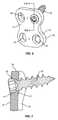
- FIG. 1is a schematic perspective view of a fastener and implant positioned at a bone according to one embodiment of the present application.
- FIG. 2is a perspective view of a fastener positioned in a passage through an implant according to one embodiment.
- FIG. 3is a sectional view cut along line III-III of FIG. 2 .
- FIG. 4is a perspective view of an implant according to one embodiment.
- FIG. 5is a sectional view cut along line V-V of FIG. 4 .
- FIG. 6is a perspective view of a fastener positioned in a passage through an implant according to one embodiment.
- FIG. 7is a sectional view cut along line VII-VII of FIG. 6 .
- FIG. 8is a sectional view of a passage through an implant according to one embodiment.
- FIG. 9is a sectional view of a passage through an implant according to one embodiment.
- FIG. 10is a sectional view of a passage through an implant according to one embodiment.
- FIG. 11is a sectional view of a passage through an implant according to one embodiment.
- FIG. 12is a side view of a fastener according to one embodiment.
- FIG. 13is a side schematic view of the fastener of FIG. 12 .
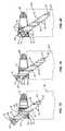
- FIG. 14is a sectional view of a fastener inserted a first amount into a bone according to one embodiment.
- FIG. 15is a sectional view of a fastener inserted a second amount into a bone according to one embodiment.
- FIG. 16is a sectional view of a fastener inserted a third amount into a bone according to one embodiment.
- FIG. 17is a sectional view of a fastener according to one embodiment.
- FIG. 18is a sectional view of a fastener inserted a first amount into a bone according to one embodiment.
- FIG. 19is a sectional view of a fastener inserted a second amount into a bone according to one embodiment.
- FIG. 20is a sectional view of a fastener inserted a third amount into a bone according to one embodiment.
- FIG. 21is a side view of a fastener according to one embodiment.
- FIG. 22is a side view of a fastener according to one embodiment.
- FIG. 23is a side view of a fastener according to one embodiment.
- FIG. 24is a side view of a fastener according to one embodiment.
- FIG. 25is a sectional view of an insert attached to an implant according to one embodiment.
- FIG. 26is a sectional view of a coating applied to an implant according to one embodiment.
- the present applicationis directed to an implant with a self-locking bone fastener that attaches the implant to a bone.
- the implantincludes a passage to receive the fastener.
- Sidewalls of the implant and the fastenerinclude different hardnesses causing one to be modified when the fastener is inserted into the implant. The modification causes an interference fit between the fastener and implant to prevent backout of the fastener.
- FIG. 1schematically illustrates a fastener 20 sized to fit within a passage 40 in an implant 30 .
- the fastener 20functions to extend through the passage 40 and attach the implant 30 to the bone 100 .
- the fastener 20includes an interference section 72 with a larger diameter than an interference section 70 of the passage 40 .
- the fastener 20is also constructed of a material with a different hardness than the interference section 70 .
- One of the interference sections 70 , 72is modified as the fastener 20 passes into the passage 40 and creates an interference fit. The interference fit at least prevents the fastener 20 from backing out of the bone 100 after attachment of the implant 30 .
- FIGS. 2 and 3include the implant 30 as a spacer configured to be positioned within an intervertebral space formed between vertebral members.
- the implant 30includes a superior surface 31 configured to contact against a first vertebral member and an inferior surface 32 configured to contact against a second vertebral member. Teeth 39 may extend outward from one or both of the surfaces 31 , 32 to facilitate insertion into the intervertebral space and/or maintain the position within the intervertebral space.
- a sidewall 33extends between the surfaces 31 , 32 .
- the height of the spacer measured between the surfaces 31 , 32may be constant, or may vary as best illustrated in FIG. 3 with the height increasing from a first lateral sidewall 61 to a second lateral sidewall 62 .
- a central passage 63may extend through spacer and through the surfaces 31 , 32 .
- Implant 30may also include an artificial disc as illustrated in FIGS. 4 and 5 .
- the implant 30includes a first member 64 and a second member 65 configured to be positioned within the intervertebral space formed between vertebral members.
- the first member 64includes a superior surface 31 configured to contact against the first vertebral member, and an inferior surface 32 is formed on a second member 65 to contact against the second vertebral member.
- the first member 64also includes a convex section 34 that extends outward and mates with a concave section 35 in the second member 65 .
- the convex and concave sections 34 , 35form a ball-and-socket arrangement that forms the artificial disc.
- Flanges 36are positioned on the members 64 , 65 and include passages 40 each sized to receive a fastener 20 .
- Each of the flanges 36 and passages 40may include different shapes, sizes, and orientations, or each may be substantially the same as best illustrated in FIG. 4 .
- the passages 40align with an exterior of the first and second vertebral members when the convex and concave sections 34 , 35 are positioned within the intervertebral space.
- the implant 30does not include flanges 36 and the passages 40 extend directly through the first and second members 64 , 65 in a similar manner as illustrated in FIGS. 2 and 3 .
- Implant 30may also include a plate as illustrated in FIGS. 6 and 7 .
- the plateincludes a first surface 31 that faces away from the bone 100 and a second surface 32 that faces towards and contacts against the bone 100 .
- Sidewalls 33extend between the first and second surfaces 31 , 32 .
- the platemay be substantially flat or may be curved.
- the thickness measured between the surfaces 31 , 32may be the same throughout the plate or may vary.
- One or more passages 40extend through the plate from the first surface 31 to the second surface 32 .
- One or more of the passages 40may also be positioned at least partially through the sidewalls 33 .
- the implant 30is constructed of a material with a different hardness than the fastener 20 . This difference causes the implant 30 to modify or be modified by the fastener 20 during insertion and create an interference fit that prevents backout of the fastener 20 .
- Implant materialsinclude but are not limited to polyaryletherketone (PAEK), polyetheretherketone (PEEK), carbon-reinforced PEEK, polyetherketoneketone (PEKK), polysulfone, polyetherimide, polyimide, ultra-high molecular weight polyethylene (UHMWPE), plastics, titanium, titanium alloy, stainless steel, and metallic alloys.
- a passage 40extends through the implant 30 to receive the fastener 20 .
- the passage 40generally includes a first end 41 and a second end 42 with a length L measured along an axis C between the first and second ends 41 , 42 .
- Passage 40further includes sidewalls 43 that extend between the ends 41 , 42 .
- a diameter Wis measured across the passage 40 between the sidewalls 43 . The diameter W may vary along the length L.
- FIG. 8includes a diameter W that is wider at the first end 41 than the second end 42 . The wider diameter W at the first end 41 forms a receptacle for seating a head 25 of the fastener 20 within the passage 40 as illustrated in FIGS. 2 and 3 .
- FIG. 9includes another passage 40 with a constant diameter W along the entire length L.
- the passage 40may extend through the implant 30 at various orientations.
- FIGS. 2 and 3include the passage 40 angled relative to the superior and inferior surfaces 31 , 32 with an axis neither parallel nor perpendicular to the surfaces 31 , 32 .
- the first end 41extends through both the superior surface 31 and sidewall 33 and the second end 42 extends through the inferior surface 32 .
- the amount of the angle relative to the superior and inferior surfaces 31 , 32may vary depending upon the context of use.
- Other configurations as illustrated in FIG. 9include an angled orientation with the first end 41 of the passage 40 being isolated to just within the sidewall 33 .
- FIGS. 4-7include the passage 40 extending more directly through the implant 30 between opposing surfaces.
- the passage 40includes an interference section 70 that is interacts with the fastener 20 during insertion.
- the interference section 70includes a diameter W′ that is narrower than the diameter W.
- the interference section 70may include different shapes and lengths.
- FIG. 8includes the interference section 70 extending along a limited distance of the length L, and specifically in proximity to the second surface 32 .
- FIG. 9includes the interference section 70 extending the entire length L of the passage 40 as the diameter W is constant along the length L (i.e., W equals W′).
- the interference section 70may be symmetrical about the axis C.
- FIGS. 8 and 9each include symmetrical interference sections 70 .
- the interference section 70may also include various other configurations.
- FIG. 10includes an extension on one of the sidewalls 43 that forms the interference section 70 .
- the passage 40may also include multiple interference sections 70 .
- FIG. 11includes three interference sections 70 a , 70 b , 70 c .
- the multiple sections 70may each include the same or different shapes and/or diameters W′.
- the interference section 70includes a solid surface that engages the fastener 20 .
- the implant 30includes a unitary one-piece construction. Therefore, the interference section 70 is constructed from the same material and from the same single structure as the remainder of the implant 30 .
- the interference section 70is formed by an insert 80 that is attached to the implant 30 .
- the insert 70forms the passage 40 and the interference section 70 .
- the insert 70may be attached to the implant 30 in various manners, including but not limited to interference fit, thread fit, mechanical fasteners, and adhesive.
- Another embodimentincludes a coating 81 applied to the sidewalls 43 of the passage 40 as illustrated in FIG. 26 . The coating 81 reduces a width of the passage 40 and creates the interference section 70 .
- the passage 40may include a circular shape when viewed along the axis C. However, passage 40 may also include other shapes including but not limited to oval, rectangular, square, and elliptical.
- the term diameteris used to define the distance across the passage 40 between the sidewalls 43 and should be construed in a manner to also apply to passages that are not circular.
- the fastener 20functions to extend through the passage 40 and attach the implant 30 to the bone 100 .
- Fastener 20may include various shapes and configurations to perform this function.
- Fastener 20may be constructed from a variety of materials, including but not limited to titanium, titanium alloy, stainless steel, metallic alloys, polyaryletherketone (PAEK), polyetheretherketone (PEEK), carbon-reinforced PEEK, polyetherketoneketone (PEKK), polysulfone, polyetherimide, polyimide, ultra-high molecular weight polyethylene (UHMWPE), and plastics.
- PEEKpolyaryletherketone
- PEEKpolyetheretherketone
- PEKKpolyetherketoneketone
- polysulfonepolyetherimide
- polyimidepolyimide
- UHMWPEultra-high molecular weight polyethylene
- FIG. 12illustrates a fastener 20 with an elongated shape that extends along a longitudinal axis L and generally includes a shank 22 and a head 25 .
- the fastener 20includes a distal tip 23 at an end of the shank 22 and an opposing proximal end 24 at the head 25 .
- the distal tip 23is preferably tapered to a point to facilitate movement through the bone 100 , although the tip 23 may include other non-tapered configurations.
- the length of the body 20 measured between the tip 23 and end 24may vary.
- the fastener 20may include one or more helical threads 21 that wrap around the longitudinal axis and extend along the shank 22 and/or head 25 .
- the thread 21may extend along the entire length of the fastener 20 , or just along a limited length.
- the thread 21defines a root 28 in proximity to the longitudinal axis L and a crest 29 distanced from the longitudinal axis L.
- the fastener 20includes a minor diameter di measured between the roots 28 , and a major diameter do measured between the crests 29 . One or both of the diameters di, do may be constant or may vary along the length of the fastener 20 .
- the crests 29may be tapered to facilitate self-tapping, or may be truncated and substantially flat.
- the crests 29may be constant or may vary along the length of the thread 21 .
- the thread 21includes a depth measured from the root 28 to the crest 29 .
- FIG. 12includes the thread depth being consistent along the length the shank 22 . The depth may also vary along the length as necessary.
- the thread 21may also include the same or different angles and/or pitch along the length.
- FIG. 12includes the thread angle and pitch being the same along the length of the thread 21 .
- a receptacle 26may extend into the head 25 to receive a tool for applying torque to the fastener 20 .
- the receptacle 26may include a variety of shapes to receive a tool with a variety of drive types including but not limited to slotted, Phillips, hexagonal, Torx, spline drive, and double hex.
- the cross-sectional shape of the head 25may also vary, including but not limited to pan head, button, round, countersunk, and oval.
- the head 25may further include the same size and shape as the shank 22 .
- the cross-sectional shape of the shank 22may be circular or may also be other shapes. The term diameter is again used and applies to these various shapes.
- One or more self-tapping flutes 27may be positioned at the distal tip 23 .
- the flutes 27are non-threaded and extend into the shank 22 to facilitate insertion and movement through the bone 100 .
- Fastener 20also includes an interference section 72 that extends along a longitudinal section of the length.
- the interference section 72includes a greater diameter than the diameter W′ of the interference section 70 of the passage 40 . This difference in size causes the interference section 72 to contact against and modify or be modified by the interference section 70 to create an interference fit between the fastener 20 and the implant 30 .
- just the thread 21creates the interference section 72 .
- Other embodimentsinclude the central body of the shank 22 formed the interference section 72 .
- the length L of the interference section 72 measured along the longitudinal axis Lmay vary.
- FIG. 13illustrates a theoretical side view of the screw of FIG. 12 .
- the dashed lines extending along the shank 22illustrate the minor diameter di defined by the roots 28
- the solid lines 29illustrate major diameter do defined by the crests 29 .
- FIG. 13includes the solid lines of the crests 29 parallel to the dashed lines of the roots 28 as the thread depth is the same along the length of the shank 22 .
- the fastener 20includes one or more longitudinal sections 50 each extending along a length of the longitudinal axis L.
- the sections 50may include constant or varying diameters di, do.
- a first section 51extends inward from the distal tip 23 .
- the fastener of FIG. 13includes a first section 51 with a tapered shape that widens in a proximal direction away from the tip 23 .
- the thread 21may or may not extend along the first section 51 . In one embodiment, the thread 21 begins along the first section 51 .
- Second and fourth sections 52 , 54are positioned along the shank 22 and each includes a tapered shape that increases towards the proximal end of the fastener 20 .
- the tapersmay be the same or may be different.
- Sections 52 , 54each include a linear taper. Tapers may also be non-linear (i.e., curved taper).
- FIG. 13includes the fourth section 54 with a sharper taper than the second section 52 .
- Third and fifth sections 53 , 55each include constant diameters di, do along their lengths.
- the interference section 72is formed by a portion of the fourth section 54 and the fifth section 55 in the fastener 20 of FIG. 13 . Positioning a starting edge 73 (i.e., distal edge) of the interference section 72 facilitates modifying of one of the interference sections 70 , 72 .
- FIGS. 14-16illustrate the steps of attaching the implant 30 to a bone 100 with the fastener 20 .
- the passage 40 in this embodimentfeatures a wide first end 41 that tapers down and leads into the interference section 70 .
- the fastener 20is inserted through the passage 40 with the distal tip 23 contacting against the bone 100 .
- the threads 21are engaging the bone 100 but are not contacting against the sidewalls 43 of the passage 40 .
- the interference section 72 of the fastener 20is positioned away from the interference section 70 of the passage 40 .
- FIG. 15illustrates the fastener 20 inserted a further distance into the bone 100 .
- the threads 21 at the interference section 72are in contact with the interference section 70 .
- the implant 30is constructed of a softer material than the fastener 20 .
- the sidewalls 43are solid and substantially smooth and not pre-tapped.
- the interference section 72modifies the interference section 70 and creates an interference fit.
- the interference section 72may be self-tapping as it cuts the sidewalls 43 , or may be thread-forming as it deforms the sidewalls 43 .
- the interference section 72is distanced away from the head 25 for modifying to occur prior to the head 25 bottoming out in the passage 40 .
- FIG. 16illustrates the fastener 20 fully inserted into the bone 100 .
- the amount of insertionis controlled by the head 25 contacting against the passage 40 .
- the head 25 and passage 40are configured for the head 25 to fit within and be recessed within the passage 40 .
- the interference section 72remains engaged with the interference section 70 with this contact forming the interference fit to prevent fastener 20 backout.
- FIGS. 14-16may also be used with the fastener 20 constructed of a softer material than the implant 30 .
- the interference section 72 of the fastener 20is modified by the interference section 70 . This may include just the thread 21 be modified as it moves past the interference section 70 , or may also include modification of the main body of the shank 22 .
- FIG. 17includes a fastener 20 with a first longitudinal section 51 that includes the distal tip 23 , a second threaded longitudinal section 52 , and a third longitudinal section 57 each being positioned distally from the head 25 .
- the second longitudinal section 52includes a gradually tapering shape with the diameters di, do increasing towards the proximal end.
- the interference section 72is positioned at the proximal end of the second section 52 .
- a thread 21extends along the length of the section 52 .
- Section 57is positioned between the interference section 72 and a distal edge of the head 25 .
- the longitudinal section 57is non-threaded and includes a diameter dm that is smaller than the major diameter do of the interference section 72 .
- FIGS. 18-20illustrate the steps of attaching the implant 30 to the bone 100 with this fastener 20 . These steps include the fastener 20 constructed of a harder material than the implant 30 .
- FIG. 18includes the fastener 20 inserted a first amount with the first section 51 and a portion of the second section 52 extending into the bone 100 . The diameter of the portion of the second section 52 within the passage 40 is smaller than the passage 40 with the thread 21 spaced from the sidewall 43 .
- FIG. 19illustrates the fastener 20 inserted a greater distance into the bone 100 .
- the interference section 72contacts against and modifies the interference section 70 .
- the sidewall 43is solid and is not pre-tapped.
- the interference section 72is spaced a distance from the head 25 to modify the interference section 70 prior to the head 25 being seated in the implant 30 .
- FIG. 20illustrates the fastener 20 fully inserted into the bone 100 .
- the head 25is bottomed out in the passage 40 and in contact with the sidewall 43 .
- the interference section 72has moved beyond the interference section 70 .
- the interference section 72is moved beyond the second end 42 of the passage 40 and into the bone 100 .
- the fastener 20is prevented from backing out of the bone 100 as the threads 21 no longer align with the contours that were formed in the interference section 70 . Therefore, any potential movement out of the bone 100 is prevented as the thread 21 on the interference section 72 contacts against the implant 30 .
- FIG. 20also illustrates that the longitudinal section 57 does not contact against the sidewall 43 .
- the fastener 20may be constructed such that the interference section 72 may move longitudinally beyond the interference section 70 but remain within the passage 40 .
- FIGS. 18-20may also be performed with the implant 30 be constructed from a harder material than the fastener 20 .
- the fastener 20is modified as it is inserted through the passage 40 .
- the interference section 72is modified by the contact with the interference section 70 .
- Fasteners 20may include other configurations to interact with the interference section 70 and attach the implant 30 to the bone 100 .
- FIG. 21includes a fastener 20 with a first thread 21 a extending along a first section 51 , and a second thread 21 b extending along second and third sections 52 , 53 .
- the threads 21 a , 21 bmay include one or more different aspects, including outer diameters, thread angle, and pitches.
- the interference section 72is formed by a portion of the second section 52 and the third section 53 .
- the first thread 21 ais configured to attach to the bone 100
- the second thread 21 bis configured to engage with and modify or be modified by the interference section 70 .
- Fasteners 20may also include more than two different threads 21 . Examples of multiple thread fasteners 20 are disclosed in US Patent Publication No. 2007/0233122 herein incorporated by reference in its entirety.
- the interference section 72may also be formed along a non-threaded section of the fastener 20 .
- FIG. 22includes a fastener 20 with a first section 51 , threaded second section 52 , and non-threaded third and fourth sections 53 , 54 .
- the interference section 72is formed by the fourth section 54 with the distal edge formed at the intersection of the third and fourth sections 53 , 54 .
- FIG. 23includes a fastener 20 with the interference section 72 formed by the second section 52 .
- a series of engagement features 74are positioned in the second section 52 .
- the engagement features 74may include grooves that are cut into the main body of the shank 22 .
- the groovesmay be longitudinal, radial, or helical.
- Engagement features 74may also include protrusions that extend outward from the surface of the main body of the shank 22 .
- the engagement features 74facilitate engagement with the interference section 70 and/or inhibit further rotation that could cause backout of the fastener 20 .
- one or more flutes 27are positioned proximal to the interference section 72 .
- Fastener 20may also include multiple modifying sections 72 located along the length.
- FIG. 24includes an embodiment with a first interference section 72 a located along a second section 52 , and a second interference section 72 b located along the fourth section 54 .
- the first interference section 72 aincludes a thread 21 and is sized to initially modify or be modified by the interference section 70 .
- the second interference section 72 bis positioned proximally from the first interference section 72 a .
- the second interference section 72 bis also sized to contact against the interference section 70 .
- the second interference section 72 bincludes a larger diameter than the first interference section 72 a.
- the first interference section 72 amoves through the passage 40 and modifies or is modified by the interference section 70 .
- Further insertion of the fastener 20moves the second interference section 72 b into the interference section 70 and results in further modification.
- the fastener 20may include a size for a double interference fit with the first interference section 72 a moving beyond the interference section 70 and modifying or being modified by the interference section 70 to prevent backout.
- the second interference section 72 bmay remain in the interference section 70 and form a second interference fit.
- the fastener 20may further include more than two separate modifying sections 72 .
- the various fasteners 20 used to attach the implant 30 to the bone 100may include different structures.
- the fasteners 20 described aboveinclude different combinations of these structures.
- the various interference sections 70 , tapers, longitudinal sections 50 , diameters di, do, threads 21 , heads 25 , tips 23 , receptacles 26 , etc.may be combined in a variety of different combinations within a fastener 20 depending upon the context of use and are included within the scope of the present application.
- the modification of one of the interference sections 70 , 72creates the interference fit that prevents backout.
- the modificationmay include a self-tapping engagement as material is cut to form threads on the softer interference section 70 , 72 .
- the modificationmay also include thread-forming engagement caused by deformation of the softer interference section 70 , 72 .
- the modificationmay also include a variety of other deforming, cutting, and otherwise general altering of the softer interference section 70 , 72 .
- the modifications caused by the engagement between the sections 70 , 72are permanent.
- the implants 10may include more than one passage 40 and be attached to the bone 100 by more than one fastener 20 .
- at least one of the passages 40includes an interference section 70 that is modified by a fastener 20 .
- the other passages 40may or may not include an interference section 70 .
- each of the passages 40may include the same or different structure.
- the fasteners 20may each be the same or one or more may be different.
- the implants 30may be attached to a variety of different bones 100 within the patient. These include the vertebrae as well as the long bone of the patient.
- the implant 30is constructed of PEEK and the fastener 20 is constructed of titanium.
- the sidewalls 43 of the passage 30are solid and non-threaded.
- the implants 30may be implanted within a living patient for the treatment of various spinal disorders.
- the implants 30may also be implanted in a non-living situation, such as within a cadaver, model, and the like.
- the non-living situationmay be for one or more of testing, training, and demonstration purposes.
Landscapes
- Health & Medical Sciences (AREA)
- Orthopedic Medicine & Surgery (AREA)
- Life Sciences & Earth Sciences (AREA)
- Engineering & Computer Science (AREA)
- Biomedical Technology (AREA)
- Neurology (AREA)
- Surgery (AREA)
- General Health & Medical Sciences (AREA)
- Veterinary Medicine (AREA)
- Heart & Thoracic Surgery (AREA)
- Public Health (AREA)
- Animal Behavior & Ethology (AREA)
- Molecular Biology (AREA)
- Medical Informatics (AREA)
- Nuclear Medicine, Radiotherapy & Molecular Imaging (AREA)
- Cardiology (AREA)
- Oral & Maxillofacial Surgery (AREA)
- Transplantation (AREA)
- Vascular Medicine (AREA)
- Prostheses (AREA)
- Surgical Instruments (AREA)
Abstract
Description
The present application is directed to an implant attached to a bone with a fastener and, more particularly, to a fastener and an implant with different hardnesses with one being modified during insertion of the fastener through a passage in the implant to create an interference fit.
Various types of implants are inserted into a patient and attached with a fastener to a bone. The fastener extends through the implant and into the bone maintaining the implant against the bone. The fastener may also be configured to apply a compressive force against the implant. The implant and fastener should be structured to prevent the fastener from being non-threaded or otherwise removed from the bone and/or implant. This backward movement of the fastener relative to the bone and/or implant is referred to as backout. Backout may be caused by subsidence of the bone after attachment of the implant, or unthreading of the fastener from the bone.
Mechanisms have been developed to prevent backout of a fastener. One type of mechanism includes a snap ring that attaches to the implant and extends over a passage through the implant that receives the fastener. The snap ring is contacted during insertion of the fastener causing the snap ring to move away from the passage to allow insertion. Once the fastener passes, the snap-ring rebounds over the passage and head of the fastener. Drawbacks of these mechanisms include that the snap ring may become detached from the implant, and the snap ring may not rebound over the fastener. Further, a surgeon may have difficulty determining the position of the snap ring during a surgical procedure.
Another mechanism includes a projection that is movable by the surgeon between a locked orientation that extends over the passage in the implant and an unlocked orientation away from the passage. The projection is in the unlocked orientation when the fastener is inserted into the passage and driven into the bone. After insertion, the projection is moved by the surgeon to the locked orientation over the passage and the proximal end of the fastener. A drawback of this design is it requires the surgeon to perform an additional step after insertion of the fastener. It may also be difficult for a surgeon to determine that the projection is properly positioned over the fastener.
The present application is an implant that attaches to a bone and methods of using the implant. The implant may include a passage with a first end and second end. The passage may include a first interference section between the first and second ends. A fastener with an elongated shape may be sized to extend through the passage to attach the implant to the bone. The fastener may include a second interference section. During insertion of the fastener through the passage and into the bone, the second interference section of the fastener may contact against and modify or be modified by the first interference section of the passage. This modification may create an interference fit between the implant and the fastener that prevents backout. The first and second interference sections may remain in contact once the fastener is fully attached to the bone, or may move apart.
The various aspects of the various embodiments may be used alone or in any combination, as is desired.
The present application is directed to an implant with a self-locking bone fastener that attaches the implant to a bone. The implant includes a passage to receive the fastener. Sidewalls of the implant and the fastener include different hardnesses causing one to be modified when the fastener is inserted into the implant. The modification causes an interference fit between the fastener and implant to prevent backout of the fastener.
Theimplant 30 is attached to thebone 100 by one ormore fasteners 20 and may include a variety of shapes and configurations.FIGS. 2 and 3 include theimplant 30 as a spacer configured to be positioned within an intervertebral space formed between vertebral members. Theimplant 30 includes asuperior surface 31 configured to contact against a first vertebral member and aninferior surface 32 configured to contact against a second vertebral member.Teeth 39 may extend outward from one or both of thesurfaces sidewall 33 extends between thesurfaces surfaces FIG. 3 with the height increasing from a firstlateral sidewall 61 to a secondlateral sidewall 62. Acentral passage 63 may extend through spacer and through thesurfaces
Theimplant 30 is constructed of a material with a different hardness than thefastener 20. This difference causes theimplant 30 to modify or be modified by thefastener 20 during insertion and create an interference fit that prevents backout of thefastener 20. Implant materials include but are not limited to polyaryletherketone (PAEK), polyetheretherketone (PEEK), carbon-reinforced PEEK, polyetherketoneketone (PEKK), polysulfone, polyetherimide, polyimide, ultra-high molecular weight polyethylene (UHMWPE), plastics, titanium, titanium alloy, stainless steel, and metallic alloys.
Apassage 40 extends through theimplant 30 to receive thefastener 20. As illustrated inFIG. 8 , thepassage 40 generally includes afirst end 41 and asecond end 42 with a length L measured along an axis C between the first and second ends41,42.Passage 40 further includessidewalls 43 that extend between theends passage 40 between the sidewalls43. The diameter W may vary along the length L.FIG. 8 includes a diameter W that is wider at thefirst end 41 than thesecond end 42. The wider diameter W at thefirst end 41 forms a receptacle for seating ahead 25 of thefastener 20 within thepassage 40 as illustrated inFIGS. 2 and 3 .FIG. 9 includes anotherpassage 40 with a constant diameter W along the entire length L.
Thepassage 40 may extend through theimplant 30 at various orientations.FIGS. 2 and 3 include thepassage 40 angled relative to the superior andinferior surfaces surfaces first end 41 extends through both thesuperior surface 31 andsidewall 33 and thesecond end 42 extends through theinferior surface 32. The amount of the angle relative to the superior andinferior surfaces FIG. 9 include an angled orientation with thefirst end 41 of thepassage 40 being isolated to just within thesidewall 33.FIGS. 4-7 include thepassage 40 extending more directly through theimplant 30 between opposing surfaces.
Thepassage 40 includes aninterference section 70 that is interacts with thefastener 20 during insertion. In one embodiment as illustrated inFIG. 8 , theinterference section 70 includes a diameter W′ that is narrower than the diameter W. Theinterference section 70 may include different shapes and lengths.FIG. 8 includes theinterference section 70 extending along a limited distance of the length L, and specifically in proximity to thesecond surface 32.FIG. 9 includes theinterference section 70 extending the entire length L of thepassage 40 as the diameter W is constant along the length L (i.e., W equals W′).
Theinterference section 70 may be symmetrical about the axis C.FIGS. 8 and 9 each includesymmetrical interference sections 70. Theinterference section 70 may also include various other configurations.FIG. 10 includes an extension on one of the sidewalls43 that forms theinterference section 70. Thepassage 40 may also includemultiple interference sections 70.FIG. 11 includes threeinterference sections multiple sections 70 may each include the same or different shapes and/or diameters W′.
Theinterference section 70 includes a solid surface that engages thefastener 20. In one embodiment, theimplant 30 includes a unitary one-piece construction. Therefore, theinterference section 70 is constructed from the same material and from the same single structure as the remainder of theimplant 30. In another embodiment as illustrated inFIG. 25 , theinterference section 70 is formed by aninsert 80 that is attached to theimplant 30. Theinsert 70 forms thepassage 40 and theinterference section 70. Theinsert 70 may be attached to theimplant 30 in various manners, including but not limited to interference fit, thread fit, mechanical fasteners, and adhesive. Another embodiment includes acoating 81 applied to thesidewalls 43 of thepassage 40 as illustrated inFIG. 26 . Thecoating 81 reduces a width of thepassage 40 and creates theinterference section 70.
Thepassage 40 may include a circular shape when viewed along the axis C. However,passage 40 may also include other shapes including but not limited to oval, rectangular, square, and elliptical. The term diameter is used to define the distance across thepassage 40 between the sidewalls43 and should be construed in a manner to also apply to passages that are not circular.
Thefastener 20 functions to extend through thepassage 40 and attach theimplant 30 to thebone 100.Fastener 20 may include various shapes and configurations to perform this function.Fastener 20 may be constructed from a variety of materials, including but not limited to titanium, titanium alloy, stainless steel, metallic alloys, polyaryletherketone (PAEK), polyetheretherketone (PEEK), carbon-reinforced PEEK, polyetherketoneketone (PEKK), polysulfone, polyetherimide, polyimide, ultra-high molecular weight polyethylene (UHMWPE), and plastics.
Thefastener 20 may include one or morehelical threads 21 that wrap around the longitudinal axis and extend along theshank 22 and/orhead 25. Thethread 21 may extend along the entire length of thefastener 20, or just along a limited length. Thethread 21 defines aroot 28 in proximity to the longitudinal axis L and acrest 29 distanced from the longitudinal axis L. Thefastener 20 includes a minor diameter di measured between theroots 28, and a major diameter do measured between thecrests 29. One or both of the diameters di, do may be constant or may vary along the length of thefastener 20.
Thecrests 29 may be tapered to facilitate self-tapping, or may be truncated and substantially flat. Thecrests 29 may be constant or may vary along the length of thethread 21. Thethread 21 includes a depth measured from theroot 28 to thecrest 29.FIG. 12 includes the thread depth being consistent along the length theshank 22. The depth may also vary along the length as necessary. Thethread 21 may also include the same or different angles and/or pitch along the length.FIG. 12 includes the thread angle and pitch being the same along the length of thethread 21.
Areceptacle 26 may extend into thehead 25 to receive a tool for applying torque to thefastener 20. Thereceptacle 26 may include a variety of shapes to receive a tool with a variety of drive types including but not limited to slotted, Phillips, hexagonal, Torx, spline drive, and double hex.
The cross-sectional shape of thehead 25 may also vary, including but not limited to pan head, button, round, countersunk, and oval. Thehead 25 may further include the same size and shape as theshank 22. The cross-sectional shape of theshank 22 may be circular or may also be other shapes. The term diameter is again used and applies to these various shapes.
One or more self-tappingflutes 27 may be positioned at thedistal tip 23. Theflutes 27 are non-threaded and extend into theshank 22 to facilitate insertion and movement through thebone 100.
Thefastener 20 includes one or more longitudinal sections50 each extending along a length of the longitudinal axis L. The sections50 may include constant or varying diameters di, do. Afirst section 51 extends inward from thedistal tip 23. The fastener ofFIG. 13 includes afirst section 51 with a tapered shape that widens in a proximal direction away from thetip 23. Thethread 21 may or may not extend along thefirst section 51. In one embodiment, thethread 21 begins along thefirst section 51. Second andfourth sections shank 22 and each includes a tapered shape that increases towards the proximal end of thefastener 20. The tapers may be the same or may be different.Sections FIG. 13 includes thefourth section 54 with a sharper taper than thesecond section 52. Third andfifth sections
In this embodiment, theinterference section 72 is formed by a portion of thefourth section 54 and thefifth section 55 in thefastener 20 ofFIG. 13 . Positioning a starting edge73 (i.e., distal edge) of theinterference section 72 facilitates modifying of one of theinterference sections
The embodiment ofFIGS. 14-16 may also be used with thefastener 20 constructed of a softer material than theimplant 30. As thefastener 20 moves through thepassage 40, theinterference section 72 of thefastener 20 is modified by theinterference section 70. This may include just thethread 21 be modified as it moves past theinterference section 70, or may also include modification of the main body of theshank 22.
The embodiment ofFIGS. 18-20 may also be performed with theimplant 30 be constructed from a harder material than thefastener 20. Thefastener 20 is modified as it is inserted through thepassage 40. Theinterference section 72 is modified by the contact with theinterference section 70.
Theinterference section 72 may also be formed along a non-threaded section of thefastener 20.FIG. 22 includes afastener 20 with afirst section 51, threadedsecond section 52, and non-threaded third andfourth sections interference section 72 is formed by thefourth section 54 with the distal edge formed at the intersection of the third andfourth sections FIG. 23 includes afastener 20 with theinterference section 72 formed by thesecond section 52. A series of engagement features74 are positioned in thesecond section 52. The engagement features74 may include grooves that are cut into the main body of theshank 22. The grooves may be longitudinal, radial, or helical. Engagement features74 may also include protrusions that extend outward from the surface of the main body of theshank 22. The engagement features74 facilitate engagement with theinterference section 70 and/or inhibit further rotation that could cause backout of thefastener 20. In a similar embodiment, one ormore flutes 27 are positioned proximal to theinterference section 72.
During insertion of thefastener 20 into thepassage 40, thefirst interference section 72amoves through thepassage 40 and modifies or is modified by theinterference section 70. Further insertion of thefastener 20 moves thesecond interference section 72binto theinterference section 70 and results in further modification. Thefastener 20 may include a size for a double interference fit with thefirst interference section 72amoving beyond theinterference section 70 and modifying or being modified by theinterference section 70 to prevent backout. Thesecond interference section 72bmay remain in theinterference section 70 and form a second interference fit. Thefastener 20 may further include more than two separate modifyingsections 72.
Thevarious fasteners 20 used to attach theimplant 30 to thebone 100 may include different structures. Thefasteners 20 described above include different combinations of these structures. Thevarious interference sections 70, tapers, longitudinal sections50, diameters di, do,threads 21, heads25,tips 23,receptacles 26, etc. may be combined in a variety of different combinations within afastener 20 depending upon the context of use and are included within the scope of the present application.
The modification of one of theinterference sections softer interference section softer interference section softer interference section sections
The implants10 may include more than onepassage 40 and be attached to thebone 100 by more than onefastener 20. In these embodiments, at least one of thepassages 40 includes aninterference section 70 that is modified by afastener 20. Theother passages 40 may or may not include aninterference section 70. Further, withimplants 30 withmultiple passages 40, each of thepassages 40 may include the same or different structure. Likewise, thefasteners 20 may each be the same or one or more may be different.
Theimplants 30 may be attached to a variety ofdifferent bones 100 within the patient. These include the vertebrae as well as the long bone of the patient.
In one embodiment, theimplant 30 is constructed of PEEK and thefastener 20 is constructed of titanium. Thesidewalls 43 of thepassage 30 are solid and non-threaded.
Theimplants 30 may be implanted within a living patient for the treatment of various spinal disorders. Theimplants 30 may also be implanted in a non-living situation, such as within a cadaver, model, and the like. The non-living situation may be for one or more of testing, training, and demonstration purposes.
Spatially relative terms such as “under”, “below”, “lower”, “over”, “upper”, and the like, are used for ease of description to explain the positioning of one element relative to a second element. These terms are intended to encompass different orientations of the device in addition to different orientations than those depicted in the figures. Further, terms such as “first”, “second”, and the like, are also used to describe various elements, regions, sections, etc and are also not intended to be limiting. Like terms refer to like elements throughout the description.
As used herein, the terms “having”, “containing”, “including”, “comprising” and the like are open ended terms that indicate the presence of stated elements or features, but do not preclude additional elements or features. The articles “a”, “an” and “the” are intended to include the plural as well as the singular, unless the context clearly indicates otherwise.
The present invention may be carried out in other specific ways than those herein set forth without departing from the scope and essential characteristics of the invention. The present embodiments are, therefore, to be considered in all respects as illustrative and not restrictive, and all changes coming within the meaning and equivalency range of the appended claims are intended to be embraced therein.
Claims (22)
1. A medical device for treating a patient comprising:
an implant having a maximum height defined by a distance between a superior surface and an inferior surface opposite the superior surface, and a length defined by a distance between first and second ends that extend between the superior and inferior surfaces, the height of the implant decreasing continuously from the first end to the second end;
a solid, non-threaded passage that extends from the superior surface through the implant to the inferior surface, the passage having a length defined by a distance between a first end having a first diameter and a second end having a second diameter, the first diameter wider than the second diameter, the first end extending through the superior surface and the second end adjacent to the inferior surface, the passage having a first portion that includes the first end, and a first interference section having a constant diameter width of the second diameter and including the second end;
a fastener with an elongated shape extending between a distal end and a proximal end, the fastener including an intermediate portion between the distal end and the proximal end, the proximal end and the intermediate portion each being free of threads, the distal end defining a second interference section extending along a length of the distal end and including a third diameter that is greater than the second diameter, the intermediate portion having a maximum diameter which is less than a maximum diameter of the distal end, the fastener comprising a helical thread extending continuously from a distal tip of the distal end to a proximal edge of the second interference section;
one of the first and second interference sections constructed from a harder material and the other constructed from a softer material;
a surface of the first interference section constructed from the softer material being modified by insertion of the fastener into the passage to create an interference fit between the implant and the fastener.
2. The device ofclaim 1 , wherein at least the first portion of the passage is tapered.
3. The device ofclaim 1 , wherein the passage extends at an acute angle relative to the superior and inferior surfaces.
4. The device ofclaim 1 , wherein the helical thread has a uniform pitch from the distal tip to the proximal edge.
5. The device ofclaim 1 , wherein the helical thread has a uniform depth from the distal tip to the proximal edge.
6. The device ofclaim 1 , wherein the proximal end of the fastener includes a head having a maximum diameter that is greater than the maximum diameter of the distal end.
7. The device ofclaim 1 , wherein:
the fastener comprises a first section with a tapered shape that widens in a proximal direction away from the distal tip;
second and fourth sections of the fastener are positioned along the distal end and each include a tapered shape that increases in diameter toward the proximal end, the second section extending from the first section; and
third and fifth sections of the fastener each include a constant diameter, the third section being positioned between the second and fourth sections and the fifth section extending from the fourth section.
8. The device ofclaim 7 , wherein the second and fourth sections each include a linear taper.
9. The device ofclaim 7 , wherein the second interference section is defined by a portion of the fourth section and a portion of the fifth section.
10. The device ofclaim 7 , wherein the second interference section is spaced apart from the third section.
11. The device ofclaim 1 , wherein the proximal end of the fastener includes a head comprising a receptacle configured to receive a tool for applying torque to the fastener.
12. A medical device for treating a patient comprising:
an implant having a maximum height defined by a distance between a superior surface and an inferior surface opposite the superior surface, and a length defined by a distance between first and second ends that extend between the superior and inferior surfaces, the height of the implant decreasing continuously from the first end to the second end;
a passage that extends from the superior surface through the implant to the inferior surface, the passage extending between a first end having a first diameter and a second end having a second diameter, the first diameter wider than the second diameter, the first end extending through the superior surface and the second end adjacent to the inferior surface, the passage having a first portion that includes the first end, and an interference section with solid non-threaded sidewalls, the interference section having a constant diameter width of the second diameter and including the second end;
a fastener with an elongated shape extending between a distal end and a proximal end, the fastener includes an intermediate portion between the distal end and the proximal end, the proximal end and the intermediate portion each being free of threads, the distal end defining a modifying section extending along a length of the distal end and including a third diameter that is greater than the second diameter, the intermediate portion having a maximum diameter which is less than a maximum diameter of the distal end, the fastener comprising a helical thread extending continuously from a distal tip of the distal end to a proximal edge of the second interference section;
the fastener constructed from a harder material than the implant with the modifying section modifying the interference section during insertion of the fastener into the passage and creating an interference fit between the implant and the fastener,
wherein the first portion of the passage has a tapered diameter.
13. The device ofclaim 12 , wherein the interference section is constructed from a material that is permanently modified by the modifying section.
14. The device ofclaim 12 , wherein the modifying section includes a tapered diameter that increases from a distal portion towards a proximal portion.
15. The device ofclaim 12 , wherein the implant is constructed from PEEK.
16. A medical device for treating a patient comprising:
an implant having a maximum height defined by a distance between a superior surface and an inferior surface opposite the superior surface and a length defined by a distance between first and second ends that extend between the superior and inferior surfaces, the height of the implant decreasing continuously from the first end to the second end;
a passage that extends from the superior surface through the implant to the inferior surface, the passage having a length defined by a distance between a first end having a first diameter and a second end having a second diameter, the first diameter wider than the second diameter, the first end extending through the superior surface and the second end adjacent to the inferior surface, the passage having a first portion that includes the first end and a first interference section with solid non-threaded sidewalls, the first interference section having a constant diameter width of the second a diameter and including the second end; and
a fastener with an elongated shape including a shank extending between a distal end having a distal tip and a proximal end, the fastener including an intermediate portion between the distal end and the proximal end, the proximal end and the intermediate portion each being free of threads, the distal end defining a second interference section extending along a length of the distal end and including a third diameter that is greater than the second diameter, the intermediate portion having a maximum diameter which is less than a maximum diameter of the distal end, the fastener comprising a helical thread extending continuously from the distal tip of the distal end to a proximal edge of the second interference section;
the first interference section constructed from a harder material than the second interference section with the second interference section being permanently modified during insertion of the fastener into the passage,
wherein the first portion of the passage has a tapered diameter,
and further wherein the fastener includes one or more self-tapping flutes positioned at the distal tip, the flutes being non-threaded and extending into the shank.
17. A medical device for treating a patient comprising:
an implant having a superior surface and an inferior surface opposite the superior surface, the implant comprising a non-threaded passage that extends between and through the superior surface and the inferior surface, the passage having a length defined by a distance between a first end having a first diameter and a second end having a second diameter, the first diameter wider than the second diameter, the passage having a first portion that includes the first end and a first interference section having a constant diameter width of the second diameter and including the second end; and
a fastener extending between a distal end and a proximal end that is free of threads, the distal end defining a second interference section extending along a length of the distal end and including a third diameter that is greater than the second diameter, the fastener comprising a helical thread extending continuously from a distal tip of the distal end to a proximal edge of the second interference section,
wherein the second interference section is constructed from a harder material and the first interference section is constructed from a softer material such that the first interference section is modified by insertion of the fastener into the passage to create an interference fit between the implant and the fastener,
wherein the fastener comprises a first section with a tapered shape that widens in a proximal direction away from the distal tip,
wherein second and fourth sections of the fastener are positioned along the distal end and each include a tapered shape that increases in diameter toward the proximal end, the second section extending from the first section,
wherein third and fifth sections of the fastener each include a constant diameter, the third section being positioned between the second and fourth sections and the fifth section extending from the fourth section, and
wherein the second interference section is defined by a portion of the fourth section and a portion of the fifth section.
18. A medical device for treating a patient comprising:
an implant having a superior surface and an inferior surface opposite the superior surface and first and second ends that each extend between the superior and inferior surfaces, the implant comprising a non-threaded passage that extends through and between the superior surface and the inferior surface, the passage having a first end having a first diameter and a second end having a second diameter, the first diameter being wider than the second diameter, the passage including a first interference section adjacent the second end having a constant diameter width of the second diameter; and
a fastener extending between a threaded distal end and a proximal end that is free of threads, the distal end defining a second interference section extending along a length of the distal end and including a third diameter that is greater than the second diameter,
wherein the second interference section is constructed from a harder material and the first interference section is constructed from a softer material such that the first interference section is modified by insertion of the fastener into the passage to create an interference fit between the implant and the fastener,
wherein the fastener comprises a first section with a tapered shape that widens in a proximal direction away from a distal tip of the distal end of the fastener,
wherein second and fourth sections of the fastener are positioned along the distal end of the fastener and each include a tapered shape that increases in diameter toward the proximal end of the fastener, the second section extending from the first section,
wherein third and fifth sections of the fastener each include a constant diameter, the third section being positioned between the second and fourth sections and the fifth section extending from the fourth section, and
wherein the second interference section is defined by a portion of the fourth section and a portion of the fifth section.
19. The device ofclaim 18 , wherein the fastener comprises a helical thread extending continuously from a distal tip of the distal end to a proximal edge of the second interference section.
20. The device ofclaim 18 , wherein the second and fourth sections each include a linear taper.
21. The device ofclaim 18 , wherein the second interference section is defined by a portion of the fourth section and a portion of the fifth section.
22. The device ofclaim 18 , wherein the second interference section is spaced apart from the third section.
Priority Applications (8)
| Application Number | Priority Date | Filing Date | Title |
|---|---|---|---|
| US12/508,669US9095444B2 (en) | 2009-07-24 | 2009-07-24 | Implant with an interference fit fastener |
| CA 2768669CA2768669A1 (en) | 2009-07-24 | 2010-07-26 | Implant with an interference fit fastener |
| EP20100742341EP2456378B1 (en) | 2009-07-24 | 2010-07-26 | Implant with an interference fit fastener |
| CN2010800382576ACN102481161A (en) | 2009-07-24 | 2010-07-26 | Implant with an interference fit fastener |
| JP2012521875AJP5865244B2 (en) | 2009-07-24 | 2010-07-26 | Implants using interference fit fasteners |
| PCT/US2010/043246WO2011011784A1 (en) | 2009-07-24 | 2010-07-26 | Implant with an interference fit fastener |
| AU2010275376AAU2010275376B2 (en) | 2009-07-24 | 2010-07-26 | Implant with an interference fit fastener |
| US14/751,939US9433453B2 (en) | 2009-07-24 | 2015-06-26 | Implant with an interference fit fastener |
Applications Claiming Priority (1)
| Application Number | Priority Date | Filing Date | Title |
|---|---|---|---|
| US12/508,669US9095444B2 (en) | 2009-07-24 | 2009-07-24 | Implant with an interference fit fastener |
Related Child Applications (1)
| Application Number | Title | Priority Date | Filing Date |
|---|---|---|---|
| US14/751,939DivisionUS9433453B2 (en) | 2009-07-24 | 2015-06-26 | Implant with an interference fit fastener |
Publications (2)
| Publication Number | Publication Date |
|---|---|
| US20110022173A1 US20110022173A1 (en) | 2011-01-27 |
| US9095444B2true US9095444B2 (en) | 2015-08-04 |
Family
ID=42988351
Family Applications (2)
| Application Number | Title | Priority Date | Filing Date |
|---|---|---|---|
| US12/508,669Active2031-11-22US9095444B2 (en) | 2009-07-24 | 2009-07-24 | Implant with an interference fit fastener |
| US14/751,939Active2029-09-08US9433453B2 (en) | 2009-07-24 | 2015-06-26 | Implant with an interference fit fastener |
Family Applications After (1)
| Application Number | Title | Priority Date | Filing Date |
|---|---|---|---|
| US14/751,939Active2029-09-08US9433453B2 (en) | 2009-07-24 | 2015-06-26 | Implant with an interference fit fastener |
Country Status (7)
| Country | Link |
|---|---|
| US (2) | US9095444B2 (en) |
| EP (1) | EP2456378B1 (en) |
| JP (1) | JP5865244B2 (en) |
| CN (1) | CN102481161A (en) |
| AU (1) | AU2010275376B2 (en) |
| CA (1) | CA2768669A1 (en) |
| WO (1) | WO2011011784A1 (en) |
Cited By (1)
| Publication number | Priority date | Publication date | Assignee | Title |
|---|---|---|---|---|
| US20220313328A1 (en)* | 2021-03-30 | 2022-10-06 | Wright Medical Technology, Inc. | Bone fixation implant and method of implantation |
Families Citing this family (8)
| Publication number | Priority date | Publication date | Assignee | Title |
|---|---|---|---|---|
| US9387022B2 (en) | 2012-06-27 | 2016-07-12 | DePuy Synthes Products, Inc. | Variable angle bone fixation device |
| US9265542B2 (en) | 2012-06-27 | 2016-02-23 | DePuy Synthes Products, Inc. | Variable angle bone fixation device |
| WO2014029033A1 (en)* | 2012-08-21 | 2014-02-27 | Montavon Lorraine | Clamping element and device for stabilizing bones |
| US10531900B2 (en) | 2014-04-17 | 2020-01-14 | Zimmer Biomet CMF and Thoracic, LLC | Contourable plate |
| US20160151166A1 (en)* | 2014-07-01 | 2016-06-02 | Alliance Partners, Llc | Low profile standalone cervical interbody with screw locking clips and method of using same |
| US11786343B2 (en) | 2020-07-09 | 2023-10-17 | Southern Implants (Pty) Ltd | Dental implants with stepped threads and systems and methods for making the same |
| EP4221638B1 (en)* | 2020-10-02 | 2025-09-24 | Facet Mobility, LLC | Artificial spinal prosthesis |
| DE102023102881B4 (en)* | 2023-02-07 | 2025-01-30 | Maxxspine Innovative Gmbh | cervical cage |
Citations (271)
| Publication number | Priority date | Publication date | Assignee | Title |
|---|---|---|---|---|
| US4657550A (en) | 1984-12-21 | 1987-04-14 | Daher Youssef H | Buttressing device usable in a vertebral prosthesis |
| US4834757A (en) | 1987-01-22 | 1989-05-30 | Brantigan John W | Prosthetic implant |
| US4838891A (en) | 1984-11-28 | 1989-06-13 | Branemark Per Ingvar | Joint prothesis |
| US4904261A (en) | 1987-08-06 | 1990-02-27 | A. W. Showell (Surgicraft) Limited | Spinal implants |
| US4955908A (en) | 1987-07-09 | 1990-09-11 | Sulzer Brothers Limited | Metallic intervertebral prosthesis |
| US5019079A (en) | 1989-11-20 | 1991-05-28 | Zimmer, Inc. | Bone screw |
| US5041113A (en) | 1989-07-20 | 1991-08-20 | Lutz Biedermann | Stabilization member for stabilizing bones |
| US5053036A (en) | 1987-11-03 | 1991-10-01 | Synthes (U.S.A.) | Point contact bone compression plate |
| US5067956A (en) | 1990-04-24 | 1991-11-26 | Smith & Nephew Richards Inc. | Apparatus for fastening a medical implant |
| US5085548A (en) | 1991-04-30 | 1992-02-04 | The United States Of America As Represented By The Secretary Of The Navy | Nut and snap ring position locking device |
| US5120171A (en) | 1990-11-27 | 1992-06-09 | Stuart Surgical | Bone screw with improved threads |
| US5127912A (en) | 1990-10-05 | 1992-07-07 | R. Charles Ray | Sacral implant system |
| US5147363A (en) | 1989-12-21 | 1992-09-15 | Haerle Anton | Screw for use in osteosynthesis |
| US5180382A (en) | 1990-12-19 | 1993-01-19 | Synthes (U.S.A.) | Bone screw |
| US5180381A (en) | 1991-09-24 | 1993-01-19 | Aust Gilbert M | Anterior lumbar/cervical bicortical compression plate |
| US5190544A (en) | 1986-06-23 | 1993-03-02 | Pfizer Hospital Products Group, Inc. | Modular femoral fixation system |
| US5192327A (en) | 1991-03-22 | 1993-03-09 | Brantigan John W | Surgical prosthetic implant for vertebrae |
| US5217462A (en) | 1991-03-05 | 1993-06-08 | Pfizer Hospital Products Group, Inc. | Screw and driver |
| US5226766A (en) | 1990-11-27 | 1993-07-13 | Stuart Surgical | Bone screw with improved threads |
| US5234430A (en) | 1991-12-18 | 1993-08-10 | Huebner Randall J | Orthopedic fixation screw and method |
| US5252016A (en) | 1989-11-13 | 1993-10-12 | Isolink Inc. | Fixing element for low strength materials |
| US5259398A (en) | 1989-10-26 | 1993-11-09 | Giuseppe Vrespa | Method for fixing prosthesis to bones |
| US5290312A (en) | 1991-09-03 | 1994-03-01 | Alphatec | Artificial vertebral body |
| US5300076A (en) | 1991-10-11 | 1994-04-05 | Societe De Fabrication De Materiel Orthopedique-Sofamore | Percutaneous bone screw for supporting a stereotaxy frame |
| US5300073A (en) | 1990-10-05 | 1994-04-05 | Salut, Ltd. | Sacral implant system |
| US5306309A (en) | 1992-05-04 | 1994-04-26 | Calcitek, Inc. | Spinal disk implant and implantation kit |
| US5306275A (en) | 1992-12-31 | 1994-04-26 | Bryan Donald W | Lumbar spine fixation apparatus and method |
| US5338197A (en) | 1993-04-13 | 1994-08-16 | Kwan Norman H K | Dental implant having cutting means |
| US5348026A (en) | 1992-09-29 | 1994-09-20 | Smith & Nephew Richards Inc. | Osteoinductive bone screw |
| US5360452A (en) | 1991-05-20 | 1994-11-01 | Depuy Inc. | Enhanced fixation system for a prosthetic implant |
| US5364400A (en) | 1992-02-14 | 1994-11-15 | American Cyanamid Co. | Interference implant |
| US5364399A (en) | 1993-02-05 | 1994-11-15 | Danek Medical, Inc. | Anterior cervical plating system |
| US5397363A (en) | 1992-08-11 | 1995-03-14 | Gelbard; Steven D. | Spinal stabilization implant system |
| US5403136A (en) | 1991-06-25 | 1995-04-04 | Synthes (U.S.A.) | Threaded fastener especially for orthopaedic purposes |
| US5405391A (en) | 1993-02-16 | 1995-04-11 | Hednerson; Fraser C. | Fusion stabilization chamber |
| US5423826A (en) | 1993-02-05 | 1995-06-13 | Danek Medical, Inc. | Anterior cervical plate holder/drill guide and method of use |
| US5425772A (en) | 1993-09-20 | 1995-06-20 | Brantigan; John W. | Prosthetic implant for intervertebral spinal fusion |
| US5443509A (en) | 1992-12-10 | 1995-08-22 | Linvatec Corporation | Interference bone-fixation screw with multiple interleaved threads |
| US5443514A (en) | 1993-10-01 | 1995-08-22 | Acromed Corporation | Method for using spinal implants |
| US5456685A (en) | 1994-02-14 | 1995-10-10 | Smith & Nephew Dyonics, Inc. | Interference screw having a tapered back root |
| US5470334A (en) | 1991-03-05 | 1995-11-28 | Linvatec Corporation | Bioabsorbable interference bone fixation screw |
| WO1995035067A2 (en) | 1994-06-17 | 1995-12-28 | Sven Olerud | A bone screw for osteosynthesis |
| US5484440A (en) | 1992-11-03 | 1996-01-16 | Zimmer, Inc. | Bone screw and screwdriver |
| US5492442A (en) | 1990-11-27 | 1996-02-20 | National Medical Specialty, Inc. | Bone screw with improved threads |
| US5498265A (en) | 1991-03-05 | 1996-03-12 | Howmedica Inc. | Screw and driver |
| US5514180A (en) | 1994-01-14 | 1996-05-07 | Heggeness; Michael H. | Prosthetic intervertebral devices |
| US5520690A (en) | 1995-04-13 | 1996-05-28 | Errico; Joseph P. | Anterior spinal polyaxial locking screw plate assembly |
| US5527314A (en) | 1993-01-04 | 1996-06-18 | Danek Medical, Inc. | Spinal fixation system |
| US5531554A (en) | 1993-11-05 | 1996-07-02 | Jbs S.A. | Self-retaining means for fasteners particularly screws |
| US5536127A (en) | 1994-10-13 | 1996-07-16 | Pennig; Dietmar | Headed screw construction for use in fixing the position of an intramedullary nail |
| US5545165A (en) | 1992-10-09 | 1996-08-13 | Biedermann Motech Gmbh | Anchoring member |
| US5549683A (en) | 1992-08-06 | 1996-08-27 | Bonutti; Peter M. | Anthroplasty component |
| US5549612A (en) | 1992-11-25 | 1996-08-27 | Codman & Shurtleff, Inc. | Osteosynthesis plate system |
| US5562663A (en) | 1995-06-07 | 1996-10-08 | Danek Medical, Inc. | Implant interconnection mechanism |
| US5562672A (en) | 1993-01-21 | 1996-10-08 | Acumed, Inc. | Tapered bone screw with continuously varying pitch |
| US5569252A (en) | 1994-09-27 | 1996-10-29 | Justin; Daniel F. | Device for repairing a meniscal tear in a knee and method |
| US5571190A (en) | 1993-08-20 | 1996-11-05 | Heinrich Ulrich | Implant for the replacement of vertebrae and/or stabilization and fixing of the spinal column |
| US5571139A (en) | 1995-05-19 | 1996-11-05 | Jenkins, Jr.; Joseph R. | Bidirectional suture anchor |
| US5578034A (en) | 1995-06-07 | 1996-11-26 | Danek Medical, Inc. | Apparatus for preventing screw backout in a bone plate fixation system |
| US5601553A (en) | 1994-10-03 | 1997-02-11 | Synthes (U.S.A.) | Locking plate and bone screw |
| US5628740A (en) | 1993-12-23 | 1997-05-13 | Mullane; Thomas S. | Articulating toggle bolt bone screw |
| US5662652A (en) | 1994-04-28 | 1997-09-02 | Schafer Micomed Gmbh | Bone surgery holding apparatus |
| US5665087A (en) | 1996-03-26 | 1997-09-09 | Huebner; Randall J. | Method and screw for repair of olecranon fractures |
| US5676666A (en) | 1994-08-23 | 1997-10-14 | Spinetech, Inc. | Cervical spine stabilization system |
| US5676703A (en) | 1994-05-11 | 1997-10-14 | Gelbard; Steven D. | Spinal stabilization implant system |
| US5692497A (en) | 1996-05-16 | 1997-12-02 | Children's Medical Center Corporation | Microprocessor-controlled ventilator system and methods |
| US5716415A (en) | 1993-10-01 | 1998-02-10 | Acromed Corporation | Spinal implant |
| US5727943A (en) | 1995-07-18 | 1998-03-17 | Implant Innovations, Inc. | Self-tapping, screw-type dental implant |
| US5728098A (en) | 1996-11-07 | 1998-03-17 | Sdgi Holdings, Inc. | Multi-angle bone screw assembly using shape-memory technology |
| US5730744A (en) | 1994-09-27 | 1998-03-24 | Justin; Daniel F. | Soft tissue screw, delivery device, and method |
| US5735653A (en) | 1996-03-07 | 1998-04-07 | Hilti Aktiengesellschaft | Anchor rod for composite anchors |
| US5743914A (en) | 1996-06-06 | 1998-04-28 | Skiba; Jeffry B. | Bone screw |
| US5743912A (en) | 1995-08-23 | 1998-04-28 | Biomat | Upper femoral epiphysis osteosynthesis implant |
| US5746039A (en) | 1996-05-31 | 1998-05-05 | Metaltite Corporation | Truss fastener and truss assembly |
| US5766252A (en) | 1995-01-24 | 1998-06-16 | Osteonics Corp. | Interbody spinal prosthetic implant and method |
| US5779704A (en) | 1996-03-19 | 1998-07-14 | Kim; Andrew C. | Bi-directional universal dynamic compression device |
| US5810821A (en) | 1997-03-28 | 1998-09-22 | Biomet Inc. | Bone fixation screw system |
| US5865845A (en) | 1996-03-05 | 1999-02-02 | Thalgott; John S. | Prosthetic intervertebral disc |
| US5871486A (en) | 1993-01-21 | 1999-02-16 | Acumed, Inc. | Variable pitch bone screw |
| US5876446A (en) | 1994-10-31 | 1999-03-02 | Board Of Regents, The University Of Texas System | Porous prosthesis with biodegradable material impregnated intersticial spaces |
| US5888227A (en) | 1995-10-20 | 1999-03-30 | Synthes (U.S.A.) | Inter-vertebral implant |
| US5888224A (en) | 1993-09-21 | 1999-03-30 | Synthesis (U.S.A.) | Implant for intervertebral space |
| US5904683A (en) | 1998-07-10 | 1999-05-18 | Sulzer Spine-Tech Inc. | Anterior cervical vertebral stabilizing device |
| US5916267A (en) | 1997-04-07 | 1999-06-29 | Arthit Sitiso | Anterior spinal implant system for vertebral body prosthesis |
| US5925048A (en) | 1998-03-13 | 1999-07-20 | Osteomed | Bone screw |
| US5951553A (en) | 1997-07-14 | 1999-09-14 | Sdgi Holdings, Inc. | Methods and apparatus for fusionless treatment of spinal deformities |
| US5954722A (en) | 1997-07-29 | 1999-09-21 | Depuy Acromed, Inc. | Polyaxial locking plate |
| US5961524A (en)* | 1998-03-11 | 1999-10-05 | Stryker Technologies Corporation | Screw and method of attachment to a substrate |
| US5964766A (en) | 1993-12-27 | 1999-10-12 | Biolok International, Inc. | Buttress thread implant |
| US5964768A (en) | 1993-01-21 | 1999-10-12 | Acumed, Inc. | Tapered bone screw with continuously varying pitch |
| US5984922A (en) | 1993-07-09 | 1999-11-16 | Mckay; Douglas William | Spinal fixation device and method |
| US5989290A (en) | 1995-05-24 | 1999-11-23 | Biedermann; Lutz | Height-adjustable artificial vertebral body |
| US6004321A (en) | 1998-03-19 | 1999-12-21 | Graser; Robert E. | Cannulated screw retraction apparatus and method of retraction |
| US6015436A (en) | 1996-06-07 | 2000-01-18 | Heinrich Ulrich | Implant for filling a space between vertebrae |
| US6030162A (en) | 1998-12-18 | 2000-02-29 | Acumed, Inc. | Axial tension screw |
| US6030389A (en) | 1997-08-04 | 2000-02-29 | Spinal Concepts, Inc. | System and method for stabilizing the human spine with a bone plate |
| US6039740A (en) | 1995-02-07 | 2000-03-21 | Olerud; Sven | Method and a device for implant locking |
| US6053916A (en) | 1999-02-17 | 2000-04-25 | Moore; Michael R. | Sacroiliac implant |
| US6066175A (en) | 1993-02-16 | 2000-05-23 | Henderson; Fraser C. | Fusion stabilization chamber |
| US6074393A (en) | 1996-06-07 | 2000-06-13 | Robert Reid, Inc. | Bone fixing screws |
| US6077267A (en) | 1992-04-28 | 2000-06-20 | Huene; Donald R. | Absorbable bone screw and tool for its insertion |
| US6086613A (en) | 1997-12-23 | 2000-07-11 | Depuy Acromed, Inc. | Spacer assembly for use in spinal surgeries |
| US6090143A (en) | 1998-09-21 | 2000-07-18 | Meriwether; Michael W. | Box cage for intervertebral body fusion |
| US6106557A (en) | 1998-07-23 | 2000-08-22 | Howmedica Gmbh | Reconstruction system for vertebra |
| US6117173A (en) | 1995-12-07 | 2000-09-12 | Aesculap Ag & Co., Kg | Orthopaedic fixing system |
| US6158245A (en) | 1997-07-29 | 2000-12-12 | Physical Optics Corporation | High efficiency monolithic glass light shaping diffuser and method of making |
| US6159211A (en) | 1998-10-22 | 2000-12-12 | Depuy Acromed, Inc. | Stackable cage system for corpectomy/vertebrectomy |
| US6176881B1 (en) | 1997-04-15 | 2001-01-23 | Synthes | Telescopic vertebral prosthesis |
| US6176882B1 (en) | 1998-02-20 | 2001-01-23 | Biedermann Motech Gmbh | Intervertebral implant |
| US6189422B1 (en) | 1998-07-17 | 2001-02-20 | Karl Storz Gmbh & Co. Kg | Screwdriver |
| US6193721B1 (en) | 1997-02-11 | 2001-02-27 | Gary K. Michelson | Multi-lock anterior cervical plating system |
| US6193755B1 (en) | 1996-09-26 | 2001-02-27 | Howmedica Gmbh | Spinal cage assembly |
| US6193756B1 (en) | 1997-09-30 | 2001-02-27 | Sulzer Orthopaedie Ag | Tubular support body for bridging two vertebrae |
| US6200348B1 (en) | 1998-02-06 | 2001-03-13 | Biedermann, Motech Gmbh | Spacer with adjustable axial length |
| US6206881B1 (en) | 1995-09-06 | 2001-03-27 | Synthes (Usa) | Bone plate |
| US6228085B1 (en) | 1998-07-14 | 2001-05-08 | Theken Surgical Llc | Bone fixation system |
| US6231610B1 (en) | 1999-08-25 | 2001-05-15 | Allegiance Corporation | Anterior cervical column support device |
| US6235059B1 (en) | 1996-04-03 | 2001-05-22 | Scient'x (Societe A Responsabilite Limitee) | Intersomatic setting and fusion system |
| US6235034B1 (en) | 1997-10-24 | 2001-05-22 | Robert S. Bray | Bone plate and bone screw guide mechanism |
| US6241731B1 (en) | 1998-08-11 | 2001-06-05 | Daniel Fiz | Plate and screw assembly for fixing bones |
| US6245108B1 (en) | 1999-02-25 | 2001-06-12 | Spineco | Spinal fusion implant |
| US6258089B1 (en) | 1998-05-19 | 2001-07-10 | Alphatec Manufacturing, Inc. | Anterior cervical plate and fixation system |
| US6261291B1 (en) | 1999-07-08 | 2001-07-17 | David J. Talaber | Orthopedic implant assembly |
| US6273888B1 (en) | 1999-05-28 | 2001-08-14 | Sdgi Holdings, Inc. | Device and method for selectively preventing the locking of a shape-memory alloy coupling system |
| US6273889B1 (en) | 1997-05-09 | 2001-08-14 | Spinal Innovations, Llc | Method of fixing a spine with a fixation plate |
| US6277149B1 (en) | 1999-06-08 | 2001-08-21 | Osteotech, Inc. | Ramp-shaped intervertebral implant |
| US6290711B1 (en) | 1999-08-13 | 2001-09-18 | Innovasive Devices, Inc. | Connector device and method for surgically joining and securing flexible tissue repair members |
| US6299615B1 (en) | 1993-01-21 | 2001-10-09 | Acumed, Inc. | System for fusing joints |
| US6322562B1 (en) | 1998-12-19 | 2001-11-27 | Dietmar Wolter | Fixation system for bones |
| US20010047172A1 (en) | 1999-10-13 | 2001-11-29 | Foley Kevin T. | System and method for securing a plate to the spinal column |
| US6331179B1 (en) | 2000-01-06 | 2001-12-18 | Spinal Concepts, Inc. | System and method for stabilizing the human spine with a bone plate |
| US6330903B1 (en) | 1997-02-05 | 2001-12-18 | Steve Weinreich | Mechanism for constant balance with method for manufacture of variable pitch screw |
| US6342055B1 (en) | 1999-04-29 | 2002-01-29 | Theken Surgical Llc | Bone fixation system |
| US6342074B1 (en) | 1999-04-30 | 2002-01-29 | Nathan S. Simpson | Anterior lumbar interbody fusion implant and method for fusing adjacent vertebrae |
| US6355043B1 (en) | 1999-03-01 | 2002-03-12 | Sulzer Orthopedics Ltd. | Bone screw for anchoring a marrow nail |
| US6375681B1 (en) | 1998-06-23 | 2002-04-23 | Ebi, L.P. | Vertebral body replacement |
| US6375657B1 (en) | 2000-03-14 | 2002-04-23 | Hammill Manufacturing Co. | Bonescrew |
| US6383186B1 (en) | 1997-02-11 | 2002-05-07 | Gary K. Michelson | Single-lock skeletal plating system |
| US6395030B1 (en) | 1998-06-18 | 2002-05-28 | Michigan Technological University | Spinal fixation system |
| US6398786B1 (en) | 1997-10-09 | 2002-06-04 | Nenad Sesic | Strain-inducing conical screw for stimulating bone transplant growth |
| US6413259B1 (en) | 2000-12-14 | 2002-07-02 | Blackstone Medical, Inc | Bone plate assembly including a screw retaining member |
| US6423067B1 (en) | 1999-04-29 | 2002-07-23 | Theken Surgical Llc | Nonlinear lag screw with captive driving device |
| US20020099443A1 (en) | 1999-02-04 | 2002-07-25 | Synthes (Usa) | End member for a bone fusion implant |
| US6428575B2 (en) | 2000-01-06 | 2002-08-06 | Ja Kyo Koo | Prosthetic cage for spine |
| US20020111691A1 (en)* | 2000-11-07 | 2002-08-15 | Aiguo Wang | Prosthesis bearing component |
| US6440136B1 (en) | 2000-05-24 | 2002-08-27 | Medtronic Ps Medical, Inc. | Apparatus for attaching to bone |
| US20020120273A1 (en) | 1999-10-13 | 2002-08-29 | Needham Dusty Anna | Anterior cervical plating system and method |
| US6454806B1 (en) | 1999-07-26 | 2002-09-24 | Advanced Prosthetic Technologies, Inc. | Spinal surgical prosthesis |
| US6458159B1 (en) | 2000-08-15 | 2002-10-01 | John S. Thalgott | Disc prosthesis |
| US6468277B1 (en) | 2000-04-04 | 2002-10-22 | Ethicon, Inc. | Orthopedic screw and method |
| US6481760B1 (en) | 1998-09-07 | 2002-11-19 | Vallourec Mannesmann Oil & Gas France | Threaded connection of two metal tubes with groove in the threading |
| US6482233B1 (en) | 1998-01-29 | 2002-11-19 | Synthes(U.S.A.) | Prosthetic interbody spacer |
| US6485491B1 (en) | 2000-09-15 | 2002-11-26 | Sdgi Holdings, Inc. | Posterior fixation system |
| US20020183754A1 (en) | 2001-06-04 | 2002-12-05 | Michelson Gary K. | Anterior cervical plate system having vertebral body engaging anchors, connecting plate, and method for installation thereof |
| US20020183755A1 (en) | 2001-06-04 | 2002-12-05 | Michelson Gary K. | Dynamic anterior cervical plate system having moveable segments, instrumentation, and method for installation thereof |
| US6503279B1 (en) | 1996-09-04 | 2003-01-07 | Synthes (Usa) | Intervertebral implant |
| US6503252B2 (en) | 2001-02-21 | 2003-01-07 | Henrik Hansson | Bone screw, method for producing the threads thereof and drill for drilling holes therefor |
| US6503251B1 (en) | 2000-10-23 | 2003-01-07 | John H. Shadduck | Offset helix surgical fixation screws and methods of use |
| US6513814B2 (en) | 1999-05-14 | 2003-02-04 | Patrick Michel White | Stress induced connecting assembly |
| US20030028249A1 (en) | 1999-10-18 | 2003-02-06 | Stryker Spine | Intervertebral implant with toothed faces |
| US6520993B2 (en) | 2000-12-29 | 2003-02-18 | Depuy Acromed, Inc. | Spinal implant |
| US6527805B2 (en) | 1999-12-15 | 2003-03-04 | Sulzer Orthopedics Ltd | Intervertebral implant |
| US6530933B1 (en) | 1998-12-31 | 2003-03-11 | Teresa T. Yeung | Methods and devices for fastening bulging or herniated intervertebral discs |
| US20030060828A1 (en) | 2001-06-06 | 2003-03-27 | Michelson Gary K. | Dynamic multilock anterior cervical plate system having non-detachably fastened and moveable segments, instrumentation, and method for installation thereof |
| US20030083746A1 (en) | 2001-10-31 | 2003-05-01 | Kuslich Stephen D. | Vertebral spacer for spinal stabilization |
| US6558387B2 (en) | 2001-01-30 | 2003-05-06 | Fastemetix, Llc | Porous interbody fusion device having integrated polyaxial locking interference screws |
| US6558423B1 (en) | 1999-05-05 | 2003-05-06 | Gary K. Michelson | Interbody spinal fusion implants with multi-lock for locking opposed screws |
| US6562039B1 (en) | 1999-12-10 | 2003-05-13 | Chao-Jan Wang | Spinal fixation and retrieval device |
| US20030093082A1 (en) | 2000-06-26 | 2003-05-15 | Stryker Spine | Bone screw retaining system |
| US6565573B1 (en) | 2001-04-16 | 2003-05-20 | Smith & Nephew, Inc. | Orthopedic screw and method of use |
| US20030105462A1 (en) | 2001-11-30 | 2003-06-05 | Haider Thomas T. | Poly axial cervical plate system |
| US6579290B1 (en) | 1997-11-29 | 2003-06-17 | Surgicraft Limited | Surgical implant and surgical fixing screw |
| US6585740B2 (en) | 1998-11-26 | 2003-07-01 | Synthes (U.S.A.) | Bone screw |
| US20030125739A1 (en) | 2001-12-12 | 2003-07-03 | Bagga Charanpreet S. | Bioactive spinal implants and method of manufacture thereof |
| US6599290B2 (en) | 2001-04-17 | 2003-07-29 | Ebi, L.P. | Anterior cervical plating system and associated method |
| US6602255B1 (en) | 2000-06-26 | 2003-08-05 | Stryker Spine | Bone screw retaining system |
| EP1346697A2 (en) | 2002-03-12 | 2003-09-24 | Spinal Innovations, Inc. | Bone plate and screw retaining mechanism |
| US6629998B1 (en) | 2000-08-23 | 2003-10-07 | Chih-I Lin | Intervertebral retrieval device |
| US6635086B2 (en) | 2000-05-30 | 2003-10-21 | Blacksheep Technologies Incorporated | Implant for placement between cervical vertebrae |
| US20030199980A1 (en) | 2002-04-23 | 2003-10-23 | Uwe Siedler | Vertebral column implant |
| US6660004B2 (en) | 1999-09-01 | 2003-12-09 | Sdgi Holdings, Inc. | Multi-axial bone screw assembly |
| US6666870B2 (en) | 2001-01-05 | 2003-12-23 | Robert A Dixon | Method utilizing chemical bonding to improve the bone screw fixation interface |
| US6666889B1 (en) | 1999-01-26 | 2003-12-23 | Scient'x (Societe Anonyme) | Intersomatic implant for sagittal insertion and suitable for being offset transversely in the frontal plane |
| US6666638B2 (en) | 2001-02-15 | 2003-12-23 | Phillips Screw Company | Deck screw having multiple threaded sections |
| US6669701B2 (en) | 2000-01-27 | 2003-12-30 | Synthes (Usa) | Bone plate |
| US6673075B2 (en) | 2001-02-23 | 2004-01-06 | Albert N. Santilli | Porous intervertebral spacer |
| US6682561B2 (en) | 1998-06-18 | 2004-01-27 | Pioneer Laboratories, Inc. | Spinal fixation system |
| US6695845B2 (en)* | 2000-10-16 | 2004-02-24 | Robert A Dixon | Method and apparatus utilizing interference fit screw shanks for nonmetallic spinal stabilization |
| US20040039387A1 (en) | 2002-08-22 | 2004-02-26 | Larry Gause | System for stabilizing a portion of the spine |
| US20040039383A1 (en)* | 2002-08-26 | 2004-02-26 | Jackson Roger P | Nested closure plug and set screw with break-off heads |
| US6706046B2 (en) | 2000-02-01 | 2004-03-16 | Hand Innovations, Inc. | Intramedullary fixation device for metaphyseal long bone fractures and methods of using the same |
| US6709458B2 (en) | 2000-02-04 | 2004-03-23 | Gary Karlin Michelson | Expandable push-in arcuate interbody spinal fusion implant with tapered configuration during insertion |
| US6712852B1 (en) | 2002-09-30 | 2004-03-30 | Depuy Spine, Inc. | Laminoplasty cage |
| US6716245B2 (en) | 2000-07-12 | 2004-04-06 | Spine Next | Intersomatic implant |
| US6719794B2 (en) | 2001-05-03 | 2004-04-13 | Synthes (U.S.A.) | Intervertebral implant for transforaminal posterior lumbar interbody fusion procedure |
| US6730127B2 (en) | 2000-07-10 | 2004-05-04 | Gary K. Michelson | Flanged interbody spinal fusion implants |
| US6730091B1 (en) | 1999-05-03 | 2004-05-04 | Medartis Ag | Blockable bone plate |
| US20040087951A1 (en) | 2002-11-04 | 2004-05-06 | Khalili Farid Bruce | Fastener retention system |
| US6736816B2 (en) | 2000-06-30 | 2004-05-18 | Stephen Ritland | Polyaxial connection device and method |
| US6761719B2 (en) | 2000-03-01 | 2004-07-13 | Sdgi Holdings, Inc. | Superelastic spinal stabilization system and method |
| US6767366B2 (en) | 2001-12-13 | 2004-07-27 | Solco Biomedical Co., Ltd. | Spinal prosthetic implant and insertion instrument |
| US6793658B2 (en) | 2001-04-06 | 2004-09-21 | Society De Fabrication De Material Orthopedique, S.A. | Anterior plating system and method |
| US6808537B2 (en) | 2000-07-07 | 2004-10-26 | Gary Karlin Michelson | Expandable implant with interlocking walls |
| US6808538B2 (en) | 2002-03-15 | 2004-10-26 | Stryker Spine | Vertebral body spacer having variable wedged endplates |
| US6814756B1 (en) | 2000-02-04 | 2004-11-09 | Gary K. Michelson | Expandable threaded arcuate interbody spinal fusion implant with lordotic configuration during insertion |
| US6849093B2 (en) | 2001-03-09 | 2005-02-01 | Gary K. Michelson | Expansion constraining member adapted for use with an expandable interbody spinal fusion implant and method for use thereof |
| US6852126B2 (en) | 2000-07-17 | 2005-02-08 | Nuvasive, Inc. | Stackable interlocking intervertebral support system |
| US6858031B2 (en) | 1999-04-16 | 2005-02-22 | Sdgi Holdings, Inc. | Multi-axial bone anchor system |
| US6875215B2 (en) | 2002-02-15 | 2005-04-05 | John Stanley Taras | Distraction pin for fracture fixation |
| US20050085812A1 (en)* | 2003-10-21 | 2005-04-21 | Sherman Michael C. | Apparatus and method for providing dynamizable translations to orthopedic implants |
| US20050085910A1 (en) | 2003-10-16 | 2005-04-21 | Sweeney Patrick J. | Vertebral prosthesis |
| US20050085913A1 (en) | 2003-03-31 | 2005-04-21 | Robert Fraser | Spinal fixation plate |
| US6887243B2 (en) | 2001-03-30 | 2005-05-03 | Triage Medical, Inc. | Method and apparatus for bone fixation with secondary compression |
| US20050113922A1 (en) | 2002-07-26 | 2005-05-26 | Edinowa Pty Ltd | Spinal implant |
| US6899734B2 (en) | 2001-03-23 | 2005-05-31 | Howmedica Osteonics Corp. | Modular implant for fusing adjacent bone structure |
| US6902567B2 (en) | 2000-05-31 | 2005-06-07 | Silvana Vese | Device for fixing bone sections separated because of a fracture |
| US20050125029A1 (en) | 1999-07-09 | 2005-06-09 | Bernard Pierre M. | Anatomical interbody implant and gripper for same |
| US6953463B2 (en) | 2001-10-12 | 2005-10-11 | Hs West Investments, Llc | Interference screws having increased proximal diameter |
| US6955677B2 (en) | 2002-10-15 | 2005-10-18 | The University Of North Carolina At Chapel Hill | Multi-angular fastening apparatus and method for surgical bone screw/plate systems |
| US6974480B2 (en) | 2001-05-03 | 2005-12-13 | Synthes (Usa) | Intervertebral implant for transforaminal posterior lumbar interbody fusion procedure |
| US6979353B2 (en) | 2001-12-03 | 2005-12-27 | Howmedica Osteonics Corp. | Apparatus for fusing adjacent bone structures |
| US6984234B2 (en) | 2003-04-21 | 2006-01-10 | Rsb Spine Llc | Bone plate stabilization system and method for its use |
| US6984235B2 (en) | 1993-01-21 | 2006-01-10 | Acumed Llc | System for fusing joints |
| US6987136B2 (en) | 2001-07-13 | 2006-01-17 | Vita Special Purpose Corporation | Bioactive spinal implant material and method of manufacture thereof |
| US20060030851A1 (en) | 2003-04-21 | 2006-02-09 | Rsb Spine Llc | Implant subsidence control |
| US7014659B2 (en) | 2000-03-22 | 2006-03-21 | Synthes (Usa) | Skeletal reconstruction cages |
| US20060085071A1 (en) | 2003-02-06 | 2006-04-20 | Beat Lechmann | Intervertebral implant |
| US7037309B2 (en) | 2001-07-05 | 2006-05-02 | Depuy (Ireland) Limted | Self-tapping screw for small-bone surgery |
| US7044702B2 (en) | 2004-01-22 | 2006-05-16 | Jen-Tong Ho | Screw with a plurality of screwing angles and mold device for forming the same |
| US7044953B2 (en) | 2003-02-27 | 2006-05-16 | Stryker Leibinger Gmbh & Co. Kg | Compression bone screw |
| US7044972B2 (en) | 2001-01-30 | 2006-05-16 | Synthes Ag Chur | Bone implant, in particular, an inter-vertebral implant |
| US7052499B2 (en) | 1998-02-18 | 2006-05-30 | Walter Lorenz Surgical, Inc. | Method and apparatus for bone fracture fixation |
| US20060129151A1 (en) | 2002-08-28 | 2006-06-15 | Allen C W | Systems and methods for securing fractures using plates and cable clamps |
| US7063701B2 (en) | 1999-05-05 | 2006-06-20 | Sdgi Holdings, Inc. | Screws of cortical bone having a trailing end configured to cooperatively engage an implant |
| US7070601B2 (en) | 2003-01-16 | 2006-07-04 | Triage Medical, Inc. | Locking plate for bone anchors |
| US7077864B2 (en) | 2002-02-12 | 2006-07-18 | Cross Medical Products, Inc. | Vertebral interbody cage with translatable locking screw |
| US7112222B2 (en) | 2003-03-31 | 2006-09-26 | Depuy Spine, Inc. | Anterior lumbar interbody fusion cage with locking plate |
| US7122037B2 (en) | 2001-05-17 | 2006-10-17 | Inion Ltd. | Bone fracture fastener and material for production thereof |
| US7137987B2 (en) | 2004-07-02 | 2006-11-21 | Wright Medical Technology, Inc. | Distal radius bone plating system with locking and non-locking screws |
| US7137997B2 (en) | 2003-12-29 | 2006-11-21 | Globus Medical, Inc. | Spinal fusion implant |
| US7141068B2 (en) | 2003-07-01 | 2006-11-28 | Thomas Ross | Spinal spacer assembly |
| US7179260B2 (en) | 2003-09-29 | 2007-02-20 | Smith & Nephew, Inc. | Bone plates and bone plate assemblies |
| US7189045B2 (en) | 2001-08-06 | 2007-03-13 | Omg, Inc. | Deck screws suitable for use with composite lumber |
| US7192447B2 (en) | 2002-12-19 | 2007-03-20 | Synthes (Usa) | Intervertebral implant |
| US20070088360A1 (en) | 2005-09-19 | 2007-04-19 | Orbay Jorge L | Bone stabilization system including multi-directional threaded fixation element |
| US20070093901A1 (en) | 2005-09-26 | 2007-04-26 | Thomas Grotz | Selectively Expanding Spine Cage, Hydraulically Controllable in Three Dimensions for Enhanced Spinal Fusion |
| US20070106384A1 (en) | 2003-04-21 | 2007-05-10 | Rsb Spine Llc | Implant subsidence control |
| US7226480B2 (en) | 2000-08-15 | 2007-06-05 | Depuy Spine, Inc. | Disc prosthesis |
| US7232464B2 (en) | 2002-02-19 | 2007-06-19 | Synthes (Usa) | Intervertebral implant |
| US7235079B2 (en) | 2004-11-18 | 2007-06-26 | Acumed Llc | Composite bone fasteners |
| US7235078B2 (en) | 2002-11-26 | 2007-06-26 | Hs West Investments Llc | Protective devices for use with angled interference screws |
| US7255523B2 (en) | 2005-12-22 | 2007-08-14 | Prime Source Building Products, Inc. | Dual threaded screw for composite materials |
| US20070233122A1 (en) | 2006-02-16 | 2007-10-04 | Sdgi Holdings, Inc. | Multi-thread bone screw and method |
| US20070250167A1 (en) | 2003-04-21 | 2007-10-25 | Rsb Spine Llc | Spine implants |
| US20080033440A1 (en) | 2005-04-12 | 2008-02-07 | Moskowitz Ahmnon D | Bi-directional fixating transvertebral body screws and posterior cervical and lumbar interarticulating joint calibrated stapling devices for spinal fusion |
| US7332983B2 (en) | 2005-10-31 | 2008-02-19 | Hewlett-Packard Development Company, L.P. | Tunable delay line using selectively connected grounding means |
| US7331996B2 (en) | 2002-08-20 | 2008-02-19 | Showa Ika Kohgyo Co., Ltd. | Intervertebral spacer |
| US20080046090A1 (en)* | 1998-01-30 | 2008-02-21 | Paul David C | Intervertebral allograft spacer |
| US20080177307A1 (en) | 2005-04-12 | 2008-07-24 | Moskowitz Ahmnon D | Bi-directional fixating/locking transvertebral body screw/intervertebral cage stand-alone constructs and posterior cervical and lumbar interarticulating joint stapling guns and devices for spinal fusion |
| US20080183293A1 (en)* | 2007-11-12 | 2008-07-31 | John Parry | Orthopaedic Implants and Protheses |
| US20080269806A1 (en) | 2007-04-24 | 2008-10-30 | Jeffrey Zhang | Prostheses for locking an artificial disc in an intervertebral disc space |
| US20080281425A1 (en) | 2007-02-21 | 2008-11-13 | John Thalgott | Orthopaedic Implants and Prostheses |
| US7473256B2 (en) | 2003-10-23 | 2009-01-06 | Trans1 Inc. | Method and apparatus for spinal distraction |
| US20090024174A1 (en) | 2007-07-17 | 2009-01-22 | Stark John G | Bone screws and particular applications to sacroiliac joint fusion |
| US20090030520A1 (en) | 2007-07-26 | 2009-01-29 | Lutz Biedermann | Fixation device for bones |
| US7491221B2 (en) | 2004-03-23 | 2009-02-17 | Stryker Spine | Modular polyaxial bone screw and plate |
| US7517350B2 (en) | 2002-11-20 | 2009-04-14 | Orthopediatrics Corp. | Convertible threaded compression device and method of use |
| US20090105831A1 (en) | 2007-10-19 | 2009-04-23 | Jones Robert J | Locking mechanisms and associated methods |
| US20090105830A1 (en) | 2007-06-06 | 2009-04-23 | Jones Robert J | Interbody fusion device, integral retention device, and associated methods |
| US20090118776A1 (en) | 2004-09-24 | 2009-05-07 | Biomec, Inc. | Tissue anchors |
| US20090210067A1 (en)* | 2008-02-20 | 2009-08-20 | Biomet Manufacturing Corp. | Acetabular Cup Fixation |
Family Cites Families (7)
| Publication number | Priority date | Publication date | Assignee | Title |
|---|---|---|---|---|
| US5275601A (en)* | 1991-09-03 | 1994-01-04 | Synthes (U.S.A) | Self-locking resorbable screws and plates for internal fixation of bone fractures and tendon-to-bone attachment |
| SE510158C2 (en) | 1992-10-29 | 1999-04-26 | Medevelop Ab | Anchorage elements for supporting prostheses and the use of such anchorage elements for fixing dentures |
| US5738898A (en)* | 1995-03-31 | 1998-04-14 | Board Of Trustees Operating Michigan State University | Process for reducing sterols in eggs |
| JP3143063B2 (en)* | 1996-06-07 | 2001-03-07 | 株式会社日立製作所 | Travel control device for moving objects |
| US6193518B1 (en)* | 1998-11-20 | 2001-02-27 | Tina M. Nocera | Method for developing answer-options to issue-questions relating to child-development |
| US7766947B2 (en)* | 2001-10-31 | 2010-08-03 | Ortho Development Corporation | Cervical plate for stabilizing the human spine |
| US8137405B2 (en)* | 2008-10-08 | 2012-03-20 | K2M, Inc. | Spinal interbody spacer |
- 2009
- 2009-07-24USUS12/508,669patent/US9095444B2/enactiveActive
- 2010
- 2010-07-26CACA 2768669patent/CA2768669A1/ennot_activeAbandoned
- 2010-07-26EPEP20100742341patent/EP2456378B1/enactiveActive
- 2010-07-26AUAU2010275376Apatent/AU2010275376B2/ennot_activeCeased
- 2010-07-26WOPCT/US2010/043246patent/WO2011011784A1/enactiveApplication Filing
- 2010-07-26CNCN2010800382576Apatent/CN102481161A/enactivePending
- 2010-07-26JPJP2012521875Apatent/JP5865244B2/ennot_activeExpired - Fee Related
- 2015
- 2015-06-26USUS14/751,939patent/US9433453B2/enactiveActive
Patent Citations (328)
| Publication number | Priority date | Publication date | Assignee | Title |
|---|---|---|---|---|
| US4838891A (en) | 1984-11-28 | 1989-06-13 | Branemark Per Ingvar | Joint prothesis |
| US4657550A (en) | 1984-12-21 | 1987-04-14 | Daher Youssef H | Buttressing device usable in a vertebral prosthesis |
| US5190544A (en) | 1986-06-23 | 1993-03-02 | Pfizer Hospital Products Group, Inc. | Modular femoral fixation system |
| US4834757A (en) | 1987-01-22 | 1989-05-30 | Brantigan John W | Prosthetic implant |
| US4878915A (en) | 1987-01-22 | 1989-11-07 | Brantigan John W | Surgical prosthetic implant facilitating vertebral interbody fusion |
| US4955908A (en) | 1987-07-09 | 1990-09-11 | Sulzer Brothers Limited | Metallic intervertebral prosthesis |
| US4904261A (en) | 1987-08-06 | 1990-02-27 | A. W. Showell (Surgicraft) Limited | Spinal implants |
| US5053036A (en) | 1987-11-03 | 1991-10-01 | Synthes (U.S.A.) | Point contact bone compression plate |
| US5041113A (en) | 1989-07-20 | 1991-08-20 | Lutz Biedermann | Stabilization member for stabilizing bones |
| US5259398A (en) | 1989-10-26 | 1993-11-09 | Giuseppe Vrespa | Method for fixing prosthesis to bones |
| US5252016A (en) | 1989-11-13 | 1993-10-12 | Isolink Inc. | Fixing element for low strength materials |
| US5019079A (en) | 1989-11-20 | 1991-05-28 | Zimmer, Inc. | Bone screw |
| US5147363A (en) | 1989-12-21 | 1992-09-15 | Haerle Anton | Screw for use in osteosynthesis |
| US5067956A (en) | 1990-04-24 | 1991-11-26 | Smith & Nephew Richards Inc. | Apparatus for fastening a medical implant |
| US5127912A (en) | 1990-10-05 | 1992-07-07 | R. Charles Ray | Sacral implant system |
| US5300073A (en) | 1990-10-05 | 1994-04-05 | Salut, Ltd. | Sacral implant system |
| US5226766A (en) | 1990-11-27 | 1993-07-13 | Stuart Surgical | Bone screw with improved threads |
| US5492442A (en) | 1990-11-27 | 1996-02-20 | National Medical Specialty, Inc. | Bone screw with improved threads |
| US5120171A (en) | 1990-11-27 | 1992-06-09 | Stuart Surgical | Bone screw with improved threads |
| US5180382A (en) | 1990-12-19 | 1993-01-19 | Synthes (U.S.A.) | Bone screw |
| US5498265A (en) | 1991-03-05 | 1996-03-12 | Howmedica Inc. | Screw and driver |
| US5217462A (en) | 1991-03-05 | 1993-06-08 | Pfizer Hospital Products Group, Inc. | Screw and driver |
| US5470334A (en) | 1991-03-05 | 1995-11-28 | Linvatec Corporation | Bioabsorbable interference bone fixation screw |
| US5192327A (en) | 1991-03-22 | 1993-03-09 | Brantigan John W | Surgical prosthetic implant for vertebrae |
| US5085548A (en) | 1991-04-30 | 1992-02-04 | The United States Of America As Represented By The Secretary Of The Navy | Nut and snap ring position locking device |
| US5360452A (en) | 1991-05-20 | 1994-11-01 | Depuy Inc. | Enhanced fixation system for a prosthetic implant |
| US5403136A (en) | 1991-06-25 | 1995-04-04 | Synthes (U.S.A.) | Threaded fastener especially for orthopaedic purposes |
| US5290312A (en) | 1991-09-03 | 1994-03-01 | Alphatec | Artificial vertebral body |
| US5180381A (en) | 1991-09-24 | 1993-01-19 | Aust Gilbert M | Anterior lumbar/cervical bicortical compression plate |
| US5300076A (en) | 1991-10-11 | 1994-04-05 | Societe De Fabrication De Materiel Orthopedique-Sofamore | Percutaneous bone screw for supporting a stereotaxy frame |
| US5234430A (en) | 1991-12-18 | 1993-08-10 | Huebner Randall J | Orthopedic fixation screw and method |
| US5364400A (en) | 1992-02-14 | 1994-11-15 | American Cyanamid Co. | Interference implant |
| US6077267A (en) | 1992-04-28 | 2000-06-20 | Huene; Donald R. | Absorbable bone screw and tool for its insertion |
| US5306309A (en) | 1992-05-04 | 1994-04-26 | Calcitek, Inc. | Spinal disk implant and implantation kit |
| US5549683A (en) | 1992-08-06 | 1996-08-27 | Bonutti; Peter M. | Anthroplasty component |
| US5397363A (en) | 1992-08-11 | 1995-03-14 | Gelbard; Steven D. | Spinal stabilization implant system |
| US5766254A (en) | 1992-08-11 | 1998-06-16 | Gelbard; Steven D. | Spinal stabilization implant system |
| US5348026A (en) | 1992-09-29 | 1994-09-20 | Smith & Nephew Richards Inc. | Osteoinductive bone screw |
| US5545165A (en) | 1992-10-09 | 1996-08-13 | Biedermann Motech Gmbh | Anchoring member |
| US5484440A (en) | 1992-11-03 | 1996-01-16 | Zimmer, Inc. | Bone screw and screwdriver |
| US5549612A (en) | 1992-11-25 | 1996-08-27 | Codman & Shurtleff, Inc. | Osteosynthesis plate system |
| US5443509A (en) | 1992-12-10 | 1995-08-22 | Linvatec Corporation | Interference bone-fixation screw with multiple interleaved threads |
| US5306275A (en) | 1992-12-31 | 1994-04-26 | Bryan Donald W | Lumbar spine fixation apparatus and method |
| US5527314A (en) | 1993-01-04 | 1996-06-18 | Danek Medical, Inc. | Spinal fixation system |
| US5964768A (en) | 1993-01-21 | 1999-10-12 | Acumed, Inc. | Tapered bone screw with continuously varying pitch |
| US6299615B1 (en) | 1993-01-21 | 2001-10-09 | Acumed, Inc. | System for fusing joints |
| US6984235B2 (en) | 1993-01-21 | 2006-01-10 | Acumed Llc | System for fusing joints |
| US5562672A (en) | 1993-01-21 | 1996-10-08 | Acumed, Inc. | Tapered bone screw with continuously varying pitch |
| US5871486A (en) | 1993-01-21 | 1999-02-16 | Acumed, Inc. | Variable pitch bone screw |
| US5364399A (en) | 1993-02-05 | 1994-11-15 | Danek Medical, Inc. | Anterior cervical plating system |
| US5423826A (en) | 1993-02-05 | 1995-06-13 | Danek Medical, Inc. | Anterior cervical plate holder/drill guide and method of use |
| US6066175A (en) | 1993-02-16 | 2000-05-23 | Henderson; Fraser C. | Fusion stabilization chamber |
| US5405391A (en) | 1993-02-16 | 1995-04-11 | Hednerson; Fraser C. | Fusion stabilization chamber |
| US5338197A (en) | 1993-04-13 | 1994-08-16 | Kwan Norman H K | Dental implant having cutting means |
| US5984922A (en) | 1993-07-09 | 1999-11-16 | Mckay; Douglas William | Spinal fixation device and method |
| US5571190A (en) | 1993-08-20 | 1996-11-05 | Heinrich Ulrich | Implant for the replacement of vertebrae and/or stabilization and fixing of the spinal column |
| US5425772A (en) | 1993-09-20 | 1995-06-20 | Brantigan; John W. | Prosthetic implant for intervertebral spinal fusion |
| US5888224A (en) | 1993-09-21 | 1999-03-30 | Synthesis (U.S.A.) | Implant for intervertebral space |
| US5443514A (en) | 1993-10-01 | 1995-08-22 | Acromed Corporation | Method for using spinal implants |
| US5716415A (en) | 1993-10-01 | 1998-02-10 | Acromed Corporation | Spinal implant |
| US5531554A (en) | 1993-11-05 | 1996-07-02 | Jbs S.A. | Self-retaining means for fasteners particularly screws |
| US5628740A (en) | 1993-12-23 | 1997-05-13 | Mullane; Thomas S. | Articulating toggle bolt bone screw |
| US5964766A (en) | 1993-12-27 | 1999-10-12 | Biolok International, Inc. | Buttress thread implant |
| US5514180A (en) | 1994-01-14 | 1996-05-07 | Heggeness; Michael H. | Prosthetic intervertebral devices |
| US5456685A (en) | 1994-02-14 | 1995-10-10 | Smith & Nephew Dyonics, Inc. | Interference screw having a tapered back root |
| US5662652A (en) | 1994-04-28 | 1997-09-02 | Schafer Micomed Gmbh | Bone surgery holding apparatus |
| US5676703A (en) | 1994-05-11 | 1997-10-14 | Gelbard; Steven D. | Spinal stabilization implant system |
| WO1995035067A2 (en) | 1994-06-17 | 1995-12-28 | Sven Olerud | A bone screw for osteosynthesis |
| US5735853A (en) | 1994-06-17 | 1998-04-07 | Olerud; Sven | Bone screw for osteosynthesis |
| US5676666A (en) | 1994-08-23 | 1997-10-14 | Spinetech, Inc. | Cervical spine stabilization system |
| US5730744A (en) | 1994-09-27 | 1998-03-24 | Justin; Daniel F. | Soft tissue screw, delivery device, and method |
| US5569252A (en) | 1994-09-27 | 1996-10-29 | Justin; Daniel F. | Device for repairing a meniscal tear in a knee and method |
| US5601553A (en) | 1994-10-03 | 1997-02-11 | Synthes (U.S.A.) | Locking plate and bone screw |
| US5536127A (en) | 1994-10-13 | 1996-07-16 | Pennig; Dietmar | Headed screw construction for use in fixing the position of an intramedullary nail |
| US5876446A (en) | 1994-10-31 | 1999-03-02 | Board Of Regents, The University Of Texas System | Porous prosthesis with biodegradable material impregnated intersticial spaces |
| US5766252A (en) | 1995-01-24 | 1998-06-16 | Osteonics Corp. | Interbody spinal prosthetic implant and method |
| US6039740A (en) | 1995-02-07 | 2000-03-21 | Olerud; Sven | Method and a device for implant locking |
| US5520690A (en) | 1995-04-13 | 1996-05-28 | Errico; Joseph P. | Anterior spinal polyaxial locking screw plate assembly |
| US5607426A (en) | 1995-04-13 | 1997-03-04 | Fastenletix, L.L.C. | Threaded polyaxial locking screw plate assembly |
| US5643265A (en) | 1995-04-13 | 1997-07-01 | Fastenetix, L.L.C. | Dynamic compression polyaxial locking screw plate assembly |
| US5531746A (en) | 1995-04-13 | 1996-07-02 | Fastenetix, L.L.C. | Posterior spinal polyaxial locking lateral mass screw plate assembly |
| US5876402A (en) | 1995-04-13 | 1999-03-02 | Errico; Joseph P. | Anterior spinal polyaxial locking screw plate assembly having recessed retaining rings |
| US5571139A (en) | 1995-05-19 | 1996-11-05 | Jenkins, Jr.; Joseph R. | Bidirectional suture anchor |
| US5989290A (en) | 1995-05-24 | 1999-11-23 | Biedermann; Lutz | Height-adjustable artificial vertebral body |
| US5578034A (en) | 1995-06-07 | 1996-11-26 | Danek Medical, Inc. | Apparatus for preventing screw backout in a bone plate fixation system |
| US5562663A (en) | 1995-06-07 | 1996-10-08 | Danek Medical, Inc. | Implant interconnection mechanism |
| US5727943A (en) | 1995-07-18 | 1998-03-17 | Implant Innovations, Inc. | Self-tapping, screw-type dental implant |
| US5743912A (en) | 1995-08-23 | 1998-04-28 | Biomat | Upper femoral epiphysis osteosynthesis implant |
| US6206881B1 (en) | 1995-09-06 | 2001-03-27 | Synthes (Usa) | Bone plate |
| US5888227A (en) | 1995-10-20 | 1999-03-30 | Synthes (U.S.A.) | Inter-vertebral implant |
| US6117173A (en) | 1995-12-07 | 2000-09-12 | Aesculap Ag & Co., Kg | Orthopaedic fixing system |
| US5865845A (en) | 1996-03-05 | 1999-02-02 | Thalgott; John S. | Prosthetic intervertebral disc |
| US5735653A (en) | 1996-03-07 | 1998-04-07 | Hilti Aktiengesellschaft | Anchor rod for composite anchors |
| US5779704A (en) | 1996-03-19 | 1998-07-14 | Kim; Andrew C. | Bi-directional universal dynamic compression device |
| US5665087A (en) | 1996-03-26 | 1997-09-09 | Huebner; Randall J. | Method and screw for repair of olecranon fractures |
| US6235059B1 (en) | 1996-04-03 | 2001-05-22 | Scient'x (Societe A Responsabilite Limitee) | Intersomatic setting and fusion system |
| US5692497A (en) | 1996-05-16 | 1997-12-02 | Children's Medical Center Corporation | Microprocessor-controlled ventilator system and methods |
| US5746039A (en) | 1996-05-31 | 1998-05-05 | Metaltite Corporation | Truss fastener and truss assembly |
| US5743914A (en) | 1996-06-06 | 1998-04-28 | Skiba; Jeffry B. | Bone screw |
| US6074393A (en) | 1996-06-07 | 2000-06-13 | Robert Reid, Inc. | Bone fixing screws |
| US6015436A (en) | 1996-06-07 | 2000-01-18 | Heinrich Ulrich | Implant for filling a space between vertebrae |
| US6503279B1 (en) | 1996-09-04 | 2003-01-07 | Synthes (Usa) | Intervertebral implant |
| US6843805B2 (en) | 1996-09-04 | 2005-01-18 | Synthes (U.S.A.) | Intervertebral implant |
| US6193755B1 (en) | 1996-09-26 | 2001-02-27 | Howmedica Gmbh | Spinal cage assembly |
| US6454773B1 (en) | 1996-11-07 | 2002-09-24 | Sdgi Holdings, Inc. | Multi-angle bone screw assembly using shape-memory technology |
| US5728098A (en) | 1996-11-07 | 1998-03-17 | Sdgi Holdings, Inc. | Multi-angle bone screw assembly using shape-memory technology |
| US6132434A (en) | 1996-11-07 | 2000-10-17 | Sdgi Holdings, Inc. | Multi-angle bone screw assembly using shape-memory technology |
| US6287311B1 (en) | 1996-11-07 | 2001-09-11 | Sdgi Holdings, Inc. | Multi-angle bone screw assembly using shape-memory technology |
| US5954725A (en) | 1996-11-07 | 1999-09-21 | Sdgi Holdings, Inc. | Multi-angle bone screw assembly using shape memory technology |
| US6330903B1 (en) | 1997-02-05 | 2001-12-18 | Steve Weinreich | Mechanism for constant balance with method for manufacture of variable pitch screw |
| US20020128655A1 (en) | 1997-02-11 | 2002-09-12 | Michelson Gary K. | Segmentable skeletal plating system |
| US20030018335A1 (en) | 1997-02-11 | 2003-01-23 | Michelson Gary K. | Anterior cervical plate system |
| US6592586B1 (en) | 1997-02-11 | 2003-07-15 | Gary K. Michelson | Single-lock anterior cervical plating system |
| US6616666B1 (en) | 1997-02-11 | 2003-09-09 | Gary K. Michelson | Apparatus for compressing a spinal disc space disposed between two adjacent vertebral bodies of a cervical spine |
| US6620163B1 (en) | 1997-02-11 | 2003-09-16 | Gary K. Michelson | Anterior cervical plating system and bone screw |
| US6383186B1 (en) | 1997-02-11 | 2002-05-07 | Gary K. Michelson | Single-lock skeletal plating system |
| US20030181912A1 (en) | 1997-02-11 | 2003-09-25 | Michelson Gary K. | Anterior cervical plating system and bone screw |
| US6398783B1 (en) | 1997-02-11 | 2002-06-04 | Sulzer Spine-Tech Inc. | Multi-lock anterior cervical plate |
| US20030191471A1 (en) | 1997-02-11 | 2003-10-09 | Michelson Gary K. | Multilock anterior cervical plating system |
| US20030045880A1 (en) | 1997-02-11 | 2003-03-06 | Michelson Gary K. | Anterior cervical plate system |
| US6193721B1 (en) | 1997-02-11 | 2001-02-27 | Gary K. Michelson | Multi-lock anterior cervical plating system |
| US6416528B1 (en) | 1997-02-11 | 2002-07-09 | Gary K. Michelson | Anterior cervical plating system, instrumentation, and method of installation |
| US6428542B1 (en) | 1997-02-11 | 2002-08-06 | Gary K. Michelson | Single-lock anterior cervical plate |
| US20030191472A1 (en) | 1997-02-11 | 2003-10-09 | Michelson Gary K. | Multilock anterior cervical plating system |
| US6527776B1 (en) | 1997-02-11 | 2003-03-04 | Gary K. Michelson | Locking element for locking at least two bone screws to an orthopedic device |
| US20050187552A1 (en)* | 1997-02-11 | 2005-08-25 | Michelson Gary K. | Multilock anterior cervical plating system |
| US6712818B1 (en) | 1997-02-11 | 2004-03-30 | Gary K. Michelson | Method for connecting adjacent vertebral bodies of a human spine with a plating system |
| US6454771B1 (en) | 1997-02-11 | 2002-09-24 | Gary K. Michelson | Anterior cervical plating system |
| US5810821A (en) | 1997-03-28 | 1998-09-22 | Biomet Inc. | Bone fixation screw system |
| US6022352A (en) | 1997-03-28 | 2000-02-08 | Biomet, Inc. | Bone fixation screw system |
| US5916267A (en) | 1997-04-07 | 1999-06-29 | Arthit Sitiso | Anterior spinal implant system for vertebral body prosthesis |
| US6176881B1 (en) | 1997-04-15 | 2001-01-23 | Synthes | Telescopic vertebral prosthesis |
| US6273889B1 (en) | 1997-05-09 | 2001-08-14 | Spinal Innovations, Llc | Method of fixing a spine with a fixation plate |
| US5951553A (en) | 1997-07-14 | 1999-09-14 | Sdgi Holdings, Inc. | Methods and apparatus for fusionless treatment of spinal deformities |
| US5954722A (en) | 1997-07-29 | 1999-09-21 | Depuy Acromed, Inc. | Polyaxial locking plate |
| US6158245A (en) | 1997-07-29 | 2000-12-12 | Physical Optics Corporation | High efficiency monolithic glass light shaping diffuser and method of making |
| US6030389A (en) | 1997-08-04 | 2000-02-29 | Spinal Concepts, Inc. | System and method for stabilizing the human spine with a bone plate |
| US6193756B1 (en) | 1997-09-30 | 2001-02-27 | Sulzer Orthopaedie Ag | Tubular support body for bridging two vertebrae |
| US6398786B1 (en) | 1997-10-09 | 2002-06-04 | Nenad Sesic | Strain-inducing conical screw for stimulating bone transplant growth |
| US6235034B1 (en) | 1997-10-24 | 2001-05-22 | Robert S. Bray | Bone plate and bone screw guide mechanism |
| US6579290B1 (en) | 1997-11-29 | 2003-06-17 | Surgicraft Limited | Surgical implant and surgical fixing screw |
| US6776798B2 (en) | 1997-12-23 | 2004-08-17 | Depuy Acromed, Inc. | Spacer assembly for use in spinal surgeries having end cap which includes serrated surface |
| US6086613A (en) | 1997-12-23 | 2000-07-11 | Depuy Acromed, Inc. | Spacer assembly for use in spinal surgeries |
| US6482233B1 (en) | 1998-01-29 | 2002-11-19 | Synthes(U.S.A.) | Prosthetic interbody spacer |
| US20080046090A1 (en)* | 1998-01-30 | 2008-02-21 | Paul David C | Intervertebral allograft spacer |
| US6200348B1 (en) | 1998-02-06 | 2001-03-13 | Biedermann, Motech Gmbh | Spacer with adjustable axial length |
| US7052499B2 (en) | 1998-02-18 | 2006-05-30 | Walter Lorenz Surgical, Inc. | Method and apparatus for bone fracture fixation |
| US6176882B1 (en) | 1998-02-20 | 2001-01-23 | Biedermann Motech Gmbh | Intervertebral implant |
| US5961524A (en)* | 1998-03-11 | 1999-10-05 | Stryker Technologies Corporation | Screw and method of attachment to a substrate |
| US5925048A (en) | 1998-03-13 | 1999-07-20 | Osteomed | Bone screw |
| US6004321A (en) | 1998-03-19 | 1999-12-21 | Graser; Robert E. | Cannulated screw retraction apparatus and method of retraction |
| US6258089B1 (en) | 1998-05-19 | 2001-07-10 | Alphatec Manufacturing, Inc. | Anterior cervical plate and fixation system |
| US6626907B2 (en) | 1998-05-19 | 2003-09-30 | Alphatec Manufacturing, Inc. | Anterior cervical plate and fixation system |
| US6682561B2 (en) | 1998-06-18 | 2004-01-27 | Pioneer Laboratories, Inc. | Spinal fixation system |
| US6395030B1 (en) | 1998-06-18 | 2002-05-28 | Michigan Technological University | Spinal fixation system |
| US6375681B1 (en) | 1998-06-23 | 2002-04-23 | Ebi, L.P. | Vertebral body replacement |
| US5904683A (en) | 1998-07-10 | 1999-05-18 | Sulzer Spine-Tech Inc. | Anterior cervical vertebral stabilizing device |
| US6228085B1 (en) | 1998-07-14 | 2001-05-08 | Theken Surgical Llc | Bone fixation system |
| US6189422B1 (en) | 1998-07-17 | 2001-02-20 | Karl Storz Gmbh & Co. Kg | Screwdriver |
| US6106557A (en) | 1998-07-23 | 2000-08-22 | Howmedica Gmbh | Reconstruction system for vertebra |
| US6241731B1 (en) | 1998-08-11 | 2001-06-05 | Daniel Fiz | Plate and screw assembly for fixing bones |
| US6481760B1 (en) | 1998-09-07 | 2002-11-19 | Vallourec Mannesmann Oil & Gas France | Threaded connection of two metal tubes with groove in the threading |
| US6090143A (en) | 1998-09-21 | 2000-07-18 | Meriwether; Michael W. | Box cage for intervertebral body fusion |
| US6159211A (en) | 1998-10-22 | 2000-12-12 | Depuy Acromed, Inc. | Stackable cage system for corpectomy/vertebrectomy |
| US6585740B2 (en) | 1998-11-26 | 2003-07-01 | Synthes (U.S.A.) | Bone screw |
| US6030162A (en) | 1998-12-18 | 2000-02-29 | Acumed, Inc. | Axial tension screw |
| US6322562B1 (en) | 1998-12-19 | 2001-11-27 | Dietmar Wolter | Fixation system for bones |
| US6530933B1 (en) | 1998-12-31 | 2003-03-11 | Teresa T. Yeung | Methods and devices for fastening bulging or herniated intervertebral discs |
| US6666889B1 (en) | 1999-01-26 | 2003-12-23 | Scient'x (Societe Anonyme) | Intersomatic implant for sagittal insertion and suitable for being offset transversely in the frontal plane |
| US6929662B1 (en) | 1999-02-04 | 2005-08-16 | Synthes (Usa) | End member for a bone fusion implant |
| US20050240268A1 (en) | 1999-02-04 | 2005-10-27 | Synthes (Usa) | End member for a bone fusion implant |
| US20020099443A1 (en) | 1999-02-04 | 2002-07-25 | Synthes (Usa) | End member for a bone fusion implant |
| US6053916A (en) | 1999-02-17 | 2000-04-25 | Moore; Michael R. | Sacroiliac implant |
| US6245108B1 (en) | 1999-02-25 | 2001-06-12 | Spineco | Spinal fusion implant |
| US6676703B2 (en) | 1999-02-25 | 2004-01-13 | Depuy Acromed, Inc. | Spinal fusion implant |
| US7229477B2 (en) | 1999-02-25 | 2007-06-12 | Depuy Acromed, Inc. | Spinal fusion implant |
| US6355043B1 (en) | 1999-03-01 | 2002-03-12 | Sulzer Orthopedics Ltd. | Bone screw for anchoring a marrow nail |
| US6858031B2 (en) | 1999-04-16 | 2005-02-22 | Sdgi Holdings, Inc. | Multi-axial bone anchor system |
| US6423067B1 (en) | 1999-04-29 | 2002-07-23 | Theken Surgical Llc | Nonlinear lag screw with captive driving device |
| US6342055B1 (en) | 1999-04-29 | 2002-01-29 | Theken Surgical Llc | Bone fixation system |
| US6342074B1 (en) | 1999-04-30 | 2002-01-29 | Nathan S. Simpson | Anterior lumbar interbody fusion implant and method for fusing adjacent vertebrae |
| US6730091B1 (en) | 1999-05-03 | 2004-05-04 | Medartis Ag | Blockable bone plate |
| US7063702B2 (en) | 1999-05-05 | 2006-06-20 | Sdgi Holdings, Inc. | Screws of cortical bone and method of manufacture thereof |
| US6558423B1 (en) | 1999-05-05 | 2003-05-06 | Gary K. Michelson | Interbody spinal fusion implants with multi-lock for locking opposed screws |
| US7094239B1 (en) | 1999-05-05 | 2006-08-22 | Sdgi Holdings, Inc. | Screws of cortical bone and method of manufacture thereof |
| US7063701B2 (en) | 1999-05-05 | 2006-06-20 | Sdgi Holdings, Inc. | Screws of cortical bone having a trailing end configured to cooperatively engage an implant |
| US6513814B2 (en) | 1999-05-14 | 2003-02-04 | Patrick Michel White | Stress induced connecting assembly |
| US6273888B1 (en) | 1999-05-28 | 2001-08-14 | Sdgi Holdings, Inc. | Device and method for selectively preventing the locking of a shape-memory alloy coupling system |
| US6277149B1 (en) | 1999-06-08 | 2001-08-21 | Osteotech, Inc. | Ramp-shaped intervertebral implant |
| US6261291B1 (en) | 1999-07-08 | 2001-07-17 | David J. Talaber | Orthopedic implant assembly |
| US6964687B1 (en) | 1999-07-09 | 2005-11-15 | Scient'x | Anatomical interbody implant and gripper for same |
| US20050125029A1 (en) | 1999-07-09 | 2005-06-09 | Bernard Pierre M. | Anatomical interbody implant and gripper for same |
| US6454806B1 (en) | 1999-07-26 | 2002-09-24 | Advanced Prosthetic Technologies, Inc. | Spinal surgical prosthesis |
| US6290711B1 (en) | 1999-08-13 | 2001-09-18 | Innovasive Devices, Inc. | Connector device and method for surgically joining and securing flexible tissue repair members |
| US6231610B1 (en) | 1999-08-25 | 2001-05-15 | Allegiance Corporation | Anterior cervical column support device |
| US6660004B2 (en) | 1999-09-01 | 2003-12-09 | Sdgi Holdings, Inc. | Multi-axial bone screw assembly |
| US20010047172A1 (en) | 1999-10-13 | 2001-11-29 | Foley Kevin T. | System and method for securing a plate to the spinal column |
| US20020120273A1 (en) | 1999-10-13 | 2002-08-29 | Needham Dusty Anna | Anterior cervical plating system and method |
| US6533786B1 (en) | 1999-10-13 | 2003-03-18 | Sdgi Holdings, Inc. | Anterior cervical plating system |
| US20030028249A1 (en) | 1999-10-18 | 2003-02-06 | Stryker Spine | Intervertebral implant with toothed faces |
| US6562039B1 (en) | 1999-12-10 | 2003-05-13 | Chao-Jan Wang | Spinal fixation and retrieval device |
| US6527805B2 (en) | 1999-12-15 | 2003-03-04 | Sulzer Orthopedics Ltd | Intervertebral implant |
| US6428575B2 (en) | 2000-01-06 | 2002-08-06 | Ja Kyo Koo | Prosthetic cage for spine |
| US6331179B1 (en) | 2000-01-06 | 2001-12-18 | Spinal Concepts, Inc. | System and method for stabilizing the human spine with a bone plate |
| US6669701B2 (en) | 2000-01-27 | 2003-12-30 | Synthes (Usa) | Bone plate |
| US6706046B2 (en) | 2000-02-01 | 2004-03-16 | Hand Innovations, Inc. | Intramedullary fixation device for metaphyseal long bone fractures and methods of using the same |
| US6814756B1 (en) | 2000-02-04 | 2004-11-09 | Gary K. Michelson | Expandable threaded arcuate interbody spinal fusion implant with lordotic configuration during insertion |
| US6709458B2 (en) | 2000-02-04 | 2004-03-23 | Gary Karlin Michelson | Expandable push-in arcuate interbody spinal fusion implant with tapered configuration during insertion |
| US6761719B2 (en) | 2000-03-01 | 2004-07-13 | Sdgi Holdings, Inc. | Superelastic spinal stabilization system and method |
| US6551323B2 (en) | 2000-03-14 | 2003-04-22 | Hammill Manufacturing | Method of making a bonescrew |
| US6375657B1 (en) | 2000-03-14 | 2002-04-23 | Hammill Manufacturing Co. | Bonescrew |
| US7014659B2 (en) | 2000-03-22 | 2006-03-21 | Synthes (Usa) | Skeletal reconstruction cages |
| US6989014B2 (en) | 2000-04-04 | 2006-01-24 | Ethicon, Inc. | Orthopedic screw and method |
| US6468277B1 (en) | 2000-04-04 | 2002-10-22 | Ethicon, Inc. | Orthopedic screw and method |
| US6527777B2 (en) | 2000-04-04 | 2003-03-04 | Ethicon, Inc. | Device for repairing a soft-tissue tear and method |
| US6440136B1 (en) | 2000-05-24 | 2002-08-27 | Medtronic Ps Medical, Inc. | Apparatus for attaching to bone |
| US6635086B2 (en) | 2000-05-30 | 2003-10-21 | Blacksheep Technologies Incorporated | Implant for placement between cervical vertebrae |
| US6902567B2 (en) | 2000-05-31 | 2005-06-07 | Silvana Vese | Device for fixing bone sections separated because of a fracture |
| US20030093082A1 (en) | 2000-06-26 | 2003-05-15 | Stryker Spine | Bone screw retaining system |
| US6602255B1 (en) | 2000-06-26 | 2003-08-05 | Stryker Spine | Bone screw retaining system |
| US6736816B2 (en) | 2000-06-30 | 2004-05-18 | Stephen Ritland | Polyaxial connection device and method |
| US6808537B2 (en) | 2000-07-07 | 2004-10-26 | Gary Karlin Michelson | Expandable implant with interlocking walls |
| US6730127B2 (en) | 2000-07-10 | 2004-05-04 | Gary K. Michelson | Flanged interbody spinal fusion implants |
| US7163561B2 (en) | 2000-07-10 | 2007-01-16 | Warsaw Orthopedic, Inc. | Flanged interbody spinal fusion implants |
| US6716245B2 (en) | 2000-07-12 | 2004-04-06 | Spine Next | Intersomatic implant |
| US6852126B2 (en) | 2000-07-17 | 2005-02-08 | Nuvasive, Inc. | Stackable interlocking intervertebral support system |
| US6458159B1 (en) | 2000-08-15 | 2002-10-01 | John S. Thalgott | Disc prosthesis |
| US7226480B2 (en) | 2000-08-15 | 2007-06-05 | Depuy Spine, Inc. | Disc prosthesis |
| US6629998B1 (en) | 2000-08-23 | 2003-10-07 | Chih-I Lin | Intervertebral retrieval device |
| US6485491B1 (en) | 2000-09-15 | 2002-11-26 | Sdgi Holdings, Inc. | Posterior fixation system |
| US6695845B2 (en)* | 2000-10-16 | 2004-02-24 | Robert A Dixon | Method and apparatus utilizing interference fit screw shanks for nonmetallic spinal stabilization |
| US6503251B1 (en) | 2000-10-23 | 2003-01-07 | John H. Shadduck | Offset helix surgical fixation screws and methods of use |
| US20020111691A1 (en)* | 2000-11-07 | 2002-08-15 | Aiguo Wang | Prosthesis bearing component |
| US6413259B1 (en) | 2000-12-14 | 2002-07-02 | Blackstone Medical, Inc | Bone plate assembly including a screw retaining member |
| US6520993B2 (en) | 2000-12-29 | 2003-02-18 | Depuy Acromed, Inc. | Spinal implant |
| US6666870B2 (en) | 2001-01-05 | 2003-12-23 | Robert A Dixon | Method utilizing chemical bonding to improve the bone screw fixation interface |
| US20060167549A1 (en) | 2001-01-30 | 2006-07-27 | Synthes Ag Chur And Synthes (Usa) | Bone implant, in particular, an inter-vertebral implant |
| US6558387B2 (en) | 2001-01-30 | 2003-05-06 | Fastemetix, Llc | Porous interbody fusion device having integrated polyaxial locking interference screws |
| US7044972B2 (en) | 2001-01-30 | 2006-05-16 | Synthes Ag Chur | Bone implant, in particular, an inter-vertebral implant |
| US6666638B2 (en) | 2001-02-15 | 2003-12-23 | Phillips Screw Company | Deck screw having multiple threaded sections |
| US6941635B2 (en) | 2001-02-15 | 2005-09-13 | Phillips Screw Company | Screw for remnant-producing alternative lumber material |
| US6503252B2 (en) | 2001-02-21 | 2003-01-07 | Henrik Hansson | Bone screw, method for producing the threads thereof and drill for drilling holes therefor |
| US6673075B2 (en) | 2001-02-23 | 2004-01-06 | Albert N. Santilli | Porous intervertebral spacer |
| US6849093B2 (en) | 2001-03-09 | 2005-02-01 | Gary K. Michelson | Expansion constraining member adapted for use with an expandable interbody spinal fusion implant and method for use thereof |
| US6899734B2 (en) | 2001-03-23 | 2005-05-31 | Howmedica Osteonics Corp. | Modular implant for fusing adjacent bone structure |
| US6887243B2 (en) | 2001-03-30 | 2005-05-03 | Triage Medical, Inc. | Method and apparatus for bone fixation with secondary compression |
| US6793658B2 (en) | 2001-04-06 | 2004-09-21 | Society De Fabrication De Material Orthopedique, S.A. | Anterior plating system and method |
| US6565573B1 (en) | 2001-04-16 | 2003-05-20 | Smith & Nephew, Inc. | Orthopedic screw and method of use |
| US6599290B2 (en) | 2001-04-17 | 2003-07-29 | Ebi, L.P. | Anterior cervical plating system and associated method |
| US20030208204A1 (en) | 2001-04-17 | 2003-11-06 | Bailey Kirk J. | Anterior cervical plating system |
| US7223292B2 (en) | 2001-05-03 | 2007-05-29 | Synthes (U.S.A.) | Intervertebral implant for transforaminal posterior lumbar interbody fusion procedure |
| US6719794B2 (en) | 2001-05-03 | 2004-04-13 | Synthes (U.S.A.) | Intervertebral implant for transforaminal posterior lumbar interbody fusion procedure |
| US6974480B2 (en) | 2001-05-03 | 2005-12-13 | Synthes (Usa) | Intervertebral implant for transforaminal posterior lumbar interbody fusion procedure |
| US20070208423A1 (en) | 2001-05-03 | 2007-09-06 | Dominique Messerli | Intervertebral Implant for Transforminal Posterior Lumbar Interbody Fusion Procedure |
| US7122037B2 (en) | 2001-05-17 | 2006-10-17 | Inion Ltd. | Bone fracture fastener and material for production thereof |
| US20020183755A1 (en) | 2001-06-04 | 2002-12-05 | Michelson Gary K. | Dynamic anterior cervical plate system having moveable segments, instrumentation, and method for installation thereof |
| US20020183754A1 (en) | 2001-06-04 | 2002-12-05 | Michelson Gary K. | Anterior cervical plate system having vertebral body engaging anchors, connecting plate, and method for installation thereof |
| US20030060828A1 (en) | 2001-06-06 | 2003-03-27 | Michelson Gary K. | Dynamic multilock anterior cervical plate system having non-detachably fastened and moveable segments, instrumentation, and method for installation thereof |
| US7037309B2 (en) | 2001-07-05 | 2006-05-02 | Depuy (Ireland) Limted | Self-tapping screw for small-bone surgery |
| US6987136B2 (en) | 2001-07-13 | 2006-01-17 | Vita Special Purpose Corporation | Bioactive spinal implant material and method of manufacture thereof |
| US7367768B2 (en) | 2001-08-06 | 2008-05-06 | Omg, Inc. | Deck screw and installation method for composite lumber |
| US7189045B2 (en) | 2001-08-06 | 2007-03-13 | Omg, Inc. | Deck screws suitable for use with composite lumber |
| US6953463B2 (en) | 2001-10-12 | 2005-10-11 | Hs West Investments, Llc | Interference screws having increased proximal diameter |
| US20030083746A1 (en) | 2001-10-31 | 2003-05-01 | Kuslich Stephen D. | Vertebral spacer for spinal stabilization |
| US20030105462A1 (en) | 2001-11-30 | 2003-06-05 | Haider Thomas T. | Poly axial cervical plate system |
| US6979353B2 (en) | 2001-12-03 | 2005-12-27 | Howmedica Osteonics Corp. | Apparatus for fusing adjacent bone structures |
| US20030125739A1 (en) | 2001-12-12 | 2003-07-03 | Bagga Charanpreet S. | Bioactive spinal implants and method of manufacture thereof |
| US20070293948A1 (en) | 2001-12-12 | 2007-12-20 | Vita Special Purpose Corporation | Bioactive Spinal Implants and Method of Manufacture Thereof |
| US6767366B2 (en) | 2001-12-13 | 2004-07-27 | Solco Biomedical Co., Ltd. | Spinal prosthetic implant and insertion instrument |
| US7077864B2 (en) | 2002-02-12 | 2006-07-18 | Cross Medical Products, Inc. | Vertebral interbody cage with translatable locking screw |
| US6875215B2 (en) | 2002-02-15 | 2005-04-05 | John Stanley Taras | Distraction pin for fracture fixation |
| US20070219635A1 (en) | 2002-02-19 | 2007-09-20 | Claude Mathieu | Intervertebral implant |
| US7232464B2 (en) | 2002-02-19 | 2007-06-19 | Synthes (Usa) | Intervertebral implant |
| EP1346697A2 (en) | 2002-03-12 | 2003-09-24 | Spinal Innovations, Inc. | Bone plate and screw retaining mechanism |
| US6695846B2 (en) | 2002-03-12 | 2004-02-24 | Spinal Innovations, Llc | Bone plate and screw retaining mechanism |
| US20030187440A1 (en) | 2002-03-12 | 2003-10-02 | Marc Richelsoph | Bone plate and screw retaining mechanism |
| US20030187442A1 (en) | 2002-03-12 | 2003-10-02 | Marc Richelsoph | Bone plate and screw retaining mechanism |
| US6808538B2 (en) | 2002-03-15 | 2004-10-26 | Stryker Spine | Vertebral body spacer having variable wedged endplates |
| US20030199980A1 (en) | 2002-04-23 | 2003-10-23 | Uwe Siedler | Vertebral column implant |
| US20050113922A1 (en) | 2002-07-26 | 2005-05-26 | Edinowa Pty Ltd | Spinal implant |
| US7331996B2 (en) | 2002-08-20 | 2008-02-19 | Showa Ika Kohgyo Co., Ltd. | Intervertebral spacer |
| US20040039387A1 (en) | 2002-08-22 | 2004-02-26 | Larry Gause | System for stabilizing a portion of the spine |
| US20040039383A1 (en)* | 2002-08-26 | 2004-02-26 | Jackson Roger P | Nested closure plug and set screw with break-off heads |
| US20060129151A1 (en) | 2002-08-28 | 2006-06-15 | Allen C W | Systems and methods for securing fractures using plates and cable clamps |
| US6712852B1 (en) | 2002-09-30 | 2004-03-30 | Depuy Spine, Inc. | Laminoplasty cage |
| US6955677B2 (en) | 2002-10-15 | 2005-10-18 | The University Of North Carolina At Chapel Hill | Multi-angular fastening apparatus and method for surgical bone screw/plate systems |
| US20040087951A1 (en) | 2002-11-04 | 2004-05-06 | Khalili Farid Bruce | Fastener retention system |
| US7517350B2 (en) | 2002-11-20 | 2009-04-14 | Orthopediatrics Corp. | Convertible threaded compression device and method of use |
| US7235078B2 (en) | 2002-11-26 | 2007-06-26 | Hs West Investments Llc | Protective devices for use with angled interference screws |
| US7192447B2 (en) | 2002-12-19 | 2007-03-20 | Synthes (Usa) | Intervertebral implant |
| US7070601B2 (en) | 2003-01-16 | 2006-07-04 | Triage Medical, Inc. | Locking plate for bone anchors |
| US20060085071A1 (en) | 2003-02-06 | 2006-04-20 | Beat Lechmann | Intervertebral implant |
| US7044953B2 (en) | 2003-02-27 | 2006-05-16 | Stryker Leibinger Gmbh & Co. Kg | Compression bone screw |
| US20050085913A1 (en) | 2003-03-31 | 2005-04-21 | Robert Fraser | Spinal fixation plate |
| US7112222B2 (en) | 2003-03-31 | 2006-09-26 | Depuy Spine, Inc. | Anterior lumbar interbody fusion cage with locking plate |
| US20070250167A1 (en) | 2003-04-21 | 2007-10-25 | Rsb Spine Llc | Spine implants |
| US20060030851A1 (en) | 2003-04-21 | 2006-02-09 | Rsb Spine Llc | Implant subsidence control |
| US20070106384A1 (en) | 2003-04-21 | 2007-05-10 | Rsb Spine Llc | Implant subsidence control |
| US6984234B2 (en) | 2003-04-21 | 2006-01-10 | Rsb Spine Llc | Bone plate stabilization system and method for its use |
| US7141068B2 (en) | 2003-07-01 | 2006-11-28 | Thomas Ross | Spinal spacer assembly |
| US20070162020A1 (en) | 2003-09-29 | 2007-07-12 | Darin Gerlach | Bone plates and bone plate assemblies |
| US7179260B2 (en) | 2003-09-29 | 2007-02-20 | Smith & Nephew, Inc. | Bone plates and bone plate assemblies |
| US20070276386A1 (en) | 2003-09-29 | 2007-11-29 | Darin Gerlach | Bone plate systems using provisional fixation |
| US20050085910A1 (en) | 2003-10-16 | 2005-04-21 | Sweeney Patrick J. | Vertebral prosthesis |
| US20050085812A1 (en)* | 2003-10-21 | 2005-04-21 | Sherman Michael C. | Apparatus and method for providing dynamizable translations to orthopedic implants |
| US7530993B2 (en) | 2003-10-23 | 2009-05-12 | Trans1 Inc. | Method of spinal fixation |
| US7473256B2 (en) | 2003-10-23 | 2009-01-06 | Trans1 Inc. | Method and apparatus for spinal distraction |
| US7137997B2 (en) | 2003-12-29 | 2006-11-21 | Globus Medical, Inc. | Spinal fusion implant |
| US7044702B2 (en) | 2004-01-22 | 2006-05-16 | Jen-Tong Ho | Screw with a plurality of screwing angles and mold device for forming the same |
| US7491221B2 (en) | 2004-03-23 | 2009-02-17 | Stryker Spine | Modular polyaxial bone screw and plate |
| US7137987B2 (en) | 2004-07-02 | 2006-11-21 | Wright Medical Technology, Inc. | Distal radius bone plating system with locking and non-locking screws |
| US20090118776A1 (en) | 2004-09-24 | 2009-05-07 | Biomec, Inc. | Tissue anchors |
| US7235079B2 (en) | 2004-11-18 | 2007-06-26 | Acumed Llc | Composite bone fasteners |
| US20080033440A1 (en) | 2005-04-12 | 2008-02-07 | Moskowitz Ahmnon D | Bi-directional fixating transvertebral body screws and posterior cervical and lumbar interarticulating joint calibrated stapling devices for spinal fusion |
| US20080177307A1 (en) | 2005-04-12 | 2008-07-24 | Moskowitz Ahmnon D | Bi-directional fixating/locking transvertebral body screw/intervertebral cage stand-alone constructs and posterior cervical and lumbar interarticulating joint stapling guns and devices for spinal fusion |
| US20070088360A1 (en) | 2005-09-19 | 2007-04-19 | Orbay Jorge L | Bone stabilization system including multi-directional threaded fixation element |
| US20070093901A1 (en) | 2005-09-26 | 2007-04-26 | Thomas Grotz | Selectively Expanding Spine Cage, Hydraulically Controllable in Three Dimensions for Enhanced Spinal Fusion |
| US7332983B2 (en) | 2005-10-31 | 2008-02-19 | Hewlett-Packard Development Company, L.P. | Tunable delay line using selectively connected grounding means |
| US7255523B2 (en) | 2005-12-22 | 2007-08-14 | Prime Source Building Products, Inc. | Dual threaded screw for composite materials |
| US20070233122A1 (en) | 2006-02-16 | 2007-10-04 | Sdgi Holdings, Inc. | Multi-thread bone screw and method |
| US20080281425A1 (en) | 2007-02-21 | 2008-11-13 | John Thalgott | Orthopaedic Implants and Prostheses |
| US20080269806A1 (en) | 2007-04-24 | 2008-10-30 | Jeffrey Zhang | Prostheses for locking an artificial disc in an intervertebral disc space |
| US20090105830A1 (en) | 2007-06-06 | 2009-04-23 | Jones Robert J | Interbody fusion device, integral retention device, and associated methods |
| US20090024174A1 (en) | 2007-07-17 | 2009-01-22 | Stark John G | Bone screws and particular applications to sacroiliac joint fusion |
| US20090030520A1 (en) | 2007-07-26 | 2009-01-29 | Lutz Biedermann | Fixation device for bones |
| US20090105831A1 (en) | 2007-10-19 | 2009-04-23 | Jones Robert J | Locking mechanisms and associated methods |
| US20080183293A1 (en)* | 2007-11-12 | 2008-07-31 | John Parry | Orthopaedic Implants and Protheses |
| US20090210067A1 (en)* | 2008-02-20 | 2009-08-20 | Biomet Manufacturing Corp. | Acetabular Cup Fixation |
Cited By (2)
| Publication number | Priority date | Publication date | Assignee | Title |
|---|---|---|---|---|
| US20220313328A1 (en)* | 2021-03-30 | 2022-10-06 | Wright Medical Technology, Inc. | Bone fixation implant and method of implantation |
| US12201324B2 (en)* | 2021-03-30 | 2025-01-21 | Wright Medical Technology, Inc. | Bone fixation implant and method of implantation |
Also Published As
| Publication number | Publication date |
|---|---|
| AU2010275376A1 (en) | 2012-02-23 |
| WO2011011784A1 (en) | 2011-01-27 |
| EP2456378B1 (en) | 2013-11-06 |
| JP5865244B2 (en) | 2016-02-17 |
| US20150289912A1 (en) | 2015-10-15 |
| JP2013500084A (en) | 2013-01-07 |
| EP2456378A1 (en) | 2012-05-30 |
| US20110022173A1 (en) | 2011-01-27 |
| AU2010275376B2 (en) | 2016-01-21 |
| CN102481161A (en) | 2012-05-30 |
| CA2768669A1 (en) | 2011-01-27 |
| US9433453B2 (en) | 2016-09-06 |
Similar Documents
| Publication | Publication Date | Title |
|---|---|---|
| US9433453B2 (en) | Implant with an interference fit fastener | |
| US20220313320A1 (en) | Medical implant threaded plug having a start structure | |
| US10898247B2 (en) | Bone plate system | |
| AU2009303402B2 (en) | Semi-constrained screw and spinal plate assembly | |
| US20210000608A1 (en) | Facet joint implant | |
| US20110106157A1 (en) | Self-Locking Interference Bone Screw for use with Spinal Implant | |
| CA2767403C (en) | Expandable fixation assemblies | |
| JP6353519B2 (en) | Variable angle screws, plates and systems | |
| CA2733396C (en) | Bone fixation system with curved profile threads | |
| US20140121703A1 (en) | Polyaxial bone anchor with pop-on multi-thread shank, some with diametric interference fit inserts | |
| US20190000518A1 (en) | Systems and methods for bone fixation anchor, plate, and spacer devices | |
| AU2012288513B2 (en) | Anchor member for vertebral osteosynthesis equipment | |
| JP2007530216A (en) | Double lead bone screw | |
| DK2588015T3 (en) | Bone fastener | |
| US20120226325A1 (en) | Fastener Element Retention Feature for Bone Anchors | |
| EP3620125B1 (en) | Systems bone fixation anchor, plate, and spacer devices |
Legal Events
| Date | Code | Title | Description |
|---|---|---|---|
| AS | Assignment | Owner name:WARSAU ORTHOPEDIC, INC., INDIANA Free format text:ASSIGNMENT OF ASSIGNORS INTEREST;ASSIGNORS:MELKENT, ANTHONY J;CARLS, THOMAS A;WAUGH, LINDSEY G;SIGNING DATES FROM 20090722 TO 20090724;REEL/FRAME:023001/0807 | |
| STCF | Information on status: patent grant | Free format text:PATENTED CASE | |
| CC | Certificate of correction | ||
| MAFP | Maintenance fee payment | Free format text:PAYMENT OF MAINTENANCE FEE, 4TH YEAR, LARGE ENTITY (ORIGINAL EVENT CODE: M1551); ENTITY STATUS OF PATENT OWNER: LARGE ENTITY Year of fee payment:4 | |
| MAFP | Maintenance fee payment | Free format text:PAYMENT OF MAINTENANCE FEE, 8TH YEAR, LARGE ENTITY (ORIGINAL EVENT CODE: M1552); ENTITY STATUS OF PATENT OWNER: LARGE ENTITY Year of fee payment:8 |