US9093848B2 - Multi-source power adapter - Google Patents
Multi-source power adapterDownload PDFInfo
- Publication number
- US9093848B2 US9093848B2US13/801,338US201313801338AUS9093848B2US 9093848 B2US9093848 B2US 9093848B2US 201313801338 AUS201313801338 AUS 201313801338AUS 9093848 B2US9093848 B2US 9093848B2
- Authority
- US
- United States
- Prior art keywords
- interface
- charger
- charger interface
- airplane
- unit
- Prior art date
- Legal status (The legal status is an assumption and is not a legal conclusion. Google has not performed a legal analysis and makes no representation as to the accuracy of the status listed.)
- Active, expires
Links
Images


Classifications
- H—ELECTRICITY
- H02—GENERATION; CONVERSION OR DISTRIBUTION OF ELECTRIC POWER
- H02J—CIRCUIT ARRANGEMENTS OR SYSTEMS FOR SUPPLYING OR DISTRIBUTING ELECTRIC POWER; SYSTEMS FOR STORING ELECTRIC ENERGY
- H02J7/00—Circuit arrangements for charging or depolarising batteries or for supplying loads from batteries
- H02J7/0042—Circuit arrangements for charging or depolarising batteries or for supplying loads from batteries characterised by the mechanical construction
- H—ELECTRICITY
- H02—GENERATION; CONVERSION OR DISTRIBUTION OF ELECTRIC POWER
- H02J—CIRCUIT ARRANGEMENTS OR SYSTEMS FOR SUPPLYING OR DISTRIBUTING ELECTRIC POWER; SYSTEMS FOR STORING ELECTRIC ENERGY
- H02J7/00—Circuit arrangements for charging or depolarising batteries or for supplying loads from batteries
- H02J7/0013—Circuit arrangements for charging or depolarising batteries or for supplying loads from batteries acting upon several batteries simultaneously or sequentially
- H—ELECTRICITY
- H02—GENERATION; CONVERSION OR DISTRIBUTION OF ELECTRIC POWER
- H02J—CIRCUIT ARRANGEMENTS OR SYSTEMS FOR SUPPLYING OR DISTRIBUTING ELECTRIC POWER; SYSTEMS FOR STORING ELECTRIC ENERGY
- H02J7/00—Circuit arrangements for charging or depolarising batteries or for supplying loads from batteries
- H02J7/0047—Circuit arrangements for charging or depolarising batteries or for supplying loads from batteries with monitoring or indicating devices or circuits
- H02J7/0048—Detection of remaining charge capacity or state of charge [SOC]
- H—ELECTRICITY
- H02—GENERATION; CONVERSION OR DISTRIBUTION OF ELECTRIC POWER
- H02J—CIRCUIT ARRANGEMENTS OR SYSTEMS FOR SUPPLYING OR DISTRIBUTING ELECTRIC POWER; SYSTEMS FOR STORING ELECTRIC ENERGY
- H02J7/00—Circuit arrangements for charging or depolarising batteries or for supplying loads from batteries
- H02J7/34—Parallel operation in networks using both storage and other DC sources, e.g. providing buffering
- H02J7/342—The other DC source being a battery actively interacting with the first one, i.e. battery to battery charging
- H—ELECTRICITY
- H02—GENERATION; CONVERSION OR DISTRIBUTION OF ELECTRIC POWER
- H02J—CIRCUIT ARRANGEMENTS OR SYSTEMS FOR SUPPLYING OR DISTRIBUTING ELECTRIC POWER; SYSTEMS FOR STORING ELECTRIC ENERGY
- H02J2207/00—Indexing scheme relating to details of circuit arrangements for charging or depolarising batteries or for supplying loads from batteries
- H02J2207/30—Charge provided using DC bus or data bus of a computer
- H—ELECTRICITY
- H02—GENERATION; CONVERSION OR DISTRIBUTION OF ELECTRIC POWER
- H02J—CIRCUIT ARRANGEMENTS OR SYSTEMS FOR SUPPLYING OR DISTRIBUTING ELECTRIC POWER; SYSTEMS FOR STORING ELECTRIC ENERGY
- H02J2207/00—Indexing scheme relating to details of circuit arrangements for charging or depolarising batteries or for supplying loads from batteries
- H02J2207/40—Indexing scheme relating to details of circuit arrangements for charging or depolarising batteries or for supplying loads from batteries adapted for charging from various sources, e.g. AC, DC or multivoltage
- H—ELECTRICITY
- H02—GENERATION; CONVERSION OR DISTRIBUTION OF ELECTRIC POWER
- H02J—CIRCUIT ARRANGEMENTS OR SYSTEMS FOR SUPPLYING OR DISTRIBUTING ELECTRIC POWER; SYSTEMS FOR STORING ELECTRIC ENERGY
- H02J2310/00—The network for supplying or distributing electric power characterised by its spatial reach or by the load
- H02J2310/10—The network having a local or delimited stationary reach
- H02J2310/20—The network being internal to a load
- H02J2310/22—The load being a portable electronic device
- H—ELECTRICITY
- H02—GENERATION; CONVERSION OR DISTRIBUTION OF ELECTRIC POWER
- H02J—CIRCUIT ARRANGEMENTS OR SYSTEMS FOR SUPPLYING OR DISTRIBUTING ELECTRIC POWER; SYSTEMS FOR STORING ELECTRIC ENERGY
- H02J7/00—Circuit arrangements for charging or depolarising batteries or for supplying loads from batteries
- H02J7/0047—Circuit arrangements for charging or depolarising batteries or for supplying loads from batteries with monitoring or indicating devices or circuits
- H02J7/0048—Detection of remaining charge capacity or state of charge [SOC]
- H02J7/0049—Detection of fully charged condition
Definitions
- the present inventiongenerally relates to power chargers for electronic devices, and more particularly relates to a multi-source power adapter for use in charging a portable power charger and/or electronic devices from a variety of power sources.
- Present day consumerstypically own several electronic devices specifically designed for portability and use on-the-go, including, for example, a mobile phone or smart phone, a portable music player like an iPod® or an MP3 player, a tablet, a portable gaming unit, and the like. Each of these devices requires frequent recharging.
- Such electronic devicestypically utilize a cable for connecting the device to a power source, such as a wall outlet, a car charger, an airplane charger, or a computer.
- a separate cableis usually required for each power source.
- different electronic devicesoften utilize different ports and interfaces such that a single charging cable is not compatible with multiple devices. Accordingly, a tech-savvy consumer, with several electronic devices, will usually have multiple charging cables to keep track of. Even then, the consumer may not always be in a place where a power source is readily available, or even if so, may not have the appropriate cable or adapter available to use with a particular power source.
- Adaptor devicesare available on the market for connecting multiple devices to a power source at the same time—for example, a two-to-one or three-to-one car charger splitter.
- Adaptor devicesare often only compatible with certain interfaces.
- such adapterstend to be bulky.
- Multi-source adaptersare also available on the market for making a charging cable compatible with multiple power sources.
- a charging cable with a traditional plug interface for connecting the cable to a wall outletcould exchange the plug with a car charger interface, or an airplane charger interface, or a standard USB interface.
- each of the interfacesis usually a separate piece, and therefore difficult to keep track of when not in use.
- interface attachmentsare also available for adapting a charging cable for use with a variety of devices, each with a different interface.
- such attachmentsare usually separate pieces, and therefore difficult to keep track of when not in use.
- use of such attachmentsdoes not solve the problem presented by the need to charge multiple devices at the same time, as oftentimes, only one attachment can be used with a charging cable at a time.
- some portable charger deviceswill not permit recharging from the charger when the charger is itself being recharged or connected to a power source. Such devices require the charger unit to be disconnected from a power source before a charge will be passed on to a device connected to the charger. Also, such charger devices must be fully charged first before any device connected to the charger unit can be recharged.
- a chargerthat can be used to charge a variety of electronic devices, including but not limited to smart phones, mobile phones, data tablets, music players, cameras, camcorders, gaming units, e-books, Bluetooth® headsets and earpieces, GPS devices, and the like, either individually or collectively in various combinations. Additionally, there is a need for such a charger that is portable and easily used in various conditions and locations to charge one or more electronic devices simultaneously, including but not limited to in a house or office, a car or an airplane.
- a charger systemthat is compatible with a personal computer for not only charging one or more electronic device, but also provides a conduit by which data can be exchanged between such devices and a portable computer or an external storage database. Accordingly, it is a general object of the present invention to provide a portable charger that improves upon conventional power chargers currently on the market and that overcomes the problems and drawbacks associated with such prior art chargers.
- a portable chargerfor charging one or more electronic devices.
- a portable charger kitmay comprise a portable charger unit combined with multiple connectors for connecting to more than one electronic device, as necessary.
- the charger unitcan include at least one power output for connection to electronic devices via connectors or charging cables, including a squid connector providing multiple connection interfaces adaptable to a variety of electronic devices.
- the charger unitcan include one or more connector cables connected to the charger unit and disposed within the charger housing for connection to electronic devices.
- a portable charger kitmay comprise a portable charger unit combined with an adapter unit for recharging the charger unit. Additional cables can be provided in the kit, such as a USB connection cable for connecting the portable charger unit to a computer for recharging or data exchange, without departing from the principles and spirit of the present invention.
- a multi-source adapter unitcomprises multiple adapter interfaces for connecting the charger unit or another electronic device to a power source, such as a standard power outlet, a car charger port, an airplane charger port, or a USB interface.
- the multi-source adapter unitprovides an all-in-one charger adapter in a compact, lightweight unit.
- the charger adapterincludes a body enclosing electrical connections; a wall plug interface operatively connected to the body and configured for insertion into a wall socket; a car charger interface formed on the body and configured for connection into a car socket; and a power output port formed in the body, and connected with the wall plug interface and with the car charger interface via the electrical connections enclosed in the body.
- the adapter unitmay further include an airplane charger interface.
- the airplane charger interfacemay be disposed within the car charger interface, which is removable from the unit body to expose the airplane charger interface for use.
- the airplane chargermay have electrical contacts which engage electrical contacts in the car charger interface to connect the car charger interface with the electrical connections enclosed in the body when the car charger interface is in place on the unit body for use, such that an electrical charge can be passed from the car charger interface to the power output port when the adapter is plugged into a car charger socket.
- a squid connectorfor facilitating connection of one or more electronic devices to the portable charger unit or another power source.
- the squid connectorcomprises a USB connector adapted to engage a power output port of the portable charger unit or any other device with a USB port; multiple connector interfaces adaptable for various electronic devices; a retractor for extending the length of the cords of the squid connector; and a power indicator for confirming the existence of a power current being supplied through connector cables to the electronic devices to be charged.
- multiple connector interfacescan be designed to attach to and accommodate various types of devices, including smart phones, mobile phones, data tablets, music players, cameras, camcorders, gaming units, e-books, Bluetooth® headsets, GPS devices, and the like.
- a portable charger unitfor simultaneously recharging a plurality of electronic devices, each having a rechargeable internal battery, comprises a charger housing internally storing a rechargeable battery, a power input port operatively connected to the internal battery for recharging the internal battery when the charger unit is connected to an external power source, and a plurality of power output ports operatively connected to the internal battery for charging electronic devices connected to the charger unit via the output ports.
- the charger unitrecharges two or more electronic devices simultaneously when they are all connected to the charger unit via the output ports.
- a portable charger kitfor simultaneously recharging a plurality of electronic devices, each having a rechargeable internal battery, comprises a portable charger unit and an adapter unit.
- the kitmay further include a squid connector or additional connector cables for connecting multiple electronic devices to the charger unit for simultaneous charging.
- FIG. 1shows a portable charger kit in accordance with the present invention, including a portable charger unit, an adapter unit and a squid connector.
- FIGS. 2A and 2Bshow planar end views of an embodiment of the portable charger unit of FIG. 1 .
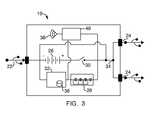
- FIG. 3illustrates a schematic view of the internal components of the charger unit of FIG. 1 .
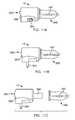
- FIG. 4shows a perspective view of an alternate embodiment of a portable charger unit in accordance with the present invention.
- FIG. 5shows a planar top view of the charger unit of FIG. 4 .
- FIGS. 6A and 6Bshow planar side views of the charger unit of FIG. 4 .
- FIGS. 7A and 7Bshow planar end views of the charger unit of FIG. 4 .
- FIG. 8shows a perspective view of another alternate embodiment of a portable charger unit in accordance with the present invention.
- FIGS. 9A and 9Bshow planar side views of the charger unit of FIG. 8 .
- FIG. 10shows a planar end view of the charger unit of FIG. 8 .
- FIGS. 11A , 11 B and 11 Cillustrate planar side views of a multi-source adapter unit comprising a part of a portable charger kit in accordance with the present invention.
- a portable charger kit in accordance with the present inventionis shown in FIG. 1 , and generally comprises a portable charger unit 10 having a rechargeable internal battery for recharging one or more electronic devices.
- the portable charger unit 10may have a variety of designs, as discussed further below, and may be provided with connector cables and adapters suitable for recharging the internal battery of the charger unit 10 and recharging the batteries of various electronic devices connected thereto.
- the portable charger kitmay be combined with at least one of a multi-source adapter unit 12 , as shown in FIGS. 11A-11C , for connecting the charger unit 10 to an external power source, and a squid connector 14 , for connecting one or more electronic devices to the charger unit 10 .
- Additional connector cablescan be provided with the kit, such as a USB connection cable 16 , for connecting the portable charger unit 10 to the adapter unit 12 or separately to a computer for recharging or data exchange, without departing from the principles and spirit of the present invention.
- a usercan recharge one or more electronic devices using the charger unit 10 , a computer, a wall socket, a car power outlet, or an airplane power outlet.
- the kit of the present inventioncan be used to charge smart phones, mobile phones, data tablets, music players, cameras, camcorders, gaming units, e-books, Bluetooth® headsets and earpieces, GPS devices, and the like, either individually or collectively in various combinations.
- the portable charger kitcan also be used as a conduit by which data can be exchanged between electronic devices and a portable computer or an external storage database.
- the charger unit 10comprises a charger housing 20 with a power input 22 ( FIG. 2A ) and at least one power output 24 ( FIG. 2B ).
- the power input 22generally takes the form of a mini-USB port, but can take the form of any known interface for connecting a device with a power source, including but not limited to a USB interface, a micro-USB interface, or an AC-to-DC connector interface.
- two USB portsare provided as power outputs 24 .
- the charger unit 10can be connected to two connector cords and/or devices via the USB ports at the same time.
- the power output ports 24can take the form of any known interface for connecting devices, including but not limited to a mini-USB interface, a micro-USB interface, or the like, and indeed, the two output ports 24 need not be the same type of interface. Additionally, the charger unit 10 can be connected to more than two devices at the same time using the squid connector 14 included in the portable charger kit of the present invention, as described in further detail below.
- the charger unit 10is readily portable as a result of the small size of the housing 20 .
- a lanyard 25can be provided for carrying the charger unit 10 .
- the power capacityis very high so that the charger 10 can accommodate multiple electronic devices at the same time.
- the charger unit 10comprises a rechargeable battery unit 26 disposed within the charger housing 20 that can be recharged by connecting the charger unit 10 to an external power source, such as a computer, a wall socket, a car or an airplane, using a power connector attached to the power input 22 of the charger unit 10 .
- the power connectorcan be a cable, such as the connection cable 16 having a mini-USB interface on one end for insertion into the input port 22 of the charger unit 10 and a standard USB interface on the other end for insertion into a USB port of a computer.
- the USB interface of the cable 16can be inserted into the adapter unit 12 included in the portable charger kit of the present invention, as discussed in further detail below, for connection to a standard power source, such as a wall-socket via a standard U.S. plug or a variety of foreign plug styles, a car charger socket—e.g., a cigarette lighter socket—via a car charger interface, or an airplane charger socket via an airplane charger interface.
- a standard power sourcesuch as a wall-socket via a standard U.S. plug or a variety of foreign plug styles
- a car charger sockete.g., a cigarette lighter socket
- the rechargeable battery unit 26is preferably a Lithium-Ion battery.
- the rechargeable battery unit 26is disposed within the charger housing 20 and is operatively connected with the power input port 22 for recharging the battery 26 when the charger unit 10 is connected to an external power source via the power input 22 .
- the rechargeable battery 26is also operatively connected with each of the power output ports 24 for recharging electronic devices connected to the charger unit 10 via the power output ports 24 from the rechargeable battery unit 26 .
- the charger housing 20also includes a power indicator means 28 that will indicate not only that an electrical current is being supplied to one or more electronic devices connected to the charger unit, but also what the remaining capacity of the internal battery 26 in the charger unit 10 is.
- the power indicator means 28comprises a series of four lights, but can include more or fewer lights without departing from the principles and spirit of the present invention.
- the power indicator means 28can comprise a digital interface that provides a battery capacity level for the internal rechargeable battery unit 26 , or another known means of providing battery level information.
- the charger housing 20may include additional indicator means providing separate information for separate functions of the charger unit.
- additional indicator meanscan be provided for the power level of the internal rechargeable battery unit 26 in the charger unit 10 and for the electronic devices attached to the charger unit 10 via each power output port 24 .
- the devicemay use a digital output that provides data regarding the power level of the internal rechargeable battery unit 26 separate from data regarding any electronic device attached to the charger unit 10 via each of the output ports 24 .
- the charger unit 10turns on when an electronic device needing charging is plugged into the charger unit 10 .
- the charger unit 10may include “shake-to-activate” technology, whereby the unit 10 is turned on by shaking the charger housing 20 .
- the charger unit 10can include an on/off button or switch for activating and deactivating the unit 10 , such as the on/off button 129 shown in FIG. 4 and on/off button 229 shown in FIG. 8 .
- the charger unit 10includes an internal switch 30 disposed within the charger housing 20 .
- the switch 30actuates to an “on” position when a device is connected to the charger unit 10 via an output port 24 .
- the switch 30actuates to an “on” position by a quick force—such as the force created by a shake of the charger 10 .
- the power indicator means 28can confirm that the switch has been turned “on” by lighting up.
- the switch 30is operatively connected to the rechargeable battery unit 26 .
- the charger housing 20encloses various electrical components (such as integrated circuit chips and other circuitry) to provide computing operations for the device.
- the integrated circuitry and other componentsmay comprise a power supply (e.g., the internal rechargeable battery), a microprocessor and controller (e.g., a CPU), memory (e.g., ROM, RAM, flash), a circuit board, a hard drive, and/or various input/output (I/O) support circuitry.
- the electrical componentsmay also include components for sending and receiving data and media (e.g., antenna, receiver, transmitter, transceiver, etc.).
- the charger unit 10comprises a controller, including a processing unit 32 , configured to execute instructions and to carry out operations associated with the charger unit 10 .
- the processing unit 32can keep track of the capacity level of the battery unit 26 , store data or provide a conduit means by which data can be exchanged between electronic devices, such as between a smart phone and a computer.
- the processing unit 32communicates with the battery unit 26 to determine how much capacity is remaining in the battery 26 .
- the processing unit 32communicates with the power indicator means 28 to provide the user with the appropriate signal for showing how much capacity is remaining in the internal rechargeable battery unit 26 —e.g., two out of four lights indicates a half-full battery.
- the power indicator means 28can activate to show the power level in the internal battery 26 using the “shake-to-activate” technology—i.e., information regarding the power level remaining in the battery unit 26 may be provided by shaking the charger unit 10 .
- indicator meanscan be provided to show the battery capacity level of one or more electronic devices connected to the charger unit 10 .
- the processing unit 32also includes a smart interface to determine the total current required for the specific devices connected to the charger unit 10 . For example, if two devices are connected to the charger unit 10 via each of the output ports 24 , the processing unit 32 will assess how much power is needed to fully charge each of the devices and efficiently allocate an appropriate current to each of the devices at a node 34 so that each device can be charged in the shortest amount of time without interfering with the charging operation of the other device or without overloading the capacity of the charger unit 10 . Similarly, if four devices are connected to the charger unit 10 via a squid connector 14 , the processing unit 32 will likewise assess how much power is needed to fully and efficiently charge each of the devices.
- the processing unit 32operates in connection with the input/output (I/O) support circuitry to control interactions with devices connected to the charger unit 10 .
- the I/O support circuitrymay be integrated with the processing unit 32 or may be a separate component.
- the I/O support circuitryoperates by exchanging power (and possibly data) between the charger unit 10 and electronic devices connected thereto via the output ports 24 .
- the processing unit 32also preferably includes a timer for automatically turning the charger unit 10 off if there is no device attached to the unit 10 for a predetermined period of time. In this regard, the capacity of the battery 26 can be preserved.
- the power indicator means 28Upon shut down of the charger unit 10 , the power indicator means 28 will indicate that the charger 10 is being turned off—for example, the lights will provide a sequential blinking signal.
- the processing unit 32further includes a storage unit 36 that provides a place to hold data or instructions for operation of the charger unit 10 and rechargeable battery unit 26 , or data exchanged between the charger unit 10 , a computer, and electronic devices connected to the charger unit 10 , or memory needed for further operations of the charger unit 10 .
- the charger unit 10can include communications components for sending and receiving data and media.
- an antenna 38is provided in connection with a transceiver 40 , or a receiver and transmitter (not shown), for communication over a wireless communication link.
- transceivers, receivers, and transmittersare generally well known in the technical field, and thus are not further discussed herein.
- the charger unit 10 of the present inventionis adaptable to recharge an electronic device connected to the charger unit 10 directly from the internal rechargeable battery unit 26 or alternately from a power source to which the charger unit 10 is connected.
- the charger unit 10can be a conduit through which a charge is provided from a standard power source, such as a wall socket, a car charger socket, an airplane charger socket, or even a computer. In this situation, the power charge bypasses the internal battery unit 26 .
- a charge provided from a standard power sourcecan recharge the internal battery unit 26 simultaneously with one or more electronic devices connected to the charger unit 10 .
- the portable charger unit 10can be disconnected from a standard power source, even when electronic devices are connected to the charger unit 10 , and continue to recharge the electronic device from the internal battery unit 26 without interfering with the recharging process. For example, the charge switches from the external power source to the internal battery unit 26 as necessary.
- the charger unit 110comprises a charger housing 120 having two connector cables 125 a and 125 b attached to the output ports of the charger unit 110 to connect respective electronic devices to the charger unit 110 to be recharged from an internal rechargeable battery unit 26 .
- the charger unit 110further includes a power indicator means 128 (comprising three lights) and an on-off button 129 , each operatively connected to the internal functional components and electrical circuitry for operating the charger unit 110 .
- the internal functional components and electrical circuitryincluding the internal rechargeable battery unit and a processing unit, operate similarly to the charger unit 10 shown in FIGS. 1-3 and discussed above.
- the connector cables 125 a and 125 bare permanently connected to the charger housing 120 and the output ports, although alternate embodiments may include connector cables that are removable and replaceable so as to permit different connection interfaces to be used with the charger unit 110 .
- Storage cavities 150 a and 150 bare formed into the charger housing 120 for receiving the connector cables 125 a and 125 b when not in use.
- FIGS. 4 , 6 A- 6 B and 7 Billustrate the connector cables 125 a and 125 b disposed within the exterior volume and footprint of the charger housing 120 in a non-use condition.
- FIG. 5shows the connector cables 125 a and 125 b removed from the storage cavities 150 a and 150 b to make the connection interfaces thereon exposed for connection to electronic devices.
- the connector cables 125 a and 125 beach include a distal end 156 having a connection interface 158 .
- one cable 125 acomprises a USB connection interface 158 a
- the other cable 125 bcomprises a micro-USB connection interface 158 b .
- the cables 125 a and 125 bmay utilize any known interface without departing from the spirit and principles of the present invention.
- the cables 125 a and 125 bcan be removable and replaceable so as to permit a user to easily change the connection interface for use with varying electronic devices.
- the proximal ends 160 of the connector cables 125 a and 125 binclude an interface that complements a respective output port provided in the charger housing 120 for attaching the connector cables 125 a and 125 b to the charger housing 120 .
- the connector cables 125 a and 125 bare preferably flexible so they can be bent away from the charger housing 120 to connect to an electronic device during use of the charger unit 110 .
- the storage cavities 150 a and 150 binclude channels 152 to receive a cord portion 162 of each of the cables 125 a and 125 b within the footprint of the charger housing 120 .
- the distal ends 156 of the connector cables 125 a and 125 beach includes a head 164 at the end of the respective cord portion 162 that is received within a respective storage cavity 150 a and 150 b on the charger housing 120 .
- the shape of the head 164complements the storage cavity to provide a sleek look to the charger housing 120 when the connector cables 125 a and 125 b are stored.
- the head 164 and cord portion 162 of each cable 125 a and 125 bis preferably snap-fitted into the storage cavity 150 a or 150 b when stored so that the connector cables 125 a and 125 b do not accidentally disengage or otherwise come loose from the storage cavities 150 a and 150 b.
- the charger housing 120further includes a power input port 122 for connecting the charger unit 110 to an external power source to recharge the internal rechargeable battery unit.
- the power input port 122comprises a USB port, but can take the form of any known interface for connecting a device with a power source, including but not limited to a mini-USB interface, a micro-USB interface, or an AC-to-DC connector interface.
- the charger housing 120can include one or more additional output ports comprising, for example, a USB port for receiving a separate connector cable (e.g., cable 16 ) to attach additional devices to the charger unit 110 .
- a squid connector 14can be used to connect multiple devices to the charger unit 110 even when both of the connector cables 125 a and 125 b are already connected to respective devices.
- one of the attached connector cables 125 a or 125 bmay be designated as a power input connection for recharging the internal rechargeable battery, and the other connector cable 125 a or 125 b and an output port (e.g., port 122 shown in FIG. 7A ) provided on the charger housing 110 can be used to charge multiple electronic devices simultaneously. In such a situation, the output port requires a separate cable to be connected between the charger unit 110 (via the output port) and the device(s) to be recharged.
- FIGS. 8-10Another alternate embodiment of the charger unit, generally designated by reference numeral 210 , is illustrated in FIGS. 8-10 .
- the charger unit 210comprises a charger housing 220 having three connector cables 225 a , 225 b and 225 c attached to output ports of the charger unit 210 to connect respective electronic devices to the charger unit 210 to be recharged from an internal rechargeable battery unit 26 .
- the charger unit 210further includes an on-off button 229 on the end that is operatively connected to the internal functional components and electrical circuitry for operating the charger unit 210 .
- the internal functional components and electrical circuitryincluding the internal rechargeable battery unit and a processing unit, operate similarly to the charger unit 10 shown in FIGS. 1-3 and discussed above.
- Storage cavities 250 a , 250 b and 250 care formed into the charger housing 220 for receiving the connector cables 225 a , 225 b and 225 c when not in use.
- FIGS. 9A and 9Btwo cavities 250 a and 250 b are formed on each side of the charger housing 220 for receiving a respective connector cable 225 a and 225 b .
- a third storage cavity 250 cis formed on the top of the charger housing 220 for receiving its own connector cable 225 c .
- FIGS. 9A and 9Billustrate connector cables 225 a and 225 b disposed within the volume of the charger housing 220 in a non-use condition. By comparison, FIG.
- connection interface 8shows one connector cable 225 c disposed in a non-use condition, with the other two connector cables 225 a and 225 b are removed from their storage cavities 250 a and 250 b to make the connection interfaces 258 thereon exposed for connection to electronic devices.
- the connector cables 225 a , 225 b and 225 care permanently connected to the charger housing 220 and their respective output ports, although alternate embodiments may include connector cables that are removable and replaceable so as to permit different connection interfaces to be used with the charger unit 210 .
- the connector cables 225 a , 225 b and 225 ceach include a distal end 256 having a connection interface 258 .
- one cable 225 acomprises a USB connection interface 258 a
- another cable 225 ccomprises a micro-USB connection interface 258 b
- a third cable 225 ccomprises an Apple® connection interface 258 c .
- the cables 225 a , 225 b and 225 cmay utilize any known interface without departing from the spirit and principles of the present invention.
- the cables 225 a , 225 b and 225 ccan be removable and replaceable so as to permit a user to easily change the connection interface for use with varying electronic devices.
- the proximal ends 260 of the connector cables 225 a , 225 b and 225 cinclude an interface that complements a respective output port provided in the charger housing 220 for attaching the connector cables 225 a , 225 b and 225 c to the charger housing 220 .
- the connector cables 225 a , 225 b and 225 care preferably flexible so that they can be bent away from the charger housing 220 to connect to an electronic device during use of the charger unit 210 .
- Each of the storage cavities 250 a , 250 b and 250 cincludes a channel 252 to receive a cord portion 262 of the cables 225 a , 225 b and 225 c within the footprint of the charger housing 220 .
- each connector cable 225 a , 225 b and 225 chaving the connection interface 258 a , 258 b or 258 c , includes a head 264 at the end of the cord portion 262 that is received within a respective storage cavity 250 a , 250 b or 250 c in the charger housing 220 .
- the shape of the head 264complements the storage cavity so that the cable and interface can be stored within the footprint and exterior volume of the charger housing 220 with no parts sticking out.
- each cable 225 a , 225 b and 225 cis preferably snap-fitted into a respective storage cavity 250 a , 250 b and 250 c when stored so that the connector cables 225 a , 225 b and 225 c do not accidentally disengage or otherwise come loose from the storage cavities 250 a , 250 b and 250 c.
- the charger housing 220further includes a power input port 222 for connecting the charger unit 210 to an external power source to recharge the internal rechargeable battery unit.
- the power input port 222comprises a USB port, but can take the form of any known interface for connecting a device with a power source, including but not limited to a mini-USB interface, a micro-USB interface, or an AC-to-DC connector interface.
- the charger housing 220can include one or more additional output ports comprising, for example, a USB port for receiving a separate connector cable to attach additional devices to the charger unit 210 .
- the squid connector 14can be used to connect multiple devices to the charger unit 210 even when all of the connector cables 225 a , 225 b and 225 c are already connected to respective devices.
- one of the attached connector cables 225 a , 225 b or 225 cmay be designated as a power input connection for recharging the internal rechargeable battery of the charger unit 210
- the other connector cables and at least one output port (e.g., port 222 ) provided on the charger housing 220can be used to charge multiple electronic devices simultaneously.
- the output portrequires a separate cable (e.g., cable 16 ) to be connected between the charger unit 210 (via the output port 222 ) and the device(s) to be recharged.
- the adapter unit 12comprises a multi-functional power supply adapter for providing power to a charger unit or a portable electronic device from multiple power sources, as needed.
- the adapter unit 12comprises a main body 300 having at least one interface for connecting a portable charger device (e.g., any one or more of the charger units 10 , 110 or 210 ) or another electronic device to a power source, such as a standard power outlet, a car charger port, an airplane charger port, or a computer, via the adapter unit 12 .
- the adapter unit 12provides an all-in-one charger adapter in a compact, lightweight unit.
- the adapter unit 12includes at least one output port 302 —e.g., a USB output port—whereby the adapter unit 12 can be connected to a charger unit or another electronic device via a separate cable (e.g., cable 16 ) to recharge the internal battery of the charger unit or other device.
- the output port 302permits the adapter unit 12 to be used to directly charge a computer or any other electronic device, for example, if the charger unit is not available or out of power.
- the adapter unit 12further includes a plug 304 for a standard wall socket, and at least one of a car charger interface 306 and an airplane charger interface 308 .
- the output port 302is electrically connected with each of the input interfaces 304 , 306 and 308 via conventional power conversion circuitry (not shown) for providing electrical power to a device connected to the output port 302 .
- the output port 302is electrically connected with the AC wall plug 304 via AC-DC power conversion circuitry, and with each of the DC charger interfaces 306 , 308 via DC-DC power conversion circuitry.
- the AC-DC power conversion circuitrymay be rated at 110-240V input, 5V/1 A output; the DC-DC power conversion circuitry may be rated at 12-24V input, 5V/1A output.
- the adapter unit 12also includes a power indicator 309 for confirming the existence of a power current moving between at least one of the input interfaces 304 , 306 or 308 and the output port 302 .
- the power indicator 309is a light that can indicate when a current is moving through the adapter unit 12 —i.e., the unit 12 is connected to an external power source via one of the input interfaces 304 , 306 and 308 and said power current can be supplied to a power charger or an electronic device when connected to the output port 302 of the adapter unit 12 .
- the power indicator 309is operatively connected with each of the input interfaces 304 , 306 and 308 , as well as the output port 302 , typically via the same circuitry interconnecting these elements for intended operation of the adapter unit 12 as described herein.
- the adapter unit 12may further include an internal rechargeable battery associated with the internal circuitry and electrical connections of the adapter unit 12 for supplying electrical current to the power output port 302 and for receiving electrical current from the input interfaces 304 , 306 and 308 .
- an internal rechargeable batteryassociated with the internal circuitry and electrical connections of the adapter unit 12 for supplying electrical current to the power output port 302 and for receiving electrical current from the input interfaces 304 , 306 and 308 .
- a battery unitis operatively connected with such inputs and outputs much in the same manner as for the portable charger devices described herein (e.g., any one or more of the charger units 10 , 110 or 210 ) and as illustrated in FIG. 3 .
- the battery unitmay be associated with an internal switch for controlling supply of an electrical current from the battery unit to the power output port 302 in response to an actuating motion of the adapter unit body—e.g., a shaking motion of the adapter unit 12 .
- the airplane charger interface 308is disposed within a removable car charger interface 306 , whereby the latter interface 306 can be removed to expose the former interface 308 for use.
- the plug interface 304is designed to fold within the footprint of the main body 300 for storage when not in use or needed, such as shown in FIG. 11A .
- the adapter unit 12can be designed with a compact, all-in-one design, which is advantageous for storage and travel.
- the car charger interface 306includes contacts 307 in accordance with standard car charger designs for providing a current from the power source through the adapter unit 14 .
- the car charger contacts 307are internally operatively connected with contacts on the airplane charger interface 308 so that the current is provided through the adapter unit 12 uninterrupted.
- the airplane contactsare exposed for connection to an airplane power socket.
- the adapter unit 12can be modified to use additional input connectors, such as foreign plug designs.
- the squid connector 14provides a user with the ability to connect multiple electronic devices to a power source for recharging.
- the squid connector 14comprises a USB interface on a first end 400 that is adapted to engage a complementary port on a power source, such as the power output ports of the portable charger units discussed above, the power output port on the adapter unit discussed above, or any other device with a USB port.
- the other end of the squid connector 14comprises multiple connector interfaces 402 adaptable for various electronic devices. As shown, the squid connector 14 provides connection capability of twelve different devices, but can be used with more or fewer connector interfaces 402 without departing from the principles and spirit of the present invention.
- the connector interfaces 402can be designed to attach to and accommodate various types of devices, including smart phones, mobile phones, data tablets, music players, cameras, camcorders, gaming units, e-books, Bluetooth® headsets and earpieces, GPS devices, and the like, from a variety of manufacturers and brands. In use, several electronic devices can be charged at the same time.
- the squid connector 14further includes a retractor 404 for extending the length of the cords of the squid connector 14 , and a power indicator 406 for confirming the existence of a power current being supplied to the electronic devices to be charged.
- the power connector 406is a light indicating that the charger or an external power source is supplying a power current to the devices through the squid connector 14 .
- each of the components shown in FIG. 1i.e., the charger unit 10 , 110 or 210 , the adapter unit 12 , and the squid connector 14 —can be used individually, or in various combinations, as needed.
- a charger unitcan be directly connected with an electronic device via one of its USB output ports.
- the charger unit alonecan be used to charge two electronic devices because it has two such output ports.
- the charger unitcan be connected to more than two devices at the same time using the squid connector, as connected to one of the USB output ports on the charger unit.
- the charger unitcan be combined with the adapter unit to recharge the battery in the charger unit.
Landscapes
- Engineering & Computer Science (AREA)
- Power Engineering (AREA)
- Charge And Discharge Circuits For Batteries Or The Like (AREA)
Abstract
Description
Claims (14)
Priority Applications (1)
| Application Number | Priority Date | Filing Date | Title |
|---|---|---|---|
| US13/801,338US9093848B2 (en) | 2011-08-10 | 2013-03-13 | Multi-source power adapter |
Applications Claiming Priority (3)
| Application Number | Priority Date | Filing Date | Title |
|---|---|---|---|
| US201161521815P | 2011-08-10 | 2011-08-10 | |
| US13/571,992US20130043827A1 (en) | 2011-08-10 | 2012-08-10 | Portable power charger |
| US13/801,338US9093848B2 (en) | 2011-08-10 | 2013-03-13 | Multi-source power adapter |
Related Parent Applications (1)
| Application Number | Title | Priority Date | Filing Date |
|---|---|---|---|
| US13/571,992ContinuationUS20130043827A1 (en) | 2011-08-10 | 2012-08-10 | Portable power charger |
Publications (2)
| Publication Number | Publication Date |
|---|---|
| US20140042969A1 US20140042969A1 (en) | 2014-02-13 |
| US9093848B2true US9093848B2 (en) | 2015-07-28 |
Family
ID=50068635
Family Applications (2)
| Application Number | Title | Priority Date | Filing Date |
|---|---|---|---|
| US13/571,992AbandonedUS20130043827A1 (en) | 2011-08-10 | 2012-08-10 | Portable power charger |
| US13/801,338Active2032-12-19US9093848B2 (en) | 2011-08-10 | 2013-03-13 | Multi-source power adapter |
Family Applications Before (1)
| Application Number | Title | Priority Date | Filing Date |
|---|---|---|---|
| US13/571,992AbandonedUS20130043827A1 (en) | 2011-08-10 | 2012-08-10 | Portable power charger |
Country Status (2)
| Country | Link |
|---|---|
| US (2) | US20130043827A1 (en) |
| WO (1) | WO2014026181A1 (en) |
Cited By (14)
| Publication number | Priority date | Publication date | Assignee | Title |
|---|---|---|---|---|
| US20150015180A1 (en)* | 2013-03-20 | 2015-01-15 | Garold C. Miller | Portable Power Charger with Wireless and Direct Charging Connectivity |
| US20160209885A1 (en)* | 2013-10-04 | 2016-07-21 | Aquaterra Limited | Power adapter unit with integrated input/output interface, and portable electronic device with storage recess for multifunction power adapter |
| US9667092B2 (en) | 2013-03-20 | 2017-05-30 | Halo International SEZC Ltd. | Power charging kit with wireless and direct charging connectivity |
| US20180102655A1 (en)* | 2016-10-11 | 2018-04-12 | Halo2Cloud, LLC | Decorative and portable power charger with motion light |
| US20180102654A1 (en)* | 2016-10-11 | 2018-04-12 | Halo2Cloud, LLC | Decorative and portable power charger with motion light |
| US10033294B2 (en)* | 2014-11-13 | 2018-07-24 | Ricot Riphin | Folding plug with safety cover |
| US20180254642A1 (en)* | 2017-03-01 | 2018-09-06 | Roy Corrie | Multi-Device Charging Assembl |
| US20180269640A1 (en)* | 2016-10-31 | 2018-09-20 | Leroy Walker | Universal multi-charger device |
| US10116153B2 (en)* | 2016-08-24 | 2018-10-30 | Tianjin Synergy Groups Co., Ltd. | Mobile power supply capable of charging itself and electronic device |
| USD848411S1 (en) | 2017-10-24 | 2019-05-14 | Darryl Deshon JONES, JR. | Charging case for an electronic device |
| US10922408B2 (en) | 2013-03-20 | 2021-02-16 | Halo International SEZC Ltd. | Portable power charger with wireless and direct charging connectivity |
| US11374412B2 (en) | 2017-04-14 | 2022-06-28 | Parker House Mfg. Co., Inc. | Furniture power management system |
| US11552485B2 (en) | 2019-01-08 | 2023-01-10 | Bollinger Industries, Inc. | Fold-flat car charger interface |
| US11705683B2 (en) | 2020-04-22 | 2023-07-18 | Black & Decker Inc. | Battery pack power transfer adaptor |
Families Citing this family (143)
| Publication number | Priority date | Publication date | Assignee | Title |
|---|---|---|---|---|
| US20160211682A1 (en)* | 2009-11-19 | 2016-07-21 | Tseng-Lu Chien | Plug-In AC Outlet Electric Device Has Replaceable Rechargeable Battery |
| TW201331756A (en)* | 2012-01-18 | 2013-08-01 | Guangdong Jetfast Portable Lighting Co Ltd | Universal serial bus (USB) charging controller |
| USD720687S1 (en) | 2012-05-24 | 2015-01-06 | Mophie, Inc. | Mobile battery charger |
| USD728467S1 (en) | 2012-05-24 | 2015-05-05 | Mophie, Inc. | Mobile battery charger |
| USD697867S1 (en)* | 2012-08-10 | 2014-01-21 | Halo2Cloud Llc | Portable power charger |
| US9466998B2 (en)* | 2012-08-22 | 2016-10-11 | David Wyskiel | Emergency charging and fast charging for mobile electronic devices |
| US9487100B2 (en)* | 2012-09-14 | 2016-11-08 | General Electric Company | Electrical vehicle charging device having a brake to prevent extension and retraction of the power conduit |
| USD727843S1 (en)* | 2012-12-21 | 2015-04-28 | Halo2Cloud, LLC | Portable power charger |
| USD727844S1 (en)* | 2012-12-21 | 2015-04-28 | Halo2Cloud, LLC | Portable power charger |
| USD742823S1 (en)* | 2013-03-27 | 2015-11-10 | Nitz Engineering Gmbh | Charger |
| USD736705S1 (en)* | 2013-05-08 | 2015-08-18 | Hugh Brogan | Battery pack |
| WO2014205625A1 (en)* | 2013-06-24 | 2014-12-31 | 吉瑞高新科技股份有限公司 | Usb charger capable of displaying electric quantity of battery rod, and electric quantity display method thereof |
| USD743883S1 (en)* | 2013-07-09 | 2015-11-24 | Shenzhen Lepow Creative Technology Co., Ltd. | Portable charger |
| US20150091380A1 (en)* | 2013-09-27 | 2015-04-02 | Kuang Ying Computer Equipment Co., Ltd. | Power conversion device with multiple interfaces |
| JP2016226066A (en)* | 2013-10-30 | 2016-12-28 | 三洋電機株式会社 | Portable power supply device |
| USD713785S1 (en)* | 2013-11-19 | 2014-09-23 | Tego LLP | Power card |
| WO2015081125A1 (en) | 2013-11-27 | 2015-06-04 | Mophie, Inc. | Battery pack with supplemental memory |
| US9509153B2 (en) | 2013-12-09 | 2016-11-29 | Kenneth E. Clark | Portable multiple mobile electronic device charging station |
| US9402453B2 (en)* | 2013-12-09 | 2016-08-02 | Kanex | Mobile device transmission apparatus with integrated tool |
| USD733043S1 (en) | 2013-12-09 | 2015-06-30 | Mophie, Inc. | Battery pack |
| US10243377B2 (en)* | 2013-12-09 | 2019-03-26 | Kenneth E. Clark | Portable multiple mobile electronic device charging station |
| USD721646S1 (en)* | 2014-01-02 | 2015-01-27 | Mophie, Inc. | Battery pack with integrated connector |
| USD722961S1 (en)* | 2014-01-14 | 2015-02-24 | Gadmei Electronics Technology Co., Ltd. | Portable power source |
| US11462649B2 (en) | 2014-10-16 | 2022-10-04 | Lat Enterprises, Inc. | Portable power case |
| US10531590B2 (en) | 2014-10-16 | 2020-01-07 | Lat Enterprises, Inc. | System for supplying power to at least one power distribution and data hub using a portable battery pack |
| US10727457B2 (en) | 2014-01-15 | 2020-07-28 | Lat Enterprises, Inc. | System for supplying power to a portable battery using at least one solar panel |
| US11025075B2 (en) | 2014-10-16 | 2021-06-01 | Lat Enterprises, Inc. | Portable power case with heat-resistant material |
| US12368409B1 (en) | 2014-01-15 | 2025-07-22 | Lat Enterprises, Inc. | Foldable solar panel |
| US10991992B2 (en) | 2014-01-15 | 2021-04-27 | Lat Enterprises, Inc. | System for supplying power to a portable battery using at least one solar panel |
| US11996803B2 (en) | 2014-01-15 | 2024-05-28 | Lat Enterprises, Inc. | Foldable solar panel |
| US11304500B2 (en) | 2014-01-15 | 2022-04-19 | Lat Enterprises, Inc. | Wearable and replaceable pouch or skin for holding a portable battery pack |
| US12119785B2 (en) | 2014-01-15 | 2024-10-15 | Lat Enterprises, Inc. | Dual voltage solar panel |
| US11302987B2 (en) | 2014-10-16 | 2022-04-12 | Lat Enterprises | Material for dissipating heat from and/or reducing heat signature of electronic devices and clothing |
| US11876354B2 (en) | 2014-01-15 | 2024-01-16 | Lat Enterprises, Inc. | Wearable and replaceable pouch or skin for holding a portable battery pack |
| US10944140B2 (en)* | 2014-01-15 | 2021-03-09 | Lat Enterprises, Inc. | Wearable and replaceable pouch or skin for holding a portable battery pack |
| US9235044B2 (en) | 2014-01-29 | 2016-01-12 | The Gillette Company | Light activated power indicator |
| USD711822S1 (en)* | 2014-01-31 | 2014-08-26 | Bernard Emano | Portable rechargeable device charger |
| US9595840B2 (en) | 2014-03-10 | 2017-03-14 | Halo International SEZC Ltd. | Lightweight, wallet-sized portable power charger kit with removable charging cable |
| US20150295440A1 (en)* | 2014-04-15 | 2015-10-15 | C-Tech United Corp. | Mobile power supply device |
| US9153986B1 (en) | 2014-04-15 | 2015-10-06 | Fuelbox, Inc. | Versatile plug and play charging station |
| USD745456S1 (en)* | 2014-04-29 | 2015-12-15 | Linear Flux Company Limited | Electrical charger |
| US9800075B2 (en) | 2014-06-04 | 2017-10-24 | Societe Bic | Smart charging cable and method for operating a portable electronic device |
| JP2017527923A (en)* | 2014-06-04 | 2017-09-21 | ネクセパック リミテッドNexpack Limited | Battery powered platform for interchangeable modules |
| US20150366093A1 (en)* | 2014-06-16 | 2015-12-17 | Bbd Technologies, Llc | Case For Portable Electronic Device With Integral Detachable Power Converter And USB Connector |
| KR101472537B1 (en)* | 2014-06-20 | 2014-12-16 | (주) 제이앤케이사이언스 | Rechargeable battery with Universal Serial Bus connecter |
| US9564766B2 (en)* | 2014-07-30 | 2017-02-07 | Elwha Llc | Controllable energy transfer between portable devices |
| US10033204B2 (en) | 2014-09-03 | 2018-07-24 | Mophie, Inc. | Systems and methods for battery charging and management |
| US20160087470A1 (en)* | 2014-09-18 | 2016-03-24 | Christian M Lizama | Wearable Mobile Phone Charging Apparatus |
| CA2962554A1 (en)* | 2014-09-26 | 2016-03-31 | Brightcharger Europe Oy Ltd | Disconnecting supply of electric charging current |
| US9153985B1 (en) | 2014-09-30 | 2015-10-06 | Mophie, Inc. | Portable charging device |
| USD742311S1 (en)* | 2014-10-02 | 2015-11-03 | Halo2Cloud Llc. | Portable power charger |
| USD751816S1 (en) | 2014-10-02 | 2016-03-22 | Halo2Cloud, LLC | Combined wallet and portable power charger |
| KR20160041439A (en)* | 2014-10-07 | 2016-04-18 | 삼성전자주식회사 | Electronic device for chagring and method for controlling power in electronic device for chagring |
| US11025076B2 (en) | 2014-10-16 | 2021-06-01 | Lat Enterprises, Inc. | Portable power case with lithium iron phosphate battery |
| US10616534B2 (en) | 2014-10-16 | 2020-04-07 | Lat Enterprises, Inc. | Personal tactical system and network |
| US12407175B2 (en) | 2014-10-16 | 2025-09-02 | Lat Enterprises, Inc. | Wearable and lightweight portable power case |
| US10063958B2 (en) | 2014-11-07 | 2018-08-28 | Microsoft Technology Licensing, Llc | Earpiece attachment devices |
| USD783525S1 (en)* | 2015-01-05 | 2017-04-11 | Sumeet Kumar Gupta | Combination battery, charger and cables for electronic equipment |
| USD742312S1 (en)* | 2015-01-05 | 2015-11-03 | Sumeet Kumar Gupta | Combination battery, charger and cables for electronic equipment |
| USD760645S1 (en)* | 2015-01-15 | 2016-07-05 | Dongguan Large Electronics Co., Ltd. | Power bank |
| US10230252B2 (en)* | 2015-01-30 | 2019-03-12 | Symbol Technologies, Llc | Method and system for charging a battery based on an identifier of a power cable |
| US20160233662A1 (en) | 2015-02-06 | 2016-08-11 | Mathew Inskeep | Jump Starter Auto Safety Jumper Module |
| US11075529B2 (en)* | 2015-02-06 | 2021-07-27 | Halo International SEZC Ltd. | Decorative portable power charger |
| US9696782B2 (en) | 2015-02-09 | 2017-07-04 | Microsoft Technology Licensing, Llc | Battery parameter-based power management for suppressing power spikes |
| US10158148B2 (en) | 2015-02-18 | 2018-12-18 | Microsoft Technology Licensing, Llc | Dynamically changing internal state of a battery |
| USD773389S1 (en)* | 2015-02-23 | 2016-12-06 | Black & Decker Inc. | Battery pack |
| USD764404S1 (en)* | 2015-02-25 | 2016-08-23 | Sun Pleasure Co. Limited | Portable battery |
| US9748765B2 (en) | 2015-02-26 | 2017-08-29 | Microsoft Technology Licensing, Llc | Load allocation for multi-battery devices |
| US20160275400A1 (en)* | 2015-03-19 | 2016-09-22 | Microsoft Technology Licensing, Llc | Device Charging Discovery Service |
| USD801269S1 (en)* | 2015-03-27 | 2017-10-31 | Design Co., Ltd. | Battery |
| USD766821S1 (en) | 2015-04-02 | 2016-09-20 | Linear Flux Company Limited | Electrical charger |
| WO2016182474A1 (en)* | 2015-05-14 | 2016-11-17 | Марина Георгиевна КЛОЧКО | Charging device |
| US20160344213A1 (en)* | 2015-05-18 | 2016-11-24 | Godfrey Chukuma Iwu | Battery phone charger able to charge phones or tablets while walking on the road |
| US9455528B1 (en) | 2015-06-01 | 2016-09-27 | TwinTech Industry, Inc. | Multi-plug USB connector with swappable tip |
| US9270038B1 (en)* | 2015-06-01 | 2016-02-23 | TwinTech Industry, Inc. | Multi-plug USB connector with swappable tip |
| USD741258S1 (en)* | 2015-06-01 | 2015-10-20 | TwinTech Industry, Inc. | Charging device with multiple connections |
| US9787128B2 (en)* | 2015-07-21 | 2017-10-10 | Hon Hai Precision Industry Co., Ltd. | Wireless charger and wireless charging method |
| US9673645B1 (en)* | 2015-07-21 | 2017-06-06 | Bruce Emerick | Charging and powering device |
| US9736531B2 (en) | 2015-09-08 | 2017-08-15 | Google Inc. | Video media streaming device |
| US10277275B2 (en)* | 2015-09-08 | 2019-04-30 | Google Llc | Audio media streaming device |
| US20170093204A1 (en)* | 2015-09-26 | 2017-03-30 | Sherry Knowles | Portable Flexible Solar Powered Recharging Device |
| US20170194806A1 (en)* | 2015-10-08 | 2017-07-06 | Mathew Inskeep | Portable Power Station Unit With Two Way Universal Serial BUS |
| USD823239S1 (en)* | 2015-10-29 | 2018-07-17 | Sumeet Kumar Gupta | Combination battery, charger and cables for electronic equipment |
| US9939862B2 (en) | 2015-11-13 | 2018-04-10 | Microsoft Technology Licensing, Llc | Latency-based energy storage device selection |
| US10061366B2 (en) | 2015-11-17 | 2018-08-28 | Microsoft Technology Licensing, Llc | Schedule-based energy storage device selection |
| US20170163063A1 (en)* | 2015-12-02 | 2017-06-08 | Yong-Yue Cai | Portable phone charger with auxiliary functions |
| US9793570B2 (en) | 2015-12-04 | 2017-10-17 | Microsoft Technology Licensing, Llc | Shared electrode battery |
| US20170224028A1 (en)* | 2016-02-05 | 2017-08-10 | Myoung-Il KIM | Portable charging apparatus and pants that allow charging using the same |
| US20170264118A1 (en)* | 2016-03-11 | 2017-09-14 | Halo2Cloud Llc | Combination portable power charger and compact mirror |
| US10283975B1 (en)* | 2016-03-28 | 2019-05-07 | Amazon Technologies, Inc. | Smart diagnostics for hot-pluggable battery systems |
| USD815593S1 (en) | 2016-04-21 | 2018-04-17 | Scosche Industries, Inc. | Battery pack with magnetic attachment |
| USD823279S1 (en)* | 2016-04-21 | 2018-07-17 | Shenzhen Voxtech Co., Ltd. | Bone conduction speaker |
| US10180251B2 (en)* | 2016-07-21 | 2019-01-15 | Michael Duque | Power stand with switchable power and changeable utility models |
| USD841575S1 (en)* | 2016-11-11 | 2019-02-26 | Incipio, Llc | Charging accessory |
| DE102016222975A1 (en)* | 2016-11-18 | 2018-05-24 | Robert Bosch Gmbh | distribution unit |
| US10505392B2 (en) | 2016-12-01 | 2019-12-10 | Scosche Industries, Inc. | Magnetic device mount |
| JP2018106908A (en)* | 2016-12-26 | 2018-07-05 | 有限会社菊榮商事 | battery pack |
| CN106532868A (en)* | 2016-12-30 | 2017-03-22 | 特顶通讯科技有限公司 | Convenient-to-carry mobile phone-integrated power bank |
| USD840332S1 (en)* | 2017-01-09 | 2019-02-12 | Shenzhen Jingyuecheng Technology Co., Ltd | Power bank |
| TWI626813B (en)* | 2017-01-26 | 2018-06-11 | 東莞崧騰電子有限公司 | Electronic device charger |
| US10389154B2 (en)* | 2017-06-23 | 2019-08-20 | Dell Products L.P. | Power storage adapter using a high efficiency charging method |
| US10928880B2 (en) | 2017-06-23 | 2021-02-23 | Dell Products L.P. | Power storage adapter for communicating battery data with a portable information handling system |
| US10978896B2 (en) | 2017-06-23 | 2021-04-13 | Dell Products L.P. | High efficiency power storage adapter |
| US10381844B2 (en)* | 2017-06-23 | 2019-08-13 | Dell Products L.P. | Sourcing power from a battery or AC-DC converter of a power storage adapter |
| US10452102B2 (en) | 2017-06-23 | 2019-10-22 | Dell Products L.P. | Power delivery contract establishment in a power storage adapter |
| US10476288B2 (en) | 2017-06-23 | 2019-11-12 | Dell Products L.P. | Power storage adapter for peak shift operation with a portable information handling system |
| CN207304039U (en)* | 2017-07-07 | 2018-05-01 | 深圳市正浩创新科技有限公司 | Mobile power |
| US10608443B2 (en) | 2017-08-15 | 2020-03-31 | Dell Products L.P. | Battery management using battery temperature distribution |
| CN207304056U (en)* | 2017-08-18 | 2018-05-01 | 深圳市正浩创新科技有限公司 | Mobile power |
| US10642333B2 (en) | 2017-08-24 | 2020-05-05 | Dell Products L.P. | Power storage adapter for efficient supply of power of multiple portable information handling systems |
| US10673271B2 (en) | 2017-09-01 | 2020-06-02 | Dell Products L.P. | Efficient charging of multiple portable information handling systems based on learned charging characteristics |
| US10620679B2 (en) | 2017-09-01 | 2020-04-14 | Dell Products L.P. | Prioritizing supplying electrical power by a power storage adapter to connected devices |
| US10404105B2 (en) | 2017-09-14 | 2019-09-03 | Dell Products L.P. | Power storage adapter for wireless power transmission |
| US10714797B2 (en) | 2017-09-18 | 2020-07-14 | Dell Products L.P. | Multilayer thermal laminate with aerogel for battery cell enclosures |
| US11513928B2 (en) | 2017-09-18 | 2022-11-29 | Dell Products L.P. | Power storage adapter with power cable validation |
| US10488906B2 (en) | 2017-09-26 | 2019-11-26 | Dell Products L.P. | Power delivery based on temperature and other factors in a power storage adapter |
| USD870093S1 (en) | 2017-10-25 | 2019-12-17 | Scosche Industries, Inc. | Desk attachment for magnetic device mount |
| USD915296S1 (en)* | 2018-07-12 | 2021-04-06 | Design Pool Limited | Charging cable |
| US10778020B1 (en) | 2018-12-04 | 2020-09-15 | Michael K. Torem | Multiport portable power bank |
| USD887349S1 (en) | 2018-12-27 | 2020-06-16 | Scosche Industries, Inc. | Modular smartphone inductive charging station |
| USD887350S1 (en) | 2018-12-27 | 2020-06-16 | Scosche Industries, Inc. | Modular tablet charging station |
| US11509149B2 (en) | 2018-12-27 | 2022-11-22 | Scosche Industries, Inc. | Modular device charging station |
| USD886735S1 (en) | 2018-12-27 | 2020-06-09 | Scosche Inudstries, Inc. | Modular watch charging station |
| US11011921B2 (en) | 2018-12-31 | 2021-05-18 | Scosche Industries, Inc. | Inductive charger with rotatable magnetic mount |
| USD890158S1 (en) | 2019-01-02 | 2020-07-14 | Scosche Industries, Inc. | Rotatable head magnetic device mount |
| USD890739S1 (en) | 2019-01-04 | 2020-07-21 | Scosche Industries, Inc. | Suction cup mount with multi-part stalk |
| USD890159S1 (en) | 2019-01-04 | 2020-07-14 | Scosche Industries, Inc. | Suction cup mount base |
| USD896734S1 (en) | 2019-01-04 | 2020-09-22 | Scosche Industries, Inc. | Adhesive mount base |
| USD940647S1 (en) | 2019-01-07 | 2022-01-11 | Mophie Inc. | Battery pack |
| CN110176792B (en)* | 2019-03-22 | 2020-07-07 | 珠海智融科技有限公司 | Multi-port quick-charging mobile power supply circuit and control method thereof |
| CN109995064B (en)* | 2019-04-12 | 2024-05-24 | 湖南富能宝储能科技有限公司 | Mobile energy storage cluster power supply system |
| DE102019118712A1 (en)* | 2019-07-10 | 2021-01-14 | Endress+Hauser Conducta Gmbh+Co. Kg | Field device and remote station |
| USD939438S1 (en)* | 2019-09-02 | 2021-12-28 | Luxshare Precision Industry Co., Ltd. | Charger |
| EP3822110A1 (en)* | 2019-11-15 | 2021-05-19 | EVBox Intelligence B.V. | Charge cable management system |
| CN112087152A (en)* | 2020-09-11 | 2020-12-15 | 深圳市东峰盛科技有限公司 | Multi-interface power adapter circuit |
| USD1038924S1 (en) | 2021-12-08 | 2024-08-13 | Scosche Industries, Inc. | Magnetic device mount |
| USD1006010S1 (en) | 2021-12-30 | 2023-11-28 | Scosche Industries, Inc. | Magnetic device mounting head |
| USD1061500S1 (en) | 2022-01-04 | 2025-02-11 | Scosche Industries, Inc. | Charging cradle |
| US11520393B1 (en)* | 2022-01-17 | 2022-12-06 | Shenzhen Tianyu Electronic Commerce Co., Ltd. | Device for improving charging transmission power for external equipment based on USB port of computer |
| US20240030729A1 (en)* | 2022-07-25 | 2024-01-25 | Alice Chen Knowles | USB conversion charging device |
| US20240268042A1 (en)* | 2023-02-08 | 2024-08-08 | Assurant, Inc. | Container for electronic devices |
| USD1080535S1 (en) | 2023-04-13 | 2025-06-24 | Scosche Industries, Inc. | Modular tablet charging station |
| USD1073440S1 (en) | 2023-06-09 | 2025-05-06 | Scosche Industries, Inc. | Container magnetic device mount |
Citations (26)
| Publication number | Priority date | Publication date | Assignee | Title |
|---|---|---|---|---|
| US5829993A (en) | 1996-12-16 | 1998-11-03 | Formosa Electronic Industries Inc. | Charger with a replaceable electrical plug |
| USD416233S (en) | 1998-09-11 | 1999-11-09 | Hon Hai Precision Ind. Co., Ltd. | Cable connector assembly |
| US6116960A (en) | 1998-08-02 | 2000-09-12 | Motorola, Inc. | Cigarette lighter adapter |
| US6358096B1 (en) | 2000-12-29 | 2002-03-19 | Gateway, Inc. | Multiple source power adapter for output power control |
| US6528970B1 (en)* | 2001-11-29 | 2003-03-04 | Primax Electronics Ltd. | Charger capable of converting multiple power sources |
| US6551142B2 (en) | 2001-02-28 | 2003-04-22 | United Global Sourcing Incorporated | Vehicle cigarette lighter connector |
| US6612875B1 (en) | 2002-07-05 | 2003-09-02 | Sheng Hsin Liao | Multifunctional vehicle adapter |
| US20040085694A1 (en) | 2002-11-01 | 2004-05-06 | Germagian Mark H. | Universal multiple device power adapter and carry case |
| US6894457B2 (en)* | 2002-11-01 | 2005-05-17 | American Power Conversion Corporation | Universal multiple device power adapter and carry case |
| US7011538B2 (en)* | 2004-06-02 | 2006-03-14 | Elementech International Co., Ltd. | Dual input charger with cable storing mechanism |
| US7030517B2 (en) | 2001-01-31 | 2006-04-18 | International Business Machines Corporation | Mobile devices power server |
| USD554585S1 (en) | 2007-01-23 | 2007-11-06 | David Nazar | Three-in-one adapter |
| USD563873S1 (en) | 2006-11-27 | 2008-03-11 | Cheng Uei Precision Industry Co., Ltd. | Car charger |
| USD574833S1 (en) | 2006-08-07 | 2008-08-12 | I-Tec Electronics, Inc. | Multi-source power adapter for USB port |
| USD585825S1 (en)* | 2008-04-18 | 2009-02-03 | Ronald Ji | Car charger |
| JP2009065769A (en) | 2007-09-05 | 2009-03-26 | Jet Neko Kk | Cord connector for charging portable telephone |
| USD594817S1 (en) | 2008-06-16 | 2009-06-23 | Usa Wireless Solutions | Universal charger |
| JP2010104155A (en) | 2008-10-23 | 2010-05-06 | Strapya Next:Kk | Charger for portable electronic apparatus |
| USD633436S1 (en) | 2009-05-14 | 2011-03-01 | Griffin Technology, Inc. | Charger with backup battery |
| USD636337S1 (en) | 2010-02-26 | 2011-04-19 | Research In Motion Limited | Cable connector |
| US8109792B2 (en)* | 2006-09-06 | 2012-02-07 | Analog Devices, Inc. | System with cable mode converter |
| USD656899S1 (en) | 2010-09-24 | 2012-04-03 | Brad Webb | Mobile vehicle dual power adapter |
| US20120187902A1 (en) | 2011-01-06 | 2012-07-26 | Wen Fee Wang | Portable battery charger |
| US20120238132A1 (en) | 2010-03-12 | 2012-09-20 | Mcsweyn Christopher | Portable universal serial bus (usb) cable keychain assembly with carabiner clip |
| US8547056B2 (en)* | 2011-01-06 | 2013-10-01 | Ching-Chih Chang | One-piece car charger |
| US20140152257A1 (en)* | 2012-12-03 | 2014-06-05 | Garold C. Miller | Compact portable battery charger |
Family Cites Families (6)
| Publication number | Priority date | Publication date | Assignee | Title |
|---|---|---|---|---|
| JP4753817B2 (en)* | 2006-09-05 | 2011-08-24 | 三洋電機株式会社 | Charger |
| US8368346B2 (en)* | 2007-03-26 | 2013-02-05 | The Gillette Company | Portable energy storage and charging device |
| TWM329280U (en)* | 2007-09-26 | 2008-03-21 | Formosa Electronic Ind Inc | Portable power supply module with wire-coiling structure |
| US20090267562A1 (en)* | 2008-04-23 | 2009-10-29 | Callpod Inc. | Portable battery charger for multiple electronic devices |
| USD628535S1 (en)* | 2010-06-24 | 2010-12-07 | Cheng Uei Precision Industry Co., Ltd. | Portable charger |
| US20120268064A1 (en)* | 2011-04-19 | 2012-10-25 | Powermat Usa, Llc | Inductively Rechargeable Portable Charger |
- 2012
- 2012-08-10USUS13/571,992patent/US20130043827A1/ennot_activeAbandoned
- 2013
- 2013-03-13USUS13/801,338patent/US9093848B2/enactiveActive
- 2013-08-12WOPCT/US2013/054498patent/WO2014026181A1/enactiveApplication Filing
Patent Citations (26)
| Publication number | Priority date | Publication date | Assignee | Title |
|---|---|---|---|---|
| US5829993A (en) | 1996-12-16 | 1998-11-03 | Formosa Electronic Industries Inc. | Charger with a replaceable electrical plug |
| US6116960A (en) | 1998-08-02 | 2000-09-12 | Motorola, Inc. | Cigarette lighter adapter |
| USD416233S (en) | 1998-09-11 | 1999-11-09 | Hon Hai Precision Ind. Co., Ltd. | Cable connector assembly |
| US6358096B1 (en) | 2000-12-29 | 2002-03-19 | Gateway, Inc. | Multiple source power adapter for output power control |
| US7030517B2 (en) | 2001-01-31 | 2006-04-18 | International Business Machines Corporation | Mobile devices power server |
| US6551142B2 (en) | 2001-02-28 | 2003-04-22 | United Global Sourcing Incorporated | Vehicle cigarette lighter connector |
| US6528970B1 (en)* | 2001-11-29 | 2003-03-04 | Primax Electronics Ltd. | Charger capable of converting multiple power sources |
| US6612875B1 (en) | 2002-07-05 | 2003-09-02 | Sheng Hsin Liao | Multifunctional vehicle adapter |
| US6894457B2 (en)* | 2002-11-01 | 2005-05-17 | American Power Conversion Corporation | Universal multiple device power adapter and carry case |
| US20040085694A1 (en) | 2002-11-01 | 2004-05-06 | Germagian Mark H. | Universal multiple device power adapter and carry case |
| US7011538B2 (en)* | 2004-06-02 | 2006-03-14 | Elementech International Co., Ltd. | Dual input charger with cable storing mechanism |
| USD574833S1 (en) | 2006-08-07 | 2008-08-12 | I-Tec Electronics, Inc. | Multi-source power adapter for USB port |
| US8109792B2 (en)* | 2006-09-06 | 2012-02-07 | Analog Devices, Inc. | System with cable mode converter |
| USD563873S1 (en) | 2006-11-27 | 2008-03-11 | Cheng Uei Precision Industry Co., Ltd. | Car charger |
| USD554585S1 (en) | 2007-01-23 | 2007-11-06 | David Nazar | Three-in-one adapter |
| JP2009065769A (en) | 2007-09-05 | 2009-03-26 | Jet Neko Kk | Cord connector for charging portable telephone |
| USD585825S1 (en)* | 2008-04-18 | 2009-02-03 | Ronald Ji | Car charger |
| USD594817S1 (en) | 2008-06-16 | 2009-06-23 | Usa Wireless Solutions | Universal charger |
| JP2010104155A (en) | 2008-10-23 | 2010-05-06 | Strapya Next:Kk | Charger for portable electronic apparatus |
| USD633436S1 (en) | 2009-05-14 | 2011-03-01 | Griffin Technology, Inc. | Charger with backup battery |
| USD636337S1 (en) | 2010-02-26 | 2011-04-19 | Research In Motion Limited | Cable connector |
| US20120238132A1 (en) | 2010-03-12 | 2012-09-20 | Mcsweyn Christopher | Portable universal serial bus (usb) cable keychain assembly with carabiner clip |
| USD656899S1 (en) | 2010-09-24 | 2012-04-03 | Brad Webb | Mobile vehicle dual power adapter |
| US20120187902A1 (en) | 2011-01-06 | 2012-07-26 | Wen Fee Wang | Portable battery charger |
| US8547056B2 (en)* | 2011-01-06 | 2013-10-01 | Ching-Chih Chang | One-piece car charger |
| US20140152257A1 (en)* | 2012-12-03 | 2014-06-05 | Garold C. Miller | Compact portable battery charger |
Non-Patent Citations (1)
| Title |
|---|
| International Search Report for PCT/US2013/054498 dated Dec. 17, 2013. |
Cited By (21)
| Publication number | Priority date | Publication date | Assignee | Title |
|---|---|---|---|---|
| US9318915B2 (en)* | 2013-03-20 | 2016-04-19 | Halo2Cloud Llc | Portable power charger with wireless and direct charging connectivity |
| US9667092B2 (en) | 2013-03-20 | 2017-05-30 | Halo International SEZC Ltd. | Power charging kit with wireless and direct charging connectivity |
| US9812892B2 (en) | 2013-03-20 | 2017-11-07 | Halo International SEZC Ltd. | Portable power charger with wireless and direct charging connectivity |
| US10922408B2 (en) | 2013-03-20 | 2021-02-16 | Halo International SEZC Ltd. | Portable power charger with wireless and direct charging connectivity |
| US20150015180A1 (en)* | 2013-03-20 | 2015-01-15 | Garold C. Miller | Portable Power Charger with Wireless and Direct Charging Connectivity |
| US20160209885A1 (en)* | 2013-10-04 | 2016-07-21 | Aquaterra Limited | Power adapter unit with integrated input/output interface, and portable electronic device with storage recess for multifunction power adapter |
| US9921614B2 (en)* | 2013-10-04 | 2018-03-20 | Aquaterra Limited | Power adapter unit with integrated input/output interface, and portable electronic device with storage recess for multifunction power adapter |
| US10033294B2 (en)* | 2014-11-13 | 2018-07-24 | Ricot Riphin | Folding plug with safety cover |
| US10116153B2 (en)* | 2016-08-24 | 2018-10-30 | Tianjin Synergy Groups Co., Ltd. | Mobile power supply capable of charging itself and electronic device |
| US10536012B2 (en)* | 2016-10-11 | 2020-01-14 | Halo2Cloud, LLC | Decorative and portable power charger with motion light |
| US10447050B2 (en)* | 2016-10-11 | 2019-10-15 | Halo2Cloud, LLC | Decorative and portable power charger with motion light |
| US20180102654A1 (en)* | 2016-10-11 | 2018-04-12 | Halo2Cloud, LLC | Decorative and portable power charger with motion light |
| US20180102655A1 (en)* | 2016-10-11 | 2018-04-12 | Halo2Cloud, LLC | Decorative and portable power charger with motion light |
| US20180269640A1 (en)* | 2016-10-31 | 2018-09-20 | Leroy Walker | Universal multi-charger device |
| US10355435B2 (en)* | 2016-10-31 | 2019-07-16 | Leroy Walker | Universal multi-charger device |
| US20180254642A1 (en)* | 2017-03-01 | 2018-09-06 | Roy Corrie | Multi-Device Charging Assembl |
| US11374412B2 (en) | 2017-04-14 | 2022-06-28 | Parker House Mfg. Co., Inc. | Furniture power management system |
| USD848411S1 (en) | 2017-10-24 | 2019-05-14 | Darryl Deshon JONES, JR. | Charging case for an electronic device |
| US11552485B2 (en) | 2019-01-08 | 2023-01-10 | Bollinger Industries, Inc. | Fold-flat car charger interface |
| US11705683B2 (en) | 2020-04-22 | 2023-07-18 | Black & Decker Inc. | Battery pack power transfer adaptor |
| US12401165B2 (en) | 2020-04-22 | 2025-08-26 | Black & Decker Inc. | Battery pack power transfer adaptor |
Also Published As
| Publication number | Publication date |
|---|---|
| WO2014026181A1 (en) | 2014-02-13 |
| US20140042969A1 (en) | 2014-02-13 |
| US20130043827A1 (en) | 2013-02-21 |
Similar Documents
| Publication | Publication Date | Title |
|---|---|---|
| US9093848B2 (en) | Multi-source power adapter | |
| US20130193911A1 (en) | Motion-actuated portable charger | |
| US10707694B2 (en) | Portable power charger with power input and power output connection interfaces | |
| US9893543B2 (en) | Portable power charger | |
| US11005279B2 (en) | Compact portable battery charger | |
| US9287730B2 (en) | Portable power charger with rechargeable flashlight | |
| US9667092B2 (en) | Power charging kit with wireless and direct charging connectivity | |
| US10418839B2 (en) | Attachable portable power charger with wireless and direct charging connectivity | |
| US20160134144A1 (en) | Portable power charger with removable rechargeable internal batteries | |
| US9318915B2 (en) | Portable power charger with wireless and direct charging connectivity | |
| US10922408B2 (en) | Portable power charger with wireless and direct charging connectivity | |
| US20220224156A1 (en) | Portable power charger with means for attachment to an electronic device | |
| US20130069583A1 (en) | Power module for portable devices | |
| US20140159639A1 (en) | Portable battery charger | |
| CA2800513A1 (en) | Power module for portable devices | |
| KR20050120874A (en) | Mobile charger | |
| US20180375356A1 (en) | Portable battery charger with safety features for use in an automobile | |
| WO2014089068A1 (en) | Portable power charger with rechargeable flashlight | |
| KR102127705B1 (en) | Portable multi-used battery charging plaform apparatus | |
| JP2003309930A (en) | Digital camera portable charger |
Legal Events
| Date | Code | Title | Description |
|---|---|---|---|
| AS | Assignment | Owner name:HALO2CLOUD LLC, CONNECTICUT Free format text:ASSIGNMENT OF ASSIGNORS INTEREST;ASSIGNORS:MILLER, GAROLD C.;WEINSTEIN, NATHAN DANIEL;REEL/FRAME:030158/0176 Effective date:20130402 | |
| STCF | Information on status: patent grant | Free format text:PATENTED CASE | |
| MAFP | Maintenance fee payment | Free format text:PAYMENT OF MAINTENANCE FEE, 4TH YR, SMALL ENTITY (ORIGINAL EVENT CODE: M2551); ENTITY STATUS OF PATENT OWNER: SMALL ENTITY Year of fee payment:4 | |
| AS | Assignment | Owner name:KEYBANK NATIONAL ASSOCIATION, OHIO Free format text:INTELLECTUAL PROPERTY SECURITY AGREEMENT;ASSIGNOR:HALO2CLOUD, LLC;REEL/FRAME:048943/0590 Effective date:20190417 | |
| AS | Assignment | Owner name:LYNX HOLDINGS V, LLC, TEXAS Free format text:SECURITY INTEREST;ASSIGNOR:HALO2CLOUD, LLC;REEL/FRAME:055364/0319 Effective date:20210222 | |
| AS | Assignment | Owner name:BLUE TORCH FINANCE, LLC, NEW YORK Free format text:SECURITY INTEREST;ASSIGNORS:ZAGG INC.;MOPHIE INC.;HALO2CLOUD, LLC;REEL/FRAME:056972/0857 Effective date:20210723 | |
| AS | Assignment | Owner name:HALO2CLOUD LLC, UTAH Free format text:RELEASE BY SECURED PARTY;ASSIGNOR:LYNX HOLDINGS V, LLC;REEL/FRAME:057649/0978 Effective date:20210723 | |
| AS | Assignment | Owner name:HALO2CLOUD, LLC, UTAH Free format text:PARTIAL RELEASE OF SECURITY INTEREST IN UNITED STATES PATENTS;ASSIGNOR:KEYBANK NATIONAL ASSOCIATION;REEL/FRAME:058600/0669 Effective date:20211230 | |
| AS | Assignment | Owner name:HALO2CLOUD, LLC, UTAH Free format text:PARTIAL RELEASE OF ASSIGNMENT FOR SECURITY - PATENTS;ASSIGNOR:BLUE TORCH FINANCE, LLC, AS COLLATERAL AGENT;REEL/FRAME:058601/0944 Effective date:20211230 | |
| AS | Assignment | Owner name:PROSPERITY BANK, AS ADMINISTRATIVE AGENT, TEXAS Free format text:SECURITY INTEREST;ASSIGNORS:ALLIANCE SPORTS GROUP, L.P.;BOLLINGER INDUSTRIES, INC.;REEL/FRAME:058644/0252 Effective date:20211230 | |
| AS | Assignment | Owner name:BOLLINGER INDUSTRIES, INC., TEXAS Free format text:ASSIGNMENT OF ASSIGNORS INTEREST;ASSIGNORS:ZAGG INC;ZAGG HAMPTON LLC;ZAGG INTERNATIONAL DISTRIBUTION LIMITED COMPANY;AND OTHERS;REEL/FRAME:059126/0460 Effective date:20211230 | |
| AS | Assignment | Owner name:PROSPERITY BANK, AS ADMINISTRATIVE AGENT, TEXAS Free format text:SECURITY INTEREST;ASSIGNORS:ALLIANCE SPORTS GROUP, L.P.;BOLLINGER INDUSTRIES, INC.;REEL/FRAME:059592/0180 Effective date:20220330 | |
| MAFP | Maintenance fee payment | Free format text:PAYMENT OF MAINTENANCE FEE, 8TH YR, SMALL ENTITY (ORIGINAL EVENT CODE: M2552); ENTITY STATUS OF PATENT OWNER: SMALL ENTITY Year of fee payment:8 |