US9093583B2 - Folding solar canopy assembly - Google Patents
Folding solar canopy assemblyDownload PDFInfo
- Publication number
- US9093583B2 US9093583B2US13/622,877US201213622877AUS9093583B2US 9093583 B2US9093583 B2US 9093583B2US 201213622877 AUS201213622877 AUS 201213622877AUS 9093583 B2US9093583 B2US 9093583B2
- Authority
- US
- United States
- Prior art keywords
- solar
- section
- solar panel
- brace
- channel
- Prior art date
- Legal status (The legal status is an assumption and is not a legal conclusion. Google has not performed a legal analysis and makes no representation as to the accuracy of the status listed.)
- Active, expires
Links
Images


Classifications
- F—MECHANICAL ENGINEERING; LIGHTING; HEATING; WEAPONS; BLASTING
- F24—HEATING; RANGES; VENTILATING
- F24S—SOLAR HEAT COLLECTORS; SOLAR HEAT SYSTEMS
- F24S25/00—Arrangement of stationary mountings or supports for solar heat collector modules
- F24S25/10—Arrangement of stationary mountings or supports for solar heat collector modules extending in directions away from a supporting surface
- F24S25/12—Arrangement of stationary mountings or supports for solar heat collector modules extending in directions away from a supporting surface using posts in combination with upper profiles
- H01L31/0422—
- H—ELECTRICITY
- H10—SEMICONDUCTOR DEVICES; ELECTRIC SOLID-STATE DEVICES NOT OTHERWISE PROVIDED FOR
- H10F—INORGANIC SEMICONDUCTOR DEVICES SENSITIVE TO INFRARED RADIATION, LIGHT, ELECTROMAGNETIC RADIATION OF SHORTER WAVELENGTH OR CORPUSCULAR RADIATION
- H10F19/00—Integrated devices, or assemblies of multiple devices, comprising at least one photovoltaic cell covered by group H10F10/00, e.g. photovoltaic modules
- F—MECHANICAL ENGINEERING; LIGHTING; HEATING; WEAPONS; BLASTING
- F24—HEATING; RANGES; VENTILATING
- F24S—SOLAR HEAT COLLECTORS; SOLAR HEAT SYSTEMS
- F24S25/00—Arrangement of stationary mountings or supports for solar heat collector modules
- F24S25/30—Arrangement of stationary mountings or supports for solar heat collector modules using elongate rigid mounting elements extending substantially along the supporting surface, e.g. for covering buildings with solar heat collectors
- F24S25/33—Arrangement of stationary mountings or supports for solar heat collector modules using elongate rigid mounting elements extending substantially along the supporting surface, e.g. for covering buildings with solar heat collectors forming substantially planar assemblies, e.g. of coplanar or stacked profiles
- F—MECHANICAL ENGINEERING; LIGHTING; HEATING; WEAPONS; BLASTING
- F24—HEATING; RANGES; VENTILATING
- F24S—SOLAR HEAT COLLECTORS; SOLAR HEAT SYSTEMS
- F24S25/00—Arrangement of stationary mountings or supports for solar heat collector modules
- F24S25/70—Arrangement of stationary mountings or supports for solar heat collector modules with means for adjusting the final position or orientation of supporting elements in relation to each other or to a mounting surface; with means for compensating mounting tolerances
- H—ELECTRICITY
- H02—GENERATION; CONVERSION OR DISTRIBUTION OF ELECTRIC POWER
- H02S—GENERATION OF ELECTRIC POWER BY CONVERSION OF INFRARED RADIATION, VISIBLE LIGHT OR ULTRAVIOLET LIGHT, e.g. USING PHOTOVOLTAIC [PV] MODULES
- H02S20/00—Supporting structures for PV modules
- H—ELECTRICITY
- H02—GENERATION; CONVERSION OR DISTRIBUTION OF ELECTRIC POWER
- H02S—GENERATION OF ELECTRIC POWER BY CONVERSION OF INFRARED RADIATION, VISIBLE LIGHT OR ULTRAVIOLET LIGHT, e.g. USING PHOTOVOLTAIC [PV] MODULES
- H02S20/00—Supporting structures for PV modules
- H02S20/10—Supporting structures directly fixed to the ground
- H—ELECTRICITY
- H02—GENERATION; CONVERSION OR DISTRIBUTION OF ELECTRIC POWER
- H02S—GENERATION OF ELECTRIC POWER BY CONVERSION OF INFRARED RADIATION, VISIBLE LIGHT OR ULTRAVIOLET LIGHT, e.g. USING PHOTOVOLTAIC [PV] MODULES
- H02S30/00—Structural details of PV modules other than those related to light conversion
- H02S30/20—Collapsible or foldable PV modules
- F—MECHANICAL ENGINEERING; LIGHTING; HEATING; WEAPONS; BLASTING
- F24—HEATING; RANGES; VENTILATING
- F24S—SOLAR HEAT COLLECTORS; SOLAR HEAT SYSTEMS
- F24S25/00—Arrangement of stationary mountings or supports for solar heat collector modules
- F24S2025/01—Special support components; Methods of use
- F24S2025/012—Foldable support elements
- F—MECHANICAL ENGINEERING; LIGHTING; HEATING; WEAPONS; BLASTING
- F24—HEATING; RANGES; VENTILATING
- F24S—SOLAR HEAT COLLECTORS; SOLAR HEAT SYSTEMS
- F24S30/00—Arrangements for moving or orienting solar heat collector modules
- F24S2030/10—Special components
- F24S2030/11—Driving means
- F24S2030/115—Linear actuators, e.g. pneumatic cylinders
- Y—GENERAL TAGGING OF NEW TECHNOLOGICAL DEVELOPMENTS; GENERAL TAGGING OF CROSS-SECTIONAL TECHNOLOGIES SPANNING OVER SEVERAL SECTIONS OF THE IPC; TECHNICAL SUBJECTS COVERED BY FORMER USPC CROSS-REFERENCE ART COLLECTIONS [XRACs] AND DIGESTS
- Y02—TECHNOLOGIES OR APPLICATIONS FOR MITIGATION OR ADAPTATION AGAINST CLIMATE CHANGE
- Y02E—REDUCTION OF GREENHOUSE GAS [GHG] EMISSIONS, RELATED TO ENERGY GENERATION, TRANSMISSION OR DISTRIBUTION
- Y02E10/00—Energy generation through renewable energy sources
- Y02E10/40—Solar thermal energy, e.g. solar towers
- Y02E10/47—Mountings or tracking
- Y—GENERAL TAGGING OF NEW TECHNOLOGICAL DEVELOPMENTS; GENERAL TAGGING OF CROSS-SECTIONAL TECHNOLOGIES SPANNING OVER SEVERAL SECTIONS OF THE IPC; TECHNICAL SUBJECTS COVERED BY FORMER USPC CROSS-REFERENCE ART COLLECTIONS [XRACs] AND DIGESTS
- Y02—TECHNOLOGIES OR APPLICATIONS FOR MITIGATION OR ADAPTATION AGAINST CLIMATE CHANGE
- Y02E—REDUCTION OF GREENHOUSE GAS [GHG] EMISSIONS, RELATED TO ENERGY GENERATION, TRANSMISSION OR DISTRIBUTION
- Y02E10/00—Energy generation through renewable energy sources
- Y02E10/50—Photovoltaic [PV] energy
Definitions
- This inventionrelates to system and method for a foldable solar canopy.
- Solar energyis a clean, renewal energy source.
- Photo-electro voltaic cell technologyis increasing rapidly and makes installation of solar collector panels housing the photo-electro voltaic cells more and more economically feasible. Beyond the photo-electro voltaic cell technology itself are the problems of placement and support of the solar collector panels. Large numbers of solar collector panels must be assembled in series to achieve useful power production. In remote areas these may be placed on the ground without interfering with land use. In more developed areas, it is desirable to place the solar collector panels such that the land may also be used for other purposes, e.g., for parking lots, school/office hallways, playgrounds, or sports fields. To achieve this requires an elevated structure to support the solar collector panels.
- the inventionincludes a solar canopy a structure capable of folding into a compact form for transporting, and for simple unfolding for attachment to a base.
- the structurecomprises a plurality of hingably interconnected solar panel arrays each having a plurality of solar panels, a solar panel support channel, and a support beam; wherein the plurality of solar panels is attached to top portions of the solar panel support channel, and a bottom portion of the solar panel support channel is attached to a top portion of the support beam, the support beam having a hinged joint for cooperating in folding into mutual, near coplanar juxtaposition; and whereby the structure, when unfolded comprises a solar canopy and is L-shaped viewed on end.
- the inventionin another embodiment, includes a solar canopy a solar canopy structure capable of folding into a compact form for transporting, and for simple unfolding for attachment to a foundation, the structure comprising one or more support beams for supporting a plurality of solar panel support channels and a plurality of solar panels, the support beams having an integral hinge for cooperating in folding into a compact form for transporting; and whereby the structure, when unfolded comprises a solar canopy and is L-shaped viewed on end.
- FIG. 1is one embodiment of a flow chart for the process of manufacturing, transporting, and installing the foldable solar canopy structure of the invention.
- FIG. 2is one embodiment of a flow chart for the process of preparing the site prior to installing the foldable solar canopy structure of the invention.
- FIG. 3Ais a side view of one embodiment of the foldable solar canopy structure of the invention when folded.
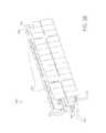
- FIG. 3Bis a perspective view of one embodiment of the foldable solar canopy structure of the invention when folded.
- FIG. 4is a side view of one embodiment of the foldable solar canopy structure of the invention unfolded and installed.
- FIG. 5Ais a perspective view of one embodiment of multiple foldable solar canopy structures of the invention unfolded.
- FIG. 5Bis a side-elevation view of one embodiment of the foldable solar canopy structure of the invention unfolded and installed.
- FIG. 6is a front elevation view of one embodiment of the foldable solar canopy structure of the invention unfolded.
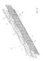
- FIG. 7is an isometric view of one embodiment of the foldable solar canopy structure of the invention unfolded.
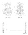
- FIG. 8is a side elevation view of an L-shaped embodiment of the foldable solar canopy structure of the invention unfolded.
- FIG. 9is a side elevation view of an L-shaped embodiment of the foldable solar canopy structure of the invention folded.
- FIG. 10is an isometric view of an L-shaped embodiment of the foldable solar canopy structure of the invention folded.
- FIG. 11Ais an inside elevation view of another embodiment of a portion of the folded foldable solar canopy structure and bracing of the invention.
- FIG. 11Bis an outside elevation view of another embodiment of a portion of the folded foldable solar canopy structure and bracing of the invention folded.
- FIG. 12is a side elevation view of another embodiment of a portion of the folded foldable solar canopy structure and bracing of the invention.
- FIG. 13is an isometric view of another embodiment of a portion of the folded foldable solar canopy structure and bracing of the invention folded.
- FIG. 14is an isometric/exploded view of another embodiment of the bracing of the invention.
- FIG. 15is an isometric/exploded view of another embodiment of the bracing of the invention.
- FIG. 16is an isometric/exploded view of another embodiment of the bracing of the invention.
- FIG. 17is a top/exploded view of another embodiment of the bracing of the invention.
- FIG. 18is a top/exploded view of another embodiment of a bracing element of the invention.
- the inventionincludes a one or two or multiple column photovoltaic shade structure which is fully assembled in a factory.
- This assemblyin some embodiments includes electrical panels, inverters, combiner boxes, lights, conduit, AC panel board or DC combiner, pull boxes, wire management components, strut, conduit, monitoring equipment and any other components which will be on the structure in the field.
- the assembled unitsare fully tested and partially commissioned in the factory before being shipped to the site for installation.
- the largest manufactured shade structureswould be up to approximately 40-50 feet plus long and weigh less than approximately 20,000 lbs.
- a horizontal beam for supporting channels and solar panelsis “broken (or articulated)”, in 3 locations; one in the center at the column and beam connection point.
- the other two broken locationsare outward from the center/column and before the two outer ends of the beam.
- the outer broken locationsare between the outer most solar panel and the adjacent solar panel.
- Hinges or other pivotable structuresare part of or attached to the broken portions of the beam.
- the hingesare built into the plate steel and use bolts or steel rods as the hinge point.
- the shipping, installation and transportation bracingis removed in the same order it was installed.
- the bracingcan also be adjusted on site to ensure footing and Manufactured Folding Photovoltaic Shade Structure column alignment.
- Benefits of the inventioninclude predictable/repeatable results, reduced financial risk, accuracy in scheduling, and accuracy in pricing.
- the benefitsalso include cost savings, leveraged scale to reduce cost, lower labor rates, manufacturing improvements in efficiency, enhanced procurement processes, refined and predictable pricing, controlled fabrication environment, and facilitates various design and construction tools.
- FIG. 1is one embodiment 100 of a flow chart for the process of manufacturing, transporting, and installing the foldable solar canopy structure of the invention.
- the foldable solar canopy structurealso referenced as the Folding Photovoltaic Shade Structure
- folding step 120cross-braces 322 (see, e.g., FIG. 3A ) are attached.
- the structureis folded and collapsed to prepare for transport to the installation site.
- the foldable solar canopy structureis loaded onto a transport vehicle (e.g., flat bed truck, barge, flat bed train car) for transport to the installation site. If the installation site is not prepared 140 , then the site is prepared 150 .
- a transport vehiclee.g., flat bed truck, barge, flat bed train car
- the foldable solar canopy structureis mounted 160 on the prepared site, i.e., mount columns on prepared bases.
- unfolding step 170the structure is unfolded and locked in position and any shipping brackets are removed.
- wiring step 180the electrical wiring is connected between the foldable solar canopy structure and any site electrical connection for distribution or storage of solar-produced electrical energy. This concludes 190 the method of constructing, transporting, and installing the foldable solar canopy structure.
- FIG. 2is one embodiment of a flow chart for the process of preparing the site prior to installing the foldable solar canopy structure 300 ( FIG. 3A ).
- the site for installation of the foldable solar canopy structureis prepared by a first grading and boring step 210 to level the ground as needed and bore holes for insertion of footing material, e.g., reinforced concrete, metal beam or column, or other now known or future developed footing materials.
- footing materiale.g., reinforced concrete, metal beam or column, or other now known or future developed footing materials.
- no footing holesare prepared and instead, e.g., a column or beam is forced into the ground.
- Any underground electrical infrastructure and other footing preparationsare then done 220 .
- the footing materialis concrete
- the concreteis then poured into the prepared footing holes, together with and reinforcement bars 230 .
- brackets or templatesshould be used to insure proper placement of the footing bolts.
- FIG. 3Ais a side view of one embodiment of the foldable solar canopy structure 300 when folded.
- Beam support columns 318are for attaching at the base to a footing (not shown).
- the beam support columns 318are removably attached to, e.g., reinforced concrete bollards by bolting the beam support columns 318 to the reinforced concrete bollards via bolts embedded in the concrete of the bollards and flanges 346 integral with the beam support columns 318 .
- Foldable Zee channel support beamshave a first section 314 for hingably attachment at an inner end (relative to the center of the structure) to the top of the beam support columns 318 via hinge flange 313 .
- the support beamsare made of tube steel.
- An outer end of first section 314hingably connects to a second section 317 of the Foldable Zee channel support beams via hinge flange 315 .
- the first section 314in one embodiment has sufficient length for at least two solar panels 310 side-by-side.
- the second section 317in one embodiment has sufficient length for at least one solar panel 310 .
- each solar panel 310 on each of the first section 314 and second section 317there are at least two Zee channels 312 attached with an axis substantially perpendicular to the axis of at least two Zee channel support beams sections 314 and 317 .
- the support beamsare referred to as “Zee channel” support beams, the types of channels or other support between the support beams and the solar panels may include any other known or future developed materials, e.g., C-channels or other suitable materials.
- Each Zee channel 312is of sufficient length to span two Zee channel support beams, 314 (first section) and 317 (second section), where the channel support first and second sections, 314 and 317 , are parallel and in line and set at a sufficient distance apart to accommodate a plurality of solar panels 310 end-to-end or side-by-side supported by the Zee channels 312 , which are supported by the channel support beams, first and second sections, 314 and 317 , which are supported by the beam support columns 318 , one beam support column 318 per each set of two channel support beams, first and second sections, 314 and 317 .
- each set of adjacent Zee channels 312is disposed in a reverse orientation to each adjacent Zee channel 312 .
- FIG. 3Bis a perspective view of one embodiment of the foldable solar canopy structure 300 when folded.
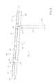
- FIG. 4is a side view of one embodiment of the foldable solar canopy structure of the invention unfolded and installed.
- the channel support beams first and second sections, 314 and 317in one embodiment area single beam with three or four hingable, foldable, pivotable, or collapsible sections.
- the channel support beams first and second sections, 314 and 317are two beams, each having two sections, first/inner section and second/outer section 314 and 317 , respectively.
- the sectionsare pivotably or hingably connected such that the beam(s) can either be folded or unfolded.
- the folded stateis used during transportation from the manufacturing site to the installation site.
- the unfolded stateis for the final operating configuration after installation.
- the hingable/pivotable connections within or between the channel support beams 314 and 317are any known or future developed means providing for folding or unfolding and locking in the unfolded position with sufficient structural integrity for the intended load and any desired safety margin.
- the hingable/pivotable connectionsare in one embodiment integral to the beams and in another embodiment a separate hinge component fixably attached to the beam.
- the inner/first sections 314will have integral or attached hinges on both ends, one for hingable connection to a top portion of the beam support column 318 and one for hingable connection to the inner end of the outer section 317 .
- the outer section 317has a hingable connection only at its inner end for hingable connection to the outer end of inner/first section 314 .
- Other configurationsare within the scope of the invention, e.g., 3-4 sections rather than 2 sections channel support beams first and second sections 314 and 317 .
- the height and width of the foldable solar canopy structure 300is sufficient for transportation on the intended mode of transportation, e.g., barge, truck, or train car.
- Braces 322are added as needed and optionally only during transportation, e.g., to maintain the folded state or to provide increased strength of the solar panels 310 to the Zee channels 312 to account for the sheer force that would not be present in the final unfolded state.
- the two channel support beams first and second sections 314 and 317one on each side of the beam support column 318 , form in effect a single beam aligned on the same axis and connected end-to-end.
- Ancillary electrical equipmentshown in other figures, e.g., FIG.
- AC panel board 319can be attached beneath the canopy, e.g., attached to a part of the beam support columns 318 or channel support beams first and second sections 314 or 317 .
- FIG. 5Ais a perspective view of one embodiment of a plurality of the foldable solar canopy structures 300 aligned end-to-end and unfolded and installed and attached to bollard/footing 320 .
- Any number, e.g., 10 , 20 , 50 , of foldable solar canopy structures 300may be aligned end-to-end to achieve the desired electric energy generation and to fit the available space at the site.
- the plurality of foldable solar canopy structures 300are electrically connected in series.
- the bollard/footing 320is above grade.
- the top of the bollard/footingis at grade.
- Ancillary electrical equipmente.g., a D.C.-A.C. inverter is attached beneath the canopy, e.g., attached to a part of channel support beams first and second sections 314 or 317 .
- FIG. 5Bis a side elevation view of one embodiment of the foldable solar canopy structure of the invention unfolded and installed.
- Beam support column 318supports the rest of the structure.
- Hinge flanges 313are attached to or integral with the top end of beam support column 318 .
- a foldable Zee channel support beam first and second sections ( 314 , 317 )is attached to a hinge flange 313 .
- the foldable Zee channel support beamsare comprised of a first section 314 proximate to the beam support column 318 and a second section 317 .
- the first and second sectionsare connected via hinge 315 which is integral to or attached to the first and section sections ( 314 and 317 ).
- the end of the first section proximate to the beam support column 318is connected to or integral with the hinges/hinge flanges 313 .
- the hinge flanges 313 and 315permit the foldable Zee channel support beams to fold downwards towards the ground.
- the foldable solar canopy structure 300In folded/collapsed position the foldable solar canopy structure 300 has a much smaller “footprint” or width making it a suitable size for transport via truck, barge, or train.
- Zee channels 312are fixedly attached at perpendicular angles to the foldable Zee channel support beams at their upper side.
- a plurality of solar panels 310are fixedly attached to the upper portions of the Zee channels 312 .
- each solar panel 310is attached such that its lengthwise axis is perpendicular to the lengthwise axis of the Zee channels 312 .
- the solar panels 310are spaced on the Zee channels 312 so as to be within a few inches or less of one another other on each side so as to maximize solar panel area for each structure.
- gapsare left between the solar panels over the channel support beams sufficient to permit attachment of braces (not shown) and for attachment of “toe” line or other line or cable for use in unfolding/expanding the foldable solar canopy structure 300 at the installation site.
- the hinge flanges 315 and 313release and lock using any conventional devices such as pins or bolts (not shown) which slide into place to prevent articulation of the hinge.
- Other mechanismsare latches connecting the 2 parts of the hinge.
- Other mechanismsare clasps, overlapping lips, interacting groves, and other known or future developed mechanisms.
- FIG. 6is a front elevation view of one embodiment of the foldable solar canopy structure of the invention unfolded and installed. It shows the plurality of Zee channels 312 supporting a plurality of solar panels 310 .
- FIG. 7is an isometric view of one embodiment of the foldable solar canopy structure of the invention unfolded and installed. In addition to the other elements of the structure, it shows the cross-brace 322 which in one embodiment connects in multiple locations between adjacent Zee channels 312 for structural stability. Light 324 is also depicted. Other components or accessories may also be attached under the expanded foldable solar canopy structure 300 , e.g., electrical boxes 319 , inverters 316 , or other control or measurement equipment 321 .
- FIG. 8is a side elevation view of an L-shaped embodiment of the foldable solar canopy structure 800 of the invention unfolded and installed.
- Beam support columns 318are for attaching at the base to a footing (not shown).
- the beam support columns 318are removably attached to, e.g., reinforced concrete bollards (not shown) by bolting the beam support columns 318 to the reinforced concrete bollards via bolts (not shown) embedded in the concrete of the bollards and flanges 346 integral with the beam support columns 318 .
- first and second sectionshave a first section 314 for hingably attachment at an inner end (relative to the center of the structure) on one side at the top of the beam support columns 318 via hinge flange 313 .
- the support beamsare made of tube steel.
- An outer end of first section 314hingably connects to a second section 317 of the Foldable Zee channel support beams via hinge flange 315 .
- the first section 314in one embodiment has sufficient length for at least two solar panels 310 side-by-side.
- the second section 317in one embodiment has sufficient length for at least one solar panel 310 .
- the opposing foldable Zee channel support beam ( 810 )has only one section, having a first end attached to hinge flange 313 and an opposite end not attached.
- first and second sections ( 314 and 317 ) and the other foldable Zee channel support beam ( 810 )there are at least two Zee channels 312 attached with an axis substantially perpendicular to the axis at least two Zee channel support beams sections, 314 and 317 , and 810 .
- the support beamsare referred to as “Zee channel” support beams, the types of channels or other support between the support beams and the solar panels may include any other known or future developed materials, e.g., C-channels or other suitable materials.
- Each Zee channel 312is of sufficient length to so that it spans two Zee channel support beams first and second sections 314 and 317 , and 810 , where the channel support beams first and second sections 314 and 317 , and 810 are parallel and in line and set at a sufficient distance apart to accommodate a plurality of solar panels 310 end-to-end or side-by-side supported by the Zee channels 312 , which are supported by the channel support beams first and second sections 314 and 317 , and 810 , which are supported by the beam support columns 318 , one beam support column 318 per each set of two channel support beams first section and second section 314 and 317 .
- each set of adjacent Zee channels 312is disposed in a reverse orientation to each adjacent Zee channel 312 .
- FIG. 9is a side elevation view of an L-shaped embodiment of the foldable solar canopy structure 800 of the invention folded. Since one of the channel support beams first and second sections 314 and 317 is longer than the other 810 , the former channel support beams extend farther down in the folded position.
- FIG. 10is an isometric view of an L-shaped embodiment of the foldable solar canopy structure of the invention folded.
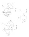
- FIG. 11Ais an inside elevation view of another embodiment of a portion of the folded foldable solar canopy structure and bracing of the invention 1300 .
- the solar panels 310are omitted for clarity.
- Brace assembly 1301is removably attached to beam support column 318 and to each of the channel support beams first and second sections 314 and 317 .
- the brace assembly 1301is for stabilizing the solar canopy structure 1300 during transport.
- Brace assembly 1301is comprised of a first and second brace clamp, here shown as single element 1310 , for removable attachment to each of the channel support beams first and second sections 314 and 317 , a third brace clamp 1315 for removable attachment to beam support column 318 , and a shock absorber 1317 for attaching the third brace clamp to each first and second brace clamp 1310 .
- shock absorber 1317is replaced with a fixed length strut.
- FIG. 11Bis an outside elevation view of another embodiment of a portion of the folded foldable solar canopy structure and bracing of the invention 1300 shown in FIG. 11A .
- the bracing assembly 1301is suitable for use with a folded foldable solar canopy structure 1300 having either a single or multiple beam support columns 318 . In one embodiment there is one bracing assembly 1301 for each beam support column 318 .
- FIGS. 11A and 11Bshow opposing views of a single beam support column 318 .
- FIG. 12is a side elevation view of another embodiment of a portion of the folded foldable solar canopy structure and bracing of the invention 1300 folded.
- This embodimenthas two beam support columns 318 .
- this embodimentdepicts an additional brace component, the support bar 1325 .
- Support bar 1325attaches at ends to the third brace clamp 1315 attached to each beam support column 318 .
- support bar 1325is a fixed length and in another embodiment it has a variable/adjustable length.
- support bar 1325joins the bottom portion of the two beam support columns 318 for maintaining a fixed spacing between the beam support columns, i.e., typically substantially equal at the top and bottom of the columns, so that the columns are substantially vertical. This facilitates installation at the site, i.e., where a foundation is prepared with bolts positioned for attachment of columns 318 .
- FIG. 13is an isometric view of another embodiment of a portion of the folded foldable solar canopy structure and bracing of the invention in the folded position.
- First and second brace clamps(jointly referenced here as 1310 ) attach to each of the channel support beams first and second sections 314 and 317 and to each other.
- the third brace clamp 1315attaches to beam support column 318 , and a strut/shock 1317 attaches to third brace clamp 1315 to each first and second brace clamp 1310 .
- Third brace clamp 1315has connection flanges 1330 for attachment to support bar 1325 .
- FIG. 14is an isometric/exploded view of another embodiment of the bracing of the invention.
- First and second brace clamps 1310in one embodiment is comprised of first brace clamp 1350 removable attached to second brace clamp 1370 .
- the attachmentin one embodiment is via attachment flanges 1385 on second brace clamp 1370 and mating flanges (not shown) on first brace clamp 1350 .
- Bolt/pin 1375passes through eyes in the attachment flanges to join them together. Other methods of removable attachment may be used.
- First brace clampcomprises two elements, i.e., first U-shaped body 1360 and shallow indented cover plate 1355 .
- Second brace clampcomprises two elements, i.e., second U-shaped body 1380 and flat cover plate 1365 .
- the U-shaped bodyremovably attaches to the respective cover plate, thus attaching to channel support beams first and second sections 314 and 317 .
- Third brace clamp 1315comprises two elements, i.e., third U-shaped body 1340 and flat cover plate 1345 .
- U-shaped body 1340removably attaches to the flat cover plate 1345 , thus attaching to support column 318 .
- Third brace clamp 1315removably attaches to second brace clamp 1370 via shock absorber 1317 or other strut, rod, or other suitable means.
- Shock absorber 1317removably attaches to third brace clamp 1315 via flange 1335 and a corresponding flange (not shown) on second brace clamp 1370 .
- FIGS. 15 , 16 , and 17are isometric/exploded views of one embodiment a portion of the bracing assembly 1301 .
- the respective U-shaped bodyattaches via bolts through holes (e.g., 1346 and 1347 ). Other attachment mechanisms may be used.
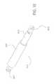
- FIG. 18is a top/exploded view of another embodiment of a bracing element of a portion of the bracing assembly 1301 ( FIG. 11A ).
- Shock absorber 1317is comprised of a first strut portion 1810 , second strut portion 1805 and connector flanges 1815 and 1817 .
- Other known connection methodsmay be used either rigid or designed to absorb shock.
Landscapes
- Engineering & Computer Science (AREA)
- Physics & Mathematics (AREA)
- Life Sciences & Earth Sciences (AREA)
- Sustainable Development (AREA)
- Sustainable Energy (AREA)
- Thermal Sciences (AREA)
- Chemical & Material Sciences (AREA)
- Combustion & Propulsion (AREA)
- Mechanical Engineering (AREA)
- General Engineering & Computer Science (AREA)
- Photovoltaic Devices (AREA)
Abstract
Description
- With respect to this material which is subject to copyright protection. The owner, Chevron Energy Solutions has no objection to the facsimile reproduction by any one of the patent disclosure, as it appears in the Patent and Trademark Office patent files or records of any country, but otherwise reserves all rights whatsoever.
Claims (1)
Priority Applications (1)
| Application Number | Priority Date | Filing Date | Title |
|---|---|---|---|
| US13/622,877US9093583B2 (en) | 2012-09-19 | 2012-09-19 | Folding solar canopy assembly |
Applications Claiming Priority (1)
| Application Number | Priority Date | Filing Date | Title |
|---|---|---|---|
| US13/622,877US9093583B2 (en) | 2012-09-19 | 2012-09-19 | Folding solar canopy assembly |
Publications (2)
| Publication Number | Publication Date |
|---|---|
| US20140076378A1 US20140076378A1 (en) | 2014-03-20 |
| US9093583B2true US9093583B2 (en) | 2015-07-28 |
Family
ID=50273191
Family Applications (1)
| Application Number | Title | Priority Date | Filing Date |
|---|---|---|---|
| US13/622,877Active2033-04-16US9093583B2 (en) | 2012-09-19 | 2012-09-19 | Folding solar canopy assembly |
Country Status (1)
| Country | Link |
|---|---|
| US (1) | US9093583B2 (en) |
Cited By (4)
| Publication number | Priority date | Publication date | Assignee | Title |
|---|---|---|---|---|
| CN105401782A (en)* | 2015-10-27 | 2016-03-16 | 杭州德宝机电制造有限公司 | Multifunctional cabinet and communication tower integrated combined device |
| WO2019241708A1 (en) | 2018-06-15 | 2019-12-19 | EvoluSun Inc. | Innovative energy generating photovoltaic awning |
| US20200390080A1 (en)* | 2019-06-13 | 2020-12-17 | Cnh Industrial America Llc | Inverted Truss Geometry For Agricultural Spray Boom |
| US20230276941A1 (en)* | 2020-09-16 | 2023-09-07 | Perfect Site LLC | Utility rack |
Families Citing this family (22)
| Publication number | Priority date | Publication date | Assignee | Title |
|---|---|---|---|---|
| US9093582B2 (en) | 2012-09-19 | 2015-07-28 | Opterra Energy Services, Inc. | Solar canopy assembly |
| US9093583B2 (en) | 2012-09-19 | 2015-07-28 | Opterra Energy Services, Inc. | Folding solar canopy assembly |
| US20140077055A1 (en) | 2012-09-19 | 2014-03-20 | Chevron U.S.A Inc.. | Bracing assembly |
| US9568900B2 (en) | 2012-12-11 | 2017-02-14 | Opterra Energy Services, Inc. | Systems and methods for regulating an alternative energy source that is decoupled from a power grid |
| JP6476740B2 (en) | 2014-10-23 | 2019-03-06 | 住友電気工業株式会社 | Solar power generation panel and method for manufacturing solar power generation apparatus |
| CN105227090A (en)* | 2015-09-30 | 2016-01-06 | 黑龙江兴安新能源股份有限公司 | A kind of with fascinating and the casing expansion solar panel carrying support body of lifting function |
| CN105227116A (en)* | 2015-09-30 | 2016-01-06 | 黑龙江兴安新能源股份有限公司 | A kind of with revolution and the folding and expanding formula solar power plant of lifting function |
| CN105227078B (en)* | 2015-09-30 | 2017-05-31 | 黑龙江兴安新能源股份有限公司 | Solar panel that is rotatable, launching carries support body |
| CN105227115A (en)* | 2015-09-30 | 2016-01-06 | 黑龙江兴安新能源股份有限公司 | A kind of with fascinating and the folding and expanding formula solar panel carrying support body of revolute function |
| CN105227112A (en)* | 2015-09-30 | 2016-01-06 | 黑龙江兴安新能源股份有限公司 | A kind of with revolution and the casing expansion solar panels support body of crank and rocker mechanism |
| JP6407914B2 (en)* | 2016-04-27 | 2018-10-17 | シャープ株式会社 | Solar cell mount, solar power generation system, and method for operating solar cell mount |
| US9874006B1 (en)* | 2016-08-01 | 2018-01-23 | Inhabit Solar, Llc | Modular roof mounting system |
| JP7129153B2 (en)* | 2017-09-01 | 2022-09-01 | シャープ株式会社 | Solar power system |
| JP6933715B2 (en)* | 2017-09-01 | 2021-09-08 | シャープ株式会社 | Solar power system |
| TR201810054A2 (en)* | 2018-07-14 | 2019-05-21 | Doga Panel Guenes Enerjisi Ve Elektrik Ueretimi Ithalat Ihracat Sanayi Ticaret Ltd Sirketi | DEVELOPMENT ON A MOBILE SOLAR POWER PLANT |
| USD909960S1 (en)* | 2018-11-14 | 2021-02-09 | Alexander Swatek | Solar power module |
| KR102095442B1 (en)* | 2019-06-11 | 2020-03-31 | 장영철 | solar power generator |
| NL2024420B1 (en)* | 2019-12-10 | 2021-08-31 | Axiturn B V | Foldable solar panel assembly |
| WO2022032349A1 (en)* | 2020-08-13 | 2022-02-17 | Eco Steel International Pty Ltd | A solar innovation system |
| CN114111866B (en)* | 2021-11-18 | 2024-02-20 | 贵州电网有限责任公司 | Rain cover for external monitoring equipment |
| WO2024234039A1 (en)* | 2023-05-12 | 2024-11-21 | RDB IP Pty Ltd | Solar awning |
| CN117277945B (en)* | 2023-11-13 | 2024-02-09 | 江苏福旭科技有限公司 | Photovoltaic power generation equipment convenient to shift |
Citations (159)
| Publication number | Priority date | Publication date | Assignee | Title |
|---|---|---|---|---|
| US816719A (en) | 1905-09-18 | 1906-04-03 | Henry L Fell | Fence-post. |
| US1284565A (en) | 1917-09-29 | 1918-11-12 | William T Bennett Jr | Fence-post base. |
| US1812585A (en) | 1928-09-21 | 1931-06-30 | Atlas Press Company | Engine stand |
| US1988389A (en) | 1933-01-06 | 1935-01-15 | Mioton Sidney Fitzhugh | Metallic building construction |
| US2018250A (en) | 1934-06-30 | 1935-10-22 | Morris J Cohan | Tube joint |
| US2098752A (en) | 1935-02-06 | 1937-11-09 | Fleetwings Inc | Structural section for aircraft |
| US2654147A (en) | 1949-09-02 | 1953-10-06 | Manufacturers And Traders Trus | Adapter features of motor stands |
| US2971736A (en) | 1958-10-18 | 1961-02-14 | Beteiligungs & Patentverw Gmbh | Support system for large area bodies |
| US3053359A (en) | 1960-03-21 | 1962-09-11 | Duo Flex Corp | Demountable acoustical ceiling |
| US3509674A (en) | 1966-05-13 | 1970-05-05 | Herbert L Birum Jr | Exterior wall accessories |
| US3557439A (en) | 1968-05-27 | 1971-01-26 | Fmc Corp | Pallet assembling system |
| US3620846A (en) | 1970-04-08 | 1971-11-16 | Nasa | Deployable solar cell array |
| US3643935A (en) | 1969-10-02 | 1972-02-22 | Archie Y Bell | Door-hanging workbench |
| US3741405A (en) | 1971-07-20 | 1973-06-26 | Interlake Inc | Load lock |
| US3946876A (en) | 1974-03-18 | 1976-03-30 | Jarke Corporation | Hinged post storage rack |
| US3969863A (en) | 1974-08-02 | 1976-07-20 | Alderman Robert J | Roof system |
| US4015653A (en) | 1976-04-08 | 1977-04-05 | General Dynamics Corporation | Panel deployment system |
| US4147414A (en)* | 1976-12-16 | 1979-04-03 | Raser William H | Sunlight concentrator for energy conversion |
| US4151872A (en) | 1977-12-21 | 1979-05-01 | General Dynamics Corporation | Panel deployment system |
| US4184476A (en) | 1977-08-26 | 1980-01-22 | Mcarthur William H | Solar energy collecting apparatus |
| US4206748A (en) | 1978-05-25 | 1980-06-10 | Libbey-Owens-Ford Company | Solar energy collector with collapsible supporting structure |
| US4253224A (en) | 1978-12-18 | 1981-03-03 | Brazeway, Inc. | Fixtureless method of making tube joints |
| US4255910A (en) | 1979-11-13 | 1981-03-17 | United States Gypsum Company | Accessible partition assembly |
| US4262809A (en) | 1978-10-13 | 1981-04-21 | Interlake, Inc. | Slotted beam and loadlock therefor |
| US4315163A (en) | 1980-09-16 | 1982-02-09 | Frank Bienville | Multipower electrical system for supplying electrical energy to a house or the like |
| US4393859A (en) | 1980-02-19 | 1983-07-19 | Armco Inc. | Solar collector roof |
| US4475296A (en) | 1980-09-22 | 1984-10-09 | Fremstad Gregory E | Fillet for picture frame |
| US4481774A (en) | 1978-01-18 | 1984-11-13 | Snook Stephen Robert | Solar canopy and solar augmented wind power station |
| US4621472A (en) | 1982-09-30 | 1986-11-11 | H. H. Robertson Company | Glazed structural system and components therefor |
| US4635413A (en) | 1984-10-11 | 1987-01-13 | Hong Sheet Metal Pte. Limited | Structural connectors and/or structures |
| US4659072A (en) | 1984-04-09 | 1987-04-21 | Rosa Roberto De | Knitting machine head extractor |
| US4909869A (en) | 1986-12-04 | 1990-03-20 | Mazda Motor Corporation | Method of mounting a window glass on a vehicle body |
| US4966631A (en) | 1989-03-13 | 1990-10-30 | Chronar Corp. | Support for photovoltaic arrays |
| US5125608A (en) | 1989-04-25 | 1992-06-30 | 700 Solar Club, Inc. | Photovoltaic panel support assembly |
| US5127638A (en) | 1991-03-11 | 1992-07-07 | Kent Cloyce G | Apparatus for removing wheel hubs from vehicle axles |
| DE4129492A1 (en) | 1991-09-05 | 1993-01-28 | Daimler Benz Ag | FASTENING A WINDOW IN A FLEXIBLE COVERING OF A FOLDING COVER |
| US5210685A (en) | 1985-03-08 | 1993-05-11 | Westinghouse Electric Corp. | Uninterruptible power supply system and load transfer static switch for such a system |
| US5233931A (en) | 1992-03-20 | 1993-08-10 | The Edinborough Company | Tray for transport and display of merchandise |
| US5355575A (en) | 1993-02-04 | 1994-10-18 | Self M L | Pallet moving device |
| US5433259A (en) | 1993-11-22 | 1995-07-18 | Carefree/Scott Fetzer Company | Retractable awning with integrated solar cells |
| US5460660A (en) | 1993-07-21 | 1995-10-24 | Photon Energy, Inc. | Apparatus for encapsulating a photovoltaic module |
| US5487471A (en) | 1994-10-19 | 1996-01-30 | Molex Incorporated | Packaging container assembly for electrical connector components |
| US5488810A (en) | 1993-08-24 | 1996-02-06 | Southeastern Metals Mfg. Co., Inc. | Post cap |
| US5499480A (en) | 1993-03-31 | 1996-03-19 | Bass; Kenneth R. | Lightweight metal truss and frame system |
| US5505788A (en) | 1994-06-29 | 1996-04-09 | Dinwoodie; Thomas L. | Thermally regulated photovoltaic roofing assembly |
| US5524401A (en) | 1993-01-12 | 1996-06-11 | Misawa Homes Co., Ltd. | Roof with solar battery |
| US5549287A (en) | 1994-06-14 | 1996-08-27 | Loucks; Howard C. | Automobile body parts holder assembly |
| US5571338A (en) | 1993-11-26 | 1996-11-05 | Sanyo Electric Co., Ltd. | Photovoltaic module and a photovoltaic apparatus |
| US5606838A (en) | 1995-05-23 | 1997-03-04 | Butler Manufacturing Company | Roof panel attachment clip with centering feature |
| US5716155A (en) | 1993-09-16 | 1998-02-10 | Honda Giken Kogyo Kabushiki Kaisha | T-shaped connection frame |
| US5741370A (en) | 1996-06-27 | 1998-04-21 | Evergreen Solar, Inc. | Solar cell modules with improved backskin and methods for forming same |
| US5814904A (en) | 1995-03-28 | 1998-09-29 | Cyberex, Inc. | Static switch method and apparatus |
| USD408554S (en) | 1997-06-25 | 1999-04-20 | Powerlight Corporation | Solar electric shade system |
| US5927138A (en) | 1997-10-21 | 1999-07-27 | Mcdonnell Douglas Corporation | Method of forming a structural member from tubular material |
| US5941035A (en) | 1997-09-03 | 1999-08-24 | Mega Building System Ltd. | Steel joist and concrete floor system |
| US6058601A (en) | 1998-07-27 | 2000-05-09 | Dekoning; Hubertus C. M. | Apparatus for automatic fence panel assembly |
| US6065255A (en) | 1998-12-07 | 2000-05-23 | Kyocera Solar, Inc. | Roof mounting for photovoltaic modules |
| US6082060A (en) | 1996-08-12 | 2000-07-04 | Siemens Solar Gmbh | Device for affixing a flat plate-shaped body onto a support |
| US6155017A (en) | 1996-11-04 | 2000-12-05 | Powertrusion 2000 | Truss structure |
| US6182403B1 (en) | 1996-08-30 | 2001-02-06 | Canon Kabushiki Kaisha | Combination solar battery and roof unit and mounting method thereof |
| US6308489B1 (en) | 2000-02-23 | 2001-10-30 | Guardian Fiberglass, Inc. | Rolled fabric dispensing apparatus |
| US6404075B1 (en) | 2000-01-18 | 2002-06-11 | Chevron Energy Solutions, L.P. | Uninterruptible power generation system |
| US6465724B1 (en) | 1998-07-28 | 2002-10-15 | Bp Solar International Llc | Photovoltaic module framing system with integral electrical raceways |
| US6470632B1 (en) | 2000-11-04 | 2002-10-29 | Arthur E. Smith | Modified A-frame building and truss for same |
| US20030070368A1 (en) | 2001-10-12 | 2003-04-17 | Jefferson Shingleton | Solar module mounting method and clip |
| US20030070705A1 (en) | 2001-10-11 | 2003-04-17 | Hayden Herbert T. | Structure for supporting a photovoltaic module in a solar energy collection system |
| US20030101662A1 (en) | 2000-01-14 | 2003-06-05 | Ullman Stanley A. | Mounting system for supporting objects |
| US20030177706A1 (en) | 2000-01-14 | 2003-09-25 | Ullman Stanley A. | Mounting system for supporting objects |
| US6654998B1 (en) | 1999-02-11 | 2003-12-02 | Spx Corporation | Method of installing plates on blade of plow or grader |
| US20040011354A1 (en) | 2000-04-04 | 2004-01-22 | Erling Peter Stuart | Framing system for solar panels |
| US6685390B1 (en) | 2002-04-15 | 2004-02-03 | Wayne Eitzen | Inverted truss screed with outrigger support |
| US6722357B2 (en) | 2001-08-15 | 2004-04-20 | Powerlight Corporation | Fixed angle solar collector arrangement |
| US20050109384A1 (en) | 2003-03-10 | 2005-05-26 | Powerlight Corporation | Modular shade system with solar tracking panels |
| US20060096635A1 (en) | 2004-11-10 | 2006-05-11 | Daystar Technologies, Inc. | Pallet based system for forming thin-film solar cells |
| EP1683728A1 (en) | 2005-01-19 | 2006-07-26 | Josefina Mondejar Jiménez | Pile-up container for storing and transporting components with a generally planar configuration. |
| US20060171086A1 (en) | 2005-02-01 | 2006-08-03 | Vrb Power Systems Inc. | Method for retrofitting wind turbine farms |
| US7102074B2 (en) | 2003-09-10 | 2006-09-05 | Kuo-Yow Yen | Photovoltaic attachment system |
| US20060219547A1 (en) | 2004-11-10 | 2006-10-05 | Daystar Technologies, Inc. | Vertical production of photovoltaic devices |
| US20060276938A1 (en) | 2005-06-06 | 2006-12-07 | Equinox Energy Solutions, Inc. | Optimized energy management system |
| US7171793B2 (en) | 1990-01-31 | 2007-02-06 | Musco Corporation | Means and method for rigidly elevating a structure |
| US7230819B2 (en) | 2002-09-13 | 2007-06-12 | Skybuilt Power, Llc | Mobile power system |
| US7237360B2 (en) | 2003-09-23 | 2007-07-03 | Cemusa, Inc. | Shelter |
| US7260918B2 (en) | 2001-07-20 | 2007-08-28 | Unirac, Inc. | Apparatus and method for positioning a module on an object |
| US20070246039A1 (en) | 2006-03-31 | 2007-10-25 | Shay Brazier | Solar array mounting system |
| US20080029148A1 (en) | 2004-10-29 | 2008-02-07 | Thompson Daniel S | Floating support structure for a solar panel array |
| WO2008058284A2 (en) | 2006-11-09 | 2008-05-15 | Gridpoint, Inc. | Energy arbitrage by load shifting |
| EP1947019A2 (en) | 2007-01-19 | 2008-07-23 | Söhner Kunststofftechnik GmbH | Transport and protection device |
| WO2008088311A2 (en)* | 2006-12-28 | 2008-07-24 | Bosley Brian W | Solar panel mounting apparatus with a plurality of independtently adjustable arms and rotatable vertical axis |
| US20080230047A1 (en) | 2007-03-23 | 2008-09-25 | Sunpower Corporation | Stackable Tracking Solar Collector Assembly |
| US20080236571A1 (en) | 2007-03-28 | 2008-10-02 | Keshner Marvin S | Solar panel system and method utilizing unframed solar panels |
| US7487771B1 (en) | 2004-09-24 | 2009-02-10 | Imaginit, Inc. | Solar panel frame assembly and method for forming an array of connected and framed solar panels |
| US20090050194A1 (en) | 2007-08-21 | 2009-02-26 | Noble Robert L | Support system for a photovoltaic system |
| US20090090404A1 (en)* | 2001-02-07 | 2009-04-09 | World Factory, Inc | Umbrella Apparatus |
| US7531741B1 (en) | 2003-03-07 | 2009-05-12 | Sacred Power Corporation | Tracking solar shelter |
| US20090140576A1 (en) | 2007-11-30 | 2009-06-04 | Caterpillar Inc. | Hybrid power system with variable speed genset |
| USD595648S1 (en) | 2008-03-04 | 2009-07-07 | Sew-Eurodrive Gmbh & Co. Kg | Motor |
| US20090205703A1 (en) | 2008-02-14 | 2009-08-20 | Applied Materials, Inc. | Apparatus and method of mounting and supporting a solar panel |
| US20090230265A1 (en) | 2008-03-17 | 2009-09-17 | Michael Newman | Mounting System for Photovoltaic Panels |
| US20090229200A1 (en) | 2008-03-11 | 2009-09-17 | Robert Noble | Photovoltaic System and Method |
| US7600349B2 (en) | 2003-02-26 | 2009-10-13 | Unirac, Inc. | Low profile mounting system |
| US7607628B2 (en) | 2002-04-03 | 2009-10-27 | Stratis Corporation | Pallet |
| US20090282755A1 (en) | 2008-05-19 | 2009-11-19 | Powermount Systems, Inc. | Photovoltaic mounting system with locking connectors, adjustable rail height and hinge lock |
| US20090314327A1 (en) | 2008-06-24 | 2009-12-24 | Moser Baer Photovoltaic Limited | Photovoltaic module |
| US20100031586A1 (en) | 2008-06-10 | 2010-02-11 | Project Frog, Inc. | Roof joist for modular building and methods |
| US20100073220A1 (en) | 2008-09-23 | 2010-03-25 | Infineon Technologies Ag | Self calibration method for radio equipment with receive and transmit circuitry |
| US20100077592A1 (en) | 2008-10-01 | 2010-04-01 | Peter Casano | System and method for hanging solar panels from a horizontal support |
| US20100083954A1 (en) | 2007-03-30 | 2010-04-08 | Haticon Gmbh | Fixture for solar modules |
| DE202010001742U1 (en) | 2009-02-03 | 2010-05-06 | Net Neue Energie Technik Gmbh | Feeding device for an AC mains |
| US20100108118A1 (en) | 2008-06-02 | 2010-05-06 | Daniel Luch | Photovoltaic power farm structure and installation |
| US20100132768A1 (en) | 2007-05-14 | 2010-06-03 | Mitsubishi Electric Corporation | Solar Cell Module |
| US20100132769A1 (en)* | 2009-10-23 | 2010-06-03 | Chevron U.S.A. Inc. | Solar canopy support system |
| US7743575B2 (en) | 2006-04-24 | 2010-06-29 | Nichiha Co., Ltd. | Joint member |
| US20100163015A1 (en) | 2009-10-23 | 2010-07-01 | Chevron U.S.A. Inc. | Solar canopy connector system |
| US20100179704A1 (en) | 2009-01-14 | 2010-07-15 | Integral Analytics, Inc. | Optimization of microgrid energy use and distribution |
| US20100193260A1 (en) | 2009-02-03 | 2010-08-05 | Benjamin Freeman | Electric car with maximized solar assist |
| US7774998B2 (en) | 2004-03-15 | 2010-08-17 | Sunpower Corporation | Ventilated photovoltaic module frame |
| US20100212722A1 (en) | 2009-02-24 | 2010-08-26 | Wares Brian S | Photovoltaic Module and Interlocked Stack of Photovoltaic Modules |
| US20100236183A1 (en) | 2009-03-20 | 2010-09-23 | Northern States Metals Company | Support System for Solar Panels |
| US20100237029A1 (en) | 2009-03-20 | 2010-09-23 | Northern States Metals Company | Support System For Solar Panels |
| US20100254813A1 (en) | 2009-04-02 | 2010-10-07 | Frontier Pro Services | Winch servicing of wind turbines |
| US7810489B2 (en) | 2007-11-02 | 2010-10-12 | Fu Zhun Precision Industry (Shen Zhen) Co., Ltd. | Solar air conditioner |
| US7814899B1 (en) | 2006-07-04 | 2010-10-19 | Jonathan Port | Solar panel mounting systems |
| US20100313939A1 (en) | 2009-06-12 | 2010-12-16 | Miasole | Systems methods and apparatuses for magnetic processing of solar modules |
| US20100317141A1 (en) | 2009-06-12 | 2010-12-16 | Miasole | Systems, methods and apparatuses for magnetic processing of solar modules |
| US7856769B2 (en) | 2004-02-13 | 2010-12-28 | Pvt Solar, Inc. | Rack assembly for mounting solar modules |
| US20110005573A1 (en)* | 2009-07-07 | 2011-01-13 | POWER LIGHT Tech. Co., Ltd. | Foldable solar energy apparatus |
| DE102009033946A1 (en) | 2009-07-13 | 2011-01-20 | Dr. Doll Holding Gmbh | Flat panel object e.g. photovoltaic module, absorbing device in transport container has sides of plug-in module provided with plug-in receiver for receiving panel item, where module and another module are retained on mutual-supporting units |
| US20110036386A1 (en)* | 2009-08-17 | 2011-02-17 | Browder John H | Solar panel with inverter |
| US20110047931A1 (en) | 2008-05-01 | 2011-03-03 | Sunedison, Llc | Methods of Assembling Solar Energy Collecting Modules |
| US20110058664A1 (en) | 2009-09-09 | 2011-03-10 | Sundial Power Pods, Llc | Mobile power system |
| DE102009040091A1 (en) | 2009-09-04 | 2011-03-10 | Voltwerk Electronics Gmbh | Island unit of an island power network for communicating energy requests with another island unit |
| US20110072740A1 (en) | 2009-09-29 | 2011-03-31 | Dieter David B | Concrete photovoltaic system |
| US20110094559A1 (en) | 2009-10-23 | 2011-04-28 | Chevron U.S.A. Inc. | Solar canopy support system |
| US20110113714A1 (en) | 2006-06-20 | 2011-05-19 | New Jersey Institute Of Technology | System and Method of Use for Composite Floor |
| US20110138599A1 (en) | 2010-07-29 | 2011-06-16 | John Bellacicco | Mounting system supporting slidable installation of a plurality of solar panels as a unit |
| US20110236183A1 (en) | 2010-03-25 | 2011-09-29 | General Electric Company | Bimetallic spline seal |
| US20110240093A1 (en)* | 2011-06-17 | 2011-10-06 | Phat Energy | Solar power structure |
| DE202011005048U1 (en) | 2011-04-08 | 2011-10-11 | Rudolf Baier | Electrical power distribution device for a building |
| US20110284709A1 (en) | 2010-05-24 | 2011-11-24 | CHEVRON ENERGY SOLUTIONS COMPANY, a division of CHEVRON U.S.A. INC. | Solar module array pre-assembly method and apparatus |
| US20110283923A1 (en) | 2010-05-24 | 2011-11-24 | CHEVRON ENERGY SOLUTIONS COMPANY, a division of CHEVRON U.S.A. INC. | Pallet assembly for transport of solar module array pre-assembly |
| US20120027550A1 (en) | 2010-07-29 | 2012-02-02 | John Bellacicco | Automated installation system for and method of deployment of photovoltaic solar panels |
| US20120198696A1 (en) | 2011-02-08 | 2012-08-09 | Chevron Usa Inc. | Solar string assembly process |
| DE102012202465A1 (en) | 2011-02-21 | 2012-08-23 | Denso Corporation | Power supply system for supplying electric current to e.g. house to charge battery of hybrid car, has storage device storing surplus of electric solar when amount of electricity is larger than amount of electric current consumed by load |
| US20120229077A1 (en) | 2011-03-07 | 2012-09-13 | Denso Corporation | Electric power supply system and method for controlling electric power discharge |
| EP2509180A1 (en) | 2009-11-30 | 2012-10-10 | Kyocera Corporation | Control apparatus and control method |
| US8316590B2 (en) | 2009-03-20 | 2012-11-27 | Northern States Metals Company | Support system for solar panels |
| US8430372B2 (en) | 2007-06-06 | 2013-04-30 | Robert M. M. Haddock | Adjustable mounting assembly for standing seam panels |
| US20130122639A1 (en) | 2010-07-30 | 2013-05-16 | Marty W. Degroot | Automated assembly method for the production of interconnected thin film solar cell modules |
| US8453986B2 (en) | 2009-01-27 | 2013-06-04 | Mounting Systems Gmbh | Solar panel mount |
| US8657991B2 (en) | 2011-02-08 | 2014-02-25 | Chevron U.S.A. Inc. | Robotic solar panel string assembly process |
| US20140076377A1 (en) | 2012-09-19 | 2014-03-20 | Chevron U.S.A. Inc. | Solar canopy assembly |
| US20140076378A1 (en) | 2012-09-19 | 2014-03-20 | Chevron U.S.A Inc. | Folding solar canopy assembly |
| US20140076383A1 (en) | 2010-05-24 | 2014-03-20 | Chevron U.S.A. Inc. | Solar module array pre-assembly method and apparatus |
| US20140077055A1 (en) | 2012-09-19 | 2014-03-20 | Chevron U.S.A Inc.. | Bracing assembly |
| US20140163755A1 (en) | 2012-12-11 | 2014-06-12 | Chevron Usa Inc. | Systems and methods for improving generator efficiency in an isolated power consumption system |
| US20140163756A1 (en) | 2012-12-11 | 2014-06-12 | Chevron Usa Inc. | Systems and methods for minimizing energy costs for a power consumption system that has access to off-grid resources |
| US20140163754A1 (en) | 2012-12-11 | 2014-06-12 | Chevron Usa Inc. | Systems and methods for regulating an alternative energy source that is decoupled from a power grid |
| EP2469238A3 (en) | 2010-12-21 | 2014-07-09 | Werner Atzenhofer | Photovoltaic device |
| US8839500B2 (en) | 2011-02-08 | 2014-09-23 | Chevron U.S.A. Inc. | Edge conveyor belt solar string assembly device |
- 2012
- 2012-09-19USUS13/622,877patent/US9093583B2/enactiveActive
Patent Citations (178)
| Publication number | Priority date | Publication date | Assignee | Title |
|---|---|---|---|---|
| US816719A (en) | 1905-09-18 | 1906-04-03 | Henry L Fell | Fence-post. |
| US1284565A (en) | 1917-09-29 | 1918-11-12 | William T Bennett Jr | Fence-post base. |
| US1812585A (en) | 1928-09-21 | 1931-06-30 | Atlas Press Company | Engine stand |
| US1988389A (en) | 1933-01-06 | 1935-01-15 | Mioton Sidney Fitzhugh | Metallic building construction |
| US2018250A (en) | 1934-06-30 | 1935-10-22 | Morris J Cohan | Tube joint |
| US2098752A (en) | 1935-02-06 | 1937-11-09 | Fleetwings Inc | Structural section for aircraft |
| US2654147A (en) | 1949-09-02 | 1953-10-06 | Manufacturers And Traders Trus | Adapter features of motor stands |
| US2971736A (en) | 1958-10-18 | 1961-02-14 | Beteiligungs & Patentverw Gmbh | Support system for large area bodies |
| US3053359A (en) | 1960-03-21 | 1962-09-11 | Duo Flex Corp | Demountable acoustical ceiling |
| US3509674A (en) | 1966-05-13 | 1970-05-05 | Herbert L Birum Jr | Exterior wall accessories |
| US3557439A (en) | 1968-05-27 | 1971-01-26 | Fmc Corp | Pallet assembling system |
| US3643935A (en) | 1969-10-02 | 1972-02-22 | Archie Y Bell | Door-hanging workbench |
| US3620846A (en) | 1970-04-08 | 1971-11-16 | Nasa | Deployable solar cell array |
| US3741405A (en) | 1971-07-20 | 1973-06-26 | Interlake Inc | Load lock |
| US3946876A (en) | 1974-03-18 | 1976-03-30 | Jarke Corporation | Hinged post storage rack |
| US3969863A (en) | 1974-08-02 | 1976-07-20 | Alderman Robert J | Roof system |
| US4015653A (en) | 1976-04-08 | 1977-04-05 | General Dynamics Corporation | Panel deployment system |
| US4147414A (en)* | 1976-12-16 | 1979-04-03 | Raser William H | Sunlight concentrator for energy conversion |
| US4184476A (en) | 1977-08-26 | 1980-01-22 | Mcarthur William H | Solar energy collecting apparatus |
| US4151872A (en) | 1977-12-21 | 1979-05-01 | General Dynamics Corporation | Panel deployment system |
| US4481774A (en) | 1978-01-18 | 1984-11-13 | Snook Stephen Robert | Solar canopy and solar augmented wind power station |
| US4206748A (en) | 1978-05-25 | 1980-06-10 | Libbey-Owens-Ford Company | Solar energy collector with collapsible supporting structure |
| US4262809A (en) | 1978-10-13 | 1981-04-21 | Interlake, Inc. | Slotted beam and loadlock therefor |
| US4253224A (en) | 1978-12-18 | 1981-03-03 | Brazeway, Inc. | Fixtureless method of making tube joints |
| US4255910A (en) | 1979-11-13 | 1981-03-17 | United States Gypsum Company | Accessible partition assembly |
| US4393859A (en) | 1980-02-19 | 1983-07-19 | Armco Inc. | Solar collector roof |
| US4315163A (en) | 1980-09-16 | 1982-02-09 | Frank Bienville | Multipower electrical system for supplying electrical energy to a house or the like |
| US4475296A (en) | 1980-09-22 | 1984-10-09 | Fremstad Gregory E | Fillet for picture frame |
| US4621472A (en) | 1982-09-30 | 1986-11-11 | H. H. Robertson Company | Glazed structural system and components therefor |
| US4659072A (en) | 1984-04-09 | 1987-04-21 | Rosa Roberto De | Knitting machine head extractor |
| US4635413A (en) | 1984-10-11 | 1987-01-13 | Hong Sheet Metal Pte. Limited | Structural connectors and/or structures |
| US5210685A (en) | 1985-03-08 | 1993-05-11 | Westinghouse Electric Corp. | Uninterruptible power supply system and load transfer static switch for such a system |
| US4909869A (en) | 1986-12-04 | 1990-03-20 | Mazda Motor Corporation | Method of mounting a window glass on a vehicle body |
| US4966631A (en) | 1989-03-13 | 1990-10-30 | Chronar Corp. | Support for photovoltaic arrays |
| US5125608A (en) | 1989-04-25 | 1992-06-30 | 700 Solar Club, Inc. | Photovoltaic panel support assembly |
| US7171793B2 (en) | 1990-01-31 | 2007-02-06 | Musco Corporation | Means and method for rigidly elevating a structure |
| US5127638A (en) | 1991-03-11 | 1992-07-07 | Kent Cloyce G | Apparatus for removing wheel hubs from vehicle axles |
| DE4129492A1 (en) | 1991-09-05 | 1993-01-28 | Daimler Benz Ag | FASTENING A WINDOW IN A FLEXIBLE COVERING OF A FOLDING COVER |
| US5233931A (en) | 1992-03-20 | 1993-08-10 | The Edinborough Company | Tray for transport and display of merchandise |
| US5524401A (en) | 1993-01-12 | 1996-06-11 | Misawa Homes Co., Ltd. | Roof with solar battery |
| US5355575A (en) | 1993-02-04 | 1994-10-18 | Self M L | Pallet moving device |
| US5499480A (en) | 1993-03-31 | 1996-03-19 | Bass; Kenneth R. | Lightweight metal truss and frame system |
| US5460660A (en) | 1993-07-21 | 1995-10-24 | Photon Energy, Inc. | Apparatus for encapsulating a photovoltaic module |
| US5488810A (en) | 1993-08-24 | 1996-02-06 | Southeastern Metals Mfg. Co., Inc. | Post cap |
| US5716155A (en) | 1993-09-16 | 1998-02-10 | Honda Giken Kogyo Kabushiki Kaisha | T-shaped connection frame |
| US5433259A (en) | 1993-11-22 | 1995-07-18 | Carefree/Scott Fetzer Company | Retractable awning with integrated solar cells |
| US5571338A (en) | 1993-11-26 | 1996-11-05 | Sanyo Electric Co., Ltd. | Photovoltaic module and a photovoltaic apparatus |
| US5549287A (en) | 1994-06-14 | 1996-08-27 | Loucks; Howard C. | Automobile body parts holder assembly |
| US5505788A (en) | 1994-06-29 | 1996-04-09 | Dinwoodie; Thomas L. | Thermally regulated photovoltaic roofing assembly |
| US5487471A (en) | 1994-10-19 | 1996-01-30 | Molex Incorporated | Packaging container assembly for electrical connector components |
| US5814904A (en) | 1995-03-28 | 1998-09-29 | Cyberex, Inc. | Static switch method and apparatus |
| US5606838A (en) | 1995-05-23 | 1997-03-04 | Butler Manufacturing Company | Roof panel attachment clip with centering feature |
| US5741370A (en) | 1996-06-27 | 1998-04-21 | Evergreen Solar, Inc. | Solar cell modules with improved backskin and methods for forming same |
| US6082060A (en) | 1996-08-12 | 2000-07-04 | Siemens Solar Gmbh | Device for affixing a flat plate-shaped body onto a support |
| US6182403B1 (en) | 1996-08-30 | 2001-02-06 | Canon Kabushiki Kaisha | Combination solar battery and roof unit and mounting method thereof |
| US6155017A (en) | 1996-11-04 | 2000-12-05 | Powertrusion 2000 | Truss structure |
| USD408554S (en) | 1997-06-25 | 1999-04-20 | Powerlight Corporation | Solar electric shade system |
| US5941035A (en) | 1997-09-03 | 1999-08-24 | Mega Building System Ltd. | Steel joist and concrete floor system |
| US5927138A (en) | 1997-10-21 | 1999-07-27 | Mcdonnell Douglas Corporation | Method of forming a structural member from tubular material |
| US6058601A (en) | 1998-07-27 | 2000-05-09 | Dekoning; Hubertus C. M. | Apparatus for automatic fence panel assembly |
| US6465724B1 (en) | 1998-07-28 | 2002-10-15 | Bp Solar International Llc | Photovoltaic module framing system with integral electrical raceways |
| US6065255A (en) | 1998-12-07 | 2000-05-23 | Kyocera Solar, Inc. | Roof mounting for photovoltaic modules |
| US6654998B1 (en) | 1999-02-11 | 2003-12-02 | Spx Corporation | Method of installing plates on blade of plow or grader |
| US20030101662A1 (en) | 2000-01-14 | 2003-06-05 | Ullman Stanley A. | Mounting system for supporting objects |
| US20030177706A1 (en) | 2000-01-14 | 2003-09-25 | Ullman Stanley A. | Mounting system for supporting objects |
| US20020109411A1 (en) | 2000-01-18 | 2002-08-15 | Potter David S. | Uninterruptible power generation system |
| US6404075B1 (en) | 2000-01-18 | 2002-06-11 | Chevron Energy Solutions, L.P. | Uninterruptible power generation system |
| US6308489B1 (en) | 2000-02-23 | 2001-10-30 | Guardian Fiberglass, Inc. | Rolled fabric dispensing apparatus |
| US20040011354A1 (en) | 2000-04-04 | 2004-01-22 | Erling Peter Stuart | Framing system for solar panels |
| US7012188B2 (en) | 2000-04-04 | 2006-03-14 | Peter Stuart Erling | Framing system for solar panels |
| US6470632B1 (en) | 2000-11-04 | 2002-10-29 | Arthur E. Smith | Modified A-frame building and truss for same |
| US20090090404A1 (en)* | 2001-02-07 | 2009-04-09 | World Factory, Inc | Umbrella Apparatus |
| US7766292B2 (en) | 2001-07-20 | 2010-08-03 | Unirac, Inc. | System for mounting a photovoltaic module to a surface |
| US7260918B2 (en) | 2001-07-20 | 2007-08-28 | Unirac, Inc. | Apparatus and method for positioning a module on an object |
| US6722357B2 (en) | 2001-08-15 | 2004-04-20 | Powerlight Corporation | Fixed angle solar collector arrangement |
| US20030070705A1 (en) | 2001-10-11 | 2003-04-17 | Hayden Herbert T. | Structure for supporting a photovoltaic module in a solar energy collection system |
| US20030070368A1 (en) | 2001-10-12 | 2003-04-17 | Jefferson Shingleton | Solar module mounting method and clip |
| US6672018B2 (en) | 2001-10-12 | 2004-01-06 | Jefferson Shingleton | Solar module mounting method and clip |
| US7607628B2 (en) | 2002-04-03 | 2009-10-27 | Stratis Corporation | Pallet |
| US6685390B1 (en) | 2002-04-15 | 2004-02-03 | Wayne Eitzen | Inverted truss screed with outrigger support |
| US7230819B2 (en) | 2002-09-13 | 2007-06-12 | Skybuilt Power, Llc | Mobile power system |
| US8640400B2 (en) | 2003-02-26 | 2014-02-04 | Unirac, Inc. | Low profile mounting system |
| US7600349B2 (en) | 2003-02-26 | 2009-10-13 | Unirac, Inc. | Low profile mounting system |
| US7531741B1 (en) | 2003-03-07 | 2009-05-12 | Sacred Power Corporation | Tracking solar shelter |
| US7557292B2 (en) | 2003-03-10 | 2009-07-07 | Sunpower Corporation, Systems | Modular shade system with solar tracking panels |
| US7807918B2 (en) | 2003-03-10 | 2010-10-05 | Sunpower Corporation, Systems | Modular shade system |
| US20050109384A1 (en) | 2003-03-10 | 2005-05-26 | Powerlight Corporation | Modular shade system with solar tracking panels |
| US20090223142A1 (en) | 2003-03-10 | 2009-09-10 | Sunpower Corporation, Systems | Modular Shade System with Solar Tracking Panels |
| US7102074B2 (en) | 2003-09-10 | 2006-09-05 | Kuo-Yow Yen | Photovoltaic attachment system |
| US7237360B2 (en) | 2003-09-23 | 2007-07-03 | Cemusa, Inc. | Shelter |
| US7856769B2 (en) | 2004-02-13 | 2010-12-28 | Pvt Solar, Inc. | Rack assembly for mounting solar modules |
| US7774998B2 (en) | 2004-03-15 | 2010-08-17 | Sunpower Corporation | Ventilated photovoltaic module frame |
| US7487771B1 (en) | 2004-09-24 | 2009-02-10 | Imaginit, Inc. | Solar panel frame assembly and method for forming an array of connected and framed solar panels |
| US20080029148A1 (en) | 2004-10-29 | 2008-02-07 | Thompson Daniel S | Floating support structure for a solar panel array |
| WO2006053128A8 (en) | 2004-11-10 | 2007-12-21 | Daystar Technologies Inc | Pallet based system for forming thin-film solar cells |
| US20060219547A1 (en) | 2004-11-10 | 2006-10-05 | Daystar Technologies, Inc. | Vertical production of photovoltaic devices |
| US20060096635A1 (en) | 2004-11-10 | 2006-05-11 | Daystar Technologies, Inc. | Pallet based system for forming thin-film solar cells |
| EP1683728A1 (en) | 2005-01-19 | 2006-07-26 | Josefina Mondejar Jiménez | Pile-up container for storing and transporting components with a generally planar configuration. |
| US20060171086A1 (en) | 2005-02-01 | 2006-08-03 | Vrb Power Systems Inc. | Method for retrofitting wind turbine farms |
| US20060276938A1 (en) | 2005-06-06 | 2006-12-07 | Equinox Energy Solutions, Inc. | Optimized energy management system |
| US20070246039A1 (en) | 2006-03-31 | 2007-10-25 | Shay Brazier | Solar array mounting system |
| US7743575B2 (en) | 2006-04-24 | 2010-06-29 | Nichiha Co., Ltd. | Joint member |
| US20110113714A1 (en) | 2006-06-20 | 2011-05-19 | New Jersey Institute Of Technology | System and Method of Use for Composite Floor |
| US7814899B1 (en) | 2006-07-04 | 2010-10-19 | Jonathan Port | Solar panel mounting systems |
| WO2008058284A2 (en) | 2006-11-09 | 2008-05-15 | Gridpoint, Inc. | Energy arbitrage by load shifting |
| WO2008088311A2 (en)* | 2006-12-28 | 2008-07-24 | Bosley Brian W | Solar panel mounting apparatus with a plurality of independtently adjustable arms and rotatable vertical axis |
| EP1947019A2 (en) | 2007-01-19 | 2008-07-23 | Söhner Kunststofftechnik GmbH | Transport and protection device |
| US20080230047A1 (en) | 2007-03-23 | 2008-09-25 | Sunpower Corporation | Stackable Tracking Solar Collector Assembly |
| US20080236571A1 (en) | 2007-03-28 | 2008-10-02 | Keshner Marvin S | Solar panel system and method utilizing unframed solar panels |
| US20100083954A1 (en) | 2007-03-30 | 2010-04-08 | Haticon Gmbh | Fixture for solar modules |
| US20100132768A1 (en) | 2007-05-14 | 2010-06-03 | Mitsubishi Electric Corporation | Solar Cell Module |
| US8430372B2 (en) | 2007-06-06 | 2013-04-30 | Robert M. M. Haddock | Adjustable mounting assembly for standing seam panels |
| US20090050194A1 (en) | 2007-08-21 | 2009-02-26 | Noble Robert L | Support system for a photovoltaic system |
| US7810489B2 (en) | 2007-11-02 | 2010-10-12 | Fu Zhun Precision Industry (Shen Zhen) Co., Ltd. | Solar air conditioner |
| US20090140576A1 (en) | 2007-11-30 | 2009-06-04 | Caterpillar Inc. | Hybrid power system with variable speed genset |
| US20090205703A1 (en) | 2008-02-14 | 2009-08-20 | Applied Materials, Inc. | Apparatus and method of mounting and supporting a solar panel |
| USD595648S1 (en) | 2008-03-04 | 2009-07-07 | Sew-Eurodrive Gmbh & Co. Kg | Motor |
| US20090229200A1 (en) | 2008-03-11 | 2009-09-17 | Robert Noble | Photovoltaic System and Method |
| US20090230265A1 (en) | 2008-03-17 | 2009-09-17 | Michael Newman | Mounting System for Photovoltaic Panels |
| US20110198304A1 (en) | 2008-05-01 | 2011-08-18 | Linus Eric Wallgren | Rack Assembly for Solar Energy Collecting Module |
| US20110047931A1 (en) | 2008-05-01 | 2011-03-03 | Sunedison, Llc | Methods of Assembling Solar Energy Collecting Modules |
| US20090282755A1 (en) | 2008-05-19 | 2009-11-19 | Powermount Systems, Inc. | Photovoltaic mounting system with locking connectors, adjustable rail height and hinge lock |
| US20100108118A1 (en) | 2008-06-02 | 2010-05-06 | Daniel Luch | Photovoltaic power farm structure and installation |
| US20100031586A1 (en) | 2008-06-10 | 2010-02-11 | Project Frog, Inc. | Roof joist for modular building and methods |
| US20090314327A1 (en) | 2008-06-24 | 2009-12-24 | Moser Baer Photovoltaic Limited | Photovoltaic module |
| US20100073220A1 (en) | 2008-09-23 | 2010-03-25 | Infineon Technologies Ag | Self calibration method for radio equipment with receive and transmit circuitry |
| US20100077592A1 (en) | 2008-10-01 | 2010-04-01 | Peter Casano | System and method for hanging solar panels from a horizontal support |
| US20100179704A1 (en) | 2009-01-14 | 2010-07-15 | Integral Analytics, Inc. | Optimization of microgrid energy use and distribution |
| US8453986B2 (en) | 2009-01-27 | 2013-06-04 | Mounting Systems Gmbh | Solar panel mount |
| DE202010001742U1 (en) | 2009-02-03 | 2010-05-06 | Net Neue Energie Technik Gmbh | Feeding device for an AC mains |
| US20100193260A1 (en) | 2009-02-03 | 2010-08-05 | Benjamin Freeman | Electric car with maximized solar assist |
| US20100212722A1 (en) | 2009-02-24 | 2010-08-26 | Wares Brian S | Photovoltaic Module and Interlocked Stack of Photovoltaic Modules |
| US8316590B2 (en) | 2009-03-20 | 2012-11-27 | Northern States Metals Company | Support system for solar panels |
| US20100236183A1 (en) | 2009-03-20 | 2010-09-23 | Northern States Metals Company | Support System for Solar Panels |
| US20100237029A1 (en) | 2009-03-20 | 2010-09-23 | Northern States Metals Company | Support System For Solar Panels |
| US8256169B2 (en) | 2009-03-20 | 2012-09-04 | Northern States Metals Company | Support system for solar panels |
| US8240109B2 (en) | 2009-03-20 | 2012-08-14 | Northern States Metals Company | Support system for solar panels |
| US20100254813A1 (en) | 2009-04-02 | 2010-10-07 | Frontier Pro Services | Winch servicing of wind turbines |
| US20100317141A1 (en) | 2009-06-12 | 2010-12-16 | Miasole | Systems, methods and apparatuses for magnetic processing of solar modules |
| US20100313939A1 (en) | 2009-06-12 | 2010-12-16 | Miasole | Systems methods and apparatuses for magnetic processing of solar modules |
| US20110005573A1 (en)* | 2009-07-07 | 2011-01-13 | POWER LIGHT Tech. Co., Ltd. | Foldable solar energy apparatus |
| DE102009033946A1 (en) | 2009-07-13 | 2011-01-20 | Dr. Doll Holding Gmbh | Flat panel object e.g. photovoltaic module, absorbing device in transport container has sides of plug-in module provided with plug-in receiver for receiving panel item, where module and another module are retained on mutual-supporting units |
| US20110036386A1 (en)* | 2009-08-17 | 2011-02-17 | Browder John H | Solar panel with inverter |
| DE102009040091A1 (en) | 2009-09-04 | 2011-03-10 | Voltwerk Electronics Gmbh | Island unit of an island power network for communicating energy requests with another island unit |
| US20110058664A1 (en) | 2009-09-09 | 2011-03-10 | Sundial Power Pods, Llc | Mobile power system |
| US20110072740A1 (en) | 2009-09-29 | 2011-03-31 | Dieter David B | Concrete photovoltaic system |
| US20110094559A1 (en) | 2009-10-23 | 2011-04-28 | Chevron U.S.A. Inc. | Solar canopy support system |
| US8813440B2 (en) | 2009-10-23 | 2014-08-26 | Chevron U.S.A. Inc. | Solar canopy connector system |
| US20100132769A1 (en)* | 2009-10-23 | 2010-06-03 | Chevron U.S.A. Inc. | Solar canopy support system |
| US20100163015A1 (en) | 2009-10-23 | 2010-07-01 | Chevron U.S.A. Inc. | Solar canopy connector system |
| EP2509180A1 (en) | 2009-11-30 | 2012-10-10 | Kyocera Corporation | Control apparatus and control method |
| US20110236183A1 (en) | 2010-03-25 | 2011-09-29 | General Electric Company | Bimetallic spline seal |
| US20140076383A1 (en) | 2010-05-24 | 2014-03-20 | Chevron U.S.A. Inc. | Solar module array pre-assembly method and apparatus |
| US20140175251A1 (en) | 2010-05-24 | 2014-06-26 | Chevron U.S.A. Inc. | Solar module array pre-assembly method and apparatus |
| US8584338B2 (en) | 2010-05-24 | 2013-11-19 | Chevron U.S.A. Inc. | Solar module array pre-assembly method |
| US20110283923A1 (en) | 2010-05-24 | 2011-11-24 | CHEVRON ENERGY SOLUTIONS COMPANY, a division of CHEVRON U.S.A. INC. | Pallet assembly for transport of solar module array pre-assembly |
| US20110284709A1 (en) | 2010-05-24 | 2011-11-24 | CHEVRON ENERGY SOLUTIONS COMPANY, a division of CHEVRON U.S.A. INC. | Solar module array pre-assembly method and apparatus |
| US20110138599A1 (en) | 2010-07-29 | 2011-06-16 | John Bellacicco | Mounting system supporting slidable installation of a plurality of solar panels as a unit |
| US20120027550A1 (en) | 2010-07-29 | 2012-02-02 | John Bellacicco | Automated installation system for and method of deployment of photovoltaic solar panels |
| US20130122639A1 (en) | 2010-07-30 | 2013-05-16 | Marty W. Degroot | Automated assembly method for the production of interconnected thin film solar cell modules |
| EP2469238A3 (en) | 2010-12-21 | 2014-07-09 | Werner Atzenhofer | Photovoltaic device |
| US20120198696A1 (en) | 2011-02-08 | 2012-08-09 | Chevron Usa Inc. | Solar string assembly process |
| US8657991B2 (en) | 2011-02-08 | 2014-02-25 | Chevron U.S.A. Inc. | Robotic solar panel string assembly process |
| US8839500B2 (en) | 2011-02-08 | 2014-09-23 | Chevron U.S.A. Inc. | Edge conveyor belt solar string assembly device |
| DE102012202465A1 (en) | 2011-02-21 | 2012-08-23 | Denso Corporation | Power supply system for supplying electric current to e.g. house to charge battery of hybrid car, has storage device storing surplus of electric solar when amount of electricity is larger than amount of electric current consumed by load |
| US20120229077A1 (en) | 2011-03-07 | 2012-09-13 | Denso Corporation | Electric power supply system and method for controlling electric power discharge |
| DE202011005048U1 (en) | 2011-04-08 | 2011-10-11 | Rudolf Baier | Electrical power distribution device for a building |
| US8479459B2 (en) | 2011-06-17 | 2013-07-09 | Phat Energy Corporation | Solar power structure and column capital for the same |
| US20110240093A1 (en)* | 2011-06-17 | 2011-10-06 | Phat Energy | Solar power structure |
| US20140077055A1 (en) | 2012-09-19 | 2014-03-20 | Chevron U.S.A Inc.. | Bracing assembly |
| US20140076378A1 (en) | 2012-09-19 | 2014-03-20 | Chevron U.S.A Inc. | Folding solar canopy assembly |
| US20140076377A1 (en) | 2012-09-19 | 2014-03-20 | Chevron U.S.A. Inc. | Solar canopy assembly |
| US20140163755A1 (en) | 2012-12-11 | 2014-06-12 | Chevron Usa Inc. | Systems and methods for improving generator efficiency in an isolated power consumption system |
| US20140163756A1 (en) | 2012-12-11 | 2014-06-12 | Chevron Usa Inc. | Systems and methods for minimizing energy costs for a power consumption system that has access to off-grid resources |
| US20140163754A1 (en) | 2012-12-11 | 2014-06-12 | Chevron Usa Inc. | Systems and methods for regulating an alternative energy source that is decoupled from a power grid |
| WO2014092823A1 (en) | 2012-12-11 | 2014-06-19 | Chevron U.S.A. Inc. | Systems and methods for regulating an alternative energy source that is decoupled from a power grid |
| WO2014092822A1 (en) | 2012-12-11 | 2014-06-19 | Chevron U.S.A. Inc. | Systems and methods for improving generator efficiency in an isolated power consumption system |
| WO2014092821A1 (en) | 2012-12-11 | 2014-06-19 | Chevron U.S.A. Inc. | Systems and methods for minimizing energy costs for a power consumption system that has access to off-grid resources |
Non-Patent Citations (11)
| Title |
|---|
| Connecting the Sun-Solar Photovoltaic on the Road to Large-Scale Grid Integration, EPIA, Sep. 12. |
| David Nagel, Campus Technology, UCSD Plants Solar Trees on Parking Structures, Sep. 9, 2008, pp. 1-3, also found at www.campustechnology.com/Articles/2008/09/UCSD-Plants-Solar-Trees-on-Parking-Structures.aspx. |
| Justin, for Metaeficient.com, Solar Canopies for Parking Lots, printed Jan. 21, 2010, pp. 1-9, also found at www.metawfficient.com/renewable-power/solar-canopies-for-parking-lots.html. |
| MBcarc Constructions Inc., Potovoltaic Canopies, Approved Drawing, by California Division of State Architect, Aug. 19, 2009. |
| New Mexico State University, Eye on Research; Sun-News; NMSU to get solar-powered parking structure, Dec. 11, 2006, p. 6A, also found at: www.werc.net/News/Press%20Releases/IEE20StructureStory.pdf. |
| Patent Cooperation Treaty, International Search Report for PCT/US2001/001767, dated Apr. 26, 2001, 1 page. |
| Patent Cooperation Treaty, International Search Report for PCT/US2013/057267, dated Dec. 5, 2013, 3 pages. |
| Patent Cooperation Treaty, International Search Report for PCT/US2013/057273, dated Jan. 7, 2014, 4 pages. |
| Patent Cooperation Treaty, International Search Report for PCT/US2013/057273, dated Mar. 5, 2014, 4 pages. |
| Ruey-Hsun Liang et al., A fuzzy-optimization approach for generation scheduling with wind and solar energy systems, IEEE Service Center, 22(4): 1665-1674. |
| Sundial Energy, Inc., ShartShade Solar Parking Structures, preinted Jan. 21, 2010, pp. 1-3, also found at www.sundialenergy.com/su-css-pages/product-shade.html. |
Cited By (7)
| Publication number | Priority date | Publication date | Assignee | Title |
|---|---|---|---|---|
| CN105401782A (en)* | 2015-10-27 | 2016-03-16 | 杭州德宝机电制造有限公司 | Multifunctional cabinet and communication tower integrated combined device |
| WO2019241708A1 (en) | 2018-06-15 | 2019-12-19 | EvoluSun Inc. | Innovative energy generating photovoltaic awning |
| US10560050B2 (en) | 2018-06-15 | 2020-02-11 | Evolusun, Inc. | Innovative energy generating photovoltaic awning |
| US20200390080A1 (en)* | 2019-06-13 | 2020-12-17 | Cnh Industrial America Llc | Inverted Truss Geometry For Agricultural Spray Boom |
| US11737447B2 (en)* | 2019-06-13 | 2023-08-29 | Cnh Industrial America Llc | Inverted truss geometry for agricultural spray boom |
| US20230276941A1 (en)* | 2020-09-16 | 2023-09-07 | Perfect Site LLC | Utility rack |
| US12144421B2 (en)* | 2020-09-16 | 2024-11-19 | Perfect Site LLC | Utility rack |
Also Published As
| Publication number | Publication date |
|---|---|
| US20140076378A1 (en) | 2014-03-20 |
Similar Documents
| Publication | Publication Date | Title |
|---|---|---|
| US9093583B2 (en) | Folding solar canopy assembly | |
| US9774293B2 (en) | Bracing assembly | |
| US9093582B2 (en) | Solar canopy assembly | |
| US20160344330A1 (en) | Portable Solar Power System with Prefabricated Solar Racking | |
| US9458621B2 (en) | Transportable and expandable building structure | |
| US5461832A (en) | Transportable foldable building and method of erecting a transportable foldable building | |
| JP5404431B2 (en) | Stackable tracking solar collector assembly | |
| US7230819B2 (en) | Mobile power system | |
| US5969501A (en) | Portable solar power system | |
| US20160352285A1 (en) | Field-deployable self-contained photovoltaic power system | |
| US20080264467A1 (en) | Transportable System for Producing Solar Electricity | |
| CN105009303A (en) | Modular Solar Mobile Generator | |
| US20130248467A1 (en) | Frame system for fixing panels to the ground at an angle | |
| ZA200100250B (en) | Prefabricated building systems. | |
| CA2953716A1 (en) | Collapsible modular building | |
| US20190044011A1 (en) | Rapid deploy solar array | |
| US20240007043A1 (en) | Adjustable photovoltaic unit | |
| US11585111B2 (en) | Solar carport | |
| WO2016113287A1 (en) | Mobile power system | |
| KR200187693Y1 (en) | Prefabricating erection bent | |
| RU2581909C1 (en) | Prefabricated frame structure and method for installation thereof | |
| CN203200908U (en) | Extensible multifunctional campsite | |
| CN113202330B (en) | Assembled three-dimensional movable barracks | |
| US20250215721A1 (en) | Ballistic shelter and method for fabricating a ballistic shelter | |
| CN201078031Y (en) | Collapsible support lever pipe and folding house |
Legal Events
| Date | Code | Title | Description |
|---|---|---|---|
| AS | Assignment | Owner name:CHEVRON U.S.A. INC., CALIFORNIA Free format text:ASSIGNMENT OF ASSIGNORS INTEREST;ASSIGNOR:HAMILTON, COLLIN;REEL/FRAME:029018/0148 Effective date:20120918 | |
| AS | Assignment | Owner name:OPTERRA ENERGY SERVICES, INC., CALIFORNIA Free format text:ASSIGNMENT OF ASSIGNORS INTEREST;ASSIGNOR:CHEVRON U.S.A. INC.;REEL/FRAME:033784/0898 Effective date:20140829 | |
| AS | Assignment | Owner name:THE PRIVATEBANK AND TRUST COMPANY, AS ADMINISTRATI Free format text:SECURITY INTEREST;ASSIGNOR:OPTERRA ENERGY SERVICES, INC.;REEL/FRAME:033861/0536 Effective date:20140829 | |
| STCF | Information on status: patent grant | Free format text:PATENTED CASE | |
| AS | Assignment | Owner name:OPTERRA ENERGY SERVICES, INC., COLORADO Free format text:RELEASE OF SECURITY INTEREST RECORDED AT REEL/FRAME 033861/0536;ASSIGNOR:THE PRIVATEBANK AND TRUST COMPANY;REEL/FRAME:037606/0135 Effective date:20160122 | |
| AS | Assignment | Owner name:ENGIE SERVICES U.S. INC., KANSAS Free format text:CHANGE OF NAME;ASSIGNOR:OPTERRA ENERGY SERVICES, INC.;REEL/FRAME:045130/0470 Effective date:20180116 | |
| MAFP | Maintenance fee payment | Free format text:PAYMENT OF MAINTENANCE FEE, 4TH YEAR, LARGE ENTITY (ORIGINAL EVENT CODE: M1551); ENTITY STATUS OF PATENT OWNER: LARGE ENTITY Year of fee payment:4 | |
| MAFP | Maintenance fee payment | Free format text:PAYMENT OF MAINTENANCE FEE, 8TH YEAR, LARGE ENTITY (ORIGINAL EVENT CODE: M1552); ENTITY STATUS OF PATENT OWNER: LARGE ENTITY Year of fee payment:8 | |
| AS | Assignment | Owner name:CIBC BANK USA, ILLINOIS Free format text:SECURITY INTEREST;ASSIGNOR:OPTERRA ENERGY SERVICES, LLC;REEL/FRAME:072108/0972 Effective date:20250728 |