US9093258B2 - Ultraviolet discharge lamp apparatuses having optical filters which attenuate visible light - Google Patents
Ultraviolet discharge lamp apparatuses having optical filters which attenuate visible lightDownload PDFInfo
- Publication number
- US9093258B2 US9093258B2US13/156,092US201113156092AUS9093258B2US 9093258 B2US9093258 B2US 9093258B2US 201113156092 AUS201113156092 AUS 201113156092AUS 9093258 B2US9093258 B2US 9093258B2
- Authority
- US
- United States
- Prior art keywords
- discharge lamp
- optical filter
- reflector
- ultraviolet light
- apparatuses
- Prior art date
- Legal status (The legal status is an assumption and is not a legal conclusion. Google has not performed a legal analysis and makes no representation as to the accuracy of the status listed.)
- Expired - Fee Related, expires
Links
- 230000003287optical effectEffects0.000titleclaimsabstractdescription265
- 239000000463materialSubstances0.000claimsdescription23
- 230000000644propagated effectEffects0.000claimsdescription20
- 229910052751metalInorganic materials0.000claimsdescription2
- 239000002184metalSubstances0.000claimsdescription2
- 238000002834transmittanceMethods0.000abstractdescription9
- 238000004659sterilization and disinfectionMethods0.000description37
- 238000001228spectrumMethods0.000description24
- 238000001816coolingMethods0.000description23
- CBENFWSGALASAD-UHFFFAOYSA-NOzoneChemical compound[O-][O+]=OCBENFWSGALASAD-UHFFFAOYSA-N0.000description21
- 230000009286beneficial effectEffects0.000description15
- 230000033001locomotionEffects0.000description15
- 230000001902propagating effectEffects0.000description15
- 230000003716rejuvenationEffects0.000description12
- 229910052724xenonInorganic materials0.000description11
- FHNFHKCVQCLJFQ-UHFFFAOYSA-Nxenon atomChemical compound[Xe]FHNFHKCVQCLJFQ-UHFFFAOYSA-N0.000description11
- 230000004888barrier functionEffects0.000description10
- 230000015556catabolic processEffects0.000description10
- 238000006731degradation reactionMethods0.000description10
- 239000007789gasSubstances0.000description9
- 238000013461designMethods0.000description8
- 239000011521glassSubstances0.000description8
- 230000002070germicidal effectEffects0.000description7
- 238000000034methodMethods0.000description7
- 230000001954sterilising effectEffects0.000description7
- 239000010453quartzSubstances0.000description6
- 230000005855radiationEffects0.000description6
- VYPSYNLAJGMNEJ-UHFFFAOYSA-Nsilicon dioxideInorganic materialsO=[Si]=OVYPSYNLAJGMNEJ-UHFFFAOYSA-N0.000description6
- 230000008901benefitEffects0.000description5
- 238000005202decontaminationMethods0.000description5
- 230000003588decontaminative effectEffects0.000description5
- QSHDDOUJBYECFT-UHFFFAOYSA-NmercuryChemical compound[Hg]QSHDDOUJBYECFT-UHFFFAOYSA-N0.000description5
- 230000006378damageEffects0.000description4
- 238000005259measurementMethods0.000description4
- 244000005700microbiomeSpecies0.000description4
- 230000008569processEffects0.000description4
- 239000000758substrateSubstances0.000description4
- 230000000249desinfective effectEffects0.000description3
- 230000007246mechanismEffects0.000description3
- 238000012986modificationMethods0.000description3
- 230000004048modificationEffects0.000description3
- 239000007787solidSubstances0.000description3
- 239000000126substanceSubstances0.000description3
- 239000012780transparent materialSubstances0.000description3
- 230000001960triggered effectEffects0.000description3
- XKRFYHLGVUSROY-UHFFFAOYSA-NArgonChemical compound[Ar]XKRFYHLGVUSROY-UHFFFAOYSA-N0.000description2
- IJGRMHOSHXDMSA-UHFFFAOYSA-NAtomic nitrogenChemical compoundN#NIJGRMHOSHXDMSA-UHFFFAOYSA-N0.000description2
- CURLTUGMZLYLDI-UHFFFAOYSA-NCarbon dioxideChemical compoundO=C=OCURLTUGMZLYLDI-UHFFFAOYSA-N0.000description2
- 230000006978adaptationEffects0.000description2
- QVGXLLKOCUKJST-UHFFFAOYSA-Natomic oxygenChemical compound[O]QVGXLLKOCUKJST-UHFFFAOYSA-N0.000description2
- 244000052616bacterial pathogenSpecies0.000description2
- 230000015572biosynthetic processEffects0.000description2
- 230000000903blocking effectEffects0.000description2
- 230000008878couplingEffects0.000description2
- 238000010168coupling processMethods0.000description2
- 238000005859coupling reactionMethods0.000description2
- 238000009826distributionMethods0.000description2
- 230000000694effectsEffects0.000description2
- 238000005516engineering processMethods0.000description2
- 230000002147killing effectEffects0.000description2
- 238000013507mappingMethods0.000description2
- 238000012544monitoring processMethods0.000description2
- 239000001301oxygenSubstances0.000description2
- 229910052760oxygenInorganic materials0.000description2
- 229920000642polymerPolymers0.000description2
- 238000012545processingMethods0.000description2
- 230000000306recurrent effectEffects0.000description2
- 230000002829reductive effectEffects0.000description2
- 230000001105regulatory effectEffects0.000description2
- 238000009281ultraviolet germicidal irradiationMethods0.000description2
- 238000002211ultraviolet spectrumMethods0.000description2
- DGAQECJNVWCQMB-PUAWFVPOSA-MIlexoside XXIXChemical compoundC[C@@H]1CC[C@@]2(CC[C@@]3(C(=CC[C@H]4[C@]3(CC[C@@H]5[C@@]4(CC[C@@H](C5(C)C)OS(=O)(=O)[O-])C)C)[C@@H]2[C@]1(C)O)C)C(=O)O[C@H]6[C@@H]([C@H]([C@@H]([C@H](O6)CO)O)O)O.[Na+]DGAQECJNVWCQMB-PUAWFVPOSA-M0.000description1
- 241001465754MetazoaSpecies0.000description1
- 229910052786argonInorganic materials0.000description1
- 230000000712assemblyEffects0.000description1
- 238000000429assemblyMethods0.000description1
- 230000005540biological transmissionEffects0.000description1
- 239000006227byproductSubstances0.000description1
- 238000004364calculation methodMethods0.000description1
- 229910002092carbon dioxideInorganic materials0.000description1
- 239000001569carbon dioxideSubstances0.000description1
- 238000012512characterization methodMethods0.000description1
- 239000003795chemical substances by applicationSubstances0.000description1
- 239000011248coating agentSubstances0.000description1
- 238000000576coating methodMethods0.000description1
- 238000004891communicationMethods0.000description1
- 239000000112cooling gasSubstances0.000description1
- 230000002596correlated effectEffects0.000description1
- 230000000875corresponding effectEffects0.000description1
- 230000009849deactivationEffects0.000description1
- 230000003247decreasing effectEffects0.000description1
- 230000007812deficiencyEffects0.000description1
- 230000001419dependent effectEffects0.000description1
- 238000001514detection methodMethods0.000description1
- 238000011161developmentMethods0.000description1
- 238000010586diagramMethods0.000description1
- 201000010099diseaseDiseases0.000description1
- 208000037265diseases, disorders, signs and symptomsDiseases0.000description1
- 238000006073displacement reactionMethods0.000description1
- 230000007613environmental effectEffects0.000description1
- 238000001914filtrationMethods0.000description1
- 239000012530fluidSubstances0.000description1
- 239000000499gelSubstances0.000description1
- 230000036541healthEffects0.000description1
- 239000001307heliumSubstances0.000description1
- 229910052734heliumInorganic materials0.000description1
- SWQJXJOGLNCZEY-UHFFFAOYSA-Nhelium atomChemical compound[He]SWQJXJOGLNCZEY-UHFFFAOYSA-N0.000description1
- 239000001257hydrogenSubstances0.000description1
- 229910052739hydrogenInorganic materials0.000description1
- 125000004435hydrogen atomChemical class[H]*0.000description1
- 230000006872improvementEffects0.000description1
- 238000010348incorporationMethods0.000description1
- 238000001990intravenous administrationMethods0.000description1
- 229910052743kryptonInorganic materials0.000description1
- DNNSSWSSYDEUBZ-UHFFFAOYSA-Nkrypton atomChemical compound[Kr]DNNSSWSSYDEUBZ-UHFFFAOYSA-N0.000description1
- 230000000670limiting effectEffects0.000description1
- 239000007788liquidSubstances0.000description1
- 239000000203mixtureSubstances0.000description1
- 229910052754neonInorganic materials0.000description1
- GKAOGPIIYCISHV-UHFFFAOYSA-Nneon atomChemical compound[Ne]GKAOGPIIYCISHV-UHFFFAOYSA-N0.000description1
- 229910052757nitrogenInorganic materials0.000description1
- 125000004430oxygen atomChemical groupO*0.000description1
- 230000000737periodic effectEffects0.000description1
- 238000009512pharmaceutical packagingMethods0.000description1
- 230000002441reversible effectEffects0.000description1
- 229910052708sodiumInorganic materials0.000description1
- 239000011734sodiumSubstances0.000description1
- 230000003595spectral effectEffects0.000description1
- 239000000725suspensionSubstances0.000description1
- 230000008685targetingEffects0.000description1
- 239000011800void materialSubstances0.000description1
- XLYOFNOQVPJJNP-UHFFFAOYSA-NwaterChemical compoundOXLYOFNOQVPJJNP-UHFFFAOYSA-N0.000description1
Images


Classifications
- H—ELECTRICITY
- H01—ELECTRIC ELEMENTS
- H01J—ELECTRIC DISCHARGE TUBES OR DISCHARGE LAMPS
- H01J61/00—Gas-discharge or vapour-discharge lamps
- H01J61/02—Details
- H01J61/38—Devices for influencing the colour or wavelength of the light
- H01J61/40—Devices for influencing the colour or wavelength of the light by light filters; by coloured coatings in or on the envelope
- A—HUMAN NECESSITIES
- A61—MEDICAL OR VETERINARY SCIENCE; HYGIENE
- A61L—METHODS OR APPARATUS FOR STERILISING MATERIALS OR OBJECTS IN GENERAL; DISINFECTION, STERILISATION OR DEODORISATION OF AIR; CHEMICAL ASPECTS OF BANDAGES, DRESSINGS, ABSORBENT PADS OR SURGICAL ARTICLES; MATERIALS FOR BANDAGES, DRESSINGS, ABSORBENT PADS OR SURGICAL ARTICLES
- A61L2/00—Methods or apparatus for disinfecting or sterilising materials or objects other than foodstuffs or contact lenses; Accessories therefor
- A61L2/02—Methods or apparatus for disinfecting or sterilising materials or objects other than foodstuffs or contact lenses; Accessories therefor using physical phenomena
- A61L2/08—Radiation
- A61L2/10—Ultraviolet radiation
- A—HUMAN NECESSITIES
- A61—MEDICAL OR VETERINARY SCIENCE; HYGIENE
- A61L—METHODS OR APPARATUS FOR STERILISING MATERIALS OR OBJECTS IN GENERAL; DISINFECTION, STERILISATION OR DEODORISATION OF AIR; CHEMICAL ASPECTS OF BANDAGES, DRESSINGS, ABSORBENT PADS OR SURGICAL ARTICLES; MATERIALS FOR BANDAGES, DRESSINGS, ABSORBENT PADS OR SURGICAL ARTICLES
- A61L2/00—Methods or apparatus for disinfecting or sterilising materials or objects other than foodstuffs or contact lenses; Accessories therefor
- A61L2/26—Accessories or devices or components used for biocidal treatment
- G—PHYSICS
- G02—OPTICS
- G02B—OPTICAL ELEMENTS, SYSTEMS OR APPARATUS
- G02B5/00—Optical elements other than lenses
- G02B5/20—Filters
- G02B5/208—Filters for use with infrared or ultraviolet radiation, e.g. for separating visible light from infrared and/or ultraviolet radiation
- A—HUMAN NECESSITIES
- A61—MEDICAL OR VETERINARY SCIENCE; HYGIENE
- A61L—METHODS OR APPARATUS FOR STERILISING MATERIALS OR OBJECTS IN GENERAL; DISINFECTION, STERILISATION OR DEODORISATION OF AIR; CHEMICAL ASPECTS OF BANDAGES, DRESSINGS, ABSORBENT PADS OR SURGICAL ARTICLES; MATERIALS FOR BANDAGES, DRESSINGS, ABSORBENT PADS OR SURGICAL ARTICLES
- A61L2202/00—Aspects relating to methods or apparatus for disinfecting or sterilising materials or objects
- A61L2202/10—Apparatus features
- A61L2202/11—Apparatus for generating biocidal substances, e.g. vaporisers, UV lamps
- A—HUMAN NECESSITIES
- A61—MEDICAL OR VETERINARY SCIENCE; HYGIENE
- A61L—METHODS OR APPARATUS FOR STERILISING MATERIALS OR OBJECTS IN GENERAL; DISINFECTION, STERILISATION OR DEODORISATION OF AIR; CHEMICAL ASPECTS OF BANDAGES, DRESSINGS, ABSORBENT PADS OR SURGICAL ARTICLES; MATERIALS FOR BANDAGES, DRESSINGS, ABSORBENT PADS OR SURGICAL ARTICLES
- A61L2202/00—Aspects relating to methods or apparatus for disinfecting or sterilising materials or objects
- A61L2202/20—Targets to be treated
- A61L2202/25—Rooms in buildings, passenger compartments
Definitions
- This inventiongenerally relates to ultraviolet discharge lamp apparatuses and, more specifically, to ultraviolet discharge lamp apparatuses having optical filters which attenuate visible light and methods of operating such apparatuses.
- Discharge lampsare used in a variety of applications to generate ultraviolet (UV) light, including but not limited to polymer curing, food sterilization, fluid and object disinfection, and room/area decontamination.
- UVultraviolet
- discharge lampsrefer to lamps which generate light by means of an internal electrical discharge between electrodes in a gas. The electrical discharge creates a plasma which supplies radiant light. In some instances, such as in mercury-vapor lamps, the light generated is continuous once the lamp is triggered.
- discharge lampswhich are often referred to as flashtubes or flashlamps, generate light for very short durations. Such discharge lamps are sometimes used to supply recurrent pulses of light and, thus, are sometimes referred to as pulsed light sources.
- a commonly used flashlampis a xenon flashtube.
- pulsed ultraviolet light technologygenerally utilizes xenon flashlamps which generate pulses of a broad spectrum of light from deep ultraviolet to infrared, including very bright and intense visible light. Exposure of the visible light and the ultraviolet light may be harmful and, thus, provisions such as containing the pulsed light within the confines of the apparatus or shielding windows of a room in which a room decontamination unit is used may be needed.
- ultraviolet discharge lamp apparatuseshaving features which improve their utilization, including but not limited to features which improve the efficiency of the ultraviolet light generated, increase the versatility of the apparatuses, and reduce and/or eliminate time consuming and cumbersome provisions that are required by conventional systems.
- the apparatuses disclosed hereininclude a discharge lamp configured to emit ultraviolet light and visible light, an optical filter configured to attenuate visible light, and a power circuit configured to operate the discharge lamp and are absent of optics for producing a laser from light emitted from the discharge lamp.
- the apparatusesmay include a support structure containing the power circuit and supporting the discharge lamp. Some embodiments of the apparatuses are configured such that at least some ultraviolet light emitted from the discharge lamp and passed through the optical filter is propagated to a region which encircles an exterior surface of the apparatus and further such that the ultraviolet light propagated to the encircling region during an operation of the apparatus collectively occupies the entirety of the encircling region.
- apparatusesadditionally or alternatively include a sensor system configured to monitor a first parameter associated with the operation of the discharge lamp and a second parameter associated with the transmittance of the optical filter.
- apparatusesadditionally or alternatively include a means for moving the optical filter while the apparatus is in operation.
- the apparatusesmay be configured such that the optical filter may be arranged in and out of alignment with the discharge lamp.
- the optical filtermay be a multifaceted.
- FIG. 1is a cross-sectional schematic diagram of an ultraviolet discharge lamp apparatus having a horizontally positioned discharge lamp
- FIG. 2 adepicts an alternative configuration for accommodating an optical filter in the ultraviolet discharge lamp apparatus depicted in FIG. 1 ;
- FIG. 2 bdepicts another alternative configuration for accommodating an optical filter in the ultraviolet discharge lamp apparatus depicted in FIG. 1 ;
- FIG. 2 cdepicts yet another alternative configuration for accommodating an optical filter in the ultraviolet discharge lamp apparatus depicted in FIG. 1 ;
- FIG. 3depicts an alternative configuration of the ultraviolet discharge lamp apparatus depicted in FIG. 1 having a discharge lamp arranged exterior to a support structure of the apparatus;
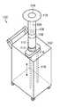
- FIG. 4an isometric drawing of an ultraviolet discharge lamp apparatus having a vertically positioned discharge lamp
- FIG. 5depicts an alternative configuration of a discharge lamp assembly for the ultraviolet discharge lamp apparatus depicted in FIG. 4 ;
- FIG. 6depicts an alternative configuration of an optical filter for the ultraviolet discharge lamp apparatus depicted in FIG. 4 ;
- FIG. 7depicts another alternative configuration of an optical filter for the ultraviolet discharge lamp apparatus depicted in FIG. 4 ;
- FIG. 8depicts a system including multiple ultraviolet discharge lamp apparatuses.
- FIGS. 1-3exemplary configurations of apparatuses are shown in FIGS. 1-3 having a discharge lamp arranged lengthwise parallel to a plane of the apparatus at which the lamp is supported (hereinafter referred to as a “horizontally positioned lamp”).
- FIGS. 4-7exemplary configurations of apparatuses are shown in FIGS. 4-7 having a discharge lamp arranged lengthwise perpendicular to a plane of the apparatus at which the lamp is supported (hereinafter referred to as a “vertically positioned lamp”).
- FIG. 8a system having two discharge lamp apparatuses is shown in FIG. 8 .
- Each of the apparatuses described hereinincludes a discharge lamp configured to generate ultraviolet light and, thus, the apparatuses described herein are sometimes referred to as “ultraviolet discharge lamp apparatuses.”
- the discharge lamp of an apparatusmay be further configured to generate other ranges of light, but such configurations will not deter from the reference of the apparatuses described herein as “ultraviolet discharge lamp apparatuses.”
- the apparatuses described hereinare absent of optics for producing a laser from light emitted from a discharge lamp and, accordingly, may be referred to herein as non-laser apparatuses in some embodiments.
- the apparatuses described hereinare configured to propagate light emitted from the discharge lamp in a non-laser fashion.
- the apparatuses described hereinare configured to expose areas and rooms as well as objects as a whole to ultraviolet light and, thus, are specifically configured to distribute light in a spacious manner rather than producing a narrow beam of limited diffraction as generated by lasers.
- discharge lamprefers to a lamp that generates light by means of an internal electrical discharge between electrodes in a gas.
- the termencompasses gas-discharge lamps, which generate light by sending an electrical discharge through an ionized gas (i.e., a plasma).
- the termalso encompasses surface-discharge lamps, which generate light by sending an electrical discharge along a surface of a dielectric substrate in the presence of a gas, producing a plasma along the substrate's surface.
- the discharge lampswhich may be considered for the apparatuses described herein include gas-discharge lamps as well as surface-discharge lamps. Discharge lamps may be further characterized by the type of gas/es employed and the pressure at which they are operated.
- the discharge lamps which may be considered for the apparatuses described hereinmay include those of low pressure, medium pressure and high intensity.
- the gas/es employedmay include helium, neon, argon, krypton, xenon, nitrogen, oxygen, hydrogen, water vapor, carbon dioxide, mercury vapor, sodium vapor and any combination thereof.
- the discharge lamps considered for the apparatuses described hereinmay be of any size and shape, depending on the design specifications of the apparatuses.
- the discharge lamps considered for the apparatuses described hereinmay include those which generate continuous light and those which generate light in short durations, the latter of which are referred to herein as flashtubes or flashlamps. Flashtubes or flashlamps that are used to supply recurrent pulses of light are referred to herein as pulsed light sources.
- a commonly used gas-discharge lamp used to produce continuous lightis a mercury-vapor lamp, which may be considered for some of the apparatuses described herein. It emits a strong peak of light at 253.7 nm, which is considered particularly applicable for germicidal disinfection and, thus, is commonly referenced for ultraviolet germicidal irradiation (UVGI).
- a commonly used flashlamp which may be considered for the apparatuses described hereinis a xenon flashtube. In contrast to a mercury-vapor lamp, a xenon flashtube generates a broad spectrum of light from ultraviolet to infrared and, thus, provides ultraviolet light in the entire spectrum known to the germicidal (i.e., between approximately 200 nm and approximately 320 nm).
- a xenon flashtubecan provide relatively sufficient intensity in the spectrum which is known to be optimally germicidal (i.e., between approximately 260 nm and approximately 265 nm). Moreover, a xenon flashtube generates an extreme amount of heat, which can further contribute to the deactivation and killing of microorganisms.
- a surface-discharge lampmay be considered for some of the apparatuses described herein as noted above. Similar to a xenon flashtube, a surface-discharge lamp produces ultraviolet light in the entire spectrum known to the germicidal (i.e., between approximately 200 nm and approximately 320 nm). In contrast, however, surface-discharge lamps operate at higher energy levels per pulse and, thus, greater UV efficiency, as well as offer longer lamp life as compared to xenon flashtubes. It is noted that the aforementioned descriptions and comparisons of a mercury-vapor lamp, a xenon flashlamp, and a surface discharge lamp in no way restrict the apparatuses described herein to include such lamps. Rather, the aforementioned descriptions and comparisons are merely provided to offer factors which one skilled in the art may contemplate when selecting a discharge lamp for an ultraviolet discharge lamp apparatus, particularly depending on the objective and application of the apparatus.
- the apparatuses described hereinare configured to distribute ultraviolet light in a spacious manner such that objects as whole and/or areas/rooms may be treated.
- the apparatuses described hereinare not configured to produce a narrow beam of light for a specific small target as may be used for laser applications.
- the apparatuses described hereinmay be particularly applicable for disinfecting, decontaminating and/or sterilizing objects as a whole as well as areas and/or rooms.
- the apparatuses described hereinmay be used for disinfecting hospital rooms or may be used in agricultural operations, including those which are used to breed and/or farm animals.
- the apparatuses described hereinmay be used for reducing microorganism growth on plants or sterilizing objects, such as surgical tools, food or pharmaceutical packaging.
- Other applications for the apparatuses described herein which involve spacious exposure to ultraviolet lightmay be polymer curing and medical procedures.
- the apparatuses described hereinmay be particularly directed to room disinfection. More specifically and as set forth in more detail below, some of the features presented for the apparatuses described herein (particularly the inclusion of an optical filter, the inclusion of a reflector system to redirect ultraviolet light propagating from a support structure of the apparatus, the adaptation to move throughout a room during operation, and/or systems including multiple discharge lamp apparatuses) may be especially suitable for room disinfection apparatuses. For this reason, many of the apparatuses described herein and depicted in the drawings are directed to room disinfection apparatuses. Furthermore, for reasons set forth below, many of the apparatuses described herein and depicted in the drawings are specifically directed to floor based freestanding portable room disinfection apparatuses.
- room disinfectionrefers to the cleansing of a bounded area which is suitable for human occupancy so as to deactivate, destroy or prevent the growth of disease-carrying microorganisms in the area.
- the room disinfection apparatuses described hereinmay come in a variety of configurations, including those which are floor based, wall based and ceiling based. However, although room disinfection apparatuses may be disposed within the ceiling of a room or within or against a wall, in many cases it is advantageous to position a room disinfection apparatus away from such structures. In particular, one of the primary factors affecting UV light intensity (and thus the disinfection efficiency of UV) on an object is distance to the object and, thus, in many cases it is advantageous to position a room disinfection apparatus near the center of a room or near objects suspected to be contaminated to minimize distances to objects.
- the apparatuses described hereinmay be configured to distribute light substantially uni-directionally or multi-directionally.
- the phrase “configured to distribute light substantially unidirectionally”may refer to a configuration of an apparatus to propagate a majority of light emitted from a discharge lamp in a single direction with auxiliary light propagated at angles of less than 30 degrees from such a direction. All other distributions of light may be referenced for the phrase “configured to distribute light multi-directionally.”
- Room disinfection apparatuses configured to distribute light substantially unidirectionallymay be those disposed within a wall or a ceiling and/or which have a discharge lamp nested within the confines of the apparatus without an auxiliary optical component system to redirect light propagating away from the apparatus.
- room disinfection apparatuses configured to distribute light multi-directionallymay be those which have a discharge lamp extending out from a structure at which the discharge lamp is supported and/or which have an auxiliary optical component system to redirect light propagating away from the apparatus.
- a roomgenerally includes objects of different sizes and shapes located at varying heights and distances from a given point in the room (giving rise to the number and varying location surfaces to be disinfected)
- an apparatus used for room disinfectionit is sometimes advantageous for an apparatus used for room disinfection to be configured to distribute ultraviolet light in many directions (i.e., multi-directionally).
- a room disinfection apparatusconfigured such that at least some ultraviolet light generated by a discharge lamp is propagated to a region which encircles an exterior surface of the apparatus and further such that the ultraviolet light propagated to the encircling region during an operation of the apparatus collectively occupies the entirety of the encircling region.
- a configurationprovides distinction from room disinfection apparatuses disposed in ceilings or walls and is described in more detail below in reference to some of the apparatuses depicted in the drawings.
- FIG. 1an exemplary configuration of an ultraviolet discharge lamp apparatus having a horizontally positioned lamp is provided.
- apparatus 20is shown having discharge lamp 22 disposed within support structure 24 and specifically arranged lengthwise parallel to a plane of apparatus 20 at which discharge lamp 22 is supported (i.e., arranged parallel to an upper surface of support structure 24 ).
- the apparatuses described hereinare not restricted to embodiments in which a discharge lamp is arranged in a “horizontal position.” Rather, the apparatuses described herein may include discharge lamps arranged at any angle relative to the surface plane of the support structure at which the discharge lamp is supported.
- the apparatuses described hereinare not limited to embodiments in which a discharge lamp is arranged in proximity to an upper surface of an apparatus.
- the apparatuses described hereinmay have discharge lamps arranged in proximity to any exterior surface of an apparatus, including sidewalls and bottom surfaces. Horizontally positioned and vertically positioned lamps arranged in proximity to upper surfaces of support structures are discussed herein in particularity since these were the configurations used to refine some of the novel features of the apparatuses disclosed herein. However, such disclosure should not be construed to necessarily limit the arrangement of discharge lamps in the apparatuses described herein.
- the apparatuses described hereinare not restricted to embodiments in which a discharge lamp is nested within the confines of a support structure as depicted in FIG. 1 . Rather, apparatuses may alternatively have a discharge lamp which is arranged at least partially exterior to a support structure, such as described for the exemplary embodiments depicted in FIGS. 3-7 .
- apparatus 20may, in some embodiments, include CPU 32 to carry out applicable program instructions.
- apparatus 20may optionally include user interface 34 to offer a means for a user to activate operation, and possibly particular operation modes, of apparatus 20 as well as offer a means for a user to access data collected from the apparatus.
- Room occupancy sensor 36is an optional safety mechanism, which may generally be configured to determine whether people are present in the room, such as by motion detection or photo recognition.
- Other optional features shown in apparatus 20include wheels 38 and handle 39 to affect portability for the apparatus, but may be omitted depending on the design specifications of the apparatus.
- apparatus 20may include optical filter 40 , cooling system 44 and reflector system 60 .
- optical filter 40cooling system 44 and reflector system 60 .
- the configuration of optical filters, cooling systems and reflector systems as well as the placement of discharge lampsmay vary among the apparatuses described herein.
- alternative embodiments for one or more of such featuresare described in reference to FIGS. 2-7 relative to the configurations shown and described in reference to FIG. 1 .
- Each of such embodimentsinclude a support structure and accompanying components as described for FIG. 1 , specifically in reference to support structure 22 , power circuit 26 , pulse regulator circuit 30 , CPU 32 , user interface 34 , room occupancy sensor 36 , wheels 38 and handle 39 .
- Such featureshave not been depicted in FIGS. 2-7 for simplicity purposes as well as to emphasize the differing configurations of the depicted optical filters and reflector systems as well as the placement of discharge lamps.
- each of the apparatuses described hereinincludes a discharge lamp configured to generate ultraviolet light.
- a discharge lamp of an apparatusmay be further configured to generate other ranges of light, such as but not limited to visible light.
- it may be advantageous to attenuate the visible lightparticularly if (but not necessarily so limited) the generated visible light is very bright and/or distracting.
- xenon flashlampsgenerate pulses of a broad spectrum of light similar to the spectrum of sunlight, but the intensity of the visible light is up to 20,000 times higher than that of sunlight.
- the apparatuses described hereinmay, in some embodiments, include an optical filter configured to attenuate visible light.
- the apparatuses described hereinmay include an optical filter configured to attenuate light in a majority portion of the visible light spectrum, greater than 75% of the visible light spectrum, or the entire visible light spectrum. In other embodiments, however, the optical filter may be configured to attenuate light in less than a majority portion of the visible light spectrum. In any case, the optical filter may be configured to attenuate a majority amount of light in a given portion of the visible light spectrum and, in some cases, greater than 75% or all light in a given portion of the visible light spectrum.
- the optical filtermust pass ultraviolet light in addition to attenuating visible light.
- the optical filtermay be visible light band-stop filter. In other embodiments, however, the optical filter may be an ultraviolet band-pass filter. In either case, the optical filter may be configured to pass a majority amount of light in a given portion of the ultraviolet light spectrum and, in some embodiments, greater than 75% or all light in a given portion of the ultraviolet light spectrum. In some cases, the given portion of the ultraviolet light spectrum may be a majority portion of the ultraviolet light spectrum, greater than 75% of the ultraviolet light spectrum, or the entire ultraviolet light spectrum.
- the given portion of the ultraviolet light spectrummay be less than a majority portion of the ultraviolet light spectrum.
- the optical filtermay be specifically configured to pass light in a specific portion of the ultraviolet spectrum. For example, in cases in which the apparatus is used for disinfection, decontamination, or sterilization purposes, the optical filter may be configured to pass light in a majority portion, greater than 75%, or the entire portion of the germicidal UV spectrum (i.e., approximately 200-320 nm). In addition or alternatively, the optical filter may be configured to pass light in a majority portion, greater than 75%, or the entire portion of the ultraviolet light spectrum known to be optimally germicidal (i.e., approximately 260-265 nm).
- An exemplary optical filter glass material which may be used as an optical filter for the apparatuses described hereinis Schott UG5 Glass Filter which is available from SCHOTT North America, Inc. of Elmsford, N.Y. Schott UG5 Glass Filter attenuates a majority portion of the visible light spectrum while allowing approximately 85% of ultraviolet light in a range of approximately 260 nm to approximately 265 nm to pass.
- Other optical filter glass materials with similar or differing characteristicsmay be used as well, depending on the design specifications of an apparatus.
- an optical filter considered for the apparatuses described hereinmay be a film having any of the optical characteristics described above. In such embodiments, the film may be disposed on an optically transparent material, such as quartz.
- an optical filter considered for the apparatuses described hereinmay be a combination of an optical filter glass material and a film disposed thereon, each of which is configured to attenuate visible light.
- optical filter glass material used hereinrefers to a material designed to influence the spectral transmission of light by either blocking or attenuating specific wavelength spectrums.
- optically transparent used hereinrefers to a material which allows light to pass through without substantial blockage or attenuation of a specific wavelength spectrum. Quartz is a well known optically transparent material.
- film as used hereinrefers to a thin layer of a substance and is inclusive to the term coating which refers to a layer of a substance spread over a surface. Films considered for the optical filters described herein may be in solid or semi-solid form and, thus, are inclusive to solid substances and gels.
- an optical filter considered for the apparatuses described hereinmay include a rate of solarization that is approximately a whole number multiple of a degradation rate of the discharge lamp.
- the discharge lampmay have a rate of degradation that is an approximate factor of a rate of solarization of the optical filter.
- the term factor in such a characterization of the optical filterrefers to the mathematical definition of the term, specifically referring to a number that divides another number evenly, i.e., with no remainder.
- the rate of solarization of an optical filtermay be approximately any whole number multiple of a degradation rate of the discharge lamp including one and, thus, in some embodiments, a rate of solarization of an optical filter may be similar or the same as the rate of degradation of a discharge lamp.
- discharge lampsare warrantied to a number of uses (i.e., a particular number of triggers to generate a plasma), which is determined in accordance with the expected degradation of one or more of its components.
- pulsed light sourcesare often warrantied to particular number of pulses.
- a use countcould be used to characterize a degradation rate of a discharge lamp by multiplying the amount of ultraviolet light to be emitted during each operation times the number of triggers the discharge lamp is warrantied to be used. In this manner, a degradation rate may be computed which can be correlated to a solarization rate of an optical filter.
- the componentsmay be advantageously replaced at the same time and, thus, downtime of the apparatus may be reduced relative to embodiments in which the components are replaced based on their individual merits.
- the monitoring processmay be simplified in that light from only one component needs to be measured.
- optical filters in the embodiments described in reference to FIGS. 1-7may have the optical filter characteristics set forth above. The characteristics are not reiterated for each embodiment for the sake of brevity.
- an optical filtermay be especially suitable for a room disinfection apparatus. This is because room disinfection apparatuses are generally configured to distribute light into the environment of the apparatus and, thus, do not include a housing to contain the light. It is noted that although the inclusion of an optical filter may be beneficial in some of the apparatuses described herein, it is not necessarily a requirement and, thus may be omitted in some embodiments.
- a reflector systemconfigured to redirect ultraviolet light propagating away from a support structure of an apparatus.
- the reflector systems considered for the apparatuses described hereinmay be used to increase the size of an area exposed to ultraviolet light by the apparatus, decrease the distance ultraviolet light is propagated to target objects or areas, and/or improve the incidence angle of ultraviolet light on target objects or areas.
- FIGS. 1-7Several different exemplary configurations and arrangements of reflector systems configured to accomplish one or more of such objectives are described in more detail below and are shown in FIGS. 1-7 . In particular, apparatuses having a repositionable reflector are described.
- apparatuses having a reflector system which is configured to redirect ultraviolet light propagating away from a support structure of the apparatus to encircle an exterior surface of the apparatusare described. As noted above, such a configuration may be particularly applicable for room disinfection apparatuses.
- apparatuseswhich have a reflector system configured to redirect ultraviolet light propagating away from a support structure of an apparatus to a region exterior to the apparatus and which is between approximately 2 feet and approximately 4 feet from a floor of a room in which the apparatus is arranged.
- the region between approximately 2 feet and approximately 4 feet from a floor of a roomis considered a “high touch” region of a room since objects of frequent use are generally placed in such a region.
- objects typically found in a high touch zone of a roominclude but are not limited to desktops, keyboards, telephones, chairs, door and cabinet handles, light switches and sinks.
- objects in high touch zones of hospital roomsadditionally or alternatively include beds, bedside tables, tray tables and intravenous stands.
- the high touch zoneDue to such a region being considered a high touch zone, it is generally considered the area of highest probability to come in contact with germs and some studies indicate that the high touch zone may be the area having the highest concentration of germs. For such reasons, it may be advantageous to direct at least some ultraviolet light to a region which is between approximately 2 feet and approximately 4 feet from a floor of a room. The inclusion of a reflector system as described herein may be used to attain such an objective.
- the reflector systems described hereinmay be especially suitable for a room disinfection apparatus.
- room disinfection apparatusesare generally configured to distribute light into the environment of the apparatus and, thus, do not include a housing to contain and reflect the light.
- many of the apparatuses described herein and depicted in the drawingsare directed to floor based room disinfection apparatuses wherein the discharge lamp is arranged to propagate light above an upper surface of the support structure of the apparatus.
- such emphasized disclosureshould not, however, be construed to necessarily limit the configurations of the apparatuses described herein.
- the reflector system of the apparatusmay include a reflector coupled to an uppermost portion of the sidewall surface and/or a reflector coupled to a lowermost portion of the sidewall surface such that ultraviolet light is reflected downward or upward to a concentrated area.
- the reflector system of the apparatusmay include a reflector below the discharge lamp.
- a reflector system considered for the apparatuses described hereinmay include one or more reflectors, which may be of any size or shape and may be arranged at any position within an apparatus to achieve the desired redirection of light.
- the material of the reflector/smay be any found suitable for the desired redirection of light.
- An exemplary reflector material found suitable for many of the apparatus configurations described hereinis 4300UP Miro-UV available from ALANOD Aluminium-Veredlung GmbH & Co. KG.
- Another exemplary reflector material found suitable for many of the apparatus configurations described hereinis GORE® DRP® Diffuse Reflector Material available from W. L. Gore & Associates, Inc.
- each of the embodiments of the reflection systems described in reference to FIGS. 1-7may have the characteristics of the reflection systems set forth above. The characteristics are not reiterated for each embodiment the sake of brevity.
- an optical filterin the apparatuses described herein, although the inclusion of a reflector system may be beneficial in some apparatuses, it is not necessarily a requirement and, thus, may be omitted in some embodiments.
- the features of an optical filter and a reflector systemare not mutually exclusive or mutually inclusive for an apparatus and, thus, an apparatus may include one or both features.
- apparatus 20includes optical filter 40 configured to attenuate visible light emitted from discharge lamp 22 .
- the configuration of optical filter 40 to attenuate visible light emitted from discharge lamp 22 in FIG. 1specifically pertains to the optical characteristics of the filter to attenuate visible light as well as the placement of the optical filter above and in alignment with discharge lamp 22 .
- optical filter 40may be arranged flush with the upper surface of support structure 24 between the sidewalls of cup portion 42 such that optical filter 40 comprises a wall of an encasement enclosing discharge lamp 22 .
- the apparatuses described hereininclude a cooling system for regulating the temperature of the discharge lamp and encasing the lamp within an enclosure offers an efficient manner to achieve a desired temperature.
- the use of optical filter 40 as a wall of an encasement of discharge bulb 22may simplify the incorporation of the optical filter into apparatus 20 and, thus, may be beneficial in some design aspects. However, in some embodiments, it may be beneficial to have optical filter 40 distinct from an encasement of discharge lamp 22 . For example, in some cases, it may be advantageous to be able to arrange an optical filter in and out of alignment with a discharge lamp, depending on the desired operation of the apparatus. Such a configuration is described in more detail below and exemplary variations of apparatus 20 to accommodate such a configuration are shown in FIGS. 2 a - 2 c.
- Cooling system 44 shown in FIG. 1is a forced air system including air inlet 46 , air intake duct 48 , fan 50 , temperature sensor 52 , air duct 54 and air outlet 56 .
- air inlet 46 , air intake duct 48 , air duct 54 and air outlet 56may include air filters.
- air duct 54 and/or air outlet 56may additionally or alternatively include an ozone filter. In other cases, however, an ozone filter may be omitted from the apparatus.
- Ozonemay generally be created as a byproduct from the use of discharge lamp 22 , specifically if the lamp generates ultraviolet light of wavelengths shorter than approximately 240 nm since such a spectrum of UV light causes oxygen atoms of oxygen molecules to dissociate, starting the ozone generation process.
- Ozoneis a known health and air quality hazard and, thus, the release of it by devices is regulated by the Environmental Protection Agency (EPA). It is also known that ozone is an effective germicidal agent and, thus, if the amount of ozone to be generated by a discharge lamp is lower than the EPA exposure limits for ozone, it may be beneficial to exclude an ozone filter from apparatuses including such a discharge lamp.
- EPAEnvironmental Protection Agency
- a cooling systemmay be configured with an air outlet on the lower portion of a sidewall of support structure 24 or on the bottom surface of support structure 24 .
- Benefits of such alternative configurationsinclude increased capacity for an ozone filter as well as reduced disturbance to the environment, particularly when an air outlet is positioned on the bottom surface of support structure 24 .
- the apparatuses described hereinmay include a cooling system for the rest of the components within support structure 24 .
- the support structure cooling systemmay be integrated with cooling system 44 for discharge lamp 22 . In other embodiments, however, the two cooling systems may be distinct.
- apparatus 20may include reflector system 60 .
- reflector system 60is configured to redirect ultraviolet light propagating away from support structure 24 .
- the configuration of reflector system 60 to achieve such an objectiveinvolves the placement, shape, size and angle of reflector 62 .
- discharge lamp 22is arranged in apparatus 20 to propagate light above an upper surface of support structure 24 , and, thus, reflector 62 is arranged above discharge lamp 22 to redirect the propagating ultraviolet light.
- the redirection of the ultraviolet lightreduces the distance ultraviolet light travels to objects adjacent to the apparatus, including underside surfaces of objects as well as top and sidewall surfaces of objects.
- the redirection of ultraviolet light via reflector 62averts travel to surfaces above the apparatus (e.g., the ceiling of the room in which the apparatus is arranged) to get reflected back to objects adjacent to the apparatus. Averting travel to surfaces above the apparatus also shortens the distance ultraviolet light needs to travel to be incident on the underside of objects (such as by reflection from the floor of a room in which an apparatus is arranged).
- reflection system 60may be configured to optimize the incident angle at which ultraviolet light is directed to object surfaces.
- reflector 62may be designed with a specific size and/or shape and/or may be repositionable such that an optimum incident angle upon an object may be obtained. Exemplary configurations in which reflector 62 is repositionable are discussed in more detail below.
- reflector system 60may, in some embodiments, include one or more additional reflectors (i.e., in addition to reflector 62 ).
- reflector system 60may include a reflector coupled to a sidewall of support structure 24 , which is configured to redirect ultraviolet light received from reflector 62 .
- Additional reflectormay be beneficial for directing ultraviolet light to undersides of objects within a room. Additional reflectors may be used as well or alternatively and may generally be designed (i.e., size, shape and placement) to achieve any one of the objectives noted above for reflector system 60 in conjunction with reflector 62 .
- reflector system 60may be specifically configured to redirect ultraviolet light propagating away from support structure 24 to a region which is between approximately 2 feet and approximately 4 feet from a floor of a room in which apparatus 20 is arranged. In particular, as set forth above, it may be advantageous to redirect ultraviolet light to such a region since it is a high touch zone. In some cases, reflector system 60 may be additionally or alternatively configured to redirect ultraviolet light propagating away from support structure 24 to a region which encircles an exterior surface of the apparatus. For instance, reflector 62 may be of a shape and size such that ultraviolet light is redirected to a region encircling support structure 24 . Alternatively, reflector 62 may be of a shape and size such that ultraviolet light is redirected to a region encircling reflector system 60 . In either case, a conical shape for reflector 62 may be particularly suitable to achieve such redirection.
- encirclerefers to the formation of a continuous circle around an object.
- the termis not restricted to embodiments of surrounding an entirety of an object or even a major portion of an object.
- the phrasing that the apparatuses described hereinmay be configured such that ultraviolet light encircles an exterior surface of an apparatus refers to the formation of a continuous ring of ultraviolet light around at least some exterior portion of the apparatus.
- the phrasing that the apparatuses described hereinmay be configured such that ultraviolet light propagated to a region encircling an apparatus during an operation of the apparatus collectively occupies the entirety of the encircling region refers to each part of a continuous ring region around an apparatus being exposed to ultraviolet light at some time during the operation of the apparatus.
- apparatus 20may, in some embodiments, include another reflector system arranged within support structure 24 which is configured to redirect light emitted from discharge lamp 22 in the direction of light propagation away from the support structure.
- apparatus 20may include a reflection system which is configured to redirect light emitted from the side and bottom surfaces of discharge lamp 22 in the same direction as the light emitted from the top surfaces of discharge lamp 22 .
- An example of such a reflection systemmay involve the floor and/or sidewalls of cup portion 42 having a reflective material.
- Other configurations of reflection systemsmay be considered for the apparatuses described herein.
- reflector system 60may include support beams 64 and 66 to suspend reflector 62 .
- Such a cantilever support structureis merely an example and various other support structures may be considered for reflector 62 .
- reflector system 60may, in some cases, include through holes such that some light propagated toward reflector system 60 may pass through to regions above reflector system 60 .
- An example of an embodimentis shown in FIG. 1 with support beam 66 including through holes 68 .
- reflector 62may include through holes for such a purpose.
- reflector system 60may be void of such through holes.
- the size of reflector system 60 and, more specifically, the size of reflector 62may vary among apparatuses.
- the areal dimensions of reflector 62may be the same or larger than the areal dimensions of the encasement in which discharge lamp 22 is contained. In this manner, nearly all the light propagating from support structure 24 will be directed to reflector 62 .
- the areal dimensions of reflector 62may be smaller than the areal dimensions of the encasement in which discharge lamp 22 is contained. In such cases, some light propagating from support structure 24 may be directed beyond reflector 62 .
- reflector system 60may, in some cases, be configured to move reflector 62 in the horizontal and/or vertical direction as shown by the double-arrowed lines in FIG. 1 . In this manner, reflector 62 may be repositionable reflector. In some embodiments, reflector 62 may be moved between operations of apparatus 20 and, as such, reflector system 60 may, in some cases, include a means for securing the repositionable reflector at different positions within apparatus 20 . In other embodiments, reflector system 60 may include a means for moving reflector 62 while apparatus 20 is in operation. The movement of reflector 62 may be continuous or periodic while apparatus 20 is in operation and, thus, reflector 62 may be moved while discharge lamp 22 is emitting light in some cases.
- the reference of apparatus 20 being in operationrefers to when the components of the apparatus have been activated to operate discharge lamp 22 and specifically the operations by which to generate a radiating plasma within the discharge lamp.
- discharge lamp 22may, in some embodiments, be configured to generate continuous light once the lamp is triggered and, as such, the reference of apparatus 20 being in operation in such cases refers to the time used to trigger the lamp as well as the time of continuous light emission.
- a flashlamp or a pulsed light sourcemay be used for discharge lamp 22 and, in such cases, the reference of apparatus 20 being in operation refers to the times in which light is emitted from the lamp as well as times in between the light flashing.
- a means for moving reflector 62 and sometimes securing reflector 62 at different positions within apparatus 20may, in some embodiments, include linear actuator/s for beam 64 and/or beam 66 as well as program instructions processed by CPU 32 to affect the movement of the linear actuator/s and the timing thereof.
- apparatus 20may be configured such that reflector 62 may be moved manually.
- An exemplary means for securing reflector 62 at different positions within apparatus 20 in such casesmay include notches along beam 64 and/or beam 66 and a receiving protrusion on reflector 62 or vice versa.
- Other various means for moving reflector 62 and/or securing reflector 62 at different positions within apparatus 20may be considered as well and, thus, the apparatuses are not limited to the examples noted above.
- reflector 62may be detachable from apparatus 20 in some cases to affect its movement relative to discharge lamp 22 and/or for ease of storage or portability of apparatus 20 .
- the movement of reflector 62may be based on characteristics of a room in which apparatus 20 is arranged.
- it may be advantageous to analyze the characteristics of a roomsuch as but not limited to determining the size of the room and/or determining the number, size and/or distances of objects within the room.
- Such informationmay be worthwhile to determine a number of operational parameters for apparatus 20 , such as but not limited to the placement of reflector 62 and/or the movement characteristics of reflector 62 . For example, if a relatively high number of objects within a room are in the same general area, it may be beneficial to position reflector 62 to direct more light to that area as compared to other areas in the room.
- apparatus 20may include system 70 for collecting data regarding characteristics of a room in which the apparatus is arranged. Any system known in the art for analyzing characteristics of a room may be used. Examples include spatial sensors and/or photo recognition systems. As shown in FIG. 1 , system 70 may, in some embodiments, be operationally coupled to CPU 32 . In such cases, CPU 32 may be configured to retrieve data from system 70 and determine a position of reflector 62 based on the data. In some embodiments, the determined position may be relayed via user interface 34 such that a user of apparatus 20 may be informed to move reflector 62 to such a position. In other cases, CPU 32 may be configured to send a command in accordance with the determined position to a means within apparatus 20 for automatically moving reflector 62 .
- system 70may be additionally or alternatively used to measure doses of ultraviolet light received at an object or spot in a room in which apparatus 20 is arranged.
- measuring the dose of ultraviolet light received at an object or spot in a roommay aid in optimizing the placement of reflector 62 .
- one of the primary factors affecting UV light intensity on an objectis distance to the object.
- Another primary factoris the angle of incidence of the light. In light thereof, if doses of ultraviolet light received at an object or spot in a room can be measured, such measurements can be used to move reflector 62 such as to optimize the angle of incidence on the object or spot.
- CPU 32may be configured to retrieve measurements from system 70 , determine a position of reflector 62 based on the measurements, and either relay the determined position to user interface 34 and/or send a command in accordance with the determined position to a means within apparatus 20 for automatically moving reflector 62 .
- any system known in the art for measuring ultraviolet light dosesmay be used for system 70 . Examples include ultraviolet dosimeters and radiometers.
- the apparatuses considered hereinmay, in some embodiments, include a sensor system configured to monitor parameter/s associated with the operation of the discharge lamp and, if applicable, parameter/s associated with the transmittance of the optical filter.
- a sensor systemmay be beneficial for determining when to replace the discharge lamp and, if applicable, the optical filter as well as monitoring the efficiency of the UV light emitted from the apparatus since it relates to UV intensity and dose.
- the parameter/s associated with the transmittance of an optical filtermay be ultraviolet light dose or ultraviolet light intensity.
- a sensor systemwhen a sensor system is to be used to monitor parameter/s associated with both the operation of a discharge lamp and the transmittance of an optical filter, the sensor system may be configured to monitor the same parameters or different parameters regarding the two components.
- a sensor systemmay include a single sensor configured to measure parameter/s associated with a discharge lamp and an optical filter. In other embodiments, however, a sensor system may include distinct sensors for measuring respective parameters of a discharge lamp and an optical filter.
- An exemplary sensor system for apparatus 20 of FIG. 1includes sensor 72 arranged on the underside of reflector system 60 and sensor 74 arranged in the encasement comprising discharge lamp 22 .
- sensor 74may be used to monitor a parameter associated with the operation of discharge lamp 22 and, more specifically, may be used to monitor light emitted from discharge lamp 22 prior to passing through optical filter 40 .
- FIG. 1illustrates sensor 74 disposed on a sidewall surface of cup portion 42 , but sensor 74 may be arranged at any location within the encasement of discharge lamp 22 . In other embodiments, sensor 74 may be omitted from apparatus 20 .
- sensor 72may, in some embodiments, be configured to monitor parameters associated with the operation of discharge lamp 22 (such as by pulse count) and, thus, sensor 74 may not be needed.
- sensor 72may be used to monitor a parameter associated with the transmittance of optical filter 40 and, thus, may be arranged at any location on apparatus 20 or nearby apparatus 20 to receive light passed through optical filter 40 .
- FIG. 1shows sensor 72 arranged on the underside of reflector system 60 , but such a placement is exemplary.
- Example embodimentsinclude those in which an apparatus will be used in various rooms, some with windows and others with no windows.
- an optical filterto transmit ultraviolet radiation will decrease in relation to its time of exposure to UV radiation due to solarization.
- having the ability to arrange an optical filter out of alignment with a discharge lampmay offer a manner in which to extend the life of an optical filter for a given apparatus.
- FIGS. 2 a - 2 cExemplary variations of apparatus 20 which are configured such that an optical filter may be arranged in an out of alignment with discharge lamp 22 are shown in FIGS. 2 a - 2 c .
- FIGS. 2 a - 2 cillustrate variations to the placement of optical filter 40 relative to its placement in FIG. 1 as being part of the encasement of discharge lamp 22 .
- FIGS. 2 a - 2 cmerely set forth examples of configurations for accommodating an optical filter in an out of alignment with a discharge lamp, but such exemplary disclosures and depictions should not be construed to limit the configurations of apparatuses described herein for such an objective.
- FIGS. 2 a - 2 care described as variations to apparatus 20 in FIG.
- FIGS. 2 a - 2 conly depict a fraction of an apparatus in the interest to simplify the drawings.
- FIGS. 2 a - 2 conly depict the placement of optical filter 40 relative to the encasement of discharge lamp 22 within support structure 24 .
- FIGS. 2 a - 2 cfeatures depicted in FIGS. 2 a - 2 c with the same configurations as described in reference to FIG. 1 (i.e., discharge lamp 22 , support structure 24 , optical filter 40 and cup portion 42 ) are denoted with the same reference numbers and the descriptions of such features are not reiterated for the sake of brevity. Since the embodiments of FIGS.
- FIGS. 2 a - 2 cdo not have optical filter 40 as part of the encasement of discharge lamp 22
- each of FIGS. 2 a - 2 cinclude a new feature relative to FIG. 1 , specifically encasement topper 82 .
- encasement topper 82may be of an optically transparent material, such as but not limited to quartz.
- variation 80 to apparatus 20may include optical filter 40 arranged upon encasement topper 82 .
- optical filter 40may, in some embodiments, simply be placed on top of support structure 24 (i.e., the portion of support structure 24 comprising encasement topper 82 ) without a means of securing optical filter 40 to the support structure.
- variation 80may include a means to affix optical filter 40 to support structure 24 . In either case, placement of optical filter 40 upon encasement topper 82 may be manual or may be automated.
- FIG. 2 billustrates variation 84 of apparatus 20 slightly modified relative to variation 80 in FIG. 2 a . In particular, FIG.
- FIG. 2 billustrates the inclusion of hinge 86 mounted to one side of optical filter 40 .
- optical filter 40may be arranged upon encasement topper 82 and may be removed from such a position without detachment from the apparatus.
- Hinge 86may be configured to pivot optical filter 40 any angle between 90 and 180 degrees relative to the position of optical filter 40 shown in FIG. 2 b .
- optical filter 40may be put in any position between an upright position and a position on support structure 24 opposing discharge lamp 22 when moved from the position above the discharge lamp. Movement of optical filter 40 in such embodiments may be manual or may be automated.
- FIG. 2 cwhich has optical filter 40 arranged upon a slider for moving the optical filter in and out of alignment with discharge lamp 22 along the upper surface of support structure 24 , as is indicated by the horizontal double arrow. The movement of optical filter 40 on the slider may be manual or automated.
- apparatus 20may be configured such that optical filter 40 is protected from exposure to ultraviolet light when not in alignment with discharge lamp 22 .
- apparatus 20may, in some embodiments, include a compartment in which optical filter 40 may be placed when it is removed from and/or repositioned in the apparatus.
- apparatus 20may include a component to cover optical filter 40 when it is taken out of alignment with discharge lamp 22 .
- apparatuses 2 a - 2 cmay be automated and, thus, not only may the apparatuses disclosed herein be configured to accommodate an optical filter in and out of alignment with a discharge lamp, the apparatuses may, in some embodiments, include a means for automatically moving the optical filter in and out of alignment with the discharge lamp. Such a means may include any mechanism/s known in the art for moving objects.
- the determination of whether to move the optical filter and/or the timing to move the optical filtermay be determined by a user of apparatus 20 .
- apparatus 20may include program instructions which are executable by CPU 32 such that the determination of whether to move the optical filter and/or the timing to move the optical filter may be automated.
- apparatus 20may include a system, such as system 70 , for collecting data regarding characteristics of a room in which the apparatus 20 is arranged and, more specifically, for determining whether there is a window in the room.
- system 70any system known in the art for determining whether there is a window in the room may be used for system 70 in such cases, such as but not limited to reflection sensors.
- CPU 32may be configured to retrieve data from system 70 , determine a position of optical filter 40 based on the data, and either relay the determined position to user interface 34 and/or send a command in accordance with the determined position to a means within apparatus 20 for automatically moving optical filter 40 .
- optical filter 40may be arranged in alignment with discharge lamp 22 prior to operating the discharge lamp to produce light. Conversely, in embodiments in which a window is not detected in a room in which apparatus 20 is arranged, optical filter 40 may be arranged out of alignment with discharge lamp 22 prior to operating the discharge lamp to produce light. It is noted that the optional configurations of system 70 and CPU 32 to affect movement of optical filter 40 may be in addition or alternative to the configurations noted above for affecting movement of reflector 62 .
- FIG. 2 cillustrates an optional feature for apparatus 20 in conjunction with including a slider for optical filter 40 , specifically the inclusion of thermal rejuvenation chamber 90 adjacent to support structure 24 .
- the ability of an optical filter to transmit ultraviolet radiationwill decrease in relation to its time of exposure to UV radiation due to solarization. In some cases, however, the solarization effects may be reversed if the optical filter is heated at high temperatures, such as on the order of 500° C.
- the processmay be done independent of apparatus 20 , it may be advantageous in some embodiments to incorporate the process into apparatus 20 to reduce downtime of the apparatus and/or such that a replacement optical filter does not need to be on hand while optical filter 40 is being rejuvenated.
- thermal rejuvenation chamber 90be a distinct chamber from support structure 24 .
- thermal rejuvenation chamber 90it would be advantageous for thermal rejuvenation chamber 90 to be configured to not only withstand, but substantially contain the heat generated therein to prevent heat degradation/damage of components within support structure 24 .
- apparatus 20may, in some embodiments, be configured to move optical filter 40 into thermal rejuvenation chamber 90 . In other embodiments, it may be done manually. In either case, the movement of optical filter 40 into thermal rejuvenation chamber 90 may, in some embodiments, be dependent on measurements taken regarding the transmittance of optical filter 40 . In particular, information collected from sensor 72 regarding the transmittance of optical filter 40 may be used to determine when to move the optical filter into thermal rejuvenation chamber 90 . Although the inclusion of a thermal rejuvenation chamber may be beneficial in some apparatuses, it is not a requirement and, thus, may be omitted in some embodiments.
- thermal rejuvenation chamber 90 and optical filter 40being on a slider as shown in FIG. 2 c are neither mutually exclusive nor mutually inclusive for an apparatus and, thus, an apparatus may include one or both features.
- any of the apparatuses described herein which include an optical filtermay include a thermal rejuvenation chamber, including those described above in reference to FIGS. 1 , 2 a and 2 b as well as those described below in reference to FIGS. 3-7 .
- apparatuses described hereinare not restricted to embodiments in which a discharge lamp is disposed (i.e., nested) within the confines of a support structure as depicted in FIG. 1 . Rather, apparatuses may alternatively have a discharge lamp which is arranged at least partially exterior to a support structure.
- An exemplary embodiment of a variation to apparatus 20 in which discharge lamp 22 is arranged exterior to support structure 24is shown in FIG. 3 .
- variation 92may include a different optical filter configuration than that shown for apparatus 20 in FIG. 1 , specifically optical filter 94 instead of optical filter 40 .
- optical filter 94is configured to attenuate visible light propagated sideways from discharge lamp to account for discharge lamp 22 being arranged above support structure 24 . Due to such a displacement of discharge lamp 22 , cup portion 42 may, in some embodiments, be omitted from support structure 24 as shown in FIG. 3 . In such cases, variation 92 may, in some embodiments as shown in FIG. 3 , include reflective plane 96 disposed below discharge lamp 22 to redirect light emitted from the bottom of discharge lamp 22 upward.
- the apparatuses described hereinare not restricted to embodiments in which a discharge lamp is arranged in a “horizontal position.” Rather, the apparatuses described herein may include discharge lamps arranged at any angle relative to the surface plane at which the lamp is supported. Examples of apparatuses having discharge lamps arranged in a “vertical position” (i.e., arranged lengthwise perpendicular to a plane of the apparatus at which the lamp is supported) are shown in FIGS. 4-7 . Each of such embodiments include a support structure, a power circuit and accompanying optional components (e.g., pulse regulator circuit, CPU, user interface, sensors, room characteristics system, hinge, slider, thermal rejuvenation chamber) as described for FIG. 1 .
- optional componentse.g., pulse regulator circuit, CPU, user interface, sensors, room characteristics system, hinge, slider, thermal rejuvenation chamber
- apparatus 100having a discharge lamp assembly supported above support structure 102 and arranged lengthwise perpendicular to a plane of support structure 102 .
- the discharge lamp assemblyincludes discharge lamp 104 surrounded by optical filter 106 and vertically disposed between fan 108 and ozone filter 119 .
- the discharge lamp assemblyincludes base 110 and air filter 112 supported at base 114 .
- Optical filter 106may, in some embodiments, be a wall of an encasement enclosing discharge lamp 22 , making up a forced air cooling system for apparatus 100 with fan 108 .
- Apparatus 100further includes reflector 118 affixed to ozone filter 119 at the top of optical filter 106 .
- the characteristics of reflector 118 , discharge lamp 104 and the cooling system of apparatus 100 as well as the optical characteristics of optical filter 106may generally include those described above for all of the apparatuses considered herein and are not reiterated for the sake of brevity. As with the embodiments described above, several of the components included in apparatus 100 may be replaced and/or omitted for other configurations of apparatuses described herein, particularly optical filter 106 , reflector 118 and ozone filter 119 . As such, the compilation and configurations of components depicted in FIG. 4 are not necessarily mutually inclusive.
- apparatus 100may include additional components (i.e., components other than what is depicted in FIG. 4 ).
- apparatus 100may include an optically transparent intermediate barrier arranged between and spaced apart from discharge lamp 104 and optical filter 106 .
- An exemplary material for the intermediate barriermay be quartz, but its composition is not so limited.
- the intermediate barriermay be a wall of an encasement enclosing discharge lamp 104 and, thus, may be vertically disposed between fan 108 and ozone filter 119 and part of the cooling system for apparatus 100 .
- optical filter 106surrounds the intermediate barrier as a distinct glass piece spaced apart from the intermediate barrier and is secured to base 110 , fan 108 , and/or reflector 118 .
- an intermediate barrier between discharge lamp 104 and optical filter 106may be advantageous when it is desirable to have the capability to arrange optical filter 106 in and out of alignment with discharge lamp 104 or when it is desirable to have optical filter 106 move independent of discharge lamp 104 during operation of the apparatus.
- an intermediate barriermay take on the role as being part of an encasement to discharge lamp 104 , allowing movement of optical filter 106 without sacrificing a cooling system for discharge lamp 104 .
- optical filter 106may be secured to base 110 or fan 108 , but may be spaced apart from reflector 118 or vice versa.
- apparatus 100may include an additional component/s coupled to optical filter 106 which is configured to block light, particularly visible light, in the gap between optical filter 106 and base 110 , fan 108 or reflector 118 .
- Exemplary components which may be particularly suitable for such functionmay be a dense collection of bristles.
- apparatus 100may include a cap component spaced above the discharge lamp assembly to allow for air discharge to the side of the apparatus rather than above the apparatus.
- An exemplary configuration of a cap componentis shown in FIG. 5 and described in more detail below.
- An alternative solution to prevent sprinkler systems from being triggered from exhaust of a cooling systemis to lower the flow rate of gas through the lamp assembly if doing so does not cause the discharge lamp to be above its suggested maximum operating temperature.
- decreasing the gas flow ratemay not be desirable in some cases (i.e., even if it does not cause the discharge lamp to exceed is maximum operating temperature) since operating discharge lamps at cooler temperatures generally offers a longer life for the lamp and theoretically generates more ultraviolet light.
- FIG. 5illustrates variation 115 to apparatus 100 having cap component 117 arranged above the lamp discharge assembly of the apparatus and, more specifically, above an outlet of the cooling system within the lamp discharge assembly such that exhaust therefrom may be directed sideways rather than above the apparatus.
- cap component 117may be may be domed to prevent objects from being placed thereon.
- Such a dome configurationis not restricted to embodiments in which an apparatus includes a cap component above a discharge lamp assembly.
- the top of a discharge lamp assemblymay be domed in some cases to prevent objects from being placed thereon.
- the inclusion of cap component 117is not mutually inclusive to embodiments in which ozone filter 119 comprises the entire top portion of the discharge lamp assembly as shown in FIG. 5 .
- any of the apparatuses disclosed hereinmay include a component spaced apart from an outlet of its cooling system to direct exhaust therefrom.
- apparatus 100may, in some embodiments, include linear actuators 116 coupled to base 114 .
- linear actuators 116may be used to move the discharge lamp assembly and attached reflector 118 in and out of support structure 102 .
- Such a configurationmay be advantageous for protecting the discharge lamp assembly and the attached reflector from damage while apparatus 100 is not in use and, particularly, in transport.
- linear actuators 116may be used to move the discharge lamp assembly and the attached reflector while apparatus 100 is in operation and, in some cases, while discharge lamp 104 is emitting light.
- apparatus 100may alternatively have fixed rails along which the discharge lamp assembly and attached reflector move.
- the configuration to move a discharge lamp assembly during operation of an apparatusis not exclusive to embodiments in which the apparatus includes a reflector attached to and/or above the discharge lamp assembly.
- optical filter 106is configured to surround discharge lamp 104 and, thus, may be cylindrical in shape in some cases as shown in FIG. 4 .
- Such a configuration of optical filter 106may include a right circular cylindrically formed optical filter glass or may include a film having the desired optical characteristics disposed upon an optically transparent right circular cylindrical substrate, such as quartz for example.
- Other configurations of optical filters which surround discharge lamp 104may also be possible as described in more detail below in reference to FIGS. 6 and 7 .
- optical filter 106may be omitted from apparatus 100 .
- the inclusion of an optical filtermay be beneficial in some of the apparatuses described herein, it is not necessarily a requirement.
- a benefit of having apparatus 100 configured to extend discharge lamp 104 beyond an exterior surface of support structure 102is that ultraviolet light emitted from discharge lamp 104 and, if applicable, passing through optical filter 106 encircles an exterior surface of the apparatus without necessarily the inclusion of reflector 118 .
- the extension of discharge lamp 104 beyond an exterior surface of support structure 102innately causes ultraviolet light emitted from discharge lamp 104 and, if applicable, passing through optical filter 106 to encircle the lamp housing, which comprises an exterior surface of the apparatus.
- the extension of discharge lamp 104 beyond an exterior surface of support structure 102may cause ultraviolet light emitted from discharge lamp 104 to encircle support structure 102 as well.
- discharge lamp 104beyond an exterior surface of support structure 102 may, in some embodiments, cause ultraviolet light to propagate to a region which is between approximately 2 feet and approximately 4 feet from a floor in which apparatus 100 is arranged, which as described above may be considered a high touch zone in a room needing particularly effective disinfection.
- the suspension of discharge lamp 104 above support structure 102may be beneficial for distributing light around apparatus 100
- the placement of discharge lamp 104is not necessarily so limited.
- discharge lamp 104may alternatively be arranged upon support structure 102 or may be partially disposed with support structure 102 .
- a reflector system for redirecting ultraviolet light propagating away from the apparatusmay not be needed in some embodiments of the apparatuses described herein, particularly for apparatuses having vertically positioned discharge lamps. In some cases, however, such a reflector system may be included as shown in apparatus 100 of FIG. 4 .
- a reflector system of apparatus 100may include reflector 118 affixed to ozone filter 119 at the top of optical filter 106 . Although such a configuration may be advantageous for moving reflector 118 with the discharge lamp assembly (i.e., in a vertical direction in and out of support structure 102 ), the configuration of apparatus is not so limited.
- reflector 118may alternatively be detached from the discharge lamp assembly in apparatus 100 .
- Such a configurationmay be advantageous in embodiments in which it is desirable to move the reflector independent of the discharge lamp assembly, such as for optimizing a redirection of ultraviolet light to a specific area.
- Other alternative configurations for apparatus 100include reflector 118 and ozone filter 119 having the same or similar diameter and being vertically disposed relative to each other as shown in FIG. 5 .
- FIG. 5illustrates variation 115 to apparatus 100 in which ozone filter 119 comprises a top portion of the discharge lamp assembly with reflector 118 comprising the bottom portion of the assembly.
- ozone filter 119may be omitted from apparatus 100 and replaced with an air filter and/or an optical filter.
- reflector 118may be circular as shown in FIG. 4 and, may be specifically conical in some embodiments. Other shapes, however, may be considered for reflector 118 .
- reflector 118may include holes such that some ultraviolet light may be propagated above apparatus 100 .
- apparatus 100may, in some embodiments, include additional reflector/s for redirecting ultraviolet light propagating from either discharge lamp 104 and/or reflector 118 .
- apparatus 100may include a reflector disposed around the base of discharge lamp assembly. In some cases, the additional reflector may be attached to the discharge lamp assembly such that it moves with it.
- the additional reflectormay be affixed to the upper surface of support structure 102 and the discharge assembly may move through it.
- the additional reflectormay, in some cases, be circular and even conical, but other shapes may be considered.
- the base to which discharge lamp 104 is supportede.g., the top of fan 108
- FIGS. 6 and 7other configurations of optical filters which surround discharge lamp 104 may be considered for the apparatuses disclosed herein and are shown in FIGS. 6 and 7 .
- the variations of apparatuses illustrated FIGS. 6 and 7are used to emphasize different configurations of optical filters which may be considered for the apparatuses described herein.
- the variations of apparatuses illustrated in FIGS. 6 and 7may include any of the components shown and described in FIGS. 1-5 .
- the variationsmay include any components of the lamp assembly described in reference to FIG. 4 as well as reflector 118 .
- the size of ozone filter 119 in FIGS. 6 and 7may be altered from its depiction and/or ozone filter 119 may be omitted from the configurations of FIGS. 6 and 7 , depending on the design specifications of an apparatus.
- FIG. 6illustrates variation 120 to apparatus 100 having multifaceted optical filter 122 surrounding discharge lamp 104 .
- FIG. 6illustrates multifaceted optical filter 102 arranged upon support structure 102 , but such an arrangement is exemplary.
- Multifaceted optical filter 122may alternatively be suspended above support structure 102 as is shown and depicted for optical filter 106 in FIG. 4 .
- multifaceted optical filter 122 and accompanying discharge bulb 104may be partially disposed with support structure 122 .
- a multifaceted optical filtergenerally includes multiple panels of optical filters fused together.
- multifaceted optical filter 122is shown including six panels, it is not so limited.
- the multifaceted optical filters considered for the apparatuses described hereinmay include any plurality of optical filter panels.
- the optical filter panelsmay be made of optical filter glass material or may be made of optically transparent substrates, such as quartz for example, having films with the desired optical characteristics disposed thereon.
- the optical filter panelsmay, in some embodiments, include narrow strips of a different material (such as metal or plastic) for structural support.
- one or more of the narrow support stripsmay partially or entirely include a reflective material to aid in redirection of light emitted from the discharge lamp around which they are arranged.
- a multifaceted optical filtermay be cheaper than a right circular cylindrical optical filter, particularly for embodiments in which the optical filter is made of an optical filter glass material.
- a disadvantage of employing a multifaceted optical filtermay be that ultraviolet light may be blocked where the plates are fused and/or where support strips are disposed and, thus, areas of a room in which the apparatus is arranged may not be adequately disinfected.
- One way to overcome such deficiencyis to move the multifaceted optical filter during operation of the apparatus.
- the multifaceted optical filtermay be moved around a central axis such that ultraviolet light propagated to a region encircling apparatus 100 during the operation of the apparatus may collectively occupy the entirety of the encircling region.
- the multifaceted optical filtermay be rotated a full revolution or more during the operation of the apparatus or may be rotated less than a revolution during the operation of an apparatus.
- the multifaceted optical filtermay be moved a fraction of a revolution, wherein the fraction corresponds to the number of optical panels comprising the multifaceted optical filter. For example, in embodiments in which the multifaceted optical filter includes six optical panels, the multifaceted optical filter may be moved 1 ⁇ 6 of a revolution.
- some of the apparatuses described hereinmay include a means for moving an optical filter around a central axis.
- a means for moving an optical filter around a central axismay include any mechanism known in the art for moving an object and, in further embodiments, may also include program instructions which are executable by CPU 32 such that the timing to move the optical filter around a central axis may be automated.
- variation 120may include an intermediate barrier between discharge lamp 104 and multifaceted optical filter 122 .
- the intermediate barriermay be part of an encasement around discharge lamp 104 .
- multifaceted optical filter 122may be configured to move independent of the intermediate barrier.
- multifaceted optical filter 122may not be configured to move about a central axis during the operation of an apparatus.
- light propagated from neighboring optical filter panels of multifaceted optical filter 122may converge at some point and, thus, ultraviolet light may encircle an exterior surface of apparatus 100 without moving multifaceted optical filter 122 around a central axis during operation of apparatus 100 .
- discharge lamp 104may include a configuration which counteracts potential blocking from the fused areas of the optical filter panels and/or support strips disposed on multifaceted optical filter 122 .
- discharge lamp 104may include a U-shaped bulb having a spacing between the “bars” of the U that is larger than the width of the fused areas and/or the support strips.
- apparatus 100may be referred to as being configured such that at least some of the ultraviolet light emitted from discharge lamp 104 and passed through multifaceted optical filter 122 encircles an exterior surface of the apparatus.
- itmay be determined that the gaps of coverage incurred by the fused areas of the optical filter panels and/or where support strips are disposed on multifaceted optical filter 122 may not be significant and, thus, movement of multifaceted optical filter 122 may not be needed.
- FIG. 7illustrates yet another configuration of an optical filter which may be used within the apparatuses considered herein.
- FIG. 7illustrates variation 124 to apparatus 100 having an assembly of optical filter 126 and reflector 128 surrounding discharge lamp 104 .
- optical filter 126 and reflector 128may, in some embodiments, be of approximately equal size along the cylindrical sidewalls of the assembly.
- other configurationsare possible, including those in which optical filter 126 is larger than the portion of reflector 128 along the sidewalls of the assembly and those in which optical filter 126 is smaller than the portion of reflector 128 along the sidewalls of the assembly.
- a more general description of an optical filter/reflector assemblywhich may be considered for the apparatuses described herein may be an assembly which includes an optical filer and a reflector opposing the optical filter or vice versa.
- reflector 128may, in some cases, further comprise a top portion of the assembly.
- Other configurations for the assembly topmay be considered, including optical filter 126 alternatively comprising the top portion of the assembly or having a combination of reflector 128 and optical filter 126 comprising the top portion of the assembly.
- shape of the optical filter/reflector assemblyis not restricted to being a right circular cylinder as shown in FIG. 7 . Rather, one or more of reflector 128 and optical filter 126 may include multiple panels and, thus, the assembly may be of a polygonal cylinder shape in some cases.
- the top of the assemblymay be slanted or, more generally, have a variation in height.
- Such a configurationmay be particularly advantageous when at least a portion of the top includes reflector 128 such that ultraviolet light may be redirected downward to a desirable region within a room.
- such a configurationmay be advantageous for preventing exhaust from a cooling system of the apparatus from being directly routed to a ceiling of the room in which the apparatus is arranged.
- the optical filter/reflector assembly of FIG. 7may be effective for targeting a specific area within a room which is adjacent to the apparatus, such as an area having a high concentration of objects.
- the optical filter/reflector assemblymay be configured to move.
- the optical filter/reflector assemblymay be configured to oscillate. Such a configuration may be advantageous when a given target area is larger than the span to which the optical filter/reflector assembly can effectively emit ultraviolet light when it is stationary.
- the optical filter/reflector assemblymay be configured to rotate.
- the movement of the optical filter/reflector assemblymay, in some embodiments, be based on characteristics of a room in which apparatus 100 is arranged.
- apparatus 100may include system 70 for collecting data regarding characteristics of a room in which the apparatus is arranged. Any system known in the art for analyzing characteristics of a room may be used. Examples include spatial sensors and/or photo recognition systems.
- apparatus 100may further include CPU 32 to retrieve data from system 70 , determine a position of the optical filter/reflector assembly based on the data, and either relay the determined position to user interface 34 and/or send a command in accordance with the determined position to a means within apparatus 100 for automatically moving the optical filter/reflector assembly.
- the apparatuses described hereinmay, in some embodiments, include multiple discharge lamps. Such apparatuses may include optical filters and/or reflection systems for each discharge lamp in accordance with the descriptions of such features provided above.
- an apparatusmay include a discharge lamp with an optical filter configured to attenuate a majority amount of visible light emitted therefrom and further include a discharge lamp without an optical filter arranged in its proximity. Such a configuration may be advantageous for alternating the use of the discharge lamps depending on whether it is desired to attenuate visible light during operation of the apparatus. In any case, some or all of the multiple discharge lamps may be operated by the same power source and, if applicable, the same pulse regulator.
- an apparatusmay include a distinct power source and, if applicable, a distinct pulse regulator for each discharge lamp. It is further contemplated herein that multiple apparatuses each having one or more discharge lamps may be configured to work in communication with each other (i.e., make up a system) to disinfect a room.
- FIG. 8illustrates an exemplary system 130 including multiple ultraviolet discharge lamp apparatuses 132 and 142 respectively including discharge lamp assemblies 134 and 144 and sensors 136 and 146 .
- the dotted line between apparatuses 132 and 142indicates that the units may be configured to communicate with each other and/or may be connected via a central processing unit.
- an apparatus having multiple discharge lamps or a system having multiple discharge lamp apparatusesmay be configured to operate the discharge lamps at the same time, in succession or in distinct operations of the apparatus/system. Operating multiple discharge lamps at the same time may advantageously reduce the time needed to treat an area. To further minimize the time needed to treat an area while preventing “overdosing” an area with too much UV light, an apparatus/system may be configured to modify the intensity or pulse frequency of each lamp based on characteristics of the room in which the apparatus/system is arranged or on the ultraviolet light reflected from a target object. This may involve one or more sensors, and sometimes a sensor for each discharge lamp unit, for determining characteristics of a room or the amount or intensity of ultraviolet light reflected from a target object.
- an apparatus/systemmay include ultrasonic or other sensors to map a room in which the apparatus/system is arranged and, in some embodiments, be configured to map a room in relation to each discharge lamp unit.
- Such a mapping adaptationcould also be included in an apparatus including a single discharge lamp which is not necessarily part of a multi-apparatus system.
- a CPU of an apparatus/systemmay be configured to analyze the map/s and determine the necessary ultraviolet light dose in order to reach a minimum dose on all targeted surfaces.
- a CPU of a multi-lamp apparatus/systemmay be configured to allocate power to each discharge lamp unit to optimize the total treatment time for a room. The above could also be accomplished using feedback from sensors used to measure reflected ultraviolet light. Information from all sensors (e.g., ultraviolet light emitted, room size/shape, and position of all bulb units) could be fed into an equation or algorithm that determined a total operating time for each bulb unit. This would allow power to be diverted to units to optimize the decontamination speed in an area.
- two unitsmay be used to treat different sections of an area or even different rooms.
- the corresponding unitcould shut-off.
- the remaining unitcould, in some embodiments, receive the diverted power and be able to pulse at a higher frequency if desired.
- the sensor systemcould be sophisticated enough to detect whether there was a common space between the different sections and further designate the second unit to treat the common space and therefore exclude that area from the dose calculations for the first unit.
- operating timecould be optimized by altering the directionality of emitted ultraviolet light for each bulb unit through changes in reflector height, orientation and/or shape.
- an apparatus or systemcould be created that moved within a room to provide multiple foci for ultraviolet light dispersal.
- the information obtained through room sensingcould be used to guide a moving apparatus/system through a room.
- An apparatus/systemcould move using motorized wheels and have sensors to maneuver around obstacles.
- An apparatus/systemcould “learn” a room through sensing in real time as it moved, mapping the received dose on each surface as it moved.
- An apparatus/systemcould also be manually pushed through a room by a user while the apparatus/system mapped the room and then a CPU of the apparatus/system could analyze the map and determine the correct dose at each position for operation of the apparatus/system.
- the map and dose requirementscould be used to alter the speed at which the mobile apparatus/system would pass by different surfaces.
Landscapes
- Health & Medical Sciences (AREA)
- Epidemiology (AREA)
- Life Sciences & Earth Sciences (AREA)
- Animal Behavior & Ethology (AREA)
- General Health & Medical Sciences (AREA)
- Public Health (AREA)
- Veterinary Medicine (AREA)
- Physics & Mathematics (AREA)
- Toxicology (AREA)
- General Physics & Mathematics (AREA)
- Optics & Photonics (AREA)
- Apparatus For Disinfection Or Sterilisation (AREA)
Abstract
Description
Claims (20)
Priority Applications (8)
| Application Number | Priority Date | Filing Date | Title |
|---|---|---|---|
| US13/156,092US9093258B2 (en) | 2011-06-08 | 2011-06-08 | Ultraviolet discharge lamp apparatuses having optical filters which attenuate visible light |
| PCT/US2012/041479WO2013106076A1 (en) | 2011-06-08 | 2012-06-08 | Ultraviolet discharge lamp apparatuses having optical filters which attenuate visible light |
| US14/804,530US9773658B2 (en) | 2011-06-08 | 2015-07-21 | Ultraviolet discharge lamp apparatuses having lamp housings which are transparent to ultraviolet light |
| US15/632,561US10004822B2 (en) | 2011-06-08 | 2017-06-26 | Mobile ultraviolet lamp apparatuses having a reflector system that redirects light to a high touch area of a room |
| US15/898,862US11000608B2 (en) | 2011-06-08 | 2018-02-19 | Ultraviolet lamp room/area disinfection apparatuses having integrated cooling systems |
| US16/014,108US10335506B2 (en) | 2011-06-08 | 2018-06-21 | Mobile ultraviolet lamp apparatuses having a reflector system that redirects light to a high touch area of a room |
| US17/315,865US12042570B2 (en) | 2011-06-08 | 2021-05-10 | Ultraviolet lamp apparatuses having an automated actuator for moving its lamp while emitting light |
| US18/775,843US20240366821A1 (en) | 2011-06-08 | 2024-07-17 | Ultraviolet discharge lamp apparatuses |
Applications Claiming Priority (1)
| Application Number | Priority Date | Filing Date | Title |
|---|---|---|---|
| US13/156,092US9093258B2 (en) | 2011-06-08 | 2011-06-08 | Ultraviolet discharge lamp apparatuses having optical filters which attenuate visible light |
Related Child Applications (1)
| Application Number | Title | Priority Date | Filing Date |
|---|---|---|---|
| US14/804,530ContinuationUS9773658B2 (en) | 2011-06-08 | 2015-07-21 | Ultraviolet discharge lamp apparatuses having lamp housings which are transparent to ultraviolet light |
Publications (2)
| Publication Number | Publication Date |
|---|---|
| US20120313532A1 US20120313532A1 (en) | 2012-12-13 |
| US9093258B2true US9093258B2 (en) | 2015-07-28 |
Family
ID=46298711
Family Applications (7)
| Application Number | Title | Priority Date | Filing Date |
|---|---|---|---|
| US13/156,092Expired - Fee RelatedUS9093258B2 (en) | 2011-06-08 | 2011-06-08 | Ultraviolet discharge lamp apparatuses having optical filters which attenuate visible light |
| US14/804,530Active2031-06-10US9773658B2 (en) | 2011-06-08 | 2015-07-21 | Ultraviolet discharge lamp apparatuses having lamp housings which are transparent to ultraviolet light |
| US15/632,561ActiveUS10004822B2 (en) | 2011-06-08 | 2017-06-26 | Mobile ultraviolet lamp apparatuses having a reflector system that redirects light to a high touch area of a room |
| US15/898,862Expired - Fee RelatedUS11000608B2 (en) | 2011-06-08 | 2018-02-19 | Ultraviolet lamp room/area disinfection apparatuses having integrated cooling systems |
| US16/014,108ActiveUS10335506B2 (en) | 2011-06-08 | 2018-06-21 | Mobile ultraviolet lamp apparatuses having a reflector system that redirects light to a high touch area of a room |
| US17/315,865ActiveUS12042570B2 (en) | 2011-06-08 | 2021-05-10 | Ultraviolet lamp apparatuses having an automated actuator for moving its lamp while emitting light |
| US18/775,843PendingUS20240366821A1 (en) | 2011-06-08 | 2024-07-17 | Ultraviolet discharge lamp apparatuses |
Family Applications After (6)
| Application Number | Title | Priority Date | Filing Date |
|---|---|---|---|
| US14/804,530Active2031-06-10US9773658B2 (en) | 2011-06-08 | 2015-07-21 | Ultraviolet discharge lamp apparatuses having lamp housings which are transparent to ultraviolet light |
| US15/632,561ActiveUS10004822B2 (en) | 2011-06-08 | 2017-06-26 | Mobile ultraviolet lamp apparatuses having a reflector system that redirects light to a high touch area of a room |
| US15/898,862Expired - Fee RelatedUS11000608B2 (en) | 2011-06-08 | 2018-02-19 | Ultraviolet lamp room/area disinfection apparatuses having integrated cooling systems |
| US16/014,108ActiveUS10335506B2 (en) | 2011-06-08 | 2018-06-21 | Mobile ultraviolet lamp apparatuses having a reflector system that redirects light to a high touch area of a room |
| US17/315,865ActiveUS12042570B2 (en) | 2011-06-08 | 2021-05-10 | Ultraviolet lamp apparatuses having an automated actuator for moving its lamp while emitting light |
| US18/775,843PendingUS20240366821A1 (en) | 2011-06-08 | 2024-07-17 | Ultraviolet discharge lamp apparatuses |
Country Status (2)
| Country | Link |
|---|---|
| US (7) | US9093258B2 (en) |
| WO (1) | WO2013106076A1 (en) |
Cited By (13)
| Publication number | Priority date | Publication date | Assignee | Title |
|---|---|---|---|---|
| US20170197001A1 (en)* | 2016-01-10 | 2017-07-13 | Hoya Candeo Optronics Corporation | Light illuminating apparatus |
| US9744255B2 (en) | 2012-06-08 | 2017-08-29 | Xenex Disinfection Services, Llc. | Systems which determine operating parameters and disinfection schedules for germicidal devices |
| US9808546B2 (en) | 2014-10-29 | 2017-11-07 | John Taboada | Method and apparatus for rapid sterilization of a room |
| CN108014412A (en)* | 2017-11-21 | 2018-05-11 | 郑州莉迪亚医药科技有限公司 | A kind of adjustable operation atomizing disinfection apparatus |
| US9981053B2 (en) | 2014-10-29 | 2018-05-29 | John Taboada | Method and apparatus for rapid sterilization of a room |
| US10046073B2 (en) | 2010-06-01 | 2018-08-14 | Bluemorph, Llc | Portable UV devices, systems and methods of use and manufacturing |
| US20180363971A1 (en)* | 2017-06-14 | 2018-12-20 | Haier Us Appliance Solutions, Inc. | Refrigerator appliance and methods of operation |
| US10410853B2 (en) | 2011-06-08 | 2019-09-10 | Xenex Disinfection Services, Llc. | Ultraviolet lamp apparatuses with one or more moving components |
| US10485887B2 (en) | 2015-04-12 | 2019-11-26 | Angelica Holdings Llc | Targeted surface disinfection system with pulsed UV light |
| US10543289B2 (en) | 2014-10-29 | 2020-01-28 | John Taboada | Method and apparatus for rapid sterilization |
| US11260138B2 (en) | 2010-06-01 | 2022-03-01 | Bluemorph, Llc | UV sterilization of container, room, space or defined environment |
| US20230165996A1 (en)* | 2020-04-27 | 2023-06-01 | Purtec, Inc. | Apparatus, method, and system for the sterilization and purification of an indoor environment |
| US11957378B1 (en) | 2020-12-18 | 2024-04-16 | Northgate Technologies, Inc. | Anti-microbial surgical access device |
Families Citing this family (50)
| Publication number | Priority date | Publication date | Assignee | Title |
|---|---|---|---|---|
| US9974873B2 (en) | 2010-05-10 | 2018-05-22 | Uv Partners, Inc. | UV germicidal system, method, and device thereof |
| WO2011143265A2 (en) | 2010-05-10 | 2011-11-17 | Ted Cole | Uv germicidal system, method, and device thereof |
| JP6025756B2 (en) | 2011-03-07 | 2016-11-16 | ザ トラスティーズ オブ コロンビア ユニバーシティ イン ザ シティ オブ ニューヨーク | Sterilizer and method of operating sterilizer |
| US20180169279A1 (en) | 2011-03-07 | 2018-06-21 | The Trustees Of Columbia University In The City Of New York | Apparatus, method and system for selectively affecting and/or killing a virus |
| US9833525B2 (en) | 2011-03-23 | 2017-12-05 | Dean Schumacher | System and apparatus for sanitizing a door opening device or other point of contact |
| US9093258B2 (en) | 2011-06-08 | 2015-07-28 | Xenex Disinfection Services, Llc | Ultraviolet discharge lamp apparatuses having optical filters which attenuate visible light |
| US20130126760A1 (en)* | 2011-11-23 | 2013-05-23 | TSK Products LLC | Uv light system with satellite uv units |
| US9114182B2 (en) | 2012-02-28 | 2015-08-25 | Xenex Disinfection Services, Llc | Germicidal systems and apparatuses having hollow tumbling chambers |
| US10255466B2 (en) | 2012-08-01 | 2019-04-09 | The United States Of America As Represented By The Department Of Veterans Affairs | Methods for organizing the disinfection of one or more items contaminated with biological agents |
| US9339576B2 (en) | 2013-03-15 | 2016-05-17 | Phonesoap Llc | Portable electronic device sanitizer |
| US9352469B2 (en)* | 2013-05-03 | 2016-05-31 | Michael Stewart | Robotic disinfection system |
| US11142470B2 (en) | 2013-07-15 | 2021-10-12 | American Water Works Company, Inc. | Disinfection of water mains using ultraviolet light and oxidizing agents |
| US9586837B2 (en)* | 2013-07-15 | 2017-03-07 | American Water Works Company, Inc. | Disinfection of water mains using ultraviolet light |
| TWI559942B (en)* | 2013-08-15 | 2016-12-01 | Univ Nat Cheng Kung | Ultraviolet laser sterilization system |
| EP3054817B1 (en)* | 2013-10-08 | 2017-09-13 | Xenex Disinfection Services, LLC | Containment curtains as well as systems and apparatuses including same |
| DE102013112985A1 (en) | 2013-11-25 | 2015-05-28 | Von Ardenne Gmbh | Flash lamp with gas filling to suppress auto-ignition |
| KR102268480B1 (en)* | 2014-09-18 | 2021-06-23 | 제넥스 디스인펙션 서비시즈 인코퍼레이티드 | Room and area disinfection utilizing pulsed light with modulated power flux and light systems with visible light compensation between pulses |
| EP3206721A1 (en) | 2014-10-15 | 2017-08-23 | Xenex Disinfection Services, LLC | Pre-doffing disinfection systems and methods |
| US9662410B2 (en) | 2015-02-27 | 2017-05-30 | The Boeing Company | Systems and methods for sanitizing a tray table |
| US9867894B2 (en) | 2015-07-02 | 2018-01-16 | Xenex Disinfection Services, Llc. | Germicidal apparatuses with configurations to selectively conduct different disinfection modes interior and exterior to the apparatus |
| US9517284B1 (en) | 2015-07-02 | 2016-12-13 | Xenex Disinfection Services, Llc. | Germicidal apparatuses with configurations to selectively conduct different disinfection modes interior and exterior to the apparatus |
| CA3032106C (en)* | 2015-07-02 | 2020-10-20 | Xenex Disinfection Services, Llc. | Germicidal apparatuses with configurations to selectively conduct different disinfection modes interior and exterior to the apparatus |
| CN108273078A (en)* | 2015-12-30 | 2018-07-13 | 夏周阳 | A kind of comprehensive sterilizing unit in ward |
| US11648326B2 (en) | 2016-02-04 | 2023-05-16 | Xenex Disinfection Services Inc. | Cabinets for disinfecting objects |
| US11690927B2 (en) | 2016-02-04 | 2023-07-04 | Xenex Disinfection Services Inc. | Systems, cabinets and methods for disinfecting objects |
| US20180357385A1 (en) | 2017-06-13 | 2018-12-13 | Phonesoap Llc | Systems and methods for managing device sanitization |
| JP7332172B2 (en)* | 2018-02-20 | 2023-08-23 | フリースタイル パートナーズ エルエルシー | Portable and Disposable Far UV Device |
| CN109173078B (en)* | 2018-10-10 | 2020-08-11 | 刘绘 | A wound infection care device |
| GB201900868D0 (en)* | 2019-01-22 | 2019-03-13 | Gama Healthcare Ltd | Robotic, mobile apparatus for treating a room, for example by disinfection |
| GB201900867D0 (en)* | 2019-01-22 | 2019-03-13 | Gama Healthcare Ltd | Robotic, mobile apparatus for treating a room, for example by disinfection |
| WO2020176204A1 (en)* | 2019-02-25 | 2020-09-03 | Dimer, Llc | Mobile uv disinfecting system |
| CN110251699B (en)* | 2019-06-28 | 2021-02-23 | 宁波方太厨具有限公司 | Disinfection cabinet |
| CA3156870A1 (en)* | 2019-11-06 | 2021-05-14 | Clean Light Laboratories Llc | Sanitizing device |
| GB2608748B (en) | 2020-03-06 | 2024-08-07 | Uv Partners Inc | UV disinfection platform |
| US11925716B2 (en)* | 2020-05-22 | 2024-03-12 | B/E Aerospace, Inc. | Trolley with UV sanitation |
| US11723998B1 (en) | 2020-07-01 | 2023-08-15 | Sherylinn Hoang | Automated robotic system and method for sanitization and disinfection |
| CN112076324B (en)* | 2020-08-14 | 2021-07-16 | 宁波方太厨具有限公司 | Layered disinfection cabinet |
| US11752228B2 (en)* | 2020-08-24 | 2023-09-12 | Lumenlabs Llc | Highly efficient UV C bulb with multifaceted filter |
| US20220059338A1 (en) | 2020-08-24 | 2022-02-24 | Sportsbeams Lighting, Inc. | Cartridge based uv c sterilization system |
| US11661353B2 (en) | 2020-10-01 | 2023-05-30 | Hygenz Llc | Apparatus and method for disinfecting fluids |
| USD1063102S1 (en) | 2020-10-26 | 2025-02-18 | Lumenlabs Llc | Ultraviolet sanitizing fixture |
| CN112336883A (en)* | 2020-10-28 | 2021-02-09 | 湖南安商医疗科技有限公司 | Autonomous moving pulse xenon lamp and plasma sterilization robot |
| RU204805U1 (en)* | 2021-03-04 | 2021-06-11 | Александр Васильевич Беньков | Bactericidal recirculator |
| US11313726B1 (en) | 2021-03-23 | 2022-04-26 | Lumenlabs Llc | Safe UV-C dosimeter |
| US12201737B2 (en)* | 2021-05-24 | 2025-01-21 | Goodrich Lighting Systems, Inc. | Sanitization systems and methods with UVC lighting |
| CN216877266U (en)* | 2021-06-21 | 2022-07-05 | 深圳市冠科科技有限公司 | Modular disinfection vehicle |
| US20230016388A1 (en)* | 2021-07-12 | 2023-01-19 | Kristopher Douglas Rupay | Autonomous uvc disinfection robot for mass transportation |
| CN114984262B (en)* | 2022-04-20 | 2023-11-03 | 北京理工大学 | Ultraviolet light-based sterilization system and sterilization method |
| CN116272795B (en)* | 2023-03-20 | 2025-04-11 | 广西金源生物化工实业有限公司 | A negative pressure continuous photochemical reactor |
| US12364778B1 (en) | 2023-09-06 | 2025-07-22 | Kreative Zeno Systems, Inc. | Portable disinfection apparatus, and system and method for tracking disinfection |
Citations (120)
| Publication number | Priority date | Publication date | Assignee | Title |
|---|---|---|---|---|
| US2182732A (en) | 1926-12-10 | 1939-12-05 | Gen Electric | Metal vapor lamp |
| US2382939A (en) | 1944-06-08 | 1945-08-14 | George W Gates & Co Inc | Ultraviolet lamp |
| US2392095A (en) | 1943-10-16 | 1946-01-01 | Gen Electric | Light filter |
| US2615120A (en) | 1949-12-23 | 1952-10-21 | Michel E Macksoud | Pocket sun health lamp |
| US3418069A (en) | 1965-12-22 | 1968-12-24 | Detec Sa | Ultra-violet ray sterilizers |
| US4005135A (en) | 1975-04-07 | 1977-01-25 | Sun Chemical Corporation | Rotatable ultraviolet lamp reflector and heat sink |
| US4229658A (en) | 1978-08-18 | 1980-10-21 | Dentsply Research & Development Corp. | Xenon light apparatus for supplying ultraviolet and visible spectra |
| JPS57164062A (en) | 1981-04-03 | 1982-10-08 | Toyota Medical Kk | Movale type ultraviolet ray sterilizing apparatus |
| JPS6063107A (en) | 1983-09-19 | 1985-04-11 | Mitsui Toatsu Chem Inc | Preparation of particle board |
| JPS61158455A (en) | 1984-12-29 | 1986-07-18 | Toshiba Electric Equip Corp | UV irradiation device |
| EP0252571A1 (en) | 1986-07-08 | 1988-01-13 | Gerard Maria Richard Jongen | Curtain for decorating and/or separating rooms and accessories to be used thereby for suspending or mounting the curtain |
| US4877964A (en) | 1987-08-05 | 1989-10-31 | Kureha Chemical Industry Co., Ltd. | Ultraviolet sterilizing apparatus |
| US4896042A (en) | 1988-09-06 | 1990-01-23 | Dora Dicamillo 1988 Trust | Dual mode germicidal apparatus |
| GB2203283B (en) | 1987-01-29 | 1991-01-02 | Toshiba Kk | Lamp for generating ultraviolet radiation |
| US5023460A (en) | 1990-03-30 | 1991-06-11 | Associated Mills Inc. | Toothbrush sanitizer |
| US5144146A (en)* | 1990-07-06 | 1992-09-01 | Ultraviolet Energy Generators, Inc. | Method for destruction of toxic substances with ultraviolet radiation |
| US5220734A (en) | 1991-03-12 | 1993-06-22 | L&W Designs | Apparatus comprising straps with end attachments for removably fastening objects to be dried within dryer drum |
| US5221139A (en) | 1992-02-12 | 1993-06-22 | Lighting World Inc. | Fluorescent lighting fixture |
| JPH05182635A (en) | 1991-12-27 | 1993-07-23 | Toshiba Lighting & Technol Corp | UV irradiation device |
| EP0566238A2 (en) | 1992-03-19 | 1993-10-20 | Spectrolab, Inc. | High-power xenon-arc searchlight with unlimited vertical beam direction |
| WO1994006482A1 (en) | 1992-09-24 | 1994-03-31 | Pick William E | Germicidal air filter |
| JPH0663107B2 (en) | 1984-11-14 | 1994-08-17 | 東京エレクトロン山梨株式会社 | Parallel plate type dry etching device |
| US5344433A (en) | 1991-11-28 | 1994-09-06 | Dimotech Ltd. | Apparatus for the treatment of skin wounds |
| US5373430A (en) | 1992-04-16 | 1994-12-13 | Mcdermott; Kevin | Wide angle beam pattern lamp |
| US5744094A (en) | 1991-04-12 | 1998-04-28 | Elopak Systems Ag | Treatment of material |
| US5768853A (en) | 1996-02-15 | 1998-06-23 | Purepulse Technologies, Inc. | Deactivation of microorganisms |
| US5925885A (en) | 1996-05-22 | 1999-07-20 | Purepulse Technologies, Inc. | Parametric control in pulsed light sterilization of packages and their contents |
| US6203060B1 (en) | 1997-01-17 | 2001-03-20 | Automotive Systems Lab | System and method for sensing vehicle door edge movement |
| US6242753B1 (en) | 1997-12-25 | 2001-06-05 | Kabushiki Kaisha Lucent | Portable sterilizing apparatus |
| US6264836B1 (en) | 1999-10-21 | 2001-07-24 | Robert M. Lantis | Method and apparatus for decontaminating fluids using ultraviolet radiation |
| US20020024278A1 (en)* | 2000-03-14 | 2002-02-28 | Ryoutarou Matsuda | Ultraviolet ray lamp and sterilizers and cleaners using the lamp |
| US6398970B1 (en) | 1999-04-28 | 2002-06-04 | U.S. Philips Corporation | Device for disinfecting water comprising a UV-C gas discharge lamp |
| US6403030B1 (en) | 2000-07-31 | 2002-06-11 | Horton, Iii Isaac B. | Ultraviolet wastewater disinfection system and method |
| WO2002058744A1 (en) | 2001-01-26 | 2002-08-01 | Engineering Dynamics Ltd. | Quick-install irradiation unit and method of making same |
| US6447720B1 (en) | 2000-07-31 | 2002-09-10 | Remotelight, Inc. | Ultraviolet fluid disinfection system and method |
| US6465799B1 (en)* | 1999-03-01 | 2002-10-15 | Johnson & Johnson Vision Care, Inc. | UV radiation system having materials for selectively attenuating radiation |
| US6493087B1 (en) | 2000-07-28 | 2002-12-10 | Abb Patent Gmbh | Method for measuring NOx |
| US6539727B1 (en) | 2001-12-21 | 2003-04-01 | Dust Free, Inc. | Angled UV fixture |
| US20030086821A1 (en) | 2001-11-08 | 2003-05-08 | Matthews Robert R | Apparatus for the treatment and destruction of harmful pathogens enclosed in postal and delivery items |
| US20030085631A1 (en) | 2001-10-25 | 2003-05-08 | General Electric Company | Piezo-electric sensor for detecting door opening or closing |
| JP2003135581A (en) | 2001-10-31 | 2003-05-13 | Okaya Electric Ind Co Ltd | Ultraviolet light emitter |
| US6566659B1 (en) | 1996-02-15 | 2003-05-20 | Purepulse Technologies, Inc. | Parametric control in pulsed light sterilization |
| US20030137834A1 (en) | 1999-11-15 | 2003-07-24 | Gregory Z. Jigamian | Apparatus and method for operating a portable xenon arc searchlight |
| JP2003262369A (en) | 2002-03-07 | 2003-09-19 | Kyodo Kumiai Hanshin Seimitsu Kogyo Center | Air purifier |
| US6656424B1 (en) | 2000-02-18 | 2003-12-02 | Uvas, Llc | Ultraviolet area sterilizer and method of area sterilization using ultraviolet radiation |
| US20040024278A1 (en) | 2001-10-26 | 2004-02-05 | Lockheed Martin Corp., A Maryland Corporation | Single station hazardous material detection and neutralization system for letters and packages |
| US20040052702A1 (en) | 2002-07-03 | 2004-03-18 | Shuman Randal L. | Food product surface sterilization apparatus and method |
| US6759664B2 (en) | 2000-12-20 | 2004-07-06 | Alcatel | Ultraviolet curing system and bulb |
| US20040140782A1 (en) | 2002-07-09 | 2004-07-22 | Junichiro Okabe | Door sensor and door equipped with such door sensor |
| US6774382B2 (en) | 2001-12-26 | 2004-08-10 | Nec Corporation | Fluorescent transilluminator requiring no visible light-cutting filter |
| US20040175290A1 (en) | 2003-03-06 | 2004-09-09 | Steril-Aire Usa, Inc. | Treatment of air and surfaces in a food processing plant |
| US20040244138A1 (en) | 2003-03-14 | 2004-12-09 | Taylor Charles E. | Robot vacuum |
| US20050025662A1 (en) | 2003-06-06 | 2005-02-03 | Lestician Guy J. | Lighting apparatus and system for decontamination |
| US20050058013A1 (en) | 2000-10-12 | 2005-03-17 | Alcide Corporation | Treatment fluid application apparatus for foodstuffs and methods related thereto |
| US20050133740A1 (en) | 2003-12-19 | 2005-06-23 | Gardner William G. | Variable wavelength ultraviolet lamp |
| US6911177B2 (en) | 2000-09-19 | 2005-06-28 | Jeffrey L. Deal | Ultraviolet area sterilizer and method of area sterilization using ultraviolet radiation |
| US20050151937A1 (en) | 2004-01-09 | 2005-07-14 | Ushio Denki Kabushiki Kaisha | Light source apparatus |
| US20050171636A1 (en) | 2004-01-30 | 2005-08-04 | Funai Electric Co., Ltd. | Autonomous mobile robot cleaner system |
| US6932903B2 (en) | 2003-01-22 | 2005-08-23 | Senno Technology Inc. | Ultraviolet-and-ozone disinfection apparatus having improvement on disinfection effect |
| US6962239B2 (en) | 2002-05-08 | 2005-11-08 | Mitsubishi Denki Kabushiki Kaisha | Sliding door system with optical detector for safe door opening and closing |
| CN1715793A (en) | 2004-06-28 | 2006-01-04 | 袁仕杰 | Nano photoelectronic air purifier with screw air collector |
| US20060045817A1 (en) | 2004-09-02 | 2006-03-02 | Horne Joel E | Ultraviolet germicidal irradiation system |
| KR20060097854A (en) | 2005-03-07 | 2006-09-18 | 주식회사 영텍 | Robot cleaner and door automatic recognition method to recognize door and room automatically |
| US7122115B2 (en) | 2005-03-12 | 2006-10-17 | John V. Kraft | Method and system for controlling water system fouling |
| US20060244403A1 (en) | 2003-06-16 | 2006-11-02 | Secumanagement B.V. | Sensor arrangements, systems and method in relation to automatic door openers |
| US20060252326A1 (en) | 2005-05-03 | 2006-11-09 | Mishler Amy M | Antimicrobial cubicle curtain and methods of making the same |
| US20060261291A1 (en)* | 2003-12-19 | 2006-11-23 | Gardner William G Iii | Variable wavelength radiation source |
| US20060284109A1 (en) | 2005-06-21 | 2006-12-21 | Robert Scheir | Mobile germicidal system |
| US7153808B2 (en) | 2004-07-07 | 2006-12-26 | Kyoto University | Ultraviolet and visible-light-sensitive titania-based photocatalyst |
| US7175806B2 (en) | 2002-03-15 | 2007-02-13 | Deal Jeffery L | C-band disinfector |
| WO2007020282A2 (en) | 2005-08-18 | 2007-02-22 | BSH Bosch und Siemens Hausgeräte GmbH | Household appliance with an emitter for producing ultraviolet light |
| US20070140893A1 (en) | 2004-03-23 | 2007-06-21 | Mcvey Iain F | Integrated control and distribution system for the decontamination of large volume convoluted configuration spaces |
| US20070145292A1 (en)* | 2005-12-12 | 2007-06-28 | Jones Kelly L | Sterilization of handles and other gripping surfaces |
| WO2007089312A2 (en) | 2005-11-18 | 2007-08-09 | Biodefense Corporation | Apparatus and method for decontaminating mail |
| US20070188113A1 (en) | 2006-02-10 | 2007-08-16 | Ushio Denki Kabushiki Kaisha | Discharge lamp lighting apparatus and projector |
| US20070231204A1 (en) | 2006-03-31 | 2007-10-04 | Searete Llc, A Limited Liability Corporation Of The State Of Delaware | Surveying sterilizer methods and systems |
| US20070231189A1 (en) | 2006-03-31 | 2007-10-04 | Searete Llc, A Limited Liability Corporation Of The State Of Delaware | Sterilization methods and systems |
| US20070253860A1 (en) | 2004-10-18 | 2007-11-01 | Werner Schroder | Process and device for sterilising ambient air |
| US7329026B1 (en) | 2006-11-13 | 2008-02-12 | Jeffery John Hayman | Lighting fixture with smooth adjustable beam width |
| US20080056933A1 (en) | 2006-08-29 | 2008-03-06 | Moore Barrett H | Self-Propelled Sterilization Robot and Method |
| US7371351B2 (en) | 2003-06-16 | 2008-05-13 | University Of Florida Research Foundation, Inc. | Photoelectrochemical air disinfection |
| US20080112845A1 (en) | 2006-11-15 | 2008-05-15 | Dunn Charles E | Air Cleaning Unit, and Method of Air Disinfection |
| US7380627B2 (en) | 2004-07-15 | 2008-06-03 | National Taipei University Technology | Remote control vehicle with UV sterilizer |
| US20080213128A1 (en) | 2006-01-14 | 2008-09-04 | Mangiardi John R | Use of Ultraviolet Germicidal Irradiation in Health Care Environments |
| US7423367B2 (en) | 2005-08-25 | 2008-09-09 | Lantis Robert M | Design of high power pulsed flash lamps |
| US20080253941A1 (en) | 2006-12-29 | 2008-10-16 | Wichers Donald W | Ultraviolet (uv) radiation source-based surface disinfection system |
| US20080260601A1 (en) | 2005-11-03 | 2008-10-23 | Lyon Donald E | Uv Sterilizing Wand |
| US7476006B2 (en) | 2006-07-12 | 2009-01-13 | Hinds Kenneth A | Automated lighting system with extendable and retractable light units |
| US7498004B2 (en) | 2001-11-02 | 2009-03-03 | Honeywell International Inc. | Ultraviolet disinfecting apparatus |
| GB2452341A (en) | 2007-09-03 | 2009-03-04 | Hanovia Ltd | An ultra violet disinfection lamp |
| US20090123343A1 (en) | 2007-09-27 | 2009-05-14 | Applied Nanotech Holdings, Inc. | Air handler and purifier |
| US20090129974A1 (en) | 2007-08-02 | 2009-05-21 | Mcellen John J | Air quality enhancing ceiling paddle fan |
| US20090191100A1 (en)* | 2008-01-29 | 2009-07-30 | Deal Jeffery L | Area sterilizer and method of disinfection |
| US20090217547A1 (en) | 2005-11-18 | 2009-09-03 | Kim Young-Soo | Sterilizable drying machine using ultraviolet radiation and sterilizable drying method in the same |
| US20090314308A1 (en) | 2007-04-13 | 2009-12-24 | Kim Darrick S H L | Germicidal Floor, Germicidal Foot, And Hand Cleaning System |
| US20090323181A1 (en) | 2008-06-27 | 2009-12-31 | Carl Zeiss Surgical Gmbh | Surgical microscopy system and imaging method |
| US20100026726A1 (en) | 2006-09-28 | 2010-02-04 | Phoenix Electric Co. Ltd. | Image projection system by means of direct current type high voltage discharge |
| US20100044319A1 (en) | 2008-08-18 | 2010-02-25 | Stuart Engel | Controller for uv light purification system |
| US20100078574A1 (en) | 2005-08-31 | 2010-04-01 | Ultraviolet Sciences, Inc., a California corporation | Ultraviolet light treatment chamber |
| US20100082193A1 (en) | 2004-07-07 | 2010-04-01 | Mark Joseph Chiappetta | Celestial navigation system for an autonomous vehicle |
| EP2172097A1 (en) | 2007-07-17 | 2010-04-07 | Panasonic Electric Works Co., Ltd | Lighting device for control of plant disease |
| CN201558350U (en) | 2009-12-22 | 2010-08-25 | 张文科 | Bed cleaning unit |
| US7829867B2 (en) | 2007-07-02 | 2010-11-09 | Caridianbct Biotechnologies, Llc | Apparatus for photo reduction of contaminants in blood and blood products with calibration means |
| JP2010276737A (en) | 2009-05-27 | 2010-12-09 | Mitsubishi Electric Corp | Video display device |
| US20110002821A1 (en) | 2006-03-31 | 2011-01-06 | Searete Llc, A Limited Liability Corporation Of The State Of Delaware | Surveying sterilizer methods and systems |
| KR20110003951A (en) | 2009-07-07 | 2011-01-13 | 주식회사 엘지유플러스 | Communication terminal and operation method thereof, communication system and method between terminals |
| US20110054574A1 (en) | 2009-08-26 | 2011-03-03 | Perry Felix | Ultraviolet sterilizer for surgery |
| CN201755324U (en) | 2010-07-14 | 2011-03-09 | 韩扬 | Portable movable ultraviolet lamp stand |
| US20110206554A1 (en) | 2004-08-24 | 2011-08-25 | Baxter International Inc. | Methods for the inactivation of microorganisms in biological fluids, flow through reactors and methods of controlling the light sum dose to effectively inactivate microorganisms in batch reactors |
| US20110215261A1 (en) | 2009-12-08 | 2011-09-08 | Surfacide, Llc | Hard-Surface Disinfection System |
| US20120047763A1 (en) | 2010-08-25 | 2012-03-01 | Dan Abramovich | Apparatus for Drying Laundry Or Other Items Using Ultra-Violet Radiation |
| US20120056102A1 (en) | 2008-11-06 | 2012-03-08 | Stanley Kenneth A | Ultraviolet Light Sanitizing Method and Apparatus |
| US8142713B2 (en) | 2005-10-26 | 2012-03-27 | Germgard Lighting, Llc | Hand sanitizer/sterilizer |
| US20120093688A1 (en) | 2008-10-27 | 2012-04-19 | Verilux, Inc. | Mobile disinfectant device and methods |
| US8193515B2 (en) | 2009-10-06 | 2012-06-05 | Arthur Kreitenberg | Sports ball sterilizer |
| US8203126B2 (en) | 2005-05-09 | 2012-06-19 | Applied Materials, Inc. | Apparatus and method for exposing a substrate to a rotating irradiance pattern of UV radiation |
| US20120223216A1 (en) | 2011-03-03 | 2012-09-06 | Patrick Flaherty | Sterilization system with ultraviolet emitter for eradicating biological contaminants |
| WO2012142427A1 (en) | 2011-04-15 | 2012-10-18 | Trapani Samuel Richard | Room sterilization method and system |
| US20120315186A1 (en) | 2010-05-07 | 2012-12-13 | Greenzapr, Inc. | Mobile uv sterilization unit for fields and method thereof |
| EP2314802B1 (en) | 2009-10-20 | 2014-05-07 | Dorma GmbH + Co. KG | Handle for leaf element |
Family Cites Families (174)
| Publication number | Priority date | Publication date | Assignee | Title |
|---|---|---|---|---|
| US2215635A (en) | 1939-06-03 | 1940-09-24 | Westinghouse X Ray Co Inc | Hospital sterilizing unit and control |
| GB537085A (en) | 1940-01-12 | 1941-06-09 | Marconi Wireless Telegraph Co | Improvements in resistance-capacity elements |
| GB637085A (en) | 1946-07-08 | 1950-05-10 | Isadore Lawrence Lesavoy | Improvements in sheet construction |
| US3016056A (en) | 1952-11-07 | 1962-01-09 | Jacobs John Bay | Method of identifying newly born infants |
| DE19618771C2 (en) | 1996-05-10 | 2000-10-19 | Karl F Massholder | Water tap |
| US3949258A (en)* | 1974-12-05 | 1976-04-06 | Baxter Laboratories, Inc. | Method and means for suppressing ozone generated by arc lamps |
| US4003704A (en) | 1975-03-26 | 1977-01-18 | Mark Medical Supply, Inc. | Medical examination table cover system having sterilizing means therefor |
| DD149020A1 (en)* | 1979-07-26 | 1981-06-24 | Hartmut Lang | UV-RADIATION APPARATUS FOR MEDICAL AND COSMETIC PURPOSES |
| US4674507A (en)* | 1981-05-14 | 1987-06-23 | Marlene Basso | Tanning booth |
| US4444180A (en) | 1982-03-01 | 1984-04-24 | Aktiebolaget Stille-Werner | Surgical instrument for engaging a bony part of the human body and guiding a drill bit into a specific location in the bony part |
| US4575636A (en)* | 1984-04-30 | 1986-03-11 | Rca Corporation | Deep ultraviolet (DUV) flood exposure system |
| US4600009A (en)* | 1984-08-20 | 1986-07-15 | Kramer Sharon D | Tanning system |
| US4740707A (en)* | 1986-10-27 | 1988-04-26 | Allan Thaw | Portable tanning unit |
| CN87203475U (en) | 1987-07-20 | 1988-08-17 | 沈阳市消毒设备厂 | Ultraviolet disinfecting vehick |
| SE458594B (en) | 1987-10-22 | 1989-04-17 | Labino Patent Ab | RADIATORS DRIVING VEHICLES |
| JP2620264B2 (en) | 1987-11-09 | 1997-06-11 | 横浜ゴム株式会社 | Seismic isolation / isolation device |
| JPH01125442U (en) | 1988-02-18 | 1989-08-28 | ||
| JPH0687890B2 (en) | 1988-02-29 | 1994-11-09 | 東海興業株式会社 | Sterilizer / deodorizer |
| FR2664363B1 (en) | 1990-07-03 | 1992-12-31 | Valeo Vision | MULTIPURPOSE PROJECTOR, PARTICULARLY FOR A MOTOR VEHICLE, SUITABLE FOR IMPROVING THE ILLUMINATION OF ROAD SIGNALING ELEMENTS. |
| CN2117167U (en) | 1992-01-30 | 1992-09-30 | 中国建筑科学研究院空气调节研究所 | Cycling ultraviolet disinfecting apparatus |
| JP3040584B2 (en) | 1992-04-10 | 2000-05-15 | 三菱重工業株式会社 | Freshener |
| SE9201461L (en) | 1992-05-08 | 1993-11-09 | Labino Patent Ab | Luminaire for emitting ultraviolet light |
| JPH0663107A (en) | 1992-08-25 | 1994-03-08 | Sani Clean Nagano:Kk | Device for sterilizing and disinfecting the whole room of variable ultraviolet irradiation direction type |
| JPH06142175A (en) | 1992-10-30 | 1994-05-24 | Iwasaki Electric Co Ltd | Deodorizing sterilizer |
| US5233723A (en) | 1992-11-12 | 1993-08-10 | Hung Yung Feng | Sterilizing vacuum cleaner |
| NO934765L (en) | 1993-12-22 | 1995-06-23 | Klean As | Device at wastewater treatment plant |
| JPH07289616A (en) | 1994-04-21 | 1995-11-07 | Fujita Corp | Irradiation method and irradiation device for sterilizing rays |
| JPH07319080A (en) | 1994-05-19 | 1995-12-08 | Orc Mfg Co Ltd | Irradiating device |
| JPH0844594A (en) | 1994-08-03 | 1996-02-16 | Nec Corp | Data processor |
| US5689364A (en) | 1995-01-06 | 1997-11-18 | W.L. Gore & Associates, Inc. | Light reflectant surface for photoinduction chambers |
| JPH08196606A (en) | 1995-01-21 | 1996-08-06 | Reiji Tago | Ultraviolet lamp body |
| JPH11514277A (en) | 1995-10-26 | 1999-12-07 | ピュアパルス テクノロジーズ インコーポレイテッド | An improved method for inactivating microorganisms using high-intensity pulsed polychromatic light |
| JPH09161723A (en) | 1995-11-30 | 1997-06-20 | Iwasaki Electric Co Ltd | UV irradiator |
| JP3364708B2 (en) | 1997-03-03 | 2003-01-08 | 川崎設備工業株式会社 | Air conditioner |
| JP4098848B2 (en) | 1997-06-30 | 2008-06-11 | 富士フイルム株式会社 | Magnetic recording medium |
| JP3004953B2 (en) | 1997-09-30 | 2000-01-31 | 岡谷電機産業株式会社 | Air purification device and UV lamp |
| US7658891B1 (en)* | 1997-11-21 | 2010-02-09 | Barnes Ronald L | Air purification and decontamination for hazmat suits |
| US6967008B1 (en) | 1999-09-10 | 2005-11-22 | Barnes Ronald L | Ozone generator and light source for enclosed spaces |
| JP3516380B2 (en) | 1998-01-29 | 2004-04-05 | 川崎設備工業株式会社 | Air purifier |
| DE69913150T2 (en) | 1998-07-20 | 2004-08-26 | The Procter & Gamble Company, Cincinnati | ROBOT SYSTEM |
| JP2000217898A (en) | 1999-01-28 | 2000-08-08 | Atlas:Kk | Air cleaner |
| US7879288B2 (en) | 1999-03-01 | 2011-02-01 | Johnson & Johnson Vision Care, Inc. | Method and apparatus of sterilization using monochromatic UV radiation source |
| AU5487800A (en) | 1999-06-21 | 2001-01-09 | Amway Corporation | Fluid treatment system |
| GB9917348D0 (en) | 1999-07-24 | 1999-09-22 | Procter & Gamble | Robotic system |
| IT1313172B1 (en) | 1999-08-06 | 2002-06-17 | Biophoenix Srl | METHOD AND EQUIPMENT FOR DYNAMIC EXPOSURE TO RAYS |
| US6802854B1 (en)* | 1999-11-01 | 2004-10-12 | Indoor Sun Systems, Inc. | Modular, knock-down tanning bed |
| JP4574799B2 (en) | 2000-05-19 | 2010-11-04 | 株式会社トップ | UV sterilizer |
| JP3744312B2 (en) | 2000-05-31 | 2006-02-08 | いすゞ自動車株式会社 | Air purification device |
| JP3898420B2 (en) | 2000-06-26 | 2007-03-28 | 石川島芝浦機械株式会社 | Sterilization deodorization device |
| JP4441999B2 (en) | 2000-07-17 | 2010-03-31 | 井関農機株式会社 | Combine with a telescopic auger control device |
| JP2002191685A (en) | 2000-12-27 | 2002-07-09 | Okaya Electric Ind Co Ltd | Method of controlling ozone deodorizer |
| US20020098139A1 (en) | 2001-01-22 | 2002-07-25 | Beverly Sparks | Resposable sterilization and transport unit |
| JP2002224210A (en) | 2001-01-31 | 2002-08-13 | Showa Electric Wire & Cable Co Ltd | Air cleaner |
| DE10123926A1 (en) | 2001-03-08 | 2002-09-19 | Optomed Optomedical Systems Gmbh | irradiation device |
| US6707381B1 (en) | 2001-06-26 | 2004-03-16 | Key-Trak, Inc. | Object tracking method and system with object identification and verification |
| TW478587U (en) | 2001-07-13 | 2002-03-01 | Tien-Ting Shu | Connection structure of lampstand and lamp frame with fast detachment and assembly |
| US20030038247A1 (en)* | 2001-08-27 | 2003-02-27 | Todd Schweitzer | Watertight electrodeless irradiation apparatus and method for irradiating packaging materials |
| ITFI20010172A1 (en) | 2001-09-17 | 2003-03-17 | El En Spa | APPARATUS WITH SPECTRUM LAMP IN THE ULTRAVIOLET, FOR THE TREATMENT OF PSORIASIS |
| KR200257478Y1 (en) | 2001-09-19 | 2001-12-31 | 송영옥 | moving type sterilizer |
| US20030208189A1 (en)* | 2001-10-19 | 2003-11-06 | Payman Gholam A. | Integrated system for correction of vision of the human eye |
| IL148257A0 (en) | 2001-12-06 | 2002-09-12 | Curelight Ltd | Phototherapy for psoriasis and other skin disorders |
| JP2005515003A (en) | 2001-12-13 | 2005-05-26 | ゼノン・コーポレーション | Use of pulsed light to inactivate toxic and pathogenic bacteria |
| US6960201B2 (en) | 2002-02-11 | 2005-11-01 | Quanticum, Llc | Method for the prevention and treatment of skin and nail infections |
| CN2540625Y (en) | 2002-05-09 | 2003-03-19 | 公安部第一研究所 | Portable light-emitting diode multiband light source |
| US20070239142A1 (en) | 2006-03-10 | 2007-10-11 | Palomar Medical Technologies, Inc. | Photocosmetic device |
| JP2004073775A (en) | 2002-08-13 | 2004-03-11 | Shigeta Yasuteru | Sanitizing and disinfection system for kitchen room and grease trap |
| RU2223792C1 (en) | 2002-10-01 | 2004-02-20 | Власов Дмитрий Васильевич | Method and device for disinfecting fluid medium and concurrently illuminating it |
| US7798159B2 (en) | 2002-12-19 | 2010-09-21 | Valerie Palfy | At-home integrated cleaning and disinfection system and method for dental hardware |
| US20040151617A1 (en) | 2003-01-31 | 2004-08-05 | Zanakis Michael F. | Methods and apparatus for air sterilization |
| US20100069898A1 (en) | 2003-02-25 | 2010-03-18 | Tria Beauty, Inc. | Acne Treatment Method, System and Device |
| US20050055070A1 (en) | 2003-03-07 | 2005-03-10 | Gareth Jones | Method and device for treatment of skin conditions |
| US20050010331A1 (en) | 2003-03-14 | 2005-01-13 | Taylor Charles E. | Robot vacuum with floor type modes |
| WO2004098663A1 (en) | 2003-04-11 | 2004-11-18 | Nadkarni Shyam K | System for disinfection of buildings using ozone |
| US10252079B2 (en) | 2003-06-06 | 2019-04-09 | Koninklijke Philips N.V. | Hand-held light therapy apparatus |
| US7175814B2 (en) | 2003-06-16 | 2007-02-13 | Dionisio James L | Air disinfecting system and cartridge device containing ultraviolet light |
| US20040256581A1 (en)* | 2003-06-20 | 2004-12-23 | David Au | Hand-held ultraviolet sterilization lamp |
| SE0302024D0 (en)* | 2003-07-08 | 2003-07-08 | Tetra Laval Holdings & Finance | Device and method of sterilization |
| KR100478681B1 (en) | 2003-07-29 | 2005-03-25 | 삼성광주전자 주식회사 | an robot-cleaner equipped with floor-disinfecting function |
| CN2678651Y (en) | 2003-09-12 | 2005-02-16 | 杨俊� | Omnidirection rotary mobile high efficiency ultraviolet lamp for sterilizing |
| CN2700714Y (en) | 2003-09-26 | 2005-05-18 | 上海东升电子(集团)股份有限公司 | Ultraviolet light air sterilization blast pipe lighting lamp |
| US20050186108A1 (en) | 2004-02-20 | 2005-08-25 | William Michael Fields | Bio-air sterilization system |
| RU2270696C2 (en) | 2004-03-02 | 2006-02-27 | Валерий Петрович Фоканов | Device for disinfecting and deodorizing air and surfaces of premises |
| US8296071B2 (en) | 2004-03-15 | 2012-10-23 | Terumo Bct Biotechnologies, Llc | Methods for uniformly treating biological samples with electromagnetic radiation |
| ATE435664T1 (en) | 2004-04-13 | 2009-07-15 | Huf Hans Joachim Dr | DEVICE FOR KILLING PATHOGENIC PATHOGENS IN HUMAN BEINGS |
| JP2005305031A (en) | 2004-04-26 | 2005-11-04 | Ishikawajima Harima Heavy Ind Co Ltd | Finger sterilizer |
| US7452504B2 (en) | 2004-05-28 | 2008-11-18 | Ethicon, Inc. | Sterilization/disinfection cycle control |
| US20050276720A1 (en) | 2004-06-01 | 2005-12-15 | Correa Rafael S | System and method for providing germicidal lighting for poultry facilities |
| JP2006014964A (en) | 2004-07-02 | 2006-01-19 | Okaya Electric Ind Co Ltd | Purifier |
| WO2006006129A2 (en) | 2004-07-09 | 2006-01-19 | Philips Intellectual Property & Standards Gmbh | Uvc/vuv dielectric barrier discharge lamp with reflector |
| JP2006057898A (en) | 2004-08-19 | 2006-03-02 | Hitachi Home & Life Solutions Inc | Footwear sterilization and drying cabinet |
| US7282728B2 (en) | 2004-09-03 | 2007-10-16 | Steril-Aire, Inc. | Modular fixture |
| JP2005218850A (en) | 2004-10-19 | 2005-08-18 | Uchihashi Estec Co Ltd | Method and device for sterilization |
| US7783383B2 (en) | 2004-12-22 | 2010-08-24 | Intelligent Hospital Systems Ltd. | Automated pharmacy admixture system (APAS) |
| ITPN20040091A1 (en) | 2004-12-31 | 2005-03-31 | Giovanni Barro | ENVIRONMENTAL STERILIZATION DEVICE FOR ULTRAVIOLET RAYS PARTICULARLY APPLICABLE TO ROOMS USED FOR HYGIENIC SERVICES AND ITS RELATED USER SECURITY SYSTEM |
| US20060144689A1 (en) | 2005-01-05 | 2006-07-06 | Paramount Leisure Industries, Inc. | Modular ozone generator |
| KR100630894B1 (en) | 2005-03-15 | 2006-10-04 | 주식회사 코맥스 | Mobile robot that can sterilize and remove moisture |
| US20060216193A1 (en) | 2005-03-22 | 2006-09-28 | Johnson Kaj A | Cleaning tools with UV flash unit |
| US20060228251A1 (en) | 2005-04-06 | 2006-10-12 | Jagaji Holdings, Llc | Pulsed high-intensity light sterilization |
| US20060263275A1 (en)* | 2005-05-09 | 2006-11-23 | Liconic Ag | Cabinet and sterilizing lamp |
| JP4711219B2 (en) | 2005-05-16 | 2011-06-29 | 岩崎電気株式会社 | Sterilizer |
| JP4191173B2 (en) | 2005-06-15 | 2008-12-03 | 内橋エステック株式会社 | Sterilization operation method and sterilization apparatus. |
| WO2007001364A2 (en) | 2005-06-16 | 2007-01-04 | North South Technologies Llc | Semi-spherical curing/heating lamp head apparatus and modular positioning system |
| DE102005030388A1 (en)* | 2005-06-29 | 2007-01-04 | Jk-Holding Gmbh | Air-conditioned tanning device |
| US8016056B2 (en) | 2005-07-01 | 2011-09-13 | Sandvik Intellectual Property Ab | Asymmetric graded composites for improved drill bits |
| US20070023710A1 (en) | 2005-07-08 | 2007-02-01 | Amarante Technologies, Inc. | Closed-loop control of ultraviolet (UV) sterilization systems |
| EP1940514A4 (en)* | 2005-10-04 | 2009-12-02 | Ets Inc | Skin tanning system incorporating skin rejuvenating light |
| US20070101867A1 (en)* | 2005-11-08 | 2007-05-10 | Hunter Charles E | Air sterilization apparatus |
| US9144360B2 (en) | 2005-12-02 | 2015-09-29 | Irobot Corporation | Autonomous coverage robot navigation system |
| US20070261803A1 (en) | 2005-12-19 | 2007-11-15 | Alexander David A | Detachable hospital curtain |
| US7931859B2 (en) | 2005-12-22 | 2011-04-26 | Intelligent Hospital Systems Ltd. | Ultraviolet sanitization in pharmacy environments |
| US7665227B2 (en) | 2005-12-30 | 2010-02-23 | Whirlpool Corporation | Fabric revitalizing method using low absorbency pads |
| US7444711B2 (en)* | 2006-02-22 | 2008-11-04 | Halo Technologies, Inc. | Disinfecting device utilizing ultraviolet radiation with heat dissipation system |
| US7566891B2 (en)* | 2006-03-17 | 2009-07-28 | Applied Materials, Inc. | Apparatus and method for treating a substrate with UV radiation using primary and secondary reflectors |
| WO2007126864A1 (en) | 2006-03-27 | 2007-11-08 | Micronova Technologies, Inc. | Systems and processes for disinfecting liquids |
| US8932535B2 (en) | 2006-03-31 | 2015-01-13 | The Invention Science Fund I, Llc | Surveying sterilizer methods and systems |
| US20070231193A1 (en) | 2006-03-31 | 2007-10-04 | Searete Llc, A Limited Liability Corporation Of The State Of Delaware | Sterilization methods and systems |
| WO2007123859A2 (en) | 2006-04-17 | 2007-11-01 | Keraderm Llc | Method and device to inactivate and kill cells and organisms that are undesirable |
| WO2007146699A2 (en) | 2006-06-06 | 2007-12-21 | Germgard Lighting, Llc | Tool and tray sanitation |
| KR20060102300A (en) | 2006-08-23 | 2006-09-27 | 유연실 | Odor elimination and sterilization |
| WO2008062923A1 (en) | 2006-11-24 | 2008-05-29 | Green Environmental Technology Co., Ltd. | Water treatment equipment using pulsed ultraviolet lamp |
| US8354057B2 (en) | 2006-11-29 | 2013-01-15 | Doug Heselton | Apparatus and method for using ozone as a disinfectant |
| CA2569130A1 (en) | 2006-12-01 | 2008-06-01 | Russell David Rothman | Uv-c emitting apparatus for destruction of microbes and bacteria |
| US8668883B2 (en) | 2007-02-22 | 2014-03-11 | Uv03, Inc. | Sterilizer |
| US20080310996A1 (en) | 2007-04-13 | 2008-12-18 | Kim Darrick S H L | Germicidal Floor System (GFS) |
| WO2008144202A2 (en) | 2007-05-02 | 2008-11-27 | Altapure, Llc | Method and apparatus for an improved aerosol generator and associated uses and equipment |
| HU0700510D0 (en)* | 2007-08-03 | 2007-10-29 | Lighttech Lampatechnologiai Kf | Uv tanning lamp with controlled irradiance |
| WO2009050182A2 (en) | 2007-10-17 | 2009-04-23 | Inventio Ag | Elevator having a suspension |
| US20090126145A1 (en)* | 2007-11-15 | 2009-05-21 | D Agostino Daniel | Vacuum cleaner with sterilizing lamp |
| US20120126134A1 (en) | 2008-01-29 | 2012-05-24 | Deal Jeffery L | Disinfection device and method |
| US8378324B2 (en)* | 2008-02-07 | 2013-02-19 | William G. Gardner, III | Handheld portable multi purpose sterilizing wavelength transforming converter |
| US8084752B2 (en)* | 2008-03-03 | 2011-12-27 | Vioguard Corporation | Ultraviolet treatment device |
| JP2009233106A (en) | 2008-03-27 | 2009-10-15 | Toshiba Corp | Deodorizing apparatus |
| US8042561B2 (en) | 2008-05-16 | 2011-10-25 | Linda Moravec Varga | Auxiliary curtain |
| US8129266B2 (en) | 2008-07-09 | 2012-03-06 | Semiconductor Componenets Industries, LLC | Method of forming a shielded semiconductor device and structure therefor |
| US7692172B2 (en) | 2008-08-06 | 2010-04-06 | Sound Health Designs, LLC | System and method for germicidal sanitizing of an elevator or other enclosed structure |
| JP2011252612A (en) | 2008-12-01 | 2011-12-15 | Panasonic Corp | Food storage container |
| JP5047117B2 (en)* | 2008-10-20 | 2012-10-10 | パナソニック株式会社 | Lighting system for plant disease control |
| US8277741B2 (en) | 2008-10-28 | 2012-10-02 | Mccabe Colin Adam | Anti-germicidal and/or antimicrobial apparatus for reducing and/or eliminating germs and/or bacteria from the soles of footwear and method for use |
| US8110819B2 (en)* | 2008-11-24 | 2012-02-07 | Boyarsky Oleg D | Computer peripherals sterilization system |
| JP6128407B2 (en) | 2009-01-29 | 2017-05-17 | ネイステル,エドワード,エス | Disinfection equipment |
| US20100193709A1 (en) | 2009-02-04 | 2010-08-05 | Dalton Linda M | Apparatus and Method for Sanitizing Feet and the External Surfaces of Footwear |
| US8016456B2 (en) | 2009-02-13 | 2011-09-13 | Pilux & Danpex, S.A. | Rotatable reflector support system |
| WO2010115183A1 (en) | 2009-04-03 | 2010-10-07 | Virwall Systems, Inc. | Flexible ultraviolet led sanitizing apparatus |
| US8342714B1 (en) | 2009-05-06 | 2013-01-01 | Stray Light Optical Technologies | Mobile lighting apparatus |
| RU2396092C1 (en) | 2009-05-20 | 2010-08-10 | Яков Абраммерович Гольдштейн | Air disinfection set |
| US8350228B2 (en) | 2009-05-20 | 2013-01-08 | Arcalux Corporation | Germicidal fixture and methods |
| CN201439877U (en) | 2009-08-07 | 2010-04-21 | 鹤山市广明源照明电器有限公司 | Ultraviolet sterilization spotlight |
| CN201487874U (en) | 2009-08-17 | 2010-05-26 | 冯剑忠 | Lifting germicidal lamp |
| CN201510540U (en) | 2009-09-21 | 2010-06-23 | 清华大学 | UV dose automatic adjustment system |
| US7791044B1 (en) | 2009-09-30 | 2010-09-07 | Yorba Linda Enterprises, LLC | Station for disinfecting publicly-used equipment |
| CN101633525B (en) | 2009-09-30 | 2012-02-22 | 深圳职业技术学院 | Method and equipment for inactivating cryptosporidium oocysts and giardia cysts in water |
| KR20110003951U (en) | 2009-10-15 | 2011-04-21 | 신권 | Ultraviolet Sterilizer for beddings |
| GB0919333D0 (en) | 2009-11-04 | 2009-12-23 | Nanoclave Technologies Llp | Sterilising emitter |
| CA2777292C (en) | 2009-11-10 | 2017-04-18 | Michael C. Hutchison | Mouth guard for increasing strength and stamina |
| US9063082B2 (en)* | 2009-11-27 | 2015-06-23 | Ge Healthcare Bio-Sciences Ab | Printing of electrophoresis gels |
| CA2787266C (en) | 2010-01-14 | 2016-03-08 | Infection Prevention Technologies | Systems and methods for emitting radiant energy |
| US8302248B2 (en) | 2010-03-08 | 2012-11-06 | Oreck Holdings Llc | Handheld vacuum attachment with ultraviolet light |
| US8317365B2 (en) | 2010-03-30 | 2012-11-27 | Lisa Tracy | Fluorescent bulb cover |
| CN101890174B (en) | 2010-04-07 | 2014-04-02 | 海尔集团公司 | Disinfecting method of disinfection cabinet and disinfection cabinet |
| US9387268B2 (en) | 2010-06-01 | 2016-07-12 | Alexander Farren | Compositions and methods for UV sterilization |
| WO2011153288A1 (en) | 2010-06-01 | 2011-12-08 | Alexander Farren | Uv sterilization of containers |
| US8624202B2 (en) | 2010-08-20 | 2014-01-07 | Hepco Medical, LLC | Portable sterilization device for footwear utilizing germicidal UV-C radiation |
| AT510490B1 (en) | 2010-09-29 | 2013-02-15 | Helioz Res & Dev Gmbh | DEVICE FOR DISINFECTION OF LIQUIDS AND / OR ARTICLES |
| EP2465543B1 (en) | 2010-12-19 | 2013-05-01 | Marino Pastore | Apparatus for sterilizing or disinfecting the hands of a person |
| EP2654807B1 (en) | 2010-12-22 | 2017-04-19 | Ortner Cleanroom Engineering GmbH | Clean room device with movable electromagnetic radiation source |
| CN102128372B (en) | 2011-01-24 | 2012-08-22 | 林万炯 | LED (light-emitting diode) daylight lamp |
| US9833525B2 (en) | 2011-03-23 | 2017-12-05 | Dean Schumacher | System and apparatus for sanitizing a door opening device or other point of contact |
| US9687093B2 (en) | 2011-05-26 | 2017-06-27 | Medline Industries, Inc | Patient warming blanket, drape, and corresponding patient warming system |
| US20120305787A1 (en) | 2011-06-04 | 2012-12-06 | Brian Roy Henson | Apparatus and Method for Area Disinfection Using Ultraviolet Light |
| US9093258B2 (en) | 2011-06-08 | 2015-07-28 | Xenex Disinfection Services, Llc | Ultraviolet discharge lamp apparatuses having optical filters which attenuate visible light |
| US9165756B2 (en) | 2011-06-08 | 2015-10-20 | Xenex Disinfection Services, Llc | Ultraviolet discharge lamp apparatuses with one or more reflectors |
| US10255466B2 (en) | 2012-08-01 | 2019-04-09 | The United States Of America As Represented By The Department Of Veterans Affairs | Methods for organizing the disinfection of one or more items contaminated with biological agents |
| EP2950828A4 (en) | 2012-12-06 | 2016-07-20 | Xenex Disinfection Services Llc | SYSTEMS FOR DEFINING OPERATING PARAMETERS AND DISINFECTION PROGRAMS FOR GERMICIDAL DEVICES AND GERMICID LAMINATED APPARATUSES COMPRISING LENS SYSTEMS |
| ES2826049T3 (en) | 2012-12-19 | 2021-05-17 | Purplesun Inc | Room divider with UV sterilization device |
- 2011
- 2011-06-08USUS13/156,092patent/US9093258B2/ennot_activeExpired - Fee Related
- 2012
- 2012-06-08WOPCT/US2012/041479patent/WO2013106076A1/enactiveApplication Filing
- 2015
- 2015-07-21USUS14/804,530patent/US9773658B2/enactiveActive
- 2017
- 2017-06-26USUS15/632,561patent/US10004822B2/enactiveActive
- 2018
- 2018-02-19USUS15/898,862patent/US11000608B2/ennot_activeExpired - Fee Related
- 2018-06-21USUS16/014,108patent/US10335506B2/enactiveActive
- 2021
- 2021-05-10USUS17/315,865patent/US12042570B2/enactiveActive
- 2024
- 2024-07-17USUS18/775,843patent/US20240366821A1/enactivePending
Patent Citations (125)
| Publication number | Priority date | Publication date | Assignee | Title |
|---|---|---|---|---|
| US2182732A (en) | 1926-12-10 | 1939-12-05 | Gen Electric | Metal vapor lamp |
| US2392095A (en) | 1943-10-16 | 1946-01-01 | Gen Electric | Light filter |
| US2382939A (en) | 1944-06-08 | 1945-08-14 | George W Gates & Co Inc | Ultraviolet lamp |
| US2615120A (en) | 1949-12-23 | 1952-10-21 | Michel E Macksoud | Pocket sun health lamp |
| US3418069A (en) | 1965-12-22 | 1968-12-24 | Detec Sa | Ultra-violet ray sterilizers |
| US4005135A (en) | 1975-04-07 | 1977-01-25 | Sun Chemical Corporation | Rotatable ultraviolet lamp reflector and heat sink |
| US4229658A (en) | 1978-08-18 | 1980-10-21 | Dentsply Research & Development Corp. | Xenon light apparatus for supplying ultraviolet and visible spectra |
| JPS57164062A (en) | 1981-04-03 | 1982-10-08 | Toyota Medical Kk | Movale type ultraviolet ray sterilizing apparatus |
| JPS6063107A (en) | 1983-09-19 | 1985-04-11 | Mitsui Toatsu Chem Inc | Preparation of particle board |
| JPH0663107B2 (en) | 1984-11-14 | 1994-08-17 | 東京エレクトロン山梨株式会社 | Parallel plate type dry etching device |
| JPS61158455A (en) | 1984-12-29 | 1986-07-18 | Toshiba Electric Equip Corp | UV irradiation device |
| EP0252571A1 (en) | 1986-07-08 | 1988-01-13 | Gerard Maria Richard Jongen | Curtain for decorating and/or separating rooms and accessories to be used thereby for suspending or mounting the curtain |
| GB2203283B (en) | 1987-01-29 | 1991-01-02 | Toshiba Kk | Lamp for generating ultraviolet radiation |
| US4877964A (en) | 1987-08-05 | 1989-10-31 | Kureha Chemical Industry Co., Ltd. | Ultraviolet sterilizing apparatus |
| US4896042A (en) | 1988-09-06 | 1990-01-23 | Dora Dicamillo 1988 Trust | Dual mode germicidal apparatus |
| US5023460A (en) | 1990-03-30 | 1991-06-11 | Associated Mills Inc. | Toothbrush sanitizer |
| US5144146A (en)* | 1990-07-06 | 1992-09-01 | Ultraviolet Energy Generators, Inc. | Method for destruction of toxic substances with ultraviolet radiation |
| US5220734A (en) | 1991-03-12 | 1993-06-22 | L&W Designs | Apparatus comprising straps with end attachments for removably fastening objects to be dried within dryer drum |
| US5744094A (en) | 1991-04-12 | 1998-04-28 | Elopak Systems Ag | Treatment of material |
| US5344433A (en) | 1991-11-28 | 1994-09-06 | Dimotech Ltd. | Apparatus for the treatment of skin wounds |
| JPH05182635A (en) | 1991-12-27 | 1993-07-23 | Toshiba Lighting & Technol Corp | UV irradiation device |
| US5221139A (en) | 1992-02-12 | 1993-06-22 | Lighting World Inc. | Fluorescent lighting fixture |
| EP0566238A2 (en) | 1992-03-19 | 1993-10-20 | Spectrolab, Inc. | High-power xenon-arc searchlight with unlimited vertical beam direction |
| US5373430A (en) | 1992-04-16 | 1994-12-13 | Mcdermott; Kevin | Wide angle beam pattern lamp |
| WO1994006482A1 (en) | 1992-09-24 | 1994-03-31 | Pick William E | Germicidal air filter |
| US5768853A (en) | 1996-02-15 | 1998-06-23 | Purepulse Technologies, Inc. | Deactivation of microorganisms |
| US6566659B1 (en) | 1996-02-15 | 2003-05-20 | Purepulse Technologies, Inc. | Parametric control in pulsed light sterilization |
| US5925885A (en) | 1996-05-22 | 1999-07-20 | Purepulse Technologies, Inc. | Parametric control in pulsed light sterilization of packages and their contents |
| US6203060B1 (en) | 1997-01-17 | 2001-03-20 | Automotive Systems Lab | System and method for sensing vehicle door edge movement |
| US6242753B1 (en) | 1997-12-25 | 2001-06-05 | Kabushiki Kaisha Lucent | Portable sterilizing apparatus |
| US6465799B1 (en)* | 1999-03-01 | 2002-10-15 | Johnson & Johnson Vision Care, Inc. | UV radiation system having materials for selectively attenuating radiation |
| US6398970B1 (en) | 1999-04-28 | 2002-06-04 | U.S. Philips Corporation | Device for disinfecting water comprising a UV-C gas discharge lamp |
| US6264836B1 (en) | 1999-10-21 | 2001-07-24 | Robert M. Lantis | Method and apparatus for decontaminating fluids using ultraviolet radiation |
| US20030137834A1 (en) | 1999-11-15 | 2003-07-24 | Gregory Z. Jigamian | Apparatus and method for operating a portable xenon arc searchlight |
| EP2174670B1 (en) | 2000-02-18 | 2013-04-17 | Uvas, LLC | Uv-c sterilizer |
| US6656424B1 (en) | 2000-02-18 | 2003-12-02 | Uvas, Llc | Ultraviolet area sterilizer and method of area sterilization using ultraviolet radiation |
| US20020024278A1 (en)* | 2000-03-14 | 2002-02-28 | Ryoutarou Matsuda | Ultraviolet ray lamp and sterilizers and cleaners using the lamp |
| US6493087B1 (en) | 2000-07-28 | 2002-12-10 | Abb Patent Gmbh | Method for measuring NOx |
| US6403030B1 (en) | 2000-07-31 | 2002-06-11 | Horton, Iii Isaac B. | Ultraviolet wastewater disinfection system and method |
| US6447720B1 (en) | 2000-07-31 | 2002-09-10 | Remotelight, Inc. | Ultraviolet fluid disinfection system and method |
| US6911177B2 (en) | 2000-09-19 | 2005-06-28 | Jeffrey L. Deal | Ultraviolet area sterilizer and method of area sterilization using ultraviolet radiation |
| US20050058013A1 (en) | 2000-10-12 | 2005-03-17 | Alcide Corporation | Treatment fluid application apparatus for foodstuffs and methods related thereto |
| US6759664B2 (en) | 2000-12-20 | 2004-07-06 | Alcatel | Ultraviolet curing system and bulb |
| WO2002058744A1 (en) | 2001-01-26 | 2002-08-01 | Engineering Dynamics Ltd. | Quick-install irradiation unit and method of making same |
| US20030085631A1 (en) | 2001-10-25 | 2003-05-08 | General Electric Company | Piezo-electric sensor for detecting door opening or closing |
| US20040024278A1 (en) | 2001-10-26 | 2004-02-05 | Lockheed Martin Corp., A Maryland Corporation | Single station hazardous material detection and neutralization system for letters and packages |
| JP2003135581A (en) | 2001-10-31 | 2003-05-13 | Okaya Electric Ind Co Ltd | Ultraviolet light emitter |
| US7498004B2 (en) | 2001-11-02 | 2009-03-03 | Honeywell International Inc. | Ultraviolet disinfecting apparatus |
| US20030086821A1 (en) | 2001-11-08 | 2003-05-08 | Matthews Robert R | Apparatus for the treatment and destruction of harmful pathogens enclosed in postal and delivery items |
| US20100183476A1 (en) | 2001-11-26 | 2010-07-22 | Michael Lu | Article processing apparatus and related method |
| US6932494B1 (en) | 2001-12-21 | 2005-08-23 | Dust Free, Lp | Germicidal lamp retaining assembly |
| US6539727B1 (en) | 2001-12-21 | 2003-04-01 | Dust Free, Inc. | Angled UV fixture |
| US6774382B2 (en) | 2001-12-26 | 2004-08-10 | Nec Corporation | Fluorescent transilluminator requiring no visible light-cutting filter |
| JP2003262369A (en) | 2002-03-07 | 2003-09-19 | Kyodo Kumiai Hanshin Seimitsu Kogyo Center | Air purifier |
| US7175806B2 (en) | 2002-03-15 | 2007-02-13 | Deal Jeffery L | C-band disinfector |
| US6962239B2 (en) | 2002-05-08 | 2005-11-08 | Mitsubishi Denki Kabushiki Kaisha | Sliding door system with optical detector for safe door opening and closing |
| US20040052702A1 (en) | 2002-07-03 | 2004-03-18 | Shuman Randal L. | Food product surface sterilization apparatus and method |
| US20040140782A1 (en) | 2002-07-09 | 2004-07-22 | Junichiro Okabe | Door sensor and door equipped with such door sensor |
| US6932903B2 (en) | 2003-01-22 | 2005-08-23 | Senno Technology Inc. | Ultraviolet-and-ozone disinfection apparatus having improvement on disinfection effect |
| US20040175290A1 (en) | 2003-03-06 | 2004-09-09 | Steril-Aire Usa, Inc. | Treatment of air and surfaces in a food processing plant |
| US20040244138A1 (en) | 2003-03-14 | 2004-12-09 | Taylor Charles E. | Robot vacuum |
| US20050025662A1 (en) | 2003-06-06 | 2005-02-03 | Lestician Guy J. | Lighting apparatus and system for decontamination |
| US20060244403A1 (en) | 2003-06-16 | 2006-11-02 | Secumanagement B.V. | Sensor arrangements, systems and method in relation to automatic door openers |
| US7371351B2 (en) | 2003-06-16 | 2008-05-13 | University Of Florida Research Foundation, Inc. | Photoelectrochemical air disinfection |
| US20060261291A1 (en)* | 2003-12-19 | 2006-11-23 | Gardner William G Iii | Variable wavelength radiation source |
| US20050133740A1 (en) | 2003-12-19 | 2005-06-23 | Gardner William G. | Variable wavelength ultraviolet lamp |
| US20050151937A1 (en) | 2004-01-09 | 2005-07-14 | Ushio Denki Kabushiki Kaisha | Light source apparatus |
| US20050171636A1 (en) | 2004-01-30 | 2005-08-04 | Funai Electric Co., Ltd. | Autonomous mobile robot cleaner system |
| US20070140893A1 (en) | 2004-03-23 | 2007-06-21 | Mcvey Iain F | Integrated control and distribution system for the decontamination of large volume convoluted configuration spaces |
| CN1715793A (en) | 2004-06-28 | 2006-01-04 | 袁仕杰 | Nano photoelectronic air purifier with screw air collector |
| US20100082193A1 (en) | 2004-07-07 | 2010-04-01 | Mark Joseph Chiappetta | Celestial navigation system for an autonomous vehicle |
| US7153808B2 (en) | 2004-07-07 | 2006-12-26 | Kyoto University | Ultraviolet and visible-light-sensitive titania-based photocatalyst |
| US7380627B2 (en) | 2004-07-15 | 2008-06-03 | National Taipei University Technology | Remote control vehicle with UV sterilizer |
| US20110206554A1 (en) | 2004-08-24 | 2011-08-25 | Baxter International Inc. | Methods for the inactivation of microorganisms in biological fluids, flow through reactors and methods of controlling the light sum dose to effectively inactivate microorganisms in batch reactors |
| US20060045817A1 (en) | 2004-09-02 | 2006-03-02 | Horne Joel E | Ultraviolet germicidal irradiation system |
| US8038949B2 (en) | 2004-09-02 | 2011-10-18 | Purgenix, Inc. | Ultraviolet germicidal irradiation system |
| US20070253860A1 (en) | 2004-10-18 | 2007-11-01 | Werner Schroder | Process and device for sterilising ambient air |
| KR20060097854A (en) | 2005-03-07 | 2006-09-18 | 주식회사 영텍 | Robot cleaner and door automatic recognition method to recognize door and room automatically |
| US7122115B2 (en) | 2005-03-12 | 2006-10-17 | John V. Kraft | Method and system for controlling water system fouling |
| US20060252326A1 (en) | 2005-05-03 | 2006-11-09 | Mishler Amy M | Antimicrobial cubicle curtain and methods of making the same |
| US8203126B2 (en) | 2005-05-09 | 2012-06-19 | Applied Materials, Inc. | Apparatus and method for exposing a substrate to a rotating irradiance pattern of UV radiation |
| US7459694B2 (en) | 2005-06-21 | 2008-12-02 | Steril-Aire, Inc. | Mobile germicidal system |
| US20060284109A1 (en) | 2005-06-21 | 2006-12-21 | Robert Scheir | Mobile germicidal system |
| WO2007020282A2 (en) | 2005-08-18 | 2007-02-22 | BSH Bosch und Siemens Hausgeräte GmbH | Household appliance with an emitter for producing ultraviolet light |
| US7423367B2 (en) | 2005-08-25 | 2008-09-09 | Lantis Robert M | Design of high power pulsed flash lamps |
| US20100078574A1 (en) | 2005-08-31 | 2010-04-01 | Ultraviolet Sciences, Inc., a California corporation | Ultraviolet light treatment chamber |
| US8142713B2 (en) | 2005-10-26 | 2012-03-27 | Germgard Lighting, Llc | Hand sanitizer/sterilizer |
| US20080260601A1 (en) | 2005-11-03 | 2008-10-23 | Lyon Donald E | Uv Sterilizing Wand |
| WO2007089312A2 (en) | 2005-11-18 | 2007-08-09 | Biodefense Corporation | Apparatus and method for decontaminating mail |
| US20090217547A1 (en) | 2005-11-18 | 2009-09-03 | Kim Young-Soo | Sterilizable drying machine using ultraviolet radiation and sterilizable drying method in the same |
| US20070145292A1 (en)* | 2005-12-12 | 2007-06-28 | Jones Kelly L | Sterilization of handles and other gripping surfaces |
| US20080213128A1 (en) | 2006-01-14 | 2008-09-04 | Mangiardi John R | Use of Ultraviolet Germicidal Irradiation in Health Care Environments |
| US20070188113A1 (en) | 2006-02-10 | 2007-08-16 | Ushio Denki Kabushiki Kaisha | Discharge lamp lighting apparatus and projector |
| US20110002821A1 (en) | 2006-03-31 | 2011-01-06 | Searete Llc, A Limited Liability Corporation Of The State Of Delaware | Surveying sterilizer methods and systems |
| US20070231189A1 (en) | 2006-03-31 | 2007-10-04 | Searete Llc, A Limited Liability Corporation Of The State Of Delaware | Sterilization methods and systems |
| US20070231204A1 (en) | 2006-03-31 | 2007-10-04 | Searete Llc, A Limited Liability Corporation Of The State Of Delaware | Surveying sterilizer methods and systems |
| US7476006B2 (en) | 2006-07-12 | 2009-01-13 | Hinds Kenneth A | Automated lighting system with extendable and retractable light units |
| US20080056933A1 (en) | 2006-08-29 | 2008-03-06 | Moore Barrett H | Self-Propelled Sterilization Robot and Method |
| US20100026726A1 (en) | 2006-09-28 | 2010-02-04 | Phoenix Electric Co. Ltd. | Image projection system by means of direct current type high voltage discharge |
| US7329026B1 (en) | 2006-11-13 | 2008-02-12 | Jeffery John Hayman | Lighting fixture with smooth adjustable beam width |
| US20080112845A1 (en) | 2006-11-15 | 2008-05-15 | Dunn Charles E | Air Cleaning Unit, and Method of Air Disinfection |
| US20080253941A1 (en) | 2006-12-29 | 2008-10-16 | Wichers Donald W | Ultraviolet (uv) radiation source-based surface disinfection system |
| US20090314308A1 (en) | 2007-04-13 | 2009-12-24 | Kim Darrick S H L | Germicidal Floor, Germicidal Foot, And Hand Cleaning System |
| US7829867B2 (en) | 2007-07-02 | 2010-11-09 | Caridianbct Biotechnologies, Llc | Apparatus for photo reduction of contaminants in blood and blood products with calibration means |
| EP2172097A1 (en) | 2007-07-17 | 2010-04-07 | Panasonic Electric Works Co., Ltd | Lighting device for control of plant disease |
| US20090129974A1 (en) | 2007-08-02 | 2009-05-21 | Mcellen John J | Air quality enhancing ceiling paddle fan |
| GB2452341A (en) | 2007-09-03 | 2009-03-04 | Hanovia Ltd | An ultra violet disinfection lamp |
| US20090123343A1 (en) | 2007-09-27 | 2009-05-14 | Applied Nanotech Holdings, Inc. | Air handler and purifier |
| US20090191100A1 (en)* | 2008-01-29 | 2009-07-30 | Deal Jeffery L | Area sterilizer and method of disinfection |
| US20090323181A1 (en) | 2008-06-27 | 2009-12-31 | Carl Zeiss Surgical Gmbh | Surgical microscopy system and imaging method |
| US20100044319A1 (en) | 2008-08-18 | 2010-02-25 | Stuart Engel | Controller for uv light purification system |
| US20120093688A1 (en) | 2008-10-27 | 2012-04-19 | Verilux, Inc. | Mobile disinfectant device and methods |
| US20120056102A1 (en) | 2008-11-06 | 2012-03-08 | Stanley Kenneth A | Ultraviolet Light Sanitizing Method and Apparatus |
| JP2010276737A (en) | 2009-05-27 | 2010-12-09 | Mitsubishi Electric Corp | Video display device |
| KR20110003951A (en) | 2009-07-07 | 2011-01-13 | 주식회사 엘지유플러스 | Communication terminal and operation method thereof, communication system and method between terminals |
| US20110054574A1 (en) | 2009-08-26 | 2011-03-03 | Perry Felix | Ultraviolet sterilizer for surgery |
| US8193515B2 (en) | 2009-10-06 | 2012-06-05 | Arthur Kreitenberg | Sports ball sterilizer |
| EP2314802B1 (en) | 2009-10-20 | 2014-05-07 | Dorma GmbH + Co. KG | Handle for leaf element |
| US20110215261A1 (en) | 2009-12-08 | 2011-09-08 | Surfacide, Llc | Hard-Surface Disinfection System |
| CN201558350U (en) | 2009-12-22 | 2010-08-25 | 张文科 | Bed cleaning unit |
| US20120315186A1 (en) | 2010-05-07 | 2012-12-13 | Greenzapr, Inc. | Mobile uv sterilization unit for fields and method thereof |
| CN201755324U (en) | 2010-07-14 | 2011-03-09 | 韩扬 | Portable movable ultraviolet lamp stand |
| US20120047763A1 (en) | 2010-08-25 | 2012-03-01 | Dan Abramovich | Apparatus for Drying Laundry Or Other Items Using Ultra-Violet Radiation |
| US20120223216A1 (en) | 2011-03-03 | 2012-09-06 | Patrick Flaherty | Sterilization system with ultraviolet emitter for eradicating biological contaminants |
| WO2012142427A1 (en) | 2011-04-15 | 2012-10-18 | Trapani Samuel Richard | Room sterilization method and system |
Non-Patent Citations (6)
| Title |
|---|
| Combined Search & Examination Report dated Jul. 30, 2014 for GB1401482.3. |
| Combined Search & Examination Report dated Jul. 30, 2014 for GB1401483.1. |
| Communication dated Jul. 30, 2014 for GB1401485.6. |
| International Preliminary Report on Patentability dated Nov. 27, 2013 for PCT/US12/41479. |
| International Search Report & Written Opinion for PCT/US2012/041479 mailed May 29, 2013. |
| Partial International Search Report mailed Nov. 8, 2012 for PCT/US2012/041479. |
Cited By (21)
| Publication number | Priority date | Publication date | Assignee | Title |
|---|---|---|---|---|
| US11260138B2 (en) | 2010-06-01 | 2022-03-01 | Bluemorph, Llc | UV sterilization of container, room, space or defined environment |
| US11040121B2 (en) | 2010-06-01 | 2021-06-22 | Bluemorph, Llc | UV sterilization of container, room, space or defined environment |
| US10046073B2 (en) | 2010-06-01 | 2018-08-14 | Bluemorph, Llc | Portable UV devices, systems and methods of use and manufacturing |
| US10603394B2 (en) | 2010-06-01 | 2020-03-31 | Bluemorph, Llc | UV sterilization of container, room, space or defined environment |
| US11929247B2 (en) | 2011-06-08 | 2024-03-12 | Xenex Disinfection Services Inc. | Ultraviolet lamp apparatuses having automated mobility while emitting light |
| US11511007B2 (en) | 2011-06-08 | 2022-11-29 | Xenex Disinfection Services Inc. | Systems which determine operating parameters for germicidal devices |
| US10772980B2 (en) | 2011-06-08 | 2020-09-15 | Xenex Disinfection Services Inc. | Systems which determine operating parameters and disinfection schedules for germicidal devices |
| US10410853B2 (en) | 2011-06-08 | 2019-09-10 | Xenex Disinfection Services, Llc. | Ultraviolet lamp apparatuses with one or more moving components |
| US9744255B2 (en) | 2012-06-08 | 2017-08-29 | Xenex Disinfection Services, Llc. | Systems which determine operating parameters and disinfection schedules for germicidal devices |
| US9981053B2 (en) | 2014-10-29 | 2018-05-29 | John Taboada | Method and apparatus for rapid sterilization of a room |
| US10543289B2 (en) | 2014-10-29 | 2020-01-28 | John Taboada | Method and apparatus for rapid sterilization |
| US9808546B2 (en) | 2014-10-29 | 2017-11-07 | John Taboada | Method and apparatus for rapid sterilization of a room |
| US10485887B2 (en) | 2015-04-12 | 2019-11-26 | Angelica Holdings Llc | Targeted surface disinfection system with pulsed UV light |
| US11672878B2 (en) | 2015-04-12 | 2023-06-13 | Angelica Holdings Llc | Targeted surface disinfection system with pulsed UV light |
| US10213518B2 (en)* | 2016-01-10 | 2019-02-26 | Hoya Candeo Optronics Corporation | Light illuminating apparatus |
| US20170197001A1 (en)* | 2016-01-10 | 2017-07-13 | Hoya Candeo Optronics Corporation | Light illuminating apparatus |
| US20180363971A1 (en)* | 2017-06-14 | 2018-12-20 | Haier Us Appliance Solutions, Inc. | Refrigerator appliance and methods of operation |
| US10591198B2 (en)* | 2017-06-14 | 2020-03-17 | Haier Us Appliance Solutions, Inc. | Refrigerator appliance and methods of operation |
| CN108014412A (en)* | 2017-11-21 | 2018-05-11 | 郑州莉迪亚医药科技有限公司 | A kind of adjustable operation atomizing disinfection apparatus |
| US20230165996A1 (en)* | 2020-04-27 | 2023-06-01 | Purtec, Inc. | Apparatus, method, and system for the sterilization and purification of an indoor environment |
| US11957378B1 (en) | 2020-12-18 | 2024-04-16 | Northgate Technologies, Inc. | Anti-microbial surgical access device |
Also Published As
| Publication number | Publication date |
|---|---|
| US20120313532A1 (en) | 2012-12-13 |
| US12042570B2 (en) | 2024-07-23 |
| US10004822B2 (en) | 2018-06-26 |
| US9773658B2 (en) | 2017-09-26 |
| US20180296713A1 (en) | 2018-10-18 |
| US20170290936A1 (en) | 2017-10-12 |
| US20150320897A1 (en) | 2015-11-12 |
| US20180169280A1 (en) | 2018-06-21 |
| US20210260230A1 (en) | 2021-08-26 |
| US10335506B2 (en) | 2019-07-02 |
| US20240366821A1 (en) | 2024-11-07 |
| US11000608B2 (en) | 2021-05-11 |
| WO2013106076A1 (en) | 2013-07-18 |
Similar Documents
| Publication | Publication Date | Title |
|---|---|---|
| US12362165B2 (en) | Ultraviolet lamp apparatuses which move their lamp/s while emitting light | |
| US12042570B2 (en) | Ultraviolet lamp apparatuses having an automated actuator for moving its lamp while emitting light | |
| US11511007B2 (en) | Systems which determine operating parameters for germicidal devices | |
| US20250323033A1 (en) | Ultraviolet Lamp Apparatuses Which Move Their Lamp/s While Emitting Light | |
| US20250114494A1 (en) | Systems which determine operating parameters for germicidal devices |
Legal Events
| Date | Code | Title | Description |
|---|---|---|---|
| AS | Assignment | Owner name:XENEX HEALTHCARE SERVICES, LLC, TEXAS Free format text:ASSIGNMENT OF ASSIGNORS INTEREST;ASSIGNORS:STIBICH, MARK ANDREW;WOLFORD, JAMES BLAINE;GARFIELD, ALEXANDER NATHAN;AND OTHERS;SIGNING DATES FROM 20110608 TO 20110609;REEL/FRAME:026771/0700 | |
| AS | Assignment | Owner name:COMERICA BANK, A TEXAS BANKING ASSOCIATION, MICHIG Free format text:SECURITY AGREEMENT;ASSIGNOR:XENEX HEALTHCARE SERVICES LLC;REEL/FRAME:028488/0690 Effective date:20120626 | |
| AS | Assignment | Owner name:XENEX DISINFECTION SERVICES, LLC, TEXAS Free format text:CHANGE OF NAME;ASSIGNOR:XENEX HEALTHCARE SERVICES, LLC;REEL/FRAME:031074/0957 Effective date:20130717 | |
| STCF | Information on status: patent grant | Free format text:PATENTED CASE | |
| AS | Assignment | Owner name:COMERICA BANK, MICHIGAN Free format text:SECURITY INTEREST;ASSIGNOR:XENEX DISINFECTION SERVICES LLC;REEL/FRAME:037605/0753 Effective date:20160125 | |
| MAFP | Maintenance fee payment | Free format text:PAYMENT OF MAINTENANCE FEE, 4TH YR, SMALL ENTITY (ORIGINAL EVENT CODE: M2551); ENTITY STATUS OF PATENT OWNER: SMALL ENTITY Year of fee payment:4 | |
| AS | Assignment | Owner name:XENEX DISINFECTION SERVICES INC., TEXAS Free format text:CHANGE OF NAME;ASSIGNOR:XENEX DISINFECTION SERVICES LLC.;REEL/FRAME:050767/0431 Effective date:20190306 | |
| AS | Assignment | Owner name:XENEX DISINFECTION SERVICES, INC., TEXAS Free format text:RELEASE BY SECURED PARTY;ASSIGNOR:COMERICA BANK;REEL/FRAME:054546/0404 Effective date:20200420 | |
| AS | Assignment | Owner name:XENEX DISINFECTION SERVICES, INC., TEXAS Free format text:RELEASE BY SECURED PARTY;ASSIGNOR:COMERICA BANK;REEL/FRAME:054952/0007 Effective date:20210115 | |
| FEPP | Fee payment procedure | Free format text:MAINTENANCE FEE REMINDER MAILED (ORIGINAL EVENT CODE: REM.); ENTITY STATUS OF PATENT OWNER: SMALL ENTITY | |
| LAPS | Lapse for failure to pay maintenance fees | Free format text:PATENT EXPIRED FOR FAILURE TO PAY MAINTENANCE FEES (ORIGINAL EVENT CODE: EXP.); ENTITY STATUS OF PATENT OWNER: SMALL ENTITY | |
| STCH | Information on status: patent discontinuation | Free format text:PATENT EXPIRED DUE TO NONPAYMENT OF MAINTENANCE FEES UNDER 37 CFR 1.362 | |
| FP | Lapsed due to failure to pay maintenance fee | Effective date:20230728 |