US9092129B2 - System and method for capturing hand annotations - Google Patents
System and method for capturing hand annotationsDownload PDFInfo
- Publication number
- US9092129B2 US9092129B2US13/047,962US201113047962AUS9092129B2US 9092129 B2US9092129 B2US 9092129B2US 201113047962 AUS201113047962 AUS 201113047962AUS 9092129 B2US9092129 B2US 9092129B2
- Authority
- US
- United States
- Prior art keywords
- target
- display
- input
- pressure
- capture device
- Prior art date
- Legal status (The legal status is an assumption and is not a legal conclusion. Google has not performed a legal analysis and makes no representation as to the accuracy of the status listed.)
- Active, expires
Links
Images


Classifications
- G—PHYSICS
- G06—COMPUTING OR CALCULATING; COUNTING
- G06F—ELECTRIC DIGITAL DATA PROCESSING
- G06F3/00—Input arrangements for transferring data to be processed into a form capable of being handled by the computer; Output arrangements for transferring data from processing unit to output unit, e.g. interface arrangements
- G06F3/01—Input arrangements or combined input and output arrangements for interaction between user and computer
- G06F3/048—Interaction techniques based on graphical user interfaces [GUI]
- G06F3/0487—Interaction techniques based on graphical user interfaces [GUI] using specific features provided by the input device, e.g. functions controlled by the rotation of a mouse with dual sensing arrangements, or of the nature of the input device, e.g. tap gestures based on pressure sensed by a digitiser
- G06F3/0488—Interaction techniques based on graphical user interfaces [GUI] using specific features provided by the input device, e.g. functions controlled by the rotation of a mouse with dual sensing arrangements, or of the nature of the input device, e.g. tap gestures based on pressure sensed by a digitiser using a touch-screen or digitiser, e.g. input of commands through traced gestures
- G—PHYSICS
- G06—COMPUTING OR CALCULATING; COUNTING
- G06F—ELECTRIC DIGITAL DATA PROCESSING
- G06F3/00—Input arrangements for transferring data to be processed into a form capable of being handled by the computer; Output arrangements for transferring data from processing unit to output unit, e.g. interface arrangements
- G06F3/01—Input arrangements or combined input and output arrangements for interaction between user and computer
- G06F3/03—Arrangements for converting the position or the displacement of a member into a coded form
- G06F3/041—Digitisers, e.g. for touch screens or touch pads, characterised by the transducing means
- G06F3/044—Digitisers, e.g. for touch screens or touch pads, characterised by the transducing means by capacitive means
- G—PHYSICS
- G06—COMPUTING OR CALCULATING; COUNTING
- G06F—ELECTRIC DIGITAL DATA PROCESSING
- G06F3/00—Input arrangements for transferring data to be processed into a form capable of being handled by the computer; Output arrangements for transferring data from processing unit to output unit, e.g. interface arrangements
- G06F3/01—Input arrangements or combined input and output arrangements for interaction between user and computer
- G06F3/03—Arrangements for converting the position or the displacement of a member into a coded form
- G06F3/041—Digitisers, e.g. for touch screens or touch pads, characterised by the transducing means
- G06F3/045—Digitisers, e.g. for touch screens or touch pads, characterised by the transducing means using resistive elements, e.g. a single continuous surface or two parallel surfaces put in contact
- G—PHYSICS
- G06—COMPUTING OR CALCULATING; COUNTING
- G06F—ELECTRIC DIGITAL DATA PROCESSING
- G06F3/00—Input arrangements for transferring data to be processed into a form capable of being handled by the computer; Output arrangements for transferring data from processing unit to output unit, e.g. interface arrangements
- G06F3/01—Input arrangements or combined input and output arrangements for interaction between user and computer
- G06F3/048—Interaction techniques based on graphical user interfaces [GUI]
- G06F3/0487—Interaction techniques based on graphical user interfaces [GUI] using specific features provided by the input device, e.g. functions controlled by the rotation of a mouse with dual sensing arrangements, or of the nature of the input device, e.g. tap gestures based on pressure sensed by a digitiser
- G06F3/0488—Interaction techniques based on graphical user interfaces [GUI] using specific features provided by the input device, e.g. functions controlled by the rotation of a mouse with dual sensing arrangements, or of the nature of the input device, e.g. tap gestures based on pressure sensed by a digitiser using a touch-screen or digitiser, e.g. input of commands through traced gestures
- G06F3/04883—Interaction techniques based on graphical user interfaces [GUI] using specific features provided by the input device, e.g. functions controlled by the rotation of a mouse with dual sensing arrangements, or of the nature of the input device, e.g. tap gestures based on pressure sensed by a digitiser using a touch-screen or digitiser, e.g. input of commands through traced gestures for inputting data by handwriting, e.g. gesture or text
- G—PHYSICS
- G06—COMPUTING OR CALCULATING; COUNTING
- G06F—ELECTRIC DIGITAL DATA PROCESSING
- G06F2203/00—Indexing scheme relating to G06F3/00 - G06F3/048
- G06F2203/041—Indexing scheme relating to G06F3/041 - G06F3/045
- G06F2203/04101—2.5D-digitiser, i.e. digitiser detecting the X/Y position of the input means, finger or stylus, also when it does not touch, but is proximate to the digitiser's interaction surface and also measures the distance of the input means within a short range in the Z direction, possibly with a separate measurement setup
- G—PHYSICS
- G06—COMPUTING OR CALCULATING; COUNTING
- G06F—ELECTRIC DIGITAL DATA PROCESSING
- G06F2203/00—Indexing scheme relating to G06F3/00 - G06F3/048
- G06F2203/041—Indexing scheme relating to G06F3/041 - G06F3/045
- G06F2203/04104—Multi-touch detection in digitiser, i.e. details about the simultaneous detection of a plurality of touching locations, e.g. multiple fingers or pen and finger
- G—PHYSICS
- G06—COMPUTING OR CALCULATING; COUNTING
- G06F—ELECTRIC DIGITAL DATA PROCESSING
- G06F2203/00—Indexing scheme relating to G06F3/00 - G06F3/048
- G06F2203/041—Indexing scheme relating to G06F3/041 - G06F3/045
- G06F2203/04105—Pressure sensors for measuring the pressure or force exerted on the touch surface without providing the touch position
Definitions
- This inventionrelates to input devices and methods, in particular, systems and methods for inputting data in and transmitting commands for a personal computer.
- PCpersonal computer
- multimedia systemsuch as a television, Set-top box, Game console, or other computer processing device
- single touch and multitouch keyboards or input devicesare known, and allow, as the case may be, single or multiple inputs from a user.
- single touch interfacesread one input at a time
- multitouchcan read/sense two or more inputs at a time.
- multi-touch technologiesare emerging for application in mobile phone technology.
- Companiessuch as Stantum S.A. in France, STMicroelectronics in France, and Synaptics Inc. in the US are developing multi-touch technologies in response to mobile phone customer demands.
- Such multitouch input devicesuse resistive and capacitive sensing to sense the presence of an object within its detection field.
- Input devices in the form of graphic tabletsare known and available from companies such as Wacom Inc. of Vancouver, Wash.
- the KINDLE EBOOKis a further tablet that is offered by Amazon of New-York City, New-York.
- High-end graphics tablets with embedded active displaysare available, but they are expensive, as they require a dedicated processor to manage and update the display based on pen activity.
- an apparatus, system and methodoffering to the user a way to remotely touch a screen using a remote input device which is portable and separate from the display device.
- What is neededis an apparatus, system and method which provides the user with the ability to input text as he or she would have performed directly on a display having an integrated multitouch surface thereon without physically touching the display.
- This systemcomprises (a) the multitouch annotation control device (MTAC) using a passive stylus, a transmitter and interface device adapted to connect to, communicate with and transmit data and commands to a remote processor in a PC or multimedia system (such as a television, Set-top box, Game console); and (b) instructions executable on the remote processor for receiving data inputs from a MTAC; the instructions, when data is transmitted from the annotation device, displaying a virtual representation of the MTAC on a computer screen along with a virtual representation of at least one finger of the user, positioned on the display relative to the virtual MTAC in an orientation which recreates, in 2D plan view, the real world relative position of the user's finger with the real world MTAC, receiving data inputs from the MTAC and processing such in an manner appropriate to the class of data transmitted, whether representative of a annotation, or command input.
- MTACmultitouch annotation control device
- Such virtual representation of the user's fingermay be a simple abstraction thereof, such as a mouse cursor.
- the MTACprovides two modes of operation, inking capture and fingers capture.
- the deviceIn inking capture mode, the device allows the user to draw or enter hand written notes with help of a passive stylus depositing no real ink but rather displaying stylus strokes in real time as they are created. No ink is actually deposited, but the stylus ink effect is rendered due the ink display being located on the upper layer of the capture surface.
- the ink displayis a passive LCD display. Due to the incorporation of a pressure sensor in the device, the user can recover the drawing or notes in a personal computer for further processing, such as integrating it in a document, post-it, etc.
- the fingers location and pressureare monitored in real time.
- the finger locationsare rendered on the personal computer display.
- the operating systemthen reacts in real time to finger activities, depending on their location and pressure.
- PCpersonal computer
- itis meant (here and in the rest of the document) a device allowing digital information manipulation in the broad sense.
- PCpersonal computer
- itcan be a PC, a Mac, a notebook, a netbook, a notepad, a tablet, an eBook, or a smart phone.
- the MTACcan be implemented in multiple devices, such as a keyboard, docking station, lapdesk, or stand-alone wireless device.
- the annotation MTACallows the user to draw with a passive pen or stylus (no ink) on its sensitive surface and then recover the drawing in a personal computer.
- handwriting recognition softwarerunning on the PC can convert these annotations into text for further processing, in a known manner.
- the annotation MTACis composed of multiples layers.
- the bottom layeris a rigid surface that provides a mechanical support for writing, as the 2 upper layers are flexible.
- the middle layeris a resistive touch sensor that measures position and force of the various touch points that are pushing onto the top layer (normally only the stylus in inking mode, one or more fingers in finger capture mode).
- the touchpoints informationcan be either transmitted to the PC immediately as they occur, or stored internally and then transmitted as a whole when annotating is finished.
- the top layeris a flexible touch-sensitive writing tablet.
- the top layerutilizes a reflective bistable cholesteric liquid crystal laminated between two conductive-polymer coated polyethyleneterephthalate substrates. Thanks to cholesteric technology, the LCD layer is touch-sensitive in that whatever is written down on the LCD is stored graphically.
- the userdesires to draw with a real pen on real paper; the same device can be used in this case: simply apply a sheet of paper onto the device sensitive surface thanks to the embedded clip mechanism. Draw on the paper. When finished remove the paper, and push the active button, as in the case where no paper is present. Adding paper brings a more natural pen on paper interaction that some users will prefer.
- An object of the inventionis simplifying the entry of hand annotations, at a low cost, thanks to a passive LCD ink display and a resistive pressure sensor.
- the deviceis used jointly with a tablet (iPad) or a PC (Windows 7, Mac). It allows entries of pen annotations into electronics format documents (pen operation). Additionally, the same device is used as a multi-touch control device (finger controls) in a manner similar to Windows 7 touchscreen control but without the need to actually touch the screen.
- the combination of hand annotations and multi-touch controladvantageously replaces the mouse-and-keyboard interaction tools.
- Another object of the inventionis to allow a user to input data into a virtual keyboard remotely from a displayed virtual image of the keyboard. In this manner, a user is provided with the user experience of using a touch screen display device remotely from such device without requiring the physical hardware of a touch screen display. In addition, a user can input data without having to glance down at a remote input device but rather keep the user's visual focus on the display device.
- Another object of the inventionis to permit a user more comfort and flexibility in interacting with a PC or multimedia device, such as a multimedia player or TV.
- Another object of the inventionis to ensure the user a good drawing experience as the user sees the drawing at the location where the stylus is acting (unlike graphic tablets). Because there is no need to actively manage a display as in tablet or eBook cases (pressure directly updates the screen), the device can be built at a low cost.
- FIG. 1is a perspective view of a section of the system in accordance with one embodiment of the invention.
- FIG. 2is a schematic diagram of a keyboard input device in accordance with one embodiment of the invention.
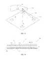
- FIG. 3is a schematic diagram of a note pad in accordance with one embodiment of the invention.
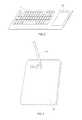
- FIG. 4is a schematic diagram of a note pad in accordance with one embodiment of the invention integrated into a docking station or lap desk.
- FIG. 5is a schematic diagram of an e-book embodiment of the invention.
- FIG. 6is an exploded view of the capture device of the invention.
- FIG. 7is a top view of the display device in accordance with one embodiment of the system of the invention showing a virtual keyboard with the target overlaid in transparent mode.
- FIG. 8is a top view of the display device in accordance with one embodiment of the system of the invention showing a second virtual keyboard with targets, in this case, thumbs, overlaid in transparent mode.
- FIG. 9is a schematic diagram of an embodiment of the system of the invention.
- FIG. 10is a block diagram of the MTAC of an embodiment of the invention.
- FIG. 11is a schematic side view of a touch pad module with the proximity hovering feature in accordance with an embodiment of the invention.
- FIG. 12Ais a schematic view showing, in the upper portion thereof, a graphical representation of the detected relative position of a hovering finger, the hovering finger shown relative to the input surface in the lower portion thereof.
- FIG. 12Bis a schematic view showing, in the upper portion thereof, a graphical representation of the detected relative position of landed fingers, the landed fingers shown relative to the input surface in the lower portion thereof.
- FIG. 13is a table showing representative classifications of inputs.
- FIG. 14is a flow chart of a first method of the invention.
- FIG. 15is a schematic view of the triangulation step in accordance with an embodiment of the invention.
- FIG. 16is a schematic view of a hybrid touchpad module in accordance with an embodiment of the invention.
- FIG. 17is a flow chart of a second alternative method of the invention.
- FIG. 18is a schematic diagram of a graphical user interface in accordance with one embodiment of the invention.
- FIG. 19is a schematic diagram of a pressure map in accordance with one embodiment of the invention.
- FIG. 20is a chart of pressure vs. state of a contact surface in accordance with one embodiment of the invention.
- FIG. 21is a block diagram of the control board in accordance with one embodiment of the invention.
- FIG. 22is an exploded view of the note pad in accordance with one embodiment of the invention.
- FIG. 23is an electrical schematic diagram of a notepad in accordance with one embodiment of the invention.
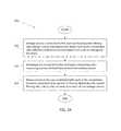
- FIG. 24is a flow chart of a method of operation of the pressure sensor layer in accordance with one embodiment of the invention.
- a system 10includes an interconnected computer processor 12 (housed in a PC or multimedia device 14 , or housed in the MTAC itself wherein the MTAC interacts with a display, such as a TV), a display device 16 , an input device 20 , and a wireless hub 22 .
- the computer processor 12 and operating system 24executes instructions 26 for carrying out the method 30 of the invention (described in association with FIGS. 14 and 17 ).
- the instructions 26are executed on the OS 24 to receive and process data received from such MTAC 20 in order to display representations 32 of a user's finger 36 and at least a representation 33 of the input field 40 of the MTAC 20 on the display device 16 so as to mimic the relative location and input functions performed by a user on the MTAC 20 .
- one embodiment of the inventionprovides remote, virtual on-screen data input.
- the computer processor 12 and operating system (OS) 24execute instructions 26 for carrying out the method 30 of the invention.
- the multi-touch input surface 44 of the MTAC 20is integrated onto a housing 46 .
- the MTAC 20incorporates functionality of emerging touch data input devices such as those available from Stantum in France, STMicroelectronics in Switzerland, Cypress Semiconductors in the U.S., Avago Technologies in the U.S. and Synaptics in the US.
- the MTACincludes a touch surface 40 .
- the input device 46may be readily removable while being in wireless contact with the wireless hub 22 and/or communication device (not shown) integrated in the MTAC 20 .
- the MTAC 20 , 20 ′, 20 ′′is used in multiple systems such as in a keyboard 1 (the device is located, for example, to the right of or below a computer keyboard), in a lapdesk 2 , operated jointly with a notebook 3 , or notepad, in a stand-alone wireless battery powered device, operated jointly with a PC, a notebook, or notepad (a wireless link allows communication between the MTAC 20 and the PC 14 ).
- the deviceis embedded in a dual screen tablet 4 , one screen being the active display 5 , the second screen 6 being a display devoted to virtual ink display 6 , further comprising the pressure sensor 9 underneath.
- the virtual ink display 6is part of the active display 5 , allowing for a single display embedded device, again with the pressure sensor 9 underneath.
- the MTAC 20includes a multilayer assembly 60 including a bottom layer 8 , an intermediate pressure sensor layer 9 and a top layer 11 .
- the bottom layer 8is a rigid surface that provides a mechanical support for writing, as the two upper layers are flexible.
- the bottom layer 8can exhibit some degree of flexibility, for example to appear more like a paper notepad.
- the pressure sensor layer 9is a pressure sensor layer detecting touch and pressure on the capture active area.
- the layer 9is connected to multiple voltage sources and multiple ammeters, defining multiple electrical conductive paths, whose conductivity is modulated by the applied pressure on that path, described in more detail below with respect to FIG. 22 . At least one ammeter measures current emitted from more than one of said voltage sources.
- PERATECHwww.peratech.com
- keyboard membrane technologyinvolving silver ink and carbon ink sandwiched between 2 PET membranes can be used.
- capacitive pressure sensorscan be used.
- a capacitive pressure sensoris constructed with a compressible material located between two electrodes.
- the top layer 11is a flexible touch-sensitive passive LCD display, utilizing for example a reflective bistable cholesteric liquid crystal laminated between two conductive-polymer coated polyethyleneterephthalate substrates, such as found in Reflex technology supplied by Kentdisplays (www.kentdisplays.com).
- the passive LCD technologyis touch-sensitive in that whatever is written down on the LCD is impressed graphically thanks to its liquid crystal physics properties (applied pressure changes the crystal particles orientation and light properties).
- the stylus 15When the stylus 15 is writing on the device, it leaves a visible trace allowing the user to produce a drawing though no real ink has flown.
- More advanced passive LCD displaysinclude multiple colors.
- the MTAC 20further comprises a control board 200 (depicted in FIG. 21 ). This board is described below. Among other functionality, the control board 200 classifies the measured pressure map into various pressure points with position and force (either from finger, stylus, or palm).
- the MTAC 20is connected to the personal computer built-in processor, either through USB, Bluetooth, other 2.4 GHz RF link, SP1 or I2C interface, so that the device and the PC 14 can communicate bi-directionally.
- Transmitted packets informationcomprises pressure activity data, time stamps, touchpoint identifier, proximity, and type.
- the target 36although typically a user's finger or fingers, can also be various other things such as, but not limited to, a user's hand or hands, arm or arms, identifiers on gloves, rings, etc., a stylus or styluses, pencil or pencils, pen or pens, and a pointer or pointers.
- the representation of the target 36 and the input surface 40 for display in a window of the display 16are transparent (i.e., displayed in transparent mode), permitting viewing of screen content visually underneath the representation of the target or input field.
- the user 34types information into the input device 20 in the normal way.
- the userenters text naturally with his or her two thumbs 37 while holding the MTAC 20 , 20 ′, 20 ′′ in hand.
- both of the user's thumbs 37are displayed and correctly placed on the virtual representation 32 on the display 16 as the thumbs are hovering over and/or touching the MTAC surface 40 , 44 .
- the MTAC 20includes a touch surface 40 providing a keyboard input field 42 , as well as a touch surface 44 for use on the housing 46 of an auxiliary pointing or number input device 48 , at the selection of the user 34 .
- a touch surface 40providing a keyboard input field 42 , as well as a touch surface 44 for use on the housing 46 of an auxiliary pointing or number input device 48 , at the selection of the user 34 .
- Separate touch surfaces 40 and 44allow the use of a lesser expensive single touch surface for touch surface 40 , through which text inputs may be entered, whereas the more expensive multi-touch surface 44 is minimized, yet can control the modes of operation of the single touch surface 40 , by allowing multi-touch inputs to the multi-touch surface 44 to allow toggling between key overlays, for example.
- the input device 48may be readily removable while being in wireless contact with the hub 22 and/or communication device (not shown) integrated in the MTAC 20 .
- proximity sensorsare suitable for use with the invention. Sensors which work by emitting an electromagnetic or electrostatic field, or a beam of electromagnetic radiation (infrared, for instance), and looks for changes in the field or return signal may be used.
- the types of suitable sensors availableinclude but are not limited to inductive, capacitive, capacitive displacement, eddy-current, magnetic, electromagnetic, photocell, laser range-finding, sonar, radar, Doppler effect, passive thermal infrared, passive optical, ionizing radiation reflective sensors, reed switch, hall effect, resistive variation, conductive variation, echo (e.g. sound be it ultrasonic or radar), optical pattern recognition technologies and micro air flux change (detections of air current variations between sensors as opposed to macro flux changes).
- a capacitive or photoelectric sensormight be suitable for a plastic target while an inductive proximity sensor requires a metal target and a Hall Effect sensor a magnetic target.
- Optical sensing using, for example, infrared proximity sensinginvolves using an optical sensing circuit to pulse light, e.g., infrared light, emitted from an emitter which, should an object such as a user's finger be present in front of or above the emitter (e.g., a laser diode or LED), reflects off of the user's finger and back toward an infrared detector (e.g., a photodiode, a type of photodetector capable of converting light into either current or voltage, depending upon the mode of operation), generally adjacent or concentric with the emitter and configured to detect changes in light intensity.
- pulse lighte.g., infrared light
- an emittere.g., a laser diode or LED
- an infrared detectore.g., a photodiode, a type of photodetector capable of converting light into either current or voltage, depending upon the mode of operation
- the touch parameteris a parameter of sufficient proximity, which is typically contact, at which proximity a touch signal indicating touch is sent to the processor 12 , thereby allowing traditional keypad use with the benefits of touch pad use.
- Avago Technology's proximity sensorsare reflective, non-contact sensors in a small form factor SMT package that offer detection ranges from near zero to 60 mm with analogue-output.
- their model APDS-9101is a low cost, integrated reflective sensor incorporating infrared LED and a phototransistor designed to provide object detection and non-contact proximity sensing in the detection range of near 0 mm to 12 mm.
- the proximity sensors described in U.S. patent application Ser. No. 11/418,832, entitled OPTICAL SLIDER FOR INPUT DEVICES, the content of which is incorporated by reference hereto, available from Logitech, Inc. of Fremont, Calif.,are also suitable for this purpose.
- Capacitive proximity sensinga preferred means of proximity sensing, takes advantage of the fact of a measurable change in capacitance over a sensor when a target is and is not present within its sensing range. If a change from a nominal or initial state is detected, then it is assumed that a target is present.
- Another suitable capacitive proximity sensor system for use in the inventionis available from Freescale Semiconductor, Inc of Austin, Tex. Freescale's proximity controller model MPR08X controls multiple proximity sensors thereby allowing control of several different applications from one sensor. By multiplexing the electrodes, a single sensor is able to detect at multiple points. For example, proximity capacitive-touch sensors manage multiple configurations of touch pads, sliders, rotary positions and mechanical keys for user interfaces.
- proximity sensorse.g., Freescale's model no MC33794
- Electromagnetic proximity sensingscans a region around an antenna adjacent the input interface, constantly monitoring electromagnetic field changes in the vicinity of the antenna.
- a self-diagnostic functiondetects when there is a field change which corresponds to the presence of an object, e.g., a user's finger, near the antenna. In order to allow more discrete detection, multiple antennae can be used.
- a video camera with a defined focuscan be used, in which images seen by the video camera are recognized using pattern recognition technology which itself may use artificial intelligence techniques to classify a sensed object.
- pattern recognition technologywhich itself may use artificial intelligence techniques to classify a sensed object.
- neural network technologyidentifies the pattern of an object, classifying the same as a hand, finger, stylus, pointer or an anomaly, for each sensor.
- Ultrasonic proximity sensinguses technology found in nature and used by bats to identify and avoid proximate objects in flight. Adaptation of the invention to use ultrasonic proximity sensing is considered within the capacity of someone of ordinary skill in the art when using the present disclosure as a guide.
- a metal ring or a user glovehaving metal, magnetic, or plastic parts strategically located to optimize the function of the interface with such sensors resulting in advantageous features such as more accuracy in movement detection, etc.
- some sensorshave adjustments of the nominal range of detection or means to report a graduated detection distance.
- proximity detectorsare disclosed in IEC 60947-5-2, published by the International Electrotechnical Commission, the content of which is incorporated by reference thereto.
- a schematic diagram of an alternative MTAC 20 ′′includes a single multi-touch surface 45 made up of the multilayer assembly 60 , 60 ′, 60 ′′ of the invention.
- a grid 50 of delineations of key input fields or zones 52can be pre-printed on the touch surface 40 or 45 , or the touch surface can be an integrated touch display screen which displays the delineations of the key input fields or zones.
- the capacitive touch screen 45is printed so as to define key fields 52 which, if touched within the field, trigger the registration of the corresponding letter, symbol or command selected.
- such fields 52can be defined by displaying the fields on a liquid crystal touch screen.
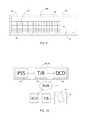
- the MTAC 20 , 20 ′, 20 ′′has a proximity sensing subsystem 54 (PSS), a transceiver (T/R) 56 adapted to transmit and receive encoded data according to a communications protocol via IR, RF, “BLUETOOTH”#, “WiFi”TM through a data connection device (DCD, such as an antenna) 58 for communicating data and command signals to processor 12 , preferably via the wireless hub 22 (via, for example, a second data connection device and transceiver).
- the PSS 54is optional, and a system in accordance with an embodiment of the present invention may be based on touch (without proximity sensing).
- the instructions 26are executable on the processor 12 for receiving data inputs from a MTAC 20 , 20 ′, 20 ′′.
- the instructions 26when data is transmitted from the proximity sensing subsystem 54 , cause the display of a virtual representation 33 of the MTAC 20 , 20 ′, 20 ′′ (or the input field 42 , 44 thereof) on the display device 16 along with a virtual representation 32 of the target 36 , positioned on the display relative to a representation of at least the input field of the MTAC 20 , 20 ′, 20 ′′ in an orientation which recreates, in 2D plan view, the real world relative position of the target 36 with respect to the real world MTAC 20 , 20 ′, 20 ′′.
- the instructions 26then cause the reception of data inputs from the MTAC 20 , 20 ′, 20 ′′ and processing such in a manner appropriate to the class of data transmitted, whether representative of an input letter, word, or command (e.g., shift or control functions).
- the MTAC 20 ′includes a multilayer assembly 60 ′ with added proximity sensing.
- the multilayer assembly 60 ′is made up of a top layer 11 ′, under which is a multitouch module 9 ′.
- the multitouch module 9 ′is made up of the upper pressure sensor layer 9 , followed by a touchpad sensor subassembly 61 .
- the top layer 11 ′is a flexible touch-sensitive passive LCD display 11 ′ (as already described with respect to layer 11 ).
- the touchpad sensor subassembly 61 of the multitouch module 9 ′may be based on the “TRUETOUCH”TM touchscreen solution available from Cypress Semiconductor Corp of San Jose, Calif. This device integrates capacitive proximity finger hovering functionality.
- the touchpad sensor assembly 61has proximity sensors 62 integrated on a surface 64 in a tight array or cluster 68 .
- a thin film backlight 70is added on top of the array 68 of proximity sensors 62 , followed by a glass panel 72 (thickness approximately 0.6-0.8 mm), optionally with paint masking to mark input areas, which seals the assembly in a housing (not shown).
- proximity sensors 62locate the target 36 , in this case a finger, as it approaches the multi-touch surface 74 .
- the circle 75 indicating the relative position of the target 36 on a grid 76is unfilled when no touch is detected. When proximity has been detected, the circle 75 appears, and its size typically indicates the distance d of the target 36 from the multi-touch surface 74 .
- the processor 12interprets the touch or hover information as shown in the grids 76 , 76 ′ above the schematics of the approaching or touching action in the figures. From the grid location, the processor 12 is able to read location, determine whether touch has occurred, discern how many targets 36 are involved as well as estimate the distance d from touch interface that target is and, when a touch is indicated (by the filled circles 80 ), determine how large a surface is being touched.
- MTAC 20 ′, 20 ′′includes a multitouch module 60 ′, 60 ′′ therein
- data input and the visualization thereofmay be performed as described in a number of prior art patents.
- a touch locationis determined based on location data pertaining to touch input on the touch screen, wherein the touch input is intended to activate one of the plurality of virtual keys.
- Each of the plurality of virtual keyshas a set of at least one key location corresponding to it.
- a parametersuch as physical distance
- the determined parametersare processed to determine one of the virtual keys.
- the determined one virtual keymay be the virtual key with a key location (or more than one key location, on average) being closest to the touch location.
- a signalis generated indicating activation of the determined one of the virtual keys.
- a signalis generated indicating activation of the identified virtual key. Referring again to FIG. 7 , the signal can be the highlighting or glowing of that particular key 82 .
- a table 90 showing representative classifications of inputs in accordance with one embodiment of the present inventionis provided. Such should be considered as a typical, nonexhaustive example of input classification. Simple, intuitive action on the part of the user is required in order to distinguish between modes of operation of the MTAC 20 , 20 ′, 20 ′′.
- a typical examplewould be where a single target 36 is sensed by the PSS 54 , the inputs received from the MTAC 20 , 20 ′, 20 ′′ are classified as single inputs of letters, numbers or symbols, preferably augmented by “SWYPE” technology (facilitating gesture based input).
- the inputs received from the MTAC 20 , 20 ′, 20 ′′are classified as command or macro inputs. Where two targets 36 in close proximity to one another are sensed, the inputs received are classified as pointing device control inputs.
- Such pointer inputsexecute a pointer subroutine which processes the data received as pointer data inputs, controlling a cursor on the display screen in any known manner. Such convention provides a transparent input mode to the user.
- the inputs made to the MTAC 20 , 20 ′, 20 ′′can have any meaning defined by any suitable protocol, and may even be combined with inputs to other input devices (e.g. from standard keyboard inputs to eyelid wink detection, for example) to create new more complex meanings.
- distinction between inking and keyingmay be made via the classification process, based for example, on pressure segmentation results, in which a touch point is defined to be a finger or a stylus. For example, upon detection of contact or landing, the size of the “footprint” of the target and/or the associated pressure may be used to classify the input.
- the MTAC 20 , 20 ′, 20 ′′is suitably programmed to disable functionality that is dedicated to keying, such as the overlaying of a virtual keyboard 32 on the remote display 16 . Therefore, the inputs classified and recognized may advantageously be used to turn on or turn off functionality to suit the task at hand. This saves memory and processing resources and improves reaction time. Further, detection of inking prompts a query of the user via a popup window, to disable hovering and proximity features, in order to avoid movements in the proximity of the inking surface 11 , 11 ′ and 11 ′′ being misinterpreted as inking, and further reducing memory and processing resources.
- the MTAC 20 , 20 ′, 20 ′′may readily be adapted to sense data including proximity, distance, landing speed, touch, contact area, pressure segmentation, pressure distribution, heat, shape, footprint, pattern, capacitance, measured wavelength, biometric data, flux, induction, sound, and conductivity,
- the method 30 of the inventionincludes the following steps: step 100 , reading proximity signal from each proximity sensing electrode; step 102 , checking if proximity signals are above a feature detection threshold and classify them as high proximity signals; step 104 , classifying high proximity signals into clusters based on corresponding sensing electrode locations which indicate a single feature detection; step 106 , identifying the local highest proximity signal, for each cluster; step 110 , calculating the XYZ position of each feature by processing each local highest proximity signal with adjacent proximity electrode signals using triangulation methods; and step 112 , displaying each feature on the virtual keyboard at correct X-Y location and using depth cues corresponding to Z position.
- the triangulation of a target 36 using a plurality of proximity sensors 114is known in the art. Such processes are used for GPS location of objects to calculate a position based detections from several distant satellites.
- location of a target 36 using four proximity sensors 114is depicted.
- the target 36is measured as being a distance of d 1 , d 2 , d 3 and d 4 from the corresponding sensors 114 .
- a triangulation algorithmis solved based on the corresponding inputs d 1 to d 4 , thus locating the point 116 of the target in 3D space.
- the MTAC 20 ′′includes a multilayer assembly 60 ′′ with added proximity sensing.
- the multilayer assembly 60 ′′is made up of a top layer 11 ′′ under which is a multitouch module 9 ′′.
- the multitouch module 9 ′′is made up of the upper pressure sensor layer 9 , followed by a touchpad sensor subassembly 61 ′.
- the touchpad sensor subassembly 61 ′uses a multiple 3D proximity sensing module 120 .
- the module 120is made up of a PCB 122 , proximity sensors 124 , a touchpad module 126 having ITO dual layers or a regular touchpad PCB, and a glass panel 8 , 132 .
- the PCB 122has integrated thereon, several proximity sensors 124 arranged in a cluster or an array (which cluster can take the form of a rectangle surrounding the touchpad module 126 , described below).
- a touchpad module 126itself made up of a touchpad PCB 128 .
- an ITO (Indium Tin Oxide) dual layer 129may be used.
- a glass panelis then placed thereon, to seal the assembly within the housing (not shown). In this way, the assembly is able to measure proximity of the target by calculating the 3D position of the target based on the detected distances of the array of sensors (e.g., as illustrated in FIG. 15 above).
- movement detection technology in video imagessuch as that described in U.S. Pat. No. 6,760,061, to Nestor, Inc, the content of which is incorporated by reference, may be used to recognize an object by tracking changes in luminescence in defined tiles across the video image taken of the user's hand above the input device, whereas selection of particular keys is sensed by traditional capacitive touch sensors. Consequently, a single video camera embedded in the MTAC 20 ′′ can sense the position and movement of targets 36 above the MTAC which, together with a processor 12 and instructions 26 ′ operating thereon, are first inverted (e.g., step 154 of the method 140 below described in connection with FIG.
- a pattern recognition step or stepsmay be performed in which a user's hand is recognized according to the shape viewed and classified as a hand in which a particular finger is likely to be closest the keyboard or touch interface 40 , 44 , 45 (after comparison with stored shapes of hands representative of hands having a particular extended finger for example).
- Such particular fingermay then be associated with the closest sensed object to the capacitive sensors and so this portion of the sensed hand is registered to the closest finger location, thereby allowing an accurate overlay of the hand image 32 on the virtual input area 33 .
- the transparent image 32 used for the target 36may be an actual video image of the target captured by the video camera 138 .
- the method 140 for recognizing and projecting video images 32 of a target 36includes several steps.
- a first step 142the target 36 is videoed as it approaches the input field 40 , 44 , 45 , 74 .
- the target 36is recognized using pattern recognition software and classify by type.
- a third step 146using pattern recognition software, the image is compared with a library of patterns for such target type and the type identified (together with associated subpatterns).
- a fourth step 150using proximity sensors 54 , 62 , 114 , 124 , the portion of the target 36 closest to input device surface 40 , 44 , 45 , 74 is located.
- a fifth step 152the portion of the target 36 recognized as most proximate to input surface 40 , 44 , 45 , 74 is registered to the location associated with the portion (e.g. 116 of FIG. 15 ) of the target 36 detected by proximity sensors 54 , 62 , 114 , 124 to be closest to input surface 40 , 44 , 45 , 74 .
- the video imageis inverted as necessary to accommodate a differing viewpoint from the user.
- the video image of the targetis overlaid in proper registration to input field, preferably in transparent mode.
- the processor 12includes instructions in an instruction set for automatic system activation when the proximity sensor 54 , 62 , 114 , 124 detects a target 36 in appropriate proximity to the MTAC 20 , 20 ′, 20 ′′.
- a representation 32 of the target 36is displayed on the display 16 .
- a representation 33 of the input field 40 , 44is displayed on the display 16 .
- Sensing of proximity of a target 36 to the MTAC 20 , 20 ′, 20 ′′triggers the display of a virtual representation 33 of at least the input field 40 , 44 , 45 of the MTAC on the display 16 .
- the proximity sensor 54 , 62 , 114 , 124remains active even in sleep mode, such sensing can be used to power up the MTAC 20 , 20 ′, 20 ′′, or to activate otherwise power consuming functionality (such as an illumination feature, a backlighting module or a local display), in a system ready mode. Further, when a user 34 sees his virtual finger 32 appear on the display 16 , then he can adjust the position of his virtual finger relative to the virtual input field 33 without ever having to glance at the physical MTAC 20 , 20 ′, 20 ′′ or his own finger.
- the proximity sensing subsystem 54detects multiple targets 36 and transmits relative location data dynamically, in real time to the OS 24 of the PC 14 , for display of multiple fingers of one or more hands over the virtual MTAC 33 , so as to further allow a user to focus their eyes only on the display 16 in order to better understand and correct his or her finger motions so as to improve his or her input throughput into the system of the invention.
- This ability of focusing only on the computer displayshould reduce eye fatigue usually caused by having to glance at the physical input device and then refocus on the more distant computer display.
- such an embodimentoverlays the detected hands or arms on the display 16 which although physically distant from the user 34 , is nonetheless the focus of the audience's attention, thereby facilitating communication for such presentations.
- system 10 and method 30 , 140 of the inventionpermits sizing, relocation and hiding of the virtual representation 33 of the MTAC 20 , 20 ′, 20 ′′ on the display 16 in a conventional manner, such as clicking to close, resize or move a window.
- the virtual representation 32 of the target 36is displayed on the display 16 in a 2D plan view using various cues such as distance/depth cue such as: variation of the target size, variation of the target color and/or transparency, variation of the target shadow relative position, variation of the target shadow color and/or transparency, variation of the target shadow blur and displaying arrows encoding the distance between the target and the touch input device surface.
- Soundmay also be used, where the sound varies as the target approaches or retreats from the MTAC 20 , 20 ′, 20 ′′.
- Such virtual representation 32 of the target 36may be a simple abstraction thereof, such as a mouse cursor but may also be any other shape such as a simplified representation of a human finger.
- a suitable virtual representation 32 of a human fingermay be an elongated rectangle (not shown), with a rounded or pointed input end, which, for simplicity is projected on the display 16 in a vertical orientation. In such an embodiment, the relative location of end of the rectangle corresponding to the input end of the target is of importance. The opposite end is presented for visual comprehension only (i.e., that such representation is that of a finger).
- inking modethe user interacts directly (direct interaction) with the device surface (as opposed to a graphic tablet where the user does not look at the pen tip and looks instead at the PC, this is a so called indirect experience).
- the PC 14While the user is inking, the PC 14 is receiving the pen tip activity (stylus location, pressure, type) and stores this activity in the PC internal memory as a stream of data. After drawing completion, the PC 14 produces an equivalent drawing, either in the form of vector, bitmap, or other format (knowing the stylus tip trajectory and pressure allows building a computer model similar to the actual drawing as displayed on the ink display). Building the equivalent drawing based on the stylus tip activity is achieved in the PC 14 thanks to special software referred to as the drawing reconstruction program.
- the stylus 15leaves a trace on the inking display thanks to the special LCD passive display technology.
- the stylus tipis also tracked in real time with a resistive pressure sensor located below the inking display. Hence the drawing on the display can be reconstructed independently thanks to all the pressure activity packets transmitted to the PC 14 .
- the pressure activity(location and pressure amount, type . . . ) is transmitted to the PC 14 immediately as it occurs (on-the-fly). Alternatively it is stored in the MTAC 20 and then transmitted as a whole when the process is finished (see below). Timestamps define the instants when the pressure activity takes place. They can be transmitted as part of the activity packet. This allows reproducing the “film” of the drawing, making possible later editing of the drawings, for example by changing the color of the strokes that took place between time A and time B. Alternatively, no time stamps are transmitted; instead the approximate time of data reception, as measured by the PC, is used.
- the useris satisfied with the drawing, and initiates the “activate” gesture or equivalently a mechanical button, which brings the display back to its initial blank state and signal this event to the computer.
- Erasing the inking displayis a feature available with passive LCD technology.
- generating multiple voltage pulses of different polarity and voltagebrings the passive LCD display in its erased state.
- the embedded pressure sensordetects the gestures such as the pre-defined activate gesture.
- the activate gestureis a double 3-fingers tap.
- the activate event(from button or from gesture) is also sent to the PC 14 . This event launches a pre-defined target application, reconstructs the drawing, and pastes the drawing in the defined application.
- Possible target applicationsinclude graffiti in FACEBOOKTM, digital Post-It, messaging applications.
- Activity information packetsare stored in the PC 14 or in the MTAC 20 . If the pressure activity packets are transmitted continuously as the user is drawing, activity packets are stored in the PC 14 . If the pressure activity packets are stored in the MTAC 20 during the drawing process, the packets are sent as a whole after the activate event is detected. Storing all activity in the MTAC 20 can be beneficial as it allows a drawing to be acquired even when the PC 14 is in its OFF state. The activity information is then transmitted only when a PC 14 is linked to the device. Expanding on this, multiple drawings can be stored locally while the PC 14 is in OFF state, each drawing being stored by a new activate gesture or button push.
- the usermay desire to draw with a real pen on real paper.
- the same devicecan be used in this case: simply apply a sheet of paper onto the device sensitive surface thanks to the embedded clip mechanism. Draw on the paper (note the passive LCD below the paper—if present—will also be marked by the pen action on the paper). When finished, the user removes the paper, and pushes the activate button or gesture, as in the case where no paper is present. Adding paper brings a more natural pen on paper interaction that some users will prefer. For this use case, the passive LCD display needs not be mounted on the device for further cost savings.
- Finger controlis based on indirect interaction.
- Mouse cursor controlis an example of indirect interaction, in that moving the mouse moves a cursor, which in turn controls a GUI.
- each fingercontrols a graphical object, which interacts with other controls in the GUI.
- the finger iconsare shown on the PC 14 active display.
- a finger/target icon display programmonitors the finger state and updates the display in a manner that transcribes the finger activity, such as finger position, applied pressure, and orientation.
- This programreads touch points data transmitted from the MTAC 20 via its interface, or alternatively processes the complete pressure map and determine the touch after the complete pressure map has been sent to the PC 14 via its interface.
- the finger activityis displayed on a transparent overlay, e.g., the fingers are made visible on top of the regular GUI 16 (Windows, Mac, Chrome . . . ). This environment is visible as if the overlay was not present, except obviously for the added finger icons 13 .
- the finger icons 13 on the display device 16move in real time as per the real finger location on the MTAC 20 .
- a simple graphical transcription of the finger activityis to display a colored circle 170 (constant diameter) at a location corresponding to the actual finger location.
- a cross 172is located in the center.
- the circle 170can be made thicker when the finger pressure is increased, as described in FIG. 19 .
- the line thicknessis measured by dR 174 , namely deltaRadius, the difference between external and internal radius.
- Representing PressureAny value between light pressure and hard press are shown graphically by filling the circle 170 that represents this finger 36 . Filling the circle 170 starts from the outside towards the center.
- Pressure display sensitivity(alpha in FIG. 19 ) can be set as a parameter. This parameter defines how much pressure is needed to fill the circle 170 . Note that filling (e.g. dR) versus applied pressure need not be a linear function. In the linear case, the line thickness dR is alpha multiplied by the applied pressure, where alpha is an adjustable constant value.
- Each finger 36can be either active (enough pressure is applied) or inactive (little pressure).
- the statemay be encoded with a different color (or by grayscale differences).
- ActiveBlue circle with an adjustable transparency (parameter). Active color can also be adjusted as a parameter.
- InactiveGrey circle with intensity and an adjustable transparency. Inactive color can also be adjusted.
- transition from inactive to active and vice-versacan be highlighted by audio feedback, such as clicks or other sounds.
- first threshold 180to distinguish when a finger 36 enters the active state 182 .
- this threshold 180 “dRa”for deltaRadius_Activate
- dRacan be adjusted as a parameter.
- the pressure associated to dRais simply pressure which exceeds dRa/alpha.
- this threshold 184 “dRd”for deltaRadius_Deactivate
- dRdcan be adjusted as a parameter.
- the pressure associated to dRdis simply dRd/alpha.
- a warning messagemay be triggered upon reaching pressure threshold 184 , to help avoid damage to the MTAC 20 , 20 ′, 20 ′′.
- a user trained to touchscreen direct interactionas for example by using a touchscreen in Windows 7 will immediately apply his skills to the MTAC 20 in finger control mode, getting similar performance, but with the additionally benefits that the body posture is much more comfortable, that there is no longer any visual occlusion on the target (precise control is facilitated), and finally the PC screen is not spoiled by finger traces.
- a touch digitizer virtual driver used in the inventionis a driver that behaves as if digitizer or equivalent touchscreen hardware were present. It generates equivalent events or messages (again, even though no digitizer or touchscreen are physically present—from the operating system perspective, there is no way to distinguish if the event or message is generated by a “real” hardware or by a “virtual” hardware simulated in the virtual driver).
- the finger icon display programWhen a touch point is detected as active, the finger icon display program signals the activity of the active touch points to the touch digitizer virtual driver, such activity including for example touchdown, touchup, or touchmove.
- the finger icon display program and the virtual driverare combined.
- the virtual driverissues touchpoints messages (in Windows 7, WM_TOUCHDOWN, WM_TOUCH_UP, WM_TOUCHMOVE) including their virtual touch coordinates computed by scaling touch points physical coordinates on the active surface by a factor equal to the ratio of display device dimensions to the device active surface dimensions (e.g. the equivalent scaled coordinates on the active screen rather than the MTAC 20 physical coordinates).
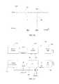
- a power management block 202generates the required supply voltages for the other blocks. Batteries are connected to this block 202 in order to supply energy to the system 200 .
- a microcontroller 204called ⁇ C in the following, has M outputs controlling (e.g. driving as they are connected to internal binary voltage sources or to internal DAC outputs) the columns 206 of the pressure sensor panel 212 . Furthermore, it has N inputs (e.g. receiving as they are connected to an internal ADC), which are connected to the rows 210 of the pressure sensor panel 212 . Two buttons are connected to ⁇ C input, in order to detect user action on these.
- the ⁇ C 204also controls a block called LCD control 214 , thanks to some control lines dC (dark control, with result when asserted that the display gets uniformly dark) and bC (bright control, with result that the display gets uniformly bright).
- the LCD control 214generates high voltage pulses (positive and negative) on the lines topC and bottomC that are connected to top and bottom layers of the Reflex LCD display 216 . By activating single polarity only, or both polarities, for high voltage pulses, the net result is an erased display with either bright or dark appearance.
- a RF stage 220emits and receives via its 2.4 GHz channel the information flowing from and to the PC.
- Other embodimentsuse, for example, a USB interface and a cable.
- a passive sensor panel 212is shown. It consists of a lower flexible membrane 230 with conductive rows 210 facing upward, a separation layer 232 built of conductive material such as carbon ink, and an upper flexible membrane 234 with conductive columns 206 facing downward.
- carbon inkis deposited on both lower and upper flexible membrane such that when the membranes are laminated together, the 2 carbon ink layers come into both physical and electrical contact. Given this construction and the carbon electrical properties, the electrical resistance R between each pair of row 210 and column 206 will decrease based on pressure applied at the crossing of said row-column pair.
- a voltageis applied between said column 206 and ground, and the current flowing into the row 210 is measured.
- the resistanceis then obtained by dividing the applied voltage by the current flowing into the row 210 (typically measured with help of a transimpedance amplifier, which drives the row terminal to ground).
- driving the voltage on each column 206is sequential, and so is the readout of the current flowing into each row 210 .
- Sequential activationis needed to evaluate the conductance for each cell in isolation (a cell being defined by the area nearby the crossing of a column-row). Inactive column 206 and rows 210 are usually maintained at a 0V potential. This sequential scanning limits the scan rate.
- a 16 column ⁇ 16 row matrixhas 256 pressure cells (if the pitch is 4 mm, the active area is then 6.4 mm ⁇ 6.4 mm).
- the scanning rateis M ⁇ T.
- N inputsare acquired sequentially (one acquisition stage and an N-to-1 demultiplexer), the scanning rate is then N ⁇ M ⁇ T.
- Tis the measurement duration of a single cell. In order to reach sufficient rate, usually above 50 Hz, the measurement duration T needs to be very small, at the expense of signal-to-noise ratio (“SNR”). Having insufficient SNR results in noisy measurements, which in turn results in pressure fluctuations and/or inability to detect touchpoints applied with very low force.
- SNRsignal-to-noise ratio
- MIMOmultiple input, multiple output
- the current injected in each row 210is the sum of the current contributions generated by each column 206 in isolation. There is a need to separate the individual contribution from each column drive source out of the total current.
- the total current flowing in rowR( 1 ) 210 ′is the source of multiple contributions from columnD( 1 ) to columnD( 3 ) 206 ′ drive voltage sources (only columnD( 1 ) to columnD( 3 ) are displayed, whereas up to M columns can be driven at the same time), as shown by 3 resistors 240 connecting columnD( 1 ) to columnD( 3 ) to rowR( 1 ), each having a conductivity G 11 , G 21 , G 31 , respectively.
- neighboring rows(rowR( 0 ), not shown, and rowR( 2 )) are connected to ground during measurements of rows 1 , 3 , 5 , . . . (all odd rows).
- odd rows 210are set to ground when even rows are measured.
- This multiplexing of measurements for odd and even rows 210is implemented with help of N/2 analog two-to-one demultiplexer (not shown), each with 2 inputs and 1 output.
- the 2 inputsare odd and even rows successively, and the output is connected to the ⁇ C ADC input (one of N/2) also successively; the select signal to the multiplexer is controlled by the ⁇ C 204 in order to measure odd or even rows alternatively, as per the programmed scanning sequence.
- all rows 210are measured at once and neighboring rows are not connected to ground.
- the N rowsare directly connected to the N analog ADC inputs of the ⁇ C, as shown in FIG. 21 .
- a load resistor Rmcan be connected between row i terminal and ground, and the voltage across Rm is then proportional to the current.
- a transimpedance amplifier(not shown), providing a virtual ground to row i terminal, is used. The transimpedance acts as an ammeter as its voltage output is directly proportional to the current flowing into its input.
- orthogonal functionsare described in the literature, such as the Walsh functions, the Haar functions, or other wavelets functions.
- a set of 16 Walsh functions selected among the first 32 functionsare used.
- the selection criterionis based for example on suppressing Walsh functions having many contiguous bits in either +1 and ⁇ 1 output state.
- Other optimization criteriacan be used to select the best functions among a larger set of orthogonal functions.
- the receive signal for each row 210(which is the sum of current contribution from each column 206 ) is cross-correlated with each one of the multiple modulation function, yielding a total of M sets of measurements for each row.
- the methodworks equally well for both continuous-time and discrete time signals, but we describe here the discrete time case for ease of explanation and implementation.
- x_j[n]the measured waveform from row j at instant n (square bracket indicates the time index for discrete time signals).
- Cross-correlation output of the measured waveform at row j with drive at column iis y_ij[n].
- y — ij[n]⁇ ( x — j[k]*f — i[L ⁇ ( n ⁇ k )]) where ⁇ applies to k from ⁇ infinity to + infinity.
- y_ij[n]can be understood as the result of convolution of the measured row current with a matched filter having impulse response equal to the time reverse of the modulation function f_i[n] (to which a time shift of value L is further applied).
- Matched filterhas the desirable property to maximize the SNR when trying to detect a signal in random noise.
- the matched filter as defined hereis optimized for white noise, a good model for the environment described here. For other type of noise, a similar matched filter definition can be obtained, as defined by the theory of matched filter further taking into account the autocorrelation function of the noise.
- the matched filter operationnot only minimizes the impact of noise but also completely eliminate current contributions from the other columns voltage drive. This is a direct result of using a set of orthogonal functions and the linear nature of the resistive separation layer.
- Both Y_ij and F_iiare the projection of the signals x_j[n] and f_i[n] on the signal subspace defined by f_i[n].
- the complete sets of G(i,j)can be computed in either one or two scans.
- a scan operationinvolves driving the columns with the complete drive function f_i[n] of duration L, simultaneously acquiring the total current x_j[n] for N or N/2 rows, then after drive completion (2 scans for the latter), the cross-correlation computation is activated in the ⁇ C program, from which all values of G(i,j) are estimated and stored in internal memory.
- the set of conductanceare computed for each cell (i,j). Since the material in the separation layer has a conductance that grows with applied pressure, the two-dimensional (2D) map of conductance as stored in the ⁇ C internal memory can be used as a good approximation of the 2D pressure map.
- the 2D pressure mapreports the amount of pressure on each cell of the pressure sensor. In order for inking or finger control to take place, there is a need to convert this map into a list of touch points.
- the first stepis to segment contiguous zones of non-zero pressure into blobs. This is a well-covered technique, and is described in http://en.wikipedia.org/wiki/Blob_detection, the content of which is incorporated herein by reference thereto.
- Each segment of the pressure map (touchpoint)is categorized (based on the segment dimension) as either one of:
- segmented pressure profileis further modeled by a 2D Gaussian or elliptic distribution.
- the outcome of the model fittingprovides more attributes to the segment under consideration:
- the output of the segmentation processis a list of active touchpoints including all their attributes.
- the distribution center(including fractional accuracy) is identified to be the pen tip position and the peak value is directly linked to the pen pressure. Tip position and pen pressure allow for a good reproduction of the drawing on the passive LCD to be stored in the PC 14 .
- the equivalent ellipseis drawn on the active screen, as described above (description above covers circle objects, but ellipse at a given orientation can be used for more realistic finger representation).
- a sensing subsystemsenses an object on the MTAC 20 which triggers the display of a virtual image 32 of the MTAC 20 on the computer display screen 16 .
- Such sensingcan be used to power up the MTAC 20 , or to activate otherwise power consuming functionality, in a system ready mode.
- a usersees his virtual finger 32 appear on the computer screen, then he can adjust the position of his virtual finger relative to the virtual MTAC 20 without ever having to glance at the physical MTAC 20 or his own finger.
- the sensing subsystemdetects multiple fingers and transmits relative location data dynamically, in real time to the OS 24 of the PC 14 , for display of multiple fingers of one or more hands over the virtual MTAC 20 , so as to further allow a user to focus their eyes only on the computer display screen in order to better understand and correct his or her finger motions so as to improve his or her input throughput into the system of the invention.
- This ability of focusing only on the computer displayreduces eye fatigue usually caused by having to glance at the physical input device and then refocus on the more distant computer display.
- system and method of the inventionpermits sizing, relocation and hiding of the virtual MTAC 20 image on the display 16 in a conventional manner, such as clicking to close, resize or move a window.
- a method 300 of operation of the pressure sensor layer 9 of the MTAC 20 , 20 ′, 20 ′′includes several steps.
- the voltage sourcesare connected to the first layer conductive paths, driving said voltage sources simultaneously, where each source is modulated with a different modulation function, said modulation function taken from a set of orthogonal functions.
- the ammetersare connected to the third layer conductive paths, measuring current emitted from at least one voltage source.
- measured currentis cross-correlated with each of the modulation functions contributing to current, to thereby determine the current flowing into at least one ammeter from each of said voltage source.
- a user experienceis created of using a touch screen display device remotely from such device, without requiring that the user touch the display and further not requiring a touch screen display device.
- the inventionallowing the creation of a one to one copy of the real world in the virtual world, providing a user with flexibility of location, relative orientation, etc that the virtual world provides (e.g., allowing typing while reclining in a comfortable chair, while standing and working at a distance from a large screen, while presenting information on a large screen to others or collaborating in real time with others while interacting with a computing device having a large screen display).
- the inventionallows a user to input data into a virtual keyboard remotely from a displayed virtual image of the keyboard.
- the inventionpermits a user more comfort and flexibility in interacting with a PC or personal entertainment device, such as a multimedia player.
- the device 20provides a good drawing experience as the user sees the drawing at the location where the stylus 15 is acting (unlike graphic tablets). Because there is no need to manage actively a display as in tablet or eBook cases (pressure directly updates the screen due to the physical properties of this Reflex technology), the device 20 can be built at a low cost.
- system and method of the inventioncontemplates the use, sale and/or distribution of any goods, services or information having similar functionality described herein.
- the terms “comprises”, “comprising”, or any variation thereof,are intended to refer to a non-exclusive listing of elements, such that any process, method, article, composition or apparatus of the invention that comprises a list of elements does not include only those elements recited, but may also include other elements described in this specification.
- the use of the term “consisting” or “consisting of” or “consisting essentially of”is not intended to limit the scope of the invention to the enumerated elements named thereafter, unless otherwise indicated.
- Other combinations and/or modifications of the above-described elements, materials or structures used in the practice of the present inventionmay be varied or otherwise adapted by the skilled artisan to other design without departing from the general principles of the invention.
Landscapes
- Engineering & Computer Science (AREA)
- General Engineering & Computer Science (AREA)
- Theoretical Computer Science (AREA)
- Human Computer Interaction (AREA)
- Physics & Mathematics (AREA)
- General Physics & Mathematics (AREA)
- Position Input By Displaying (AREA)
Abstract
Description
y—ij[n]=Σ(x—j[k]*f—i[L−(n−k)])
where Σ applies to k from − infinity to + infinity.
y—ij[n]=Σ(x—j[k]*f—i[L−(n−k)])
where Σ applies to k from 0 to 2L.
y—ij[L]=Y—ij=Σ(x—j[k]*f—i[k])
F—ii=Σ(f—i[k]*f—i[k)])
G(i,j)=Y—ij/F—ii
- 1. Lindeberg, T. (1991)Discrete Scale-Space Theory and the Scale-Space Primal Sketch, PhD thesis, Department of Numerical Analysis and Computing Science, Royal Institute of Technology, S-100 44 Stockholm, Sweden, May 1991. (ISSN 1101-2250. ISRN KTH NA/P-91/8-SE) (The grey-level blob detection algorithm is described in section 7.1)
- 2. Lindeberg, Tony,Scale-Space Theory in Computer Vision, Kluwer Academic Publishers, 1994, ISBN 0-7923-9418-6
The above articles are incorporated herein by reference in their entirety.
- Keyboard1 (
FIG. 3 )FIG. 4 Lapdesk 2Notebook 3Dual screen tablet 4Active display 5- Second screen/
virtual ink display 6 Pressure sensor 9FIG. 6 Multilayer assembly 60Bottom layer 8- Intermediate
pressure sensor layer 9 - Modified
middle layer 9′,9″ - Top layer/inking
surface 11FIG. 18 Finger icon 13FIGS. 1-3 System 10Processor 12- PC, set-top box,
multimedia device 14 Stylus 15Display 16- Input device, MTAC20 (entire keyboard),
MTAC 20′,MTAC 20″ Wireless hub 22Operating system 24Instructions 26Method 30- Representation of
target 32 - Representation of
input field 33 - User34
- Target/user's
finger 36 Thumbs 37Principal input device 38Principal input surface 40- Keying
input field 42 - Multi-touch input surface,
touch surface 44 Input device 46Auxiliary input device 48FIG. 7 Glowing key 82FIG. 9 Multi-touch surface 45Grid 50Zones 52FIG. 10 - Proximity Sensing Subsystem (PSS)54
Transceiver 56- Data connection device (DCD)58
Instructions 26FIG. 11 - Input device,
MTAC 20′ Multilayer assembly 60′Multitouch module 9′- Top layer/inking
surface 11′ Touchpad sensor subassembly 61Proximity sensors 62- Surface of
touchpad module 64 PCB 66- Array of
proximity sensors 68 Thin backlight 70- Glass panel72
FIG. 12A Multitouch surface 74Circle 75Grid 76- Distance d
FIG. 12B - Filled
circles 80 Grid 76′Key 82FIG. 13 - Table90
FIG. 14 Step 100Step 102Step 104Step 106Step 110Step 112FIG. 15 Sensors 114- d1
- d2
- d3
- d4
FIG. 16 - Input device,
MTAC 20″ Multilayer assembly 60″- Top layer/inking
surface 11″ Multitouch module 9″Touchpad sensor subassembly 61′Proximity sensing module 120PCB 122Proximity electrodes 124Touchpad module 126- Touchpad PCB128
- ITO dual layer129
Glass panel 132FIG. 17 - Method140
- Step one142
- Step two144
- Step three146
- Step four150
- Step five152
- Step six154
FIG. 19 Colored circle 170Cross 172dR 174FIG. 20 First threshold 180Active state 182Second threshold 184FIG. 21 Control board 200Power management block 202Microcontroller 204Columns 206Rows 210Pressure sensor panel 212LCD control 214LCD display 216RF Stage 220FIG. 22 - Upper
flexible membrane 230 - Resistance R
Separation layer 232FIG. 23 - ColumnD(3)206′
- Row(1)210′
Resistors 240FIG. 24 Method 300Step 302Step 303Step 304
Claims (41)
Priority Applications (2)
| Application Number | Priority Date | Filing Date | Title |
|---|---|---|---|
| US13/047,962US9092129B2 (en) | 2010-03-17 | 2011-03-15 | System and method for capturing hand annotations |
| US14/327,622US20140368455A1 (en) | 2011-03-15 | 2014-07-10 | Control method for a function of a touchpad |
Applications Claiming Priority (3)
| Application Number | Priority Date | Filing Date | Title |
|---|---|---|---|
| US31463910P | 2010-03-17 | 2010-03-17 | |
| US36616910P | 2010-07-21 | 2010-07-21 | |
| US13/047,962US9092129B2 (en) | 2010-03-17 | 2011-03-15 | System and method for capturing hand annotations |
Related Child Applications (1)
| Application Number | Title | Priority Date | Filing Date |
|---|---|---|---|
| US14/327,622Continuation-In-PartUS20140368455A1 (en) | 2011-03-15 | 2014-07-10 | Control method for a function of a touchpad |
Publications (2)
| Publication Number | Publication Date |
|---|---|
| US20110248941A1 US20110248941A1 (en) | 2011-10-13 |
| US9092129B2true US9092129B2 (en) | 2015-07-28 |
Family
ID=44760577
Family Applications (1)
| Application Number | Title | Priority Date | Filing Date |
|---|---|---|---|
| US13/047,962Active2031-08-02US9092129B2 (en) | 2010-03-17 | 2011-03-15 | System and method for capturing hand annotations |
Country Status (2)
| Country | Link |
|---|---|
| US (1) | US9092129B2 (en) |
| CN (2) | CN102364413A (en) |
Cited By (44)
| Publication number | Priority date | Publication date | Assignee | Title |
|---|---|---|---|---|
| US20150271624A1 (en)* | 2014-03-24 | 2015-09-24 | R2Z Innovations, Inc. | System for communicating with computing devices in an alternating electric field environment |
| US20150346868A1 (en)* | 2014-05-30 | 2015-12-03 | Samsung Electronics Co., Ltd. | Electronic device including ito electrode pattern and manufacturing method thereof |
| US9417754B2 (en) | 2011-08-05 | 2016-08-16 | P4tents1, LLC | User interface system, method, and computer program product |
| US9608506B2 (en) | 2014-06-03 | 2017-03-28 | Apple Inc. | Linear actuator |
| US9640048B2 (en) | 2009-09-30 | 2017-05-02 | Apple Inc. | Self adapting haptic device |
| US9652040B2 (en) | 2013-08-08 | 2017-05-16 | Apple Inc. | Sculpted waveforms with no or reduced unforced response |
| US9671889B1 (en) | 2013-07-25 | 2017-06-06 | Apple Inc. | Input member with capacitive sensor |
| US9715301B2 (en) | 2015-08-04 | 2017-07-25 | Apple Inc. | Proximity edge sensing |
| US9779592B1 (en) | 2013-09-26 | 2017-10-03 | Apple Inc. | Geared haptic feedback element |
| US9830782B2 (en) | 2014-09-02 | 2017-11-28 | Apple Inc. | Haptic notifications |
| US9851828B2 (en) | 2013-03-15 | 2017-12-26 | Apple Inc. | Touch force deflection sensor |
| US9886093B2 (en) | 2013-09-27 | 2018-02-06 | Apple Inc. | Band with haptic actuators |
| US9911553B2 (en) | 2012-09-28 | 2018-03-06 | Apple Inc. | Ultra low travel keyboard |
| US9928950B2 (en) | 2013-09-27 | 2018-03-27 | Apple Inc. | Polarized magnetic actuators for haptic response |
| US10006937B2 (en) | 2015-03-06 | 2018-06-26 | Apple Inc. | Capacitive sensors for electronic devices and methods of forming the same |
| US10007343B2 (en) | 2016-03-31 | 2018-06-26 | Apple Inc. | Force sensor in an input device |
| US10013058B2 (en) | 2010-09-21 | 2018-07-03 | Apple Inc. | Touch-based user interface with haptic feedback |
| US10039080B2 (en) | 2016-03-04 | 2018-07-31 | Apple Inc. | Situationally-aware alerts |
| US10048789B2 (en) | 2014-02-12 | 2018-08-14 | Apple Inc. | Force determination employing sheet sensor and capacitive array |
| US10120446B2 (en) | 2010-11-19 | 2018-11-06 | Apple Inc. | Haptic input device |
| US10126817B2 (en) | 2013-09-29 | 2018-11-13 | Apple Inc. | Devices and methods for creating haptic effects |
| US10162444B2 (en) | 2012-12-14 | 2018-12-25 | Apple Inc. | Force sensor incorporated into display |
| US10168814B2 (en) | 2012-12-14 | 2019-01-01 | Apple Inc. | Force sensing based on capacitance changes |
| US10198123B2 (en) | 2014-04-21 | 2019-02-05 | Apple Inc. | Mitigating noise in capacitive sensor |
| US10236760B2 (en) | 2013-09-30 | 2019-03-19 | Apple Inc. | Magnetic actuators for haptic response |
| US10268272B2 (en) | 2016-03-31 | 2019-04-23 | Apple Inc. | Dampening mechanical modes of a haptic actuator using a delay |
| US10276001B2 (en) | 2013-12-10 | 2019-04-30 | Apple Inc. | Band attachment mechanism with haptic response |
| US10353467B2 (en) | 2015-03-06 | 2019-07-16 | Apple Inc. | Calibration of haptic devices |
| US10386970B2 (en) | 2013-02-08 | 2019-08-20 | Apple Inc. | Force determination based on capacitive sensing |
| US10459521B2 (en) | 2013-10-22 | 2019-10-29 | Apple Inc. | Touch surface for simulating materials |
| US10481691B2 (en) | 2015-04-17 | 2019-11-19 | Apple Inc. | Contracting and elongating materials for providing input and output for an electronic device |
| US10566888B2 (en) | 2015-09-08 | 2020-02-18 | Apple Inc. | Linear actuators for use in electronic devices |
| US10599223B1 (en) | 2018-09-28 | 2020-03-24 | Apple Inc. | Button providing force sensing and/or haptic output |
| US10606343B2 (en)* | 2017-04-01 | 2020-03-31 | Intel Corporation | Keyboard for virtual reality |
| US10622538B2 (en) | 2017-07-18 | 2020-04-14 | Apple Inc. | Techniques for providing a haptic output and sensing a haptic input using a piezoelectric body |
| US10691211B2 (en) | 2018-09-28 | 2020-06-23 | Apple Inc. | Button providing force sensing and/or haptic output |
| US10852913B2 (en) | 2016-06-21 | 2020-12-01 | Samsung Electronics Co., Ltd. | Remote hover touch system and method |
| US10866683B2 (en) | 2018-08-27 | 2020-12-15 | Apple Inc. | Force or touch sensing on a mobile device using capacitive or pressure sensing |
| US11232917B2 (en)* | 2020-05-01 | 2022-01-25 | Epic Semiconductors Inc | Electronic smart switch |
| US11380470B2 (en) | 2019-09-24 | 2022-07-05 | Apple Inc. | Methods to control force in reluctance actuators based on flux related parameters |
| US11709655B2 (en) | 2018-02-23 | 2023-07-25 | Samsung Electronics Co., Ltd. | Electronic device and control method thereof |
| US11809631B2 (en) | 2021-09-21 | 2023-11-07 | Apple Inc. | Reluctance haptic engine for an electronic device |
| US11977683B2 (en) | 2021-03-12 | 2024-05-07 | Apple Inc. | Modular systems configured to provide localized haptic feedback using inertial actuators |
| US12079393B2 (en)* | 2022-05-05 | 2024-09-03 | Nokia Technologies Oy | Tactile feedback |
Families Citing this family (138)
| Publication number | Priority date | Publication date | Assignee | Title |
|---|---|---|---|---|
| US8866347B2 (en) | 2010-01-15 | 2014-10-21 | Idex Asa | Biometric image sensing |
| US8421890B2 (en)* | 2010-01-15 | 2013-04-16 | Picofield Technologies, Inc. | Electronic imager using an impedance sensor grid array and method of making |
| KR20110103140A (en)* | 2010-03-12 | 2011-09-20 | 삼성전자주식회사 | Multi-touch and proximity object sensing device for selectively irradiating light |
| US8811948B2 (en) | 2010-07-09 | 2014-08-19 | Microsoft Corporation | Above-lock camera access |
| KR101695818B1 (en)* | 2010-07-28 | 2017-01-13 | 엘지전자 주식회사 | Mobile terminal and Method for controlling virtual key pad thereof |
| US10298614B2 (en)* | 2010-11-29 | 2019-05-21 | Biocatch Ltd. | System, device, and method of generating and managing behavioral biometric cookies |
| US10728761B2 (en) | 2010-11-29 | 2020-07-28 | Biocatch Ltd. | Method, device, and system of detecting a lie of a user who inputs data |
| US10834590B2 (en) | 2010-11-29 | 2020-11-10 | Biocatch Ltd. | Method, device, and system of differentiating between a cyber-attacker and a legitimate user |
| US10474815B2 (en) | 2010-11-29 | 2019-11-12 | Biocatch Ltd. | System, device, and method of detecting malicious automatic script and code injection |
| US11269977B2 (en) | 2010-11-29 | 2022-03-08 | Biocatch Ltd. | System, apparatus, and method of collecting and processing data in electronic devices |
| US10747305B2 (en) | 2010-11-29 | 2020-08-18 | Biocatch Ltd. | Method, system, and device of authenticating identity of a user of an electronic device |
| US20190158535A1 (en)* | 2017-11-21 | 2019-05-23 | Biocatch Ltd. | Device, System, and Method of Detecting Vishing Attacks |
| US11210674B2 (en) | 2010-11-29 | 2021-12-28 | Biocatch Ltd. | Method, device, and system of detecting mule accounts and accounts used for money laundering |
| US10949514B2 (en) | 2010-11-29 | 2021-03-16 | Biocatch Ltd. | Device, system, and method of differentiating among users based on detection of hardware components |
| US10917431B2 (en) | 2010-11-29 | 2021-02-09 | Biocatch Ltd. | System, method, and device of authenticating a user based on selfie image or selfie video |
| US10685355B2 (en)* | 2016-12-04 | 2020-06-16 | Biocatch Ltd. | Method, device, and system of detecting mule accounts and accounts used for money laundering |
| US10404729B2 (en) | 2010-11-29 | 2019-09-03 | Biocatch Ltd. | Device, method, and system of generating fraud-alerts for cyber-attacks |
| US10262324B2 (en) | 2010-11-29 | 2019-04-16 | Biocatch Ltd. | System, device, and method of differentiating among users based on user-specific page navigation sequence |
| US10970394B2 (en) | 2017-11-21 | 2021-04-06 | Biocatch Ltd. | System, device, and method of detecting vishing attacks |
| US10069837B2 (en)* | 2015-07-09 | 2018-09-04 | Biocatch Ltd. | Detection of proxy server |
| US11223619B2 (en) | 2010-11-29 | 2022-01-11 | Biocatch Ltd. | Device, system, and method of user authentication based on user-specific characteristics of task performance |
| US10949757B2 (en) | 2010-11-29 | 2021-03-16 | Biocatch Ltd. | System, device, and method of detecting user identity based on motor-control loop model |
| US10776476B2 (en) | 2010-11-29 | 2020-09-15 | Biocatch Ltd. | System, device, and method of visual login |
| US10897482B2 (en) | 2010-11-29 | 2021-01-19 | Biocatch Ltd. | Method, device, and system of back-coloring, forward-coloring, and fraud detection |
| US10621585B2 (en) | 2010-11-29 | 2020-04-14 | Biocatch Ltd. | Contextual mapping of web-pages, and generation of fraud-relatedness score-values |
| US10586036B2 (en) | 2010-11-29 | 2020-03-10 | Biocatch Ltd. | System, device, and method of recovery and resetting of user authentication factor |
| US12101354B2 (en)* | 2010-11-29 | 2024-09-24 | Biocatch Ltd. | Device, system, and method of detecting vishing attacks |
| US9965094B2 (en) | 2011-01-24 | 2018-05-08 | Microsoft Technology Licensing, Llc | Contact geometry tests |
| US8988087B2 (en) | 2011-01-24 | 2015-03-24 | Microsoft Technology Licensing, Llc | Touchscreen testing |
| US8982061B2 (en)* | 2011-02-12 | 2015-03-17 | Microsoft Technology Licensing, Llc | Angular contact geometry |
| US9542092B2 (en) | 2011-02-12 | 2017-01-10 | Microsoft Technology Licensing, Llc | Prediction-based touch contact tracking |
| AU2012214109A1 (en)* | 2011-02-13 | 2013-09-12 | Apolon IVANKOVIC | Visual proximity keyboard |
| US8913019B2 (en) | 2011-07-14 | 2014-12-16 | Microsoft Corporation | Multi-finger detection and component resolution |
| US9983785B2 (en)* | 2011-07-28 | 2018-05-29 | Hewlett-Packard Development Company, L.P. | Input mode of a device |
| US9134561B2 (en) | 2011-11-01 | 2015-09-15 | Kent Displays Incorporated | Writing tablet information recording device |
| US8896559B2 (en)* | 2011-11-04 | 2014-11-25 | Harold J. Goldbaum | Wire-array pressure and movement sensor |
| US9785281B2 (en) | 2011-11-09 | 2017-10-10 | Microsoft Technology Licensing, Llc. | Acoustic touch sensitive testing |
| US20130136377A1 (en)* | 2011-11-29 | 2013-05-30 | Samsung Electronics Co., Ltd. | Method and apparatus for beautifying handwritten input |
| US9075443B2 (en)* | 2011-12-27 | 2015-07-07 | Maxim Integrated Products, Inc. | Gesture detection and compact representation thereof |
| CN102572567A (en)* | 2011-12-28 | 2012-07-11 | 惠州Tcl移动通信有限公司 | Interaction system and interaction method for handheld device and television UI (User Interface) |
| EP2613227B1 (en)* | 2012-01-06 | 2020-04-29 | Samsung Electronics Co., Ltd | Input apparatus and control method thereof |
| US20130176270A1 (en)* | 2012-01-09 | 2013-07-11 | Broadcom Corporation | Object classification for touch panels |
| US8914254B2 (en) | 2012-01-31 | 2014-12-16 | Microsoft Corporation | Latency measurement |
| US9354748B2 (en) | 2012-02-13 | 2016-05-31 | Microsoft Technology Licensing, Llc | Optical stylus interaction |
| US9298236B2 (en) | 2012-03-02 | 2016-03-29 | Microsoft Technology Licensing, Llc | Multi-stage power adapter configured to provide a first power level upon initial connection of the power adapter to the host device and a second power level thereafter upon notification from the host device to the power adapter |
| US9075566B2 (en) | 2012-03-02 | 2015-07-07 | Microsoft Technoogy Licensing, LLC | Flexible hinge spine |
| USRE48963E1 (en) | 2012-03-02 | 2022-03-08 | Microsoft Technology Licensing, Llc | Connection device for computing devices |
| US9360893B2 (en) | 2012-03-02 | 2016-06-07 | Microsoft Technology Licensing, Llc | Input device writing surface |
| US9870066B2 (en) | 2012-03-02 | 2018-01-16 | Microsoft Technology Licensing, Llc | Method of manufacturing an input device |
| US9460029B2 (en) | 2012-03-02 | 2016-10-04 | Microsoft Technology Licensing, Llc | Pressure sensitive keys |
| US8873227B2 (en) | 2012-03-02 | 2014-10-28 | Microsoft Corporation | Flexible hinge support layer |
| US9064654B2 (en) | 2012-03-02 | 2015-06-23 | Microsoft Technology Licensing, Llc | Method of manufacturing an input device |
| US9426905B2 (en) | 2012-03-02 | 2016-08-23 | Microsoft Technology Licensing, Llc | Connection device for computing devices |
| CN103365405B (en)* | 2012-04-01 | 2016-12-14 | 联想(北京)有限公司 | A kind of input equipment and input method |
| US20130300590A1 (en) | 2012-05-14 | 2013-11-14 | Paul Henry Dietz | Audio Feedback |
| US9009630B2 (en) | 2012-06-05 | 2015-04-14 | Microsoft Corporation | Above-lock notes |
| US10031556B2 (en) | 2012-06-08 | 2018-07-24 | Microsoft Technology Licensing, Llc | User experience adaptation |
| US9019615B2 (en) | 2012-06-12 | 2015-04-28 | Microsoft Technology Licensing, Llc | Wide field-of-view virtual image projector |
| US9684382B2 (en)* | 2012-06-13 | 2017-06-20 | Microsoft Technology Licensing, Llc | Input device configuration having capacitive and pressure sensors |
| US9073123B2 (en) | 2012-06-13 | 2015-07-07 | Microsoft Technology Licensing, Llc | Housing vents |
| US9459160B2 (en)* | 2012-06-13 | 2016-10-04 | Microsoft Technology Licensing, Llc | Input device sensor configuration |
| US9063693B2 (en) | 2012-06-13 | 2015-06-23 | Microsoft Technology Licensing, Llc | Peripheral device storage |
| WO2013188318A1 (en)* | 2012-06-13 | 2013-12-19 | Microsoft Corporation | Input device writing surface |
| AU2013204058A1 (en)* | 2012-06-28 | 2014-01-16 | Apolon IVANKOVIC | An interface system for a computing device and a method of interfacing with a computing device |
| US20140002339A1 (en)* | 2012-06-28 | 2014-01-02 | David Brent GUARD | Surface With Touch Sensors for Detecting Proximity |
| US8773591B1 (en)* | 2012-08-13 | 2014-07-08 | Nongqiang Fan | Method and apparatus for interacting with television screen |
| US8964379B2 (en) | 2012-08-20 | 2015-02-24 | Microsoft Corporation | Switchable magnetic lock |
| US20140055731A1 (en)* | 2012-08-23 | 2014-02-27 | Microsoft Corporation | Integrated force localizer and digitizer and/or lcd drive for cholesteric liquid crystal display |
| US9891759B2 (en) | 2012-09-28 | 2018-02-13 | Apple Inc. | Frustrated total internal reflection and capacitive sensing |
| US8654030B1 (en) | 2012-10-16 | 2014-02-18 | Microsoft Corporation | Antenna placement |
| EP2908970B1 (en) | 2012-10-17 | 2018-01-03 | Microsoft Technology Licensing, LLC | Metal alloy injection molding protrusions |
| US8952892B2 (en) | 2012-11-01 | 2015-02-10 | Microsoft Corporation | Input location correction tables for input panels |
| WO2014081104A1 (en)* | 2012-11-21 | 2014-05-30 | Lg Electronics Inc. | Multimedia device for having touch sensor and method for controlling the same |
| US20140168093A1 (en)* | 2012-12-13 | 2014-06-19 | Nvidia Corporation | Method and system of emulating pressure sensitivity on a surface |
| JP2014127188A (en)* | 2012-12-27 | 2014-07-07 | Toshiba Corp | Shaping device and method |
| US10578499B2 (en) | 2013-02-17 | 2020-03-03 | Microsoft Technology Licensing, Llc | Piezo-actuated virtual buttons for touch surfaces |
| US20140245181A1 (en)* | 2013-02-25 | 2014-08-28 | Sharp Laboratories Of America, Inc. | Methods and systems for interacting with an information display panel |
| US9158411B2 (en)* | 2013-07-12 | 2015-10-13 | Tactual Labs Co. | Fast multi-touch post processing |
| US9304549B2 (en) | 2013-03-28 | 2016-04-05 | Microsoft Technology Licensing, Llc | Hinge mechanism for rotatable component attachment |
| US10006756B2 (en) | 2013-04-02 | 2018-06-26 | United Technologies Corporation | Flexible reference system |
| US10222911B2 (en)* | 2013-04-12 | 2019-03-05 | Semiconductor Energy Laboratory Co., Ltd. | Semiconductor device and driving method of the same |
| FR3004551A1 (en)* | 2013-04-15 | 2014-10-17 | Fogale Nanotech | MULTIZONE CAPACITIVE DETECTION METHOD, DEVICE AND APPARATUS USING THE METHOD |
| JP5862610B2 (en)* | 2013-06-17 | 2016-02-16 | コニカミノルタ株式会社 | Image display device, display control program, and display control method |
| KR102229812B1 (en)* | 2013-07-11 | 2021-03-22 | 삼성전자 주식회사 | Inputting apparatus and method of computer by using smart terminal having electronic pen |
| CN105637460B (en)* | 2013-10-18 | 2018-11-27 | 肯特显示器公司 | Write tablet computer information-recording apparatus |
| US20150153897A1 (en)* | 2013-12-03 | 2015-06-04 | Microsoft Corporation | User interface adaptation from an input source identifier change |
| US20150181152A1 (en)* | 2013-12-20 | 2015-06-25 | Skylight Healthcare Corporation | Systems, devices and methods for interactive and bidirectional message overlay on a communications signal |
| US9448631B2 (en) | 2013-12-31 | 2016-09-20 | Microsoft Technology Licensing, Llc | Input device haptics and pressure sensing |
| JP2015128918A (en)* | 2014-01-06 | 2015-07-16 | 株式会社東海理化電機製作所 | Operation device |
| US9759854B2 (en) | 2014-02-17 | 2017-09-12 | Microsoft Technology Licensing, Llc | Input device outer layer and backlighting |
| US10120420B2 (en) | 2014-03-21 | 2018-11-06 | Microsoft Technology Licensing, Llc | Lockable display and techniques enabling use of lockable displays |
| CN106489116B (en)* | 2014-04-21 | 2019-08-16 | 苹果公司 | Distribution of forces for multi-touch input devices for electronic devices |
| CN103902130A (en)* | 2014-04-29 | 2014-07-02 | 哈尔滨金梧桐科技发展有限公司 | Handwriting input device integrating keyboard and mouse functions |
| US9766806B2 (en)* | 2014-07-15 | 2017-09-19 | Microsoft Technology Licensing, Llc | Holographic keyboard display |
| US10324733B2 (en) | 2014-07-30 | 2019-06-18 | Microsoft Technology Licensing, Llc | Shutdown notifications |
| US9513671B2 (en) | 2014-08-01 | 2016-12-06 | Microsoft Technology Licensing, Llc | Peripheral retention device |
| US10191986B2 (en) | 2014-08-11 | 2019-01-29 | Microsoft Technology Licensing, Llc | Web resource compatibility with web applications |
| US9705637B2 (en) | 2014-08-19 | 2017-07-11 | Microsoft Technology Licensing, Llc | Guard band utilization for wireless data communication |
| US10019059B2 (en)* | 2014-08-22 | 2018-07-10 | Sony Interactive Entertainment Inc. | Glove interface object |
| US9397723B2 (en) | 2014-08-26 | 2016-07-19 | Microsoft Technology Licensing, Llc | Spread spectrum wireless over non-contiguous channels |
| CN105446947B (en)* | 2014-08-29 | 2018-04-20 | 珠海金山办公软件有限公司 | A kind of method and device for selecting newly-built annotation input mode |
| US9424048B2 (en) | 2014-09-15 | 2016-08-23 | Microsoft Technology Licensing, Llc | Inductive peripheral retention device |
| US10038443B2 (en)* | 2014-10-20 | 2018-07-31 | Ford Global Technologies, Llc | Directional proximity switch assembly |
| US9971406B2 (en)* | 2014-12-05 | 2018-05-15 | International Business Machines Corporation | Visually enhanced tactile feedback |
| CN105987781B (en)* | 2015-02-10 | 2021-01-05 | 北京纳米能源与系统研究所 | Dynamic stress sensor, preparation method and dynamic stress measurement system |
| US10416799B2 (en) | 2015-06-03 | 2019-09-17 | Microsoft Technology Licensing, Llc | Force sensing and inadvertent input control of an input device |
| US10222889B2 (en) | 2015-06-03 | 2019-03-05 | Microsoft Technology Licensing, Llc | Force inputs and cursor control |
| CN106293189B (en)* | 2015-06-10 | 2023-10-20 | 宸鸿科技(厦门)有限公司 | Touch control device |
| KR102282215B1 (en) | 2015-06-22 | 2021-07-27 | 삼성디스플레이 주식회사 | Liquid crystal display device |
| GB2539705B (en) | 2015-06-25 | 2017-10-25 | Aimbrain Solutions Ltd | Conditional behavioural biometrics |
| CN105182583B (en)* | 2015-09-17 | 2018-11-23 | 京东方科技集团股份有限公司 | A kind of display panel and preparation method thereof, display device and its health monitor method |
| US10620803B2 (en)* | 2015-09-29 | 2020-04-14 | Microsoft Technology Licensing, Llc | Selecting at least one graphical user interface item |
| CN106557193A (en)* | 2015-09-30 | 2017-04-05 | 南昌欧菲光科技有限公司 | Touch display unit |
| KR102443203B1 (en)* | 2015-10-27 | 2022-09-15 | 삼성전자주식회사 | Method for Operating Electronic Device and the Electronic Device |
| CN105652488B (en)* | 2016-01-14 | 2017-10-10 | 京东方科技集团股份有限公司 | One kind can write liquid crystal display device and preparation method thereof, driving method |
| US10061385B2 (en) | 2016-01-22 | 2018-08-28 | Microsoft Technology Licensing, Llc | Haptic feedback for a touch input device |
| TWI609314B (en)* | 2016-03-17 | 2017-12-21 | 鴻海精密工業股份有限公司 | Interface operating control system method using the same |
| KR102231025B1 (en)* | 2016-06-06 | 2021-03-23 | 다이니폰 인사츠 가부시키가이샤 | Sorting method of writing sheet for touch panel pen, touch panel system, writing sheet for touch panel pen, touch panel and display device |
| GB2552032B (en) | 2016-07-08 | 2019-05-22 | Aimbrain Solutions Ltd | Step-up authentication |
| CN106484293A (en)* | 2016-09-29 | 2017-03-08 | 努比亚技术有限公司 | A kind of applications trigger system based on proximity transducer and mobile terminal |
| US10198122B2 (en)* | 2016-09-30 | 2019-02-05 | Biocatch Ltd. | System, device, and method of estimating force applied to a touch surface |
| US10579784B2 (en) | 2016-11-02 | 2020-03-03 | Biocatch Ltd. | System, device, and method of secure utilization of fingerprints for user authentication |
| US10877575B2 (en)* | 2017-03-06 | 2020-12-29 | Microsoft Technology Licensing, Llc | Change of active user of a stylus pen with a multi user-interactive display |
| US10397262B2 (en) | 2017-07-20 | 2019-08-27 | Biocatch Ltd. | Device, system, and method of detecting overlay malware |
| CN108459709B (en)* | 2018-02-02 | 2021-06-22 | 河南大学 | Wearable input device and method based on optical image capture and processing |
| EP3769197A1 (en)* | 2018-03-20 | 2021-01-27 | Preciflex SA | Finger-fluid interfacing method and device |
| US10997402B2 (en)* | 2018-07-03 | 2021-05-04 | Fuji Xerox Co., Ltd. | Systems and methods for real-time end-to-end capturing of ink strokes from video |
| CN110413143B (en)* | 2018-11-20 | 2020-04-28 | 中天智领(北京)科技有限公司 | Man-machine interaction method based on laser radar |
| CN110134292B (en)* | 2019-05-24 | 2022-12-16 | 京东方科技集团股份有限公司 | Handwriting input device, preparation method thereof and handwriting input equipment |
| US11132058B1 (en)* | 2019-09-12 | 2021-09-28 | Facebook Technologies, Llc | Spatially offset haptic feedback |
| TR202011169A1 (en)* | 2020-07-14 | 2022-01-21 | Tim Akilli Kiyafetleri Ve Bilisim Teknolojisi Anonim Sirketi | A SMART WEAR PRODUCT THAT MATCHES FABRIC |
| CN111984116A (en)* | 2020-07-31 | 2020-11-24 | 成都易瞳科技有限公司 | VR perception touch device |
| US11606353B2 (en) | 2021-07-22 | 2023-03-14 | Biocatch Ltd. | System, device, and method of generating and utilizing one-time passwords |
| CN113589739A (en)* | 2021-08-10 | 2021-11-02 | 四川长虹网络科技有限责任公司 | Non-contact control device and method |
| WO2023070469A1 (en)* | 2021-10-28 | 2023-05-04 | 京东方科技集团股份有限公司 | Liquid crystal handwriting panel, handwriting device, and control method therefor |
| TWI792688B (en)* | 2021-11-17 | 2023-02-11 | 虹彩光電股份有限公司 | Cholesterol liquid crystal display device |
| USD1063938S1 (en)* | 2023-03-22 | 2025-02-25 | Leiju Electronic Technology (Dongguan) Co., Ltd. | Keyboard |
| CN119127032B (en)* | 2024-10-30 | 2025-04-01 | 荣耀终端股份有限公司 | Element level position adjusting method, device and storage medium |
Citations (27)
| Publication number | Priority date | Publication date | Assignee | Title |
|---|---|---|---|---|
| US5138322A (en) | 1991-08-20 | 1992-08-11 | Matrix Engineering, Inc. | Method and apparatus for radar measurement of ball in play |
| US5509650A (en) | 1994-10-14 | 1996-04-23 | Macdonald; Lee | Automated practice target for goal-oriented sports and a method of training using the practice target |
| US6144366A (en) | 1996-10-18 | 2000-11-07 | Kabushiki Kaisha Toshiba | Method and apparatus for generating information input using reflected light image of target object |
| US6292130B1 (en) | 1999-04-09 | 2001-09-18 | Sportvision, Inc. | System for determining the speed and/or timing of an object |
| US6304665B1 (en) | 1998-04-03 | 2001-10-16 | Sportvision, Inc. | System for determining the end of a path for a moving object |
| US20020003726A1 (en)* | 2000-05-17 | 2002-01-10 | Ricoh Company, Ltd. | Information recording medium and information processing apparatus |
| US20020196238A1 (en) | 2001-06-20 | 2002-12-26 | Hitachi, Ltd. | Touch responsive display unit and method |
| US6760061B1 (en) | 1997-04-14 | 2004-07-06 | Nestor Traffic Systems, Inc. | Traffic sensor |
| WO2005077466A2 (en) | 2004-02-11 | 2005-08-25 | Sensitec Ag | Method and device for displaying parameters of the trajectory of at least one moving object |
| US20060026521A1 (en) | 2004-07-30 | 2006-02-02 | Apple Computer, Inc. | Gestures for touch sensitive input devices |
| US20060197753A1 (en)* | 2005-03-04 | 2006-09-07 | Hotelling Steven P | Multi-functional hand-held device |
| US20070018970A1 (en) | 2000-12-22 | 2007-01-25 | Logitech Europe S.A. | Optical slider for input devices |
| US20070085837A1 (en)* | 2005-10-17 | 2007-04-19 | Eastman Kodak Company | Touch input device with display front |
| US20070171210A1 (en) | 2004-07-30 | 2007-07-26 | Imran Chaudhri | Virtual input device placement on a touch screen user interface |
| US20080316417A1 (en)* | 2006-02-03 | 2008-12-25 | Fujitsu Limited | Multilayered cell, electronic terminal, and method of filling multilayered cell with media |
| EP2068235A2 (en) | 2007-12-07 | 2009-06-10 | Sony Corporation | Input device, display device, input method, display method, and program |
| US20090219250A1 (en)* | 2008-02-29 | 2009-09-03 | Ure Michael J | Interface with and communication between mobile electronic devices |
| US7653883B2 (en)* | 2004-07-30 | 2010-01-26 | Apple Inc. | Proximity detector in handheld device |
| US20100020043A1 (en) | 2008-07-28 | 2010-01-28 | Samsung Electronics Co. Ltd. | Mobile terminal having touch screen and method for displaying cursor thereof |
| US20100103115A1 (en)* | 2008-10-24 | 2010-04-29 | Sony Ericsson Mobile Communications Ab | Display arrangement and electronic device |
| US20100182263A1 (en)* | 2007-06-14 | 2010-07-22 | Nokia Corporation | Touchpad assembly with tactile feedback |
| US20100315413A1 (en) | 2009-06-16 | 2010-12-16 | Microsoft Corporation | Surface Computer User Interaction |
| US7900156B2 (en) | 2004-07-30 | 2011-03-01 | Apple Inc. | Activating virtual keys of a touch-screen virtual keyboard |
| US20110141012A1 (en) | 2009-12-14 | 2011-06-16 | Samsung Electronics Co., Ltd. | Displaying device and control method thereof and display system and control method thereof |
| US20110148770A1 (en)* | 2009-12-18 | 2011-06-23 | Adamson Peter S | Multi-feature interactive touch user interface |
| US20110304542A1 (en) | 2010-06-10 | 2011-12-15 | Isaac Calderon | Multi purpose remote control with display |
| US8228301B2 (en)* | 2007-07-31 | 2012-07-24 | Kent Displays Incorporated | Multiple color writing tablet |
- 2011
- 2011-03-15USUS13/047,962patent/US9092129B2/enactiveActive
- 2011-03-17CNCN201110071608XApatent/CN102364413A/enactivePending
- 2011-03-17CNCN201120080062XUpatent/CN202189336U/ennot_activeExpired - Lifetime
Patent Citations (28)
| Publication number | Priority date | Publication date | Assignee | Title |
|---|---|---|---|---|
| US5138322A (en) | 1991-08-20 | 1992-08-11 | Matrix Engineering, Inc. | Method and apparatus for radar measurement of ball in play |
| US5509650A (en) | 1994-10-14 | 1996-04-23 | Macdonald; Lee | Automated practice target for goal-oriented sports and a method of training using the practice target |
| US6144366A (en) | 1996-10-18 | 2000-11-07 | Kabushiki Kaisha Toshiba | Method and apparatus for generating information input using reflected light image of target object |
| US6760061B1 (en) | 1997-04-14 | 2004-07-06 | Nestor Traffic Systems, Inc. | Traffic sensor |
| US6304665B1 (en) | 1998-04-03 | 2001-10-16 | Sportvision, Inc. | System for determining the end of a path for a moving object |
| US6292130B1 (en) | 1999-04-09 | 2001-09-18 | Sportvision, Inc. | System for determining the speed and/or timing of an object |
| US20020003726A1 (en)* | 2000-05-17 | 2002-01-10 | Ricoh Company, Ltd. | Information recording medium and information processing apparatus |
| US20070018970A1 (en) | 2000-12-22 | 2007-01-25 | Logitech Europe S.A. | Optical slider for input devices |
| US20020196238A1 (en) | 2001-06-20 | 2002-12-26 | Hitachi, Ltd. | Touch responsive display unit and method |
| WO2005077466A2 (en) | 2004-02-11 | 2005-08-25 | Sensitec Ag | Method and device for displaying parameters of the trajectory of at least one moving object |
| US20060026521A1 (en) | 2004-07-30 | 2006-02-02 | Apple Computer, Inc. | Gestures for touch sensitive input devices |
| US20070171210A1 (en) | 2004-07-30 | 2007-07-26 | Imran Chaudhri | Virtual input device placement on a touch screen user interface |
| US7653883B2 (en)* | 2004-07-30 | 2010-01-26 | Apple Inc. | Proximity detector in handheld device |
| US7900156B2 (en) | 2004-07-30 | 2011-03-01 | Apple Inc. | Activating virtual keys of a touch-screen virtual keyboard |
| US20060197753A1 (en)* | 2005-03-04 | 2006-09-07 | Hotelling Steven P | Multi-functional hand-held device |
| US20070085837A1 (en)* | 2005-10-17 | 2007-04-19 | Eastman Kodak Company | Touch input device with display front |
| US20080316417A1 (en)* | 2006-02-03 | 2008-12-25 | Fujitsu Limited | Multilayered cell, electronic terminal, and method of filling multilayered cell with media |
| US20100182263A1 (en)* | 2007-06-14 | 2010-07-22 | Nokia Corporation | Touchpad assembly with tactile feedback |
| US8228301B2 (en)* | 2007-07-31 | 2012-07-24 | Kent Displays Incorporated | Multiple color writing tablet |
| US20090146968A1 (en) | 2007-12-07 | 2009-06-11 | Sony Corporation | Input device, display device, input method, display method, and program |
| EP2068235A2 (en) | 2007-12-07 | 2009-06-10 | Sony Corporation | Input device, display device, input method, display method, and program |
| US20090219250A1 (en)* | 2008-02-29 | 2009-09-03 | Ure Michael J | Interface with and communication between mobile electronic devices |
| US20100020043A1 (en) | 2008-07-28 | 2010-01-28 | Samsung Electronics Co. Ltd. | Mobile terminal having touch screen and method for displaying cursor thereof |
| US20100103115A1 (en)* | 2008-10-24 | 2010-04-29 | Sony Ericsson Mobile Communications Ab | Display arrangement and electronic device |
| US20100315413A1 (en) | 2009-06-16 | 2010-12-16 | Microsoft Corporation | Surface Computer User Interaction |
| US20110141012A1 (en) | 2009-12-14 | 2011-06-16 | Samsung Electronics Co., Ltd. | Displaying device and control method thereof and display system and control method thereof |
| US20110148770A1 (en)* | 2009-12-18 | 2011-06-23 | Adamson Peter S | Multi-feature interactive touch user interface |
| US20110304542A1 (en) | 2010-06-10 | 2011-12-15 | Isaac Calderon | Multi purpose remote control with display |
Non-Patent Citations (1)
| Title |
|---|
| Butler et al., SideSight: Multi-"touch" interaction around small devices, Microsoft Research, Proceedings of the ACM Symposium on User Interface Software and Technology (UIST '08), Oct. 2008. |
Cited By (125)
| Publication number | Priority date | Publication date | Assignee | Title |
|---|---|---|---|---|
| US9934661B2 (en) | 2009-09-30 | 2018-04-03 | Apple Inc. | Self adapting haptic device |
| US12094328B2 (en) | 2009-09-30 | 2024-09-17 | Apple Inc. | Device having a camera used to detect visual cues that activate a function of the device |
| US11605273B2 (en) | 2009-09-30 | 2023-03-14 | Apple Inc. | Self-adapting electronic device |
| US11043088B2 (en) | 2009-09-30 | 2021-06-22 | Apple Inc. | Self adapting haptic device |
| US10475300B2 (en) | 2009-09-30 | 2019-11-12 | Apple Inc. | Self adapting haptic device |
| US9640048B2 (en) | 2009-09-30 | 2017-05-02 | Apple Inc. | Self adapting haptic device |
| US10013058B2 (en) | 2010-09-21 | 2018-07-03 | Apple Inc. | Touch-based user interface with haptic feedback |
| US10120446B2 (en) | 2010-11-19 | 2018-11-06 | Apple Inc. | Haptic input device |
| US10671212B1 (en) | 2011-08-05 | 2020-06-02 | P4tents1, LLC | Gesture-equipped touch screen system, method, and computer program product |
| US10209806B1 (en) | 2011-08-05 | 2019-02-19 | P4tents1, LLC | Tri-state gesture-equipped touch screen system, method, and computer program product |
| US10606396B1 (en) | 2011-08-05 | 2020-03-31 | P4tents1, LLC | Gesture-equipped touch screen methods for duration-based functions |
| US10551966B1 (en) | 2011-08-05 | 2020-02-04 | P4tents1, LLC | Gesture-equipped touch screen system, method, and computer program product |
| US11740727B1 (en) | 2011-08-05 | 2023-08-29 | P4Tents1 Llc | Devices, methods, and graphical user interfaces for manipulating user interface objects with visual and/or haptic feedback |
| US10642413B1 (en) | 2011-08-05 | 2020-05-05 | P4tents1, LLC | Gesture-equipped touch screen system, method, and computer program product |
| US11061503B1 (en) | 2011-08-05 | 2021-07-13 | P4tents1, LLC | Devices, methods, and graphical user interfaces for manipulating user interface objects with visual and/or haptic feedback |
| US9417754B2 (en) | 2011-08-05 | 2016-08-16 | P4tents1, LLC | User interface system, method, and computer program product |
| US10656757B1 (en) | 2011-08-05 | 2020-05-19 | P4tents1, LLC | Gesture-equipped touch screen system, method, and computer program product |
| US10996787B1 (en) | 2011-08-05 | 2021-05-04 | P4tents1, LLC | Gesture-equipped touch screen system, method, and computer program product |
| US10936114B1 (en) | 2011-08-05 | 2021-03-02 | P4tents1, LLC | Gesture-equipped touch screen system, method, and computer program product |
| US10838542B1 (en) | 2011-08-05 | 2020-11-17 | P4tents1, LLC | Gesture-equipped touch screen system, method, and computer program product |
| US10788931B1 (en) | 2011-08-05 | 2020-09-29 | P4tents1, LLC | Devices, methods, and graphical user interfaces for manipulating user interface objects with visual and/or haptic feedback |
| US10013094B1 (en) | 2011-08-05 | 2018-07-03 | P4tents1, LLC | System, method, and computer program product for a multi-pressure selection touch screen |
| US10013095B1 (en) | 2011-08-05 | 2018-07-03 | P4tents1, LLC | Multi-type gesture-equipped touch screen system, method, and computer program product |
| US10031607B1 (en) | 2011-08-05 | 2018-07-24 | P4tents1, LLC | System, method, and computer program product for a multi-pressure selection touch screen |
| US10782819B1 (en) | 2011-08-05 | 2020-09-22 | P4tents1, LLC | Gesture-equipped touch screen system, method, and computer program product |
| US10725581B1 (en) | 2011-08-05 | 2020-07-28 | P4tents1, LLC | Devices, methods and graphical user interfaces for manipulating user interface objects with visual and/or haptic feedback |
| US10521047B1 (en) | 2011-08-05 | 2019-12-31 | P4tents1, LLC | Gesture-equipped touch screen system, method, and computer program product |
| US10120480B1 (en) | 2011-08-05 | 2018-11-06 | P4tents1, LLC | Application-specific pressure-sensitive touch screen system, method, and computer program product |
| US10671213B1 (en) | 2011-08-05 | 2020-06-02 | P4tents1, LLC | Devices, methods, and graphical user interfaces for manipulating user interface objects with visual and/or haptic feedback |
| US10540039B1 (en) | 2011-08-05 | 2020-01-21 | P4tents1, LLC | Devices and methods for navigating between user interface |
| US10133397B1 (en) | 2011-08-05 | 2018-11-20 | P4tents1, LLC | Tri-state gesture-equipped touch screen system, method, and computer program product |
| US10146353B1 (en) | 2011-08-05 | 2018-12-04 | P4tents1, LLC | Touch screen system, method, and computer program product |
| US10156921B1 (en) | 2011-08-05 | 2018-12-18 | P4tents1, LLC | Tri-state gesture-equipped touch screen system, method, and computer program product |
| US10162448B1 (en) | 2011-08-05 | 2018-12-25 | P4tents1, LLC | System, method, and computer program product for a pressure-sensitive touch screen for messages |
| US10649571B1 (en) | 2011-08-05 | 2020-05-12 | P4tents1, LLC | Devices, methods, and graphical user interfaces for manipulating user interface objects with visual and/or haptic feedback |
| US10664097B1 (en) | 2011-08-05 | 2020-05-26 | P4tents1, LLC | Devices, methods, and graphical user interfaces for manipulating user interface objects with visual and/or haptic feedback |
| US10649580B1 (en) | 2011-08-05 | 2020-05-12 | P4tents1, LLC | Devices, methods, and graphical use interfaces for manipulating user interface objects with visual and/or haptic feedback |
| US10656755B1 (en) | 2011-08-05 | 2020-05-19 | P4tents1, LLC | Gesture-equipped touch screen system, method, and computer program product |
| US10203794B1 (en) | 2011-08-05 | 2019-02-12 | P4tents1, LLC | Pressure-sensitive home interface system, method, and computer program product |
| US10592039B1 (en) | 2011-08-05 | 2020-03-17 | P4tents1, LLC | Gesture-equipped touch screen system, method, and computer program product for displaying multiple active applications |
| US10209807B1 (en) | 2011-08-05 | 2019-02-19 | P4tents1, LLC | Pressure sensitive touch screen system, method, and computer program product for hyperlinks |
| US10209809B1 (en) | 2011-08-05 | 2019-02-19 | P4tents1, LLC | Pressure-sensitive touch screen system, method, and computer program product for objects |
| US10209808B1 (en) | 2011-08-05 | 2019-02-19 | P4tents1, LLC | Pressure-based interface system, method, and computer program product with virtual display layers |
| US10222892B1 (en) | 2011-08-05 | 2019-03-05 | P4tents1, LLC | System, method, and computer program product for a multi-pressure selection touch screen |
| US10222893B1 (en) | 2011-08-05 | 2019-03-05 | P4tents1, LLC | Pressure-based touch screen system, method, and computer program product with virtual display layers |
| US10222895B1 (en) | 2011-08-05 | 2019-03-05 | P4tents1, LLC | Pressure-based touch screen system, method, and computer program product with virtual display layers |
| US10222894B1 (en) | 2011-08-05 | 2019-03-05 | P4tents1, LLC | System, method, and computer program product for a multi-pressure selection touch screen |
| US10222891B1 (en) | 2011-08-05 | 2019-03-05 | P4tents1, LLC | Setting interface system, method, and computer program product for a multi-pressure selection touch screen |
| US10656754B1 (en) | 2011-08-05 | 2020-05-19 | P4tents1, LLC | Devices and methods for navigating between user interfaces |
| US10656756B1 (en) | 2011-08-05 | 2020-05-19 | P4tents1, LLC | Gesture-equipped touch screen system, method, and computer program product |
| US10656753B1 (en) | 2011-08-05 | 2020-05-19 | P4tents1, LLC | Gesture-equipped touch screen system, method, and computer program product |
| US10534474B1 (en) | 2011-08-05 | 2020-01-14 | P4tents1, LLC | Gesture-equipped touch screen system, method, and computer program product |
| US10275087B1 (en) | 2011-08-05 | 2019-04-30 | P4tents1, LLC | Devices, methods, and graphical user interfaces for manipulating user interface objects with visual and/or haptic feedback |
| US10275086B1 (en) | 2011-08-05 | 2019-04-30 | P4tents1, LLC | Gesture-equipped touch screen system, method, and computer program product |
| US10656752B1 (en) | 2011-08-05 | 2020-05-19 | P4tents1, LLC | Gesture-equipped touch screen system, method, and computer program product |
| US10338736B1 (en) | 2011-08-05 | 2019-07-02 | P4tents1, LLC | Devices, methods, and graphical user interfaces for manipulating user interface objects with visual and/or haptic feedback |
| US10345961B1 (en) | 2011-08-05 | 2019-07-09 | P4tents1, LLC | Devices and methods for navigating between user interfaces |
| US10656759B1 (en) | 2011-08-05 | 2020-05-19 | P4tents1, LLC | Devices, methods, and graphical user interfaces for manipulating user interface objects with visual and/or haptic feedback |
| US10365758B1 (en) | 2011-08-05 | 2019-07-30 | P4tents1, LLC | Devices, methods, and graphical user interfaces for manipulating user interface objects with visual and/or haptic feedback |
| US10656758B1 (en) | 2011-08-05 | 2020-05-19 | P4tents1, LLC | Gesture-equipped touch screen system, method, and computer program product |
| US10386960B1 (en) | 2011-08-05 | 2019-08-20 | P4tents1, LLC | Devices, methods, and graphical user interfaces for manipulating user interface objects with visual and/or haptic feedback |
| US10649581B1 (en) | 2011-08-05 | 2020-05-12 | P4tents1, LLC | Devices, methods, and graphical user interfaces for manipulating user interface objects with visual and/or haptic feedback |
| US10649578B1 (en) | 2011-08-05 | 2020-05-12 | P4tents1, LLC | Gesture-equipped touch screen system, method, and computer program product |
| US10649579B1 (en) | 2011-08-05 | 2020-05-12 | P4tents1, LLC | Devices, methods, and graphical user interfaces for manipulating user interface objects with visual and/or haptic feedback |
| US9997306B2 (en) | 2012-09-28 | 2018-06-12 | Apple Inc. | Ultra low travel keyboard |
| US9911553B2 (en) | 2012-09-28 | 2018-03-06 | Apple Inc. | Ultra low travel keyboard |
| US10168814B2 (en) | 2012-12-14 | 2019-01-01 | Apple Inc. | Force sensing based on capacitance changes |
| US10162444B2 (en) | 2012-12-14 | 2018-12-25 | Apple Inc. | Force sensor incorporated into display |
| US10386970B2 (en) | 2013-02-08 | 2019-08-20 | Apple Inc. | Force determination based on capacitive sensing |
| US11747950B2 (en) | 2013-02-08 | 2023-09-05 | Apple Inc. | Force determination based on capacitive sensing |
| US9851828B2 (en) | 2013-03-15 | 2017-12-26 | Apple Inc. | Touch force deflection sensor |
| US10706252B2 (en) | 2013-07-25 | 2020-07-07 | Apple Inc. | Electronic device with strain-based force sensor |
| US10262179B2 (en) | 2013-07-25 | 2019-04-16 | Apple Inc. | Input member with capacitive sensor |
| US9671889B1 (en) | 2013-07-25 | 2017-06-06 | Apple Inc. | Input member with capacitive sensor |
| US9652040B2 (en) | 2013-08-08 | 2017-05-16 | Apple Inc. | Sculpted waveforms with no or reduced unforced response |
| US9779592B1 (en) | 2013-09-26 | 2017-10-03 | Apple Inc. | Geared haptic feedback element |
| US9928950B2 (en) | 2013-09-27 | 2018-03-27 | Apple Inc. | Polarized magnetic actuators for haptic response |
| US9886093B2 (en) | 2013-09-27 | 2018-02-06 | Apple Inc. | Band with haptic actuators |
| US10126817B2 (en) | 2013-09-29 | 2018-11-13 | Apple Inc. | Devices and methods for creating haptic effects |
| US10236760B2 (en) | 2013-09-30 | 2019-03-19 | Apple Inc. | Magnetic actuators for haptic response |
| US10651716B2 (en) | 2013-09-30 | 2020-05-12 | Apple Inc. | Magnetic actuators for haptic response |
| US10459521B2 (en) | 2013-10-22 | 2019-10-29 | Apple Inc. | Touch surface for simulating materials |
| US10276001B2 (en) | 2013-12-10 | 2019-04-30 | Apple Inc. | Band attachment mechanism with haptic response |
| US10817096B2 (en) | 2014-02-06 | 2020-10-27 | Apple Inc. | Force sensor incorporated into display |
| US10739899B2 (en) | 2014-02-12 | 2020-08-11 | Apple Inc. | Force determination employing sheet sensor |
| US10379657B2 (en) | 2014-02-12 | 2019-08-13 | Apple Inc. | Force determination employing sheet sensor and capacitive array |
| US10048789B2 (en) | 2014-02-12 | 2018-08-14 | Apple Inc. | Force determination employing sheet sensor and capacitive array |
| US20150271624A1 (en)* | 2014-03-24 | 2015-09-24 | R2Z Innovations, Inc. | System for communicating with computing devices in an alternating electric field environment |
| US9369824B2 (en)* | 2014-03-24 | 2016-06-14 | R2Z Innovations, Inc. | System for communicating with computing devices in an alternating electric field environment |
| US10198123B2 (en) | 2014-04-21 | 2019-02-05 | Apple Inc. | Mitigating noise in capacitive sensor |
| US9996202B2 (en)* | 2014-05-30 | 2018-06-12 | Samsung Electronics Co., Ltd | Electronic device including ITO electrode pattern and manufacturing method thereof |
| US20150346868A1 (en)* | 2014-05-30 | 2015-12-03 | Samsung Electronics Co., Ltd. | Electronic device including ito electrode pattern and manufacturing method thereof |
| US9608506B2 (en) | 2014-06-03 | 2017-03-28 | Apple Inc. | Linear actuator |
| US10069392B2 (en) | 2014-06-03 | 2018-09-04 | Apple Inc. | Linear vibrator with enclosed mass assembly structure |
| US10490035B2 (en) | 2014-09-02 | 2019-11-26 | Apple Inc. | Haptic notifications |
| US9830782B2 (en) | 2014-09-02 | 2017-11-28 | Apple Inc. | Haptic notifications |
| US10353467B2 (en) | 2015-03-06 | 2019-07-16 | Apple Inc. | Calibration of haptic devices |
| US10006937B2 (en) | 2015-03-06 | 2018-06-26 | Apple Inc. | Capacitive sensors for electronic devices and methods of forming the same |
| US10295562B1 (en) | 2015-03-06 | 2019-05-21 | Apple Inc. | Electronic watch with obscured sensor for detecting an applied force |
| US11402911B2 (en) | 2015-04-17 | 2022-08-02 | Apple Inc. | Contracting and elongating materials for providing input and output for an electronic device |
| US10481691B2 (en) | 2015-04-17 | 2019-11-19 | Apple Inc. | Contracting and elongating materials for providing input and output for an electronic device |
| US10162446B2 (en) | 2015-08-04 | 2018-12-25 | Apple Inc. | Proximity edge sensing |
| US9715301B2 (en) | 2015-08-04 | 2017-07-25 | Apple Inc. | Proximity edge sensing |
| US10566888B2 (en) | 2015-09-08 | 2020-02-18 | Apple Inc. | Linear actuators for use in electronic devices |
| US10039080B2 (en) | 2016-03-04 | 2018-07-31 | Apple Inc. | Situationally-aware alerts |
| US10609677B2 (en) | 2016-03-04 | 2020-03-31 | Apple Inc. | Situationally-aware alerts |
| US10809805B2 (en) | 2016-03-31 | 2020-10-20 | Apple Inc. | Dampening mechanical modes of a haptic actuator using a delay |
| US10007343B2 (en) | 2016-03-31 | 2018-06-26 | Apple Inc. | Force sensor in an input device |
| US10268272B2 (en) | 2016-03-31 | 2019-04-23 | Apple Inc. | Dampening mechanical modes of a haptic actuator using a delay |
| US10739855B2 (en) | 2016-03-31 | 2020-08-11 | Apple Inc. | Electronic device configured to collect biometric and amount of force data when a user touches a displayed image |
| US10852913B2 (en) | 2016-06-21 | 2020-12-01 | Samsung Electronics Co., Ltd. | Remote hover touch system and method |
| US10606343B2 (en)* | 2017-04-01 | 2020-03-31 | Intel Corporation | Keyboard for virtual reality |
| US10622538B2 (en) | 2017-07-18 | 2020-04-14 | Apple Inc. | Techniques for providing a haptic output and sensing a haptic input using a piezoelectric body |
| US12118274B2 (en)* | 2018-02-23 | 2024-10-15 | Samsung Electronics Co., Ltd. | Electronic device and control method thereof |
| US20230305801A1 (en)* | 2018-02-23 | 2023-09-28 | Samsung Electronics Co., Ltd. | Electronic device and control method thereof |
| US11709655B2 (en) | 2018-02-23 | 2023-07-25 | Samsung Electronics Co., Ltd. | Electronic device and control method thereof |
| US10866683B2 (en) | 2018-08-27 | 2020-12-15 | Apple Inc. | Force or touch sensing on a mobile device using capacitive or pressure sensing |
| US10599223B1 (en) | 2018-09-28 | 2020-03-24 | Apple Inc. | Button providing force sensing and/or haptic output |
| US10691211B2 (en) | 2018-09-28 | 2020-06-23 | Apple Inc. | Button providing force sensing and/or haptic output |
| US11763971B2 (en) | 2019-09-24 | 2023-09-19 | Apple Inc. | Methods to control force in reluctance actuators based on flux related parameters |
| US11380470B2 (en) | 2019-09-24 | 2022-07-05 | Apple Inc. | Methods to control force in reluctance actuators based on flux related parameters |
| US11232917B2 (en)* | 2020-05-01 | 2022-01-25 | Epic Semiconductors Inc | Electronic smart switch |
| US11977683B2 (en) | 2021-03-12 | 2024-05-07 | Apple Inc. | Modular systems configured to provide localized haptic feedback using inertial actuators |
| US11809631B2 (en) | 2021-09-21 | 2023-11-07 | Apple Inc. | Reluctance haptic engine for an electronic device |
| US12079393B2 (en)* | 2022-05-05 | 2024-09-03 | Nokia Technologies Oy | Tactile feedback |
Also Published As
| Publication number | Publication date |
|---|---|
| CN202189336U (en) | 2012-04-11 |
| US20110248941A1 (en) | 2011-10-13 |
| CN102364413A (en) | 2012-02-29 |
Similar Documents
| Publication | Publication Date | Title |
|---|---|---|
| US9092129B2 (en) | System and method for capturing hand annotations | |
| US20140368455A1 (en) | Control method for a function of a touchpad | |
| US20110063224A1 (en) | System and method for remote, virtual on screen input | |
| US8842076B2 (en) | Multi-touch touchscreen incorporating pen tracking | |
| US9268413B2 (en) | Multi-touch touchscreen incorporating pen tracking | |
| US10613666B2 (en) | Content creation using electronic input device on non-electronic surfaces | |
| US8754862B2 (en) | Sequential classification recognition of gesture primitives and window-based parameter smoothing for high dimensional touchpad (HDTP) user interfaces | |
| US11314355B2 (en) | Capacitive sensor patterns | |
| US20130155018A1 (en) | Device and method for emulating a touch screen using force information | |
| US20230057020A1 (en) | Meeting interaction system | |
| US20120192119A1 (en) | Usb hid device abstraction for hdtp user interfaces | |
| CN105814531A (en) | User interface adaptation from an input source identifier change | |
| WO2008085790A2 (en) | Multi-touch skins spanning three dimensions | |
| Guimbretière et al. | Bimanual marking menu for near surface interactions | |
| Hinckley et al. | Motion and context sensing techniques for pen computing | |
| GB2479458A (en) | Correlating the mode or identification of an input prosthetic with a function | |
| Malik | An exploration of multi-finger interaction on multi-touch surfaces | |
| CN103809912A (en) | Tablet personal computer based on multi-touch screen | |
| CN106462300B (en) | Virtual push button for touch interface | |
| Kudale et al. | Human computer interaction model based virtual whiteboard: A review | |
| CN109213386A (en) | A kind of multi-point touch identifying system and method based on optical profile type | |
| US20200225787A1 (en) | Stroke-based object selection for digital board applications | |
| Zhenying et al. | Research on human-computer interaction with laser-pen in projection display | |
| CN104866215B (en) | A kind of information processing method and electronic equipment | |
| CN213987444U (en) | Input system of near-to-eye display equipment |
Legal Events
| Date | Code | Title | Description |
|---|---|---|---|
| AS | Assignment | Owner name:LOGITECH EUROPE SA, SWITZERLAND Free format text:ASSIGNMENT OF ASSIGNORS INTEREST;ASSIGNORS:ABDO, SAMER;PIOT, JULIEN;DIZAC, GREG;AND OTHERS;SIGNING DATES FROM 20110517 TO 20110531;REEL/FRAME:026788/0640 Owner name:LOGITECH EUROPE SA, SWITZERLAND Free format text:ASSIGNMENT OF ASSIGNORS INTEREST;ASSIGNOR:LOEB, ALICE ESTELLE;REEL/FRAME:026788/0697 Effective date:20110609 Owner name:LOGITECH EUROPE SA, SWITZERLAND Free format text:ASSIGNMENT OF ASSIGNORS INTEREST;ASSIGNOR:BRISEBRAS, THOMAS GAETAN;REEL/FRAME:026788/0647 Effective date:20110603 Owner name:LOGITECH EUROPE SA, SWITZERLAND Free format text:ASSIGNMENT OF ASSIGNORS INTEREST;ASSIGNOR:TILLITT, CANDICE PATRICIA;REEL/FRAME:026788/0656 Effective date:20110531 | |
| FEPP | Fee payment procedure | Free format text:PAYOR NUMBER ASSIGNED (ORIGINAL EVENT CODE: ASPN); ENTITY STATUS OF PATENT OWNER: LARGE ENTITY | |
| STCF | Information on status: patent grant | Free format text:PATENTED CASE | |
| MAFP | Maintenance fee payment | Free format text:PAYMENT OF MAINTENANCE FEE, 4TH YEAR, LARGE ENTITY (ORIGINAL EVENT CODE: M1551); ENTITY STATUS OF PATENT OWNER: LARGE ENTITY Year of fee payment:4 | |
| MAFP | Maintenance fee payment | Free format text:PAYMENT OF MAINTENANCE FEE, 8TH YEAR, LARGE ENTITY (ORIGINAL EVENT CODE: M1552); ENTITY STATUS OF PATENT OWNER: LARGE ENTITY Year of fee payment:8 |