US9092033B1 - Event sensor - Google Patents
Event sensorDownload PDFInfo
- Publication number
- US9092033B1 US9092033B1US13/016,187US201113016187AUS9092033B1US 9092033 B1US9092033 B1US 9092033B1US 201113016187 AUS201113016187 AUS 201113016187AUS 9092033 B1US9092033 B1US 9092033B1
- Authority
- US
- United States
- Prior art keywords
- watercraft
- preferred path
- deviation
- gps
- course
- Prior art date
- Legal status (The legal status is an assumption and is not a legal conclusion. Google has not performed a legal analysis and makes no representation as to the accuracy of the status listed.)
- Active, expires
Links
- 238000005259measurementMethods0.000claimsabstractdescription41
- XLYOFNOQVPJJNP-UHFFFAOYSA-NwaterSubstancesOXLYOFNOQVPJJNP-UHFFFAOYSA-N0.000claimsabstractdescription37
- 230000001133accelerationEffects0.000claimsdescription12
- 238000006073displacement reactionMethods0.000claimsdescription10
- 230000003190augmentative effectEffects0.000abstractdescription4
- 238000000034methodMethods0.000description23
- 230000002860competitive effectEffects0.000description7
- 238000010586diagramMethods0.000description7
- 230000008569processEffects0.000description6
- 238000013507mappingMethods0.000description4
- 238000013459approachMethods0.000description3
- 238000004364calculation methodMethods0.000description3
- 238000012937correctionMethods0.000description3
- 239000011521glassSubstances0.000description3
- 230000010354integrationEffects0.000description2
- 238000012423maintenanceMethods0.000description2
- 238000012986modificationMethods0.000description2
- 230000004048modificationEffects0.000description2
- 230000000737periodic effectEffects0.000description2
- 230000001960triggered effectEffects0.000description2
- BXNJHAXVSOCGBA-UHFFFAOYSA-NHarmineChemical compoundN1=CC=C2C3=CC=C(OC)C=C3NC2=C1CBXNJHAXVSOCGBA-UHFFFAOYSA-N0.000description1
- 239000000853adhesiveSubstances0.000description1
- 230000001070adhesive effectEffects0.000description1
- XAGFODPZIPBFFR-UHFFFAOYSA-NaluminiumChemical compound[Al]XAGFODPZIPBFFR-UHFFFAOYSA-N0.000description1
- 229910052782aluminiumInorganic materials0.000description1
- 230000006399behaviorEffects0.000description1
- 230000008901benefitEffects0.000description1
- 210000004556brainAnatomy0.000description1
- 230000008859changeEffects0.000description1
- 230000006870functionEffects0.000description1
- 230000007257malfunctionEffects0.000description1
- 239000000463materialSubstances0.000description1
- 238000000691measurement methodMethods0.000description1
- 230000007246mechanismEffects0.000description1
- 239000012528membraneSubstances0.000description1
- 238000012797qualificationMethods0.000description1
- 230000005236sound signalEffects0.000description1
- 230000000007visual effectEffects0.000description1
Images


Classifications
- G—PHYSICS
- G05—CONTROLLING; REGULATING
- G05D—SYSTEMS FOR CONTROLLING OR REGULATING NON-ELECTRIC VARIABLES
- G05D1/00—Control of position, course, altitude or attitude of land, water, air or space vehicles, e.g. using automatic pilots
- G05D1/02—Control of position or course in two dimensions
- G05D1/0206—Control of position or course in two dimensions specially adapted to water vehicles
- B—PERFORMING OPERATIONS; TRANSPORTING
- B63—SHIPS OR OTHER WATERBORNE VESSELS; RELATED EQUIPMENT
- B63B—SHIPS OR OTHER WATERBORNE VESSELS; EQUIPMENT FOR SHIPPING
- B63B49/00—Arrangements of nautical instruments or navigational aids
- B—PERFORMING OPERATIONS; TRANSPORTING
- B63—SHIPS OR OTHER WATERBORNE VESSELS; RELATED EQUIPMENT
- B63B—SHIPS OR OTHER WATERBORNE VESSELS; EQUIPMENT FOR SHIPPING
- B63B79/00—Monitoring properties or operating parameters of vessels in operation
- B63B79/10—Monitoring properties or operating parameters of vessels in operation using sensors, e.g. pressure sensors, strain gauges or accelerometers
- B—PERFORMING OPERATIONS; TRANSPORTING
- B63—SHIPS OR OTHER WATERBORNE VESSELS; RELATED EQUIPMENT
- B63B—SHIPS OR OTHER WATERBORNE VESSELS; EQUIPMENT FOR SHIPPING
- B63B79/00—Monitoring properties or operating parameters of vessels in operation
- B63B79/40—Monitoring properties or operating parameters of vessels in operation for controlling the operation of vessels, e.g. monitoring their speed, routing or maintenance schedules
- B—PERFORMING OPERATIONS; TRANSPORTING
- B63—SHIPS OR OTHER WATERBORNE VESSELS; RELATED EQUIPMENT
- B63J—AUXILIARIES ON VESSELS
- B63J99/00—Subject matter not provided for in other groups of this subclass
- G—PHYSICS
- G01—MEASURING; TESTING
- G01C—MEASURING DISTANCES, LEVELS OR BEARINGS; SURVEYING; NAVIGATION; GYROSCOPIC INSTRUMENTS; PHOTOGRAMMETRY OR VIDEOGRAMMETRY
- G01C21/00—Navigation; Navigational instruments not provided for in groups G01C1/00 - G01C19/00
- G01C21/10—Navigation; Navigational instruments not provided for in groups G01C1/00 - G01C19/00 by using measurements of speed or acceleration
- G01C21/12—Navigation; Navigational instruments not provided for in groups G01C1/00 - G01C19/00 by using measurements of speed or acceleration executed aboard the object being navigated; Dead reckoning
- G01C21/16—Navigation; Navigational instruments not provided for in groups G01C1/00 - G01C19/00 by using measurements of speed or acceleration executed aboard the object being navigated; Dead reckoning by integrating acceleration or speed, i.e. inertial navigation
- G01C21/165—Navigation; Navigational instruments not provided for in groups G01C1/00 - G01C19/00 by using measurements of speed or acceleration executed aboard the object being navigated; Dead reckoning by integrating acceleration or speed, i.e. inertial navigation combined with non-inertial navigation instruments
- G—PHYSICS
- G01—MEASURING; TESTING
- G01C—MEASURING DISTANCES, LEVELS OR BEARINGS; SURVEYING; NAVIGATION; GYROSCOPIC INSTRUMENTS; PHOTOGRAMMETRY OR VIDEOGRAMMETRY
- G01C21/00—Navigation; Navigational instruments not provided for in groups G01C1/00 - G01C19/00
- G01C21/10—Navigation; Navigational instruments not provided for in groups G01C1/00 - G01C19/00 by using measurements of speed or acceleration
- G01C21/12—Navigation; Navigational instruments not provided for in groups G01C1/00 - G01C19/00 by using measurements of speed or acceleration executed aboard the object being navigated; Dead reckoning
- G01C21/16—Navigation; Navigational instruments not provided for in groups G01C1/00 - G01C19/00 by using measurements of speed or acceleration executed aboard the object being navigated; Dead reckoning by integrating acceleration or speed, i.e. inertial navigation
- G01C21/183—Compensation of inertial measurements, e.g. for temperature effects
- G01C21/188—Compensation of inertial measurements, e.g. for temperature effects for accumulated errors, e.g. by coupling inertial systems with absolute positioning systems
- G—PHYSICS
- G01—MEASURING; TESTING
- G01C—MEASURING DISTANCES, LEVELS OR BEARINGS; SURVEYING; NAVIGATION; GYROSCOPIC INSTRUMENTS; PHOTOGRAMMETRY OR VIDEOGRAMMETRY
- G01C21/00—Navigation; Navigational instruments not provided for in groups G01C1/00 - G01C19/00
- G01C21/20—Instruments for performing navigational calculations
- G01C21/203—Instruments for performing navigational calculations specially adapted for water-borne vessels
- G—PHYSICS
- G01—MEASURING; TESTING
- G01C—MEASURING DISTANCES, LEVELS OR BEARINGS; SURVEYING; NAVIGATION; GYROSCOPIC INSTRUMENTS; PHOTOGRAMMETRY OR VIDEOGRAMMETRY
- G01C21/00—Navigation; Navigational instruments not provided for in groups G01C1/00 - G01C19/00
- G01C21/38—Electronic maps specially adapted for navigation; Updating thereof
- G01C21/3804—Creation or updating of map data
- G01C21/3807—Creation or updating of map data characterised by the type of data
- G01C21/3811—Point data, e.g. Point of Interest [POI]
- G—PHYSICS
- G05—CONTROLLING; REGULATING
- G05D—SYSTEMS FOR CONTROLLING OR REGULATING NON-ELECTRIC VARIABLES
- G05D1/00—Control of position, course, altitude or attitude of land, water, air or space vehicles, e.g. using automatic pilots
- G05D1/02—Control of position or course in two dimensions
- B—PERFORMING OPERATIONS; TRANSPORTING
- B63—SHIPS OR OTHER WATERBORNE VESSELS; RELATED EQUIPMENT
- B63B—SHIPS OR OTHER WATERBORNE VESSELS; EQUIPMENT FOR SHIPPING
- B63B34/00—Vessels specially adapted for water sports or leisure; Body-supporting devices specially adapted for water sports or leisure
- B63B34/60—Arrangements for towing, e.g. for use with water-skis or wakeboards
- G—PHYSICS
- G01—MEASURING; TESTING
- G01C—MEASURING DISTANCES, LEVELS OR BEARINGS; SURVEYING; NAVIGATION; GYROSCOPIC INSTRUMENTS; PHOTOGRAMMETRY OR VIDEOGRAMMETRY
- G01C21/00—Navigation; Navigational instruments not provided for in groups G01C1/00 - G01C19/00
- G01C21/10—Navigation; Navigational instruments not provided for in groups G01C1/00 - G01C19/00 by using measurements of speed or acceleration
- G01C21/12—Navigation; Navigational instruments not provided for in groups G01C1/00 - G01C19/00 by using measurements of speed or acceleration executed aboard the object being navigated; Dead reckoning
- G01C21/16—Navigation; Navigational instruments not provided for in groups G01C1/00 - G01C19/00 by using measurements of speed or acceleration executed aboard the object being navigated; Dead reckoning by integrating acceleration or speed, i.e. inertial navigation
- G—PHYSICS
- G01—MEASURING; TESTING
- G01C—MEASURING DISTANCES, LEVELS OR BEARINGS; SURVEYING; NAVIGATION; GYROSCOPIC INSTRUMENTS; PHOTOGRAMMETRY OR VIDEOGRAMMETRY
- G01C21/00—Navigation; Navigational instruments not provided for in groups G01C1/00 - G01C19/00
- G01C21/26—Navigation; Navigational instruments not provided for in groups G01C1/00 - G01C19/00 specially adapted for navigation in a road network
- G—PHYSICS
- G01—MEASURING; TESTING
- G01C—MEASURING DISTANCES, LEVELS OR BEARINGS; SURVEYING; NAVIGATION; GYROSCOPIC INSTRUMENTS; PHOTOGRAMMETRY OR VIDEOGRAMMETRY
- G01C23/00—Combined instruments indicating more than one navigational value, e.g. for aircraft; Combined measuring devices for measuring two or more variables of movement, e.g. distance, speed or acceleration
- G—PHYSICS
- G05—CONTROLLING; REGULATING
- G05D—SYSTEMS FOR CONTROLLING OR REGULATING NON-ELECTRIC VARIABLES
- G05D1/00—Control of position, course, altitude or attitude of land, water, air or space vehicles, e.g. using automatic pilots
- G05D1/02—Control of position or course in two dimensions
- G05D1/021—Control of position or course in two dimensions specially adapted to land vehicles
- G05D1/0268—Control of position or course in two dimensions specially adapted to land vehicles using internal positioning means
- G05D1/027—Control of position or course in two dimensions specially adapted to land vehicles using internal positioning means comprising intertial navigation means, e.g. azimuth detector
- Y—GENERAL TAGGING OF NEW TECHNOLOGICAL DEVELOPMENTS; GENERAL TAGGING OF CROSS-SECTIONAL TECHNOLOGIES SPANNING OVER SEVERAL SECTIONS OF THE IPC; TECHNICAL SUBJECTS COVERED BY FORMER USPC CROSS-REFERENCE ART COLLECTIONS [XRACs] AND DIGESTS
- Y02—TECHNOLOGIES OR APPLICATIONS FOR MITIGATION OR ADAPTATION AGAINST CLIMATE CHANGE
- Y02T—CLIMATE CHANGE MITIGATION TECHNOLOGIES RELATED TO TRANSPORTATION
- Y02T70/00—Maritime or waterways transport
Definitions
- the present inventionpertains to the field of water sports and boating and more specifically to electronic devices for use in water sports.
- Competitors in trick, jump, and slalom ski and wakeboard eventsrequire tow boats capable of consistent and accurate speed control.
- Successful completion of slalom and jump runsrequire passes through a competition water course at a precise specific speed.
- Competition rulesusually require that said speed requirements be confirmed by use of a speed measurement system.
- American Water Ski Association Three-Event Slalom and Jump competitionsspecify a required time window for completion of all segments of the course to confirm that speed was maintained adequately throughout the pass. These times have historically been measured either using manual stopwatch measurements or, more recently, using magnetic sensors which are triggered by the presence of magnets attached to buoys in the water in close proximity to the path of the tow boat at the required timing measurement points in the course. Course times have to be reported and logged for every individual pass in competition. Reliability of triggering the magnetic sensor, as well as maintenance of the magnets attached to the buoys has consistently caused major difficulties in running competitive 3-event competitions.
- the present inventionprovides a consistent, maintenance free and accurate method of measuring time of passage of a tow boat and skier through courses such as those used for slalom and jump competitions without the need for magnets or other physical attachments to the course infrastructure.
- GPSGlobal Positioning System
- the systemis then able to recognize every time the tow boat passes through the course using continuously updated GPS position estimates.
- the systemcan accurately estimate time of closest approach to the entry gate to the course, and subsequently track time to all points of interest down the course using either the same GPS position measurement technique, or by tracking displacement of the tow boat down the line of the course using other techniques such as integration of velocity to derive position displacement.
- An automatic timing measurement systemthat provides a measure of time of passage of a watercraft through a prescribed course. Algorithms based on inertial or other estimates augmented by GPS speed/position measurements are used to track position of a watercraft. Said position estimates are used to allow the locations of prescribed courses to be mapped and memorized. Algorithms are then used to allow the apparatus to automatically detect passage of a watercraft through mapped courses for the purpose of measuring and reporting time of passage of said watercraft past key points in said course, and for modifying the behavior of the speed control portion of the apparatus if necessary at certain points in the mapped course. A measure of accuracy of driver steering can be provided along with the ability to automatically steer the watercraft through the course if “steer-by-wire” mechanism is available. GPS speed control is augmented with a secondary velocity measurement device that measures speed over water resulting in an optional user selectable real-time compensation for water current. Furthermore, GPS is used as the key input to produce boat speed-based pull-up profiles.
- FIG. 1is a perspective view of an embodiment of external housing of the device of the instant invention.
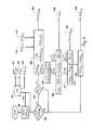
- FIG. 2is a block diagram of the electronics contained within the housing of FIG. 1 .
- FIG. 3is a feedback control loop diagram demonstrating the operation of an observer in accordance with a preferred embodiment of the present invention.
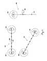
- FIG. 4is a diagram of an example water body including three ski courses.
- FIG. 5is a flow diagram disclosing a method that an observer in accordance with a preferred embodiment of the present invention may use to determine observed velocity and observed position.
- FIG. 6is a flow diagram disclosing a method for automatically detecting a previously-mapped course.
- FIG. 7is a flow diagram disclosing a method of detecting and reporting the time at which a plurality of events is detected.
- FIG. 8is a flow diagram disclosing a method by which a user interactively “maps” a desired water course, and by which the present invention stores the mapped water course into non-volatile memory.
- FIG. 9is an example of a competitive slalom ski course.
- the present inventionrelates generally to electronic event detectors and more specifically to electronic event detectors for use with power boats.
- the event detector 100 of the present inventionincludes a housing 102 for housing the electronics of the invent detector an accelerometer 106 and a GPS 104 .
- GPS 104is preferably a unit separate from housing 102 , e.g. a GARMIN® GPS 18-5 Hz.
- Electronic housing 102includes a display 108 and interface buttons 110 .
- the display 108is preferably made out of moldable materials such as plastic, aluminum, glass, and the like, with a clear glass or plastic cover.
- the housingis adapted to be waterproof to prevent damage to the electronics when in use.
- the display 108may be a commercially available LCD display that is capable of displaying numbers or letters and information related to the event.
- User interface buttons 110are actuators attached to the electronics covered in a rubberized membrane that allows buttons to remain waterproof during their actuation.
- the LCD display interface buttons 110 and glass coverare attached to an insulated housing 102 via e.g., screws, friction fit, adhesive, or the like inside the housing 102 are electronics, to be described below, that perform the functions of the device.
- the electronics of the event locator device 100includes microprocessor 200 , non-volatile storage 202 , GPS interface 204 , Clock 206 , speaker 208 , power device 210 , user input interface 214 , accelerometer 216 , and analog-to-digital converter 218 .
- Microprocessor 200is the “brains” of the invention and performs location calculations and timing data for output to a user.
- microprocessor 200is capable of being externally programmed.
- Volatile storage 202is connected to microprocessor 200 and stores event data such as map information, location information, and timing information for the microprocessor's calculations.
- Clock device 206provides time data to the microprocessor 200 which can be displayed to a user.
- GPS interface 204interfaces with the GPS system which provides location data to the microprocessor 200 .
- Accelerometer 216generates an acceleration signal and provides the same to the microprocessor 2000 .
- AC/DC converterconverts the signal from the accelerometer to a digital signal for input into the microcontroller 200 .
- User input interface 214is connected to the microprocessor and allows the user to program certain device settings into the non-volatile storage 202 such as map information, desired speed, and the like.
- Display 212interacts with microprocessor to display event data speed, location and time information.
- Power supply 210provides power to microcontroller and all of the associated electronics.
- FIG. 3contemplates a scenario where course mapping information is already saved in memory and accessible by the microprocessor.
- the accelerometerreceives a signal from the boat indicative of the boat's acceleration and inputs this signal to a microprocessor.
- the microprocessorconverts the acceleration value into a velocity value in step 15 and in step 16 receives both the velocity information from the accelerometer and the velocity data from the GPS.
- the velocity from a GPSis not updated continuously, and the velocity information from the accelerometer is used to provide resolution to the velocity information from the GPS system in step 17 .
- An observed velocityis output at step 17 , and in step 70 the velocity information and direction information obtained from the GPS system is used to calculate a latitude and longitude value for the accelerometer.
- latitude and longitude information from the GPS systemis compared to latitude and longitude information from the accelerometer.
- the latitude and longitude information from the accelerometeris then used to attenuate the GPS signal.
- the microprocessorthen outputs a latitude and longitude observed signal, which is used in reference to map data input by the user at the start of the process.
- the microprocessoroutputs a sound signal to speaker 208 and a display signal to user display 108 .
- the accelerometer 216 , analog-to-digital converter 218 , computing device 200 , GPS unit 204 , memory 221 and clock 206comprise the elements of an observer 222 .
- the observer 222is adapted to act both as a velocity observer (in which it outputs an observed velocity) and as a position observer (in which it outputs an observed position).
- an accelerometeracts as the primary source of data for computing displacements over time, with periodic updates from the GPS provided to account for drift in the accelerometer. But it will be appreciated by those skilled in the art that there are many other methods available for performing this task.
- over-water velocitymay be measured directly by means of a transducer such as a paddle wheel or a pitot tube, and those measurements may or may not be corrected with GPS inputs.
- a transducersuch as a paddle wheel or a pitot tube
- GPS inputsIn the case of direct velocity measurement, only a single integration with respect to time is needed to compute a new position.
- GPS technologybecomes more accurate and as new data are available at a higher frequency, it is conceivable that a GPS unit will provide the sole velocity and position inputs.
- Other configurations for measuring velocity and positionwill be apparent to those of ordinary skill in the art, and it is intended for this patent to encompass such additional configurations.
- FIG. 5discloses the functioning of a preferred embodiment of an observer 222 .
- a GPS signalis received from the GPS device 204 .
- GPS device 204provides a GPS position 513 , a GPS velocity 512 , and a GPS direction 511 .
- Step 501uses the GPS position as its initial starting position.
- Step 502there is a check to see if a new GPS position has been received. If a new GPS position has been received, in Step 503 it is checked to see if the GPS position is a valid GPS position. Step 503 compensates for the potential of invalid GPS signals such as occasionally occur in GPS devices known in the art.
- the observed position 509is set to a value of the accelerometer corrected by the difference between the last observed position and the GPS position 513 .
- a constant 515is provided such as is calculated to provide the appropriate weight to the GPS measurement. For example, if constant 515 is set to one, then the GPS position is afforded its full weight. If constant 515 is set to a value less than one, the GPS is provided less weight, and it if it set to a value greater than one, the GPS is provided more weight. This constant is selected in accordance with the relative accuracies of the GPS and accelerometer such that for a more accurate GPS device, greater weight can be given to the GPS value and for a less accurate GPS device, less weight can be given to the GPS value. The result of this calculation is an observed position 509 .
- an alternative devicestarting at step 505 , which includes an accelerometer 316 .
- the accelerometerprovides a measured acceleration which is converted to a binary value in analog-to-digital converter 218 . It is then useful for being compared to digital values provided by the GPS device 204 .
- an observed velocityis computed. The velocity is computed by first taking the last observed velocity 510 and the velocity provided by the GPS 512 . This difference is adjusted by a velocity constant 517 . As with position constant 515 , velocity constant 517 is selected to compensate for the relative accuracy of the GPS device.
- an accelerometer-computed position 514is calculated. This position is computed by taking the integral of the velocity vector with respect to time. The displacement calculated thereby is adjusted to the direction signal provided by the GPS.
- This GPS correction stepis used in the preferred embodiment because, in the interest of simplicity, the three-accelerometer is used only to compute acceleration along the single axis of the length of the boat. The result is accelerometer-computed position 514 .
- the usefulness of accelerometer-computed position 514is that it can be calculated at a frequency of approximately 1,000 hertz.
- the observed positionis provided by the change in position as calculated by the accelerometer with no further input from the GPS device.
- an observed position 509there is provided from the observer an observed position 509 as well as an observed velocity 510 .
- FIG. 8discloses a method of using a watercraft equipped with a position and velocity observer, such as is described in FIG. 5 , to map a competitive water course.
- step 801there is initial determination of the position and velocity of the watercraft as provided by the observed velocity 510 and the observed position 509 .
- step 802there is a check to see whether there has been a user input from a map button 214 . If no user input is provided, then the position observer continuously updates the position and velocity of the watercraft. Once there has been a user input at step 803 , the current observed position 509 and the current heading are stored in non-volatile storage 202 .
- step 805there is provided a step of checking to see if it is desired to map another point. If another point is to be mapped, then there is a return to step 801 and the method is repeated until, at step 805 , there is no further point to mapped.
- the devicemay calculate a number of predetermined intermediate points in between the points mapped and stored in step 803 . These intermediate points are also stored in non-volatile storage 202 .
- FIG. 6there is disclosed a method of automatically detecting a course that has been mapped in accordance with the method of FIG. 8 .
- step 601there is initial determination of position and velocity provided by observed position 509 and observed velocity 510 .
- step 602compare the observed position 509 to a predetermined position as mapped in accordance with the method of FIG. 8 .
- This mapped positionis provided from non-volatile storage 202 .
- 603there is a determination of which of a plurality of mapped courses as mapped in accordance with the method of FIG. 8 is the closest to the present observed position 509 .
- step 604there is a check to see whether the watercraft is inside the lockout region of the closest water course. If the craft is within the lockout region, then there is also a check to see whether the craft is approaching from outside the course and is proceeding in the right direction along the center line of the course. If these criteria are not met, then continue looking for entrance into a course. If the criteria are met, then, in step 606 , check to see whether the craft has crossed the plane of the entry gate of the course. If it has not, then return to step 602 , continuing looking for entry to a course. If the criteria are met, then the craft has entered a mapped course and the course timing algorithm will automatically begin in step 607 . This provides an observed position at the entry point 608 .
- FIG. 7there is disclosed a method for computing total time and intermediate times through a competitive water course.
- the time at the entry pointis recorded in temporary memory 221 .
- an observed position 509is provided and this provides the present position of the watercraft.
- a plurality of points of interestare stored in non-volatile storage 202 .
- a point of interestis provided and there is a check to see if the current observed position 509 exceeds the position of the point of interest. If the present position 509 does not exceed the position of the point of interest, then the loop is continued until the present observed position exceeds the position of the point of interest.
- step 704the present observed time 709 is recorded into temporary memory 221 and, in step 705 , the current observed time 709 is displayed on user display 212 .
- step 706there is provided an ideal time 710 .
- An error time 711is computed as the difference between the ideal time 710 and the observed time 709 .
- the error time 711is also stored in temporary storage 221 and displayed on user display 212 .
- step 704when a point of interest is reached, there is also provided an audible signal through a speaker 208 to provide an audible indication to the user that this point has been passed.
- steps 704 , 705 , 706 and 708are completed, then in step 707 there is a check to see if this is the last point of interest. If it is not, then there is a return to step 702 . If this is the last point of interest, the process ends.
- the inertia measurement device (accelerometer) 216measures the actual acceleration a a of a watercraft 50 and the GPS device 204 measures the actual velocity v a and position of the same watercraft 50 .
- the output from the accelerometer a Accis input into a first step 15 that coverts a Acc to velocity V Acc .
- the output from first step 15 v Acc and the GPS output v GPSare input to a second step 17 .
- the output from a second step 17 v OBS and the output (Dir GPS ) indicating course or direction of travel from the GPS device 204are input into a third step 70 to derive inertial-based estimates of the latitude (Lat Acc ) and longitude (Long Acc of the watercraft 50 .
- Direct GPS measurements of latitude (Lat GPS ) and longitude (Long GPS ) and the outputs from the third step 70are input in a fourth step 80 to correct inertial-based estimates of the latitude (Lat Acc ) and longitude (Long Acc ) of the watercraft 50 to account for any inaccuracies due to drift or acceleration sensor inaccuracies.
- Lat OBS and Long OBScan then be used to allow the boat driver to record via a user interface the absolute latitude and longitude position coordinates of a course to be saved into a permanent non-volatile memory. Coordinates can be recorded either by direct numerical entry of measured coordinates, or by snapshotting course coordinates as the boat is maneuvering through the course to be mapped.
- the drivercan identify course reference points via a user interface (not shown) or button press as the boat passes the point to be mapped. Since all courses of interest are laid out in straight lines, mapping of two known points in a course is sufficient to fully define the locations of all points of interest in a course and it's direction relative to earth latitude and longitude coordinates. All future passages of the towboat within a specified distance of selected course coordinates as measured by Lat OBS and Long OBS can then be detected and used to initiate timing measurements of the towboat through the mapped course.
- FIG. 9discloses a competitive slalom ski course. This is the type of course on which an embodiment of the present invention may be used.
- an entry gate 901which can be characterized by a precise global coordinate specified in latitude and longitude.
- the opposite end point of the courseis exit gate 905 , which may also be characterized as a latitude and longitude. Because the course lies along a substantially straight line, the locations of all points of interest along the course can be found given the positions of the two end points.
- a course centerline 906lies along a substantially straight line and is slightly larger than the width of a water craft. The centerline is defined by boat buoys 904 , which the water craft must stay in between.
- ski buoys 902which the skier must ski around during the passage of the course, in an alternating pattern as shown by the ski path 903 .
- the skiermust pass between the buoys defining first break point 907 before proceeding along ski path 903 .
- a second break point 908At the end of the course is a second break point 908 .
- the skiermust ski between the two buoys defining second break point 908 after passing around the last buoy 902 .
- intermediate points 904In between these points are six intermediate points 904 , each defined by a pair of buoys, which are positioned to be substantially collinear with the ski buoys 902 .
- the entry gate 901 , exit gate 905 , break points 907 and 908 and intermediate buoys 904are all points of interest whose passage may need to be detected.
- the time at which the boat 50 passes these pointsmay be used to determine whether a run is valid, according to whether the time is within an allowable margin of error. Because these points are defined according to precisely-surveyed distances, their locations can be detected by a substantially accurate observer (such as is provided by the preferred embodiment of the present invention) given only the location of the two end points. So the mapping course-mapping method described in FIG. 8 provides the observer with sufficient information to determine when a point of interest has been passed in accordance with the method of FIG. 7 .
- the location of the coursecan be stored in a permanent storage medium 202 such as a disk drive or flash memory. Further qualification of valid entry to a course can then be carried out based on GPS direction measurements so that timing measurements are only made when the towboat enters a mapped course while traveling along the known direction of the course centerline. Further, any deviations of the tow boat from the center line of the course can be detected and factored geometrically into the measurement of displacement down the centerline of the course so that errors in timing measurement due to driver steering error can be compensated for.
- a permanent storage medium 202such as a disk drive or flash memory.
- FIG. 4discloses a water course with a plurality of competitive ski courses. There is disclosed a first slalom course 401 , a second slalom course 402 and a jump course 403 .
- First slalom course 401has entry and exit thresholds 405 .
- Second slalom course 402has entry and exit thresholds 406 .
- the slalom coursesmay be traversed in either direction through entry and exit thresholds 405 and 406 .
- a jump course 403may be entered only through entry threshold 411 because ski jump 409 is unidirectional.
- a usermay approach a course, for example first slalom course 401 .
- a coursefor example first slalom course 401 .
- the userUpon entering the entry threshold 405 in the direction of the course centerline 408 , the user will press a button whereby the computing device is alerted of the location of the entry/exit threshold. The user then proceeds along course centerline 408 and presses a button again at the opposite entry/exit threshold 405 .
- the computing devicealso interfaces with a permanent storage medium.
- This storage mediumcontains the desired locations of intermediate buoys 407 , which are located at pre-determined distances from the entry/exit buoys. “This process” allows the computing device to learn the exact location of first slalom course 401 . “The process” can then be repeated to allow the computing device to learn the locations of second slalom course 402 and jump course 409 .
- the devicewill detect which of the mapped courses is closest to its present position.
- the devicemay also selectively detect only courses of a specific type (jump or slalom) depending on its current mode of operation. If the device then determines it is within a lockout regions 404 , it will check to see if the boat is approaching from outside the entry/exit threshold and in the correct direction along the course centerline. If these criteria are met, then the device will calculate the time of the closest approach to the plane of the entry gate. At that time it will begin timing the path without any intervention from the user.
- the devicemay provide an audible or visual indication of the passing of each intermediate buoy 407 . It may also provide intermediate times at the passing of each intermediate buoy 407 . Finally, it will calculate the time at which boat 50 passes through the opposite entry/exit threshold 405 .
- the devicecan automatically time a pass through a memorized course without any further intervention from the user.
- a driver scorecan also be provided based on the degree of this error which can be used to rate driver performance and confirm accuracy of the boat path through the course, which is also a criterion used in judging whether a competitive pass is valid.
- Any boat speed or engine torque modification requirements which may depend on position in the coursecan be triggered based on Lat OBS and Long OBS relative to the mapped course location.
- the device of the inventionis one of the category of commonly understood instruments that measures an object's acceleration.
- the velocity of on objectcan be calculated by integrating the acceleration of an object over time.
- the position of an object relative to a known starting pointcan be calculated by integrating the velocity of an object over time.
- a GPS deviceis one of the category of commonly understood instruments that use satellites to determine the substantially precise global position and velocity of an object. Such position and velocity measurements can be used in conjunction with timers to determine an object's instantaneous velocity and average velocity between two points, along with its absolute position at any point in time.
- a comparatoris any analog or digital electrical, electronic, mechanical, hydraulic, or fluidic device capable of determining the sum of or difference between two input parameters, or the value of an input relative to a predetermined standard.
- An algorithmis any analog or digital electrical, electronic, mechanical, hydraulic, or fluidic device capable of performing a computational process. The algorithms disclosed herein can be performed on any number of computing devices commonly called microprocessors or microcontrollers, examples of which include the Motorola® MPC555 and the Texas Instruments® TMS320.
- inventions of the systemcould include automated steering of the boat down the centerline of the course making use of course location information stored as described in 0014 thru 0016 above.
- the present inventionmay be included as part of an electronic closed-loop feedback system that controls the actual angular velocity ⁇ a of a boat propeller, and, indirectly, the actual over land velocity V a of the watercraft propelled by that propeller.
- Another embodimentallows the apparatus to track the position of a skier behind the watercraft as he/she traverses the course. This can be achieved by mounting a GPS antenna somewhere on or near the body of the skier and capturing these data concurrently with data from a tow boat mounted antenna. Such GPS antennae can be either wired or wirelessly connected to the main apparatus.
- the present inventionprovides an apparatus for tracking the position and velocity of a watercraft through a prescribed course without the need for measurement aids such as magnets built into the course infrastructure. It is understood that the forms of the invention shown and described in the detailed description and the drawings are to be taken merely as presently preferred examples and that the invention is limited only by the language of the claims. The drawings and detailed description presented herein are not intended to limit the invention to the particular embodiments disclosed. While the present invention has been described in terms of one preferred embodiment and a few variations thereof, it will be apparent to those skilled in the art that form and detail modifications can be made to that embodiment without departing from the spirit or scope of the invention.
Landscapes
- Engineering & Computer Science (AREA)
- Radar, Positioning & Navigation (AREA)
- Remote Sensing (AREA)
- Automation & Control Theory (AREA)
- General Physics & Mathematics (AREA)
- Physics & Mathematics (AREA)
- Chemical & Material Sciences (AREA)
- Ocean & Marine Engineering (AREA)
- Mechanical Engineering (AREA)
- Combustion & Propulsion (AREA)
- Aviation & Aerospace Engineering (AREA)
- Position Fixing By Use Of Radio Waves (AREA)
- Navigation (AREA)
Abstract
Description
Claims (20)
Priority Applications (1)
| Application Number | Priority Date | Filing Date | Title |
|---|---|---|---|
| US13/016,187US9092033B1 (en) | 2005-02-11 | 2011-01-28 | Event sensor |
Applications Claiming Priority (8)
| Application Number | Priority Date | Filing Date | Title |
|---|---|---|---|
| US11/056,848US7229330B2 (en) | 2004-02-11 | 2005-02-11 | Watercraft speed control device |
| US11/811,606US7485021B2 (en) | 2004-02-11 | 2007-06-11 | Watercraft speed control device |
| US11/811,605US7491104B2 (en) | 2004-02-11 | 2007-06-11 | Watercraft speed control device |
| US11/811,616US7494393B2 (en) | 2004-02-11 | 2007-06-11 | Watercraft speed control device |
| US11/811,604US7465203B2 (en) | 2004-02-11 | 2007-06-11 | Watercraft speed control device |
| US11/811,617US7494394B2 (en) | 2004-02-11 | 2007-06-11 | Watercraft speed control device |
| US11/903,208US20080243321A1 (en) | 2005-02-11 | 2007-09-19 | Event sensor |
| US13/016,187US9092033B1 (en) | 2005-02-11 | 2011-01-28 | Event sensor |
Related Parent Applications (1)
| Application Number | Title | Priority Date | Filing Date |
|---|---|---|---|
| US11/903,208DivisionUS20080243321A1 (en) | 2004-02-11 | 2007-09-19 | Event sensor |
Publications (1)
| Publication Number | Publication Date |
|---|---|
| US9092033B1true US9092033B1 (en) | 2015-07-28 |
Family
ID=53638409
Family Applications (5)
| Application Number | Title | Priority Date | Filing Date |
|---|---|---|---|
| US11/903,208AbandonedUS20080243321A1 (en) | 2004-02-11 | 2007-09-19 | Event sensor |
| US13/016,153Active2026-01-26US9098083B1 (en) | 2005-02-11 | 2011-01-28 | Event sensor |
| US13/016,229Active2025-11-28US8983768B1 (en) | 2005-02-11 | 2011-01-28 | Event sensor |
| US13/016,098Expired - LifetimeUS9068838B1 (en) | 2005-02-11 | 2011-01-28 | Event sensor |
| US13/016,187Active2026-09-13US9092033B1 (en) | 2005-02-11 | 2011-01-28 | Event sensor |
Family Applications Before (4)
| Application Number | Title | Priority Date | Filing Date |
|---|---|---|---|
| US11/903,208AbandonedUS20080243321A1 (en) | 2004-02-11 | 2007-09-19 | Event sensor |
| US13/016,153Active2026-01-26US9098083B1 (en) | 2005-02-11 | 2011-01-28 | Event sensor |
| US13/016,229Active2025-11-28US8983768B1 (en) | 2005-02-11 | 2011-01-28 | Event sensor |
| US13/016,098Expired - LifetimeUS9068838B1 (en) | 2005-02-11 | 2011-01-28 | Event sensor |
Country Status (1)
| Country | Link |
|---|---|
| US (5) | US20080243321A1 (en) |
Cited By (1)
| Publication number | Priority date | Publication date | Assignee | Title |
|---|---|---|---|---|
| CN110178165A (en)* | 2016-12-30 | 2019-08-27 | 邦迪克斯商用车系统有限责任公司 | Fleet vehicle sorting in team certainly |
Families Citing this family (44)
| Publication number | Priority date | Publication date | Assignee | Title |
|---|---|---|---|---|
| US20080243321A1 (en)* | 2005-02-11 | 2008-10-02 | Econtrols, Inc. | Event sensor |
| US8169587B2 (en)* | 2007-08-16 | 2012-05-01 | Apple Inc. | Methods and systems for strengthening LCD modules |
| US8673163B2 (en) | 2008-06-27 | 2014-03-18 | Apple Inc. | Method for fabricating thin sheets of glass |
| US7810355B2 (en) | 2008-06-30 | 2010-10-12 | Apple Inc. | Full perimeter chemical strengthening of substrates |
| US20100087110A1 (en)* | 2008-10-03 | 2010-04-08 | Berg Christopher P J | Automatic Deploying and Positioning Slalom Water Ski Course |
| US9322918B2 (en)* | 2009-02-22 | 2016-04-26 | Trimble Navigation Limited | GNSS surveying methods and apparatus |
| CN102388003B (en) | 2009-03-02 | 2014-11-19 | 苹果公司 | Technology for Strengthening Glass Covers for Portable Electronic Devices |
| US8549882B2 (en)* | 2009-09-30 | 2013-10-08 | Apple Inc. | Pre-processing techniques to produce complex edges using a glass slumping process |
| US9778685B2 (en) | 2011-05-04 | 2017-10-03 | Apple Inc. | Housing for portable electronic device with reduced border region |
| US9213451B2 (en) | 2010-06-04 | 2015-12-15 | Apple Inc. | Thin glass for touch panel sensors and methods therefor |
| US9207528B2 (en) | 2010-06-04 | 2015-12-08 | Apple Inc. | Thin sheet glass processing |
| US8923693B2 (en)* | 2010-07-30 | 2014-12-30 | Apple Inc. | Electronic device having selectively strengthened cover glass |
| US10189743B2 (en)* | 2010-08-18 | 2019-01-29 | Apple Inc. | Enhanced strengthening of glass |
| JP5119504B2 (en)* | 2010-08-24 | 2013-01-16 | Necビッグローブ株式会社 | Pass determination device, pass determination method, program |
| US8873028B2 (en) | 2010-08-26 | 2014-10-28 | Apple Inc. | Non-destructive stress profile determination in chemically tempered glass |
| US8824140B2 (en) | 2010-09-17 | 2014-09-02 | Apple Inc. | Glass enclosure |
| US9725359B2 (en) | 2011-03-16 | 2017-08-08 | Apple Inc. | Electronic device having selectively strengthened glass |
| US10781135B2 (en) | 2011-03-16 | 2020-09-22 | Apple Inc. | Strengthening variable thickness glass |
| EP2514652A1 (en) | 2011-04-14 | 2012-10-24 | Thomas Rastija | Method and device for limiting the speed of a motor vehicle |
| US9128666B2 (en) | 2011-05-04 | 2015-09-08 | Apple Inc. | Housing for portable electronic device with reduced border region |
| US9944554B2 (en) | 2011-09-15 | 2018-04-17 | Apple Inc. | Perforated mother sheet for partial edge chemical strengthening and method therefor |
| US9516149B2 (en) | 2011-09-29 | 2016-12-06 | Apple Inc. | Multi-layer transparent structures for electronic device housings |
| US10144669B2 (en) | 2011-11-21 | 2018-12-04 | Apple Inc. | Self-optimizing chemical strengthening bath for glass |
| US10133156B2 (en) | 2012-01-10 | 2018-11-20 | Apple Inc. | Fused opaque and clear glass for camera or display window |
| US8684613B2 (en) | 2012-01-10 | 2014-04-01 | Apple Inc. | Integrated camera window |
| US8773848B2 (en) | 2012-01-25 | 2014-07-08 | Apple Inc. | Fused glass device housings |
| US10360636B1 (en) | 2012-08-01 | 2019-07-23 | Allstate Insurance Company | System for capturing passenger and trip data for a taxi vehicle |
| US9946302B2 (en) | 2012-09-19 | 2018-04-17 | Apple Inc. | Exposed glass article with inner recessed area for portable electronic device housing |
| US9459661B2 (en) | 2013-06-19 | 2016-10-04 | Apple Inc. | Camouflaged openings in electronic device housings |
| US9886062B2 (en) | 2014-02-28 | 2018-02-06 | Apple Inc. | Exposed glass article with enhanced stiffness for portable electronic device housing |
| DE102014104572B4 (en)* | 2014-04-01 | 2017-11-02 | Deutsches Zentrum für Luft- und Raumfahrt e.V. | Speedometer |
| US11307042B2 (en) | 2015-09-24 | 2022-04-19 | Allstate Insurance Company | Three-dimensional risk maps |
| WO2017089643A1 (en)* | 2015-11-26 | 2017-06-01 | Wärtsilä Finland Oy | Marine vessel performance diagnostics |
| US10699347B1 (en) | 2016-02-24 | 2020-06-30 | Allstate Insurance Company | Polynomial risk maps |
| US10597118B2 (en) | 2016-09-12 | 2020-03-24 | Kai Concepts, LLC | Watercraft device with hydrofoil and electric propeller system |
| US10264111B2 (en) | 2016-10-04 | 2019-04-16 | Allstate Solutions Private Limited | Mobile device communication access and hands-free device activation |
| US9979813B2 (en) | 2016-10-04 | 2018-05-22 | Allstate Solutions Private Limited | Mobile device communication access and hands-free device activation |
| US11295218B2 (en) | 2016-10-17 | 2022-04-05 | Allstate Solutions Private Limited | Partitioning sensor based data to generate driving pattern map |
| US11852487B2 (en)* | 2020-02-05 | 2023-12-26 | Nothern Flow Inc. | Methods and systems to enable travel on a waterway |
| US11897583B2 (en) | 2020-04-22 | 2024-02-13 | Kai Concepts, LLC | Watercraft device with hydrofoil and electric propulsion system |
| US10946939B1 (en) | 2020-04-22 | 2021-03-16 | Kai Concepts, LLC | Watercraft having a waterproof container and a waterproof electrical connector |
| US12246811B2 (en) | 2020-04-22 | 2025-03-11 | Kai Concepts, LLC | Watercraft device with a handheld controller |
| US11485457B1 (en) | 2021-06-14 | 2022-11-01 | Kai Concepts, LLC | Hydrojet propulsion system |
| US11878775B2 (en) | 2021-07-13 | 2024-01-23 | Kai Concepts, LLC | Leash system and methods of use |
Citations (105)
| Publication number | Priority date | Publication date | Assignee | Title |
|---|---|---|---|---|
| US3748466A (en) | 1971-06-14 | 1973-07-24 | Gen Signal Corp | Vehicle control system |
| US4392122A (en)* | 1980-06-26 | 1983-07-05 | Hocken Redvers A | Magnetically triggered on-board elapsed time indicator |
| US4422423A (en) | 1979-04-24 | 1983-12-27 | Kabushiki Kaisha Toyota Chuo Kenyusho | Jet control type carburetor |
| US4939661A (en) | 1988-09-09 | 1990-07-03 | World Research Institute For Science And Technology | Apparatus for a video marine navigation plotter with electronic charting and methods for use therein |
| US5074810A (en) | 1990-06-29 | 1991-12-24 | Lakeland Engineering Corporation | Automatic speed control system for boats |
| US5110310A (en) | 1991-04-25 | 1992-05-05 | Lakeland Engineering Corporation | Automatic speed control system for boats |
| US5142473A (en) | 1988-08-12 | 1992-08-25 | Davis Dale R | Speed, acceleration, and trim control system for power boats |
| US5276660A (en)* | 1992-05-29 | 1994-01-04 | Lee Richard D | Competition waterskier timing system |
| US5355855A (en) | 1993-12-27 | 1994-10-18 | Hitachi America, Ltd. | Integrated feed forward air/fuel ratio sensor for gaseous fuel engines |
| US5367999A (en) | 1993-04-15 | 1994-11-29 | Mesa Environmental Ventures Limited Partnership | Method and system for improved fuel system performance of a gaseous fuel engine |
| US5369589A (en)* | 1993-09-15 | 1994-11-29 | Trimble Navigation Limited | Plural information display for navigation |
| US5404341A (en)* | 1992-11-20 | 1995-04-04 | Seiko Instruments Inc. | Time measurement apparatus |
| US5416712A (en) | 1993-05-28 | 1995-05-16 | Trimble Navigation Limited | Position and velocity estimation system for adaptive weighting of GPS and dead-reckoning information |
| US5458104A (en) | 1994-01-14 | 1995-10-17 | Walbro Corporation | Demand fuel pressure regulator |
| US5694337A (en)* | 1995-04-03 | 1997-12-02 | Macken; John A. | Water ski performance analysis method and apparatus |
| US5700171A (en) | 1995-10-27 | 1997-12-23 | Perfect Pass Control Systems Incorporation | Speed control system |
| US5731788A (en)* | 1995-01-11 | 1998-03-24 | Trimble Navigation | Global positioning and communications system and method for race and start line management |
| US5808671A (en) | 1994-11-24 | 1998-09-15 | Augat Photon Systems Inc. | Apparatus and method for remote monitoring of video signals |
| US5828987A (en) | 1995-08-28 | 1998-10-27 | Data Tec Co., Ltd. | Movement detecting device |
| US5828979A (en) | 1994-09-01 | 1998-10-27 | Harris Corporation | Automatic train control system and method |
| US5848373A (en) | 1994-06-24 | 1998-12-08 | Delorme Publishing Company | Computer aided map location system |
| JPH1153700A (en)* | 1997-07-30 | 1999-02-26 | Mitsubishi Electric Corp | Automatic ship steering system |
| US5884213A (en)* | 1996-03-22 | 1999-03-16 | Johnson Worldwide Asociates, Inc. | System for controlling navigation of a fishing boat |
| US5904131A (en) | 1995-12-28 | 1999-05-18 | Cummins Engine Company, Inc. | Internal combustion engine with air/fuel ratio control |
| US5905713A (en) | 1996-04-15 | 1999-05-18 | Hughes Electronics Corporation | Method and apparatus for analyzing digital multi-program transmission packet streams |
| US6041762A (en) | 1996-08-16 | 2000-03-28 | Impco Technologies, Inc. | Control module for natural gas fuel supply for a vehicle |
| US6076042A (en) | 1996-04-29 | 2000-06-13 | Sun Microsystems, Inc. | Altitude sparse aircraft display |
| US6131552A (en) | 1998-08-14 | 2000-10-17 | Dana Corporation | Fuel control system for a gas-operated engine |
| US6157297A (en) | 1997-06-20 | 2000-12-05 | Yamaha Hatsudoki Kabushiki Kaisha | Display for vehicle navigational system |
| US6169495B1 (en) | 1997-10-23 | 2001-01-02 | Toyota Jidosha Kabushiki Kaisha | Vehicle traffic control system |
| US6176224B1 (en) | 1998-03-30 | 2001-01-23 | Caterpillar Inc. | Method of operating an internal combustion engine which uses a low energy gaseous fuel |
| WO2001029512A1 (en) | 1999-10-19 | 2001-04-26 | Jfdi Engineering Limited | Improvements in or relating to vehicle navigation |
| US6227918B1 (en) | 2000-01-05 | 2001-05-08 | Mark E. Wharton | System for determining apparent slip and angle of attack |
| US6259381B1 (en) | 1995-11-09 | 2001-07-10 | David A Small | Method of triggering an event |
| US6267105B1 (en) | 1998-06-12 | 2001-07-31 | Bruno Bertossi | Electronic pressure reducer for liquid petroleum gasses |
| US6273771B1 (en) | 2000-03-17 | 2001-08-14 | Brunswick Corporation | Control system for a marine vessel |
| US6283240B1 (en) | 1998-09-02 | 2001-09-04 | Rover Group Limited | Vehicle |
| US6289278B1 (en) | 1998-02-27 | 2001-09-11 | Hitachi, Ltd. | Vehicle position information displaying apparatus and method |
| US6289277B1 (en) | 1999-10-07 | 2001-09-11 | Honeywell International Inc. | Interfaces for planning vehicle routes |
| US20010032236A1 (en) | 1999-12-09 | 2001-10-18 | Ching-Fang Lin | Portable multi-tracking method and system |
| US6312301B1 (en)* | 2000-09-15 | 2001-11-06 | Lawrence R. Kennedy | Virtual slalom course |
| US20010055063A1 (en) | 2000-05-26 | 2001-12-27 | Honda Giken Kogyo Kabushiki Kaisha | Position detection apparatus, position detection method and position detection program |
| US6340005B1 (en) | 2000-04-18 | 2002-01-22 | Rem Technology, Inc. | Air-fuel control system |
| US20020022927A1 (en) | 1993-08-11 | 2002-02-21 | Lemelson Jerome H. | GPS vehicle collision avoidance warning and control system and method |
| US6353781B1 (en) | 2000-07-05 | 2002-03-05 | Nordskog Publishing, Inc. | GPS controlled marine speedometer unit with multiple operational modes |
| US6389333B1 (en) | 1997-07-09 | 2002-05-14 | Massachusetts Institute Of Technology | Integrated flight information and control system |
| US6401446B1 (en) | 2000-06-23 | 2002-06-11 | Hamilton Sundstrand Corporation | Valve apparatus for providing shutoff and overspeed protection in a gas turbine fuel system |
| US6456910B1 (en) | 2000-11-21 | 2002-09-24 | John Andrew Roe | Light Guided autopilot |
| US6485341B1 (en) | 2001-04-06 | 2002-11-26 | Brunswick Corporation | Method for controlling the average speed of a vehicle |
| US6507785B1 (en) | 2001-09-21 | 2003-01-14 | General Motors Corportion | Method and system for detecting and correcting off route navigation for server based route guidance systems |
| US6517396B1 (en) | 2000-07-03 | 2003-02-11 | Stephen W. Into | Boat speed control |
| US20030036814A1 (en)* | 2001-08-14 | 2003-02-20 | Middleton Paul Lawrence | Slalom water-ski training and monitoring system for on-water use |
| US20030050754A1 (en) | 2002-07-29 | 2003-03-13 | Edwards Daniel L. | Mapping patterns of movement based on the aggregation of spatial information contained in wireless transmissions |
| US20030060973A1 (en) | 2001-05-31 | 2003-03-27 | Infomove, Inc. | Method and system for distributed navigation and automated guidance |
| US6573486B1 (en) | 2002-02-22 | 2003-06-03 | Northrop Grumman Corporation | Projectile guidance with accelerometers and a GPS receiver |
| US6577932B1 (en)* | 1998-09-16 | 2003-06-10 | Wärtsilä Propulsion Netherlands B.V. | System for controlling a vessel |
| US20030135327A1 (en) | 2002-01-11 | 2003-07-17 | Seymour Levine | Low cost inertial navigator |
| US20030158665A1 (en) | 1999-11-29 | 2003-08-21 | Mccall Hiram | Vehicle self-carried positioning method and system thereof |
| US6643580B1 (en)* | 1998-10-16 | 2003-11-04 | Universal Avionics Systems Corporation | Flight plan intent alert system and method |
| US6701905B1 (en) | 2003-04-30 | 2004-03-09 | Delphi Technologies, Inc. | Fuel pressure control method for an alternate-fuel engine |
| US20040056779A1 (en) | 2002-07-01 | 2004-03-25 | Rast Rodger H. | Transportation signaling device |
| US6722302B2 (en) | 2000-09-18 | 2004-04-20 | Kawasaki Jukogyo Kabushiki Kaisha | Jet-propulsion watercraft |
| US6748325B1 (en) | 2001-12-07 | 2004-06-08 | Iwao Fujisaki | Navigation system |
| US6763226B1 (en) | 2002-07-31 | 2004-07-13 | Computer Science Central, Inc. | Multifunctional world wide walkie talkie, a tri-frequency cellular-satellite wireless instant messenger computer and network for establishing global wireless volp quality of service (qos) communications, unified messaging, and video conferencing via the internet |
| US20040150557A1 (en) | 2003-01-21 | 2004-08-05 | Ford Thomas John | Inertial GPS navigation system with modified kalman filter |
| US6779752B1 (en) | 2003-03-25 | 2004-08-24 | Northrop Grumman Corporation | Projectile guidance with accelerometers and a GPS receiver |
| US20040193334A1 (en) | 2003-03-27 | 2004-09-30 | Carl-Olof Carlsson | Waypoint navigation |
| US6826478B2 (en)* | 2002-04-12 | 2004-11-30 | Ensco, Inc. | Inertial navigation system for mobile objects with constraints |
| US6845321B1 (en) | 2003-06-30 | 2005-01-18 | Michael Lester Kerns | Method and system for providing narrative information to a traveler |
| US6864807B2 (en) | 2001-07-09 | 2005-03-08 | Nissan Motor Co., Ltd. | Information display system for vehicle |
| US20050075782A1 (en) | 2002-02-21 | 2005-04-07 | Torgunrud John Arnold | Vehicle and traffic information processing system |
| US6884128B2 (en) | 2002-10-23 | 2005-04-26 | Yamaha Marine Kabushiki Kaisha | Speed control system and method for watercraft |
| US6904364B2 (en) | 2002-04-02 | 2005-06-07 | William S. Randazzo | Navcell pier to pier GPS |
| US20050176312A1 (en) | 2004-02-11 | 2005-08-11 | Econtrols, Inc. | Watercraft speed control device |
| US20050191916A1 (en)* | 2004-03-01 | 2005-09-01 | Mark Bozicevic | System and device for improving the performance of a water skier in a slalom course |
| US20050222933A1 (en) | 2002-05-21 | 2005-10-06 | Wesby Philip B | System and method for monitoring and control of wireless modules linked to assets |
| US6959240B2 (en)* | 2002-04-15 | 2005-10-25 | Pioneer Corporation | Correction device for correcting acceleration data, method therefor, program therefor, recording medium containing the program and navigation guide device |
| US20060038718A1 (en) | 2004-01-11 | 2006-02-23 | Tokimec, Inc. | Azimuth/attitude detecting sensor |
| US20060074540A1 (en) | 2004-10-05 | 2006-04-06 | Vision Works, Llc | Absolute acceleration sensor for use within moving vehicles |
| US7031224B2 (en) | 2004-01-26 | 2006-04-18 | Michael H. Reifer | Buoy-to-sailboat distance indicator system |
| US20060089794A1 (en)* | 2004-10-22 | 2006-04-27 | Depasqua Louis | Touch display fishing boat steering system and method |
| US7047114B1 (en) | 2003-10-23 | 2006-05-16 | Charles David Rogers | System and apparatus for automatic and continuous monitoring, proactive warning and control of one or more independently operated vessels |
| US20060176216A1 (en) | 2004-11-17 | 2006-08-10 | Hipskind Jason C | Tracking and timing system |
| US7143363B1 (en) | 2002-07-25 | 2006-11-28 | Brunswick Corporation | Method for displaying marine vessel information for an operator |
| US7150430B2 (en) | 2000-03-10 | 2006-12-19 | Silansky Edward R | Internet linked environmental data collection system and method |
| US7184888B2 (en) | 2003-12-23 | 2007-02-27 | Honda Motor Co., Ltd. | System and method for transferring navigation information using different coordinate systems |
| US7214110B1 (en) | 2005-10-06 | 2007-05-08 | Brunswick Corporation | Acceleration control system for a marine vessel |
| US7236426B2 (en) | 2004-09-08 | 2007-06-26 | Lowrance Electronics, Inc. | Integrated mapping and audio systems |
| US20080003899A1 (en) | 2004-02-11 | 2008-01-03 | Econtrols, Inc. | Watercraft speed control device |
| US20080009206A1 (en) | 2004-02-11 | 2008-01-10 | Econtrols, Inc. | Watercraft speed control device |
| US20080009205A1 (en) | 2004-02-11 | 2008-01-10 | Econtrols, Inc. | Watercraft speed control device |
| US7354321B2 (en) | 2005-04-12 | 2008-04-08 | Honda Motor Co., Ltd. | Outboard motor control system |
| US20080085642A1 (en) | 2006-10-04 | 2008-04-10 | Econtrols, Inc. | Method for engaging a watercraft speed control system |
| US7361067B1 (en) | 2006-11-02 | 2008-04-22 | Brunswick Corporation | Method for controlling the acceleration of a marine vessel used for water skiing |
| US20080133131A1 (en) | 2006-11-30 | 2008-06-05 | Raytheon Company | Route-planning interactive navigation system and method |
| US7398741B2 (en) | 2004-06-04 | 2008-07-15 | Coden Co., Ltd. | Remote control unmanned boat and remote control device |
| US7415336B1 (en) | 2002-12-23 | 2008-08-19 | Garmin Ltd. | Methods, devices, and systems for automatic flight logs |
| US7494393B2 (en) | 2004-02-11 | 2009-02-24 | Econtrols, Inc. | Watercraft speed control device |
| US7494394B2 (en) | 2004-02-11 | 2009-02-24 | Econtrols, Inc. | Watercraft speed control device |
| US20100087110A1 (en) | 2008-10-03 | 2010-04-08 | Berg Christopher P J | Automatic Deploying and Positioning Slalom Water Ski Course |
| US7841440B2 (en) | 2007-08-07 | 2010-11-30 | Southern Taiwan University | Fuel safety control apparatus for vehicle |
| US7877174B2 (en) | 2005-02-11 | 2011-01-25 | Econtrols, Inc. | Watercraft speed control device |
| US7883383B2 (en)* | 2006-02-01 | 2011-02-08 | Cpac Systems Ab | Method and arrangement for controlling a drive arrangement in a watercraft |
| US7934983B1 (en) | 2009-11-24 | 2011-05-03 | Seth Eisner | Location-aware distributed sporting events |
| US8033878B2 (en)* | 2007-06-25 | 2011-10-11 | Yamaha Hatsudoki Kabushiki Kaisha | Vessel speed control system for small planing boat and small planing boat utilizing the same |
Family Cites Families (16)
| Publication number | Priority date | Publication date | Assignee | Title |
|---|---|---|---|---|
| US3135952A (en)* | 1962-01-26 | 1964-06-02 | Bretherton Bruce Albert | Slalom courese for water skiers |
| US3921446A (en) | 1971-04-07 | 1975-11-25 | Karl Ludloff | Method of measuring torque |
| JP3128126B2 (en)* | 1990-02-21 | 2001-01-29 | カシオ計算機株式会社 | Stopwatch |
| US5272435A (en)* | 1991-08-09 | 1993-12-21 | Mcbroom Michael A | Apparatus for timing aquatic craft for water skiing competition |
| US5577474A (en) | 1995-11-29 | 1996-11-26 | General Motors Corporation | Torque estimation for engine speed control |
| GB2329713A (en) | 1997-09-30 | 1999-03-31 | Ford Global Tech Inc | IC engine net torque calculator |
| US5928040A (en) | 1997-11-14 | 1999-07-27 | Wharton; Mark E. | Apparatus for determining apparent slip of marine motor vessel propellers, and method for doing same |
| WO2000065417A1 (en)* | 1999-04-23 | 2000-11-02 | Canadian Space Agency | Advanced ship autopilot system |
| DE10021373A1 (en)* | 2000-05-02 | 2001-11-08 | Siemens Ag | Positioning method and navigation device |
| US6855020B2 (en) | 2000-10-30 | 2005-02-15 | Yamaha Hatsudoki Kabushiki Kaisha | Running control device for watercraft |
| JP3957137B2 (en) | 2001-10-19 | 2007-08-15 | ヤマハ発動機株式会社 | Navigation control device |
| US6846207B2 (en)* | 2001-10-30 | 2005-01-25 | Sanshin Kogyo Kabushiki Kaisha | Return-to-port warning device and method |
| US7343232B2 (en)* | 2003-06-20 | 2008-03-11 | Geneva Aerospace | Vehicle control system including related methods and components |
| US8145372B2 (en) | 2004-02-11 | 2012-03-27 | Econtrols, Inc. | Watercraft speed control device |
| US20080243321A1 (en)* | 2005-02-11 | 2008-10-02 | Econtrols, Inc. | Event sensor |
| CA2609106A1 (en)* | 2007-04-30 | 2008-10-30 | Microline Technology Corporation | Event tracking and monitoring system |
- 2007
- 2007-09-19USUS11/903,208patent/US20080243321A1/ennot_activeAbandoned
- 2011
- 2011-01-28USUS13/016,153patent/US9098083B1/enactiveActive
- 2011-01-28USUS13/016,229patent/US8983768B1/enactiveActive
- 2011-01-28USUS13/016,098patent/US9068838B1/ennot_activeExpired - Lifetime
- 2011-01-28USUS13/016,187patent/US9092033B1/enactiveActive
Patent Citations (113)
| Publication number | Priority date | Publication date | Assignee | Title |
|---|---|---|---|---|
| US3748466A (en) | 1971-06-14 | 1973-07-24 | Gen Signal Corp | Vehicle control system |
| US4422423A (en) | 1979-04-24 | 1983-12-27 | Kabushiki Kaisha Toyota Chuo Kenyusho | Jet control type carburetor |
| US4392122A (en)* | 1980-06-26 | 1983-07-05 | Hocken Redvers A | Magnetically triggered on-board elapsed time indicator |
| US5142473A (en) | 1988-08-12 | 1992-08-25 | Davis Dale R | Speed, acceleration, and trim control system for power boats |
| US4939661A (en) | 1988-09-09 | 1990-07-03 | World Research Institute For Science And Technology | Apparatus for a video marine navigation plotter with electronic charting and methods for use therein |
| US5074810A (en) | 1990-06-29 | 1991-12-24 | Lakeland Engineering Corporation | Automatic speed control system for boats |
| US5110310A (en) | 1991-04-25 | 1992-05-05 | Lakeland Engineering Corporation | Automatic speed control system for boats |
| US5276660A (en)* | 1992-05-29 | 1994-01-04 | Lee Richard D | Competition waterskier timing system |
| US5404341A (en)* | 1992-11-20 | 1995-04-04 | Seiko Instruments Inc. | Time measurement apparatus |
| US5367999A (en) | 1993-04-15 | 1994-11-29 | Mesa Environmental Ventures Limited Partnership | Method and system for improved fuel system performance of a gaseous fuel engine |
| US5416712A (en) | 1993-05-28 | 1995-05-16 | Trimble Navigation Limited | Position and velocity estimation system for adaptive weighting of GPS and dead-reckoning information |
| US20020022927A1 (en) | 1993-08-11 | 2002-02-21 | Lemelson Jerome H. | GPS vehicle collision avoidance warning and control system and method |
| US5369589A (en)* | 1993-09-15 | 1994-11-29 | Trimble Navigation Limited | Plural information display for navigation |
| US5355855A (en) | 1993-12-27 | 1994-10-18 | Hitachi America, Ltd. | Integrated feed forward air/fuel ratio sensor for gaseous fuel engines |
| US5458104A (en) | 1994-01-14 | 1995-10-17 | Walbro Corporation | Demand fuel pressure regulator |
| US5848373A (en) | 1994-06-24 | 1998-12-08 | Delorme Publishing Company | Computer aided map location system |
| US5828979A (en) | 1994-09-01 | 1998-10-27 | Harris Corporation | Automatic train control system and method |
| US5808671A (en) | 1994-11-24 | 1998-09-15 | Augat Photon Systems Inc. | Apparatus and method for remote monitoring of video signals |
| US5731788A (en)* | 1995-01-11 | 1998-03-24 | Trimble Navigation | Global positioning and communications system and method for race and start line management |
| US5694337A (en)* | 1995-04-03 | 1997-12-02 | Macken; John A. | Water ski performance analysis method and apparatus |
| US5828987A (en) | 1995-08-28 | 1998-10-27 | Data Tec Co., Ltd. | Movement detecting device |
| US5700171A (en) | 1995-10-27 | 1997-12-23 | Perfect Pass Control Systems Incorporation | Speed control system |
| US6259381B1 (en) | 1995-11-09 | 2001-07-10 | David A Small | Method of triggering an event |
| US5904131A (en) | 1995-12-28 | 1999-05-18 | Cummins Engine Company, Inc. | Internal combustion engine with air/fuel ratio control |
| US6041765A (en) | 1995-12-28 | 2000-03-28 | Cummins Engine Company, Inc. | Internal combustion engine with air/fuel ratio control |
| US5884213A (en)* | 1996-03-22 | 1999-03-16 | Johnson Worldwide Asociates, Inc. | System for controlling navigation of a fishing boat |
| US5905713A (en) | 1996-04-15 | 1999-05-18 | Hughes Electronics Corporation | Method and apparatus for analyzing digital multi-program transmission packet streams |
| US6076042A (en) | 1996-04-29 | 2000-06-13 | Sun Microsystems, Inc. | Altitude sparse aircraft display |
| US6041762A (en) | 1996-08-16 | 2000-03-28 | Impco Technologies, Inc. | Control module for natural gas fuel supply for a vehicle |
| US6157297A (en) | 1997-06-20 | 2000-12-05 | Yamaha Hatsudoki Kabushiki Kaisha | Display for vehicle navigational system |
| US6389333B1 (en) | 1997-07-09 | 2002-05-14 | Massachusetts Institute Of Technology | Integrated flight information and control system |
| JPH1153700A (en)* | 1997-07-30 | 1999-02-26 | Mitsubishi Electric Corp | Automatic ship steering system |
| US6169495B1 (en) | 1997-10-23 | 2001-01-02 | Toyota Jidosha Kabushiki Kaisha | Vehicle traffic control system |
| US6289278B1 (en) | 1998-02-27 | 2001-09-11 | Hitachi, Ltd. | Vehicle position information displaying apparatus and method |
| US6176224B1 (en) | 1998-03-30 | 2001-01-23 | Caterpillar Inc. | Method of operating an internal combustion engine which uses a low energy gaseous fuel |
| US6267105B1 (en) | 1998-06-12 | 2001-07-31 | Bruno Bertossi | Electronic pressure reducer for liquid petroleum gasses |
| US6131552A (en) | 1998-08-14 | 2000-10-17 | Dana Corporation | Fuel control system for a gas-operated engine |
| US6283240B1 (en) | 1998-09-02 | 2001-09-04 | Rover Group Limited | Vehicle |
| US6577932B1 (en)* | 1998-09-16 | 2003-06-10 | Wärtsilä Propulsion Netherlands B.V. | System for controlling a vessel |
| US6643580B1 (en)* | 1998-10-16 | 2003-11-04 | Universal Avionics Systems Corporation | Flight plan intent alert system and method |
| US6289277B1 (en) | 1999-10-07 | 2001-09-11 | Honeywell International Inc. | Interfaces for planning vehicle routes |
| WO2001029512A1 (en) | 1999-10-19 | 2001-04-26 | Jfdi Engineering Limited | Improvements in or relating to vehicle navigation |
| US20030158665A1 (en) | 1999-11-29 | 2003-08-21 | Mccall Hiram | Vehicle self-carried positioning method and system thereof |
| US20010032236A1 (en) | 1999-12-09 | 2001-10-18 | Ching-Fang Lin | Portable multi-tracking method and system |
| US7143130B2 (en) | 1999-12-09 | 2006-11-28 | Ching-Fang Lin | Portable multi-tracking method and system |
| US6227918B1 (en) | 2000-01-05 | 2001-05-08 | Mark E. Wharton | System for determining apparent slip and angle of attack |
| US7150430B2 (en) | 2000-03-10 | 2006-12-19 | Silansky Edward R | Internet linked environmental data collection system and method |
| US6273771B1 (en) | 2000-03-17 | 2001-08-14 | Brunswick Corporation | Control system for a marine vessel |
| US6340005B1 (en) | 2000-04-18 | 2002-01-22 | Rem Technology, Inc. | Air-fuel control system |
| US20010055063A1 (en) | 2000-05-26 | 2001-12-27 | Honda Giken Kogyo Kabushiki Kaisha | Position detection apparatus, position detection method and position detection program |
| US6401446B1 (en) | 2000-06-23 | 2002-06-11 | Hamilton Sundstrand Corporation | Valve apparatus for providing shutoff and overspeed protection in a gas turbine fuel system |
| US6517396B1 (en) | 2000-07-03 | 2003-02-11 | Stephen W. Into | Boat speed control |
| US6353781B1 (en) | 2000-07-05 | 2002-03-05 | Nordskog Publishing, Inc. | GPS controlled marine speedometer unit with multiple operational modes |
| US6312301B1 (en)* | 2000-09-15 | 2001-11-06 | Lawrence R. Kennedy | Virtual slalom course |
| US6722302B2 (en) | 2000-09-18 | 2004-04-20 | Kawasaki Jukogyo Kabushiki Kaisha | Jet-propulsion watercraft |
| US6456910B1 (en) | 2000-11-21 | 2002-09-24 | John Andrew Roe | Light Guided autopilot |
| US6485341B1 (en) | 2001-04-06 | 2002-11-26 | Brunswick Corporation | Method for controlling the average speed of a vehicle |
| US20030060973A1 (en) | 2001-05-31 | 2003-03-27 | Infomove, Inc. | Method and system for distributed navigation and automated guidance |
| US6864807B2 (en) | 2001-07-09 | 2005-03-08 | Nissan Motor Co., Ltd. | Information display system for vehicle |
| US20030036814A1 (en)* | 2001-08-14 | 2003-02-20 | Middleton Paul Lawrence | Slalom water-ski training and monitoring system for on-water use |
| US6507785B1 (en) | 2001-09-21 | 2003-01-14 | General Motors Corportion | Method and system for detecting and correcting off route navigation for server based route guidance systems |
| US6748325B1 (en) | 2001-12-07 | 2004-06-08 | Iwao Fujisaki | Navigation system |
| US20030135327A1 (en) | 2002-01-11 | 2003-07-17 | Seymour Levine | Low cost inertial navigator |
| US20050075782A1 (en) | 2002-02-21 | 2005-04-07 | Torgunrud John Arnold | Vehicle and traffic information processing system |
| US6573486B1 (en) | 2002-02-22 | 2003-06-03 | Northrop Grumman Corporation | Projectile guidance with accelerometers and a GPS receiver |
| US6904364B2 (en) | 2002-04-02 | 2005-06-07 | William S. Randazzo | Navcell pier to pier GPS |
| US6826478B2 (en)* | 2002-04-12 | 2004-11-30 | Ensco, Inc. | Inertial navigation system for mobile objects with constraints |
| US6959240B2 (en)* | 2002-04-15 | 2005-10-25 | Pioneer Corporation | Correction device for correcting acceleration data, method therefor, program therefor, recording medium containing the program and navigation guide device |
| US20050222933A1 (en) | 2002-05-21 | 2005-10-06 | Wesby Philip B | System and method for monitoring and control of wireless modules linked to assets |
| US7027808B2 (en) | 2002-05-21 | 2006-04-11 | Philip Bernard Wesby | System and method for monitoring and control of wireless modules linked to assets |
| US20040056779A1 (en) | 2002-07-01 | 2004-03-25 | Rast Rodger H. | Transportation signaling device |
| US7143363B1 (en) | 2002-07-25 | 2006-11-28 | Brunswick Corporation | Method for displaying marine vessel information for an operator |
| US20030050754A1 (en) | 2002-07-29 | 2003-03-13 | Edwards Daniel L. | Mapping patterns of movement based on the aggregation of spatial information contained in wireless transmissions |
| US6763226B1 (en) | 2002-07-31 | 2004-07-13 | Computer Science Central, Inc. | Multifunctional world wide walkie talkie, a tri-frequency cellular-satellite wireless instant messenger computer and network for establishing global wireless volp quality of service (qos) communications, unified messaging, and video conferencing via the internet |
| US6884128B2 (en) | 2002-10-23 | 2005-04-26 | Yamaha Marine Kabushiki Kaisha | Speed control system and method for watercraft |
| US7415336B1 (en) | 2002-12-23 | 2008-08-19 | Garmin Ltd. | Methods, devices, and systems for automatic flight logs |
| US20040150557A1 (en) | 2003-01-21 | 2004-08-05 | Ford Thomas John | Inertial GPS navigation system with modified kalman filter |
| US6779752B1 (en) | 2003-03-25 | 2004-08-24 | Northrop Grumman Corporation | Projectile guidance with accelerometers and a GPS receiver |
| US20040193334A1 (en) | 2003-03-27 | 2004-09-30 | Carl-Olof Carlsson | Waypoint navigation |
| US6701905B1 (en) | 2003-04-30 | 2004-03-09 | Delphi Technologies, Inc. | Fuel pressure control method for an alternate-fuel engine |
| US6845321B1 (en) | 2003-06-30 | 2005-01-18 | Michael Lester Kerns | Method and system for providing narrative information to a traveler |
| US7047114B1 (en) | 2003-10-23 | 2006-05-16 | Charles David Rogers | System and apparatus for automatic and continuous monitoring, proactive warning and control of one or more independently operated vessels |
| US7184888B2 (en) | 2003-12-23 | 2007-02-27 | Honda Motor Co., Ltd. | System and method for transferring navigation information using different coordinate systems |
| US20060038718A1 (en) | 2004-01-11 | 2006-02-23 | Tokimec, Inc. | Azimuth/attitude detecting sensor |
| US7031224B2 (en) | 2004-01-26 | 2006-04-18 | Michael H. Reifer | Buoy-to-sailboat distance indicator system |
| US20050176312A1 (en) | 2004-02-11 | 2005-08-11 | Econtrols, Inc. | Watercraft speed control device |
| US7491104B2 (en) | 2004-02-11 | 2009-02-17 | Econtrols, Inc. | Watercraft speed control device |
| US7494394B2 (en) | 2004-02-11 | 2009-02-24 | Econtrols, Inc. | Watercraft speed control device |
| US7494393B2 (en) | 2004-02-11 | 2009-02-24 | Econtrols, Inc. | Watercraft speed control device |
| US7485021B2 (en) | 2004-02-11 | 2009-02-03 | Econtrols, Inc. | Watercraft speed control device |
| US7229330B2 (en) | 2004-02-11 | 2007-06-12 | Econtrols, Inc. | Watercraft speed control device |
| US7465203B2 (en) | 2004-02-11 | 2008-12-16 | Econtrols, Inc. | Watercraft speed control device |
| US20080003899A1 (en) | 2004-02-11 | 2008-01-03 | Econtrols, Inc. | Watercraft speed control device |
| US20080009206A1 (en) | 2004-02-11 | 2008-01-10 | Econtrols, Inc. | Watercraft speed control device |
| US20080009205A1 (en) | 2004-02-11 | 2008-01-10 | Econtrols, Inc. | Watercraft speed control device |
| US20050191916A1 (en)* | 2004-03-01 | 2005-09-01 | Mark Bozicevic | System and device for improving the performance of a water skier in a slalom course |
| US7344377B2 (en) | 2004-03-01 | 2008-03-18 | Mark Bozicevic | System and device for improving the performance of a water skier in a slalom course |
| US7398741B2 (en) | 2004-06-04 | 2008-07-15 | Coden Co., Ltd. | Remote control unmanned boat and remote control device |
| US7236426B2 (en) | 2004-09-08 | 2007-06-26 | Lowrance Electronics, Inc. | Integrated mapping and audio systems |
| US20060074540A1 (en) | 2004-10-05 | 2006-04-06 | Vision Works, Llc | Absolute acceleration sensor for use within moving vehicles |
| US20060089794A1 (en)* | 2004-10-22 | 2006-04-27 | Depasqua Louis | Touch display fishing boat steering system and method |
| US20060176216A1 (en) | 2004-11-17 | 2006-08-10 | Hipskind Jason C | Tracking and timing system |
| US7877174B2 (en) | 2005-02-11 | 2011-01-25 | Econtrols, Inc. | Watercraft speed control device |
| US7354321B2 (en) | 2005-04-12 | 2008-04-08 | Honda Motor Co., Ltd. | Outboard motor control system |
| US7214110B1 (en) | 2005-10-06 | 2007-05-08 | Brunswick Corporation | Acceleration control system for a marine vessel |
| US7883383B2 (en)* | 2006-02-01 | 2011-02-08 | Cpac Systems Ab | Method and arrangement for controlling a drive arrangement in a watercraft |
| US20080085642A1 (en) | 2006-10-04 | 2008-04-10 | Econtrols, Inc. | Method for engaging a watercraft speed control system |
| US7361067B1 (en) | 2006-11-02 | 2008-04-22 | Brunswick Corporation | Method for controlling the acceleration of a marine vessel used for water skiing |
| US20080133131A1 (en) | 2006-11-30 | 2008-06-05 | Raytheon Company | Route-planning interactive navigation system and method |
| US8033878B2 (en)* | 2007-06-25 | 2011-10-11 | Yamaha Hatsudoki Kabushiki Kaisha | Vessel speed control system for small planing boat and small planing boat utilizing the same |
| US7841440B2 (en) | 2007-08-07 | 2010-11-30 | Southern Taiwan University | Fuel safety control apparatus for vehicle |
| US20100087110A1 (en) | 2008-10-03 | 2010-04-08 | Berg Christopher P J | Automatic Deploying and Positioning Slalom Water Ski Course |
| US7934983B1 (en) | 2009-11-24 | 2011-05-03 | Seth Eisner | Location-aware distributed sporting events |
Non-Patent Citations (18)
| Title |
|---|
| "Cruise and Tow with Consistent Control," Mercury SmartCraft DTS SmartTow brochure, copyright 2006 Mercury Marine. |
| "Mercury Marine Launches Smart Tow Pro for DTS SmartCraft engines," Mercury News Release, Dec. 18, 2007. |
| "Modal mapping in shallow water using synthetic aperture horizontal arrays," Frisk, et al.; Oceans 2000 MTS/IEEE Conference and Exhibition; vol. 1; Digital Object Identifier: 10.1109/OCEANS.2000.881258; publication year: 2000, pp. 185-188. |
| "Power Trip, Hit It with Mercury's New Smart Two Speed Control," Doc Talk brochure. |
| "Smart Tow Pro-The Next Wave in Tow Sport Technology," Mercury SmartCraft DTS Smart Tow Pro (GPS Precision) brochure, copyright 2008, Mercury Marine. |
| "TerrLab-a genetic simulation and post-processing tool for terrain referenced navigation," Hagen, O.K.; Oceans 2006, Digital Object Identifier: 10.1109/OCEANS.2006.306834; Publication Year: 2006, pp. 1-7. |
| "Understanding Smart Tow Profiles," Mercury SmartCraft DTS. |
| Aesthetic value characterization of landscapes in coastal zones; Depellegrin, D.; Blazauskas, N.; Vigl, L.E; Baltic International Symposium (BALTIC), 2012 IEEE/OES; DOI: 10.1109/BALTIC.2012.6249166; Publication Year: 2012, pp. 1-6. |
| http://www.mercurymarine.com/otherproducts/smartcraft/smartcraftinaction/smarttow.php. |
| Locating Subsurface Targets Using Minimal GPR Measurements; Gurbuz, A.C.; McClellan, J.H.; Scott, W.R.; Signal Processing and Communications Applications, 2006 IEEE 14th; DOI: 10.1109/SIU.2006.1659746; Publication Year: 2006; pp. 1-4. |
| Matching of ground-based LiDAR and aerial image data for mobile robot localization in densely forested environments; Hussein, M.; Renner, M.; Watanabe, M.; Iagnemma, K.; Intelligent Robots and Systems (IROS), 2013 IEEE/RSJ International Conference on DOI: 10.1109/IROS.2013.6696537; Publication Year: 2013 , pp. 1432-1437. |
| Mercury SmartCraft Operation Manual; This Manual Describes the SmartCraft Tachometer/Speedometer Gauge Systems; Copyright Mercury Marine, 90-898283015-907. |
| Modified Hopfield Neural Network Algorithm (MHNNA) for TSS mapping in Penang strait, Malaysia; Kzar, A.A.; MatJafri, M.Z.; Lim, H.S.; Mutter, K.N.; Syahreza, S.; Signal and Image Processing Applications (ICSIPA), 2013 IEEE International Conference on DOI: 10.1109/ICSIPA.2013.6708001; Publication Year: 2013; pp. 187-192. |
| Multi-UAV-based stereo vision system without GPS for ground obstacle mapping to assist path planning of UGV; Jin Hyo Kim; Ji-Wook Kwon; Jiwon Seo; Electronics Letters; vol. 50, Issue: 20; DOI: 10.1049/el.2014.2227; Publication Year: 2014; pp. 1431-1432. |
| Pattern of life for radar port and river security; Silvious, J.; Tahmoush, D.; Homeland Security (HST), 2012 IEEE Conference on Technologies for; DOI: 10.1109/THS.2012.6459921; Publication Year: 2101; pp. 626-630. |
| Queue detection using computer image processing; Hoose, N; Road Traffic Monitoring, 1989., Second International Conference on Publication Year: 1989, pp. 94-98. |
| Race Technology Speedbox 200Hz non-contact speed sensor brochure; Race Technology Ltd., Strelley Hall, Main Street, Nottingham, England NG8 6PE. |
| Ship positioning by matching radar images and map data; Aytac, A.E.; Aksoy, 0.; Akgul, Y.S.; Signal Processing and Communications Applications Conference (SIU), 2014 22nd; DOI: 10.1109/SIU.2014.6830506; Publication Year: 2014; pp. 1423-1426. |
Cited By (2)
| Publication number | Priority date | Publication date | Assignee | Title |
|---|---|---|---|---|
| CN110178165A (en)* | 2016-12-30 | 2019-08-27 | 邦迪克斯商用车系统有限责任公司 | Fleet vehicle sorting in team certainly |
| CN110178165B (en)* | 2016-12-30 | 2022-06-03 | 邦迪克斯商用车系统有限责任公司 | Self-sequencing of fleet vehicles in a fleet |
Also Published As
| Publication number | Publication date |
|---|---|
| US9068838B1 (en) | 2015-06-30 |
| US20080243321A1 (en) | 2008-10-02 |
| US9098083B1 (en) | 2015-08-04 |
| US8983768B1 (en) | 2015-03-17 |
Similar Documents
| Publication | Publication Date | Title |
|---|---|---|
| US9092033B1 (en) | Event sensor | |
| US9207675B1 (en) | Event sensor | |
| JP5715224B2 (en) | Ship berthing support device | |
| US5220509A (en) | Vehicle navigation apparatus | |
| US8050630B1 (en) | Method for monitoring the operation of a global position system receiver | |
| EP3566942B1 (en) | Automatic steering device, automatic steering method and automatic steering program | |
| US20080051995A1 (en) | Rerouting in Vehicle Navigation Systems | |
| WO1988008961A1 (en) | Position detection system | |
| CN102980575A (en) | Inclinometer | |
| EP1315945A2 (en) | Calibration of multi-axis accelerometer in vehicle navigation system using gps data | |
| KR102209422B1 (en) | Rtk gnss based driving license test vehicle position determination device | |
| JP4640827B2 (en) | Vehicle position prediction method and apparatus | |
| US20100299059A1 (en) | Method for operating a navigation system and a navigation system | |
| EP2504664B1 (en) | Navigation system, navigation device, navigation server, vehicle provided with a navigation device, group of such vehicles and navigation method | |
| RU2539131C1 (en) | Strapdown integrated navigation system of average accuracy for mobile onshore objects | |
| KR100760979B1 (en) | Vessel Position Detection System and Method | |
| KR20090049500A (en) | Location Estimation Device and Method Using Driving Record Data of Vehicle | |
| WO2017047326A1 (en) | Data processing device for calculating ship attitude, sensor unit for calculating ship attitude, sensor system for calculating ship attitude, and ship sensor system | |
| JP2007064868A (en) | Method of determining ship anchoring position using fish finder, and fish finder used therefor | |
| JPH0572335A (en) | Method and apparatus for detecting abnormal velocity of ship | |
| JPS62117100A (en) | Refuge navigation judgement aid | |
| RU2281649C2 (en) | Method for determining of trawl motion parameters and apparatus for performing the same | |
| JPH0414287B2 (en) | ||
| KR101133172B1 (en) | A heading estimation system and the method of driving vehicle using magnet marker position | |
| RU44918U1 (en) | DEVICE FOR DETERMINING THE TRAL |
Legal Events
| Date | Code | Title | Description |
|---|---|---|---|
| AS | Assignment | Owner name:ECONTROLS, LLC, TEXAS Free format text:ASSIGNMENT OF ASSIGNORS INTEREST;ASSIGNOR:ECONTROLS, INC.;REEL/FRAME:033766/0327 Effective date:20090930 Owner name:ECONTROLS, INC., TEXAS Free format text:ASSIGNMENT OF ASSIGNORS INTEREST;ASSIGNOR:ECONTROLS GROUP, INC.;REEL/FRAME:033767/0386 Effective date:20090930 Owner name:ECONTROLS, LLC, TEXAS Free format text:ASSIGNMENT OF ASSIGNORS INTEREST;ASSIGNOR:ECONTROLS GROUP, INC.;REEL/FRAME:033767/0920 Effective date:20090930 Owner name:ENOVATION CONTROLS, LLC, OKLAHOMA Free format text:ASSIGNMENT OF ASSIGNORS INTEREST;ASSIGNOR:ECONTROLS, LLC;REEL/FRAME:033768/0003 Effective date:20130101 Owner name:ECONTROLS GROUP, INC., TEXAS Free format text:ASSIGNMENT OF ASSIGNORS INTEREST;ASSIGNOR:ECONTROLS, INC.;REEL/FRAME:033767/0415 Effective date:20090910 | |
| AS | Assignment | Owner name:BOKF, NA DBA BANK OF OKLAHOMA, AS ADMIN. AGENT, OK Free format text:SECURITY AGREEMENT;ASSIGNOR:ENOVATION CONTROLS, LLC;REEL/FRAME:034013/0158 Effective date:20140630 | |
| SULP | Surcharge for late payment | ||
| STCF | Information on status: patent grant | Free format text:PATENTED CASE | |
| AS | Assignment | Owner name:ENOVATION CONTROLS, LLC, OKLAHOMA Free format text:RELEASE;ASSIGNOR:BOKF, NA DBA BANK OF OKLAHOMA, AS ADMINISTRATIVE AGENT;REEL/FRAME:040821/0431 Effective date:20161205 | |
| AS | Assignment | Owner name:PNC BANK, NATIONAL ASSOCIATION, PENNSYLVANIA Free format text:ACKNOWLEDGMENT OF SECURITY INTEREST IN INTELLECTUAL PROPERTY;ASSIGNORS:SUN HYDRAULICS CORPORATION;ENOVATION CONTROLS, LLC;SUN HYDRAULICS, LLC;REEL/FRAME:046468/0256 Effective date:20180403 | |
| MAFP | Maintenance fee payment | Free format text:PAYMENT OF MAINTENANCE FEE, 4TH YEAR, LARGE ENTITY (ORIGINAL EVENT CODE: M1551); ENTITY STATUS OF PATENT OWNER: LARGE ENTITY Year of fee payment:4 | |
| AS | Assignment | Owner name:PNC BANK, NATIONAL ASSOCIATION, AS ADMINISTRATIVE AGENT, PENNSYLVANIA Free format text:NOTICE OF GRANT OF SECURITY INTEREST IN PATENTS;ASSIGNOR:ENOVATION CONTROLS, LLC;REEL/FRAME:054242/0073 Effective date:20201028 | |
| AS | Assignment | Owner name:ENOVATION CONTROLS, LLC, OKLAHOMA Free format text:ASSIGNMENT OF ASSIGNORS INTEREST;ASSIGNORS:WALSER, MICHAEL W.;GUGLIELMO, KENNON H.;SHOUSE, KENNETH R.;AND OTHERS;SIGNING DATES FROM 20070919 TO 20070926;REEL/FRAME:054428/0836 | |
| MAFP | Maintenance fee payment | Free format text:PAYMENT OF MAINTENANCE FEE, 8TH YEAR, LARGE ENTITY (ORIGINAL EVENT CODE: M1552); ENTITY STATUS OF PATENT OWNER: LARGE ENTITY Year of fee payment:8 |