US9090319B2 - Autonomous underwater vehicle for marine seismic surveys - Google Patents
Autonomous underwater vehicle for marine seismic surveysDownload PDFInfo
- Publication number
- US9090319B2 US9090319B2US13/616,481US201213616481AUS9090319B2US 9090319 B2US9090319 B2US 9090319B2US 201213616481 AUS201213616481 AUS 201213616481AUS 9090319 B2US9090319 B2US 9090319B2
- Authority
- US
- United States
- Prior art keywords
- auv
- vessel
- seismic
- water
- tail end
- Prior art date
- Legal status (The legal status is an assumption and is not a legal conclusion. Google has not performed a legal analysis and makes no representation as to the accuracy of the status listed.)
- Expired - Fee Related, expires
Links
- XLYOFNOQVPJJNP-UHFFFAOYSA-NwaterSubstancesOXLYOFNOQVPJJNP-UHFFFAOYSA-N0.000claimsabstractdescription73
- 230000008859changeEffects0.000claimsabstractdescription10
- 238000011084recoveryMethods0.000claimsdescription42
- 238000000034methodMethods0.000claimsdescription24
- 238000004891communicationMethods0.000claimsdescription6
- 230000000284resting effectEffects0.000claims2
- 230000007246mechanismEffects0.000description16
- 238000010586diagramMethods0.000description10
- NJPPVKZQTLUDBO-UHFFFAOYSA-NnovaluronChemical compoundC1=C(Cl)C(OC(F)(F)C(OC(F)(F)F)F)=CC=C1NC(=O)NC(=O)C1=C(F)C=CC=C1FNJPPVKZQTLUDBO-UHFFFAOYSA-N0.000description10
- 238000012423maintenanceMethods0.000description8
- 230000008569processEffects0.000description6
- 238000003491arrayMethods0.000description5
- 230000008878couplingEffects0.000description5
- 238000010168coupling processMethods0.000description5
- 238000005859coupling reactionMethods0.000description5
- 238000005516engineering processMethods0.000description4
- 238000005096rolling processMethods0.000description3
- 230000005540biological transmissionEffects0.000description2
- 230000006870functionEffects0.000description2
- 230000005484gravityEffects0.000description2
- 238000012986modificationMethods0.000description2
- 230000004048modificationEffects0.000description2
- 238000012545processingMethods0.000description2
- 238000000926separation methodMethods0.000description2
- 238000012546transferMethods0.000description2
- 241000251468ActinopterygiiSpecies0.000description1
- 239000004215Carbon black (E152)Substances0.000description1
- 230000003213activating effectEffects0.000description1
- 238000004458analytical methodMethods0.000description1
- 230000008901benefitEffects0.000description1
- 230000003750conditioning effectEffects0.000description1
- 238000013480data collectionMethods0.000description1
- 230000000694effectsEffects0.000description1
- 229930195733hydrocarbonNatural products0.000description1
- 150000002430hydrocarbonsChemical class0.000description1
- 230000006872improvementEffects0.000description1
- 230000007935neutral effectEffects0.000description1
- 238000004064recyclingMethods0.000description1
- 238000011160researchMethods0.000description1
- 239000013049sedimentSubstances0.000description1
- 230000035945sensitivityEffects0.000description1
- 230000000087stabilizing effectEffects0.000description1
- 239000002352surface waterSubstances0.000description1
- 238000013519translationMethods0.000description1
- 230000001960triggered effectEffects0.000description1
Images


Classifications
- B—PERFORMING OPERATIONS; TRANSPORTING
- B63—SHIPS OR OTHER WATERBORNE VESSELS; RELATED EQUIPMENT
- B63G—OFFENSIVE OR DEFENSIVE ARRANGEMENTS ON VESSELS; MINE-LAYING; MINE-SWEEPING; SUBMARINES; AIRCRAFT CARRIERS
- B63G8/00—Underwater vessels, e.g. submarines; Equipment specially adapted therefor
- B63G8/001—Underwater vessels adapted for special purposes, e.g. unmanned underwater vessels; Equipment specially adapted therefor, e.g. docking stations
- B—PERFORMING OPERATIONS; TRANSPORTING
- B63—SHIPS OR OTHER WATERBORNE VESSELS; RELATED EQUIPMENT
- B63C—LAUNCHING, HAULING-OUT, OR DRY-DOCKING OF VESSELS; LIFE-SAVING IN WATER; EQUIPMENT FOR DWELLING OR WORKING UNDER WATER; MEANS FOR SALVAGING OR SEARCHING FOR UNDERWATER OBJECTS
- B63C11/00—Equipment for dwelling or working underwater; Means for searching for underwater objects
- B63C11/34—Diving chambers with mechanical link, e.g. cable, to a base
- B63C11/36—Diving chambers with mechanical link, e.g. cable, to a base of closed type
- B63C11/42—Diving chambers with mechanical link, e.g. cable, to a base of closed type with independent propulsion or direction control
- B—PERFORMING OPERATIONS; TRANSPORTING
- B63—SHIPS OR OTHER WATERBORNE VESSELS; RELATED EQUIPMENT
- B63G—OFFENSIVE OR DEFENSIVE ARRANGEMENTS ON VESSELS; MINE-LAYING; MINE-SWEEPING; SUBMARINES; AIRCRAFT CARRIERS
- B63G8/00—Underwater vessels, e.g. submarines; Equipment specially adapted therefor
- B—PERFORMING OPERATIONS; TRANSPORTING
- B63—SHIPS OR OTHER WATERBORNE VESSELS; RELATED EQUIPMENT
- B63G—OFFENSIVE OR DEFENSIVE ARRANGEMENTS ON VESSELS; MINE-LAYING; MINE-SWEEPING; SUBMARINES; AIRCRAFT CARRIERS
- B63G8/00—Underwater vessels, e.g. submarines; Equipment specially adapted therefor
- B63G8/08—Propulsion
- B—PERFORMING OPERATIONS; TRANSPORTING
- B63—SHIPS OR OTHER WATERBORNE VESSELS; RELATED EQUIPMENT
- B63G—OFFENSIVE OR DEFENSIVE ARRANGEMENTS ON VESSELS; MINE-LAYING; MINE-SWEEPING; SUBMARINES; AIRCRAFT CARRIERS
- B63G8/00—Underwater vessels, e.g. submarines; Equipment specially adapted therefor
- B63G8/14—Control of attitude or depth
- B63G8/16—Control of attitude or depth by direct use of propellers or jets
- B—PERFORMING OPERATIONS; TRANSPORTING
- B63—SHIPS OR OTHER WATERBORNE VESSELS; RELATED EQUIPMENT
- B63G—OFFENSIVE OR DEFENSIVE ARRANGEMENTS ON VESSELS; MINE-LAYING; MINE-SWEEPING; SUBMARINES; AIRCRAFT CARRIERS
- B63G8/00—Underwater vessels, e.g. submarines; Equipment specially adapted therefor
- B63G8/14—Control of attitude or depth
- B63G8/22—Adjustment of buoyancy by water ballasting; Emptying equipment for ballast tanks
- G—PHYSICS
- G01—MEASURING; TESTING
- G01V—GEOPHYSICS; GRAVITATIONAL MEASUREMENTS; DETECTING MASSES OR OBJECTS; TAGS
- G01V1/00—Seismology; Seismic or acoustic prospecting or detecting
- G01V1/24—Recording seismic data
- G—PHYSICS
- G01—MEASURING; TESTING
- G01V—GEOPHYSICS; GRAVITATIONAL MEASUREMENTS; DETECTING MASSES OR OBJECTS; TAGS
- G01V1/00—Seismology; Seismic or acoustic prospecting or detecting
- G01V1/38—Seismology; Seismic or acoustic prospecting or detecting specially adapted for water-covered areas
- G01V1/3843—Deployment of seismic devices, e.g. of streamers
- G01V1/3852—Deployment of seismic devices, e.g. of streamers to the seabed
- B—PERFORMING OPERATIONS; TRANSPORTING
- B63—SHIPS OR OTHER WATERBORNE VESSELS; RELATED EQUIPMENT
- B63G—OFFENSIVE OR DEFENSIVE ARRANGEMENTS ON VESSELS; MINE-LAYING; MINE-SWEEPING; SUBMARINES; AIRCRAFT CARRIERS
- B63G8/00—Underwater vessels, e.g. submarines; Equipment specially adapted therefor
- B63G8/001—Underwater vessels adapted for special purposes, e.g. unmanned underwater vessels; Equipment specially adapted therefor, e.g. docking stations
- B63G2008/002—Underwater vessels adapted for special purposes, e.g. unmanned underwater vessels; Equipment specially adapted therefor, e.g. docking stations unmanned
- B63G2008/004—Underwater vessels adapted for special purposes, e.g. unmanned underwater vessels; Equipment specially adapted therefor, e.g. docking stations unmanned autonomously operating
- B—PERFORMING OPERATIONS; TRANSPORTING
- B63—SHIPS OR OTHER WATERBORNE VESSELS; RELATED EQUIPMENT
- B63G—OFFENSIVE OR DEFENSIVE ARRANGEMENTS ON VESSELS; MINE-LAYING; MINE-SWEEPING; SUBMARINES; AIRCRAFT CARRIERS
- B63G8/00—Underwater vessels, e.g. submarines; Equipment specially adapted therefor
- B63G8/001—Underwater vessels adapted for special purposes, e.g. unmanned underwater vessels; Equipment specially adapted therefor, e.g. docking stations
- B63G2008/002—Underwater vessels adapted for special purposes, e.g. unmanned underwater vessels; Equipment specially adapted therefor, e.g. docking stations unmanned
- B63G2008/005—Underwater vessels adapted for special purposes, e.g. unmanned underwater vessels; Equipment specially adapted therefor, e.g. docking stations unmanned remotely controlled
- G—PHYSICS
- G01—MEASURING; TESTING
- G01V—GEOPHYSICS; GRAVITATIONAL MEASUREMENTS; DETECTING MASSES OR OBJECTS; TAGS
- G01V1/00—Seismology; Seismic or acoustic prospecting or detecting
- G01V1/38—Seismology; Seismic or acoustic prospecting or detecting specially adapted for water-covered areas
- G—PHYSICS
- G01—MEASURING; TESTING
- G01V—GEOPHYSICS; GRAVITATIONAL MEASUREMENTS; DETECTING MASSES OR OBJECTS; TAGS
- G01V1/00—Seismology; Seismic or acoustic prospecting or detecting
- G01V1/38—Seismology; Seismic or acoustic prospecting or detecting specially adapted for water-covered areas
- G01V1/3817—Positioning of seismic devices
- G01V1/3835—Positioning of seismic devices measuring position, e.g. by GPS or acoustically
Definitions
- Embodiments of the subject matter disclosed hereingenerally relate to methods and systems and, more particularly, to mechanisms and techniques for performing a marine seismic survey using autonomous underwater vehicles (AUVs) that carry appropriate seismic sensors.
- UUVsautonomous underwater vehicles
- Marine seismic data acquisition and processinggenerate a profile (image) of a geophysical structure under the seafloor. While this profile does not provide an accurate location of oil and gas reservoirs, it suggests, to those trained in the field, the presence or absence of these reservoirs. Thus, providing a high-resolution image of the geophysical structures under the seafloor is an ongoing process.
- Reflection seismologyis a method of geophysical exploration to determine the properties of earth's subsurface, which are especially helpful in the oil and gas industry. Marine reflection seismology is based on using a controlled source of energy that sends the energy into the earth. By measuring the time it takes for the reflections to come back to plural receivers, it is possible to evaluate the depth of features causing such reflections. These features may be associated with subterranean hydrocarbon deposits.
- FIG. 1A traditional system for generating the seismic waves and recording their reflections off the geological structures present in the subsurface is illustrated in FIG. 1 .
- a vessel 10tows an array of seismic receivers 11 provided on streamers 12 .
- the streamersmay be disposed horizontally, i.e., lying at a constant depth relative to a surface 14 of the ocean.
- the streamersmay be disposed to have other than horizontal spatial arrangements.
- the vessel 10also tows a seismic source array 16 that is configured to generate a seismic wave 18 .
- the seismic wave 18propagates downwards toward the seafloor 20 and penetrates the seafloor until eventually a reflecting structure 22 (reflector) reflects the seismic wave.
- the reflected seismic wave 24propagates upwardly until it is detected by the receiver(s) 11 on the streamer(s) 12 .
- Based on the data collected by the receiver(s) 11an image of the subsurface is generated by further analyses of the collected data.
- the seismic source array 16includes plural individual source elements.
- the individual source elementsmay be distributed in various patterns, e.g., circular, linear, at various depths in the water.
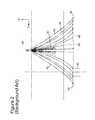
- FIG. 2shows a vessel 40 towing two cables 42 provided at respective ends with deflectors 44 .
- Plural lead-in cables 46are connected to streamers 50 .
- the plural lead-in cables 46also connect to the vessel 40 .
- the streamers 50are maintained at desired separations from each other by separation ropes 48 .
- Plural individual source elements 52are also connected to the vessel 40 and to the lead-in cables 46 via ropes 54 .
- a sensor 70(see FIG. 4 ) is removably attached to a pedestal 72 together with a memory device 74 . After recording the seismic waves, the sensor 70 together with the memory device 74 are instructed by a vessel 76 to detach from the pedestal 72 and to surface at the ocean surface 78 to be picked up by the vessel 76 .
- this configurationis not very reliable as the mechanism maintaining the sensor 70 connected to the pedestal 72 may fail to release the sensor 70 . Also, the sensor 70 and pedestal 72 may not achieve their intended positions on the seabed. Further, the fact that the pedestals 72 are left behind increase ocean pollution and the survey price, which are both undesirable.
- an autonomous underwater vehiclefor recording seismic signals during a marine seismic survey.
- the AUVincludes a body having a flush shape; an intake water element located on the body and configured to take in water when deployed underwater; at least one propulsion nozzle located at a tail or on a side of the body and configured to eject the water from the intake water element for actuating the AUV; at least one guidance nozzle located on the body and configured to eject water to change a travelling direction of the AUV; and a seismic payload located on the body of the AUV and configured to record seismic signals.
- an autonomous underwater vehiclefor recording seismic signals during a marine seismic survey.
- the AUVincludes a body having a smooth shape; a propulsion system located inside the body and having openings on a surface of the body for absorbing and ejecting water; a guidance system located inside the body and configured to change a position of a nose or a tail of the body while traveling underwater; and a seismic payload located on the body of the AUV and configured to record seismic signals.
- a method for recording seismic data with a seismic sensor located on an underwater autonomous vehicleincludes a step of providing the AUV with a seismic sensor; a step of launching the AUV into water; a step of steering the AUV based on an inertial navigation and/or acoustic system to a desired seabed location; a step of recording the seismic data; a step of returning the AUV on a vessel; and a step of transferring the seismic data from the AUV to the vessel while on board of the vessel.
- FIG. 1is a schematic diagram of a conventional seismic survey system
- FIG. 2illustrates a traditional arrangement of streamers and source arrays towed by a vessel
- FIG. 3is a schematic diagram of a station that may be positioned on the bottom of the ocean for seismic data recording
- FIG. 4is a schematic diagram of another station that may be positioned on the bottom of the ocean for seismic data recording;
- FIG. 5is a schematic diagram of an AUV according to an exemplary embodiment
- FIG. 6is a schematic diagram of another AUV according to an exemplary embodiment
- FIG. 7is a schematic diagram of still another AUV according to an exemplary embodiment
- FIG. 8is a cross-sectional view of an AUV according to an exemplary embodiment
- FIG. 9is a schematic diagram of a vessel for deploying and/or recovering an AUV according to an exemplary embodiment
- FIG. 10is a schematic diagram of a process for deploying and recovering AUVs according to an exemplary embodiment
- FIG. 11is a flowchart of a method for recycling AUVs during a seismic survey according to an exemplary embodiment
- FIG. 12is a schematic diagram of an AUV according to another exemplary embodiment
- FIG. 13is a schematic diagram of an AUV according to still another exemplary embodiment.
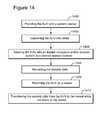
- FIG. 14is a flowchart of a method for deploying and recovering an AUV during a seismic survey.
- such a seismic systemincludes plural AUVs each having one or more seismic sensors.
- the seismic sensorsmay be one of a hydrophone, geophone, accelerometers, electromagnetic sensors, etc. If an electromagnetic sensor is used, then a source that emits electromagnetic waves may be used instead or in addition to an acoustic source.
- the AUVmay be a specially designed device or an off-the-shelf device so that it is inexpensive.
- the off-the-shelf devicemay be quickly retrofitted or modified to include the seismic sensors and necessary communication means to be discussed later.
- a deployment vesselstores the AUVs and launches them as necessary for the seismic survey.
- the AUVsfind their desired positions using, for example, an inertial navigation system.
- the AUVsmay be preprogrammed or partially programmed to find their desired positions. If the AUV are partially programmed, the final details for finding the desired position may be received, acoustically, from the vessel when the AUV is launched from the vessel.
- a deployment vessel or a recovery vesselIt is noted that these vessels may be identical from an equipment point of view.
- the vesselsmay be operated as a recovery vessel or as a deployment vessel.
- a recovery vesselmay be instructed, after having enough AUVs on board, to become a deployment vessel, and the other way around.
- the documentrefers to a vessel, that might be the recovery vessel, the launching vessel or both of them.
- a shooting vesselmay follow the deployment vessel for generating seismic waves.
- the shooting vesselmay tow one or more seismic source arrays.
- the shooting vessel or another vessel, e.g., the recovering vessel,may then instruct selected AUVs to resurface so that they can be collected.
- the deployment vesselalso tows source arrays and shoots them as it deploys the AUVs.
- only the deployment vesselis configured to retrieve the AUVs.
- a dedicated recovery vesselmay wake-up the AUVs and instruct them to return to the surface for recovery.
- the number of AUVsis in the thousands.
- the deployment vesselis configured to hold all of them at the beginning of the survey and then to launch them as the seismic survey is advancing. If the shooting vessel is configured to retrieve the AUVs, when the number of available AUVs at the deployment vessel is below a predetermined threshold, the shooting vessel and the deployment vessel are instructed to switch positions in the middle of the seismic survey. If a dedicated recovery vessel is used to recover the AUVs, then the deployment vessel is configured to switch positions with the recovery vessel when the deployment vessel becomes empty. In another exemplary embodiment, both vessels are full with AUVs. The first one starts deploying the AUVs and the second one just follow the first one. Once the first one has deployed most or all the AUVs, this vessel becomes the recovery vessel and the second one starts deploying AUVs, thus becoming the deployment vessel. Later, the two vessel may switch functions as necessary.
- the seismic surveyis performed as a combination of seismic sensors of the AUVs and seismic sensors of streamers towed by the deployment vessel, or the shooting vessel or by both of them.
- AUVswhen selected AUVs are instructed to surface, they may be programmed to go to a desired rendezvous point where they will be collected by the shooting vessel or by the deployment vessel or by the recovery vessel.
- the selected AUVsmay be chosen to belong to a given row or column if a row and column arrangement is used.
- the shooting or/and deployment or recovery vesselmay be configured to send acoustic signals to the returning AUVs for guiding them to the desired position.
- the AUVsmay be configured to rise to a given altitude, execute the return back path at that altitude and then surface for being recovered.
- the AUVsare configured to communicate among them so that they follow each other in their path back to the recovery vessel or they communicate among them to establish a queuing line for being retrieved by the shooting or recovery or deployment vessel.
- the recovery vesselmay store the AUVs on deck during the maintenance phase or somewhere inside the vessel, e.g., inside of a module, closed or open, that is fixed on the vessel or the vessel's deck.
- a conveyor-type mechanismmay be designed to recover the AUVs on one side of the vessel, when the vessel is used as a recovery vessel, and to launch the AUVs on another side of the vessel when the vessel is used as a deployment vessel.
- the AUVsare again deployed as the seismic survey continues.
- the AUVsare continuously deployed and retrieved.
- the AUVsare configured to not transmit the seismic data to the deployment or recovery or shooting vessel while performing the seismic survey. This may be advantageous as the electric power available on the AUV may be limited.
- each AUVhas enough electric power (stored in the battery) to only be once deployed, record seismic data and resurface to be retrieved. Thus, reducing the data transmission amount between the AUV and the vessel while the AUV is underwater conserves the power and allows the AUV to be retrieved on the vessel before running out of power.
- FIG. 5illustrates an AUV 100 having a body 102 to which one or more propellers 104 are attached.
- a motor 106is provided inside the body 102 for activating the propeller 104 .
- the motor 106may be controlled by a processor 108 .
- the processor 108may also be connected to a seismic sensor 110 .
- the seismic sensor 110may have such a shape that when the AUV lands on the seabed, the seismic sensor achieves a good coupling with the sediments on the seabed.
- the seismic sensormay include one or more of a hydrophone, geophone, accelerometer, etc.
- the seismic sensor 110includes three accelerometers and a hydrophone, i.e., a total of four sensors.
- the seismic sensormay include three geophones and a hydrophone.
- other combinations of sensorsare possible.
- a memory unit 112may be connected to the processor 108 and/or the seismic sensor 110 for storing seismic data recorded by the seismic sensor 110 .
- a battery 114may be used to power up all these components. The battery 114 may be allowed to change its position along a track 116 to change a center of gravity of the AUV.
- the AUVmay also include an inertial navigation system (INS) 118 configured to guide the AUV to a desired location.
- An inertial navigation systemincludes at least a module containing accelerometers, gyroscopes, or other motion-sensing devices.
- the INSis initially provided with the position and velocity of the AUV from another source, for example, a human operator, a GPS satellite receiver, another INS from the vessel, etc., and thereafter, the INS computes its own updated position and velocity by integrating (and optionally filtrating) information received from its motion sensors.
- the advantage of an INSis that it requires no external references in order to determine its position, orientation, or velocity once it has been initialized. Further, the usage of the INS is inexpensive.
- the AUVmay include a compass 120 and other sensors 122 , as for example, an altimeter for measuring its altitude, a pressure gauge, an interrogator module, etc.
- the AUV 100may optionally include an obstacle avoidance system 124 and a communication device 126 (e.g., wi-fi device) or other data transfer device that is capable to wirelessly transfer data.
- a communication device 126e.g., wi-fi device
- the AUVfurther includes an antenna 128 (which may be flush with the body of the AUV) and a corresponding acoustic system 130 for communicating with the deploying, recovery or shooting vessel.
- Stabilizing fins and/or wings 132 for guiding the AUV to the desired positionmay be used together with the propeller 104 for steering the AUV.
- the AUVmay include a buoyancy system 134 for controlling a depth of the AUV and also not moving once the AUV has landed.
- the acoustic system 130may be an Ultra-short baseline (USBL) system, also sometimes known as Super Short Base Line (SSBL).
- USBLUltra-short baseline
- SSBLSuper Short Base Line
- a complete USBL systemincludes a transceiver, which is mounted on a pole under a vessel, and a transponder/responder on the AUV.
- a processoris used to calculate a position from the ranges and bearings measured by the transceiver. For example, an acoustic pulse is transmitted by the transceiver and detected by the subsea transponder, which replies with its own acoustic pulse. This return pulse is detected by the transceiver on the vessel.
- the time from the transmission of the initial acoustic pulse until the reply is detectedis measured by the USBL system and is converted into a range.
- the USBLcalculates both a range and an angle from the transceiver to the subsea AUV. Angles are measured by the transceiver, which contains an array of transducers.
- the transceiver headnormally contains three or more transducers separated by a baseline of, e.g., 10 cm or less.
- FIG. 6shows another AUV 200 that can be used for seismic surveys.
- the AUV 200has a body 202 in the shape of a submarine.
- a water intake element 206may be provided at a nose 204 of the AUV or at another part of the AUV.
- one or more guidance nozzlesmay be provided on the nose 204 .
- FIG. 6shows three guidance nozzles, one nozzle 210 located on top of the nose 204 and two nozzles 208 and 212 located on the sides of the nose 204 . These guidance nozzles may be used to steer the AUV as needed.
- an impeller or water pump 213 watermay be provided inside the AUV for taking in water through the intake element or one of the guidance nozzles and then to expel the water through one or more of the guidance nozzles 208 , 210 and 212 for changing the direction of the AUV based on momentum conservation.
- Another possibilityis to have some valves instead of the water pump 213 that allow water entering the water intake element 206 to exit one or more of the guidance nozzles 208 , 210 and 212 as desired.
- Those skilled in the artcould imagine other mechanisms for steering the AUV.
- the AUV of FIG. 6may have two propulsion nozzles 220 and 222 at a tail region 224 .
- One or more than two nozzlesmay also be used.
- a water pump 216may be connected to the propulsion nozzles 220 and 222 for expelling the water through them.
- a valve 226may be installed to control how much of the intake water is provided to each of the propulsion nozzles 220 and 222 .
- another water intake elementinstead of using the water intake element 206 , another water intake element may be used, for example, a water intake element 228 located on the body 202 of the AUV.
- the pumps and valvesare connected to the processor 108 so that control of the AUV can be achieved by the INS.
- Some or all the elements shown inside the AUV 100 in FIG. 5may be present inside the AUV 200 .
- the antenna 128if present, is provided inside the body 202 of the AUV so that the AUV 200 is flush, i.e., it has no parts that stick out of the body 202 .
- an AUV 300also has a submarine type body with no elements coming out of the body 302 .
- the AUV 300has a propulsion mechanism that includes an intake water element 304 and two propulsion nozzles 306 and 308 .
- Appropriate piping 310 and 312connects the intake water element 304 to the propulsion nozzles 306 and 308 through an inside of the AUV.
- Impellers 314 and 316may be located in each pipe and connected to corresponding DC motors 314 a and 316 a , for forcing the water received from the intake water element 304 to exit with a controlled speed or volume at the propulsion nozzles 306 and 308 .
- the two DC motorsmay be brushless motors and they may be connected to the processor 108 for controlling a speed of the impellers.
- the impellersmay be controlled independently one from the other. Also, the impellers may be controlled to rotate in opposite directions (e.g., impeller 314 clockwise and impeller 316 counterclockwise) for increased stability of the AUV.
- guidance nozzles 320 a - cmay be provided on the bow part 322 of the AUV as shown in FIG. 7 .
- the guidance nozzles 320 a - cmay be distributed on the sides or corners of a triangle that lays in a plane perpendicular to a longitudinal axis X of the AUV 300 .
- One or three pump jets 324 a - cmay be also provided inside the body 302 for ejecting water through the guidance nozzles. In this way, a position of the bow of the AUV may be modified/changed while the AUV is moving through the water.
- a cross-section of the AUVmay be circular.
- the cross-section of the AUVis close to a triangle. More specifically, FIG. 8 shows a triangle 330 having round corners 332 .
- This shapemay be advantageous when deploying or recovering the AUV on the vessel.
- the launching (and/or recovery) device 340 of the vesselmay have a similar triangular shape and also rolling elements 342 a - c that are configured to rotate such that the AUV is lifted from the water into the vessel or lowered from the vessel into the sea.
- the rolling elements 342 a - cmay be located on the launching device 340 so that there is enough contact with the AUV that the AUV does not slip downward when the rolling elements push the AUV upward.
- Other shapesmay be imagined that could be handled by a launching device.
- a communication between the AUV and a vesselmay take place based on various technologies, i.e., acoustic waves, electromagnetic waves, etc.
- acoustic wavesi.e., acoustic waves, electromagnetic waves, etc.
- an acoustic underwater positioning and navigation (AUPN) systemmay be used.
- the AUPN systemmay be installed on any one of the participating vessels and may communicate with the acoustic system 130 of the AUV.
- the AUPN systemmay exhibit high accuracy and long range performance in both positioning and telemetry modes. These features are obtained due to the automatic beam forming transducers which focuses the sensitivity towards its targets or transponders. This beam can not only be pointed in any direction below the vessel, but also horizontally and even upwards to the surface as the transducer has the shape of a sphere.
- AUPNis a hydro-acoustic Super Short Base Line—SSBL or USBL, tow tracking system, able to operate in shallow and deepwater areas to proven ranges in excess of 3000 meters. It is a multi-purpose system used for a wide range of applications including towfish and towed platform tracking, high accuracy subsea positioning and telemetry and scientific research.
- the AUPNis used to determine the AUV position.
- the actual AUV's positionis measured with the AUPN and is then provided to the AUV, while moving to its desired position, to correct its INS trajectory.
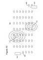
- a vessel for deploying and/or retrieving AUVsmay be configured according to an exemplary embodiment illustrated in FIG. 9 .
- a vessel 400includes a deploying mechanism 402 and a recovery mechanism 404 . Both the deploying and recovery mechanisms may include a corresponding chute 406 or 408 . Considering the recovery mechanism 404 , its chute 408 may have a funnel shape and may be deployed under water or at the surface water level.
- One or more beacons 410may be located on a rim of the chute 408 for directing an AUV 420 inside the chute. After entering the chute 408 , the recovered AUV 420 may engage a conveyor belt mechanism 422 or another hooking mechanism.
- the conveyor belt mechanism 422may be configured to take the AUV 420 to a maintenance area 424 .
- the maintenance area, inside the vessel 400may have one or more parallel tracks 424 a - c that split from a main track 426 . Each track 424 a - c takes corresponding AUVs 420 to appropriate maintenance locations.
- operators or robotsmay change or recharge the battery of the AUV, if depleted, and also may remove the memory unit of the AUV that stores the recorded seismic data.
- a new memory unitmay be provided to the AUV.
- the memoryis connected to a vessel memory unit 430 through a cable or a wireless interface and the data is transferred from the AUV's memory unit to the vessel's memory unit 430 .
- the AUVs 440having fresh or recharged batteries and memory units with enough available space may be provided to the deploying mechanism 402 for deployment.
- a vessel 400 having the mechanisms noted abovemay, at the same time, retrieve AUVs 420 and deploy AUVs 440 for implementing various seismic surveys.
- Those skilled in the artwould recognize that numerous modifications may be implemented for retrieving and deploying AUVs and those shown in the attached figures are for exemplary purposes.
- FIG. 10shows a seismic system 500 that includes a deployment vessel 502 and a recovery vessel 504 .
- the deployment vessel 502is tasked to deploy AUVs 506 while the recovery vessel 504 is tasked to recover AUVs 508 .
- dedicated shooting vessels 510 and 512follow their own path and generate acoustic waves.
- the deployment and recovery vesselsdo not tow source arrays.
- FIG. 10shows two shooting vessels, those skilled in the art would appreciate that one or more than two shooting vessels may be used.
- the deployment and recovery vesselsoperate continuously. When the deployment vessel is empty, it switches positions with the recovery vessel. The shooting of the sources may continue while the deployment and recovery vessels switch positions.
- step 1100the AUV is prepared for launching.
- This preparation phasei.e., conditioning the AUV if launched for the first time or reconditioning the AUV if recycled, may include one or more of charging the batteries, downloading seismic data, checking the system, etc.
- the mission data for that specific AUVis loaded in its processor. This step may take place while the AUV is on the deck of the vessel or the AUV is already loaded in its launching tube or ramp.
- the mission datamay include the present position of the AUV, the final desired position on the bottom of the ocean, and other parameters.
- the AUVis launched in step 1104 .
- the AUVis configured to use its INS (or acoustic communication or INS combined with acoustic communication) and the uploaded mission data to travel to its final destination.
- the AUVdoes not receive any information from the vessel while travelling. However, in another application, the AUV may receive additional information from the vessel, for example, its current position as measured by the AUPN of the vessel.
- beaconsmay be used to guide the AUV.
- some of the already deployed AUVmay function as beacons.
- step 1106after the AUV have settled to the seabed, the vessel interrogates the AUV about its position.
- the AUVresponds by sending a reference beam and the AUPN of the vessel determines the position of the AUV.
- the position of the AUVmay be determined with an accuracy of, for example, +/ ⁇ 2 m when the AUV is at a depth not larger than 300 m.
- step 1106may be performed between steps 1104 and 1108 , or between steps 1108 and 1110 or at the beginning of step 1110 or both.
- the AUVis ready to record seismic signals in step 1108 .
- This processmay last as long as necessary.
- the AUVis instructed in step 1110 , for example, using the AUPN of the recovery vessel to wake-up and start resurfacing.
- the AUVstarts its motor and moves towards the recovery vessel (the AUV can move in the direction of the recovery catcher, but the relative speed will be high, thus, the AUV may also move in the same direction as the boat, but slower, so that the relative speed is more reasonable, and the AUV can actively position itself to be catched by the catcher when the time is proper).
- the recovery vesselis the same with the deployment vessel.
- the AUVis helped to arrive at the recovery vessel by acoustic signals emitted by the recovery vessel.
- the AUVengages the recovery unit (e.g., chute) of the recovery vessel and the AUV is handled to arrive on the deck of the vessel for reconditioning as described in step 1100 .
- the AUVmay also be delivered under the deck of the recovery vessel for the reconditioning (maintenance) phase or in a back deck handling module fixed on the deck. Then, the whole process may be repeated so that the AUVs are constantly reused undersea for the seismic survey.
- FIG. 12shows an AUV 600 having a CPU 602 a that is connected to INS 604 (or compass or altitude sensor and acoustic transmitter for receiving acoustic guidance from the mother vessel), wireless interface 606 , pressure gauge 608 , transponder 610 .
- the CPU 602 amay be located in a high level control block 612 .
- the INSis advantageous when the AUV's trajectory has been changed, for example, because an encounter with an unexpected object, e.g., fish, debris, etc., because the INS is capable to take the AUV to the desired final position as it does for currents, wave motion, etc.
- the precision of the INSmay be high. For example, it is expected that for a target having a depth of 300 m, the INS is capable to steer the AUV within +/ ⁇ 5 m of the desired target location. However, the INS may be configured to receive data from the vessel to increase its accuracy. It is noted that the AUV 600 may reach a depth of 300 m.
- a CPU 602 bin addition to the CPU 602 a , is part of a low level control module 614 that is configured to control attitude actuators 616 and the propulsion system 618 .
- One or more batteries 620may be located in the AUV 600 .
- a seismic payload 622is located inside the AUV for recording the seismic signals.
- modulesmay be added to the AUV.
- a skirtmay be provided around or next to the sensor.
- a water pumpmay pump water from the skirt to achieve a suction effect so that a good coupling between the sensor and the seabed is achieved.
- no skirtis used.
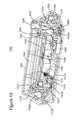
- FIG. 13shows an AUV 1300 having a body 1302 with a triangular-like shape.
- the bodymay be shaped differently.
- the body 1302includes a payload 1304 (e.g., seismic sensors as discussed above) and an acoustic transceiver 1306 that may partially extend outside the body 1302 .
- the acoustic transceiver 1306is configured to communicate with the vessel and receive acoustic guidance while traveling towards a desired target point.
- an INSmay be used for guidance.
- Many of the devices discussed in the above embodimentsmay be present in the body but are neither shown nor discussed with regard to this figure for simplicity.
- FIG. 13also shows a motor 1308 configured to rotate a propeller 1310 for providing thrust to the AUV 1300 .
- a motor 1308configured to rotate a propeller 1310 for providing thrust to the AUV 1300 .
- One or more motors and corresponding propellersmay be used.
- the propeller 1310receive water trough a channel 1312 formed into the body 1302 .
- the channel 1312has two openings 1312 a (intake water element) and 1312 b (propulsion nozzle) that communicate with the ambient water.
- the two openingsmay be located on the nose, tail or sides of the body 1302 .
- Guidance nozzles or turbinesmay be provided at a nose 1320 and/or at a tail 1322 of the body 1302 for rotation and/or translation control.
- the guidance nozzles and the turbinesare identified by the same reference numbers and are used interchangeable herein although FIG. 13 shows actual turbines.
- Three guidance nozzles 1320 a - cmay be located at the nose 1320 and three guidance nozzles 1322 a - c may be located at the tail 1322 of the body 1302 .
- the nozzlesare connected by piping to corresponding water pumps 1321 . If turbines are used instead of nozzles, no piping and no water pumps are necessary.
- the AUVhas the capability to adjust the position of its nose with the guidance nozzles (or turbines) 1320 a - c and the position of its tail with the guidance nozzles (or turbines) 1322 a - c .
- the tail nozzles or only the nose nozzlesmay be implemented.
- FIG. 13also shows one or more chambers 1340 and 1350 that communicate through piping 1342 and 1352 and vents 1330 with the ambient water so that the chambers may be flooded when desired.
- a control unit 1360may instruct the water pump to provide water into one or more of the chambers 1340 and 1350 (to partially or fully flood them) so that a buoyancy of the AUV becomes neutral or negative.
- the same control unit 1360can instruct the water pump (or use another mechanism) to discharge the water from the one or more chambers so that the buoyancy of the AUV becomes positive.
- the control unit 1360instructs one or more actuators 1370 to fluidly connect the vent 1330 to the flooding chamber for making the buoyancy of the AUV negative.
- control unit 1360instructs an accumulator 1372 to provide compressed gas (e.g., air, CO 2 , etc.) to the flooding chambers to expel the water and then the actuator 1370 seals closed the emptied flooding chambers.
- compressed gase.g., air, CO 2 , etc.
- the methodincludes a step 1400 of providing the AUV with a seismic sensor, a step 1402 of launching the AUV into water, a step 1404 of steering the AUV with an inertial navigation and/or acoustic system to a desired seabed location, a step 1406 of recording the seismic data, a step 1408 of returning the AUV on a vessel, and a step 1410 of transferring the seismic data from the AUV to the vessel while on board of the vessel.
Landscapes
- Engineering & Computer Science (AREA)
- Life Sciences & Earth Sciences (AREA)
- Mechanical Engineering (AREA)
- Physics & Mathematics (AREA)
- Aviation & Aerospace Engineering (AREA)
- Remote Sensing (AREA)
- Geology (AREA)
- Acoustics & Sound (AREA)
- Environmental & Geological Engineering (AREA)
- General Life Sciences & Earth Sciences (AREA)
- General Physics & Mathematics (AREA)
- Geophysics (AREA)
- Oceanography (AREA)
- Ocean & Marine Engineering (AREA)
- Geophysics And Detection Of Objects (AREA)
Abstract
Description
Claims (23)
Priority Applications (2)
| Application Number | Priority Date | Filing Date | Title |
|---|---|---|---|
| US13/616,481US9090319B2 (en) | 2011-09-30 | 2012-09-14 | Autonomous underwater vehicle for marine seismic surveys |
| US14/796,878US9821894B2 (en) | 2011-09-30 | 2015-07-10 | Autonomous underwater vehicle for marine seismic surveys |
Applications Claiming Priority (2)
| Application Number | Priority Date | Filing Date | Title |
|---|---|---|---|
| US201161541211P | 2011-09-30 | 2011-09-30 | |
| US13/616,481US9090319B2 (en) | 2011-09-30 | 2012-09-14 | Autonomous underwater vehicle for marine seismic surveys |
Related Child Applications (1)
| Application Number | Title | Priority Date | Filing Date |
|---|---|---|---|
| US14/796,878ContinuationUS9821894B2 (en) | 2011-09-30 | 2015-07-10 | Autonomous underwater vehicle for marine seismic surveys |
Publications (2)
| Publication Number | Publication Date |
|---|---|
| US20130083624A1 US20130083624A1 (en) | 2013-04-04 |
| US9090319B2true US9090319B2 (en) | 2015-07-28 |
Family
ID=47074680
Family Applications (2)
| Application Number | Title | Priority Date | Filing Date |
|---|---|---|---|
| US13/616,481Expired - Fee RelatedUS9090319B2 (en) | 2011-09-30 | 2012-09-14 | Autonomous underwater vehicle for marine seismic surveys |
| US14/796,878Active2032-10-09US9821894B2 (en) | 2011-09-30 | 2015-07-10 | Autonomous underwater vehicle for marine seismic surveys |
Family Applications After (1)
| Application Number | Title | Priority Date | Filing Date |
|---|---|---|---|
| US14/796,878Active2032-10-09US9821894B2 (en) | 2011-09-30 | 2015-07-10 | Autonomous underwater vehicle for marine seismic surveys |
Country Status (3)
| Country | Link |
|---|---|
| US (2) | US9090319B2 (en) |
| EP (2) | EP2760732B1 (en) |
| WO (1) | WO2013045669A1 (en) |
Cited By (36)
| Publication number | Priority date | Publication date | Assignee | Title |
|---|---|---|---|---|
| US20140251199A1 (en)* | 2013-02-06 | 2014-09-11 | Cgg Services Sa | Jet-pump-based autonomous underwater vehicle and method for coupling to ocean bottom during marine seismic survey |
| US20140321236A1 (en)* | 2013-04-25 | 2014-10-30 | Cgg Services Sa | Methods and underwater bases for using autonomous underwater vehicle for marine seismic surveys |
| US20150336646A1 (en)* | 2011-09-30 | 2015-11-26 | Seabed Geosolutions As | Autonomous underwater vehicle for marine seismic surveys |
| WO2016066721A1 (en) | 2014-10-29 | 2016-05-06 | Seabed Geosolutions B.V. | Touch down monitoring of an ocean bottom seismic node |
| US9381986B2 (en) | 2012-11-21 | 2016-07-05 | Seabed Geosolutions B.V. | Jet-pump-based autonomous underwater vehicle and method for coupling to ocean bottom during marine seismic survey |
| US20160202380A1 (en)* | 2015-01-14 | 2016-07-14 | Ion Geophysical Corporation | Ocean sensor system |
| US9457879B2 (en) | 2012-12-17 | 2016-10-04 | Seabed Geosolutions B.V. | Self-burying autonomous underwater vehicle and method for marine seismic surveys |
| US20170137098A1 (en)* | 2015-10-16 | 2017-05-18 | Seabed Geosolutions B.V. | Seismic autonomous underwater vehicle |
| US9720116B2 (en) | 2012-11-02 | 2017-08-01 | Fairfield Industries Incorporated | Land based unit for seismic data acquisition |
| US9829589B2 (en) | 2003-05-30 | 2017-11-28 | Fairfield Industries, Inc. | Ocean bottom seismometer package |
| US9845137B2 (en) | 2013-03-20 | 2017-12-19 | Seabed Geosolutions B.V. | Methods and underwater bases for using autonomous underwater vehicle for marine seismic surveys |
| US9873496B2 (en) | 2014-10-29 | 2018-01-23 | Seabed Geosolutions B.V. | Deployment and retrieval of seismic autonomous underwater vehicles |
| WO2018039121A1 (en) | 2016-08-22 | 2018-03-01 | Seabed Geosolutions B.V. | Wavegate for a seismic surface vessel |
| WO2018045019A1 (en) | 2016-09-01 | 2018-03-08 | Seabed Geosolutions B.V. | High angle deployment system for a seismic marine surface vessel |
| US9948405B1 (en)* | 2016-10-06 | 2018-04-17 | Fuji Xerox Co., Ltd. | Underwater mobile body |
| WO2018089382A1 (en) | 2016-11-09 | 2018-05-17 | Seabed Geosolutions B.V. | Modular containerized seismic source system |
| WO2018145011A1 (en) | 2017-02-06 | 2018-08-09 | Seabed Geosolutions B.V. | Methods and systems for deployment of seismic autonomous underwater vehicles |
| WO2018145012A1 (en) | 2017-02-06 | 2018-08-09 | Seabed Geosolutions B.V. | Ocean bottom seismic autonomous underwater vehicle |
| WO2018160459A1 (en) | 2017-03-02 | 2018-09-07 | Seabed Geosolutions B.V. | Elevator system on a subsea device for transfer of subsea payload |
| US10095230B1 (en) | 2016-09-13 | 2018-10-09 | Rockwell Collins, Inc. | Verified inference engine for autonomy |
| WO2018200305A1 (en) | 2017-04-27 | 2018-11-01 | Seabed Geosolutions B.V. | Control of remotely operated vehicle's dynamic positioning system by external navigation system |
| WO2018204084A1 (en) | 2017-05-02 | 2018-11-08 | Seabed Geosolutions B.V. | System and method for deploying ocean bottom seismic nodes using a plurality of underwater vehicles |
| US10384752B2 (en) | 2016-12-09 | 2019-08-20 | Seabed Geosolutions B.V. | Underwater vehicle docking system |
| US10502853B2 (en) | 2005-01-17 | 2019-12-10 | Magseis Ff Llc | Method and system for deployment of ocean bottom seismometers |
| US10514473B2 (en) | 2015-05-29 | 2019-12-24 | Seabed Geosolutions B.V. | Seabed coupling plate for an ocean bottom seismic node |
| US10545253B2 (en) | 2014-09-12 | 2020-01-28 | Cgg Services Sas | AUV based seismic acquisition system and method |
| US10641914B2 (en) | 2016-10-17 | 2020-05-05 | Seabed Geosolutions B.V. | Removable fastening mechanism for marine deployment of autonomous seismic nodes |
| US11124279B2 (en)* | 2017-12-28 | 2021-09-21 | Thales | Submarine vehicle and control method |
| US11237287B2 (en)* | 2018-05-23 | 2022-02-01 | Blue Ocean Seismic Services Limited | Autonomous data acquisition system and method |
| US11255998B2 (en) | 2018-05-17 | 2022-02-22 | Seabed Geosolutions B.V. | Cathedral body structure for an ocean bottom seismic node |
| US11442190B2 (en) | 2018-04-16 | 2022-09-13 | Pgs Geophysical As | Autonomous marine survey nodes |
| US11603175B2 (en) | 2019-07-30 | 2023-03-14 | Saudi Arabian Oil Company | Autonomous underwater vehicle to generate seismic waves |
| US11619757B2 (en) | 2018-04-16 | 2023-04-04 | Pgs Geophysical As | Modular system for deployment and retrieval of marine survey nodes |
| WO2023223101A1 (en)* | 2022-05-17 | 2023-11-23 | Cellula Robotics, Ltd. | Gnss-equipped auv for deploying positioning transponders |
| WO2024161139A1 (en) | 2023-02-01 | 2024-08-08 | Pxgeo Uk Limited | System and method for using autonomous underwater vehicles for ocean bottom seismic nodes |
| WO2025168935A1 (en) | 2024-02-06 | 2025-08-14 | Pxgeo Uk Limited | System and method for using autonomous underwater vehicles for ocean bottom seismic nodes |
Families Citing this family (10)
| Publication number | Priority date | Publication date | Assignee | Title |
|---|---|---|---|---|
| US9003986B2 (en)* | 2013-03-14 | 2015-04-14 | Saildrone, Inc. | Autonomous sailing vessel |
| KR101505643B1 (en)* | 2013-05-31 | 2015-03-25 | 삼성중공업 주식회사 | Apparatus for position control of streamer |
| FR3015052B1 (en) | 2013-12-17 | 2016-02-05 | Cgg Services Sa | METHOD AND DEVICE FOR MEASURING SOURCE SIGNATURE |
| US10006897B1 (en)* | 2014-03-28 | 2018-06-26 | Scott Howard Ensign | Devices for measuring parameters of water |
| WO2015161892A1 (en)* | 2014-04-25 | 2015-10-29 | Statoil Petroleum As | Optical underwater navigation |
| US10754352B1 (en)* | 2014-06-25 | 2020-08-25 | Santa Clara University | Multi-robot gradient based adaptive navigation system |
| US10363656B1 (en)* | 2014-06-25 | 2019-07-30 | Santa Clara University | Multi-robot gradient based adaptive navigation system |
| US10054104B1 (en)* | 2015-07-24 | 2018-08-21 | AJC Innovations, LLC | Autonomous underwater beacon locator |
| US10088584B2 (en)* | 2016-04-27 | 2018-10-02 | Proteus Technologies | Ship-towed hydrophone volumetric array system method |
| RU205521U1 (en)* | 2020-12-30 | 2021-07-19 | Федеральное государственное бюджетное образовательное учреждение высшего образования "Казанский национальный исследовательский технический университет им. А.Н. Туполева - КАИ" | Small-sized autonomous unmanned underwater vehicle with a variable vector of the propeller stop |
Citations (37)
| Publication number | Priority date | Publication date | Assignee | Title |
|---|---|---|---|---|
| GB2041301A (en) | 1979-02-02 | 1980-09-10 | Bell H | Submersibles |
| GB2163114A (en) | 1984-07-02 | 1986-02-19 | Offshore Syst Eng Osel | Improvements in or relating to underwater vehicles |
| US5253605A (en) | 1992-12-21 | 1993-10-19 | Applied Remote Technology, Inc. | Method and apparatus for deploying and recovering water borne vehicles |
| US5758592A (en)* | 1997-08-12 | 1998-06-02 | The United States Of America As Represented By The Secretary Of The Navy | Undersea vehicle propulsion and attitude control system |
| US5894450A (en) | 1997-04-15 | 1999-04-13 | Massachusetts Institute Of Technology | Mobile underwater arrays |
| WO2001073477A2 (en) | 2000-03-29 | 2001-10-04 | Westerngeco Seismic Holdings Ltd. | A submarine deployed ocean bottom seismic system |
| US6390012B1 (en) | 1999-09-20 | 2002-05-21 | Coflexip, S.A. | Apparatus and method for deploying, recovering, servicing, and operating an autonomous underwater vehicle |
| EP1217390A1 (en) | 2000-12-15 | 2002-06-26 | Institut Francais Du Petrole | Method and apparatus for marine seismic exploration, using detectors coupled with the water bottom |
| US6482054B2 (en)* | 2000-06-01 | 2002-11-19 | The Penn State Research Foundation | Tunnel thruster and water lubricated rotor duct assembly |
| EP1319964A2 (en) | 2001-12-10 | 2003-06-18 | Institut Francais Du Petrole | Seismic data acquisition system using acquisition stations positioned on the sea ground |
| US6779475B1 (en) | 2003-09-15 | 2004-08-24 | The United States Of America As Represented By The Secretary Of The Navy | Launch and recovery system for unmanned underwater vehicles |
| US6932185B2 (en) | 2002-08-22 | 2005-08-23 | Institut Francais Du Petrole | Acquisition method and device for seismic exploration of a geologic formation by permanent receivers set on the sea bottom |
| US7124698B1 (en)* | 2004-02-20 | 2006-10-24 | The United States Of America As Represented By The Secretary Of The Navy | Auxiliary facilities for the maneuvering of submerged water jet propelled sea craft |
| US7148416B1 (en) | 1995-08-31 | 2006-12-12 | The United States Of America As Represented By The Secretary Of The Navy | Undersea vehicle |
| US7252046B1 (en) | 2003-12-08 | 2007-08-07 | The United States Of America As Represented By The Secretary Of The Navy | Apparatus for deploying and recovering a towed acoustic line array from an unmanned undersea vehicle |
| US20100000459A1 (en) | 2008-07-01 | 2010-01-07 | Vladislav Francis Colangelo | LCAC lander, launcher and lifter |
| US20100157727A1 (en) | 2008-12-23 | 2010-06-24 | Fairfield Industries, Incorporated | Multiple receiver line deployment and recovery |
| US20100182870A1 (en) | 2007-08-10 | 2010-07-22 | Norris Michael W | Underseas seismic acquisition |
| US7796466B2 (en) | 2006-12-13 | 2010-09-14 | Westerngeco L.L.C. | Apparatus, systems and methods for seabed data acquisition |
| US20100302901A1 (en) | 2009-05-28 | 2010-12-02 | Welker Kenneth E | System and method of using autonomous underwater vehicle to facilitate seismic data acquisition |
| US7965583B2 (en)* | 2005-04-07 | 2011-06-21 | Cggveritas Services Sa | Method and apparatus for guiding seismic acquisition equipment |
| WO2011106237A2 (en) | 2010-02-23 | 2011-09-01 | Geco Technology B.V. | Seismic data acquisition using self-propelled underwater vehicles |
| US8025021B2 (en) | 2005-10-19 | 2011-09-27 | Go Science Limited | Submersible vehicle |
| CN102213594A (en) | 2011-03-16 | 2011-10-12 | 哈尔滨工程大学 | Method for fusing ocean current observation data of unmanned undersea vehicle (UUV) |
| US20110297121A1 (en) | 2008-12-16 | 2011-12-08 | Markus Kraus | Spark plug with a laser device in a prechamber |
| US8096254B1 (en) | 2010-03-29 | 2012-01-17 | The United States Of American As Represented By The Secretary Of The Navy | Unmanned vehicle launch and recovery system |
| WO2012013171A1 (en) | 2010-07-30 | 2012-02-02 | Atlas Elektronik Gmbh | Method and system for reconnoitering a region under water |
| WO2012013962A1 (en) | 2010-07-29 | 2012-02-02 | Bae Systems Plc | Buoyancy control in an unmannned underwater vehicle |
| US8109223B2 (en) | 2007-10-12 | 2012-02-07 | Subsea 7 Limited | Apparatus and method for operating autonomous underwater vehicles |
| US20120057430A1 (en)* | 2010-09-02 | 2012-03-08 | Ion Geophysical Corporation | Multi-component, acoustic-wave sensor and methods |
| US20120069702A1 (en) | 2010-09-17 | 2012-03-22 | Westerngeco L.L.C. | Marine seismic survey systems and methods using autonomously or remotely operated vehicles |
| WO2012085590A2 (en) | 2010-12-23 | 2012-06-28 | Go Science Limited | Deployment and retrieval of seabed device |
| WO2013041838A2 (en) | 2011-09-21 | 2013-03-28 | Go Science Limited | Deployment of seabed device |
| WO2013045669A1 (en) | 2011-09-30 | 2013-04-04 | Cggveritas Services Sa | Autonomous underwater vehicle for marine seismic surveys |
| WO2013076488A1 (en) | 2011-11-25 | 2013-05-30 | Go Science Limited | Annular vehicle with dipole antenna |
| WO2013128188A1 (en) | 2012-03-02 | 2013-09-06 | Go Science Limited | Communication with an underwater vehicle |
| WO2013128187A1 (en) | 2012-03-02 | 2013-09-06 | Go Science Limited | Determining position of underwater node |
Family Cites Families (6)
| Publication number | Priority date | Publication date | Assignee | Title |
|---|---|---|---|---|
| US3492965A (en)* | 1961-06-12 | 1970-02-03 | David J Wayfield | Propulsion system and related devices |
| US3256849A (en)* | 1964-05-20 | 1966-06-21 | Lehmann Guenther Wolfgang | Maneuver device for submergence vessels |
| US6951138B1 (en)* | 2000-11-01 | 2005-10-04 | Westerngeco L.L.C. | Method and apparatus for an ocean bottom seismic acquisition technique |
| US6829197B2 (en)* | 2001-09-17 | 2004-12-07 | Bae Systems Information And Electronic Systems Integration Inc | Acoustical imaging interferometer for detection of buried underwater objects |
| US7183742B2 (en)* | 2003-12-11 | 2007-02-27 | Honeywell International, Inc. | Unmanned underwater vehicle fuel cell powered charging system and method |
| US9174713B2 (en)* | 2012-11-02 | 2015-11-03 | Raytheon Company | Unmanned underwater vehicle |
- 2012
- 2012-09-14USUS13/616,481patent/US9090319B2/ennot_activeExpired - Fee Related
- 2012-09-28WOPCT/EP2012/069275patent/WO2013045669A1/enactiveApplication Filing
- 2012-09-28EPEP12778058.3Apatent/EP2760732B1/enactiveActive
- 2012-09-28EPEP21157449.6Apatent/EP3875360A1/ennot_activeWithdrawn
- 2015
- 2015-07-10USUS14/796,878patent/US9821894B2/enactiveActive
Patent Citations (43)
| Publication number | Priority date | Publication date | Assignee | Title |
|---|---|---|---|---|
| GB2041301A (en) | 1979-02-02 | 1980-09-10 | Bell H | Submersibles |
| GB2163114A (en) | 1984-07-02 | 1986-02-19 | Offshore Syst Eng Osel | Improvements in or relating to underwater vehicles |
| US5253605A (en) | 1992-12-21 | 1993-10-19 | Applied Remote Technology, Inc. | Method and apparatus for deploying and recovering water borne vehicles |
| US7148416B1 (en) | 1995-08-31 | 2006-12-12 | The United States Of America As Represented By The Secretary Of The Navy | Undersea vehicle |
| US5894450A (en) | 1997-04-15 | 1999-04-13 | Massachusetts Institute Of Technology | Mobile underwater arrays |
| US5758592A (en)* | 1997-08-12 | 1998-06-02 | The United States Of America As Represented By The Secretary Of The Navy | Undersea vehicle propulsion and attitude control system |
| US6474254B1 (en) | 1997-12-30 | 2002-11-05 | Westerngeco Llc | Submarine deployed ocean bottom seismic system |
| US6390012B1 (en) | 1999-09-20 | 2002-05-21 | Coflexip, S.A. | Apparatus and method for deploying, recovering, servicing, and operating an autonomous underwater vehicle |
| WO2001073477A2 (en) | 2000-03-29 | 2001-10-04 | Westerngeco Seismic Holdings Ltd. | A submarine deployed ocean bottom seismic system |
| US6482054B2 (en)* | 2000-06-01 | 2002-11-19 | The Penn State Research Foundation | Tunnel thruster and water lubricated rotor duct assembly |
| EP1217390A1 (en) | 2000-12-15 | 2002-06-26 | Institut Francais Du Petrole | Method and apparatus for marine seismic exploration, using detectors coupled with the water bottom |
| US6625083B2 (en) | 2000-12-15 | 2003-09-23 | Institut Francais Du Petrole | Method and device intended for seismic exploration of an underwater subsurface zone using seismic receivers coupled with the water bottom |
| EP1319964A2 (en) | 2001-12-10 | 2003-06-18 | Institut Francais Du Petrole | Seismic data acquisition system using acquisition stations positioned on the sea ground |
| US7016260B2 (en) | 2001-12-10 | 2006-03-21 | Institut Francais Du Petrole | Seismic data acquisition system using acquisition stations set on the sea bottom |
| US6932185B2 (en) | 2002-08-22 | 2005-08-23 | Institut Francais Du Petrole | Acquisition method and device for seismic exploration of a geologic formation by permanent receivers set on the sea bottom |
| US6779475B1 (en) | 2003-09-15 | 2004-08-24 | The United States Of America As Represented By The Secretary Of The Navy | Launch and recovery system for unmanned underwater vehicles |
| US7252046B1 (en) | 2003-12-08 | 2007-08-07 | The United States Of America As Represented By The Secretary Of The Navy | Apparatus for deploying and recovering a towed acoustic line array from an unmanned undersea vehicle |
| US7124698B1 (en)* | 2004-02-20 | 2006-10-24 | The United States Of America As Represented By The Secretary Of The Navy | Auxiliary facilities for the maneuvering of submerged water jet propelled sea craft |
| US8576658B2 (en) | 2005-04-07 | 2013-11-05 | Cggveritas Services Sa | Method for seismic acquisition on the seabed, guiding equipment, seismic acquisition equipment and seismic acquisition system for the implementation of this method |
| US7965583B2 (en)* | 2005-04-07 | 2011-06-21 | Cggveritas Services Sa | Method and apparatus for guiding seismic acquisition equipment |
| US8677921B2 (en) | 2005-10-19 | 2014-03-25 | Go Science Limited | Submersible vehicle with swept hull |
| US8025021B2 (en) | 2005-10-19 | 2011-09-27 | Go Science Limited | Submersible vehicle |
| US7796466B2 (en) | 2006-12-13 | 2010-09-14 | Westerngeco L.L.C. | Apparatus, systems and methods for seabed data acquisition |
| US20100182870A1 (en) | 2007-08-10 | 2010-07-22 | Norris Michael W | Underseas seismic acquisition |
| US8109223B2 (en) | 2007-10-12 | 2012-02-07 | Subsea 7 Limited | Apparatus and method for operating autonomous underwater vehicles |
| US20100000459A1 (en) | 2008-07-01 | 2010-01-07 | Vladislav Francis Colangelo | LCAC lander, launcher and lifter |
| US20110297121A1 (en) | 2008-12-16 | 2011-12-08 | Markus Kraus | Spark plug with a laser device in a prechamber |
| US20100157727A1 (en) | 2008-12-23 | 2010-06-24 | Fairfield Industries, Incorporated | Multiple receiver line deployment and recovery |
| US20100302901A1 (en) | 2009-05-28 | 2010-12-02 | Welker Kenneth E | System and method of using autonomous underwater vehicle to facilitate seismic data acquisition |
| US8717844B2 (en)* | 2010-02-23 | 2014-05-06 | Westerngeco L.L.C. | Seismic data acquisition using self-propelled underwater vehicles |
| WO2011106237A2 (en) | 2010-02-23 | 2011-09-01 | Geco Technology B.V. | Seismic data acquisition using self-propelled underwater vehicles |
| US8096254B1 (en) | 2010-03-29 | 2012-01-17 | The United States Of American As Represented By The Secretary Of The Navy | Unmanned vehicle launch and recovery system |
| WO2012013962A1 (en) | 2010-07-29 | 2012-02-02 | Bae Systems Plc | Buoyancy control in an unmannned underwater vehicle |
| WO2012013171A1 (en) | 2010-07-30 | 2012-02-02 | Atlas Elektronik Gmbh | Method and system for reconnoitering a region under water |
| US20120057430A1 (en)* | 2010-09-02 | 2012-03-08 | Ion Geophysical Corporation | Multi-component, acoustic-wave sensor and methods |
| US20120069702A1 (en) | 2010-09-17 | 2012-03-22 | Westerngeco L.L.C. | Marine seismic survey systems and methods using autonomously or remotely operated vehicles |
| WO2012085590A2 (en) | 2010-12-23 | 2012-06-28 | Go Science Limited | Deployment and retrieval of seabed device |
| CN102213594A (en) | 2011-03-16 | 2011-10-12 | 哈尔滨工程大学 | Method for fusing ocean current observation data of unmanned undersea vehicle (UUV) |
| WO2013041838A2 (en) | 2011-09-21 | 2013-03-28 | Go Science Limited | Deployment of seabed device |
| WO2013045669A1 (en) | 2011-09-30 | 2013-04-04 | Cggveritas Services Sa | Autonomous underwater vehicle for marine seismic surveys |
| WO2013076488A1 (en) | 2011-11-25 | 2013-05-30 | Go Science Limited | Annular vehicle with dipole antenna |
| WO2013128188A1 (en) | 2012-03-02 | 2013-09-06 | Go Science Limited | Communication with an underwater vehicle |
| WO2013128187A1 (en) | 2012-03-02 | 2013-09-06 | Go Science Limited | Determining position of underwater node |
Non-Patent Citations (8)
| Title |
|---|
| D. R. Yoerger, et al.; "Fine-scale seafloor survey in rugged deep-ocean terrain with an autonomous robot"; Robotics and Automation 2000, Proceedings, ICRA, International Conference on Apr. 24-28, 2000; Abstract; vol. 2; IEEE Eplore Digital Library; ISBN 0-7803-5886-4; Aug. 6, 2002; San Francisco, CA. |
| Hiroshi Yoshida, et al.; "New Attempts in the MR-X1 Sea-Trials: The Working AUV Tries to Survey of the Sea Floor and to Take Mud Samples"; Paper No. OMAE2010-20347; ASME 2010 29th International Conference on Ocean, Offshore and Arctic Engineering (MAE2010); Abstract; Jun. 6-11, 2010; Shanghai, China; [downloaded Feb. 28, 2012 at http://dx.doi.org/10.1115/OMAE2010-20347]. |
| International Search Report in corresponding International Application No. PCT/EP2012/069144 mailed Feb. 4, 2013. |
| International Search Report in corresponding International Application No. PCT/EP2012/069145 mailed Feb. 6, 2013. |
| Rhonda Duey; "'Flying' Nodes Shift Marine Seismic Paradigm'"; Dec. 1, 2011; pp. 1-2; [downloaded on Feb. 28, 2012 http://www.epmag.com/item/print/Flying-Nodes-Shift-Marine-Seismic-Paradigm-92689]. |
| Tadahiro Hyakudome; "Design of Autonomous Underwater Vehicle"; Japan Agency for Marine-Earth Science and Technology (JAMSTEC), Japan; International Journal of Advanced Robotic Systems; vol. 8, No. 1 (2011) ISSN 1729-8806; pp. 122-130; [downloaded from http://www.intechopen.com/journals/international-journal-of-advanced-robotic-systems/design-of-autonomous-underwater-vehicle]. |
| Written Opinion in corresponding International Application No. PCT/EP2012/069144 mailed Feb. 4, 2013. |
| Written Opinion in corresponding International Application No. PCT/EP2012/069145 mailed Feb. 6, 2013. |
Cited By (61)
| Publication number | Priority date | Publication date | Assignee | Title |
|---|---|---|---|---|
| US9829589B2 (en) | 2003-05-30 | 2017-11-28 | Fairfield Industries, Inc. | Ocean bottom seismometer package |
| US10539696B2 (en) | 2003-05-30 | 2020-01-21 | Magseis Ff Llc | Ocean bottom seismometer package |
| US11237285B2 (en) | 2003-05-30 | 2022-02-01 | Magseis Ff Llc | Ocean bottom seismometer package |
| US10422908B2 (en) | 2003-05-30 | 2019-09-24 | Magseis Ff Llc | Ocean bottom seismometer package |
| US10557958B2 (en) | 2003-05-30 | 2020-02-11 | Magseis Ff Llc | Ocean bottom seismometer package |
| US10502853B2 (en) | 2005-01-17 | 2019-12-10 | Magseis Ff Llc | Method and system for deployment of ocean bottom seismometers |
| US11131785B2 (en) | 2005-01-17 | 2021-09-28 | Magseis Ff Llc | Method and system for deployment of ocean bottom seismometers |
| US10591624B2 (en) | 2005-01-17 | 2020-03-17 | Magseis Ff Llc | Method and system for deployment of ocean bottom seismometers |
| US10598808B2 (en) | 2005-01-17 | 2020-03-24 | Magseis Ff Llc | Method and system for deployment of ocean bottom seismometers |
| US20150336646A1 (en)* | 2011-09-30 | 2015-11-26 | Seabed Geosolutions As | Autonomous underwater vehicle for marine seismic surveys |
| US9821894B2 (en)* | 2011-09-30 | 2017-11-21 | Seabed Geosolutions As | Autonomous underwater vehicle for marine seismic surveys |
| US9720116B2 (en) | 2012-11-02 | 2017-08-01 | Fairfield Industries Incorporated | Land based unit for seismic data acquisition |
| US9381986B2 (en) | 2012-11-21 | 2016-07-05 | Seabed Geosolutions B.V. | Jet-pump-based autonomous underwater vehicle and method for coupling to ocean bottom during marine seismic survey |
| US9821895B2 (en) | 2012-11-21 | 2017-11-21 | Seabed Geosolutions B.V. | Autonomous underwater vehicle and method for coupling to ocean bottom during marine seismic survey |
| US9457879B2 (en) | 2012-12-17 | 2016-10-04 | Seabed Geosolutions B.V. | Self-burying autonomous underwater vehicle and method for marine seismic surveys |
| US20140251199A1 (en)* | 2013-02-06 | 2014-09-11 | Cgg Services Sa | Jet-pump-based autonomous underwater vehicle and method for coupling to ocean bottom during marine seismic survey |
| US9845137B2 (en) | 2013-03-20 | 2017-12-19 | Seabed Geosolutions B.V. | Methods and underwater bases for using autonomous underwater vehicle for marine seismic surveys |
| US10787235B2 (en) | 2013-03-20 | 2020-09-29 | Seabed Geosolutions B.V. | Methods and underwater bases for using autonomous underwater vehicles for marine seismic surveys |
| US9321514B2 (en)* | 2013-04-25 | 2016-04-26 | Cgg Services Sa | Methods and underwater bases for using autonomous underwater vehicle for marine seismic surveys |
| US10017232B2 (en) | 2013-04-25 | 2018-07-10 | Cgg Services Sas | Methods and underwater bases for using autonomous underwater vehicle for marine seismic surveys |
| US20140321236A1 (en)* | 2013-04-25 | 2014-10-30 | Cgg Services Sa | Methods and underwater bases for using autonomous underwater vehicle for marine seismic surveys |
| US10545253B2 (en) | 2014-09-12 | 2020-01-28 | Cgg Services Sas | AUV based seismic acquisition system and method |
| US11059552B2 (en) | 2014-10-29 | 2021-07-13 | Seabed Geosolutions B.V. | Deployment and retrieval of seismic autonomous underwater vehicles |
| US9873496B2 (en) | 2014-10-29 | 2018-01-23 | Seabed Geosolutions B.V. | Deployment and retrieval of seismic autonomous underwater vehicles |
| US9891333B2 (en) | 2014-10-29 | 2018-02-13 | Seabed Geosolutions B.V. | Touch down monitoring of an ocean bottom seismic node |
| US10099760B2 (en) | 2014-10-29 | 2018-10-16 | Seabed Geosolutions B.V. | Deployment and retrieval of seismic autonomous underwater vehicles |
| WO2016066721A1 (en) | 2014-10-29 | 2016-05-06 | Seabed Geosolutions B.V. | Touch down monitoring of an ocean bottom seismic node |
| US10488540B2 (en)* | 2015-01-14 | 2019-11-26 | Ion Geophysical Corporation | Ocean sensor system |
| US20160202380A1 (en)* | 2015-01-14 | 2016-07-14 | Ion Geophysical Corporation | Ocean sensor system |
| US10514473B2 (en) | 2015-05-29 | 2019-12-24 | Seabed Geosolutions B.V. | Seabed coupling plate for an ocean bottom seismic node |
| US10322783B2 (en)* | 2015-10-16 | 2019-06-18 | Seabed Geosolutions B.V. | Seismic autonomous underwater vehicle |
| US20170137098A1 (en)* | 2015-10-16 | 2017-05-18 | Seabed Geosolutions B.V. | Seismic autonomous underwater vehicle |
| WO2018039121A1 (en) | 2016-08-22 | 2018-03-01 | Seabed Geosolutions B.V. | Wavegate for a seismic surface vessel |
| WO2018045019A1 (en) | 2016-09-01 | 2018-03-08 | Seabed Geosolutions B.V. | High angle deployment system for a seismic marine surface vessel |
| US10955843B1 (en) | 2016-09-13 | 2021-03-23 | Rockwell Collins, Inc. | Verified inference engine for autonomy |
| US10095230B1 (en) | 2016-09-13 | 2018-10-09 | Rockwell Collins, Inc. | Verified inference engine for autonomy |
| US9948405B1 (en)* | 2016-10-06 | 2018-04-17 | Fuji Xerox Co., Ltd. | Underwater mobile body |
| US10641914B2 (en) | 2016-10-17 | 2020-05-05 | Seabed Geosolutions B.V. | Removable fastening mechanism for marine deployment of autonomous seismic nodes |
| WO2018089382A1 (en) | 2016-11-09 | 2018-05-17 | Seabed Geosolutions B.V. | Modular containerized seismic source system |
| US10384752B2 (en) | 2016-12-09 | 2019-08-20 | Seabed Geosolutions B.V. | Underwater vehicle docking system |
| WO2018145011A1 (en) | 2017-02-06 | 2018-08-09 | Seabed Geosolutions B.V. | Methods and systems for deployment of seismic autonomous underwater vehicles |
| US11267546B2 (en) | 2017-02-06 | 2022-03-08 | Seabed Geosolutions B.V. | Ocean bottom seismic autonomous underwater vehicle |
| WO2018145012A1 (en) | 2017-02-06 | 2018-08-09 | Seabed Geosolutions B.V. | Ocean bottom seismic autonomous underwater vehicle |
| US10543892B2 (en) | 2017-02-06 | 2020-01-28 | Seabed Geosolutions B.V. | Ocean bottom seismic autonomous underwater vehicle |
| WO2018160459A1 (en) | 2017-03-02 | 2018-09-07 | Seabed Geosolutions B.V. | Elevator system on a subsea device for transfer of subsea payload |
| US10386521B2 (en) | 2017-03-02 | 2019-08-20 | Seabed Geosolutions B.V. | Elevator system on a subsea device for transfer of subsea payload |
| WO2018200305A1 (en) | 2017-04-27 | 2018-11-01 | Seabed Geosolutions B.V. | Control of remotely operated vehicle's dynamic positioning system by external navigation system |
| US11634198B2 (en) | 2017-04-27 | 2023-04-25 | Seabed Geosolutions B.V. | Control of remotely operated vehicle's dynamic positioning system by external navigation system |
| WO2018204084A1 (en) | 2017-05-02 | 2018-11-08 | Seabed Geosolutions B.V. | System and method for deploying ocean bottom seismic nodes using a plurality of underwater vehicles |
| US11442191B2 (en) | 2017-05-02 | 2022-09-13 | Seabed Geosolutions B.V. | System and method for deploying ocean bottom seismic nodes using a plurality of underwater vehicles |
| US11124279B2 (en)* | 2017-12-28 | 2021-09-21 | Thales | Submarine vehicle and control method |
| US11442190B2 (en) | 2018-04-16 | 2022-09-13 | Pgs Geophysical As | Autonomous marine survey nodes |
| US11619757B2 (en) | 2018-04-16 | 2023-04-04 | Pgs Geophysical As | Modular system for deployment and retrieval of marine survey nodes |
| US11255998B2 (en) | 2018-05-17 | 2022-02-22 | Seabed Geosolutions B.V. | Cathedral body structure for an ocean bottom seismic node |
| US11269103B2 (en)* | 2018-05-23 | 2022-03-08 | Blue Ocean Seismic Services Limited | Autonomous data acquisition system and method |
| US11237287B2 (en)* | 2018-05-23 | 2022-02-01 | Blue Ocean Seismic Services Limited | Autonomous data acquisition system and method |
| US11906681B2 (en) | 2018-05-23 | 2024-02-20 | Blue Ocean Seismic Services Limited | Autonomous data acquisition system and method |
| US11603175B2 (en) | 2019-07-30 | 2023-03-14 | Saudi Arabian Oil Company | Autonomous underwater vehicle to generate seismic waves |
| WO2023223101A1 (en)* | 2022-05-17 | 2023-11-23 | Cellula Robotics, Ltd. | Gnss-equipped auv for deploying positioning transponders |
| WO2024161139A1 (en) | 2023-02-01 | 2024-08-08 | Pxgeo Uk Limited | System and method for using autonomous underwater vehicles for ocean bottom seismic nodes |
| WO2025168935A1 (en) | 2024-02-06 | 2025-08-14 | Pxgeo Uk Limited | System and method for using autonomous underwater vehicles for ocean bottom seismic nodes |
Also Published As
| Publication number | Publication date |
|---|---|
| EP2760732B1 (en) | 2021-02-17 |
| EP3875360A1 (en) | 2021-09-08 |
| US20130083624A1 (en) | 2013-04-04 |
| EP2760732A1 (en) | 2014-08-06 |
| US20150336646A1 (en) | 2015-11-26 |
| US9821894B2 (en) | 2017-11-21 |
| WO2013045669A1 (en) | 2013-04-04 |
Similar Documents
| Publication | Publication Date | Title |
|---|---|---|
| US9821894B2 (en) | Autonomous underwater vehicle for marine seismic surveys | |
| US9457879B2 (en) | Self-burying autonomous underwater vehicle and method for marine seismic surveys | |
| US20150336645A1 (en) | Autonomous underwater vehicle marine seismic surveys | |
| US9821895B2 (en) | Autonomous underwater vehicle and method for coupling to ocean bottom during marine seismic survey | |
| US9969470B2 (en) | Deployment and recovery of autonomous underwater vehicles for seismic survey | |
| US9417351B2 (en) | Marine seismic surveys using clusters of autonomous underwater vehicles | |
| EP2920613B1 (en) | Marine seismic survey and method using autonomous underwater vehicles and underwater bases | |
| US9625597B2 (en) | Acoustic modem-based guiding method for autonomous underwater vehicle for marine seismic surveys | |
| EP2760729B1 (en) | Deployment and recovery vessel for autonomous underwater vehicle for seismic survey | |
| US9849953B2 (en) | Autonomous underwater vehicle for marine seismic surveys | |
| US20130083622A1 (en) | Underwater node for seismic surveys | |
| US20140251199A1 (en) | Jet-pump-based autonomous underwater vehicle and method for coupling to ocean bottom during marine seismic survey |
Legal Events
| Date | Code | Title | Description |
|---|---|---|---|
| AS | Assignment | Owner name:CGGVERITAS SERVICES SA, FRANCE Free format text:ASSIGNMENT OF ASSIGNORS INTEREST;ASSIGNORS:BRIZARD, THIERRY;HERVE, ALICE;GRIMSDALE, JONATHAN;AND OTHERS;SIGNING DATES FROM 20120907 TO 20120912;REEL/FRAME:028967/0971 | |
| AS | Assignment | Owner name:CGGVERITAS SERVICES (NORWAY) AS, NORWAY Free format text:ASSIGNMENT OF ASSIGNORS INTEREST;ASSIGNOR:CGGVERITAS SERVICES SA;REEL/FRAME:029622/0346 Effective date:20121220 | |
| AS | Assignment | Owner name:SEABED GEOSOLUTIONS R&D AS, NORWAY Free format text:CHANGE OF NAME;ASSIGNOR:CGGVERITAS SEABED AS;REEL/FRAME:032133/0406 Effective date:20130427 Owner name:CGGVERITAS SEABED AS, NORWAY Free format text:CHANGE OF NAME;ASSIGNOR:CGGVERITAS SERVICES (NORWAY) AS;REEL/FRAME:032133/0369 Effective date:20130212 | |
| AS | Assignment | Owner name:SEABED GEOSOLUTIONS AS, NORWAY Free format text:MERGER AND CHANGE OF NAME;ASSIGNORS:SEABED GEOSOLUTIONS R&D AS;SEABED GEOSOLUTIONS AS;REEL/FRAME:035392/0985 Effective date:20140506 | |
| STCF | Information on status: patent grant | Free format text:PATENTED CASE | |
| MAFP | Maintenance fee payment | Free format text:PAYMENT OF MAINTENANCE FEE, 4TH YEAR, LARGE ENTITY (ORIGINAL EVENT CODE: M1551); ENTITY STATUS OF PATENT OWNER: LARGE ENTITY Year of fee payment:4 | |
| FEPP | Fee payment procedure | Free format text:MAINTENANCE FEE REMINDER MAILED (ORIGINAL EVENT CODE: REM.); ENTITY STATUS OF PATENT OWNER: LARGE ENTITY | |
| LAPS | Lapse for failure to pay maintenance fees | Free format text:PATENT EXPIRED FOR FAILURE TO PAY MAINTENANCE FEES (ORIGINAL EVENT CODE: EXP.); ENTITY STATUS OF PATENT OWNER: LARGE ENTITY | |
| STCH | Information on status: patent discontinuation | Free format text:PATENT EXPIRED DUE TO NONPAYMENT OF MAINTENANCE FEES UNDER 37 CFR 1.362 | |
| FP | Lapsed due to failure to pay maintenance fee | Effective date:20230728 |