US9089718B2 - Defibrillation system - Google Patents
Defibrillation systemDownload PDFInfo
- Publication number
- US9089718B2 US9089718B2US14/308,119US201414308119AUS9089718B2US 9089718 B2US9089718 B2US 9089718B2US 201414308119 AUS201414308119 AUS 201414308119AUS 9089718 B2US9089718 B2US 9089718B2
- Authority
- US
- United States
- Prior art keywords
- patient
- defibrillator
- defibrillation
- electrode
- processor
- Prior art date
- Legal status (The legal status is an assumption and is not a legal conclusion. Google has not performed a legal analysis and makes no representation as to the accuracy of the status listed.)
- Expired - Fee Related
Links
- 230000004044responseEffects0.000claimsabstractdescription59
- 230000015654memoryEffects0.000claimsabstractdescription57
- 238000000034methodMethods0.000claimsabstractdescription30
- 239000003990capacitorSubstances0.000claimsdescription66
- 210000000115thoracic cavityAnatomy0.000claimsdescription48
- 230000000694effectsEffects0.000claimsdescription29
- 230000005540biological transmissionEffects0.000claimsdescription27
- 230000033001locomotionEffects0.000claimsdescription19
- 230000007774longtermEffects0.000claimsdescription14
- 230000002159abnormal effectEffects0.000claimsdescription9
- 239000004744fabricSubstances0.000claimsdescription9
- 229920000742CottonPolymers0.000claimsdescription2
- 229920002334SpandexPolymers0.000claimsdescription2
- 239000004759spandexSubstances0.000claimsdescription2
- 238000012544monitoring processMethods0.000abstractdescription21
- 206010047302ventricular tachycardiaDiseases0.000abstractdescription13
- 230000003213activating effectEffects0.000abstractdescription5
- 238000002565electrocardiographyMethods0.000description120
- 238000012360testing methodMethods0.000description77
- 238000004458analytical methodMethods0.000description53
- 238000012545processingMethods0.000description42
- 206010003119arrhythmiaDiseases0.000description41
- 230000033764rhythmic processEffects0.000description40
- 239000000853adhesiveSubstances0.000description33
- 230000001070adhesive effectEffects0.000description33
- 230000006793arrhythmiaEffects0.000description29
- 229910052751metalInorganic materials0.000description28
- 239000002184metalSubstances0.000description28
- 230000000638stimulationEffects0.000description26
- 238000004422calculation algorithmMethods0.000description21
- 239000000463materialSubstances0.000description20
- 239000011888foilSubstances0.000description19
- 239000010410layerSubstances0.000description18
- 238000004891communicationMethods0.000description17
- 230000006870functionEffects0.000description17
- 238000005259measurementMethods0.000description17
- 230000000007visual effectEffects0.000description17
- 239000000017hydrogelSubstances0.000description16
- 230000000069prophylactic effectEffects0.000description15
- 230000001225therapeutic effectEffects0.000description15
- 239000003795chemical substances by applicationSubstances0.000description14
- 208000003663ventricular fibrillationDiseases0.000description14
- 230000000747cardiac effectEffects0.000description13
- 238000003491arrayMethods0.000description12
- 239000004020conductorSubstances0.000description12
- 239000011159matrix materialSubstances0.000description12
- 239000003351stiffenerSubstances0.000description12
- 208000003443UnconsciousnessDiseases0.000description11
- 238000010586diagramMethods0.000description11
- 238000002560therapeutic procedureMethods0.000description11
- 238000002847impedance measurementMethods0.000description9
- 230000008569processEffects0.000description9
- 206010040880Skin irritationDiseases0.000description8
- 230000007547defectEffects0.000description8
- 238000001514detection methodMethods0.000description8
- 235000021251pulsesNutrition0.000description8
- 230000036556skin irritationEffects0.000description8
- 231100000475skin irritationToxicity0.000description8
- 230000008901benefitEffects0.000description7
- 238000007906compressionMethods0.000description7
- 230000006835compressionEffects0.000description7
- 150000002500ionsChemical class0.000description7
- 230000006378damageEffects0.000description6
- 230000001788irregularEffects0.000description6
- 230000007794irritationEffects0.000description6
- 230000002829reductive effectEffects0.000description6
- 230000007480spreadingEffects0.000description6
- 238000003892spreadingMethods0.000description6
- 210000001519tissueAnatomy0.000description6
- XLYOFNOQVPJJNP-UHFFFAOYSA-NwaterSubstancesOXLYOFNOQVPJJNP-UHFFFAOYSA-N0.000description6
- OKTJSMMVPCPJKN-UHFFFAOYSA-NCarbonChemical compound[C]OKTJSMMVPCPJKN-UHFFFAOYSA-N0.000description5
- PEDCQBHIVMGVHV-UHFFFAOYSA-NGlycerineChemical compoundOCC(O)COPEDCQBHIVMGVHV-UHFFFAOYSA-N0.000description5
- 230000036471bradycardiaEffects0.000description5
- 229910052799carbonInorganic materials0.000description5
- 239000006071creamSubstances0.000description5
- 230000007423decreaseEffects0.000description5
- 238000001914filtrationMethods0.000description5
- 230000009467reductionEffects0.000description5
- 230000029058respiratory gaseous exchangeEffects0.000description5
- 230000001360synchronised effectEffects0.000description5
- 238000010200validation analysisMethods0.000description5
- FAPWRFPIFSIZLT-UHFFFAOYSA-MSodium chlorideChemical compound[Na+].[Cl-]FAPWRFPIFSIZLT-UHFFFAOYSA-M0.000description4
- 208000006218bradycardiaDiseases0.000description4
- 230000008602contractionEffects0.000description4
- 238000007667floatingMethods0.000description4
- 230000000737periodic effectEffects0.000description4
- 229920001296polysiloxanePolymers0.000description4
- 230000001755vocal effectEffects0.000description4
- WCUXLLCKKVVCTQ-UHFFFAOYSA-MPotassium chlorideChemical compound[Cl-].[K+]WCUXLLCKKVVCTQ-UHFFFAOYSA-M0.000description3
- DNIAPMSPPWPWGF-UHFFFAOYSA-NPropylene glycolChemical compoundCC(O)CODNIAPMSPPWPWGF-UHFFFAOYSA-N0.000description3
- 238000009825accumulationMethods0.000description3
- 230000017531blood circulationEffects0.000description3
- 238000006243chemical reactionMethods0.000description3
- KRKNYBCHXYNGOX-UHFFFAOYSA-Ncitric acidChemical compoundOC(=O)CC(O)(C(O)=O)CC(O)=OKRKNYBCHXYNGOX-UHFFFAOYSA-N0.000description3
- 230000003750conditioning effectEffects0.000description3
- 230000002939deleterious effectEffects0.000description3
- 230000035876healingEffects0.000description3
- 239000003112inhibitorSubstances0.000description3
- 230000003993interactionEffects0.000description3
- 230000007257malfunctionEffects0.000description3
- 238000003825pressingMethods0.000description3
- 239000003223protective agentSubstances0.000description3
- 230000008672reprogrammingEffects0.000description3
- 238000012552reviewMethods0.000description3
- 150000003839saltsChemical class0.000description3
- 238000005070samplingMethods0.000description3
- 238000007789sealingMethods0.000description3
- 230000035939shockEffects0.000description3
- 229910052709silverInorganic materials0.000description3
- 239000004332silverSubstances0.000description3
- 230000037380skin damageEffects0.000description3
- 239000003381stabilizerSubstances0.000description3
- 238000012546transferMethods0.000description3
- 238000011282treatmentMethods0.000description3
- 238000012935AveragingMethods0.000description2
- WHXSMMKQMYFTQS-UHFFFAOYSA-NLithiumChemical compound[Li]WHXSMMKQMYFTQS-UHFFFAOYSA-N0.000description2
- 239000004909MoisturizerSubstances0.000description2
- PXHVJJICTQNCMI-UHFFFAOYSA-NNickelChemical compound[Ni]PXHVJJICTQNCMI-UHFFFAOYSA-N0.000description2
- 102100026827Protein associated with UVRAG as autophagy enhancerHuman genes0.000description2
- 101710102978Protein associated with UVRAG as autophagy enhancerProteins0.000description2
- 229910021607Silver chlorideInorganic materials0.000description2
- ATJFFYVFTNAWJD-UHFFFAOYSA-NTinChemical compound[Sn]ATJFFYVFTNAWJD-UHFFFAOYSA-N0.000description2
- XLOMVQKBTHCTTD-UHFFFAOYSA-NZinc monoxideChemical compound[Zn]=OXLOMVQKBTHCTTD-UHFFFAOYSA-N0.000description2
- 230000009471actionEffects0.000description2
- POJWUDADGALRAB-UHFFFAOYSA-NallantoinChemical compoundNC(=O)NC1NC(=O)NC1=OPOJWUDADGALRAB-UHFFFAOYSA-N0.000description2
- 230000000844anti-bacterial effectEffects0.000description2
- 239000003899bactericide agentSubstances0.000description2
- ISAOCJYIOMOJEB-UHFFFAOYSA-NbenzoinChemical compoundC=1C=CC=CC=1C(O)C(=O)C1=CC=CC=C1ISAOCJYIOMOJEB-UHFFFAOYSA-N0.000description2
- 230000000981bystanderEffects0.000description2
- 238000002680cardiopulmonary resuscitationMethods0.000description2
- 210000000038chestAnatomy0.000description2
- 238000010276constructionMethods0.000description2
- 230000007797corrosionEffects0.000description2
- 238000005260corrosionMethods0.000description2
- 239000013078crystalSubstances0.000description2
- 238000013461designMethods0.000description2
- 239000003974emollient agentSubstances0.000description2
- 239000003292glueSubstances0.000description2
- 150000004676glycansChemical class0.000description2
- 235000011187glycerolNutrition0.000description2
- 239000013003healing agentSubstances0.000description2
- 230000000887hydrating effectEffects0.000description2
- JYGXADMDTFJGBT-VWUMJDOOSA-NhydrocortisoneChemical compoundO=C1CC[C@]2(C)[C@H]3[C@@H](O)C[C@](C)([C@@](CC4)(O)C(=O)CO)[C@@H]4[C@@H]3CCC2=C1JYGXADMDTFJGBT-VWUMJDOOSA-N0.000description2
- 238000009413insulationMethods0.000description2
- 229910052744lithiumInorganic materials0.000description2
- 230000013011matingEffects0.000description2
- OSWPMRLSEDHDFF-UHFFFAOYSA-Nmethyl salicylateChemical compoundCOC(=O)C1=CC=CC=C1OOSWPMRLSEDHDFF-UHFFFAOYSA-N0.000description2
- 239000000203mixtureSubstances0.000description2
- 238000012986modificationMethods0.000description2
- 230000004048modificationEffects0.000description2
- 230000001333moisturizerEffects0.000description2
- 230000004118muscle contractionEffects0.000description2
- 230000007935neutral effectEffects0.000description2
- 229920000642polymerPolymers0.000description2
- 239000005017polysaccharideSubstances0.000description2
- 229920001282polysaccharidePolymers0.000description2
- -1polytetrafluoroethylenePolymers0.000description2
- 230000002035prolonged effectEffects0.000description2
- 238000005086pumpingMethods0.000description2
- 230000000717retained effectEffects0.000description2
- 238000012502risk assessmentMethods0.000description2
- 238000011076safety testMethods0.000description2
- YGSDEFSMJLZEOE-UHFFFAOYSA-Nsalicylic acidChemical compoundOC(=O)C1=CC=CC=C1OYGSDEFSMJLZEOE-UHFFFAOYSA-N0.000description2
- 238000000926separation methodMethods0.000description2
- HKZLPVFGJNLROG-UHFFFAOYSA-Msilver monochlorideChemical compound[Cl-].[Ag+]HKZLPVFGJNLROG-UHFFFAOYSA-M0.000description2
- 239000011780sodium chlorideSubstances0.000description2
- 239000007787solidSubstances0.000description2
- 238000010183spectrum analysisMethods0.000description2
- 230000003068static effectEffects0.000description2
- 238000003860storageMethods0.000description2
- 150000005846sugar alcoholsPolymers0.000description2
- 238000001356surgical procedureMethods0.000description2
- 238000012731temporal analysisMethods0.000description2
- 229910052718tinInorganic materials0.000description2
- 238000012549trainingMethods0.000description2
- 230000007704transitionEffects0.000description2
- 230000002861ventricularEffects0.000description2
- FPIPGXGPPPQFEQ-UHFFFAOYSA-N13-cis retinolNatural productsOCC=C(C)C=CC=C(C)C=CC1=C(C)CCCC1(C)CFPIPGXGPPPQFEQ-UHFFFAOYSA-N0.000description1
- KKAJSJJFBSOMGS-UHFFFAOYSA-N3,6-diamino-10-methylacridinium chlorideChemical compound[Cl-].C1=C(N)C=C2[N+](C)=C(C=C(N)C=C3)C3=CC2=C1KKAJSJJFBSOMGS-UHFFFAOYSA-N0.000description1
- ZCYVEMRRCGMTRW-UHFFFAOYSA-N7553-56-2Chemical compound[I]ZCYVEMRRCGMTRW-UHFFFAOYSA-N0.000description1
- 235000007173Abies balsameaNutrition0.000description1
- 244000215068Acacia senegalSpecies0.000description1
- 235000006491Acacia senegalNutrition0.000description1
- 102100027241Adenylyl cyclase-associated protein 1Human genes0.000description1
- POJWUDADGALRAB-PVQJCKRUSA-NAllantoinNatural productsNC(=O)N[C@@H]1NC(=O)NC1=OPOJWUDADGALRAB-PVQJCKRUSA-N0.000description1
- 244000144927Aloe barbadensisSpecies0.000description1
- 235000002961Aloe barbadensisNutrition0.000description1
- 206010003658Atrial FibrillationDiseases0.000description1
- 206010003662Atrial flutterDiseases0.000description1
- 206010003671Atrioventricular BlockDiseases0.000description1
- 108010001478BacitracinProteins0.000description1
- 239000004857BalsamSubstances0.000description1
- 206010006578Bundle-Branch BlockDiseases0.000description1
- 108010077333CAP1-6DProteins0.000description1
- 206010010904ConvulsionDiseases0.000description1
- RYGMFSIKBFXOCR-UHFFFAOYSA-NCopperChemical compound[Cu]RYGMFSIKBFXOCR-UHFFFAOYSA-N0.000description1
- FEWJPZIEWOKRBE-JCYAYHJZSA-NDextrotartaric acidChemical compoundOC(=O)[C@H](O)[C@@H](O)C(O)=OFEWJPZIEWOKRBE-JCYAYHJZSA-N0.000description1
- JOYRKODLDBILNP-UHFFFAOYSA-NEthyl urethaneChemical compoundCCOC(N)=OJOYRKODLDBILNP-UHFFFAOYSA-N0.000description1
- 229920000084Gum arabicPolymers0.000description1
- 229920000569Gum karayaPolymers0.000description1
- 208000010271Heart BlockDiseases0.000description1
- 244000018716Impatiens bifloraSpecies0.000description1
- 229920000161Locust bean gumPolymers0.000description1
- 229930193140NeomycinNatural products0.000description1
- BQCADISMDOOEFD-UHFFFAOYSA-NSilverChemical compound[Ag]BQCADISMDOOEFD-UHFFFAOYSA-N0.000description1
- 241000934878SterculiaSpecies0.000description1
- 244000028419Styrax benzoinSpecies0.000description1
- 235000000126Styrax benzoinNutrition0.000description1
- 206010049418Sudden Cardiac DeathDiseases0.000description1
- 235000008411Sumatra benzointreeNutrition0.000description1
- 208000003734Supraventricular TachycardiaDiseases0.000description1
- FEWJPZIEWOKRBE-UHFFFAOYSA-NTartaric acidNatural products[H+].[H+].[O-]C(=O)C(O)C(O)C([O-])=OFEWJPZIEWOKRBE-UHFFFAOYSA-N0.000description1
- 206010044565TremorDiseases0.000description1
- 239000004775TyvekSubstances0.000description1
- 229920000690TyvekPolymers0.000description1
- 208000009729Ventricular Premature ComplexesDiseases0.000description1
- 206010047284Ventricular asystoleDiseases0.000description1
- 206010047289Ventricular extrasystolesDiseases0.000description1
- FPIPGXGPPPQFEQ-BOOMUCAASA-NVitamin ANatural productsOC/C=C(/C)\C=C\C=C(\C)/C=C/C1=C(C)CCCC1(C)CFPIPGXGPPPQFEQ-BOOMUCAASA-N0.000description1
- 229930003270Vitamin BNatural products0.000description1
- 206010052428WoundDiseases0.000description1
- 208000027418Wounds and injuryDiseases0.000description1
- 235000010489acacia gumNutrition0.000description1
- 229940023020acriflavineDrugs0.000description1
- 230000004913activationEffects0.000description1
- 230000003044adaptive effectEffects0.000description1
- 239000000654additiveSubstances0.000description1
- 239000012790adhesive layerSubstances0.000description1
- 239000002998adhesive polymerSubstances0.000description1
- 239000002390adhesive tapeSubstances0.000description1
- FPIPGXGPPPQFEQ-OVSJKPMPSA-Nall-trans-retinolChemical compoundOC\C=C(/C)\C=C\C=C(/C)\C=C\C1=C(C)CCCC1(C)CFPIPGXGPPPQFEQ-OVSJKPMPSA-N0.000description1
- 229960000458allantoinDrugs0.000description1
- 235000011399aloe veraNutrition0.000description1
- 239000003242anti bacterial agentSubstances0.000description1
- 230000002421anti-septic effectEffects0.000description1
- 239000003416antiarrhythmic agentSubstances0.000description1
- 229960003965antiepilepticsDrugs0.000description1
- 229940121375antifungal agentDrugs0.000description1
- 229940064004antiseptic throat preparationsDrugs0.000description1
- 229960003071bacitracinDrugs0.000description1
- 229930184125bacitracinNatural products0.000description1
- CLKOFPXJLQSYAH-ABRJDSQDSA-Nbacitracin AChemical compoundC1SC([C@@H](N)[C@@H](C)CC)=N[C@@H]1C(=O)N[C@@H](CC(C)C)C(=O)N[C@H](CCC(O)=O)C(=O)N[C@@H]([C@@H](C)CC)C(=O)N[C@@H]1C(=O)N[C@H](CCCN)C(=O)N[C@@H]([C@@H](C)CC)C(=O)N[C@H](CC=2C=CC=CC=2)C(=O)N[C@@H](CC=2N=CNC=2)C(=O)N[C@H](CC(O)=O)C(=O)N[C@@H](CC(N)=O)C(=O)NCCCC1CLKOFPXJLQSYAH-ABRJDSQDSA-N0.000description1
- 238000003287bathingMethods0.000description1
- 238000005452bendingMethods0.000description1
- 229960002130benzoinDrugs0.000description1
- 230000036772blood pressureEffects0.000description1
- KGBXLFKZBHKPEV-UHFFFAOYSA-Nboric acidChemical compoundOB(O)OKGBXLFKZBHKPEV-UHFFFAOYSA-N0.000description1
- 239000004327boric acidSubstances0.000description1
- 229960002645boric acidDrugs0.000description1
- 238000009107bridge therapyMethods0.000description1
- 239000000872bufferSubstances0.000description1
- 238000004364calculation methodMethods0.000description1
- 239000002775capsuleSubstances0.000description1
- 125000004432carbon atomChemical groupC*0.000description1
- 230000008859changeEffects0.000description1
- 239000003610charcoalSubstances0.000description1
- 239000002738chelating agentSubstances0.000description1
- 150000001875compoundsChemical class0.000description1
- 230000001010compromised effectEffects0.000description1
- 229910052802copperInorganic materials0.000description1
- 239000010949copperSubstances0.000description1
- ZXJXZNDDNMQXFV-UHFFFAOYSA-Mcrystal violetChemical compound[Cl-].C1=CC(N(C)C)=CC=C1[C+](C=1C=CC(=CC=1)N(C)C)C1=CC=C(N(C)C)C=C1ZXJXZNDDNMQXFV-UHFFFAOYSA-M0.000description1
- 230000001186cumulative effectEffects0.000description1
- 230000003247decreasing effectEffects0.000description1
- 230000001862defibrillatory effectEffects0.000description1
- 238000009792diffusion processMethods0.000description1
- 239000003814drugSubstances0.000description1
- 238000002592echocardiographyMethods0.000description1
- 230000002526effect on cardiovascular systemEffects0.000description1
- 239000007772electrode materialSubstances0.000description1
- 239000003792electrolyteSubstances0.000description1
- 238000000605extractionMethods0.000description1
- 229920002457flexible plasticPolymers0.000description1
- 239000006260foamSubstances0.000description1
- 238000009472formulationMethods0.000description1
- 239000000499gelSubstances0.000description1
- 238000001879gelationMethods0.000description1
- 229960001235gentian violetDrugs0.000description1
- PCHJSUWPFVWCPO-UHFFFAOYSA-NgoldChemical compound[Au]PCHJSUWPFVWCPO-UHFFFAOYSA-N0.000description1
- 229910052737goldInorganic materials0.000description1
- 239000010931goldSubstances0.000description1
- 239000008187granular materialSubstances0.000description1
- 238000009499grossingMethods0.000description1
- 235000019382gum benzoicNutrition0.000description1
- 230000002650habitual effectEffects0.000description1
- 230000010247heart contractionEffects0.000description1
- 230000000004hemodynamic effectEffects0.000description1
- 229940125697hormonal agentDrugs0.000description1
- 229960000890hydrocortisoneDrugs0.000description1
- 229920001477hydrophilic polymerPolymers0.000description1
- 230000000774hypoallergenic effectEffects0.000description1
- 239000011810insulating materialSubstances0.000description1
- 239000012212insulatorSubstances0.000description1
- 229910052740iodineInorganic materials0.000description1
- 239000011630iodineSubstances0.000description1
- 229960002358iodineDrugs0.000description1
- 208000028867ischemiaDiseases0.000description1
- 235000010494karaya gumNutrition0.000description1
- 239000000231karaya gumSubstances0.000description1
- 229940039371karaya gumDrugs0.000description1
- 239000003410keratolytic agentSubstances0.000description1
- 230000000670limiting effectEffects0.000description1
- 239000004973liquid crystal related substanceSubstances0.000description1
- 239000006193liquid solutionSubstances0.000description1
- KWGKDLIKAYFUFQ-UHFFFAOYSA-Mlithium chlorideChemical compound[Li+].[Cl-]KWGKDLIKAYFUFQ-UHFFFAOYSA-M0.000description1
- 235000010420locust bean gumNutrition0.000description1
- 239000000711locust bean gumSubstances0.000description1
- 230000007246mechanismEffects0.000description1
- 239000012528membraneSubstances0.000description1
- SQFDQLBYJKFDDO-UHFFFAOYSA-KmerbrominChemical compound[Na+].[Na+].C=12C=C(Br)C(=O)C=C2OC=2C([Hg]O)=C([O-])C(Br)=CC=2C=1C1=CC=CC=C1C([O-])=OSQFDQLBYJKFDDO-UHFFFAOYSA-K0.000description1
- 229940008716mercurochromeDrugs0.000description1
- 150000002739metalsChemical class0.000description1
- WSFSSNUMVMOOMR-NJFSPNSNSA-NmethanoneChemical compoundO=[14CH2]WSFSSNUMVMOOMR-NJFSPNSNSA-N0.000description1
- 229960001047methyl salicylateDrugs0.000description1
- 239000003094microcapsuleSubstances0.000description1
- 210000004165myocardiumAnatomy0.000description1
- 229960004927neomycinDrugs0.000description1
- 229910052759nickelInorganic materials0.000description1
- 239000012811non-conductive materialSubstances0.000description1
- 231100000344non-irritatingToxicity0.000description1
- 230000008816organ damageEffects0.000description1
- 150000007524organic acidsChemical class0.000description1
- 235000005985organic acidsNutrition0.000description1
- FJKROLUGYXJWQN-UHFFFAOYSA-Npapa-hydroxy-benzoic acidNatural productsOC(=O)C1=CC=C(O)C=C1FJKROLUGYXJWQN-UHFFFAOYSA-N0.000description1
- 230000002688persistenceEffects0.000description1
- 230000002085persistent effectEffects0.000description1
- 239000000902placeboSubstances0.000description1
- 229940068196placeboDrugs0.000description1
- 239000004033plasticSubstances0.000description1
- 229920003023plasticPolymers0.000description1
- 229920002401polyacrylamideChemical class0.000description1
- 229920000570polyetherPolymers0.000description1
- 229920001343polytetrafluoroethylenePolymers0.000description1
- 239000004810polytetrafluoroethyleneSubstances0.000description1
- 239000011148porous materialSubstances0.000description1
- 239000001103potassium chlorideSubstances0.000description1
- 235000011164potassium chlorideNutrition0.000description1
- 239000000843powderSubstances0.000description1
- 238000002203pretreatmentMethods0.000description1
- 108010031970prostasinProteins0.000description1
- 230000001681protective effectEffects0.000description1
- 230000035485pulse pressureEffects0.000description1
- 238000012797qualificationMethods0.000description1
- 238000011084recoveryMethods0.000description1
- 230000002336repolarizationEffects0.000description1
- 230000006903response to temperatureEffects0.000description1
- 230000004043responsivenessEffects0.000description1
- 239000003542rubefacientSubstances0.000description1
- 229960004889salicylic acidDrugs0.000description1
- 230000035945sensitivityEffects0.000description1
- 230000001953sensory effectEffects0.000description1
- 238000004088simulationMethods0.000description1
- 239000002356single layerSubstances0.000description1
- 230000036559skin healthEffects0.000description1
- 230000002269spontaneous effectEffects0.000description1
- 150000003431steroidsChemical class0.000description1
- 238000007920subcutaneous administrationMethods0.000description1
- 239000000758substrateSubstances0.000description1
- 208000014221sudden cardiac arrestDiseases0.000description1
- QXKXDIKCIPXUPL-UHFFFAOYSA-NsulfanylidenemercuryChemical compound[Hg]=SQXKXDIKCIPXUPL-UHFFFAOYSA-N0.000description1
- 230000004083survival effectEffects0.000description1
- 230000002459sustained effectEffects0.000description1
- 230000035900sweatingEffects0.000description1
- 239000000454talcSubstances0.000description1
- 229910052623talcInorganic materials0.000description1
- 235000002906tartaric acidNutrition0.000description1
- 239000011975tartaric acidSubstances0.000description1
- 229940124597therapeutic agentDrugs0.000description1
- 239000011135tinSubstances0.000description1
- 230000001052transient effectEffects0.000description1
- ZIBGPFATKBEMQZ-UHFFFAOYSA-Ntriethylene glycolChemical compoundOCCOCCOCCOZIBGPFATKBEMQZ-UHFFFAOYSA-N0.000description1
- 208000021816ventricular bradycardiaDiseases0.000description1
- 235000019155vitamin ANutrition0.000description1
- 239000011719vitamin ASubstances0.000description1
- 235000019156vitamin BNutrition0.000description1
- 239000011720vitamin BSubstances0.000description1
- 229940045997vitamin aDrugs0.000description1
- 239000003357wound healing promoting agentSubstances0.000description1
- 239000011787zinc oxideSubstances0.000description1
Images


Classifications
- A—HUMAN NECESSITIES
- A61—MEDICAL OR VETERINARY SCIENCE; HYGIENE
- A61N—ELECTROTHERAPY; MAGNETOTHERAPY; RADIATION THERAPY; ULTRASOUND THERAPY
- A61N1/00—Electrotherapy; Circuits therefor
- A61N1/02—Details
- A61N1/04—Electrodes
- A61N1/0404—Electrodes for external use
- A61N1/0408—Use-related aspects
- A61N1/0452—Specially adapted for transcutaneous muscle stimulation [TMS]
- A—HUMAN NECESSITIES
- A61—MEDICAL OR VETERINARY SCIENCE; HYGIENE
- A61N—ELECTROTHERAPY; MAGNETOTHERAPY; RADIATION THERAPY; ULTRASOUND THERAPY
- A61N1/00—Electrotherapy; Circuits therefor
- A61N1/18—Applying electric currents by contact electrodes
- A61N1/32—Applying electric currents by contact electrodes alternating or intermittent currents
- A61N1/38—Applying electric currents by contact electrodes alternating or intermittent currents for producing shock effects
- A61N1/39—Heart defibrillators
- A61N1/3993—User interfaces for automatic external defibrillators
- A—HUMAN NECESSITIES
- A61—MEDICAL OR VETERINARY SCIENCE; HYGIENE
- A61N—ELECTROTHERAPY; MAGNETOTHERAPY; RADIATION THERAPY; ULTRASOUND THERAPY
- A61N1/00—Electrotherapy; Circuits therefor
- A61N1/02—Details
- A61N1/04—Electrodes
- A61N1/0404—Electrodes for external use
- A61N1/0408—Use-related aspects
- A61N1/0456—Specially adapted for transcutaneous electrical nerve stimulation [TENS]
- A—HUMAN NECESSITIES
- A61—MEDICAL OR VETERINARY SCIENCE; HYGIENE
- A61N—ELECTROTHERAPY; MAGNETOTHERAPY; RADIATION THERAPY; ULTRASOUND THERAPY
- A61N1/00—Electrotherapy; Circuits therefor
- A61N1/02—Details
- A61N1/04—Electrodes
- A61N1/0404—Electrodes for external use
- A61N1/0408—Use-related aspects
- A61N1/046—Specially adapted for shock therapy, e.g. defibrillation
- A—HUMAN NECESSITIES
- A61—MEDICAL OR VETERINARY SCIENCE; HYGIENE
- A61N—ELECTROTHERAPY; MAGNETOTHERAPY; RADIATION THERAPY; ULTRASOUND THERAPY
- A61N1/00—Electrotherapy; Circuits therefor
- A61N1/02—Details
- A61N1/04—Electrodes
- A61N1/0404—Electrodes for external use
- A61N1/0472—Structure-related aspects
- A61N1/0476—Array electrodes (including any electrode arrangement with more than one electrode for at least one of the polarities)
- A—HUMAN NECESSITIES
- A61—MEDICAL OR VETERINARY SCIENCE; HYGIENE
- A61N—ELECTROTHERAPY; MAGNETOTHERAPY; RADIATION THERAPY; ULTRASOUND THERAPY
- A61N1/00—Electrotherapy; Circuits therefor
- A61N1/02—Details
- A61N1/04—Electrodes
- A61N1/0404—Electrodes for external use
- A61N1/0472—Structure-related aspects
- A61N1/0492—Patch electrodes
- A—HUMAN NECESSITIES
- A61—MEDICAL OR VETERINARY SCIENCE; HYGIENE
- A61N—ELECTROTHERAPY; MAGNETOTHERAPY; RADIATION THERAPY; ULTRASOUND THERAPY
- A61N1/00—Electrotherapy; Circuits therefor
- A61N1/18—Applying electric currents by contact electrodes
- A61N1/32—Applying electric currents by contact electrodes alternating or intermittent currents
- A61N1/38—Applying electric currents by contact electrodes alternating or intermittent currents for producing shock effects
- A61N1/39—Heart defibrillators
- A61N1/3904—External heart defibrillators [EHD]
- A—HUMAN NECESSITIES
- A61—MEDICAL OR VETERINARY SCIENCE; HYGIENE
- A61N—ELECTROTHERAPY; MAGNETOTHERAPY; RADIATION THERAPY; ULTRASOUND THERAPY
- A61N1/00—Electrotherapy; Circuits therefor
- A61N1/18—Applying electric currents by contact electrodes
- A61N1/32—Applying electric currents by contact electrodes alternating or intermittent currents
- A61N1/38—Applying electric currents by contact electrodes alternating or intermittent currents for producing shock effects
- A61N1/39—Heart defibrillators
- A61N1/3918—Heart defibrillators characterised by shock pathway, e.g. by electrode configuration
- A—HUMAN NECESSITIES
- A61—MEDICAL OR VETERINARY SCIENCE; HYGIENE
- A61N—ELECTROTHERAPY; MAGNETOTHERAPY; RADIATION THERAPY; ULTRASOUND THERAPY
- A61N1/00—Electrotherapy; Circuits therefor
- A61N1/18—Applying electric currents by contact electrodes
- A61N1/32—Applying electric currents by contact electrodes alternating or intermittent currents
- A61N1/38—Applying electric currents by contact electrodes alternating or intermittent currents for producing shock effects
- A61N1/39—Heart defibrillators
- A61N1/3925—Monitoring; Protecting
- A61N1/3937—Monitoring output parameters
- A—HUMAN NECESSITIES
- A61—MEDICAL OR VETERINARY SCIENCE; HYGIENE
- A61N—ELECTROTHERAPY; MAGNETOTHERAPY; RADIATION THERAPY; ULTRASOUND THERAPY
- A61N1/00—Electrotherapy; Circuits therefor
- A61N1/18—Applying electric currents by contact electrodes
- A61N1/32—Applying electric currents by contact electrodes alternating or intermittent currents
- A61N1/38—Applying electric currents by contact electrodes alternating or intermittent currents for producing shock effects
- A61N1/39—Heart defibrillators
- A61N1/3987—Heart defibrillators characterised by the timing or triggering of the shock
- A—HUMAN NECESSITIES
- A61—MEDICAL OR VETERINARY SCIENCE; HYGIENE
- A61N—ELECTROTHERAPY; MAGNETOTHERAPY; RADIATION THERAPY; ULTRASOUND THERAPY
- A61N1/00—Electrotherapy; Circuits therefor
- A61N1/02—Details
- A61N1/04—Electrodes
- A61N1/0404—Electrodes for external use
- A61N1/0408—Use-related aspects
- A61N1/0468—Specially adapted for promoting wound healing
- A—HUMAN NECESSITIES
- A61—MEDICAL OR VETERINARY SCIENCE; HYGIENE
- A61N—ELECTROTHERAPY; MAGNETOTHERAPY; RADIATION THERAPY; ULTRASOUND THERAPY
- A61N1/00—Electrotherapy; Circuits therefor
- A61N1/02—Details
- A61N1/04—Electrodes
- A61N1/0404—Electrodes for external use
- A61N1/0472—Structure-related aspects
- A61N1/0492—Patch electrodes
- A61N1/0496—Patch electrodes characterised by using specific chemical compositions, e.g. hydrogel compositions, adhesives
Definitions
- the present inventionis directed to a defibrillation device, and more particularly to a personal wearable pacer/cardioverter/defibrillator which monitors a patient's condition, detects shockable or paceable arrhythmias, determines consciousness, and, in the case that the patient is determined to be unconscious, administers therapy to the patient.
- Cardiac arrhythmiassuch as ventricular fibrillation and ventricular tachycardia
- Cardiac arrhythmiasare electrical malfunctions of the heart, in which regular electrical impulses in the heart are replaced by irregular, rapid impulses. These irregular, rapid impulses can cause the heart to stop normal contractions, thereby interrupting blood flow therethrough. Such an interruption in blood flow can cause organ damage or even death.
- defibrillationNormal heart contractions, and thus normal blood flow, can be restored to a patient through application of electric shock.
- This procedurewhich is called defibrillation, has proven highly effective at treating patients with cardiac arrhythmias, provided that it is administered within minutes of the arrhythmia. In the past, this was not always possible, since defibrillation units were large, and thus not easy to move, and could only be operated by an experienced clinician.
- implantable defibrillatorswere developed. Such defibrillators, however, also have several drawbacks. Specifically, use of a such a defibrillator requires surgery, thereby making their use inconvenient and even undesirable under certain circumstances. Moreover, implantable defibrillators are also costly, both in terms of the device itself and in terms of the cost of the surgery and subsequent treatments.
- AEDsportable automatic external defibrillators
- the present inventionis a defibrillator for delivering defibrillation energy to a patient.
- the defibrillatorincludes at least one electrode which attaches to the patient for transmitting the defibrillation energy to the patient and for receiving patient information from the patient, and a plurality of capacitors which are switchable so as to alter characteristics of the defibrillation energy.
- a controllercontrols switching of the plurality of capacitors in accordance with the patient information received from the at least one electrode.
- the foregoing aspect of the inventionmakes it possible to deliver, to the patient, defibrillation energy which is appropriate for that patient.
- the inventionprovides increased effectiveness in the treatment of cardiac arrhythmias.
- the present inventionis a way in which to increase long-term wear of a sensing electrode, such as a traditional defibrillation electrode (i.e., electrodes having a conductive surface area of over 60 cm 2 ), a low-surface-area electrode (i.e., electrodes having a conductive surface area of roughly 60 to 10 cm 2 ), or segmented electrodes (i.e., electrodes having a conductive surface area of roughly 8 to 10 cm 2 ).
- the inventionincludes a variety of different techniques for increasing the amount of time that an electrode can be worn by a patient without resulting in substantial skin irritation or damage.
- one or more electrodesare moved on the patient's body periodically.
- therapeutic or prophylactic agentsare provided in or on the electrode.
- the size, configuration, and materials used to construct the electrodescontribute the amount of time that the electrodes can be worn by a patient
- the present inventionis a defibrillator for delivering defibrillation energy to a patient.
- the defibrillatorincludes a signal generator for generating the defibrillation energy and a plurality of segmented electrodes each having a conductive area for transmitting the defibrillation energy to the patient.
- the plurality of segmented electrodesare divided into groups of two or more electrodes, each of the groups of electrodes having at least one line connected to the signal generator. Each of the lines has a length that is sufficient for each group of electrodes to be placed on the patient a predetermined distance away from others of the groups of electrodes.
- the electrodes in at least one of the groupsare spatially arranged to have an effective conductive area which is greater than a total combined conductive area of the electrodes in the group
- the inventionis a segmented electrode device for use during ventricular fibrillation of a patient.
- the segmented electrode deviceincludes a plurality of segmented electrodes each having a conductive area for transmitting defibrillation energy to the patient.
- the plurality of segmented electrodesare divided into groups of two or more electrodes, each of the groups of electrodes having at least one line connected to a signal generator.
- Each of the lineshas a length that is sufficient for each group of electrodes to be placed on the patient a predetermined distance away from others of the groups of electrodes.
- the electrodes in at least one of the groupsare spatially arranged to have an effective conductive area which is greater than a total combined conductive area of the electrodes in the group
- these aspects of the inventionhave an advantage over their conventional counterparts. That is, these aspects of the invention are able to provide defibrillation energy to the patient without using large electrodes. Thus, these aspects of the invention provide reduced skin irritation without a corresponding reduction in efficacy.
- the present inventionis a defibrillator for delivering defibrillation energy to a patient.
- the defibrillatorincludes an external interface, over which patient information is transmitted to an external location, and a patient interface, over which the defibrillation energy is transmitted to the patient, and over which the patient information is received.
- a processoris included in the defibrillator, which analyzes the patient information received over the patient interface and which controls transmission of the defibrillation energy to the patient based on at least a first portion of the patient information.
- a memorystores at least a second portion of the patient information prior to transmission of the second portion of the patient information over the external interface
- the inventionBy controlling transmission of the defibrillation energy to the patient based on at least a first portion of information received from the patient, the invention is able to tailor the defibrillation energy to the patient's needs. Moreover, because the invention includes a memory which stores at least a second portion of the patient information, and includes an external interface over which such information may be transmitted, the invention is capable of recording patient information, such as patient electrocardiogram (hereinafter “ECG”) information or the like for a period of time, and of transmitting that patient information to an external location, such as a central repository, hospital, doctor, etc.
- ECGpatient electrocardiogram
- the present inventiona defibrillator for delivering defibrillation energy to a patient.
- the defibrillatorincludes a processor and a patient interface, over which patient information is received from the patient and over which the defibrillation energy is transmitted to the patient.
- the processoroperates in a normal mode and a low-power consumption mode, wherein, during the normal mode, the processor receives the patient information and controls transmission of the defibrillation energy in accordance with the patient information.
- the inventionreduces the amount of power consumed by the defibrillator. As a result, a power supply will last longer in the defibrillator of the present invention than in its conventional counterparts.
- the present inventionis a defibrillation system which includes a defibrillator for delivering defibrillation energy to a patient and a base station connected to the defibrillator.
- the defibrillatorincludes a plurality of electrodes connected to the patient for transmitting defibrillation energy to the patient and for receiving patient information from the patient, and a memory which stores the patient information and defibrillation information, the defibrillation information relating to operation of the defibrillator.
- the defibrillatoralso includes a base station interface, over which the patient information and the defibrillation information are transmitted, and over which external information is received, and a controller for controlling when the defibrillation energy is transmitted to the patient based on the patient information and at least part of the external information.
- the base stationincludes a defibrillator interface which mates to the base station interface of the defibrillator and over which (i) the defibrillation information and the patient information is received from the memory of the defibrillator, and (ii) the external information is transmitted to the defibrillator.
- the base stationalso includes an external interface, over which the defibrillation information and the patient information is transmitted to an external location. and over which the external information is received from the external location.
- a defibrillatorit is possible to transmit patient and defibrillation information from a defibrillator to a base station and from the base station to an external location, such as a central repository, doctor, hospital, etc.
- an external locationsuch as a central repository, doctor, hospital, etc.
- the foregoing arrangementmakes it possible to transmit external information from the base station to the defibrillator.
- This external informationcan be used, e.g., to reprogram the defibrillator, to alert a patient to a possible condition in the patient or the defibrillator, etc.
- a memory on the defibrillator containing patient and defibrillation informationis removable, and can be transferred to the base station or to an external location for downloading.
- the present inventionis a defibrillation system which includes a defibrillator for delivering predetermined defibrillation energy to a patient, an indicator which indicates operational defects in the defibrillator, and a base station which is interfaced to the defibrillator.
- the base stationperforms diagnostics on the defibrillator in order to detect operational defects in the defibrillator, and transmits results of the diagnostics to the defibrillator.
- the indicatorprovides an indication of such operational defects in the defibrillator when the base station detects operational defects in the defibrillator.
- this aspect of the inventionis able to reduce the chances of malfunction following a cardiac arrhythmia. As a result, this aspect of the invention increases the patient's chances of surviving an arrhythmia.
- the present inventionis a method of treating a patient for ventricular tachycardia, bradycardia, ventricular fibrillation, or other treatable rhythm using a pacer/converter/defibrill-ator in accordance with the present invention (hereinafter referred to solely as a “defibrillator”).
- the methodincludes monitoring the patient for a predetermined condition via one or more electrodes on the defibrillator, sending a message to the patient in response to the predetermined condition, activating the defibrillator so that the defibrillator delivers defibrillation energy to the patient, and storing at least one of the results of the monitoring, sending and activating steps in a memory on the defibrillator.
- the methodalso includes downloading information stored in the memory of the defibrillator to a base station having an external interface, and transmitting the information downloaded from the memory of the base station to an external location via the external interface of the base station.
- the present inventionBy sending a message to the patient in response to the predetermined condition, by processing the patient's response, and by other consciousness detection methods, the present invention is able to reduce the chances of defibrillation energy being delivered to the patient while the patient is still conscious. Moreover, the foregoing aspect of the invention is able to store at least some information relating to the arrhythmia and the patient's response thereto, and to download that information to a base station, from whence the information may be transmitted to an external location for analysis or the like.
- the present inventionis a base station for use with a defibrillator.
- the base stationincludes a defibrillator interface over which information is exchanged with the defibrillator, an external interface over which information is exchanged with an external entity, and a controller.
- the controllerreceives patient information and defibrillation information from the defibrillator, (ii) transmits the patient information and defibrillation information to the external entity, (iii) receives defibrillator programming information from the external entity, (iv) programs the defibrillator in accordance with the defibrillator programming information, (v) performs diagnostics on the defibrillator, and (vi) transmits results of the diagnostics to at least one of the defibrillator and the external entity.
- the base station of the present inventionmay both act as an interface between a defibrillator and an external entity and provide a patient with a means to ensure proper operation of the defibrillator.
- the present inventionis a method for reprogramming a defibrillator based on a central database of information relating to patients that use a type of defibrillator.
- the methodincludes collecting, in the central database, information relating to a plurality of patients that use the type of defibrillator, analyzing the information stored in the central database so as to test an algorithm for detecting irregular heart activity, and correcting the algorithm for detecting irregular heart activity based on a result of the analyzing process.
- the methodalso includes transmitting a corrected algorithm to a plurality of base stations corresponding to the plurality of patients, and reprogramming a defibrillator in each of the base stations using the corrected algorithm.
- the present inventionis able to improve its performance over time.
- the inventionfeatures a long-term cardiac monitoring and defibrillation system that is wearable by a patient.
- the systemincludes at least two electrode arrays electrically connected to a portable defibrillator.
- the electrode arraysare spatially separated and adhered to portions of the patient's skin in the thoracic window area for an extended period of time, such that electrical activity of the heart can be monitored and effective defibrillation and/or pacing impulses can be delivered to the patient's heart.
- the electrode arrayscomprise plural electrodes which are capable of sensing the patient's heart condition by detecting the electrical activity of the heart, and of delivering defibrillation or pacing impulses to the patient's heart when required.
- the cardiac monitoring and defibrillation system of the inventioncomprises features which enhances the long-term wearability of the system.
- These featuresinclude use of a low-current defibrillation waveform and electrodes having a composition and/or geometric design adapted to minimize the area of the electrodes.
- a lower current than that typically used for defibrillationcan provided effective defibrillation, particularly when coupled with electrode arrays having electrode surface areas which are significantly smaller than the surface area of conventional defibrillation electrodes.
- the use of reduced area electrodesminimizes irritation to the skin.
- These featuresalso permit higher impedance materials to be used in the electrodes, which is also less irritating to the patient's skin.
- the electrode arraycomprises multiple spatially separated electrodes separated by non-conductive material, passive material or free space.
- the use of multiple smaller electrodesminimizes the electrode area in contact with the skin needed to deliver an effective defibrillation impulse to the heart, thereby reducing the area of skin in contact with electrode materials.
- Another aspect of the inventionfeatures a long term cardiac monitoring and defibrillation system and method that ameliorates, reduces or prevents irritation of the patient's skin caused by delivery of defibrillation impulses and/or by the constant contact of the electrodes with the skin.
- skin that becomes irritated from contact with the electrodesis permitted to recover by periodically detaching the electrode arrays and moving or rotating them by a predetermined amount, and re-affixing either the same or new electrode arrays to different portions of the skin within the patient's thoracic window area. This moving or rotating allows substantially different sections of the patient's skin to be in contact with the electrodes so that portions of the skin previously in contact with the electrodes are allowed to recover.
- the electrode arrays of the present inventionpreferably are designed for long term patient wearability.
- the electrode arraysinclude a therapeutic or prophylactic material which ameliorates, reduces or prevents irritation to the patient's skin in contact with the electrode arrays.
- Therapeutic or prophylactic materialsmay include, for example, wound healing agents, moisturizers, emollients, protective agents or antibacterial agents.
- Each electrode arraycomprises electrically conductive areas (electrodes) and electrically non-conductive areas (passive areas). The electrodes are capable of sensing the electrical activity of the heart, delivering electrical impulses (cardio and defibrillation) to the heart, as well as tactile stimulation and pacing signals.
- the electrode arrayspreferably include an adhesive portion for adhering the array directly to the skin.
- external means for retaining the electrode arrays in electrical proximity to the skinmay be used, such as a vest or a band.
- Long term wearability of the electrode arraysmay be enhanced by selecting materials for use in the electrode array which minimize irritation to the skin in contact with the array.
- materialsmay include, for example, adhesives and backing materials having a high moisture vapor transmission rate and conductive materials for use in the electrodes having low salt (ionic) concentrations or comprised of silicone or other adhesive materials that are conductive by means of additives.
- long term wearcan be enhanced and skin irritation reduced by including in the system means for monitoring, and adjusting as necessary, the environment at the interface between the electrode array and the skin.
- Such meansmay include, for example, means for monitoring and adjusting the ⁇ PH at the skin-electrode interface in order to maintain a neutral non-irritating interface; and means for controlling the ion flow at the interface between the electrodes and the skin.
- ion flowwould be reduced to a minimum except for the short time during which a defibrillating shock is being delivered, at which time the ion flow would temporarily increase to provide a conductive path for the defibrillation impulse.
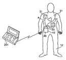
- FIG. 1shows a defibrillation system according to the present invention in a configuration for performing diagnostics and data uploading.
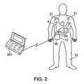
- FIG. 2shows the defibrillation system according to the present invention during use in connection with monitoring and treating a patient.
- FIG. 3shows an electrode harness used with the defibrillation system of FIGS. 1 and 2 .
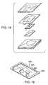
- FIG. 4shows a view of a sensing electrode and applicator used in the electrode harness of FIG. 3 .
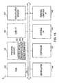
- FIG. 5shows an application tray used to apply sensing electrodes to a patient's body.
- FIG. 6shows defibrillation energy having a bi-phasic waveform which is generated by the defibrillation system of the present invention.
- FIG. 7Ashows a front view of a wearable defibrillator used in the system shown in FIGS. 1 and 2 .
- FIG. 7Bis an exploded view showing the mechanical construction of the wearable defibrillator of the present invention.
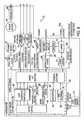
- FIG. 8shows a functional block diagram of the defibrillator shown in FIG. 7A .
- FIG. 9shows a “221” capacitor configuration.
- FIG. 10shows a “2111” capacitor configuration.
- FIG. 11shows a “11111” capacitor configuration.
- FIG. 12is a flow diagram depicting general operation of the wearable defibrillator of FIG. 7A .
- FIG. 13is a block diagram of electrical circuitry used in the preferred embodiment of the present invention to implement the functions shown in FIG. 8 .
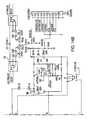
- FIG. 14shows the layout of FIGS. 14A-14C .
- FIGS. 14A-14Cshow details of a capacitor switching circuitry used in the preferred embodiment of the present invention.
- FIG. 15is a block diagram of a base station used in the system of FIGS. 1 and 2 .
- FIG. 16is a block diagram showing a preferred algorithm used by the present invention to perform ECG analysis on received patient information.
- FIG. 17is an exploded view of the primary power supply used in the defibrillator of the present invention.
- FIG. 18shows a view of an alternative electrode and applicator configuration that may be used in the present invention that uses selectively applied adhesives in the applicators.
- FIG. 19is a view of an alternative electrode configuration that may be used in the present invention.
- FIGS. 20A and 20Bare views of an alternative electrode configuration that may be used in the present invention.
- FIGS. 21A and 21Bare views of an alternative electrode configuration that may be used in the present invention.
- FIG. 22shows a view of an alternative electrode configuration that may be used in the present invention.
- FIG. 23shows a view of an alternative electrode configuration that may be used in the present invention.
- FIG. 24shows an embodiment of an electrode in which an adhesive surface is covered with a pull-tab covering to allow the patient to place the electrode on the patient's skin and then to pull the tab to expose the adhesive surface.
- defibrillation system 1is directed to a defibrillation system for use in treating patients who have suffered from cardiac arrhythmias.
- a representative embodiment of the inventionis shown in FIGS. 1 and 2 .
- defibrillation system 1is comprised of base station 2 , electrode harness 4 , personal computer 6 , patient simulator 7 , central repository 9 , and wearable defibrillator 10 .
- base station 2electrode harness 4
- personal computer 6personal computer 6
- patient simulator 7patient simulator 7
- central repository 9central repository
- wearable defibrillator 10wearable defibrillator
- Defibrillator 10is capable of interfacing either to base station 2 , as shown in FIG. 1 , or to electrode harness 4 , as shown in FIG. 2 .
- both electrode harness 4 and base station 2include physical connector identifiers at their respective interfaces to defibrillator 10 .
- defibrillator 10is able to determine both the type of interfaced device (i.e., a base station or electrode harness) and the identity of a particular interfaced device (i.e., one electrode harness as opposed to another), and then to react accordingly
- Electrode harness 4includes one or more sensing electrodes 31 which interface to patient 12 , and which are used both to monitor the patient and to transmit defibrillation energy to the patient.
- sensing electrodes 31comprise segmented electrodes since these require the most description.
- Defibrillation energywhich can comprise an electric signal having a bi-phasic waveform, a mono-phasic waveform, or a truncated exponential waveform, is generated by defibrillator 10 in the event that predetermined conditions have been detected in the patient. These predetermined conditions include whether the patient has suffered a cardiac arrhythmia, whether the patient is conscious, as well as other conditions, such as patient impedance, that are monitored by sensing electrodes 31 .
- Defibrillator 10is also capable of providing pacing impulses and tactile stimulation signals to the patient via electrode harness 4 .
- the tactile stimulation signalsalert the patient to abnormal cardiac activity in the patient, whereas the pacing impulses stimulate contractions of the patient's heart.
- electrode harness 4is being worn by the patient, data may be transmitted directly from defibrillator 10 to personal computer 201 via non-contact interface 16 .
- base station 2When defibrillator 10 is interfaced to base station 2 , as shown in FIG. 1 , base station 2 is able to perform diagnostics on the defibrillator, to reprogram the defibrillator, and to retrieve data stored in the defibrillator. Such data can include an operational history of the defibrillator, information concerning the patient's cardiac activity, and the like. All or some of this retrieved data may be transmitted, via personal computer interface 14 , to personal computer 6 for display and/or processing.
- Data retrieved by base station 2 from defibrillator 10may be transmitted to central repository 9 via external data link 17 .
- Central repository 9preferably stores this data, together with patient and defibrillation information corresponding to a plurality of other patients, all of whom use the same type of defibrillator.
- a personal computer 19is in communication with central repository 9 . This personal computer may be used to analyze the patient and defibrillation information received from defibrillator 10 in view of corresponding information from the plurality of other patients, and, if desired, to provide the results of this analysis back to base station 2 .
- defibrillator 10also includes a link to patient simulator 7 .
- Patient simulator 7comprises test equipment which simulates bodily functions and characteristics of a patient, including cardiac activity and thoracic impedance.
- defibrillator 10monitors patient simulator 7 in much the same way that defibrillator 10 monitors a patient and, in a case that predetermined conditions have been detected in patient simulator 7 , transmits defibrillation energy to patient simulator 7 .
- patient simulator 7also simulates patient responses to the defibrillation energy provided by defibrillator 10 and provides response information back to defibrillator 10 . This response information may be transmitted to, and analyzed by, base station 2 , and then provided to any one or more of central repository 9 , computer 6 , or defibrillator 10 .
- FIG. 3shows a close-up view of electrode harness 4 .
- Electrode harness 4is preferably disposable and, in preferred embodiments of the invention, can be worn for approximately 2 to 7 days or longer for a cumulative period of 1 week to 12 months.
- electrode harnessmay include a means for defibrillator 10 to determine how long electrode harness 4 has been connected thereto.
- electrode harness 4includes an identification resistor (not shown) as its physical connector identifier. Defibrillator 10 measures the resistance across this resistor and then starts a countdown, after which defibrillator 10 notifies the patient that it is time to change the electrode harness.
- each electrode harnessmay include a different, unique resistance associated therewith. Defibrillator 10 may measure this resistance by passing a current therethrough and, in this manner, determine the identity of an interfaced electrode harness.
- electrode harness 4includes power supply 20 , connector 21 , non-electrically conductive padding 22 and 24 , electrical leads (or “lines”) 26 , 27 , 29 and 30 , and sensing electrodes 31 .
- Sensing electrodes 31comprise the defibrillator's interface to the patient. Specifically, sensing electrodes 31 attach to the patient so as to monitor the patient, transmit tactile stimulation energy, and to transmit defibrillation energy to the patient under appropriate circumstances.
- Each electrodemay comprise a single layer of conductive material. In preferred embodiments of the invention, however, each electrode is multi-layered as shown, for example, in the cross-sectional view of electrode 31 a in FIG. 4 . In the example shown in FIG. 4 , electrode 31 a includes three layers, namely top cover assembly 32 , conductor/wire assembly 33 , and skin interface 32 .
- Skin interface 32contacts directly with the patient's skin and comprises a layer of material, such as a hydrogel, that is capable of transmitting defibrillation energy to the patient without causing substantial irritation or harm to the skin.
- a layer of materialsuch as a hydrogel
- conductive screens or meshescan be used in addition to or in place of hydrogel. These screens or meshes may be used in combination with a cream, such as a hydrating cream or a skin healing cream. Such creams also may be applied to the patient's skin before attaching the electrodes thereto.
- Conductor/wire assembly 34contacts to conductor/wire assembly 34 , which can be either substantially coextensive with, or smaller than, skin interface 32 .
- Conductor/wire assembly 34includes conductive layer 34 a , wire connection 34 b , wire 34 c , and sealing layer 34 d .
- Conductive layer 34 apreferably comprises a silver/silver chloride polymer base ink silk-screened onto a layer of Tyvek (used as an insulator and as a carrier) which is die-cut and folded.
- Tyvekused as an insulator and as a carrier
- a wire with a welded washeris then attached to conductive layer 34 a by means of a washer (tin plated nickel) and eyelet (a hollow rivet that is crimped in order to hold the assembly together). Insulating tape is then wrapped around this connection in order to reduce corrosion.
- conductor 34 amay comprise conductive metal such as tin, silver, gold, copper, salts or oxides of these conductive metals, carbon, a substrate which has been coated with a conductive compound (e.g., polytetrafluoroethylene), an ink silkscreened on a carrier, metallized cloth, solid metal or carbon grid, foil, plate, etc.
- Conductor 34preferably has a thickness which is sufficient to transmit at least ten successive defibrillation energy signals having peak amplitudes of 23 amperes for a duration of 10.75 msec each.
- Top cover assembly 33includes foam insulating layer 33 a and wearable adhesive layer 37 .
- Adhesive 37which can comprise an adhesive material fixed to a backing, such as tape or the like, is disposed adjacent to conductor 34 and/or skin interface 32 and is used to attach electrode 31 a to the patient's skin. In preferred embodiments of the invention, adhesive 37 may also be temperature sensitive, meaning that adhesion thereof increases or decreases in response to temperature variations. Adhesive 37 is preferably non-conductive.
- Adhesive 37should also be adapted for long-term wear. To this end, an adhesive having a high moisture vapor transmission rate (“MVTR”) of approximately 300 to 1500 g/m 2 /day is suitable for use with the invention. By virtue of this feature of the invention, the adhesive is made breathable, meaning that it permits air to be transmitted therethrough to the patient's skin. This increases the amount of time an electrode may be worn without causing substantial harm to the patient's skin. Adhesive 37 should also be sufficient to adhere to the patient's body in the face of normal movements or muscle contractions and in the face of normal water exposure such as might occur during bathing or sweating. However, adhesive 37 should not be so strong as to cause substantial discomfort during removal of an electrode. To this end, adhesive 37 preferably has a peel strength of 500 g/cm or less.
- Applicator 35includes two layers—a bottom layer having cut-outs 35 a and a top layer having an adhesive 35 b . Cut-outs 35 a limit the amount of adhesive that contacts the top side of the electrode.
- Release liner assembly 36includes cut-out 36 a on upper layer 36 b (closest to the hydrogel) which causes only a portion of urethane bottom layer 36 c to come into contact with upper layer 36 b .
- This configuration of release liner assembly 36particularly cut-out 36 a , allows bottom layer 36 c to be removed first from an electrode, followed by upper-layer 36 b , without causing any separation of the electrode from the applicator assembly.
- cut-outs 35 a on applicator 35 bfacilitate removal of applicator 35 b from top cover assembly 35 without causing harm to the electrode.
- FIG. 18An alternative electrode configuration to that shown in FIG. 4 is shown in FIG. 18 .
- FIGS. 19 to 24show additional alternative electrode configurations.
- FIG. 19shows a finger-patterned electrode 200 comprising a conductive adhesive polymer layer 220 , a carbon sheet 240 , and a medical adhesive carrier 260 , covering and extending beyond the edges of the polymer layer 220 and the carbon sheet 240 .
- a metal sheet or a metal fabricmay replace carbon sheet 220 .
- FIG. 20A and FIG. 20Bshow a rectangular electrode 300 comprising metal foil sheet 320 , pressure pad backing 340 and medical adhesive carrier 360 , covering and extending beyond the edges of the metal foil sheet 320 and the pressure pad backing 340 .
- the front surface of metal foil sheet 320comes in contact with patient's skin 380 and pressure pad backing 340 contacts the back surface of metal foil sheet 320 and keeps metal foil sheet 320 in close contact with skin 380 .
- a pressure padis a unit which can be deformed by pressure applied in the direction perpendicular to the skin. By maintaining a thickness that is less than a free dimension, pressure in the pad is assured.
- Medical adhesive carrier 360contacts pressure pad backing 340 .
- a metal fabricreplaces metal foil sheet 320 .
- FIGS. 21A and 21Bshow rectangular electrode 400 comprising metal foil sheet 420 , pressure pad backing 440 , stiffener 460 , and medical adhesive carrier 480 .
- the front surface of metal foil 420is in contact with skin 490 ; the front surface of pressure pad 440 is in contact with the back surface of metal foil 420 ; the front surface of stiffener 460 is in contact with the back surface of pressure pad 440 ; and medical adhesive carrier 480 is in contact with stiffener 460 and covers and extends beyond the edges of all other layers ( 420 , 440 , and 460 ).
- Stiffener 460comprises a material which will resist bending, and stiffener 460 is used to transmit force into the electrode area.
- stiffener 460comprises a thin plastic material with an area that is slightly larger than areas of metal foil sheet 420 and pressure pad backing 440 .
- a metal fabricreplaces metal foil sheet 420 .
- FIG. 22shows electrode 500 with alternating strips of active areas 520 and space 540 for breathing.
- Each active area 520comprises a metal foil sheet and a pressure pad backing. The strips of active areas 520 are in contact with stiffener 560 , and stiffener 560 is in contact with medical adhesive carrier 580 .
- a metal fabricreplaces the metal foil in each active area 520 .
- each active areacomprises a metal foil sheet or a metal fabric, a pressure pad backing and a stiffener. The back surfaces of the active areas are in contact with a medical adhesive carrier.
- FIG. 23show electrode 600 with multiple small square-shaped active areas 620 .
- active areas 620are spaced for breathing.
- Each active area 620comprises a metal foil and a pressure pad backing.
- the back surfaces of active areas 620are in contact with the front surface of stiffener 640
- medical adhesive carrier 660is in contact with the back surface of stiffener 640 .
- a metal fabricreplaces the metal foil sheet.
- each active areacomprises a metal foil sheet or a metal fabric, a pressure pad backing and a stiffener. Back surfaces of the active areas are in contact with a medical adhesive carrier.
- FIG. 24shows an embodiment of the electrode in which the adhesive surface is covered with a pull-tab covering to allow the patient to place the electrode on the skin and then pull the tab to expose the adhesive surface and maintain the electrode in place.
- a conductive portion of each sensing electrodewhich in this case are segmented electrodes, preferably has a surface area that is roughly 8 to 10 cm 2 ; although other dimensions may be used.
- the present inventiontakes advantage of “spreading resistance” in the patient's bodily tissue so as to permit this reduction in the surface area of the conductive portion each electrode.
- Spreading resistanceis a property of human tissue which causes defibrillation energy (or any other electric signal for that matter) applied to the patient's skin to spread outward over the skin and downward and outward through the patient's tissue.
- the present inventioncompensates for this by placing sensing electrodes 31 in a geometric pattern such that the interaction between diffusing current from each sensing electrode results in an accumulation of spreading current in areas between sensing electrodes 31 .
- the resultis that an effective area is created in which current densities in the path between groups of sensing electrodes (e.g., sensing electrodes 31 a , 31 b and 31 c shown in FIG. 3 ) are similar to that of a large electrode having a perimeter equal to an outer perimeter of all of the sensing electrodes in the group.
- a similar effectmay be achieved through random placement of the electrodes on the patient.
- the present inventionis able to create a “virtual” conductive surface using relatively small electrodes.
- the virtual conductive surfacecan be significantly larger than a combined conducive area of the individual sensing electrodes. This also contributes to a lower impedance for a combined surface area of the sensing electrodes than would be the case for a continuous electrode having a similar surface area.
- Each of sensing electrodes 31may be shaped so that the conductive portion thereof has a perimeter which is greater than a circumference corresponding to a radius of the electrode. That is, since charge tends to migrate to the perimeter of an electrode, the present invention attempts to maximize the perimeter of each electrode, particularly conductive surfaces thereof, thereby increasing the amplitude of the defibrillation energy that the electrode can handle without causing substantial burns to the patient. Examples of electrodes with such a perimeter include star-shaped electrodes, square electrodes, swirled-shaped electrodes, etc. It is, however, noted that conventional circular electrodes may be used in conjunction with the present invention as well.
- sensing electrodes 31should be placed within a “thoracic window” on the patient's body.
- a thoracic windowis defined as an area of the patient's body which is suitable for placing electrodes so as to optimize delivery of defibrillation energy to the patient's heart, and is described in an article by Geddes et al. the American Heart Journal, volume 94, page 67 (1977), the contents of which are hereby incorporated by reference into the subject application as if set forth herein in full.
- electrodesare typically placed underneath the patient's left rib cage and over the patients right shoulder area.
- electrodesare typically placed on a patient's lower left back and left front.
- the sensing electrodesare placeable over the thoracic window either randomly or in a geometric pattern which is sufficient to cover a large enough area of the patient's myocardium to cause adequate defibrillation upon application of defibrillation energy.
- Electrodes 31can be attached or placed in contact with the skin by various methods. Proper defibrillation requires that the electrodes be in close contact with the patient's skin, in addition to being placed in an appropriate location within the patient's thoracic window area. Preferably, the electrode are attached to the patient's skin using an adhesive thereon, as described in more detail below. However, other attachment means are possible. For example, a thoracic wrap made out of cotton or spandex can be used to assure proper placement of the electrodes and good contact between the electrodes an the skin.
- each sensing electrode in a group(e.g., the group of electrodes 31 a , 31 b and 31 c ) should be placed within a predetermined distance of other sensing electrodes in the group.
- each sensing electrode in each group of electrodesis separated from other sensing electrodes in that same group by between 0.5 and 3 times an effective diameter of each electrode, where the effective diameter corresponds to the farthest distance between two points on the electrode.
- electrode harness 4includes non-electrically conductive pads 22 and 24 (i.e., the passive areas), on which groups of sensing electrodes can be mounted in predetermined geometric configurations. For example, as shown in FIG.
- sensing electrodes 31 a , 31 b and 31 care mounted on pad 22 in a triangular configuration, while sensing electrodes 31 d , 31 e , 31 f and 31 g are mounted on pad 24 in a rectangular configuration.
- FIG. 3shows only two geometric arrangements for sensing electrodes 31 , the invention is not limited to these. Rather, any geometric arrangement may be utilized, including, but not limited to, a checkerboard pattern, swirl patterns, interlocking patterns, star patterns, crescent patterns, E-shaped patterns, F-shaped patterns, L-shaped patterns, X-shaped patterns, H-shaped patterns, O-shaped patterns, C-shaped patterns, etc.
- the electrodesmay be arranged in a random manner as well.
- pads 22 and 24are flexible so as to facilitate placement of sensing electrodes 31 on contours of the patient's body. It is noted, however, that pads 22 and 24 need not be flexible. Rather, an adhesive tape can be used in place of pads 22 and 24 or, alternatively, in addition to pads 22 and 24 . As still another alternative, pads 22 and 24 can be used selectively in electrode harness 4 , meaning that pads can be used to mount some of sensing electrodes 31 and not others. In fact, this is the case in the representative embodiment of the invention depicted in FIG. 3 . That is, in the embodiment shown in FIG.
- segmented electrodesis not mounted on a pad, but rather “floats”, meaning that it can be mounted anywhere on a patient's body, constrained, of course, by the length of its electrical lead 30 .
- electrode 31 hdoes not provide the defibrillation energy to the patient, but rather is used only to monitor the patient's ECG.
- all electrodesmay float in the same manner as sensing electrode 31 h .
- the inventionmay include an applicator tray, such as tray 39 shown in FIG. 5 , having cups 40 which arrange the electrodes in geometric patterns so as to ensure accurate placement within the patient's thoracic window. That is, the applicator tray ensures that the electrodes will be spatially arranged in the manner described above so as to take advantage of human tissue's spreading effect.
- electrodes 31may include a hydrogel or other conductive material on a surface thereof which comes into contact with the patient's skin, i.e., on the skin interface of the electrode.
- the hydrogelis electrically conductive, thereby permitting transmission of the defibrillation energy to the patient, but has a relatively low ion concentration that is low enough so as to not to cause substantial skin irritation.
- the conductivity of the hydrogelis variable based, e.g., on temperature, etc.
- the hydrogelpreferably has a relatively high MVTR, thereby making the hydrogel breathable. As was the case above with respect to adhesive 37 , this reduces skin irritation caused by wearing the electrodes, and thus increases the amount of time that the electrodes can be worn.
- Hydrogels or other conductive materials used with conventional ECG electrodesmay be used in the present invention, since the deleterious effects of such materials will be countered by the present invention for reasons described both above and below.
- conductive materials which meet the above qualificationsinclude electrolytes, such as sodium chloride (NaCl), potassium chloride (KCl), or lithium chloride (LiCl).
- electrolytessuch as sodium chloride (NaCl), potassium chloride (KCl), or lithium chloride (LiCl).
- Currently preferred hydrogel materialsinclude hydrophilic polymers, such as karaya gum, gum acacia, locust bean gum, polysaccharide gum, modified polysaccharide, or polyacrylamide.
- a hydrating agentsuch as water or polyhydric alcohol (e.g., glycerine, propylene glycol, triethylene glycol, glycerol, etc.) may also be included in the conductive material.
- wateris typically present at a concentration from about 1% to 60% by weight, whereas polyhydric alcohol is typically present at a concentration from about 10% to 50% by weight.
- the electrode interface to the skinmay include, instead of or in addition to a hydrogel, a mesh, screen, or other porous material. These elements are conductive and, due to their porous nature, allow air to pass therethrough to the patient's skin. As was the case with the hydrogel described above, this feature of the invention provides for prolonged wearability of the electrodes.
- the hydrogel on each sensing electrodemay also include a therapeutic or prophylactic agent which reduces skin irritation caused by the electrode, and/or which promotes healing of wounds or skin irritation that may be caused by the sensing electrodes.
- a therapeutic or prophylactic agentwhich reduces skin irritation caused by the electrode, and/or which promotes healing of wounds or skin irritation that may be caused by the sensing electrodes.
- Such an agentmay be applied directly to each electrode, or capsules which release the agent in response to the defibrillation energy may be applied to the electrode.
- a therapeutic or prophylactic agentmay also be included on each of pads 22 and 24 in order to promote skin health.
- Agents which render the patient's skin poroussuch as keratolytic agents (e.g., salicylic acid) or rubefacient (e.g., methyl salicylate) may be included on each electrode or pad so as to facilitate transmission of the therapeutic or prophylactic agent into the skin and/or to permit use of low water content hydrogels.
- keratolytic agentse.g., salicylic acid
- rubefaciente.g., methyl salicylate
- therapeutic or prophylactic agentsexamples include moisturizers, emollients, bactericides, mold inhibitors, stabilizers or buffers to maintain a neutral PH and to reduce corrosion and skin sensitivity, gelation inhibitors (e.g., Mg(OAc) 2 ), healing agents, hormonal agents (e.g., hydrocortisone (steroids)), protective agents, etc.
- gelation inhibitorse.g., Mg(OAc) 2
- healing agentse.g., hydrocortisone (steroids)
- hormonal agentse.g., hydrocortisone (steroids)
- protective agentsetc.
- acceptable bactericides and mold inhibitorsinclude antibactierals, antiseptics, antifungals, boric acid, bacitracin, acriflavine, formaldehyde, gentian violet, mercuric sulfide, mercurochrome, neomycin, and iodine.
- acceptable stabilizersinclude oligo or polybasic organic acids and their salts (including chelating agents), polyethers, tartaric acid, citric acid, and n-alkyl sulfonate, where n is from 8 to 16 carbon atoms.
- acceptable healing agentsinclude allantoin, peruvian balsam, vitamin A, and vitamin B.
- acceptable protective agentsinclude benzoin, charcoal, talc, zinc oxide, and aloe vera. These therapeutic agents may be used both prior to use or after use to promote healing.
- the amount of therapeutic or prophylactic material usedcorresponds to an amount effective to reduce irritation, or to promote recovery of irritated skin.
- the therapeutic or prophylactic agentmay be in any form useful to achieve the intended purpose, including liquid solutions, creams, gels, solids, granules, powders or any other form, including microcapsules.
- the therapeutic or prophylactic agentmay be included as part of the electrode, e.g., incorporated in the conductive areas of the electrode, or incorporated in a passive area of the electrode array.
- the electrode arraymay comprise three areas: electrode areas, passive areas and areas containing the therapeutic or prophylactic material.
- the therapeutic or prophylactic materialmay be applied to the skin prior to attaching the electrodes (pre-treatment), or after the electrodes have been removed (post-treatment).
- skin irritationmay be reduced by including in the electrode array means for monitoring, controlling and/or correcting the skin environment in contact with the electrode array. For example, it is possible to monitor the electrode-to-skin PH, and adjust the PH accordingly.
- the electrodesmay comprise a multi-layered matrix for controlling ion flow between the skin and the electrode.
- non-segmented electrodeshaving conductive portions of less than 60 cm 2 and, in some cases, even to less than 30 cm 2 may be utilized.
- conductive portions of defibrillation electrodestraditionally, it was necessary for conductive portions of defibrillation electrodes to have a surface area of 60 cm 2 to 80 cm 2 in order to deliver a sufficient defibrillation energy to the patient.
- the present inventiontakes advantage of the “spreading resistance” effect described above so as to permit reduction in the surface area of each electrode.
- the features described herein with respect to sensing electrodes 31may also be used in conjunction with the non-segmented electrodes described herein.
- These featuresinclude, but are not limited to, using hydrogels having low ion concentrations, therapeutic and prophylactic agents, and/or high MVTRs, effecting electrode movement relative to the patient so as to reduce the deleterious effects of electrode-to-skin contact, etc., utilizing an adhesive designed for long-term wear, etc.
- the following monitoring and energy-transmitting functions described with respect to segmented electrodesmay also be used in conjunction with the non-segmented electrodes described herein.
- non-segmented defibrillation electrodesi.e., electrodes having a surface area of 60 cm 2 to 80 cm 2
- these aspectsinclude, but are not limited to, using the electrodes in conjunction with hydrogels having low ion concentrations, therapeutic and prophylactic agents, and/or high MVTRs, effecting electrode movement relative to the patient so as to reduce the deleterious effects of electrode-to-skin contact, etc., utilizing an adhesive designed for long-term wear, etc.
- the following monitoring and energy-transmitting functions described with respect to sensing electrodes 31may also be used in conjunction with the traditional non-segmented electrodes described herein.
- defibrillator 10may also be used with any type of commercially-available subcutaneous electrode as well. It is still further noted that the invention may include combinations of two or more of the foregoing types of electrodes.
- each group of electrodes and/or single electrodehas at least one electrical lead mechanically connected between its lead interface and power supply 20 .
- the leadscan be standard cables comprising electrically conductive wires sheathed in a flexible, protective material, e.g., a flexible plastic material.
- the wires used in the leadspreferably are able to carry repeated defibrillation impulses of at least 20 A for a 20 millisecond duration, and preferably have adequate insulation qualities satisfying a high potential test for about 1750 V.
- the cablespreferably are flexible, durable, soft and comfortable while having sturdy insulation.
- power supply 20includes base 180 , top 181 and, sandwiched therebetween, batteries 184 .
- Power supply 20is also comprised of connector 21 , which includes the physical connector identifier for electrode harness 4 , and which interfaces power supply 20 and electrical leads 26 , 27 , 29 and 30 to defibrillator 10 .
- connector 21includes socket 186 which receives the electrical leads via holes 185 .
- Socket 186fits within top 181 such that pin 188 on top 181 contacts with hole 190 on socket 186 . Socket 186 is shielded so as to protect signals being transmitted therethrough from batteries 184 . This shielding is tied to the “floating” ground in the battery and also to shields from the leads to the electrodes.
- each electrical leadis non-removably connected to connector 21 on power supply 20 , meaning that each lead is hard-wired to connector 21 or is otherwise connected to connector 21 in a way in which removal of the electrical leads from connector 21 will damage either one or both of these components. It is noted, however, that alternative embodiments of the invention are possible, in which each lead is removably connected to connector 21 .
- Power supply 20comprises the primary power cell for wearable defibrillator 10 .
- batteries 184comprise non-rechargeable lithium batteries (e.g., DL123A, size 2/3 A) which are capable of providing 2 to 7 days of normal operation of defibrillator 10 , including delivering at least six defibrillation energy (i.e., shocks) having peak currents of 23 A to the patient.
- the working voltage of power supply 20is preferably 3.3 to 6.6 V, with the maximum output being 6.6 V.
- power supply 20is made water-resistant by sealing power supply 20 within a silicone membrane (not shown) or the like.
- power supply 20may be made water-resistant by a number of other means as well. For example, it is possible to use a variety of other insulating materials in place of silicone. By sealing power supply 20 in this manner, it is possible to reduce the risk of unintended electric shock during activities, such as showering or the like.
- Each electrical lead on electrode harness 4has a length that is sufficient for each corresponding electrode or group of electrodes to be placed on the patient at a predetermined distance away from others of the electrodes or groups of electrodes.
- defibrillatoras opposed to solely ECG
- the inventionensures proper accumulation of current in areas between the sensing electrodes.
- the present inventionprovides an additional advantage in this regard in that groups of electrodes arranged in geometric patterns on the patient are movable relative to the patient in a manner which ensures that the geometric patterns are substantially retained, but are at different orientations relative to the patient.
- sensing electrodes 31 a , 31 b and 31 cit is possible to rotate pad 22 containing sensing electrodes 31 a , 31 b and 31 c on a patient such that pad 22 is still within the patient's thoracic window (e.g., either the apex-sternum thoracic window, the anterior-posterior thoracic window, or some combination thereof), but such that sensing electrodes 31 a , 31 b and 31 c do not contact the patient's skin at the same location.
- Random rotation or movementmay also be used to accomplish the same result. For example, in a case that electrodes 31 all float, random motion may be the best way in which to achieve the desired result.
- each sensing electrodes 31 , group of sensing electrodes, or individual non-sensing electrodesshould be rotated in the above manner roughly once every 12 hours to 7 days.
- sensing electrodes 31are capable of transmitting electrical signals from defibrillator 10 to a patient.
- These electrical signalsinclude, but are not necessarily limited to, defibrillation energy, tactile stimulation signals, pacing signals, and AC and DC signals used to measure a patient's skin and thoracic impedance.
- the same information used to measure the patient's thoracic impedancemay also be used to determine the patient's respiration and pulse rates.
- the defibrillation energypreferably has a bi-phasic waveform with two phases. These phases may have substantially equal durations or, alternatively, may have different durations, e.g., the first phase may be roughly 6 msec and the second phase may be roughly 4 msec.
- An example of a bi-phasic waveform having substantially equal durationsis shown in FIG. 6 (described below).
- the waveform of the defibrillation energymay also be mono-phasic, i.e., the waveform may comprise just the first one of the two phases shown in FIG. 6 , or may comprise a truncated exponential waveform.
- Monophasic waveformstypically require greater current, generally on the order of 15% to 20% greater, in order to achieve substantially the same effect as bi-phasic waveforms.
- the pacing impulsesthese preferably comprise waveforms having a low peak current of roughly 150 mA.
- Sensing electrodes 31are also capable of transmitting patient information from the patient to defibrillator 10 .
- This patient informationincludes, but is not limited to, information relating to the patient's skin and thoracic impedance, artifact noise in the patient's body (caused, e.g., by cardiopulmonary resuscitation, agonal breathing, seizures, patient handling, and ambulatory or vehicular motion), sensory stimulation signals from the patient, and the patient's ECG, including any cardiovascular signals evidencing abnormal heart activity.
- electrode harness 4preferably includes two independent differential channels, namely “ECG 1” and “ECG 2” shown in FIG. 3 , for measuring the patient's ECG.
- groups of electrodes 31 a , 31 b and 31 c and 31 d , 31 e , 31 f and 31 g comprising ECG 1both provide the defibrillation energy to the patient and monitor the patient's ECG, whereas electrode 31 h comprising ECG 2 is used solely for monitoring the patient's ECG.
- ECG 1serves as the primary monitoring channel for ECG analysis
- ECG 2serves as a backup for use in a case that ECG 1 is not operating or is not operating properly (e.g., if ECG 1 is relatively noisy).
- ECG 2can be used as a means of verifying the validity of an ECG obtained via ECG 1. That is, by comparing ECGs obtained from ECG 1 an ECG 2, it is possible to confirm the validity of the patient's ECG. It is also possible to confirm whether the electrodes are properly attached to the patient based on this comparison. As still another alternative, it is possible to “average” ECGs from ECG 1 and ECG 2, in order to obtain an averaged ECG for the patient, or to increase ECG resolution by using inputs from both ECG 1 and ECG 2. The use to which defibrillator 10 puts the ECG signal, as well as the other signals obtained via an electrode harness 4 , is provided in detail below.
- defibrillator 10provides several ways to measure the patient's thoracic impedance based on information received from sensing electrodes 31 .
- the patient's impedanceis determined directly by applying an AC or DC signal through an electrode, sampling data obtained from the electrode in response to the AC or DC signal, and analyzing the sampled data. More specifically, in preferred embodiments of the invention, this method of measuring the patient's thoracic impedance entails sampling such data from an electrode within 5 seconds of defibrillator power-on and then every 10 seconds for a 160 msec period at a sample rate of 4 msec or to continuously sample the impedance signal.
- Filteringis then performed on the sampled data so as to reduce the bandwidth of the sampled data to less than 10 Hz.
- the sampled datais then analyzed so as to provide a noise magnitude estimate for the signal and a frequency content of the signal.
- Subsequent processingis then performed to obtain a measurement of the patient's thoracic impedance by averaging all of the data samples in each 160 msec period. This averaging and filtering is performed in order to reduce the effects of artifact noise associated with CPR, muscle tremors, and agonal breathing. Of course, this processing occurs in defibrillator 10 , and not in electrode harness 4 .
- the patient's thoracic impedanceis also calculated by defibrillator 10 each time the defibrillation energy is transmitted to the patient.
- the patient's thoracic impedancemay be determined before, during and after transmission of defibrillation energy, based on patient information received from the electrodes in response to the defibrillation energy.
- defibrillator 10includes housing 40 , light emitting diode (hereinafter “LED”) 41 , visual indicator 42 , auditory indicator 44 , enunciator 46 , user interface 47 , communications link 49 , and connector 50 .
- FIG. 7Bis an exploded view showing the mechanical construction of the features shown in FIG. 7A . A description of these features of the invention is provided below.
- Housing 40is preferably small enough to make the defibrillator portable, and thus wearable, yet large enough to house the circuitry included within defibrillator 10 .
- housing 40can comprise a belt, or the like, which a patient can wear around his or her waist, chest, etc.
- housing 40comprises a rectangular casing that is roughly 6 inches in length, by 4 inches in width, by 2 inches in depth, or preferably 5.2 inches by 3.2 inches by 1.5 inches.
- housing 40is comprised of base 40 a and top 40 b .
- the preferred weight of defibrillator 10is approximately 1.5 pounds or preferably 1.0 pound or lighter.
- the inventionis able to achieve its small size by using high-energy capacitors (e.g., 500 ⁇ F, 400 ⁇ F, etc.) to store and deliver defibrillation energy, as described in more detail below.
- Connector 50 and communications link 49comprise external interfaces on defibrillator 10 .
- Connector 50is disposed on housing 40 so as to permit connection of defibrillator 10 to mating connector 21 on power supply 20 (see FIG. 2 ), and to permit connection of defibrillator 10 to corresponding mating connector 51 on base station 2 (see FIG. 1 ).
- connector 50preferably includes two high-speed data pins (not shown), which permits base station 2 to interface to defibrillator 10 at a same point that electrode harness 4 interfaces to defibrillator 10 .
- Communications link 49comprises a non-contact interface to personal computer 201 (see FIG.
- IRinfrared
- RFradio frequency
- Visual indicator 42comprises a liquid crystal display (hereinafter “LCD”) or the like (in preferred embodiments, a Standish 162SLC 2.times.16 dot matrix display), having two lines for displaying information, including text and errors, to a patient or to a clinician operating defibrillator 10 .
- LCDliquid crystal display
- Standish 162SLC 2.times.16 dot matrix displayhaving two lines for displaying information, including text and errors, to a patient or to a clinician operating defibrillator 10 .
- This informationcan include, but is not limited to, information concerning the patient's heart activity, such as the patient's ECG or the like; messages upon detection of abnormal activity in the patient's heart; statements indicating that the patient has been wearing electrode harness 4 for greater than a recommended period of time; instructions for the use of defibrillator 10 ; prompts for using defibrillator 10 ; errors that have occurred in defibrillator 10 ; messages transmitted to defibrillator 10 from an external location via base station 2 , personal computer 6 , or personal computer 201 ; an indication that one or more of sensing electrodes 31 have become detached from the patient; and an indication that defibrillator 10 cannot differentiate between artifact noise in a patient's body and a cardiac arrhythmia.
- the informationis displayed for about 15 seconds.
- one or more visual indicatorssuch as light emitting diode (hereinafter “LED”) 41 , may be provided on defibrillator 10 to indicate different operational states thereof.
- LED 41blinks when defibrillator 10 is operating normally, is off when defibrillator 10 is without power (including when power supply 20 has failed), and is continuously illuminated during power-up error detection diagnostics performed by defibrillator 10 .
- Auditory indicator 44comprises a speaker (in preferred embodiments, an MG Electronics MCS298 speaker) or the like, which provides verbal messages corresponding to information displayed on visual indicator 42 . These messages may be output in a variety of different languages on both visual indicator 42 and auditory indicator 44 .
- auditory indicator 41echos visual display 42 , and has a volume that is adjustable at least up to 60 or 70 decibels. Auditory indicator 44 may also be configured to provide additional sounds, such as tones, buzzing, beeping, etc. to indicate error conditions within defibrillator 10 .
- error conditionsinclude, but are not limited to, a low or drained power supply, improper attachment of sensing electrodes 31 to the patient, detachment of sensing electrodes 31 from the patient, and inoperability of defibrillator 10 .
- another auditory indicatorsuch as enunciator 46 , may also be included on defibrillator 10 .
- Annunciator 46is preferably separate from auditory indicator 42 , and produces a buzzing or other unique sound to indicate error conditions within defibrillator 10 , particularly a low or drained power supply.
- User interface 47comprises a response button, whereby a patient or clinician can provide an input to wearable defibrillator 10 simply by pressing the button.
- the response buttonis comprised silicone 47 a , button 47 b , paddle 47 c and foil 47 d .
- the response buttoncancels any upcoming defibrillation operation, meaning that, when pressed, the response button terminates a current defibrillation and, in some embodiments of the invention, disarms defibrillator 10 .
- the response buttonis relatively large, making it easily accessible to the patient, particularly through clothing and the like.
- defibrillator 10confirms when the response button has been pressed by issuing both audio and visual messages.
- the response buttonis pushed in response to, e.g., a “PLEASE RESPOND” verbal message so as to confirm patient consciousness or lack thereof.
- defibrillator 10also includes a cardiac event recording button which may or may not be separate from the response button, and which is pushed when the patient wants to record occurrence of a cardiac event. It is noted that these two functions are combined during a potential rescue situation; i.e., the patient will want to respond to the defibrillator's response requests at the same time, possibly recording the occurrence of a cardiac event. Combining these functions into a single button helps train the patient to habitually push the same button whenever there are requests from the defibrillator or cardiac events.
- FIG. 8is a system functional block diagram of defibrillator 10 .
- the hardware and software functional blocks shown in FIG. 8monitor and analyze patient information (e.g., the patient's ECG) received from electrode harness 4 in order to determine if a cardiac rhythm is life threatening and requires defibrillation, and also permits communication to base station 2 , personal computer 6 , and personal computer 210 .
- these blocks within defibrillator 10determine the patient's thoracic impedance based on information received from the patient via electrode harness 4 , and adjust the defibrillation energy accordingly.
- a predetermined thoracic impedance valuemay be stored in data logging memory block 57 . That predetermined thoracic impedance value may then be retrieved and used to adjust the defibrillation signal.
- defibrillator 10comprises auditory indicator 44 , visual indicator 42 , LED 41 , user interface 47 , and enunciator 46 . Descriptions of these features of the invention were provided above and, therefore, will not be repeated here. It is worth noting, however, that enunciator 46 receives power from backup battery 54 , which is rechargeable, and which is independent of the primary source of power (i.e., power supply 20 ) for defibrillator 10 . Backup battery 54 provides power to enunciator 46 in the event that power supply 20 fails, thereby giving enunciator 46 the ability to warn the patient in such an event.
- backup battery 54provides power to enunciator 46 in the event that power supply 20 fails, thereby giving enunciator 46 the ability to warn the patient in such an event.
- Defibrillator 10also includes patient measurements block 56 , data logging memory block 57 , accessory communications block 59 , real time clock (hereinafter “RTC”) 60 , RTC/RAM backup battery 61 , which may or may not be separate from backup battery 54 , and signal generator 62 .
- signal generator 62comprises processing block 64 , defibrillation control block 66 , discharge/protection switches 67 , capacitors 69 , charger 70 and charge control block 71 .
- the present inventionincludes the forgoing blocks in signal generator 62 , any combination of hardware and/or software which effects the same function as these features can be employed in the practice of the present invention.
- RTC 66maintains the current date and time, receiving power from rechargeable RTC/RAM backup battery 61 when defibrillator 10 is powered-off.
- RTC 60is a Dallas 1306 serial RTC, which is able to maintain the correct time and date for up to 30 days without connection to power supply 20 .
- RTC/RAM backup battery 61also provides power to a memory (e.g., a RAM (not shown)).
- Accessory communications block 59performs any filtering and protocol conversion necessary to enable transmission of data between defibrillator 10 and base station 2 , personal computer 6 and/or personal computer 210 .
- Patient measurements block 56comprises analog signal conditioning hardware which filters and digitizes ECG signals, thoracic impedance measurements, and electrode-to-skin impedance measurements received via electrode harness 4 , and which transmits the resulting data to processing block 64 .
- Patient measurements block 56also receives information from an accelerometer, described below, relating to the patient's motion, and provides this information to processing block 64 .
- Data logging memory block 57stores both the operational history of defibrillator 10 and information relating to the patient. More specifically, data logging memory block 57 stores abnormal heart activity of the patient; the patient's ECG before, during and after application of defibrillation energy; an indication that the patient has been trained for use with defibrillator 10 ; analyzed ECG conditions; ECG markings, including defibrillation synch, external pace pulse, high slew rate, and saturation; patient thoracic and electrode-to-skin impedance measurements over time; voice, tone, and buzzer prompts; displayed messages; information concerning patient interaction with the defibrillator 10 (e.g., if and when the patient has pressed the response button); transmitted defibrillation waveform measurements, including current and voltage versus time; execution time measurements of defibrillator 10 for use in determining if defibrillator 10 operated as expected; detected operational errors of defibrillator 10 (including a type of error, persistence
- data logging memory blockessentially stores any information provided to, or transmitted from, defibrillator 10 over a predetermined span of time, such as two days.
- This datais preferably stored in a log format and includes time data specifying a time at which each event occurred.
- embedded in the dataare validation and synchronization mechanisms for use in detecting areas of corrupted or missing data.
- data logging memory block 57has a capacity (e.g., 24 megabytes or 48 megabytes) which is sufficient to record the foregoing information over a 48 hour period of continuous use of defibrillator 10 .
- a capacitye.g., 24 megabytes or 48 megabytes
- data logging memory block 57is removable, and can be transferred to the base station or to an external location at which point data stored therein may be downloaded.
- Signal generator 62generates, based on patient impedance data provided from patient measurements block 56 , defibrillation energy which preferably has a bi-phasic waveform may have two phases with substantially identical durations, different durations, or a first phase with a longer duration than a second phase, and having relatively low peak amplitudes over a patient impedance range.
- defibrillation energywhich preferably has a bi-phasic waveform may have two phases with substantially identical durations, different durations, or a first phase with a longer duration than a second phase, and having relatively low peak amplitudes over a patient impedance range.
- a mono-phasic waveform or a truncated exponential waveform having similar characteristicsmay also be used.
- FIG. 6shows a representative example of defibrillation energy generated by signal generator 62 .
- the amplitude at the end of the pulseis 60 to 80% of its initial value.
- the example shown in FIG. 6merely representative, and waveforms having different values can also be generated by the present invention.
- the duration of each phase of a bi-phasic waveformmay be between 4.5 and 6.4 msec.
- the waveform corresponding to the defibrillation energypreferably also has a substantially consistent tilt, as shown in FIG. 6 .
- the tilt of the defibrillation energyis between 53% and 79%.
- the present inventionprovides a way in which to alter this tilt using capacitors 69 .
- capacitors 69store energy which is discharged to the patient via discharge/protection switches 67 in the form of the foregoing defibrillation energy. This energy is discharged as a waveform having the foregoing characteristics.
- the tilt of the waveformi.e., the rate of the waveform's exponential decay
- the tilt of the waveformis determined by the “RC” time constant .tau. of the circuit used to generate the waveform.
- circuit's time constant .tau.may be altered by switching capacitors 69 , as described below, so as to alter the overall, combined capacitance value of capacitors 69 .
- switching capacitors 69in this manner, it is possible to vary the tilt of the waveform and the achieve a low-current waveform.
- the energy for defibrillation energyis discharged by capacitors 69 only in the case that a life-threatening cardiac arrhythmia is detected in the patient (as determined by comparing the patient's ECG to pre-stored patient parameters), the patient is deemed to be unconscious (as determined, e.g., by the patient's response, or lack thereof, to messages provided by auditory indicator 44 , visual indicator 42 . and enunciator 46 ), and the patient's thoracic impedance is within a predetermined range. In preferred embodiments of the invention, this range is between 15 ohms and 200 ohms. The process of determining whether and when to transmit defibrillation energy to a patient is described in more detail below.
- One (or more) of capacitors 69is also used to provide the above-noted tactile stimulation signal to the patient.
- the tactile stimulation signalmay be used to alert the patient of the occurrence of a cardiac event, and may vary based on the patient and based on which time it is administered to the patient in response to a message from the defibrillator. That same capacitor may also be used to deliver a pacing signal to the patient's heart in order to stimulate normal contractions thereof.
- the inventionpreferably includes 5 capacitors having capacitances of 500 ⁇ F (350 V) each; although capacitors having other capacitances may be used as well.
- the capacitorsare switchable into the “221” configuration shown in FIG. 9 , in which there are two sets of parallel capacitors in series with a single capacitor; the “2111” configuration shown in FIG. 10 , in which there is one set of parallel capacitors in series with three single capacitors; and the “11111” configuration shown in FIG. 11 , in which there are five single capacitors in series.
- the higher the impedance of the patientthe lower the peak current that is required for the defibrillation energy (a lower tilt is also required at higher impedances).
- the 11111 capacitor configurationmay be used to generate defibrillation energy having a maximum peak current of 15 A.
- the 221 capacitor configurationmay be used to generate defibrillation energy having a maximum peak current of 21 A.
- Table 1shown below, provides values for I max+ , I avrg+ , I final , t max+ , t switch , and t max ⁇ (see FIG. 6 ) for defibrillation energy for patients having impedances of 40, 60, 80 and 120 ohms. These values are merely representative of a particular case, and other values, of course, may be substituted therefor. In this regard, as noted above, the duration of each phase is roughly between 4.5-6.5 msec, and the peak current is roughly between 12 and 25 A.
- the inventionmay also include a resistor, placed in series with the capacitors. Due to the resistor's effect on the circuit's time constant, the resistor has the effect of “smoothing”, i.e., decreasing the tilt of, the waveform of the defibrillation energy. In this regard, generally speaking, an increase in the resistance of the resistor decreases the tilt of the waveform.
- the inventionmay include a single capacitor and one or more switchable resistors to achieve the effect of varying the circuit's time constant and thereby varying the waveform of the defibrillation energy.
- discharge/protection switches 67control delivery of the defibrillation energy from capacitors 69 to the patient.
- Discharge/protection switches 67are controlled by defibrillation control block 66 which, in turn, is controlled by processing block 64 .
- processing block 64commands defibrillation control block 66 to open discharge/protection switches 67 , thereby providing protection from unwanted electric signals.
- processing block 64determines that defibrillation energy is to be transmitted to the patient, processing block 64 immediately commands defibrillation block control block 66 to close discharge/protection switches 67 , thereby providing the energy to the patient.
- one of capacitors 69is also able to transmit tactile stimulation and pacing signals to the patient.
- processing block 64issues a command to defibrillation control block 66 which, in response, may switch one of discharge protection switches 67 so as to output a signal from only one of capacitors 69 .
- defibrillator control block 66also monitors discharge/protection switches 67 and provides the results thereof to processing block 64 .
- Charger 70controls charging of capacitors 69 from power supply 20 , the input of which is labeled 20 a in FIG. 8 .
- charger 70comprises hardware which transfers energy from power supply 20 to capacitors 69 .
- Charger control block 71controls charger 70 in response to commands received from processing block 64 so that capacitors 69 charge to a level commanded by processing block 64 .
- processing block 64may issue commands to charge capacitors 69 to one of a plurality of different levels depending on a determined type of arrhythmia, e.g., ventricular fibrillation versus ventricular tachycardia.
- Processing blockmay also issue commands to charge processing block 69 based on a type of signal to be transmitted, e.g., defibrillation energy, a pacing impulse, or a tactile stimulation signal.
- Processing block 64can comprise a microprocessor, controller, or the like, as described below, which includes an internal program memory (not shown in FIG. 8 ).
- This memoryis used to store software modules comprised of process steps that are executable by processing block 64 . Specifically, process steps in these modules are executable to control operation of defibrillator 10 based on input received from a patient or, alternatively, from base station 2 (see FIG. 1 ).
- These software modulescomprise input/output (hereinafter “I/O”) module 80 , including communications submodule 81 therein, data recording module 82 , diagnostics module 84 , defibrillation control module 86 , ECG analysis module 87 , user interface protocols 89 , and master control module 90 .
- I/Oinput/output
- I/O module 80preferably comprises a BIOS module which controls the transfer of data between software modules running within processing block 64 and hardware components within defibrillator 10 . I/O module 80 also controls communications between processing block 64 and auditory indicator 44 , visual indicator 42 , LED 41 , and user interface 47 . To this end, the invention includes user interface protocols 89 , between master control module 90 and I/O module 80 . User interface protocols 89 comprise command sequences for controlling transmission of various prompts, such as tones, verbal messages, or the like, to the user via auditory indicator 44 , visual indicator 42 , and LED 41 in response to detected events, such as a cardiac arrhythmias or the like.
- user interface protocols 89include command sequences for controlling receipt of signals input by the user via user interface 47 (i.e., the response button).
- Communications submodule 81controls communications between processing block 64 and an interfaced device, such as electrode harness 4 or base station 2 , via accessory communications block 59 .
- Processing block 64also executes a low-level, run time executive (hereinafter “RTE”) module (not shown), which supports communication between the various software tasks running in processing block 64 .
- RTErun time executive
- ECG analysis module 87comprises process steps which monitor the patient for a predetermined condition based on information provided through electrodes 31 .
- ECG analysis moduleanalyzes the patient's ECG and impedance data provided from sensing electrodes 31 (via patient measurements circuit 56 ), together with other information provided from the patient, including artifact noise and patient motion, in order to determine whether, when, and what types of arrhythmias are present in the patient's ECG.
- ECG analysis module 87performs any necessary signal processing on the patient's ECG and thoracic impedance data in order to remove any extraneous data such as may be present due to noise in the patient's body, including artifact noise or noise caused by patient motion.
- ECG analysis module 87compares the patient's ECG and thoracic impedance data to the patient parameters stored in data logging memory block 57 (e.g., the patient's thoracic impedance range and ventricular fibrillation and ventricular tachycardia rates at which defibrillation, pacing or cardio (described below) signals should be administered) in order to determine whether an arrhythmia has occurred.
- the patient parameters stored in data logging memory block 57e.g., the patient's thoracic impedance range and ventricular fibrillation and ventricular tachycardia rates at which defibrillation, pacing or cardio (described below) signals should be administered
- ECG analysis module 87determines that an arrhythmia has occurred, ECG analysis module 87 analyzes the patient's ECG and the patient parameters in order to determine the type of arrhythmia, i.e., whether the arrhythmia comprises ventricular fibrillation, ventricular tachycardia, asystole, bradycardia, or indioventricular rhythms, and whether defibrillation energy should be transmitted to the patient in response to the arrhythmia.
- the type of arrhythmiai.e., whether the arrhythmia comprises ventricular fibrillation, ventricular tachycardia, asystole, bradycardia, or indioventricular rhythms, and whether defibrillation energy should be transmitted to the patient in response to the arrhythmia.
- ECG analysis module 87determines if the patient's rhythm is normal, meaning that the patient has a normal heartbeat, in which case no intervention is required; bradycardia, meaning that the measured heartbeat is less than 5 bpm; ventricular fibrillation which comprises uncoordinated rapid contractions of the heart which replace normal synchronous pumping action, specifically in the heart's lower chambers; ventricular tachycardia which comprise a threatening heart condition associated with a very rapid heart rate (>150 bpm) but minimum pumping action; marginal ventricular tachycardia (between 120 and 150 bpm—referred to as “walking VTs”); noise; and non-determinate signals, which are described below.
- the inventionmay use one or more well-known analysis algorithms to make these determinations. However, in preferred embodiments of the invention, ECG analysis module 87 performs the algorithm shown in FIG. 16 .
- ECG input and prefiltering stage 150includes preconditioning filter step 154 , during which baseline stabilizer processing, noise filtering, bandpass filtering, and auto-gain control are performed on the patient's input ECG data. In preferred embodiments, at least some of these functions are performed in hardware in patient measurements block 56 (e.g., ECG filter 119 and ECG amplifier 92 described below with respect to FIG. 13 ). Following preconditioning filter step 154 , the ECG data is then transmitted to both rhythm analysis step 156 and fault detection step 157 .
- Rhythm analysis step 156detects peaks in the patient's ECG, a beat morphology of the patient's heart, and a rhythm interval of the patient's heart.
- Fault detection step 157determines a noise level estimate for noise in the patient's ECG, the electrode quality, meaning connection of electrodes 31 to the patient, and the patient's ECG signal amplitude.
- Results from steps 156 and 157are provided to preliminary decision matrix 158 which makes a preliminary determination, based on the information provided from steps 156 and 157 and based on stored patient parameters, whether the patient's ECG comprises a benign rhythm, a complex rhythm, or a rhythm that constitutes a risk of arrhythmia. This preliminary determination is then provided to periodic arrhythmia review step 160 .
- Periodic arrhythmia review step 160samples the input ECG data for fixed time intervals (e.g., 10 to 20 seconds), or at variable time intervals for arrhythmias which are preliminarily determined to be complex. This data, along with the preliminary determination made in preliminary decision matrix 158 , is then passed along to arrhythmia risk assessment stage 151 , specifically to rhythm analysis step 161 .
- Rhythm analysis step 161performs segment morphology analysis on data received from periodic arrhythmia review step 160 , and also performs a temporal analysis of the results of the segment morphology analysis. Processing then proceeds to decision matrix 162 which either confirms or refutes the preliminary decision made in preliminary decision matrix 158 based on the processed data and stored patient parameters. Specifically, decision matrix 162 either confirms or refutes that the patient's ECG comprises a benign rhythm, an arrhythmia, or a complex rhythm. Processing then proceeds to therapy decision algorithm stage 152 , specifically to rhythm analysis step 164 . Rhythm analysis step 164 processes the patient's ECG data by performing thereon, a Fourier analysis, a power spectral analysis, spectral analysis extraction, and a multi-variate temporal analysis.
- the processed ECG data output from rhythm analysis step 164is then provided to noise analysis step 166 .
- Noise analysis step 166performs adaptive noise discrimination on the processed ECG data, and then performs noise identification and classification so as to characterize noise in the data.
- the noisemay comprise artifact nose, noise from an internal pacemaker, etc.
- processingproceeds to decision matrix 167 .
- Decision matrix 167either confirms that the patients ECG is a benign rhythm, in which case decision matrix 167 merely permits continued monitoring of the patient's ECG, or declares that there is an arrhythmia.
- the results of decision matrix 167are then output to therapy decision step 169 , which determines whether to provide defibrillation energy to the patient based on the results of decision matrix 167 , together with patient physiologic measurements provided by step 170 .
- physiologic measurementsinclude consciousness detection, hemodynamic assessment, and stimulus response tests.
- ECG analysis module 87is able to differentiate “treatable rhythms”, meaning ECG and physiologic analysis results which warrant application of therapy, from “non-treatable rhythms”, meaning ECG and physiologic analysis results which do not warrant application of therapy.
- Non-treatable rhythmsinclude normal sinus rhythms, supraventricular tachycardia, atrial fibrillation (with or without bundle branch block), atrial flutter, second and third degree heart block, ventricular ectopy, premature ventricular contractions, and pacing (see below).
- ECG analysis module 87is also capable of recognizing spontaneous organized cardiac rhythms that frequently follow defibrillation, and are associated with the presence of pulse and blood pressure. These rhythms are also classified as non-treatable.
- Treatable rhythmsinclude ventricular fibrillation (coarse), and high rate ventricular tachycardia that are hemodynamically compromised and result in patient unconsciousness.
- the peak-to-peak amplitudeshould be greater than 150 ⁇ V for the rhythm to be considered treatable, and for a ventricular tachycardia the patient's rate must exceed the corresponding patient parameter, namely the patient parameter corresponding to the ventricular tachycardia rate at which defibrillation energy (or a cardio signal (i.e. a low-energy defibrillation signal)) is to be delivered to the patient.
- ECG analysis module 87is also able to identify other rhythms. These include non-determinative rhythms and pace rhythms. Pace rhythms correspond to heart rates that are sustained below 30 bpm and which result in patient unconsciousness. These rhythms are treated with a pacing signal, as opposed to a full defibrillation cardio signal. Non-determinate rhythms comprise rhythms which require additional analysis to make a definitive decision as to whether defibrillation is required in response thereto. Such rhythms may be the result of extraneous artifact noise in the patient's body caused, e.g., by muscle contractions resulting from movement.
- ECG analysis module 87In the event that ECG analysis module 87 is unable to differentiate between extraneous noise and the patient's ECG, ECG analysis module 87 notifies master control module 90 which, in turn, outputs a message to visual indicator 42 and/or auditory indicator 44 .
- ECG analysis module 87is able to determine, based on electrode-to-skin impedance data received from electrodes 31 and the electrode-to-skin impedance range stored in data logging memory block 57 , whether and which electrode in electrode harness 4 has become detached from the patient.
- patient measurements block 56preferably monitors separate, identifiable terminals which permits ECG analysis module 87 to identify inputs from particular electrodes in electrode harness 4 . In the case that one or more of these electrodes has become detached from the patient, ECG analysis module 87 passes such information along to master control module 90 .
- ECG analysis module 87is also able to determine whether electrodes are attached to the patient's skin based on thoracic impedance measurements. That is, if the patient's thoracic impedance is determined to be above a predetermined value, such as 200 ohms, ECG module ascertains that the electrodes are no longer attached to the patient.
- ECG analysis module 87also determines the patient's heart rate and “R-wave synchronization trigger” based on received ECG information.
- R-wavesare present in the patient's ECG, both intrinsically and, in some cases, due to an internal or external pacemaker. Transmission of defibrillation signal (in this case a cardio signal) to the patient must be synchronized with an R-wave in order to avoid triggering ventricular fibrillation during a vulnerable period of the patient's ventricles. This vulnerable period occurs during repolarization of the ventricles, and usually begins 30 to 40 msec before the apex of a T-wave in the patient's ECG, and ends near the apex of the T-wave.
- the vulnerable periodstarts approximately at the same time, but may persist for as long as 120 msec after the end of the T-wave. In all cases, however, the onset of the vulnerable period follows the peak of the R-wave by an amount of time that depends on the patient's heart rate and on the patient's ECG. The onset ranges from approximately 220 msec at a heart rate of 60 bpm to 120 msec and to as low as 100 msec at a heart rate of 150 bpm.
- the R-wave synchronization trigger determined by ECG analysis module 87is used by master control module 90 , described below, to synchronize the defibrillation energy so that the defibrillation energy is not applied during these vulnerable periods.
- defibrillation energyis synchronized so that it is delivered within 60 msec of the patient's R-wave peak, if one is present. If no R-wave is detected within a 500 msec monitoring window, then the defibrillation energy is transmitted at the end of this window.
- ECG analysis module 87disregards stand-alone pacemaker pulses, meaning that only the heart's reaction to these pulses is factored into determination of the R-wave synchronization trigger, and not the pacemaker pulses themselves.
- Master control module 90integrates patient information from ECG analysis module 87 , patient responsiveness from user interface 47 , and outputs to auditory indicator 44 , visual indicator 42 , and LED 41 .
- FIG. 12is a flow diagram which provides an overview of this aspect of master control module 90 's operation, including some operational aspects of ECG analysis module 87 .
- master control module 90receives analysis results from ECG analysis module 87 , which indicate whether the patient has suffered an arrhythmia, the type of arrhythmia that the patient has suffered, and whether the arrhythmia is life threatening.
- Master control module 90also receives information concerning the patient's thoracic impedance. As described below, this information is used to determine the amplitude of the defibrillation energy to be transmitted by defibrillator 10 .
- step S 1201receives the ECG analysis results and impedance information
- processingproceeds to step S 1202 , which determines whether the analysis results indicate that the patient has suffered a life-threatening arrhythmia. In a case that step S 1202 determines that the patient has not suffered a life-threatening arrhythmia, processing proceeds to step S 1203 .
- Step S 1203issues commands to output a message, such as “SEE A DOCTOR”, to the patient, in the form of audio and visual signals via audio indicator 44 and visual indicator 42 , respectively. Thereafter, processing returns to step S 1201 .
- a messagesuch as “SEE A DOCTOR”
- step S 1204determines whether other pre-conditions have been met before defibrillation energy is transmitted to the patient. Specifically, step S 1204 determines whether the patient's thoracic impedance is within a predetermined range, preferably between 15 and 200 ohms, and whether the patient's ECG has been confirmed by, e.g., both ECG 1 and ECG 2 above taking into account artifact noise in the patient's body. In a case that step S 1204 determines that these pre-conditions have been met, processing proceeds to step S 1205 ; otherwise processing proceeds to steps S 1203 and back to step S 1201 .
- Step S 1205determines whether the patient is conscious. More specifically, in step S 1205 , master control module 90 outputs a message (e.g., a query) such as “ARE YOU THERE”. This message is output both visually and audibly. After the message is output, master control module 90 waits a predetermined period of time for a response signal. This response signal may be input by the patient via user interface 47 , specifically, by pressing the response button. In a case that master control module 90 detects the response signal within the predetermined period of time, master control module 90 ascertains that the patient is conscious. Since defibrillator 10 does not administer defibrillation energy to conscious patients, in this case, master control module 90 will not cause defibrillation energy to be transmitted to the patient. Instead, processing proceeds to step S 1203 , in which master control module simply issues instructions to the patient, which can vary depending upon the severity of the arrhythmia.
- a messagee.g., a query
- ARE YOU THEREThis message is output both visually
- transmission of defibrillation energy to the patientis averted.
- transmission of the defibrillation energycan also be averted upon detection of certain errors in the defibrillator, disconnection of electrode harness 4 from defibrillator 10 , and removal of sensing electrodes 31 from the patient.
- step S 1205in a case that master control module 90 does not detect a response signal within the predetermined period of time, master control module 90 issues another audio or visual message (e.g., a louder message). After this second message has been transmitted to the patient, master control module 90 again waits for a response from the patient. In a case that the patient does not respond to this second message within a predetermined period of time, master control module 90 issues a third message to the patient. This message can be a still louder message or can include a tactile stimulation signal which is transmitted via an electrode on the patient. If the patient does not yet respond, master control module 90 issues a fourth and final message together with a tactile stimulation signal.
- the format of these four messagescan vary. For example, verbal messages need not be louder, the tactile stimulation signal can increase in intensity with each message or may be applied at each message, etc. Moreover, there need not be four messages. Rather, there can be more or less messages, as desired.
- master control module 90determines that the patient is unconscious. In this case, processing proceeds to step S 1206 , in which case master control module 90 immediately thereafter issues a command to defibrillation control module 86 instructing that the defibrillation energy be transmitted to the patient. That is, in preferred embodiments of the invention, as soon as the patient is determined to be unconscious, master control module causes defibrillation energy to be transmitted to the patient immediately, without waiting for further input from the patient, a clinician, or other party. Included with the command to transmit the defibrillation energy is data defining the amplitude and duration of phases in the defibrillation energy. Master control module 90 determines this information based on the measured thoracic impedance of the patient (see, e.g., Table 1 above).
- the defibrillatortrains patients with periodical tests in use of the response button via a response test training protocol.
- Clinicians introducing the defibrillator to new patientsare able to initiate execution fo the protocol from an attached clinician station (not shown).
- the protocolis based on first two alert levels (described below) and an imminent response protocol (i.e., when the patient must response to a message from the defibrillator) so that the patient learns and becomes familiar with the first part of the imminent response protocol.
- the repetition of the Level 2 promptsis to ensure that the patient was given more than enough time to response.
- the response/test training protocolserves to develop a habitual reaction in the patient to the push response button in response to voice and tactile stimulation signal prompts during a potential rescue situation; regularly expose the patient to the “PLEASE RESPOND” voice menage prompt at Level 1, Level 2 with tactile stimulation signal if they do not respond to the first prompt; indirectly show the patient that before electrical therapy will be applied to them, they will be exposed to a series of voice and tactile stimulation signals to confirm that the patient is unconscious each time the test is performed, establish that the defibrillator is generating the voice and tactile stimulation prompts and that the patient can hear/feel them, can respond, and the defibrillator is registering the response; each time, record how fast the patient is responding to the prompts; and each time, determine that patient interface is working and, otherwise, declare the defibrillator unusable.
- master control module 90may also cause a message, such as “STAND BACK”, to be output prior to defibrillation so as to advise bystanders of an upcoming defibrillation.
- a messagesuch as “STAND BACK”
- other messagesmay be provided to bystanders as well.
- Such a messagemay even be output after defibrillation energy is administered to the patient.
- any number of different types of messagesmay be included in the invention, which may be output at any time during the defibrillation process.
- master control module 90In addition to applying defibrillation energy to the patient, master control module 90 also determines when it is time to provide a pacing signal to the patient, and applies that signal accordingly. This process is similar to the above process for applying defibrillation energy. That is, in a case that master control module 90 determines that a patient's heart rate is below 30 bpm and the patient is unconscious, a pacing signal may be applied via the electrode harness 4 .
- Defibrillation control module 86controls defibrillation control block 66 and charge control block 71 in accordance with the command received from master control module 90 so that defibrillation energy which is appropriate for the patient can be generated and transmitted to the patient.
- diagnostics module 84performs diagnostics on defibrillator 10 relating to the operation and safety thereof prior to transmitting defibrillation energy to the patient. These diagnostics include diagnostics that are performed at power-on of defibrillator 10 in order to determine if there are operational defects therein. In a case that diagnostics module 84 detects operational defects as a result of these diagnostics, this information is stored in data logging memory block 57 and is transmitted back to master control module 90 , which alerts the patient. Such information also may be transmitted to base station 2 or to personal computer 6 .
- Data recording module 82controls transmission of data between defibrillator 10 , base station 2 and computers 6 and 210 .
- This datacan include as noted above, abnormal heart activity of the patient; the patient's ECG before, during and after application of defibrillation energy; analyzed ECG conditions; ECG markings, including defibrillation synch, external pace pulse, high slew rate, and saturation; patient thoracic and electrode-to-skin impedance measurements over time; voice, tone, and buzzer prompts; displayed messages; information concerning patient interaction with the defibrillator 10 ; transmitted defibrillation waveform measurements, including current and voltage versus time; execution time measurements of defibrillator 10 for use in determining if defibrillator 10 operated as expected; detected operational errors of defibrillator 10 ; calibration data for defibrillator 10 ; the serial number of defibrillator 10 ; a harness identification ID of an electrode harness interfaced to defibrillator
- FIG. 13is a block diagram showing representative hardware used to implement the functions of defibrillator 10 described above with respect to the FIG. 8 .
- the hardware components shown in FIG. 13include processor board 91 , which is comprised of ECG amplifier 92 , flash memories 94 , program ROM 96 , static RAM (hereinafter “SRAM”) 97 , backup battery 99 , voice chip 100 , LCD circuit 101 , processor field programmable gate array (hereinafter “FPGA”) 102 , voice driver 103 , output circuit 104 , reset/watchdog circuit 106 , power supply monitor 107 , microprocessor 109 , control FPGA 110 , address and data bus 111 , crystal oscillator 112 , and RTC 113 .
- capacitors 69Also included within defibrillator 10 are capacitors 69 , transformer 114 , power supply 20 , input circuitry 116 , output circuitry 117 , ECG filter 119 , and accelerometer 120 .
- processor 109processor FPGA 102 and control FPGA 110 perform the functions of processing block 64 ; flash memories 94 perform the functions of data logging memory block 57 ; control FPGA 110 performs the functions of defibrillation control block 66 , charge control block 71 , and charger 70 ; processor FPGA 102 , input circuitry 116 , ECG filters 119 , accelerometer 120 , and ECG amplifiers 92 perform the functions of patient measurements block 56 ; and control FPGA 110 , together with a serial interface (not shown) and a non contact interface (not shown), perform the functions of accessory communications block 59 . Remaining hardware components of FIG. 13 that perform the functions shown in FIG. 8 are self-evident.
- the hardware components shown in FIG. 13are all tied to an internal, “floating” ground during operation of defibrillator 10 .
- the use of floating grounds during operation of defibrillator 10is important from the patient's perspective, since it reduces the chances of unwanted electric shock to the patient.
- This floating groundmay be on power supply 20 , which was described above. A detailed description of power supply 20 is therefore omitted here for the sake of brevity. Suffice it to say that power supply 20 provides power to all components on defibrillator 10 , including processor board 91 , input circuitry 116 , and capacitors 69 .
- Accelerometer 120measures a patient's motion and provides this information to processor 109 via control FPGA 110 .
- Processor 109analyzes the information received from accelerometer 120 , stores information relating to patient motion, and uses this information in its calculations of artifact noise noted above.
- Input circuitry 116receives signals from each of sensing electrodes 31 , negative and positive inputs from power supply 20 , and a connector ID from an interfaced device. Input circuitry 116 also controls output of defibrillation, tactile stimulation and pacing signals to a patient. To this end, included within input circuitry 116 are a plurality of switches, one corresponding to each input/output. These switches open and close in response to instructions from processor board 91 so as to ensure that signals, such as the defibrillation energy, are not inadvertently transmitted to a patient. Input circuitry 116 also includes shielding and the like on its input/output signal lines so as to reduce the chances of damage to defibrillation circuitry during application of defibrillation energy to the patient.
- ECG filter 119comprises plurality of bandpass filters used to filter signals received from electrode harness 4 . These filtered signals are transmitted to ECG amplifier 92 on processor board 91 .
- ECG amplifier 92includes amplifying circuitry for amplifying the filtered signals received from ECG filter 119 , and an analog-to-digital converter for converting the amplified signals from analog form into digital form. These digital signals are then transmitted to processor 109 via processor FPGA 102 .
- Processor 109receives clocking signals from crystal oscillator 112 , which preferably provides signals up to 40 MHz.
- Processor 109can comprise a microprocessor, microcontroller, or the like, and is used to execute the software modules-described above so as to control operation of defibrillator 10 .
- microprocessorswhich have been identified as suitable for use with the present invention include the Intel 196 processor family, Intel 386EX (386EXTB), TMS320F206, Motorola 68332, the TI “2.times.3” family DSP Processor, Amtel 8051 or equivalent, Hitachi 8/500 series, Mitsubishi M37700, and Motorola 68HC16, to name a few.
- Processor 109also controls the application of power to other components in defibrillator 10 , particularly those on processor board 91 , and is able to cause these components to be powered-up and powered-down for predetermined time intervals. This feature of the invention reduces the amount of power consumed by defibrillator 10 .
- processor 109is capable of operating in different modes, during which processor 109 consumes different amounts of power. Specifically, processor 109 is operable in a normal mode, during which processor 109 samples data from electrodes 31 and controls defibrillator 10 in the manner described herein. Processor 109 is also operable in a low-power mode. In some embodiments of the invention, processor 109 may be turned off completely. In preferred embodiments, however, most processing in processor 109 ceases, but some elementary routines remain running During the low-power mode, all internal registers in processor 109 retain their data, thereby making it possible for processor 109 to resume normal operation upon re-entering the normal mode.
- Processor 109enters the low-power mode periodically, e.g., at intervals of 1 to 2 ms, for predetermined periods of time, e.g., 20 ms.
- processor 109can operate in the low-power and normal modes at equal intervals, such as every 4 ms.
- the length of time that processor 109 operates in the low-power modeis variable based on information received from the patient or, alternatively, based on information received from central repository 9 . For example, if processor 109 determines based, e.g., on the patient's ECG and previous history, that the patient is at a relatively low risk for a cardiac arrhythmia, processor 109 can lengthen the period of the low-power mode. Likewise, if processor 109 determines, based on similar information, that the patient is at a high risk for an arrhythmia, processor 109 can shorten, or even eliminate, the low-power mode.
- processor 109may enter a “deep” low power mode, in which processor 109 is off, or in which only the most elementary of routines remain running.
- processor 109may enter a “light” low power mode, in which less power is consumed than when the processor operates in the normal mode, but in which more than just elementary routines remain running in the processor.
- processor 109To enter the low-power mode, in preferred embodiments of the invention, processor 109 simply executes an “IDLE” instruction, during which most internal processing in processor 109 is disabled. In response to this IDLE instruction, processor 109 stops its internal clock and may execute only low-level routines so as to perform minimal tasks, such as determining when it is time to re-enter the normal mode. To this end, in the low-power mode, processor 109 , via control FPGA 110 (described below), monitors signals received from RTC 113 and, based on these signals, determines when it is time to re-enter the normal mode. In a case that defibrillator 10 includes a button or the like (not shown) on its user interface for placing processor 109 in the normal mode manually, processor 109 also monitors such a button during the low-power mode.
- defibrillator 10includes a button or the like (not shown) on its user interface for placing processor 109 in the normal mode manually, processor 109 also monitors such a button during the
- Flash memories 94comprise removable EPROMs or the like.
- Program ROM 96stores the software modules described above with respect to FIG. 8 which are executed by processor 109 .
- Static RAM 97comprises a memory out of which those software modules may be executed.
- SRAM 97is backed-up by backup battery 99 .
- backup battery 99contains a rechargeable lithium coin cell battery which is sufficient to back up both RTC 113 and SRAM 97 . Battery backup 99 may also be used to supply power to power enunciator 46 . Alternatively, a second backup battery (not shown) may be used for this purpose.
- Reset/watchdog circuit 106monitors processor 109 and control FPGA 110 in order to determine if either processor 109 or control FPGA has lost program control.
- control FPGA 110outputs a square wave signal called WATCHDOG_OUT in a case that control FPGA 110 and processor 109 are communicating properly.
- Reset/watchdog circuit 106monitors this signal for variations therein. In a case that this signal is interrupted, or has an unexpected waveform, reset/watchdog circuit 106 ascertains that there has been a system malfunction.
- processor 109is programmed to generate a signal called CONTROL_PLD_FAULT in a case that control FPGA 110 has failed. Reset/watchdog circuit 106 monitors for this signal as well in order to ascertain if there has been a failure in control FPGA 110 .
- reset/watchdog circuit 106In the event that either processor 109 or control FPGA 110 has failed, a system reset will be attempted by reset/watchdog circuit 106 . If the problem persists, reset/watchdog circuit 106 will instruct output circuit 109 to output an alarm, e.g., a “tone” or a “buzzing” via enunciator 46 . In this regard, in the event of a system error which causes a reset to be asserted, an alarm will not be sounded immediately. That is, if the system successfully recovers after one reset, no alarm will be sounded. This design allows the system to rebound from a temporary fault without alerting the user unnecessarily.
- an alarme.g., a “tone” or a “buzzing”
- the alarmis sounded for 5 to 10 seconds. If the system subsequently recovers, the alarm will cease to sound at the conclusion of this 5 to 10 second period; otherwise, the alarm will continue as long as the system reset signal is asserted for 200 msec or more per second, stopping only when the backup battery for enunciator 46 has been drained.
- power supply monitor 107monitors power supply 20 .
- power supply monitorcomprises plural comparators with associated circuitry for making these determinations. In a case that power supply 20 is low, or is outputting greater than a predetermined amount of power, this information is transmitted to reset/watchdog circuit 106 . In response, reset/watchdog circuit 106 causes enunciator 46 to output an alarm via output circuit 104 . In a case that power supply 20 has failed, processor 109 shuts down defibrillator 10 just after reset/watchdog circuit 106 has caused enunciator 46 to output the alarm.
- Processor board 91also includes control FPGA 110 and processor FPGA 102 , which comprise glue logic for controlling inputs to, and outputs from, processor board 91 .
- Processor FPGA 102contains memory page registers, glue logic, and processor internal clock stopping/starting circuitry. This clock stopping/starting circuitry stops an internal clock of processor 109 for predetermined periods of time, such as 4 msec, during processor 109 's low-power modes.
- Processor FPGA 102also controls outputs to LED 41 , auditory indicator 44 and visual indicator 42 (see FIG. 8 ).
- voice chip 100e.g., an ISD33000 series Chip Voice Record/Playback device which can store up to 60 seconds of prerecorded voice messages.
- Voice driver 103is also required to drive auditory indicator 44 .
- An example of such a driveris a TI TPA4861D (SOIC-8).
- Defibrillator 10also includes LCD controller/driver 101 which, in preferred embodiments of the invention, is an OKI MSM6555B or MISM6665 chip.
- Control FPGA 110contains a defibrillator state machine and various registers for controlling operations of defibrillator 10 .
- these registersare capacitor configuration registers (not shown). By writing into these registers, capacitors 69 can be programmed to enable different capacitor configurations, i.e., the 221, 2111 or 11111 configurations shown in FIGS. 9 to 11 .
- control FPGA 110includes CAP_SW1, CAP_SW2, CHRGELCB and CHARGE registers. Writing a “1” into the CHARGE register enables capacitor charging, whereas writing a “0” into the CHARGE register disables charging.
- Writing a “1” into the CHRGELCB registerswitches all capacitors into a parallel configuration for charging, whereas writing a “0” into the CHRGELCB register charges only one of capacitors 60 and allows that one of capacitors 69 to be placed into a series configuration for transmitting a tactile stimulation or pacing signal.
- Writing a “1” into the CAP_SW1 registerswitches two of capacitors 69 into a series configuration, whereas writing a “0” into CAP_SW1 register switches the two of capacitors 69 into a parallel configuration.
- Control FPGA 110comprises a plurality of other registers as well, including a defibrillator control register. Bits are written to the defibrillator control register to set defibrillator 10 to provide either defibrillation energy, a tactile stimulation signal, or a pacing signal. Control FPGA 110 also has a number of other functions, including monitoring the charge in capacitors 69 and adjusting the charge based on signals (e.g., patient impedance) received from an interfaced device such as electrode harness 4 , monitoring inputs from user interface 47 , e.g., the response button, and providing output via a serial interface (not shown) to base station 2 and via a non-contact interface (not shown) to personal computer 6 .
- signalse.g., patient impedance
- FIGS. 14A-Cshow a detailed circuit diagram of capacitors 69 (and of transformer 114 ).
- the circuitry shown in FIGS. 14A-Cfit on a circuit board having a surface area of roughly 2 inches 2 or less.
- capacitors 69 a , 69 b , 69 c , 69 d and 69 eare charged by power supply 20 (shown in FIG. 17 ) via transformer 114 (shown in FIG. 14C ).
- CAPSW1controls switching of capacitors 69 b and 69 c via transistor switch 122
- CAPSW2controls switching of capacitors 69 d and 69 e via transistor switch 124 ( FIG. 14B ).
- this switchingcontrols the overall, combined capacitance of 69 a , 69 b , 69 c , 69 d and 69 e , which affects the amplitude and the tilt of a waveform output therefrom.
- Additional signal conditioning and output circuitryis also shown in FIGS. 14A-C but, since this particular circuitry is not essential to the invention, a detailed description thereof has been omitted for the sake of brevity.
- FIGS. 14 A,Balso shows circuitry 126 which is used to output tactile stimulation and pacing signals from capacitor 69 a .
- PACEP and TENSPwhich are output by control FPGA 110 , control application of the pacing and tactile stimulation and signals, respectively, from capacitor 69 a . That is, charge from capacitor 69 a , namely CAP1+127, is applied to circuitry 126 ( FIG. 14B ) and processed for output as the pacing or tactile stimulation signal.
- FIG. 14also shows the CHARGELCB signal, which was described above, and ISNSCB and IDSNSCB signals.
- the ISNSCB signalcomprises a current sense signal which is used to determine the charge of capacitors 69
- the IDSNSCB signalis used to determine the defibrillation energy current.
- This informationis passed back to processor board 91 , which processes this information and responds in the manner described above. For example, in the event that processor 109 determines that capacitors 69 are charged excessively for a particular patient such that over-current or even over-time defibrillation could occur, defibrillator 10 may be shut down or temporarily disabled so that capacitors 69 can be discharged without harm to the patient.
- output circuitry 117includes signal conditioning circuitry as well as control circuitry which ensures that defibrillation energy will not be output inadvertently.
- the inventionalso includes other safety features which limit transmission of the defibrillation control signal. For example, prior to delivery of the defibrillation energy, processor 109 monitors and demonstrates that state control clocks controlling the defibrillation energy are operational, and also tests the hardware components in order to detect any single point failures therein. These tests include testing switches in input circuitry 116 , through which the defibrillation energy is transmitted. These switches are tested, one at a time, to demonstrate that each switch is capable of holding off a full magnitude of the defibrillation energy.
- a voltage across each transistoris monitored to record a test voltage and to record a transistor gate drive time constant in addition to combined opto isolator and transistor turn-off times. These voltages are then used to measure patient voltage during application of the defibrillation energy. Upper transistor switches, through which the defibrillation energy is transmitted, are tested first, followed by lower transistor switches. Each transistor switch is monitored and tested to demonstrate that the defibrillation energy would be terminated independently of hardware control timing.
- processor 109arms the defibrillation controller, e.g., control FPGA 110 .
- processor 109provides the following sequence of control signals to initiate arming of the defibrillation controller.
- processor 109tests its own internal safety signal (“PD_SAFE”) to demonstrate its ability to override any hardware defibrillation control signals.
- PD_SAFEinternal safety signal
- Master control module 90executing within processor 109 , sets a “defibrillator arm request status” bit in memory for use and checking by an executive control module (not shown).
- This executive control modulemonitors operation of the software and updates a watchdog timer in processor 109 (which outputs the WATCHDOG_OUT signal noted above) when the software is confirmed to function properly.
- the executive control modulethen sets an arm request signal in the defibrillation controller and calls a watchdog update subroutine which transitions the signal output from the watchdog timer. This causes a watchdog timer update and transitions the “armed request” status to the “armed” status in the defibrillation controller.
- the PD_SAFE signalis then put in the active state to allow the activation of hardware control signals for defibrillation therapy.
- processor 109provides a final synchronized trigger signal to the defibrillation controller for delivery of the defibrillation energy.
- This synchronized trigger signalwill be accepted only after the “armed” status has been established.
- the defibrillation controllerwill clear the armed status if the synchronization trigger signal is not provided within a 500 msec time period, thereby providing a limited acceptable period for defibrillation therapy.
- processor 109determines if the defibrillation energy was transmitted properly.
- defibrillation energy dosage errors of over-currentare protected by the reset/watchdog circuit described above, but, if such an event does inadvertently occur, a fault condition is retained in a hardware fault register.
- under-dosages of the defibrillation energyare also detected and stored. In addition to being stored, these and other defibrillator operational errors may be transmitted to base station 2 .
- Diagnostics module 84also performs a plurality of diagnostics on defibrillator 10 to test defibrillator 10 's hardware. These diagnostics include cold start diagnostics, which are executed when defibrillator 10 powers-up normally, warm start diagnostics which are executed when defibrillator 10 experiences transient reset or power loss, runtime diagnostics which are continuing, periodic tests performed in the background of normal operating conditions, and specific conditions diagnostics which are tests that are performed prior to, or when certain operations are performed, such as transmission of defibrillation energy.
- cold start diagnosticswhich are executed when defibrillator 10 powers-up normally
- warm start diagnosticswhich are executed when defibrillator 10 experiences transient reset or power loss
- runtime diagnosticswhich are continuing
- periodic tests performed in the background of normal operating conditionsand specific conditions diagnostics which are tests that are performed prior to, or when certain operations are performed, such as transmission of defibrillation energy.
- Cold start diagnosticsinclude RAM test, ROM test, D/A and A/D converter tests, FPGA tests, RTC and ECG sampling rate tests, LCD tests, voice circuitry tests, backup battery voltage tests, primary power supply voltage tests, internal voltage tests, old electrode harness test (i.e., whether the electrode harness has been changed after transmission of defibrillation energy), safety tests so as to verify that safety controls are operational, watchdog timer tests, shutdown tests, and patient parameters validation.
- Warm start diagnosticsinclude operational state data tests (protected RAM validation) and patient parameters validation.
- Runtime diagnosticsinclude watchdog timer active tests so as to confirm that a clock signal is active, software clock to real time clock comparison tests, software execution times checks, system voltage tests so as to test if the system is within voltage specifications, A/D runtime reference voltage tests, backup battery voltage tests, primary power supply voltage tests, internal voltage tests, old electrode harness test, operational state data integrity test, operational temperature tests, lead off tests, stuck keys test, safety tests including electrode harness time limit tests, defibrillation capacitor voltage tests, defibrillation output circuitry tests, output voltage tests, patient parameter validation, and impedance measurements. Specific conditions diagnostics include tests which are performed prior to transmission of defibrillation energy to the patient.
- These testsinclude cross checking processor tests whereby control FPGA 110 checks processor 109 for correct performance of a command sequence, and processor 109 checks control FPGA 110 for correct progression of states during set-up and transmission of defibrillation energy.
- Other testsinclude a watchdog timer test which resets the system in a case that processor 109 fails to respond periodically, electrodes-off tests in which processor 109 confirms that electrodes are attached to the patient, operational therapy state data integrity tests, pre-therapy dosage tests whereby energy to be transmitted as defibrillation energy is compared with two impedance measurements prior to transmission, stuck ECG relay contacts tests (prior to defibrillation), H-bridge therapy tests, and delivered defibrillation current limiting tests.
- a base station for use with the present inventionincludes a defibrillator interface, over which information is exchanged with the defibrillator, and an external interface over which information is exchanged with an external entity, such as central repository 9 , a doctor's office, a hospital, etc.
- a controllerwhich receives patient information and defibrillation information from the defibrillator, transmits the patient information and defibrillation information to the external entity, receives defibrillator programming information from the external entity, programs the defibrillator in accordance with the defibrillator programming information, performs diagnostics on the defibrillator, and transmits results of the diagnostics to at least one of the defibrillator and the external entity.
- Communication between the defibrillator and the base stationmay be via an RF, IR, or direct electrical connection.
- communication/testingmay be effected by direct contact between the sensing electrodes and the base station.
- base station 2includes, RAM 130 , program memory 131 , user interface 132 , non-volatile memory 133 , defibrillator interface 134 , external interface 136 , controller 137 , address/data bus 139 , and personal computer interface 140 .
- Base station 2may receive power from an external source, such as a wall outlet, or from a battery (not shown).
- an external sourcesuch as a wall outlet, or from a battery (not shown).
- Defibrillator interface 134corresponds to connector 51 shown in FIG. 1 and comprises an interface to defibrillator 10 , over which patient information (e.g., ECG information) and defibrillator information (e.g., errors in operation of defibrillator 10 ) is received from the defibrillator, and over which external information (i.e., information received from an external source, such as new patient parameters) is transmitted to the defibrillator.
- patient informatione.g., ECG information
- defibrillator informatione.g., errors in operation of defibrillator 10
- external informationi.e., information received from an external source, such as new patient parameters
- Defibrillator interface 134includes base station 2 's physical connector ID.
- Defibrillator interface 134is preferably a serial interface and, as described above, mates to the same connector on defibrillator 10 that is used to interface defibrillator 10 to
- Personal computer 6which is interfaced to base station 2 via personal computer interface 140 , may be used to indicate operational characteristics of base station 2 , such as when base station 2 is uploading data, whether that upload was successful, a display of all uploaded data, etc.
- External interfacecomprises a link to an external location, such as central repository 9 (see FIG. 1 ) or a personal computer, over which patient and defibrillation information is transmitted to the external source, and over which the external information is received from the external source.
- External interfacecan comprise a modem link, a network connection, or the like, over which data may be transmitted to and from base station 2 .
- all information stored in data logging memory block 57 abovecan be transmitted over defibrillator interface 134 and external interface 136 of base station 2 .
- Controller 137comprises a microprocessor or the like, which is capable of executing stored program instructions so as to control operation of base station 2 . Any type of processor may be employed, such as those described above with respect to defibrillator 10 .
- Program instructions that can be executed by controller 137are stored in program memory 131 .
- Program memory 131preferably comprises an EPROM, or the like, which can be reprogrammed with newly-received information or routines by controller 137 .
- program memory 131stores control module 140 , diagnostics module 142 , and patient parameters 144 , among other data and software modules.
- Patient parameters 144correspond to the patient parameters described above and, as noted, can be reprogrammed based on information, such as instructions, provided from an external source.
- Control module 140is executed so as to control transfer of information between defibrillator 10 , base station 2 , and central repository 9 .
- Diagnostics module 142comprises a module which performs various safety diagnostics on defibrillator 10 when defibrillator 10 is interfaced to base station 2 .
- control module 140may be executed to retrieve information relating to operational errors of defibrillator 10 from data logging memory block 57 of defibrillator 10 . Diagnostics module 142 may then use this information to target-test components and/or software on defibrillator 10 that may be responsible for these errors.
- diagnostics module 142may perform a complete safety diagnostic check on all aspects of defibrillator 10 each time defibrillator 10 is mated to base station 2 .
- base station 2is capable of performing diagnostics comprising an audio test to confirm that messages and tones output by defibrillator 10 are clearly audible; measurement tests to confirm that all measurements in defibrillator 10 needed to perform a defibrillation procedure are as expected; ECG analysis tests so as to confirm that defibrillator 10 is able to detect and differentiate various cardiac arrhythmias; defibrillation waveform tests so as to confirm that defibrillator 10 can generate and output a waveform appropriate for a patient having a particular impedance; patient leakage current tests so as to confirm that leakage current in defibrillator 10 is not above an acceptable level; over-dosage defibrillation tests so as to confirm that defibrillator 10 will automatically terminate an over-current defibrillation (e.g., I max ⁇ 30 A) and an over-time defibrillation (e.g., t max ⁇ 20 msec); under-dos
- Diagnostics module 142may also be executed to check proper transmission of patient parameters or other programming information from base station 2 to defibrillator 10 . More specifically, in operation, base station 2 receives new patient parameters over external interface 136 from central repository 9 , and transmits these patient parameters over defibrillator interface 134 to data logging memory block 57 in defibrillator 10 .
- Diagnostics module 142may then be executed to issue a request for the patient parameters stored in data logging memory block 57 over defibrillator interface 134 , to receive the patient parameters therefrom over defibrillator interface 134 , and to compare the patient parameters, including a checksum, to the same patient parameters, which are stored in program memory 131 , so as to verify valid receipt of the patient parameters by defibrillator 10 .
- the results of the foregoing diagnosticsmay be transmitted back to defibrillator 10 in order to warn the user of the defects via, e.g., an LCD or a speaker.
- the results of such diagnosticsmay also be transmitted to an external location via external interface 136 for analysis or the like.
- Base station 2also includes RAM 130 , out of which controller 137 executes program instructions stored in program memory 131 , and non-volatile memory 133 , which stores information received from defibrillator 10 and from an external source.
- Non-volatile memory 133can comprise an NVRAM, battery backed-up RAM, EPROM, or the like, and has a storage capacity which is the same as or greater than that of data logging memory block 57 on defibrillator 10 .
- non-volatile memory 133should be capable of storing any information downloaded to base station 2 from defibrillator 10 , including all or part of the information described above that is stored in data logging memory block 57 , i.e., abnormal heart activity of the patient, the patient's ECG before, during and after application of defibrillation energy, etc.
- controller 137upon connection of defibrillator 10 to defibrillator interface 134 , in preferred embodiments of the invention, controller 137 requests defibrillator 10 to upload data stored in data logging memory block 57 and, if the data has been uploaded successfully, controller 137 requests defibrillator 10 to reset all recorded data in data logging memory block 57 , and also to clear patient parameters stored therein to their default settings.
- defibrillator 10As noted above, it is possible to reprogram defibrillator 10 and/or base station 2 with information received from the external location. In fact, it is even possible to use information received from defibrillator 10 to affect such reprogramming. More specifically, information relating to patients using the same type of defibrillator, i.e., defibrillator 10 's type, is stored in central repository 9 . This information can be analyzed in order to test algorithms used in defibrillator 10 . One such algorithm that may be tested is an algorithm used by ECG analysis module 87 above to detect irregular heart activity. Once this algorithm is tested based on analysis results from plural defibrillators, it is possible to pinpoint errors in the algorithm, and to correct these errors.
- ECG analysis module 87an algorithm used by ECG analysis module 87 above to detect irregular heart activity.
- the corrected algorithmcan be transmitted back to base station 2 , as well as to a plurality of other base stations.
- central repositorymay identify base station 2 as corresponding to defibrillator 10 based on defibrillator 10 's ID number.
- Base station 2can then reprogram defibrillator 10 using the corrected algorithm.
- the inventionprovides a means by which to improve its performance based on information collected thereby.
Landscapes
- Health & Medical Sciences (AREA)
- Engineering & Computer Science (AREA)
- Biomedical Technology (AREA)
- Nuclear Medicine, Radiotherapy & Molecular Imaging (AREA)
- Radiology & Medical Imaging (AREA)
- Life Sciences & Earth Sciences (AREA)
- Animal Behavior & Ethology (AREA)
- General Health & Medical Sciences (AREA)
- Public Health (AREA)
- Veterinary Medicine (AREA)
- Cardiology (AREA)
- Heart & Thoracic Surgery (AREA)
- Human Computer Interaction (AREA)
- Electrotherapy Devices (AREA)
Abstract
Description
| TABLE 1 | ||||||
| 40 | 60 | 80 | 120 ohms | |||
| Imax+ | 21 | A | 20 | A | 20 | A | 15 | A | ||
| Iavrg+ | 15 | A | 15 | A | 15 | A | 11 | A | ||
| Ifinal− | −7.0 | A | −6.0 | A | −5.0 | A | −5.5 | A | ||
| tmax+ | 5.4 | ms | 5.4 | ms | 5.4 | ms | 5.4 | ms | ||
| tswitch | 0.2 | ms | 0.2 | ms | 0.2 | ms | 0.2 | ms | ||
| tmax− | 5.4 | ms | 5.4 | ms | 5.4 | ms | 5.4 | ms | ||
| TABLE 2 | |
| Defibrillator Operating Conditions | Current Constraint |
| Low-Power Mode | <2 mA |
| Patient Monitoring Only | <20 mA |
| Detection of Ventricular Fibrillation | <400 mA |
| When any of the following operations are active | <900 mA |
| i) Flash read/write | |
| ii) LCD | |
| iii) Voice message/Tone | |
| iv) Accessory Communications | |
| Charging of Capacitors | <3.0 A |
Claims (15)
Priority Applications (1)
| Application Number | Priority Date | Filing Date | Title |
|---|---|---|---|
| US14/308,119US9089718B2 (en) | 1997-03-07 | 2014-06-18 | Defibrillation system |
Applications Claiming Priority (5)
| Application Number | Priority Date | Filing Date | Title |
|---|---|---|---|
| US4012397P | 1997-03-07 | 1997-03-07 | |
| US09/036,265US6148233A (en) | 1997-03-07 | 1998-03-06 | Defibrillation system having segmented electrodes |
| US09/652,054US6546285B1 (en) | 1997-03-07 | 2000-08-31 | Long term wear electrode for defibrillation system |
| US10/224,689US20110022105A9 (en) | 1997-03-07 | 2002-08-21 | Defibrillation system |
| US14/308,119US9089718B2 (en) | 1997-03-07 | 2014-06-18 | Defibrillation system |
Related Parent Applications (1)
| Application Number | Title | Priority Date | Filing Date |
|---|---|---|---|
| US10/224,689ContinuationUS20110022105A9 (en) | 1997-03-07 | 2002-08-21 | Defibrillation system |
Publications (2)
| Publication Number | Publication Date |
|---|---|
| US20140364918A1 US20140364918A1 (en) | 2014-12-11 |
| US9089718B2true US9089718B2 (en) | 2015-07-28 |
Family
ID=26712993
Family Applications (12)
| Application Number | Title | Priority Date | Filing Date |
|---|---|---|---|
| US09/036,265Expired - LifetimeUS6148233A (en) | 1997-03-07 | 1998-03-06 | Defibrillation system having segmented electrodes |
| US09/653,174Expired - LifetimeUS6304780B1 (en) | 1997-03-07 | 2000-08-31 | External defibrillator system with diagnostic module |
| US09/651,947Expired - LifetimeUS6301502B1 (en) | 1997-03-07 | 2000-08-31 | Defibrillation system |
| US09/651,847Expired - LifetimeUS6427083B1 (en) | 1997-03-07 | 2000-08-31 | Defibrillation system |
| US09/652,329Expired - LifetimeUS6374138B1 (en) | 1997-03-07 | 2000-08-31 | Defibrillation system |
| US09/652,701Expired - LifetimeUS6418342B1 (en) | 1997-03-07 | 2000-08-31 | Defibrillation system |
| US09/652,054Expired - LifetimeUS6546285B1 (en) | 1997-03-07 | 2000-08-31 | Long term wear electrode for defibrillation system |
| US10/159,806AbandonedUS20030055460A1 (en) | 1997-03-07 | 2002-05-31 | Defibrillator with configurable capacitor arrangement |
| US10/224,689AbandonedUS20110022105A9 (en) | 1997-03-07 | 2002-08-21 | Defibrillation system |
| US10/227,698Expired - LifetimeUS6671545B2 (en) | 1997-03-07 | 2002-08-26 | Defibrillator with controller operating in a low power mode |
| US10/235,171Expired - LifetimeUS6944498B2 (en) | 1997-03-07 | 2002-09-05 | Method of utilizing an external defibrillator by replacing its electrodes |
| US14/308,119Expired - Fee RelatedUS9089718B2 (en) | 1997-03-07 | 2014-06-18 | Defibrillation system |
Family Applications Before (11)
| Application Number | Title | Priority Date | Filing Date |
|---|---|---|---|
| US09/036,265Expired - LifetimeUS6148233A (en) | 1997-03-07 | 1998-03-06 | Defibrillation system having segmented electrodes |
| US09/653,174Expired - LifetimeUS6304780B1 (en) | 1997-03-07 | 2000-08-31 | External defibrillator system with diagnostic module |
| US09/651,947Expired - LifetimeUS6301502B1 (en) | 1997-03-07 | 2000-08-31 | Defibrillation system |
| US09/651,847Expired - LifetimeUS6427083B1 (en) | 1997-03-07 | 2000-08-31 | Defibrillation system |
| US09/652,329Expired - LifetimeUS6374138B1 (en) | 1997-03-07 | 2000-08-31 | Defibrillation system |
| US09/652,701Expired - LifetimeUS6418342B1 (en) | 1997-03-07 | 2000-08-31 | Defibrillation system |
| US09/652,054Expired - LifetimeUS6546285B1 (en) | 1997-03-07 | 2000-08-31 | Long term wear electrode for defibrillation system |
| US10/159,806AbandonedUS20030055460A1 (en) | 1997-03-07 | 2002-05-31 | Defibrillator with configurable capacitor arrangement |
| US10/224,689AbandonedUS20110022105A9 (en) | 1997-03-07 | 2002-08-21 | Defibrillation system |
| US10/227,698Expired - LifetimeUS6671545B2 (en) | 1997-03-07 | 2002-08-26 | Defibrillator with controller operating in a low power mode |
| US10/235,171Expired - LifetimeUS6944498B2 (en) | 1997-03-07 | 2002-09-05 | Method of utilizing an external defibrillator by replacing its electrodes |
Country Status (6)
| Country | Link |
|---|---|
| US (12) | US6148233A (en) |
| EP (1) | EP1011806A2 (en) |
| JP (1) | JP2002514107A (en) |
| AU (1) | AU6454798A (en) |
| CA (1) | CA2283339C (en) |
| WO (1) | WO1998039061A2 (en) |
Cited By (9)
| Publication number | Priority date | Publication date | Assignee | Title |
|---|---|---|---|---|
| US9616243B2 (en) | 2013-06-14 | 2017-04-11 | Cardiothrive, Inc. | Dynamically adjustable multiphasic defibrillator pulse system and method |
| US9656094B2 (en) | 2013-06-14 | 2017-05-23 | Cardiothrive, Inc. | Biphasic or multiphasic pulse generator and method |
| US9833630B2 (en) | 2013-06-14 | 2017-12-05 | Cardiothrive, Inc. | Biphasic or multiphasic pulse waveform and method |
| US9907970B2 (en) | 2013-06-14 | 2018-03-06 | Cardiothrive, Inc. | Therapeutic system and method using biphasic or multiphasic pulse waveform |
| US10149973B2 (en) | 2013-06-14 | 2018-12-11 | Cardiothrive, Inc. | Multipart non-uniform patient contact interface and method of use |
| US10279189B2 (en) | 2013-06-14 | 2019-05-07 | Cardiothrive, Inc. | Wearable multiphasic cardioverter defibrillator system and method |
| US10828500B2 (en) | 2017-12-22 | 2020-11-10 | Cardiothrive, Inc. | External defibrillator |
| US11311716B2 (en) | 2009-03-17 | 2022-04-26 | Cardiothrive, Inc. | External defibrillator |
| US11439837B2 (en) | 2020-07-24 | 2022-09-13 | Defibrio AS | Mobile defibrillator |
Families Citing this family (672)
| Publication number | Priority date | Publication date | Assignee | Title |
|---|---|---|---|---|
| JPS6444546A (en)* | 1987-08-12 | 1989-02-16 | Nippon Telegraph & Telephone | Knowledge base formation supporting system |
| US6280461B1 (en)* | 1996-05-23 | 2001-08-28 | Lifecor, Inc. | Patient-worn energy delivery apparatus |
| US6963773B2 (en) | 1997-03-05 | 2005-11-08 | Medtronic Physio-Control Manufacturing Corp. | H-bridge circuit for generating a high-energy biphasic waveform in an external defibrillator using single SCR and IGBT switches in an integrated package |
| US6148233A (en)* | 1997-03-07 | 2000-11-14 | Cardiac Science, Inc. | Defibrillation system having segmented electrodes |
| US6154673A (en)* | 1997-12-30 | 2000-11-28 | Agilent Technologies, Inc. | Multilingual defibrillator |
| US6041255A (en)* | 1998-04-16 | 2000-03-21 | Kroll; Mark W. | Disposable external defibrillator |
| US6141584A (en)* | 1998-09-30 | 2000-10-31 | Agilent Technologies, Inc. | Defibrillator with wireless communications |
| US6208895B1 (en)* | 1998-10-13 | 2001-03-27 | Physio-Control Manufacturing Corporation | Circuit for performing external pacing and biphasic defibrillation |
| US6390996B1 (en)* | 1998-11-09 | 2002-05-21 | The Johns Hopkins University | CPR chest compression monitor |
| US6128530A (en)* | 1998-11-18 | 2000-10-03 | Agilent Technologies, Inc. | Fail-safe defibrillator |
| NO310137B1 (en)* | 1998-12-11 | 2001-05-28 | Laerdal Medical As | System for measuring and analyzing CPR parameters for use with and by an external defibrillator |
| US6872080B2 (en)* | 1999-01-29 | 2005-03-29 | Cardiac Science, Inc. | Programmable AED-CPR training device |
| US6416480B1 (en)* | 1999-03-29 | 2002-07-09 | Valeriy Nenov | Method and apparatus for automated acquisition of the glasgow coma score (AGCS) |
| US6454708B1 (en)* | 1999-04-15 | 2002-09-24 | Nexan Limited | Portable remote patient telemonitoring system using a memory card or smart card |
| US6290646B1 (en) | 1999-04-16 | 2001-09-18 | Cardiocom | Apparatus and method for monitoring and communicating wellness parameters of ambulatory patients |
| US7945451B2 (en)* | 1999-04-16 | 2011-05-17 | Cardiocom, Llc | Remote monitoring system for ambulatory patients |
| US8438038B2 (en) | 1999-04-16 | 2013-05-07 | Cardiocom, Llc | Weight loss or weight management system |
| US8419650B2 (en) | 1999-04-16 | 2013-04-16 | Cariocom, LLC | Downloadable datasets for a patient monitoring system |
| US6405081B1 (en)* | 1999-04-22 | 2002-06-11 | Koninklijke Philips Electronics N.V. | Damped biphasic energy delivery circuit for a defibrillator |
| WO2000070889A1 (en)* | 1999-05-14 | 2000-11-23 | Medtronic Physio-Control Manufacturing Corp. | Method and apparatus for remote wireless communication with a medical device |
| US6668271B1 (en) | 1999-05-19 | 2003-12-23 | Richo Company, Ltd. | System for distributing, installing and running web applications (agents) |
| NO311747B1 (en)* | 1999-05-31 | 2002-01-21 | Laerdal Medical As | Method for determining whether a lifeless person has a pulse, based on impedance measurement between electrodes placed on patient skin, where the electrodes are connected to an external defibrillator sitting impedance measurement system, and |
| NO310135B1 (en)* | 1999-05-31 | 2001-05-28 | Laerdal Medical As | System for measuring and applying parameters when performing chest compression in the course of a life-saving situation or training situation as well as applications |
| AUPQ088699A0 (en)* | 1999-06-10 | 1999-07-01 | Tentas Telehealth Pty Ltd | Power saving leads status monitoring |
| US6397104B1 (en)* | 1999-07-16 | 2002-05-28 | Koninklijke Philips Electronics N.V. | Defibrillation system having defibrillator with replaceable supply module |
| NO311746B1 (en)* | 1999-08-27 | 2002-01-21 | Laerdal Medical As | System for reducing signal interference in ECG caused by cardiac lung rescue |
| US20030109790A1 (en)* | 2001-12-06 | 2003-06-12 | Medtronic Physio-Control Manufacturing Corp. | Pulse detection method and apparatus using patient impedance |
| US20040039419A1 (en)* | 1999-09-30 | 2004-02-26 | Stickney Ronald E. | Apparatus, software, and methods for cardiac pulse detection using a piezoelectric sensor |
| US6440082B1 (en)* | 1999-09-30 | 2002-08-27 | Medtronic Physio-Control Manufacturing Corp. | Method and apparatus for using heart sounds to determine the presence of a pulse |
| US9248306B2 (en) | 1999-09-30 | 2016-02-02 | Physio-Control, Inc. | Pulse detection apparatus, software, and methods using patient physiological signals |
| US6527711B1 (en)* | 1999-10-18 | 2003-03-04 | Bodymedia, Inc. | Wearable human physiological data sensors and reporting system therefor |
| US20060064131A1 (en)* | 2000-02-04 | 2006-03-23 | Freeman Gary A | User interface for defibrillator for use by persons with limited training and experience |
| JP2003521355A (en) | 2000-02-04 | 2003-07-15 | ゼットエムデー コーポレイション | Integrated resuscitation |
| US20050131465A1 (en) | 2000-02-04 | 2005-06-16 | Freeman Gary A. | Integrated resuscitation |
| US7194371B1 (en)* | 2000-03-27 | 2007-03-20 | Cardiobeat.Com | Medical testing system and method |
| US6662051B1 (en)* | 2000-03-31 | 2003-12-09 | Stephen A. Eraker | Programmable pain reduction device |
| US6658290B1 (en)* | 2000-06-12 | 2003-12-02 | Cardiac Science, Inc. | Public access defibrillator |
| EP1294441A2 (en) | 2000-06-14 | 2003-03-26 | Medtronic, Inc. | Deep computing applications in medical device systems |
| US7285090B2 (en) | 2000-06-16 | 2007-10-23 | Bodymedia, Inc. | Apparatus for detecting, receiving, deriving and displaying human physiological and contextual information |
| WO2005029242A2 (en)* | 2000-06-16 | 2005-03-31 | Bodymedia, Inc. | System for monitoring and managing body weight and other physiological conditions including iterative and personalized planning, intervention and reporting capability |
| US7689437B1 (en)* | 2000-06-16 | 2010-03-30 | Bodymedia, Inc. | System for monitoring health, wellness and fitness |
| US7261690B2 (en)* | 2000-06-16 | 2007-08-28 | Bodymedia, Inc. | Apparatus for monitoring health, wellness and fitness |
| US20060122474A1 (en)* | 2000-06-16 | 2006-06-08 | Bodymedia, Inc. | Apparatus for monitoring health, wellness and fitness |
| PT1292218E (en)* | 2000-06-23 | 2006-09-29 | Bodymedia Inc | SYSTEM FOR HEALTH, WELL-BEING AND APPROPRIATE SURVEILLANCE |
| US6586850B1 (en)* | 2000-07-05 | 2003-07-01 | Koninklijke Philips Electronics N.V. | Device with multiple, concurrently-installed power molecules and method for controlling same |
| US6493586B1 (en) | 2000-08-30 | 2002-12-10 | Cardiac Pacemakers, Inc. | Site reversion in cardiac rhythm management |
| US6584362B1 (en) | 2000-08-30 | 2003-06-24 | Cardiac Pacemakers, Inc. | Leads for pacing and/or sensing the heart from within the coronary veins |
| US7149575B2 (en) | 2000-09-18 | 2006-12-12 | Cameron Health, Inc. | Subcutaneous cardiac stimulator device having an anteriorly positioned electrode |
| US6721597B1 (en) | 2000-09-18 | 2004-04-13 | Cameron Health, Inc. | Subcutaneous only implantable cardioverter defibrillator and optional pacer |
| US7069080B2 (en) | 2000-09-18 | 2006-06-27 | Cameron Health, Inc. | Active housing and subcutaneous electrode cardioversion/defibrillating system |
| US7146212B2 (en) | 2000-09-18 | 2006-12-05 | Cameron Health, Inc. | Anti-bradycardia pacing for a subcutaneous implantable cardioverter-defibrillator |
| US6603995B1 (en)* | 2000-10-19 | 2003-08-05 | Reynolds Medical Limited | Body monitoring apparatus |
| US7792676B2 (en)* | 2000-10-25 | 2010-09-07 | Robert Glenn Klinefelter | System, method, and apparatus for providing interpretive communication on a network |
| US6480740B2 (en)* | 2000-12-26 | 2002-11-12 | Cardiac Pacemakers, Inc. | Safety pacing in multi-site CRM devices |
| US6871093B2 (en)* | 2000-12-28 | 2005-03-22 | Koninklijke Philips Electronics N.V. | Reporting the status for an external defibrillator with an audible report in response to a specified user input |
| AU2002219026A1 (en)* | 2001-01-19 | 2002-07-30 | Artema Monitoring And Emergency Care A/S | An apparatus and a method for defibrillating and/or pacing a heart and an electrode means for use in the apparatus |
| US6603318B2 (en)* | 2001-02-22 | 2003-08-05 | Koninklijke Philips Electronics N.V. | Method of determining when electrode pads are unsuitable for use by detecting relative humidity |
| US6553257B2 (en)* | 2001-03-13 | 2003-04-22 | Koninklijke Philips Electronics N.V. | Interactive method of performing cardipulmonary resuscitation with minimal delay to defibrillation shocks |
| EP1370327B1 (en)* | 2001-03-15 | 2008-02-27 | Heartsine Technologies Limited | Battery pack for an automatic external defibrillator |
| US6560485B2 (en)* | 2001-03-27 | 2003-05-06 | Koninklijke Philips Electronics N.V. | Four contact identification defibrillator electrode system |
| US7117031B2 (en)* | 2001-04-06 | 2006-10-03 | Lohman Technologies, Llc | Long term cardiac monitor |
| US6701183B2 (en)* | 2001-04-06 | 2004-03-02 | Lechnolgies, Llc | Long term atrial fibrillation monitor |
| US20020169480A1 (en)* | 2001-05-10 | 2002-11-14 | Qingsheng Zhu | Method and device for preventing plaque formation in coronary arteries |
| US6747556B2 (en) | 2001-07-31 | 2004-06-08 | Medtronic Physio-Control Corp. | Method and system for locating a portable medical device |
| US6721677B2 (en)* | 2001-08-02 | 2004-04-13 | National Instruments Corporation | System and method for modular storage of measurement streams using a hierarchy of stream-processing objects |
| US6772006B2 (en)* | 2001-08-06 | 2004-08-03 | Medtronic Physio-Control Manufacturing Corp. | Method and device for controlling peak currents in a medical device |
| RU2211712C2 (en)* | 2001-08-23 | 2003-09-10 | Надточий Александр Иванович | Adaptive electric stimulation device |
| US20030044758A1 (en)* | 2001-08-30 | 2003-03-06 | Ray Nena R. | Shaken baby syndrome educational doll |
| JP2003107372A (en)* | 2001-09-28 | 2003-04-09 | Nec Corp | Optical switcher |
| WO2003035174A2 (en) | 2001-10-23 | 2003-05-01 | Johns Hopkins University | System and/or method for refibrillation of the heart for treatment of post-countershock pulseless electrical activity and/or asystole. |
| US7162306B2 (en)* | 2001-11-19 | 2007-01-09 | Medtronic Physio - Control Corp. | Internal medical device communication bus |
| US7330757B2 (en) | 2001-11-21 | 2008-02-12 | Cameron Health, Inc. | Method for discriminating between ventricular and supraventricular arrhythmias |
| US7022063B2 (en) | 2002-01-07 | 2006-04-04 | Paracor Medical, Inc. | Cardiac harness |
| US6957368B2 (en)* | 2002-01-23 | 2005-10-18 | Medtronic Emergency Response Systems, Inc. | Hazard mitigation in medical device |
| US7736237B2 (en) | 2002-03-01 | 2010-06-15 | Aegis Industries, Inc. | Electromuscular incapacitation device and methods |
| US7096062B2 (en) | 2002-03-11 | 2006-08-22 | Medtronic Physio-Control Manufacturing Corp. | Method for self-test of defibrillation and pacing circuits including a patient isolation switch |
| US6965796B2 (en) | 2002-03-11 | 2005-11-15 | Medtronic Physio-Control Manufacturing Corp. | Method and apparatus for self-test of defibrillation and pacing circuits including a patient isolation switch |
| AU2003207901A1 (en)* | 2002-03-29 | 2003-10-13 | Koninklijke Philips Electronics N.V. | Monitoring system comprising electrodes with projections |
| US7033336B2 (en)* | 2002-03-29 | 2006-04-25 | Gore Enterprise Holdings, Inc. | Proximal catheter assembly having a relief valve |
| US7058450B2 (en)* | 2002-04-22 | 2006-06-06 | Medtronic, Inc. | Organizing data according to cardiac rhythm type |
| US7120488B2 (en)* | 2002-05-07 | 2006-10-10 | Medtronic Physio-Control Manufacturing Corp. | Therapy-delivering portable medical device capable of triggering and communicating with an alarm system |
| US20030212438A1 (en)* | 2002-05-07 | 2003-11-13 | Nova Richard C. | Customization of medical device |
| US7065401B2 (en)* | 2002-05-08 | 2006-06-20 | Michael Worden | Method of applying electrical signals to a patient and automatic wearable external defibrillator |
| TW528593B (en)* | 2002-05-17 | 2003-04-21 | Jang-Min Yang | Device for monitoring physiological status and method for using the device |
| US20040015191A1 (en)* | 2002-05-31 | 2004-01-22 | Otman Alejandro A. | Capturing images of a defibrillation scene |
| CA2487255C (en)* | 2002-06-11 | 2014-05-06 | Jeffrey A. Matos | System for cardiac resuscitation |
| US6968230B2 (en) | 2002-06-26 | 2005-11-22 | Medtronic Physio-Control Manufacturing Corp | H-bridge circuit for generating a high-energy biphasic and external pacing waveform in an external defibrillator |
| KR20040003255A (en)* | 2002-07-02 | 2004-01-13 | 주식회사 메디벤처 | A management-method of and management-device of fat mass which is using mobile phone |
| US20060129060A1 (en)* | 2002-07-02 | 2006-06-15 | Healthpia America | Management method of fat mass and management device of fat mass using mobile phone |
| US20040019258A1 (en)* | 2002-07-09 | 2004-01-29 | Kavounas Gregory T. | Detecting removal of a medical device from a station |
| US7020508B2 (en) | 2002-08-22 | 2006-03-28 | Bodymedia, Inc. | Apparatus for detecting human physiological and contextual information |
| US20040039420A1 (en)* | 2002-08-26 | 2004-02-26 | Medtronic Physio-Control Manufacturing Corp. | Apparatus, software, and methods for cardiac pulse detection using accelerometer data |
| US20040116969A1 (en) | 2002-08-26 | 2004-06-17 | Owen James M. | Pulse detection using patient physiological signals |
| US20040049233A1 (en)* | 2002-09-11 | 2004-03-11 | Edwards D. Craig | Medical device status information system |
| US7179279B2 (en) | 2002-09-30 | 2007-02-20 | Medtronic Physio Control Corp. | Rapid induction of mild hypothermia |
| US20040064342A1 (en)* | 2002-09-30 | 2004-04-01 | Browne David W. | Health care protocols |
| US20040064165A1 (en)* | 2002-09-30 | 2004-04-01 | Thompson David L. | Implantable medical device with hardware-based patch |
| US7087075B2 (en) | 2002-09-30 | 2006-08-08 | Medtronic Emergency Response Systems, Inc. | Feedback system for rapid induction of mild hypothermia |
| US7698909B2 (en)* | 2002-10-01 | 2010-04-20 | Nellcor Puritan Bennett Llc | Headband with tension indicator |
| ATE479343T1 (en) | 2002-10-01 | 2010-09-15 | Nellcor Puritan Bennett Inc | USE OF A HEADBAND FOR VOLTAGE DISPLAY AND SYSTEM OF OXYMETER AND HEADBAND |
| US20090177068A1 (en)* | 2002-10-09 | 2009-07-09 | Stivoric John M | Method and apparatus for providing derived glucose information utilizing physiological and/or contextual parameters |
| US6827695B2 (en) | 2002-10-25 | 2004-12-07 | Revivant Corporation | Method of determining depth of compressions during cardio-pulmonary resuscitation |
| US7736299B2 (en) | 2002-11-15 | 2010-06-15 | Paracor Medical, Inc. | Introducer for a cardiac harness delivery |
| JP2006506183A (en)* | 2002-11-15 | 2006-02-23 | パラコー メディカル インコーポレイテッド | Cardiac harness feeder |
| US7229405B2 (en)* | 2002-11-15 | 2007-06-12 | Paracor Medical, Inc. | Cardiac harness delivery device and method of use |
| US20070255093A1 (en)* | 2002-11-15 | 2007-11-01 | Lilip Lau | Cardiac harness delivery device and method |
| ES2273090T3 (en)* | 2002-11-22 | 2007-05-01 | Koninklijke Philips Electronics N.V. | FLEXIBLE MATERIAL WITH CONTROLLED RELEASE OF SUBSTANCE. |
| JP2006509614A (en) | 2002-12-13 | 2006-03-23 | コーニンクレッカ フィリップス エレクトロニクス エヌ ヴィ | External defibrillator with shock activated by precordial compression stop |
| EP1590039A1 (en)* | 2002-12-19 | 2005-11-02 | Koninklijke Philips Electronics N.V. | An electrode assembly and a system with impedance control |
| US7231258B2 (en)* | 2002-12-26 | 2007-06-12 | Medtronic Physio-Control Corp. | Communicating medical event information |
| US7289029B2 (en)* | 2002-12-31 | 2007-10-30 | Medtronic Physio-Control Corp. | Communication between emergency medical device and safety agency |
| US20040133242A1 (en)* | 2003-01-02 | 2004-07-08 | Chapman Fred W. | Medical device communication |
| DE10300735A1 (en)* | 2003-01-11 | 2004-07-22 | Corscience Gmbh & Co.Kg | Method for detecting a fibrillation state and device for defibrillation |
| US20040204743A1 (en)* | 2003-01-14 | 2004-10-14 | Mcgrath Thomas J. | Remotely operating external medical devices |
| AU2004206734B2 (en)* | 2003-01-17 | 2009-07-30 | Heartsine Technologies Limited | Disposable defibrillator electrode assembly |
| US8036742B2 (en)* | 2003-01-31 | 2011-10-11 | Physio-Control, Inc. | Apparatus and methods for fibrillation and defibrillation |
| US20040152954A1 (en)* | 2003-01-31 | 2004-08-05 | Christopher Pearce | Menu-driven medical device configuration |
| US7697999B2 (en)* | 2003-02-06 | 2010-04-13 | Axelgaard Manufacturing Company, Ltd. | Moisture resistant electrode with edge protection |
| US9962538B2 (en)* | 2003-02-06 | 2018-05-08 | Axelgaard Manufacturing Company, Ltd. | Multi-electrode with lateral conductivity control |
| US7308304B2 (en)* | 2003-02-14 | 2007-12-11 | Medtronic Physio-Control Corp. | Cooperating defibrillators and external chest compression devices |
| US6961612B2 (en)* | 2003-02-19 | 2005-11-01 | Zoll Medical Corporation | CPR sensitive ECG analysis in an automatic external defibrillator |
| US7043308B2 (en)* | 2003-02-19 | 2006-05-09 | Stimu-Heal, Inc. | Surface electrode for electrical stimulation of tissue |
| US20040172069A1 (en)* | 2003-02-28 | 2004-09-02 | Hakala Douglas T. | Recording information for emergency call by defibrillator apparatus |
| US7245964B2 (en)* | 2003-02-28 | 2007-07-17 | Medtronic Physio-Control Corp. | Annotating an audio recording during a medical emergency |
| US7805190B2 (en)* | 2003-04-02 | 2010-09-28 | Physio-Control, Inc. | Defibrillators customized for anticipated patients |
| US7499750B2 (en)* | 2003-04-11 | 2009-03-03 | Cardiac Pacemakers, Inc. | Noise canceling cardiac electrodes |
| US7302294B2 (en) | 2003-04-11 | 2007-11-27 | Cardiac Pacemakers, Inc. | Subcutaneous cardiac sensing and stimulation system employing blood sensor |
| US7570997B2 (en)* | 2003-04-11 | 2009-08-04 | Cardiac Pacemakers, Inc. | Subcutaneous cardiac rhythm management with asystole prevention therapy |
| US20040214148A1 (en)* | 2003-04-22 | 2004-10-28 | Salvino Robert J. | Updating health care protocols |
| US7182738B2 (en) | 2003-04-23 | 2007-02-27 | Marctec, Llc | Patient monitoring apparatus and method for orthosis and other devices |
| US7486990B2 (en)* | 2003-04-24 | 2009-02-03 | Medtronic Physio-Control Manufacturing Corporation | Electrocardiogram monitoring and cardiac therapy pulse delivery system and method |
| US7065412B2 (en)* | 2003-04-25 | 2006-06-20 | Medtronic, Inc. | Implantable trial neurostimulation device |
| DK1477114T3 (en)* | 2003-05-13 | 2009-06-08 | Gme Rechte Und Beteiligungen G | Device and method for detecting atrial fibrillation |
| FR2855059B1 (en)* | 2003-05-22 | 2006-03-17 | Schiller Medical | EXTERNAL DEFIBRILLATOR HAS TWO OPERATING MODES. |
| US7769465B2 (en) | 2003-06-11 | 2010-08-03 | Matos Jeffrey A | System for cardiac resuscitation |
| US7047056B2 (en)* | 2003-06-25 | 2006-05-16 | Nellcor Puritan Bennett Incorporated | Hat-based oximeter sensor |
| US7680533B2 (en) | 2003-06-25 | 2010-03-16 | Zoll Medical Corporation | Energy delivery apparatus and method |
| US7220235B2 (en)* | 2003-06-27 | 2007-05-22 | Zoll Medical Corporation | Method and apparatus for enhancement of chest compressions during CPR |
| US7186220B2 (en)* | 2003-07-02 | 2007-03-06 | Cardiac Pacemakers, Inc. | Implantable devices and methods using frequency-domain analysis of thoracic signal |
| US7623915B2 (en)* | 2003-07-16 | 2009-11-24 | Medtronic Physio-Control Corp. | Interactive first aid information system |
| US20050033369A1 (en)* | 2003-08-08 | 2005-02-10 | Badelt Steven W. | Data Feedback loop for medical therapy adjustment |
| US7887493B2 (en) | 2003-09-18 | 2011-02-15 | Cardiac Pacemakers, Inc. | Implantable device employing movement sensing for detecting sleep-related disorders |
| US8002553B2 (en) | 2003-08-18 | 2011-08-23 | Cardiac Pacemakers, Inc. | Sleep quality data collection and evaluation |
| EP1670547B1 (en) | 2003-08-18 | 2008-11-12 | Cardiac Pacemakers, Inc. | Patient monitoring system |
| KR101084554B1 (en)* | 2003-09-12 | 2011-11-17 | 보디미디어 인코퍼레이티드 | Method and apparatus for measuring heart related parameters |
| US7781378B2 (en)* | 2003-09-12 | 2010-08-24 | Cornell Research Foundation, Inc. | Protective coating for array material deposition |
| US8412297B2 (en) | 2003-10-01 | 2013-04-02 | Covidien Lp | Forehead sensor placement |
| US7286872B2 (en)* | 2003-10-07 | 2007-10-23 | Cardiac Pacemakers, Inc. | Method and apparatus for managing data from multiple sensing channels |
| JP2012091021A (en) | 2003-11-06 | 2012-05-17 | Zoll Medical Corp | Device for analyzing physiological signal during application of chest compression |
| US20050101889A1 (en)* | 2003-11-06 | 2005-05-12 | Freeman Gary A. | Using chest velocity to process physiological signals to remove chest compression artifacts |
| US20050288715A1 (en)* | 2003-11-07 | 2005-12-29 | Lilip Lau | Cardiac harness for treating congestive heart failure and for defibrillating and/or pacing/sensing |
| US20070055091A1 (en)* | 2004-12-02 | 2007-03-08 | Lilip Lau | Cardiac harness for treating congestive heart failure and for defibrillating and/or pacing/sensing |
| US20070106336A1 (en)* | 2003-11-07 | 2007-05-10 | Alan Schaer | Cardiac harness assembly for treating congestive heart failure and for pacing/sensing |
| US20050171589A1 (en)* | 2003-11-07 | 2005-08-04 | Lilip Lau | Cardiac harness and method of delivery by minimally invasive access |
| US20060009831A1 (en)* | 2003-11-07 | 2006-01-12 | Lilip Lau | Cardiac harness having leadless electrodes for pacing and sensing therapy |
| US20070106359A1 (en)* | 2003-11-07 | 2007-05-10 | Alan Schaer | Cardiac harness assembly for treating congestive heart failure and for pacing/sensing |
| US7155295B2 (en) | 2003-11-07 | 2006-12-26 | Paracor Medical, Inc. | Cardiac harness for treating congestive heart failure and for defibrillating and/or pacing/sensing |
| US7158839B2 (en)* | 2003-11-07 | 2007-01-02 | Paracor Medical, Inc. | Cardiac harness for treating heart disease |
| US20050107833A1 (en) | 2003-11-13 | 2005-05-19 | Freeman Gary A. | Multi-path transthoracic defibrillation and cardioversion |
| JP4889939B2 (en) | 2003-11-13 | 2012-03-07 | ゾール メディカル コーポレイション | Transthoracic defibrillator |
| US10413742B2 (en) | 2008-03-05 | 2019-09-17 | Physio-Control, Inc. | Defibrillator patient monitoring pod |
| US7957798B2 (en) | 2003-12-17 | 2011-06-07 | Physio-Control, Inc. | Defibrillator/monitor system having a pod with leads capable of wirelessly communicating |
| US20050136077A1 (en)* | 2003-12-18 | 2005-06-23 | Kimberly-Clark Worldwide, Inc. | Electrically conductive adhesive hydrogels with two initiators |
| US7471980B2 (en)* | 2003-12-22 | 2008-12-30 | Cardiac Pacemakers, Inc. | Synchronizing continuous signals and discrete events for an implantable medical device |
| EP1703854A1 (en)* | 2004-01-12 | 2006-09-27 | Paracor Medical, Inc. | Cardiac harness having interconnected strands |
| US7320261B1 (en) | 2004-01-15 | 2008-01-22 | Arena Industries, Llc | Animal skin and eye moisture and heat simulator |
| WO2005092177A1 (en) | 2004-03-22 | 2005-10-06 | Bodymedia, Inc. | Non-invasive temperature monitoring device |
| CA2583526A1 (en)* | 2004-03-24 | 2005-10-13 | Noninvasive Medical Technologies, Llc | Thoracic impedance monitor and electrode array and method of use |
| US8231389B1 (en) | 2004-04-29 | 2012-07-31 | Wireless Generation, Inc. | Real-time observation assessment with phoneme segment capturing and scoring |
| US7706878B2 (en)* | 2004-05-07 | 2010-04-27 | Zoll Medical Corporation | Automated caregiving device with prompting based on caregiver progress |
| US7565194B2 (en) | 2004-05-12 | 2009-07-21 | Zoll Medical Corporation | ECG rhythm advisory method |
| WO2005112749A1 (en) | 2004-05-12 | 2005-12-01 | Zoll Medical Corporation | Ecg rhythm advisory method |
| US9082268B2 (en)* | 2004-05-28 | 2015-07-14 | Therasolve Nv | Communication unit for a person's skin |
| US7526345B2 (en)* | 2004-06-10 | 2009-04-28 | Medtronic Emergency Response Systems, Inc. | Assessing medical electrode condition |
| US20050277841A1 (en)* | 2004-06-10 | 2005-12-15 | Adnan Shennib | Disposable fetal monitor patch |
| US20060009675A1 (en)* | 2004-07-08 | 2006-01-12 | Steven Meyer | Self-anchoring cardiac harness for treating the heart and for defibrillating and/or pacing/sensing |
| EP1778083B1 (en)* | 2004-07-15 | 2010-05-26 | Laerdal Medical AS | Method and system for monitoring ventilations |
| US7224575B2 (en) | 2004-07-16 | 2007-05-29 | Cardiac Pacemakers, Inc. | Method and apparatus for high voltage aluminum capacitor design |
| US7480528B2 (en) | 2004-07-23 | 2009-01-20 | Cardiac Pacemakers, Inc. | Method and apparatus for monitoring heart failure patients with cardiopulmonary comorbidities |
| WO2006015348A2 (en)* | 2004-07-30 | 2006-02-09 | Access Cardiosystems, Inc. | Detectin g artifact signals caused by cpr or patient motion |
| WO2006016288A1 (en)* | 2004-08-03 | 2006-02-16 | Koninklijke Philips Electronics, N.V. | External defibrillator with multiple language prompting |
| US10709330B2 (en)* | 2004-11-15 | 2020-07-14 | Koninklijke Philips N.V. | Ambulatory medical telemetry device having an audio indicator |
| US20060111750A1 (en)* | 2004-11-24 | 2006-05-25 | Bowers Kyle R | Automated external defibrillator (AED) with discrete sensing pulse for use in configuring a therapeutic biphasic waveform |
| DE102004059082A1 (en)* | 2004-12-02 | 2006-06-08 | Biotronik Crm Patent Ag | Device for determining the thorax impedance |
| US20060122656A1 (en)* | 2004-12-02 | 2006-06-08 | Ting-Peng Lai | Power supply for medical apparatus |
| US7996072B2 (en) | 2004-12-21 | 2011-08-09 | Cardiac Pacemakers, Inc. | Positionally adaptable implantable cardiac device |
| US20060137699A1 (en)* | 2004-12-23 | 2006-06-29 | Moore Mark P | Providing data destination information to a medical device |
| US20060149322A1 (en)* | 2004-12-30 | 2006-07-06 | Merry Randy L | Medical device tracking system |
| US20060149321A1 (en)* | 2004-12-30 | 2006-07-06 | Merry Randy L | Medical device information system |
| US20060173498A1 (en)* | 2005-01-31 | 2006-08-03 | Isabelle Banville | Communication between an external defibrillator and an implantable medical device |
| US7590456B2 (en)* | 2005-02-10 | 2009-09-15 | Zoll Medical Corporation | Triangular or crescent shaped defibrillation electrode |
| US8185199B2 (en)* | 2005-02-10 | 2012-05-22 | Zoll Medical Corporation | Monitoring physiological signals during external electrical stimulation |
| DE102005032431B4 (en) | 2005-03-15 | 2025-04-30 | Weinmann Emergency Medical Technology Gmbh + Co. Kg | Modular medical device |
| WO2006102425A2 (en) | 2005-03-21 | 2006-09-28 | Defibtech, Llc | Environmentally responsive active status indicator system and method |
| US7627372B2 (en)* | 2005-03-21 | 2009-12-01 | Defibtech, Llc | System and method for presenting defibrillator status information while in standby mode |
| WO2006102420A2 (en) | 2005-03-21 | 2006-09-28 | Defibtech, Llc | Pcb blade connector system and method |
| US20060224072A1 (en)* | 2005-03-31 | 2006-10-05 | Cardiovu, Inc. | Disposable extended wear heart monitor patch |
| US7623914B1 (en)* | 2005-04-11 | 2009-11-24 | Pacesetter, Inc. | Reconfigurable digital network for processing data in an implantable medical device |
| US7590447B2 (en)* | 2005-05-09 | 2009-09-15 | Cardiac Pacemakers, Inc. | Pacing system analyzer having three sensing and pacing channels |
| US8688189B2 (en)* | 2005-05-17 | 2014-04-01 | Adnan Shennib | Programmable ECG sensor patch |
| US8676317B1 (en)* | 2005-07-20 | 2014-03-18 | Pacesetter, Inc. | System and method for estimating defibrillation impedance based on low-voltage resistance measurements using an implantable medical device |
| US7587247B2 (en) | 2005-08-01 | 2009-09-08 | Paracor Medical, Inc. | Cardiac harness having an optimal impedance range |
| US9089713B2 (en)* | 2005-08-31 | 2015-07-28 | Michael Sasha John | Methods and systems for semi-automatic adjustment of medical monitoring and treatment |
| US7457662B2 (en)* | 2005-09-09 | 2008-11-25 | Cardiac Science Corporation | Method and apparatus for variable capacitance defibrillation |
| US7650181B2 (en) | 2005-09-14 | 2010-01-19 | Zoll Medical Corporation | Synchronization of repetitive therapeutic interventions |
| CA2623285A1 (en)* | 2005-09-21 | 2007-03-29 | Ohio State University | Electrical stimulation of cell and tissue growth with two-and-three-dimensionally patterned electrodes |
| EP1991109A2 (en)* | 2005-09-22 | 2008-11-19 | Koninklijke Philips Electronics N.V. | System and method for providing event summary information using an encoded ecg waveform |
| US7668580B2 (en)* | 2005-10-20 | 2010-02-23 | Samsung Electronics Co., Ltd. | Electrode for living body and device for detecting living signal |
| DE102005054778B4 (en) | 2005-11-15 | 2009-05-07 | Metrax Gmbh | Automatic external defibrillator device |
| US20070118180A1 (en) | 2005-11-18 | 2007-05-24 | Quan Ni | Cardiac resynchronization therapy for improved hemodynamics based on disordered breathing detection |
| WO2007081609A2 (en)* | 2005-11-18 | 2007-07-19 | Scientific Pathways International, Llc | Cpr analysis system and method |
| US20080004663A1 (en) | 2005-12-22 | 2008-01-03 | Medtronic Emergency Response Systems, Inc. | Defibrillator with implantable medical device detection |
| US8594771B2 (en)* | 2005-12-28 | 2013-11-26 | General Electric Company | Devices and methods for self-administered ECG examinations |
| US8666488B2 (en) | 2006-02-06 | 2014-03-04 | Physio-Control, Inc. | Post-download patient data protection in a medical device |
| US20070185545A1 (en)* | 2006-02-06 | 2007-08-09 | Medtronic Emergency Response Systems, Inc. | Post-download patient data protection in a medical device |
| US20070191728A1 (en)* | 2006-02-10 | 2007-08-16 | Adnan Shennib | Intrapartum monitor patch |
| US20070255184A1 (en)* | 2006-02-10 | 2007-11-01 | Adnan Shennib | Disposable labor detection patch |
| WO2007104041A2 (en)* | 2006-03-09 | 2007-09-13 | Medtronic, Inc | Automated high voltage defibrillator tester |
| US7881804B2 (en)* | 2006-03-15 | 2011-02-01 | Kenergy, Inc. | Composite waveform based method and apparatus for animal tissue stimulation |
| US8116863B2 (en)* | 2006-03-21 | 2012-02-14 | Defibtech, Llc | System and method for effectively indicating element failure or a preventive maintenance condition in an automatic external defibrillator (AED) |
| US8099163B2 (en)* | 2006-04-04 | 2012-01-17 | The Invention Science Fund I, Llc | Automated defibrillator |
| US8331574B2 (en)* | 2006-05-10 | 2012-12-11 | Koninklijke Philips Electronics N.V. | Automatic external defibrillator with enhanced clarity of audible prompts |
| US8753334B2 (en) | 2006-05-10 | 2014-06-17 | Covidien Ag | System and method for reducing leakage current in an electrosurgical generator |
| US20070293917A1 (en)* | 2006-06-15 | 2007-12-20 | Thompson Thomas C | Non-invasive neuro stimulation system |
| US9630003B2 (en)* | 2006-06-15 | 2017-04-25 | Htk Enterprises, Inc. | Non-invasive neuro stimulation system |
| US7370178B1 (en)* | 2006-07-14 | 2008-05-06 | Mips Technologies, Inc. | Method for latest producer tracking in an out-of-order processor, and applications thereof |
| DE102006033623B4 (en)* | 2006-07-18 | 2010-04-08 | Cerbomed Gmbh | System for transcutaneous stimulation of a nerve of the human body |
| EP2048784A4 (en)* | 2006-07-27 | 2010-10-27 | Panasonic Corp | INTEGRATED SEMICONDUCTOR CIRCUIT, PROGRAM CONVERTING APPARATUS, AND MAPPING APPARATUS |
| US8024037B2 (en)* | 2006-08-01 | 2011-09-20 | Kumar Uday N | External defibrillator |
| US8170662B2 (en)* | 2006-08-03 | 2012-05-01 | Cardiac Pacemakers, Inc. | Method and apparatus for charging partitioned capacitors |
| US8761875B2 (en)* | 2006-08-03 | 2014-06-24 | Cardiac Pacemakers, Inc. | Method and apparatus for selectable energy storage partitioned capacitor |
| US8154853B2 (en)* | 2006-08-03 | 2012-04-10 | Cardiac Pacemakers, Inc. | Method and apparatus for partitioned capacitor |
| CN105999553A (en)* | 2006-10-27 | 2016-10-12 | 赛昂国际医疗控股有限公司 | Automated External Defibrillator (AED) System with Multi-Patient Wireless Monitoring Capability |
| US8214007B2 (en)* | 2006-11-01 | 2012-07-03 | Welch Allyn, Inc. | Body worn physiological sensor device having a disposable electrode module |
| DE202006018672U1 (en) | 2006-12-07 | 2007-03-29 | Metrax Gmbh | defibrillation shock |
| US9028259B2 (en) | 2007-01-16 | 2015-05-12 | Physio-Control, Inc. | Wearable CPR assist, training and testing device |
| US20080320029A1 (en)* | 2007-02-16 | 2008-12-25 | Stivoric John M | Lifeotype interfaces |
| US20080200973A1 (en)* | 2007-02-20 | 2008-08-21 | General Electric Company | Method and system using MRI compatibility defibrillation pads |
| US7816412B2 (en)* | 2007-02-23 | 2010-10-19 | Conmed Corporation | Electrically conductive hydrogels |
| WO2008137452A1 (en)* | 2007-05-04 | 2008-11-13 | Kenergy Royalty Company, Llc | Implantable high efficiency digital stimulation device |
| WO2008137162A2 (en) | 2007-05-07 | 2008-11-13 | Cardiac Lead Technologies, Llc | Electrocardiograph monitoring device and connector |
| US8369944B2 (en) | 2007-06-06 | 2013-02-05 | Zoll Medical Corporation | Wearable defibrillator with audio input/output |
| US8271082B2 (en)* | 2007-06-07 | 2012-09-18 | Zoll Medical Corporation | Medical device configured to test for user responsiveness |
| US8140154B2 (en) | 2007-06-13 | 2012-03-20 | Zoll Medical Corporation | Wearable medical treatment device |
| US7974689B2 (en)* | 2007-06-13 | 2011-07-05 | Zoll Medical Corporation | Wearable medical treatment device with motion/position detection |
| US20090048480A1 (en)* | 2007-08-13 | 2009-02-19 | Paracor Medical, Inc. | Cardiac harness delivery device |
| US8192351B2 (en) | 2007-08-13 | 2012-06-05 | Paracor Medical, Inc. | Medical device delivery system having integrated introducer |
| US8647292B2 (en) | 2007-08-17 | 2014-02-11 | The Invention Science Fund I, Llc | Systems, devices, and methods including catheters having components that are actively controllable between two or more wettability states |
| US8734718B2 (en) | 2007-08-17 | 2014-05-27 | The Invention Science Fund I, Llc | Systems, devices, and methods including catheters having an actively controllable therapeutic agent delivery component |
| US8702640B2 (en) | 2007-08-17 | 2014-04-22 | The Invention Science Fund I, Llc | System, devices, and methods including catheters configured to monitor and inhibit biofilm formation |
| US8753304B2 (en) | 2007-08-17 | 2014-06-17 | The Invention Science Fund I, Llc | Systems, devices, and methods including catheters having acoustically actuatable waveguide components for delivering a sterilizing stimulus to a region proximate a surface of the catheter |
| US8366652B2 (en) | 2007-08-17 | 2013-02-05 | The Invention Science Fund I, Llc | Systems, devices, and methods including infection-fighting and monitoring shunts |
| US8706211B2 (en) | 2007-08-17 | 2014-04-22 | The Invention Science Fund I, Llc | Systems, devices, and methods including catheters having self-cleaning surfaces |
| US8460229B2 (en) | 2007-08-17 | 2013-06-11 | The Invention Science Fund I, Llc | Systems, devices, and methods including catheters having components that are actively controllable between transmissive and reflective states |
| US20090048648A1 (en)* | 2007-08-17 | 2009-02-19 | Searete Llc, A Limited Liability Corporation Of The State Of Delaware | Self-sterilizing device |
| US8162924B2 (en)* | 2007-08-17 | 2012-04-24 | The Invention Science Fund I, Llc | System, devices, and methods including actively-controllable superoxide water generating systems |
| WO2009036321A1 (en)* | 2007-09-14 | 2009-03-19 | Corventis, Inc. | Adherent device for cardiac rhythm management |
| WO2009036369A1 (en) | 2007-09-14 | 2009-03-19 | Corventis, Inc. | System and methods for wireless body fluid monitoring |
| US9186089B2 (en) | 2007-09-14 | 2015-11-17 | Medtronic Monitoring, Inc. | Injectable physiological monitoring system |
| WO2009036327A1 (en) | 2007-09-14 | 2009-03-19 | Corventis, Inc. | Adherent device for respiratory monitoring and sleep disordered breathing |
| EP3922171A1 (en) | 2007-09-14 | 2021-12-15 | Medtronic Monitoring, Inc. | Adherent cardiac monitor with advanced sensing capabilities |
| US8116841B2 (en) | 2007-09-14 | 2012-02-14 | Corventis, Inc. | Adherent device with multiple physiological sensors |
| EP2194858B1 (en) | 2007-09-14 | 2017-11-22 | Corventis, Inc. | Medical device automatic start-up upon contact to patient tissue |
| WO2009036316A1 (en) | 2007-09-14 | 2009-03-19 | Corventis, Inc. | Energy management, tracking and security for adherent patient monitor |
| CN102118995B (en)* | 2007-11-08 | 2013-10-16 | 皇家飞利浦电子股份有限公司 | Repositionable electrodes and systems and methods for identifying electrode locations for cardiac therapy |
| EP2262415B1 (en)* | 2008-03-05 | 2014-05-07 | Heartsine Technologies Limited | An apparatus and method for indicating cardiac output |
| EP2257216B1 (en) | 2008-03-12 | 2021-04-28 | Medtronic Monitoring, Inc. | Heart failure decompensation prediction based on cardiac rhythm |
| US7881785B2 (en) | 2008-03-26 | 2011-02-01 | Cardiac Science Corporation | Method and apparatus for defrosting a defibrillation electrode |
| WO2009146214A1 (en) | 2008-04-18 | 2009-12-03 | Corventis, Inc. | Method and apparatus to measure bioelectric impedance of patient tissue |
| US20090270930A1 (en)* | 2008-04-25 | 2009-10-29 | Physio-Control, Inc. | External Defibrillator With Adaptive Protocols |
| US20090281372A1 (en)* | 2008-05-06 | 2009-11-12 | Paracor Medical, Inc. | Cardiac harness assembly for treating congestive heart failure and for defibrillation and/or pacing/sensing |
| GB2460690A (en)* | 2008-06-05 | 2009-12-09 | Poems Ltd | Pocket-sized defibrillator with direct attachment to a patient. |
| EP2318092B1 (en)* | 2008-07-22 | 2017-11-29 | Narayanan Lakshmanan | Interferential non invasive temporary pacer |
| US8255046B2 (en)* | 2008-07-31 | 2012-08-28 | Medtronic, Inc. | Detecting worsening heart failure based on impedance measurements |
| US9713701B2 (en)* | 2008-07-31 | 2017-07-25 | Medtronic, Inc. | Using multiple diagnostic parameters for predicting heart failure events |
| US7834345B2 (en)* | 2008-09-05 | 2010-11-16 | Taiwan Semiconductor Manufacturing Company, Ltd. | Tunnel field-effect transistors with superlattice channels |
| US8324902B2 (en)* | 2008-09-23 | 2012-12-04 | Aegis Industries, Inc. | Stun device testing apparatus and methods |
| US8257274B2 (en)* | 2008-09-25 | 2012-09-04 | Nellcor Puritan Bennett Llc | Medical sensor and technique for using the same |
| US8364220B2 (en) | 2008-09-25 | 2013-01-29 | Covidien Lp | Medical sensor and technique for using the same |
| EP2384168B1 (en) | 2008-12-04 | 2014-10-08 | Searete LLC | Actively-controllable sterilizing excitation delivery implants |
| US20120041285A1 (en) | 2008-12-04 | 2012-02-16 | Searete Llc, A Limited Liability Corporation Of The State Of Delaware | Systems, devices, and methods including implantable devices with anti-microbial properties |
| US8585627B2 (en) | 2008-12-04 | 2013-11-19 | The Invention Science Fund I, Llc | Systems, devices, and methods including catheters configured to monitor biofilm formation having biofilm spectral information configured as a data structure |
| JP5559810B2 (en) | 2008-12-15 | 2014-07-23 | コーヴェンティス,インク. | Patient monitoring system and method |
| US8632473B2 (en) | 2009-01-30 | 2014-01-21 | Medtronic, Inc. | Detecting worsening heart failure based on fluid accumulation with respiratory confirmation |
| US8781576B2 (en)* | 2009-03-17 | 2014-07-15 | Cardiothrive, Inc. | Device and method for reducing patient transthoracic impedance for the purpose of delivering a therapeutic current |
| US8515515B2 (en) | 2009-03-25 | 2013-08-20 | Covidien Lp | Medical sensor with compressible light barrier and technique for using the same |
| US8301233B2 (en)* | 2009-03-31 | 2012-10-30 | Medtronic, Inc. | Detecting a condition of a patient using a probability-correlation based model |
| US8781548B2 (en) | 2009-03-31 | 2014-07-15 | Covidien Lp | Medical sensor with flexible components and technique for using the same |
| EP3689392B1 (en) | 2009-04-23 | 2024-03-20 | Fresenius Medical Care Deutschland GmbH | Treatment apparatus for withdrawing blood from an extracorporeal blood circuit |
| US8855755B2 (en)* | 2009-04-27 | 2014-10-07 | Medtronic, Inc. | Distinguishing between treatable and non-treatable heart rhythms |
| US20110172550A1 (en) | 2009-07-21 | 2011-07-14 | Michael Scott Martin | Uspa: systems and methods for ems device communication interface |
| WO2011011454A1 (en)* | 2009-07-21 | 2011-01-27 | Zoll Medical Corporation | Systems and methods for collection, organization and display of ems information |
| WO2011050283A2 (en) | 2009-10-22 | 2011-04-28 | Corventis, Inc. | Remote detection and monitoring of functional chronotropic incompetence |
| US8271072B2 (en)* | 2009-10-30 | 2012-09-18 | Medtronic, Inc. | Detecting worsening heart failure |
| CN107033368A (en) | 2009-11-09 | 2017-08-11 | 聚光灯技术合伙有限责任公司 | fragmentation hydrogel |
| AU2010314992B2 (en) | 2009-11-09 | 2016-09-15 | Spotlight Technology Partners Llc | Polysaccharide based hydrogels |
| US20120265556A1 (en)* | 2009-11-17 | 2012-10-18 | Shamir Lebovitz | Method and device for remote controlled application of medical monitoring and attention |
| US9451897B2 (en) | 2009-12-14 | 2016-09-27 | Medtronic Monitoring, Inc. | Body adherent patch with electronics for physiologic monitoring |
| EP2353644B1 (en)* | 2010-02-09 | 2012-07-04 | BIOTRONIK SE & Co. KG | Cardioverter/defibrillator and signal processing device for classifying intracardiac signals |
| US8965498B2 (en) | 2010-04-05 | 2015-02-24 | Corventis, Inc. | Method and apparatus for personalized physiologic parameters |
| CN106570307B (en) | 2010-04-09 | 2020-01-07 | 卓尔医学产品公司 | System and method for streaming patient information from a defibrillator |
| DK2568878T3 (en) | 2010-05-12 | 2018-10-29 | Irhythm Tech Inc | Interior features and design elements for long-term adhesion |
| US9008801B2 (en) | 2010-05-18 | 2015-04-14 | Zoll Medical Corporation | Wearable therapeutic device |
| US8706215B2 (en) | 2010-05-18 | 2014-04-22 | Zoll Medical Corporation | Wearable ambulatory medical device with multiple sensing electrodes |
| US9585584B2 (en) | 2010-05-21 | 2017-03-07 | Medicomp, Inc. | Physiological signal monitor with retractable wires |
| EP2571420A4 (en) | 2010-05-21 | 2018-04-18 | Medicomp, INC. | Retractable multi-use cardiac monitor |
| US8904214B2 (en) | 2010-07-09 | 2014-12-02 | Zoll Medical Corporation | System and method for conserving power in a medical device |
| US10493289B2 (en) | 2010-07-09 | 2019-12-03 | Zoll Medical Corporation | System and method for conserving power in a medical device |
| US9037477B2 (en) | 2010-10-08 | 2015-05-19 | Cardiac Science Corporation | Computer-implemented system and method for evaluating ambulatory electrocardiographic monitoring of cardiac rhythm disorders |
| US20120089000A1 (en) | 2010-10-08 | 2012-04-12 | Jon Mikalson Bishay | Ambulatory Electrocardiographic Monitor For Providing Ease Of Use In Women And Method Of Use |
| US8613708B2 (en) | 2010-10-08 | 2013-12-24 | Cardiac Science Corporation | Ambulatory electrocardiographic monitor with jumpered sensing electrode |
| US8239012B2 (en) | 2010-10-08 | 2012-08-07 | Cardiac Science Corporation | Microcontrolled electrocardiographic monitoring circuit with differential voltage encoding |
| US9937355B2 (en) | 2010-11-08 | 2018-04-10 | Zoll Medical Corporation | Remote medical device alarm |
| JP5963767B2 (en) | 2010-12-09 | 2016-08-03 | ゾール メディカル コーポレイションZOLL Medical Corporation | Electrode assembly |
| JP5988991B2 (en)* | 2010-12-10 | 2016-09-07 | ゾール メディカル コーポレイションZOLL Medical Corporation | Wearable treatment device |
| US9427564B2 (en) | 2010-12-16 | 2016-08-30 | Zoll Medical Corporation | Water resistant wearable medical device |
| KR101843083B1 (en)* | 2011-01-26 | 2018-03-29 | 삼성전자주식회사 | Apparatus and method for measuring biological including multiple unit measurer |
| US9317729B2 (en) | 2011-02-09 | 2016-04-19 | West Affum Holdings Corp. | RFID-based sensing of changed condition |
| US9237858B2 (en) | 2011-02-09 | 2016-01-19 | West Affum Holdings Corp. | Detecting loss of full skin contact in patient electrodes |
| US9135398B2 (en) | 2011-03-25 | 2015-09-15 | Zoll Medical Corporation | System and method for adapting alarms in a wearable medical device |
| WO2012135062A1 (en) | 2011-03-25 | 2012-10-04 | Zoll Medical Corporation | Selection of optimal channel for rate determination |
| WO2012135028A1 (en) | 2011-03-25 | 2012-10-04 | Zoll Medical Corporation | Method of detecting signal clipping in a wearable ambulatory medical device |
| US9684767B2 (en) | 2011-03-25 | 2017-06-20 | Zoll Medical Corporation | System and method for adapting alarms in a wearable medical device |
| US9101780B2 (en) | 2011-04-08 | 2015-08-11 | The Johns Hopkins University | Automatic external defibrillator for implatable cardiac defibrillator patients undergoing procedures involving electromagnetic interference |
| US9337668B2 (en)* | 2011-04-28 | 2016-05-10 | Zoll Circulation, Inc. | Viral distribution of battery management parameters |
| JP2014516654A (en) | 2011-05-02 | 2014-07-17 | ゾール メディカル コーポレイション | Patient-worn energy supply device and technology for adjusting its size |
| KR101049172B1 (en) | 2011-05-06 | 2011-07-14 | 주식회사 씨유메디칼시스템 | Defibrillator automatic phase shift control |
| GB2491171B (en)* | 2011-05-26 | 2016-09-28 | Heartsine Tech Ltd | Testing of defibrillator electrodes |
| CN103764222B (en) | 2011-09-01 | 2016-02-10 | 佐尔医药公司 | Wearable monitoring and treatment equipment |
| US9101678B2 (en) | 2011-11-03 | 2015-08-11 | Elwha Llc | Heat-sanitization of surfaces |
| US8868179B2 (en) | 2011-11-11 | 2014-10-21 | Zoll Medical Corporation | Determination for effective defibrillation |
| PT2780073T (en) | 2011-11-15 | 2017-12-18 | Neurometrix Inc | Apparatus for relieving pain using transcutaneous electrical nerve stimulation |
| US9734304B2 (en) | 2011-12-02 | 2017-08-15 | Lumiradx Uk Ltd | Versatile sensors with data fusion functionality |
| US9700222B2 (en) | 2011-12-02 | 2017-07-11 | Lumiradx Uk Ltd | Health-monitor patch |
| USD675739S1 (en) | 2011-12-07 | 2013-02-05 | Cardiac Science Corporation | Automated external defibrillator electrode pad |
| US9248307B2 (en)* | 2012-02-02 | 2016-02-02 | Kjoninklijke Philips N.V. | Bilingual language controller for an automated external defibrillator |
| EP3610919A1 (en) | 2012-03-02 | 2020-02-19 | Zoll Medical Corporation | A system comprising a wearable therapeutic device |
| CN107029349A (en)* | 2012-03-09 | 2017-08-11 | 安特罗麦迪克斯公司 | Safety feature in Medical Devices |
| US9002465B2 (en)* | 2012-04-06 | 2015-04-07 | Boston Scientific Neuromodulation Corporation | Verifying correct operation of an implantable neurostimulator device using current distribution circuitry |
| WO2013155503A1 (en) | 2012-04-13 | 2013-10-17 | Langer Alois A | Outpatient health emergency warning system |
| US8929980B2 (en) | 2012-05-03 | 2015-01-06 | Physio-Control, Inc. | External defibrillator electrode, method and system for reducing ECG artifact |
| US9289621B2 (en) | 2012-05-08 | 2016-03-22 | Physio-Control, Inc. | Defibrillator network system |
| CN104428034A (en) | 2012-05-31 | 2015-03-18 | 佐尔医药公司 | Systems and methods for detecting health disorders |
| CN104870050A (en) | 2012-05-31 | 2015-08-26 | 佐尔医药公司 | Medical monitoring and treatment device with external pacing |
| US9737701B2 (en)* | 2012-05-31 | 2017-08-22 | Zoll Medical Corporation | Long term wear multifunction biomedical electrode |
| US11097107B2 (en)* | 2012-05-31 | 2021-08-24 | Zoll Medical Corporation | External pacing device with discomfort management |
| US10328266B2 (en) | 2012-05-31 | 2019-06-25 | Zoll Medical Corporation | External pacing device with discomfort management |
| US8948859B2 (en) | 2012-06-11 | 2015-02-03 | Zoll Medical Corporation | Resuscitation enhancements |
| US20140005506A1 (en) | 2012-06-29 | 2014-01-02 | Zoll Medical Corporation | Rescue scene video transmission |
| US8639348B2 (en)* | 2012-06-29 | 2014-01-28 | Zoll Medical Corporation | Providing life support |
| US10303852B2 (en) | 2012-07-02 | 2019-05-28 | Physio-Control, Inc. | Decision support tool for use with a medical monitor-defibrillator |
| US20140025131A1 (en)* | 2012-07-20 | 2014-01-23 | Physio-Control, Inc. | Wearable defibrillator with voice prompts and voice recognition |
| US8761717B1 (en) | 2012-08-07 | 2014-06-24 | Brian K. Buchheit | Safety feature to disable an electronic device when a wireless implantable medical device (IMD) is proximate |
| US20140043149A1 (en) | 2012-08-10 | 2014-02-13 | Physio-Control, Inc | Mobile communication device & app for wearable defibrillator system |
| US10155110B2 (en) | 2012-08-10 | 2018-12-18 | West Affum Holdings Corp. | Controlling functions of wearable cardiac defibrillation system |
| US8965501B2 (en) | 2012-08-10 | 2015-02-24 | Physio-Control, Inc. | Sequential stacked capacitor defibrillator and waveform generated therefrom |
| JP2015526193A (en) | 2012-08-20 | 2015-09-10 | ゾール メディカル コーポレイションZOLL Medical Corporation | Application of linear two-phase power waveform to load |
| US9594877B2 (en) | 2012-08-31 | 2017-03-14 | Nuvectra Corporation | Virtual reality representation of medical devices |
| US8903496B2 (en) | 2012-08-31 | 2014-12-02 | Greatbatch Ltd. | Clinician programming system and method |
| US8983616B2 (en) | 2012-09-05 | 2015-03-17 | Greatbatch Ltd. | Method and system for associating patient records with pulse generators |
| US9471753B2 (en) | 2012-08-31 | 2016-10-18 | Nuvectra Corporation | Programming and virtual reality representation of stimulation parameter Groups |
| US9615788B2 (en) | 2012-08-31 | 2017-04-11 | Nuvectra Corporation | Method and system of producing 2D representations of 3D pain and stimulation maps and implant models on a clinician programmer |
| US9259577B2 (en) | 2012-08-31 | 2016-02-16 | Greatbatch Ltd. | Method and system of quick neurostimulation electrode configuration and positioning |
| US9507912B2 (en) | 2012-08-31 | 2016-11-29 | Nuvectra Corporation | Method and system of simulating a pulse generator on a clinician programmer |
| US10668276B2 (en) | 2012-08-31 | 2020-06-02 | Cirtec Medical Corp. | Method and system of bracketing stimulation parameters on clinician programmers |
| US8812125B2 (en) | 2012-08-31 | 2014-08-19 | Greatbatch Ltd. | Systems and methods for the identification and association of medical devices |
| US8761897B2 (en) | 2012-08-31 | 2014-06-24 | Greatbatch Ltd. | Method and system of graphical representation of lead connector block and implantable pulse generators on a clinician programmer |
| US8868199B2 (en) | 2012-08-31 | 2014-10-21 | Greatbatch Ltd. | System and method of compressing medical maps for pulse generator or database storage |
| US9375582B2 (en) | 2012-08-31 | 2016-06-28 | Nuvectra Corporation | Touch screen safety controls for clinician programmer |
| US9180302B2 (en) | 2012-08-31 | 2015-11-10 | Greatbatch Ltd. | Touch screen finger position indicator for a spinal cord stimulation programming device |
| US9767255B2 (en) | 2012-09-05 | 2017-09-19 | Nuvectra Corporation | Predefined input for clinician programmer data entry |
| US8757485B2 (en) | 2012-09-05 | 2014-06-24 | Greatbatch Ltd. | System and method for using clinician programmer and clinician programming data for inventory and manufacturing prediction and control |
| US8838236B2 (en) | 2012-09-21 | 2014-09-16 | Physio-Control. Inc. | Wearable cardiac defibrillator system with anti-bradyarrhythmia pacing and methods |
| US9155903B2 (en)* | 2012-09-24 | 2015-10-13 | West Affum Holdings Corp. | Wearable cardiac defibrillator receiving inputs by being deliberately tapped and methods |
| JP2014076117A (en)* | 2012-10-09 | 2014-05-01 | Nippon Koden Corp | Electrocardiogram analyzer, and electrode set |
| US9604070B2 (en) | 2012-10-10 | 2017-03-28 | West Affum Holdings Corp. | External defibrillation with automatic post-shock anti-tachycardia (APSAT) pacing |
| US9108039B2 (en) | 2012-11-15 | 2015-08-18 | Zoll Medical Corporation | Electrode construction for crevice corrosion protection |
| JP2014108143A (en)* | 2012-11-30 | 2014-06-12 | Fukuda Denshi Co Ltd | External pacemaker device |
| US9395234B2 (en) | 2012-12-05 | 2016-07-19 | Cardiocom, Llc | Stabilizing base for scale |
| US9345898B2 (en) | 2013-01-23 | 2016-05-24 | West Affum Holdings Corp. | Wearable cardiac defibrillator system controlling conductive fluid deployment |
| US9895548B2 (en) | 2013-01-23 | 2018-02-20 | West Affum Holdings Corp. | Wearable cardiac defibrillator (WCD) system controlling conductive fluid deployment per impedance settling at terminal value |
| KR102145450B1 (en) | 2013-01-24 | 2020-08-18 | 아이리듬 테크놀로지스, 아이엔씨 | Physiological monitoring device |
| US9999393B2 (en) | 2013-01-29 | 2018-06-19 | Zoll Medical Corporation | Delivery of electrode gel using CPR puck |
| US9757579B2 (en) | 2013-02-25 | 2017-09-12 | West Affum Holdings Corp. | Wearable cardioverter defibrillator (WCD) system informing patient that it is validating just-detected cardiac arrhythmia |
| US12097379B2 (en) | 2013-02-25 | 2024-09-24 | West Affum Holdings Dac | Wearable cardioverter defibrillator (WCD) system making shock/no shock determinations from multiple patient parameters |
| US10543377B2 (en) | 2013-02-25 | 2020-01-28 | West Affum Holdings Corp. | Wearable cardioverter defibrillator (WCD) system making shock/no shock determinations by aggregating aspects of patient parameters |
| US9592403B2 (en) | 2013-02-25 | 2017-03-14 | West Affum Holdings Corp. | Wearable cardioverter defibrillator (WCD) system making shock/no shock determinations from multiple patient parameters |
| US20150328472A1 (en) | 2014-05-13 | 2015-11-19 | Physio-Control, Inc. | Wearable cardioverter defibrillator components discarding ecg signals prior to making shock/no shock determination |
| US10500403B2 (en) | 2013-02-25 | 2019-12-10 | West Affum Holdings Corp. | WCD system validating detected cardiac arrhythmias thoroughly so as to not sound loudly due to some quickly self-terminating cardiac arrhythmias |
| US8880196B2 (en) | 2013-03-04 | 2014-11-04 | Zoll Medical Corporation | Flexible therapy electrode |
| EP2968965B1 (en)* | 2013-03-12 | 2018-11-28 | Koninklijke Philips N.V. | Defibrillator and method using limb leads for artifact free ecg |
| EP2967395A4 (en) | 2013-03-14 | 2016-03-16 | Zoll Medical Corp | Windowing for identifying shock outcome |
| CN105263564A (en) | 2013-03-14 | 2016-01-20 | 佐尔医药公司 | Shock determination based on prior shocks |
| EP2969034A4 (en) | 2013-03-15 | 2016-11-30 | Zoll Medical Corp | IMPEDANCE SIGNAL PROCESSING FOR BREATHING DETECTION |
| EP2967394A4 (en) | 2013-03-15 | 2016-11-09 | Zoll Medical Corp | Ecg noise reduction system for removal of vehicle motion artifact |
| US10940311B2 (en)* | 2013-03-29 | 2021-03-09 | Neurometrix, Inc. | Apparatus and method for button-free control of a wearable transcutaneous electrical nerve stimulator using interactive gestures and other means |
| US9827431B2 (en) | 2013-04-02 | 2017-11-28 | West Affum Holdings Corp. | Wearable defibrillator with no long-term ECG monitoring |
| US10016613B2 (en) | 2013-04-02 | 2018-07-10 | West Affum Holdings Corp. | Wearable cardiac defibrillator system long-term monitoring alternating patient parameters other than ECG |
| WO2014168841A1 (en) | 2013-04-08 | 2014-10-16 | Irhythm Technologies, Inc | Skin abrader |
| TW201440836A (en) | 2013-04-29 | 2014-11-01 | Think Cloud Digital Technology Co Ltd | Smart mobile device having emergency in vitro defibrillation function |
| US20140323928A1 (en) | 2013-04-30 | 2014-10-30 | Zoll Medical Corporation | Compression Depth Monitor with Variable Release Velocity Feedback |
| US11229789B2 (en) | 2013-05-30 | 2022-01-25 | Neurostim Oab, Inc. | Neuro activator with controller |
| CA2913074C (en) | 2013-05-30 | 2023-09-12 | Graham H. Creasey | Topical neurological stimulation |
| CN104225791A (en)* | 2013-06-06 | 2014-12-24 | 云想数位科技股份有限公司 | Intelligent mobile device with emergency external defibrillation function |
| BR112015031865A2 (en) | 2013-06-19 | 2017-07-25 | Zoll Medical Corp | systems and methods of determining location using a medical device |
| US9445740B1 (en) | 2013-06-28 | 2016-09-20 | West Affum Holdings Corp. | Patient signal sensing device |
| WO2014210510A1 (en) | 2013-06-28 | 2014-12-31 | Zoll Medical Corporation | Systems and methods of delivering therapy using an ambulatory medical device |
| CN205796253U9 (en)* | 2013-08-01 | 2022-10-25 | 卓尔医疗公司 | Medical treatment device and wearable defibrillator |
| JP2016531663A (en) | 2013-08-01 | 2016-10-13 | ゾール メディカル コーポレイションZOLL Medical Corporation | System and method for utilizing an identification device in a wearable medical treatment device |
| WO2015063449A1 (en)* | 2013-09-04 | 2015-05-07 | Zero360, Inc. | Device for providing alerts via electric stimulation |
| US9545204B2 (en) | 2013-09-25 | 2017-01-17 | Bardy Diagnostics, Inc. | Extended wear electrocardiography patch |
| US10736529B2 (en) | 2013-09-25 | 2020-08-11 | Bardy Diagnostics, Inc. | Subcutaneous insertable electrocardiography monitor |
| US9655538B2 (en) | 2013-09-25 | 2017-05-23 | Bardy Diagnostics, Inc. | Self-authenticating electrocardiography monitoring circuit |
| US20190167139A1 (en) | 2017-12-05 | 2019-06-06 | Gust H. Bardy | Subcutaneous P-Wave Centric Insertable Cardiac Monitor For Long Term Electrocardiographic Monitoring |
| US10736531B2 (en) | 2013-09-25 | 2020-08-11 | Bardy Diagnostics, Inc. | Subcutaneous insertable cardiac monitor optimized for long term, low amplitude electrocardiographic data collection |
| US9717432B2 (en) | 2013-09-25 | 2017-08-01 | Bardy Diagnostics, Inc. | Extended wear electrocardiography patch using interlaced wire electrodes |
| US20150088016A1 (en) | 2013-09-25 | 2015-03-26 | Zoll Medical Corporation | Mobile Device Control |
| US9408551B2 (en) | 2013-11-14 | 2016-08-09 | Bardy Diagnostics, Inc. | System and method for facilitating diagnosis of cardiac rhythm disorders with the aid of a digital computer |
| US9345414B1 (en) | 2013-09-25 | 2016-05-24 | Bardy Diagnostics, Inc. | Method for providing dynamic gain over electrocardiographic data with the aid of a digital computer |
| US9717433B2 (en) | 2013-09-25 | 2017-08-01 | Bardy Diagnostics, Inc. | Ambulatory electrocardiography monitoring patch optimized for capturing low amplitude cardiac action potential propagation |
| US11723575B2 (en) | 2013-09-25 | 2023-08-15 | Bardy Diagnostics, Inc. | Electrocardiography patch |
| US9655537B2 (en) | 2013-09-25 | 2017-05-23 | Bardy Diagnostics, Inc. | Wearable electrocardiography and physiology monitoring ensemble |
| US10667711B1 (en) | 2013-09-25 | 2020-06-02 | Bardy Diagnostics, Inc. | Contact-activated extended wear electrocardiography and physiological sensor monitor recorder |
| US9504423B1 (en) | 2015-10-05 | 2016-11-29 | Bardy Diagnostics, Inc. | Method for addressing medical conditions through a wearable health monitor with the aid of a digital computer |
| US10820801B2 (en) | 2013-09-25 | 2020-11-03 | Bardy Diagnostics, Inc. | Electrocardiography monitor configured for self-optimizing ECG data compression |
| US10624551B2 (en) | 2013-09-25 | 2020-04-21 | Bardy Diagnostics, Inc. | Insertable cardiac monitor for use in performing long term electrocardiographic monitoring |
| US10888239B2 (en) | 2013-09-25 | 2021-01-12 | Bardy Diagnostics, Inc. | Remote interfacing electrocardiography patch |
| US9364155B2 (en) | 2013-09-25 | 2016-06-14 | Bardy Diagnostics, Inc. | Self-contained personal air flow sensing monitor |
| US9615763B2 (en) | 2013-09-25 | 2017-04-11 | Bardy Diagnostics, Inc. | Ambulatory electrocardiography monitor recorder optimized for capturing low amplitude cardiac action potential propagation |
| US9775536B2 (en) | 2013-09-25 | 2017-10-03 | Bardy Diagnostics, Inc. | Method for constructing a stress-pliant physiological electrode assembly |
| US9737224B2 (en) | 2013-09-25 | 2017-08-22 | Bardy Diagnostics, Inc. | Event alerting through actigraphy embedded within electrocardiographic data |
| US10433751B2 (en) | 2013-09-25 | 2019-10-08 | Bardy Diagnostics, Inc. | System and method for facilitating a cardiac rhythm disorder diagnosis based on subcutaneous cardiac monitoring data |
| US9433380B1 (en) | 2013-09-25 | 2016-09-06 | Bardy Diagnostics, Inc. | Extended wear electrocardiography patch |
| US10806360B2 (en) | 2013-09-25 | 2020-10-20 | Bardy Diagnostics, Inc. | Extended wear ambulatory electrocardiography and physiological sensor monitor |
| US9408545B2 (en) | 2013-09-25 | 2016-08-09 | Bardy Diagnostics, Inc. | Method for efficiently encoding and compressing ECG data optimized for use in an ambulatory ECG monitor |
| US10799137B2 (en) | 2013-09-25 | 2020-10-13 | Bardy Diagnostics, Inc. | System and method for facilitating a cardiac rhythm disorder diagnosis with the aid of a digital computer |
| US9433367B2 (en) | 2013-09-25 | 2016-09-06 | Bardy Diagnostics, Inc. | Remote interfacing of extended wear electrocardiography and physiological sensor monitor |
| US9700227B2 (en) | 2013-09-25 | 2017-07-11 | Bardy Diagnostics, Inc. | Ambulatory electrocardiography monitoring patch optimized for capturing low amplitude cardiac action potential propagation |
| WO2015048194A1 (en) | 2013-09-25 | 2015-04-02 | Bardy Diagnostics, Inc. | Self-contained personal air flow sensing monitor |
| US10463269B2 (en) | 2013-09-25 | 2019-11-05 | Bardy Diagnostics, Inc. | System and method for machine-learning-based atrial fibrillation detection |
| US11213237B2 (en) | 2013-09-25 | 2022-01-04 | Bardy Diagnostics, Inc. | System and method for secure cloud-based physiological data processing and delivery |
| US9619660B1 (en) | 2013-09-25 | 2017-04-11 | Bardy Diagnostics, Inc. | Computer-implemented system for secure physiological data collection and processing |
| US10433748B2 (en) | 2013-09-25 | 2019-10-08 | Bardy Diagnostics, Inc. | Extended wear electrocardiography and physiological sensor monitor |
| US10251576B2 (en) | 2013-09-25 | 2019-04-09 | Bardy Diagnostics, Inc. | System and method for ECG data classification for use in facilitating diagnosis of cardiac rhythm disorders with the aid of a digital computer |
| US10165946B2 (en) | 2013-09-25 | 2019-01-01 | Bardy Diagnostics, Inc. | Computer-implemented system and method for providing a personal mobile device-triggered medical intervention |
| US9511239B2 (en) | 2013-09-27 | 2016-12-06 | Zoll Medical Corporation | Electrode with feature for indicating prior use with adult or pediatric subject and systems and methods including same |
| US20150094556A1 (en)* | 2013-09-30 | 2015-04-02 | Yacov GEVA | Detachable electrocardiograpey device |
| WO2015048018A1 (en) | 2013-09-30 | 2015-04-02 | Zoll Medical Corporation | Adult and pediatric defibrillation electrode pad assembly |
| US9713728B2 (en) | 2013-10-29 | 2017-07-25 | Physio-Control, Inc. | Variable sound system for medical devices |
| USD831833S1 (en) | 2013-11-07 | 2018-10-23 | Bardy Diagnostics, Inc. | Extended wear electrode patch |
| USD744659S1 (en) | 2013-11-07 | 2015-12-01 | Bardy Diagnostics, Inc. | Extended wear electrode patch |
| USD892340S1 (en) | 2013-11-07 | 2020-08-04 | Bardy Diagnostics, Inc. | Extended wear electrode patch |
| USD793566S1 (en) | 2015-09-10 | 2017-08-01 | Bardy Diagnostics, Inc. | Extended wear electrode patch |
| USD801528S1 (en) | 2013-11-07 | 2017-10-31 | Bardy Diagnostics, Inc. | Electrocardiography monitor |
| USD717955S1 (en) | 2013-11-07 | 2014-11-18 | Bardy Diagnostics, Inc. | Electrocardiography monitor |
| AU2015204693B2 (en)* | 2014-01-10 | 2017-03-23 | Cardiac Pacemakers, Inc. | Methods and systems for improved communication between medical devices |
| WO2015123198A1 (en) | 2014-02-12 | 2015-08-20 | Zoll Medical Corporation | System and method for adapting alarms in a wearable medical device |
| CN106456984B (en)* | 2014-02-24 | 2019-07-09 | 元素科学公司 | External defibrillator |
| US20150254992A1 (en)* | 2014-03-06 | 2015-09-10 | Maneesh SETHI | Memory-enhancing and habit-training methods and devices |
| US20160063890A1 (en)* | 2014-03-06 | 2016-03-03 | Maneesh SETHI | Method for training behavior |
| US20150379880A1 (en)* | 2014-03-06 | 2015-12-31 | Maneesh SETHI | Device for training behavior |
| US20150352369A1 (en) | 2014-06-10 | 2015-12-10 | Zoll Medical Corporation | Selecting energy escalation for defibrillation |
| US9782093B2 (en) | 2014-03-14 | 2017-10-10 | Zoll Medical Corporation | Vector-based shock indication |
| US9757576B2 (en)* | 2014-03-18 | 2017-09-12 | West Affum Holdings Corp. | Reliable readiness indication for a wearable defibrillator |
| US10596064B2 (en) | 2014-03-18 | 2020-03-24 | Zoll Medical Corporation | CPR chest compression system with tonometric input and feedback |
| US9352166B2 (en) | 2014-03-19 | 2016-05-31 | West Affum Holdings Corp. | Wearable cardiac defibrillator system sounding to bystanders in patient's own voice |
| US9393437B2 (en) | 2014-04-02 | 2016-07-19 | West Affum Holdings Corp. | Pressure resistant conductive fluid containment |
| GB2525023B (en)* | 2014-04-10 | 2017-10-04 | Cardiola Ltd | Apparatus and method for treating a patient having a heart |
| WO2015175574A1 (en)* | 2014-05-12 | 2015-11-19 | Physio-Control, Inc. | Wearable healthcare device |
| US10449370B2 (en) | 2014-05-13 | 2019-10-22 | West Affum Holdings Corp. | Network-accessible data about patient with wearable cardiac defibrillator system |
| US10039925B2 (en) | 2014-06-10 | 2018-08-07 | Zoll Medical Corporation | Determining initial treatments from spectral data |
| US20150364052A1 (en)* | 2014-06-17 | 2015-12-17 | Stephen Brock Blankenship | Tactical injury simulating training device |
| USD764670S1 (en) | 2014-12-22 | 2016-08-23 | West Affum Holdings Corp. | Portable defibrillator |
| DE102014009890A1 (en)* | 2014-07-04 | 2016-01-07 | Drägerwerk AG & Co. KGaA | Device for an impedance tomograph |
| US12191030B2 (en) | 2014-07-07 | 2025-01-07 | Zoll Medical Corporation | Medical device with natural language processor |
| EP3188795B1 (en) | 2014-09-02 | 2023-12-27 | ZOLL Medical Corporation | Impedance spectroscopy for defibrillator applications |
| US11540762B2 (en) | 2014-10-30 | 2023-01-03 | West Affum Holdings Dac | Wearable cardioverter defibrtillator with improved ECG electrodes |
| US9833607B2 (en) | 2014-10-30 | 2017-12-05 | West Affum Holdings Corp. | Wearable cardiac defibrillation system with flexible electrodes |
| WO2016070128A1 (en) | 2014-10-31 | 2016-05-06 | Irhythm Technologies, Inc. | Wireless physiological monitoring device and systems |
| US10004894B2 (en)* | 2014-11-19 | 2018-06-26 | Intermountain Intellectual Asset Management, Llc | Defibrillators with multi-pad electrodes and related methods |
| US9902028B2 (en) | 2014-11-20 | 2018-02-27 | Zoll Medical Corporation | External case for a wearable medical device |
| WO2016091984A1 (en) | 2014-12-12 | 2016-06-16 | Koninklijke Philips N.V. | Device and method for measuring a physiological characteristic of a subject |
| US10201711B2 (en) | 2014-12-18 | 2019-02-12 | Zoll Medical Corporation | Pacing device with acoustic sensor |
| US20160218021A1 (en)* | 2015-01-27 | 2016-07-28 | Advanced Semiconductor Engineering, Inc. | Semiconductor package and method of manufacturing the same |
| JP6440517B2 (en)* | 2015-02-12 | 2018-12-19 | 日本光電工業株式会社 | Automatic external defibrillator |
| US11077301B2 (en) | 2015-02-21 | 2021-08-03 | NeurostimOAB, Inc. | Topical nerve stimulator and sensor for bladder control |
| US9867976B2 (en) | 2015-03-06 | 2018-01-16 | Zoll Medical Corporation | Long-term wear electrode |
| US10321877B2 (en) | 2015-03-18 | 2019-06-18 | Zoll Medical Corporation | Medical device with acoustic sensor |
| WO2016160369A1 (en) | 2015-03-20 | 2016-10-06 | Zoll Medical Corporation | Systems for self-testing an ambulatory medical device |
| US10376169B2 (en) | 2015-03-24 | 2019-08-13 | Zoll Medical Corporation | Systems and methods of determining location using a medical device |
| US11324443B2 (en) | 2015-03-26 | 2022-05-10 | Zoll Medical Corporation | Amplitude spectrum area considerations for an external medical monitoring and treatment device |
| EP3673953B1 (en) | 2015-03-27 | 2022-09-14 | Zoll Medical Corporation | Ecg and defibrillator electrode detection and tracking system |
| US10835449B2 (en) | 2015-03-30 | 2020-11-17 | Zoll Medical Corporation | Modular components for medical devices |
| US9734720B2 (en) | 2015-04-01 | 2017-08-15 | Zoll Medical Corporation | Response mode verification in vehicle dispatch |
| US9901741B2 (en) | 2015-05-11 | 2018-02-27 | Physio-Control, Inc. | Wearable cardioverter defibrillator (WCD) system using sensor modules with reassurance code for confirmation before shock |
| US10772793B2 (en) | 2015-06-12 | 2020-09-15 | Norman A. Paradis | Mechanical cardiopulmonary resuscitation combining circumferential constriction and anteroposterior compression of the chest |
| US10617881B2 (en)* | 2015-07-22 | 2020-04-14 | Zoll Medical Corporation | Systems for medical device interactions |
| EP4183446A1 (en) | 2015-08-26 | 2023-05-24 | Element Science, Inc. | Wearable defibrillation devices |
| US10252070B2 (en) | 2015-09-08 | 2019-04-09 | Zoll Medical Corporation | Secure limited components for use with medical devices |
| USD766447S1 (en) | 2015-09-10 | 2016-09-13 | Bardy Diagnostics, Inc. | Extended wear electrode patch |
| US9968789B2 (en)* | 2015-09-23 | 2018-05-15 | Mitchell Karl | Temporary external pacemaker and monitor |
| US11364389B2 (en)* | 2015-10-01 | 2022-06-21 | Zoll Medical Corporation | Training modules for an external medical device |
| CN108135483A (en) | 2015-10-02 | 2018-06-08 | 心脏起搏器股份公司 | It is paired with can be inserted into the enhanced wearable therapeutic device of cardiac monitor |
| CN108136192A (en) | 2015-10-16 | 2018-06-08 | Zoll医疗公司 | For providing the dual sensor electrode of the recovery feedback of enhancing |
| US10105547B2 (en) | 2015-11-02 | 2018-10-23 | West Affum Holdings Corp. | Wearable cardioverter defibrillator (WCD) causing patient's QRS width to be plotted against the heart rate |
| CN108348756B (en) | 2015-11-20 | 2021-10-22 | 心脏起搏器股份公司 | Single channel coronary venous lead for multichamber sensing and pacing |
| PL3693057T3 (en) | 2015-11-23 | 2023-02-20 | Zoll Medical Corporation | Garments for wearable medical devices |
| US10179246B2 (en) | 2015-12-04 | 2019-01-15 | West Affum Holdings Corp. | Wearable cardioverter defibrillator (WCD) system using security NFC tag for uploading configuration data |
| US10322291B2 (en) | 2015-12-04 | 2019-06-18 | West Affum Holdings Corp. | Wearable cardioverter defibrillator (WCD) system with isolated patient parameter component |
| US11709747B2 (en) | 2016-01-08 | 2023-07-25 | Zoll Medical Corporation | Patient assurance system and method |
| US11103719B2 (en) | 2016-01-11 | 2021-08-31 | Koninklijke Philips N.V. | Method and apparatus for non-audible sensing of a defibrillator status indicator |
| US10561852B2 (en) | 2016-02-26 | 2020-02-18 | Zoll Medical Corporation | Systems and methods for providing rapid medical care |
| US11617538B2 (en) | 2016-03-14 | 2023-04-04 | Zoll Medical Corporation | Proximity based processing systems and methods |
| US10729900B2 (en) | 2016-03-29 | 2020-08-04 | Zoll Medical Corporation | Configurable electrodes and sensors |
| US10565396B2 (en) | 2016-03-30 | 2020-02-18 | Zoll Medical Corporation | Patient data hub |
| US10674911B2 (en) | 2016-03-30 | 2020-06-09 | Zoll Medical Corporation | Systems and methods of integrating ambulatory medical devices |
| US10561575B2 (en) | 2016-03-31 | 2020-02-18 | Zoll Medical Corporation | Monitoring CPR by a wearable medical device |
| US10426342B2 (en) | 2016-03-31 | 2019-10-01 | Zoll Medical Corporation | Remote access for ambulatory medical device |
| US11684542B2 (en) | 2016-07-22 | 2023-06-27 | Norman A. Paradis | Method to increase the efficacy of cardiopulmonary resuscitation by means of alternating phases during which the physical characteristics of chest compression are varied so as to increase overall forward blood flow |
| US10952686B2 (en) | 2016-08-02 | 2021-03-23 | Medtronic, Inc. | Mobile application to prompt physical action to measure physiologic response in implantable device |
| US9901735B1 (en)* | 2016-08-04 | 2018-02-27 | Y-Brain Inc | Ancillary device for electrical stimulation device and electrical stimulation device |
| US10940323B2 (en) | 2016-10-04 | 2021-03-09 | West Affum Holdings Corp. | Wearable cardioverter defibrillator (WCD) with power-saving function |
| US11077310B1 (en) | 2016-10-04 | 2021-08-03 | West Affum Holdings Corp. | Wearable cardioverter defibrillator (WCD) system detecting QRS complexes in ECG signal by matched difference filter |
| RU2019114363A (en)* | 2016-10-12 | 2020-11-13 | Конинклейке Филипс Н.В. | SUPPRESSING AN AUTOMATED EXTERNAL DEFIBRILLATOR (AED) TEST WARNING |
| US10702699B2 (en) | 2016-10-13 | 2020-07-07 | Prorogo Ltd. | Method and system for cardiac pacing and defibrillation |
| US12285383B2 (en) | 2016-10-21 | 2025-04-29 | Zoll Medical Corporation | System and methods for adaptive body positioning during chest compressions |
| US11179286B2 (en) | 2016-10-21 | 2021-11-23 | Zoll Medical Corporation | Adaptive body positioning |
| EP4218903A1 (en) | 2016-10-28 | 2023-08-02 | ZOLL Medical Corporation | Systems, devices, and methods for providing electrotherapy |
| US11052241B2 (en) | 2016-11-03 | 2021-07-06 | West Affum Holdings Corp. | Wearable cardioverter defibrillator (WCD) system measuring patient's respiration |
| CN106540373A (en)* | 2016-12-07 | 2017-03-29 | 深圳市晶科辉电子有限公司 | For alleviating pain and the conductive spacer for exercising one's muscles |
| CN110418659B (en) | 2016-12-23 | 2023-12-19 | 纽诺麦斯股份有限公司 | 'Smart' electrode assembly for transcutaneous electrical nerve stimulation (TENS) |
| US11400303B2 (en) | 2018-01-05 | 2022-08-02 | West Affum Holdings Corp. | Detecting walking in a wearable cardioverter defibrillator system |
| US11154230B2 (en) | 2017-01-05 | 2021-10-26 | West Affum Holdings Corp. | Wearable cardioverter defibrillator having reduced noise prompts |
| US11938333B2 (en) | 2017-01-05 | 2024-03-26 | West Affum Holdings Dac | Detecting walking in a wearable cardioverter defibrillator system |
| US11083906B2 (en) | 2017-01-05 | 2021-08-10 | West Affum Holdings Corp. | Wearable cardioverter defibrillator having adjustable alarm time |
| US10926080B2 (en) | 2017-01-07 | 2021-02-23 | West Affum Holdings Corp. | Wearable cardioverter defibrillator with breast support |
| US10967193B2 (en) | 2017-02-03 | 2021-04-06 | West Affum Holdings Corp. | WCD with pacing analgesia |
| US11235143B2 (en) | 2017-02-03 | 2022-02-01 | West Affum Holdings Corp. | Wearable cardiac defibrillator systems and methods and software for contacting non-witnessing responders |
| US10470702B2 (en) | 2017-02-21 | 2019-11-12 | Zoll Medical Corporation | Assigning zone-based rankings and actions |
| US11213691B2 (en) | 2017-02-27 | 2022-01-04 | Zoll Medical Corporation | Ambulatory medical device interaction |
| US10960220B2 (en) | 2017-03-16 | 2021-03-30 | West Affum Holdings Corp. | Wearable cardioverter defibrillator (WCD) system evaluating its ECG signals for noise according to tall peak counts |
| US11123014B2 (en) | 2017-03-21 | 2021-09-21 | Stryker Corporation | Systems and methods for ambient energy powered physiological parameter monitoring |
| US10589109B2 (en) | 2017-04-10 | 2020-03-17 | West Affum Holdings Corp. | Wearable cardioverter defibrillator (WCD) system computing patient heart rate by multiplying ECG signals from different channels |
| US10940324B2 (en) | 2017-05-03 | 2021-03-09 | West Affum Holdings Corp. | Wearable cardioverter defibrillator (WCD) system computing heart rate from noisy ECG signal |
| US10946207B2 (en) | 2017-05-27 | 2021-03-16 | West Affum Holdings Corp. | Defibrillation waveforms for a wearable cardiac defibrillator |
| US11058877B2 (en) | 2017-05-30 | 2021-07-13 | Neurometrix, Inc. | Apparatus and method for the automated control of transcutaneous electrical nerve stimulation based on current and forecasted weather conditions |
| US11009870B2 (en) | 2017-06-06 | 2021-05-18 | Zoll Medical Corporation | Vehicle compatible ambulatory defibrillator |
| US10918879B2 (en) | 2017-07-28 | 2021-02-16 | West Affum Holdings Corp. | Wearable cardioverter defibrillator (WCD) system reacting to high-amplitude ECG noise |
| US11364387B2 (en) | 2017-07-28 | 2022-06-21 | West Affum Holdings Corp. | Heart rate calculator with reduced overcounting |
| US11103717B2 (en) | 2017-07-28 | 2021-08-31 | West Affum Holdings Corp. | Wearable cardioverter defibrillator (WCD) system reacting to high-frequency ECG noise |
| EP3658931B1 (en) | 2017-07-28 | 2021-07-07 | Roche Diabetes Care GmbH | Medical device with battery testing |
| US10737104B2 (en) | 2017-07-28 | 2020-08-11 | West Affum Holdings Corp. | WCD system outputting human-visible indication and proximate programming device with screen reproducing the human-visible indication in real time |
| US11207538B2 (en) | 2017-09-12 | 2021-12-28 | West Affum Holdings Corp. | Wearable cardioverter defibrillator (WCD) system warning ambulatory patient by weak alerting shock |
| US20190117983A1 (en) | 2017-10-02 | 2019-04-25 | Revive Solutions, Inc. | Modular defibrillator architecture |
| CN111601636A (en) | 2017-11-07 | 2020-08-28 | Oab神经电疗科技公司 | Non-invasive neural activator with adaptive circuit |
| US11844954B2 (en) | 2017-11-09 | 2023-12-19 | West Affum Holdings Dac | WCD monitor supporting serviceability and reprocessing |
| US11260237B1 (en) | 2017-11-09 | 2022-03-01 | West Affum Holdings Corp. | Wearable defibrillator with output stage having diverting resistance |
| US11065463B2 (en) | 2017-11-10 | 2021-07-20 | West Affum Holdings Corp. | Wearable cardioverter defibrillator (WCD) system having WCD mode and also AED mode |
| US11058885B2 (en) | 2017-11-29 | 2021-07-13 | West Affum Holdings Corp. | Wearable cardioverter defibrillator (WCD) system detecting ventricular tachycardia and/or ventricular fibrillation using variable heart rate decision threshold |
| US10646707B2 (en) | 2017-11-30 | 2020-05-12 | Zoll Medical Corporation | Medical devices with rapid sensor recovery |
| US11278730B2 (en) | 2017-12-04 | 2022-03-22 | West Affum Holdings Corp. | Wearable cardioverter defibrillator (WCD) system making shock/no shock determinations from patient's rotational motion |
| US11679059B2 (en) | 2017-12-30 | 2023-06-20 | Cpr Therapeutics, Inc. | Methods and devices to improve the efficacy of mechanical cardiopulmonary resuscitation by changing the position of chest compression |
| US11471693B1 (en) | 2018-02-14 | 2022-10-18 | West Affum Holdings Dac | Wearable cardioverter defibrillator (WCD) system choosing to consider ECG signals from different channels per QRS complex widths of the ECG signals |
| US11160990B1 (en) | 2018-02-14 | 2021-11-02 | West Affum Holdings Corp. | Wearable cardioverter defibrillator (WCD) alarms |
| US12179032B2 (en)* | 2018-02-14 | 2024-12-31 | West Affum Holdings Dac | Wearable cardioverter defibrillator (WCD) segment based episode opening and confirmation periods |
| US11865354B1 (en) | 2018-02-14 | 2024-01-09 | West Affum Holdings Dac | Methods and systems for distinguishing VT from VF |
| US11724116B2 (en)* | 2018-02-15 | 2023-08-15 | West Affum Holdings Dac | Wearable cardioverter defibrillator latching connector |
| USD911527S1 (en) | 2018-02-15 | 2021-02-23 | West Affum Holdings Corp. | Wearable cardioverter defibrillator connector |
| DE102018001251A1 (en) | 2018-02-16 | 2019-08-22 | Arnulf Deinzer | Juxtacorporeal defibrillator |
| US11040214B2 (en) | 2018-03-01 | 2021-06-22 | West Affum Holdings Corp. | Wearable cardioverter defibrillator (WCD) system having main UI that conveys message and peripheral device that amplifies the message |
| US10960213B2 (en) | 2018-03-12 | 2021-03-30 | Zoll Medical Corporation | Verification of cardiac arrhythmia prior to therapeutic stimulation |
| US10602945B2 (en) | 2018-03-13 | 2020-03-31 | Zoll Medical Corporation | Telemetry of wearable medical device information to secondary medical device or system |
| WO2019178524A1 (en) | 2018-03-16 | 2019-09-19 | Zoll Medical Corporation | Monitoring physiological status based on bio-vibrational and radio frequency data analysis |
| US10729913B2 (en) | 2018-03-19 | 2020-08-04 | Zoll Medical Corporation | Patient-worn energy delivery apparatus |
| US10716949B2 (en)* | 2018-03-19 | 2020-07-21 | Zoll Medical Corporation | Changing cardiac shock delivery parameters based on a transform value |
| US11160972B2 (en) | 2018-03-30 | 2021-11-02 | Zoll Medical Corporation | Garments for wearable cardiac monitoring and treatment devices |
| US11000691B2 (en) | 2018-04-24 | 2021-05-11 | West Affum Holdings Corp. | Substantially-median-based determination of long-term heart rates from ECG data of wearable cardioverter defibrillator (WCD) system |
| US11331508B1 (en) | 2018-04-25 | 2022-05-17 | West Affum Holdings Corp. | Wearable cardioverter defibrillator with a non-invasive blood pressure monitor |
| US11298556B2 (en) | 2018-04-25 | 2022-04-12 | West Affum Holdings Corp. | WCD user interface response to a change in device orientation |
| US11058884B2 (en) | 2018-04-26 | 2021-07-13 | West Affum Holding Corp | Wearable medical (WM) system monitoring ECG signal of ambulatory patient for heart condition |
| US11534615B2 (en) | 2018-04-26 | 2022-12-27 | West Affum Holdings Dac | Wearable Cardioverter Defibrillator (WCD) system logging events and broadcasting state changes and system status information to external clients |
| US11198015B2 (en) | 2018-04-26 | 2021-12-14 | West Affum Holdings Corp. | Multi-sensory alarm for a wearable cardiac defibrillator |
| US11260238B2 (en) | 2018-04-26 | 2022-03-01 | West Affum Holdings Corp. | Wearable medical device (WMD) implementing adaptive techniques to save power |
| US11324960B2 (en) | 2018-04-26 | 2022-05-10 | West Affum Holdings Corp. | Permission-based control of interfacing components with a medical device |
| US11833360B2 (en) | 2018-05-29 | 2023-12-05 | West Affum Holdings Dac | Carry pack for a wearable cardioverter defibrillator |
| US11942222B2 (en) | 2018-06-18 | 2024-03-26 | Zoll Medical Corporation | Medical device for estimating risk of patient deterioration |
| WO2020018728A1 (en) | 2018-07-17 | 2020-01-23 | Paradis Norman Alan | An automated resuscitation system integrating hemodynamic and defibrillatory capabilities |
| US11247041B2 (en) | 2018-08-10 | 2022-02-15 | West Affum Holdings Corp. | Wearable cardioverter defibrillator (WCD) with ECG preamp having active input capacitance balancing |
| US10918877B2 (en) | 2018-09-28 | 2021-02-16 | Zoll Medical Corporation | Battery lock for ambulatory medical device |
| US11568984B2 (en) | 2018-09-28 | 2023-01-31 | Zoll Medical Corporation | Systems and methods for device inventory management and tracking |
| WO2020069308A1 (en) | 2018-09-28 | 2020-04-02 | Zoll Medical Corporation | Adhesively coupled wearable medical device |
| CA3112450A1 (en) | 2018-10-10 | 2020-04-16 | Element Science, Inc. | Wearable medical device with disposable and reusable components |
| KR20200060649A (en)* | 2018-11-22 | 2020-06-01 | 현대자동차주식회사 | In-vehicle automated external defibrillator and method for controlling the same |
| US11883661B2 (en) | 2018-12-07 | 2024-01-30 | Neurometrix, Inc. | Intelligent determination of therapeutic stimulation intensity for transcutaneous electrical nerve stimulation |
| EP3902598B1 (en)* | 2018-12-28 | 2024-12-04 | ZOLL Medical Corporation | Wearable medical device response mechanisms |
| US11334826B2 (en) | 2019-01-18 | 2022-05-17 | West Affum Holdings Corp. | WCD system prioritization of alerts based on severity and/or required timeliness of user response |
| US11063378B2 (en) | 2019-03-07 | 2021-07-13 | West Affum Holdings Corp. | Printed circuit board cable clip for signal sensitive applications |
| US11191971B2 (en) | 2019-03-07 | 2021-12-07 | West Affum Holdings Corp. | Wearable cardioverter defibrillator (WCD) system with active ECG cable shielding |
| US12300368B1 (en) | 2019-03-07 | 2025-05-13 | West Affum Holdings Dac | Analysis and presentation of aggregated patient and device data within a system that includes a medical device |
| US12121329B2 (en) | 2019-03-08 | 2024-10-22 | West Affum Holdings Dac | Wearable vital signs monitor with selective signal acquisition |
| JP7155061B2 (en)* | 2019-03-27 | 2022-10-18 | 日本光電工業株式会社 | Biological information measuring device, arrhythmia analysis system, arrhythmia analysis method, arrhythmia analysis program |
| JP7175453B2 (en)* | 2019-04-26 | 2022-11-21 | ウェスト・アファム・ホールディングス・ディーエーシー | A wearable medical (WM) system that monitors an ambulatory patient's ECG signal for cardiac anomalies |
| US11672996B2 (en) | 2019-06-24 | 2023-06-13 | West Affum Holdings Dac | Wearable cardioverter defibrillator with AI-based features |
| WO2020264214A1 (en) | 2019-06-26 | 2020-12-30 | Neurostim Technologies Llc | Non-invasive nerve activator with adaptive circuit |
| US11696681B2 (en) | 2019-07-03 | 2023-07-11 | Bardy Diagnostics Inc. | Configurable hardware platform for physiological monitoring of a living body |
| US11116451B2 (en) | 2019-07-03 | 2021-09-14 | Bardy Diagnostics, Inc. | Subcutaneous P-wave centric insertable cardiac monitor with energy harvesting capabilities |
| US11096579B2 (en) | 2019-07-03 | 2021-08-24 | Bardy Diagnostics, Inc. | System and method for remote ECG data streaming in real-time |
| US11793440B2 (en) | 2019-08-09 | 2023-10-24 | West Affum Holdings Dac | Method to detect noise in a wearable cardioverter defibrillator |
| US10957453B2 (en) | 2019-08-15 | 2021-03-23 | West Affum Holdings Corp. | WCD system alert issuance and resolution |
| US11484271B2 (en) | 2019-08-20 | 2022-11-01 | West Affum Holdings Dac | Alert presentation based on ancillary device conditions |
| US11771360B2 (en) | 2019-08-22 | 2023-10-03 | West Affum Holdings Dac | Cardiac monitoring system with normally conducted QRS complex identification |
| US11730418B2 (en) | 2019-08-22 | 2023-08-22 | West Affum Holdings Dac | Cardiac monitoring system with supraventricular tachycardia (SVT) classifications |
| US11717186B2 (en) | 2019-08-27 | 2023-08-08 | Medtronic, Inc. | Body stability measurement |
| WO2021038471A2 (en)* | 2019-08-27 | 2021-03-04 | Newpace Ltd. | Automated wearable belt cardiac defibrillator |
| CN112642061A (en) | 2019-10-09 | 2021-04-13 | Zoll医疗公司 | Modular electrotherapy device |
| WO2021071871A1 (en)* | 2019-10-09 | 2021-04-15 | Trustees Of Boston University | Electrography system employing layered electrodes for improved spatial resolution |
| JP7280641B2 (en)* | 2019-10-24 | 2023-05-24 | 一般社団法人メディカル・イノベーション・コンソーシアム | automated external defibrillator |
| US12138469B2 (en) | 2019-11-01 | 2024-11-12 | Zoll Medical Corporation | Wearable medical device controller with capacitor framing |
| US11752345B2 (en) | 2019-11-01 | 2023-09-12 | Zoll Medical Corporation | Wearable medical device controller with capacitor framing |
| US11344718B2 (en) | 2019-12-12 | 2022-05-31 | West Affum Holdings Corp. | Multichannel posture dependent template based rhythm discrimination in a wearable cardioverter defibrillator |
| CN114728161A (en) | 2019-12-16 | 2022-07-08 | 神经科学技术有限责任公司 | Non-invasive neural activator with boosted charge delivery |
| US11717687B2 (en) | 2020-01-06 | 2023-08-08 | West Affum Holdings Dac | Asystole and complete heart block detection |
| EP3847986A1 (en)* | 2020-01-13 | 2021-07-14 | Erbe Elektromedizin GmbH | Neutral electrode and method for producing same |
| US11904176B1 (en) | 2020-01-27 | 2024-02-20 | West Affum Holdings Dac | Wearable defibrillator system forwarding patient information based on recipient profile and/or event type |
| EP4103051A1 (en) | 2020-02-12 | 2022-12-21 | Irhythm Technologies, Inc. | Non-invasive cardiac monitor and methods of using recorded cardiac data to infer a physiological characteristic of a patient |
| US11679253B2 (en) | 2020-02-16 | 2023-06-20 | West Affum Holdings Dac | Wearable medical device with integrated blood oxygen saturation level device |
| US12337185B1 (en) | 2020-03-14 | 2025-06-24 | West Affum Holdings Designated Activity Company | Detecting shockable polymorphic ventricular tachycardia |
| USD926323S1 (en) | 2020-03-30 | 2021-07-27 | Zoll Medical Corporation | Automated external defibrillator electrode pad |
| US11763449B2 (en) | 2020-07-24 | 2023-09-19 | Zoll Medical Corporation | Systems and methods for generating and applying matrix images to monitor cardiac disease |
| US11602313B2 (en) | 2020-07-28 | 2023-03-14 | Medtronic, Inc. | Determining a fall risk responsive to detecting body position movements |
| US11350865B2 (en) | 2020-08-06 | 2022-06-07 | Irhythm Technologies, Inc. | Wearable device with bridge portion |
| WO2022032118A1 (en) | 2020-08-06 | 2022-02-10 | Irhythm Technologies, Inc. | Electrical components for physiological monitoring device |
| US12226219B1 (en) | 2020-08-21 | 2025-02-18 | West Affum Holdings Dac | Detecting nonsustained ventricular tachycardia in a wearable cardioverter defibrillator |
| US11819704B2 (en) | 2020-08-21 | 2023-11-21 | West Affum Holdings Dac | Positive system alerts |
| US12220256B2 (en) | 2020-08-24 | 2025-02-11 | West Affum Holdings Dac | Autonomous event assistant device |
| US12011607B2 (en) | 2020-08-24 | 2024-06-18 | West Affum Holdings Dac | Assistant for garment and wearable device fitting |
| WO2022051672A1 (en) | 2020-09-04 | 2022-03-10 | Zoll Medical Corporation | Medical treatment system with companion device |
| US11819703B2 (en) | 2020-09-17 | 2023-11-21 | West Affum Holdings Dac | Electrocardiogram (ECG) electrode with deposited ink resistive element |
| US12121737B2 (en) | 2020-09-23 | 2024-10-22 | West Affum Holdings Dac | Wearable cardioverter defibrillator system with remote alerts based on proximity |
| EP4221826A4 (en) | 2020-09-30 | 2024-10-30 | Zoll Medical Corporation | REMOTE MONITORING DEVICES AND RELATED METHODS AND SYSTEMS FOR LISTENING TO AUDIBLE AED SIGNALS |
| US12357838B2 (en) | 2020-09-30 | 2025-07-15 | West Affum Holdings Dac | Wearable cardioverter defibrillator (WCD) system selecting previously identified preferred channel for attempting to detect pacing artifacts |
| US11974855B2 (en) | 2020-11-04 | 2024-05-07 | West Affum Holdings Dac | Method for detecting noise levels in ECG signals using a channel consistency threshold |
| US12151117B2 (en) | 2020-11-04 | 2024-11-26 | West Affum Holdings Dac | Wearable cardioverter defibrillator system with electrode moisture sensing |
| US12036416B2 (en) | 2020-11-09 | 2024-07-16 | West Affum Holdings Dac | Wearable cardioverter defibrillator (WCD) system with wireless battery charging |
| US12233253B2 (en) | 2020-11-10 | 2025-02-25 | West Affum Holdings Dac | Wearable cardioverter defibrillator (WCD) with bystander voice interaction |
| US11698385B2 (en) | 2020-11-11 | 2023-07-11 | West Affum Holdings Dac | Walking intensity detection and trending in a wearable cardioverter defibrillator |
| US11793469B2 (en) | 2020-11-17 | 2023-10-24 | West Affum Holdings Dac | Identifying reliable vectors |
| US11950174B2 (en) | 2020-12-02 | 2024-04-02 | West Affum Holdings Dac | Detailed alarm messages and support |
| US11730968B2 (en) | 2020-12-14 | 2023-08-22 | West Affum Holdings Dac | Wearable medical device with temperature managed electrodes |
| US11712573B2 (en) | 2020-12-16 | 2023-08-01 | West Affum Holdings Dac | Managing alerts in a WCD system |
| US12329973B2 (en) | 2020-12-23 | 2025-06-17 | West Affum Holdings Dac | Rhythm sensing during external pacing |
| US12127860B2 (en) | 2021-01-21 | 2024-10-29 | West Affum Holdings Dac | Wearable device network system |
| US12403322B2 (en) | 2021-02-08 | 2025-09-02 | Zoll Medical Corporation | Modular ingress protected electrode system for a wearable defibrillator |
| US12409331B2 (en) | 2021-02-12 | 2025-09-09 | West Affum Holdings Dac | Wearable Cardioverter Defibrillator (WCD) with artificial intelligence features |
| US12172023B2 (en) | 2021-03-05 | 2024-12-24 | West Affum Holdings Dac | Data channel selection and timeline navigation in a cardiac monitoring system |
| US12427302B2 (en) | 2021-03-08 | 2025-09-30 | West Affum Holdings Dac | On-demand remote data acquisition and programming in a wearable medical device |
| US12168136B2 (en) | 2021-03-31 | 2024-12-17 | Vladimir Polic | Distributed defibrillator system to enable rapid response for cardiac or pulmonary arrest |
| WO2022212494A2 (en)* | 2021-03-31 | 2022-10-06 | Martin Alpert | Distributed defibrillator system to enable rapid response for cardiac or pulmonary arrest |
| EP4351701A1 (en)* | 2021-06-11 | 2024-04-17 | INBRAIN Neuroelectronics SL | Neural interface with edge protected porous material |
| US12232879B2 (en) | 2021-06-29 | 2025-02-25 | West Affum Holdings Dac | Atrial fibrillation detection |
| USD1063079S1 (en) | 2021-08-06 | 2025-02-18 | Irhythm Technologies, Inc. | Physiological monitoring device |
| US12303704B2 (en) | 2021-08-06 | 2025-05-20 | Zoll Medical Corporation | Water-resistant electrocardiogram sensor assembly for a wearable medical device |
| US12311188B2 (en) | 2021-09-22 | 2025-05-27 | West Affum Holdings Dac | Power in a wearable cardioverter defibrillator (WCD) |
| US12296184B2 (en) | 2021-09-22 | 2025-05-13 | West Affum Holdings Dac | Providing wearable device information to rescuers |
| US12362065B2 (en) | 2021-09-23 | 2025-07-15 | West Affum Holdings Dac | Health data management and display |
| US12434051B2 (en) | 2021-12-10 | 2025-10-07 | Novocure Gmbh | Compression garment assembly for applying TTFields and methods of production and use thereof |
| US12354750B2 (en) | 2021-12-22 | 2025-07-08 | West Affum Holdings Dac | Selection of a wearable article for a medical device |
| JP2023101321A (en)* | 2022-01-07 | 2023-07-20 | 日本光電工業株式会社 | automated external defibrillator |
| TW202413419A (en) | 2022-05-27 | 2024-04-01 | 法商賽諾菲公司 | Natural killer (nk) cell engagers binding to nkp46 and bcma variants with fc-engineering |
| US20230390565A1 (en)* | 2022-06-02 | 2023-12-07 | West Affum Holdings Corp. | Wms-wcd having ui with voice prompt to renew battery |
| USD1084345S1 (en) | 2022-07-28 | 2025-07-15 | Zoll Medical Corporation | Chest compression sensor |
| USD1084346S1 (en) | 2022-07-28 | 2025-07-15 | Zoll Medical Corporation | Chest compression sensor |
Citations (149)
| Publication number | Priority date | Publication date | Assignee | Title |
|---|---|---|---|---|
| US2943628A (en) | 1957-02-27 | 1960-07-05 | William L Howell | Electrode assembly |
| US3211154A (en) | 1962-06-25 | 1965-10-12 | Mine Safety Appliances Co | Sequence switch for ventricular defibrillator |
| US3241556A (en) | 1962-05-17 | 1966-03-22 | Cotelec Soc Fr D Etudes Et De | Cardiac stimulators |
| US3387608A (en) | 1964-01-07 | 1968-06-11 | Ceskoslovenska Akademie Ved | Electrode for electromedical measurement |
| US3460542A (en) | 1966-02-09 | 1969-08-12 | Hellige & Co Gmbh F | Instrument for electrically stimulating the activity of the heart |
| US3547108A (en) | 1968-09-18 | 1970-12-15 | Physio Control Corp | Combination defibrillator and heartbeat monitoring system |
| US3702613A (en) | 1971-03-04 | 1972-11-14 | Health Systems Inc | Electrolyte envelope for use on the active surface of a defibrillator paddle |
| US3716059A (en) | 1970-08-24 | 1973-02-13 | Cardiac Resuscitator Corp | Cardiac resuscitator |
| US3814105A (en) | 1972-03-01 | 1974-06-04 | Physio Control Corp | Portable defibrillators including rotary solenoid relays for energy transfer and dumping |
| US3826245A (en) | 1973-02-09 | 1974-07-30 | Statham Instrument Inc | Electrodes employing disposable electropods for cardiac instruments |
| US3857398A (en) | 1971-12-13 | 1974-12-31 | L Rubin | Electrical cardiac defibrillator |
| US3868947A (en) | 1973-10-16 | 1975-03-04 | Us Government | Concentric electrode construction for an electrocardiogram transmitter |
| US3942533A (en) | 1974-10-17 | 1976-03-09 | Cannon Robert L Iii | Cardiac defibrillator depolarizing paddle arrangement |
| US3994302A (en) | 1975-08-14 | 1976-11-30 | Medtronic, Inc. | Stimulation electrode of ion-exchange material |
| US4002239A (en) | 1973-11-15 | 1977-01-11 | Gilbert Buchalter | Cardiac defibrillator cup |
| US4034150A (en) | 1976-02-20 | 1977-07-05 | Southern Weaving Company | Accordian fold cable with flexible clips over the folds |
| US4058127A (en) | 1973-11-15 | 1977-11-15 | Gilbert Buchalter | Method of applying viscous fluid to a surface |
| US4088138A (en) | 1974-01-02 | 1978-05-09 | Cardiac Resuscitator Corp. | Cardiac resuscitator and monitoring apparatus |
| US4096856A (en) | 1976-09-03 | 1978-06-27 | Physio-Control Corporation | Portable electronic physiological instrument having separable first and second components, and improved mechanical connector therefor |
| US4097113A (en) | 1976-09-03 | 1978-06-27 | Physio-Control Corporation | Electrical connectors for portable electronic physiological instruments having separable first and second components |
| US4119903A (en) | 1978-01-05 | 1978-10-10 | Hewlett-Packard Company | Defibrillator charging circuit |
| US4147162A (en) | 1977-06-10 | 1979-04-03 | Hewlett-Packard Company | Defibrillator monitor baseline control |
| US4164215A (en) | 1977-06-10 | 1979-08-14 | Hewlett-Packard Company | Electrode switching means for use in a defibrillator |
| US4233659A (en) | 1978-01-05 | 1980-11-11 | Hewlett-Packard Company | Defibrillator charging current regulator |
| US4233987A (en) | 1978-08-18 | 1980-11-18 | Alfred Feingold | Curvilinear electrocardiograph electrode strip |
| US4274420A (en) | 1975-11-25 | 1981-06-23 | Lectec Corporation | Monitoring and stimulation electrode |
| US4280507A (en) | 1979-06-27 | 1981-07-28 | Hewlett-Packard Company | Patient cable with distributed resistance protection in conductors |
| US4298690A (en) | 1977-05-19 | 1981-11-03 | Kyowa Hakko Kogyo Co., Ltd. | Antibiotics XK-62-3 and XK-62-4 and process for production thereof |
| US4328808A (en) | 1980-10-09 | 1982-05-11 | Hewlett-Packard Company | Defibrillator with means for determining patient impedance and delivered energy |
| US4328814A (en) | 1980-06-04 | 1982-05-11 | The Kendall Company | Precordial ECG strip |
| US4355642A (en) | 1980-11-14 | 1982-10-26 | Physio-Control Corporation | Multipolar electrode for body tissue |
| US4365634A (en) | 1979-12-06 | 1982-12-28 | C. R. Bard, Inc. | Medical electrode construction |
| US4372324A (en) | 1981-08-17 | 1983-02-08 | Hewlett-Packard Company | Analog peak voltage detector in a defibrillator |
| US4381789A (en) | 1979-11-20 | 1983-05-03 | Siemens Aktiengesellschaft | Electrode system |
| US4391278A (en) | 1978-12-11 | 1983-07-05 | Medtronic, Inc. | Tape electrode |
| US4419998A (en) | 1980-08-08 | 1983-12-13 | R2 Corporation | Physiological electrode systems |
| EP0128103A1 (en) | 1983-06-01 | 1984-12-12 | Bio-Stimu Trend Corporation | Apparatus for equipping a garment for the emission or reception of electric pulses |
| US4494552A (en) | 1980-08-08 | 1985-01-22 | R2 Corporation | Physiological monitoring electrode system |
| GB2153084A (en) | 1984-01-19 | 1985-08-14 | Zmi Corp | External noninvasive cardiac stimulation and monitoring system |
| US4554924A (en) | 1980-01-23 | 1985-11-26 | Minnesota Mining And Manufacturing Company | Conductive adhesive and biomedical electrode |
| US4576170A (en) | 1980-07-09 | 1986-03-18 | Micro-Circuits Company | Heart monitor and defibrillator device |
| US4577639A (en) | 1984-11-08 | 1986-03-25 | Spacelabs, Inc. | Apparatus and method for automatic lead selection in electrocardiography |
| US4583549A (en) | 1984-05-30 | 1986-04-22 | Samir Manoli | ECG electrode pad |
| US4590943A (en) | 1985-04-19 | 1986-05-27 | Physio-Control Corporation | System for providing power to portable defibrillator |
| US4610254A (en) | 1984-03-08 | 1986-09-09 | Physio-Control Corporation | Interactive portable defibrillator |
| US4619265A (en)* | 1984-03-08 | 1986-10-28 | Physio-Control Corporation | Interactive portable defibrillator including ECG detection circuit |
| US4628935A (en) | 1985-01-08 | 1986-12-16 | Physio-Control Corporation | Defibrillator adapted for use with accessory cassettes |
| US4633879A (en) | 1979-11-16 | 1987-01-06 | Lec Tec Corporation | Electrode with disposable interface member |
| US4635639A (en) | 1985-01-08 | 1987-01-13 | Physio-Control Corporation | Modular physiological instrument |
| US4635641A (en) | 1985-10-16 | 1987-01-13 | Murray Electronics Associates Limited | Multi-element electrode |
| US4637397A (en) | 1985-05-30 | 1987-01-20 | Case Western Reserve University | Triphasic wave defibrillation |
| US4653503A (en) | 1983-11-23 | 1987-03-31 | R2 Corporation | Physiological electrodes for use with magnetic connector |
| US4674512A (en) | 1986-02-03 | 1987-06-23 | Lectec Corporation | Medical electrode for monitoring and diagnostic use |
| US4681112A (en) | 1985-01-08 | 1987-07-21 | Physio-Control Corporation | Medical instrument including electrodes adapted for right and left-handed use |
| US4685466A (en) | 1985-01-29 | 1987-08-11 | Rau Guenter | Measuring sensor for the non-invasive detection of electro-physiological quantities |
| US4692273A (en) | 1985-04-15 | 1987-09-08 | Hewlett-Packard Company | Novel gel compositions, processes for making same and uses in transmitting and measuring electrical impulses |
| US4700710A (en) | 1985-03-12 | 1987-10-20 | Murray Electronics Associates Limited Partnership | Apertured adhesively applied body electrode apparatus and method |
| US4722354A (en) | 1985-06-14 | 1988-02-02 | Jens Axelgaard | Electrical stimulation electrode |
| EP0255241A2 (en) | 1986-06-30 | 1988-02-03 | Nepera, Inc. | Medical electrode |
| US4733670A (en) | 1985-10-11 | 1988-03-29 | The Kendall Company | Device for cardiac output monitoring |
| US4763660A (en) | 1985-12-10 | 1988-08-16 | Cherne Industries, Inc. | Flexible and disposable electrode belt device |
| EP0281219A1 (en) | 1987-01-14 | 1988-09-07 | Medtronic, Inc. | Cardiac defibrillator |
| US4779630A (en) | 1987-09-18 | 1988-10-25 | Katecho, Inc. | Defibrillator pad assembly and method for using same |
| US4786277A (en) | 1986-11-21 | 1988-11-22 | Trustees Of Boston University | Electrodes, electrode assemblies, methods, and systems for tissue stimulation |
| US4785812A (en) | 1986-11-26 | 1988-11-22 | First Medical Devices Corporation | Protection system for preventing defibrillation with incorrect or improperly connected electrodes |
| US4821723A (en) | 1987-02-27 | 1989-04-18 | Intermedics Inc. | Biphasic waveforms for defibrillation |
| US4823796A (en) | 1987-04-03 | 1989-04-25 | Laerdal Manufacturing Corp. | Defibrillator circuit for producing a trapezoidal defibrillation pulse |
| US4834103A (en) | 1980-08-08 | 1989-05-30 | Darox Corporation | Disposable physiological electrode set |
| US4848345A (en) | 1978-01-30 | 1989-07-18 | Zenex Corporation | Connection circuit and method for using monitor/defibrillator |
| US4850356A (en) | 1980-08-08 | 1989-07-25 | Darox Corporation | Defibrillator electrode system |
| US4852571A (en) | 1987-09-03 | 1989-08-01 | Marquette Electronics | Disposable biopotential electrode |
| US4854323A (en) | 1988-06-02 | 1989-08-08 | Rubin Lawrence A | Electrocardiograph harness |
| EP0339471A2 (en) | 1988-04-25 | 1989-11-02 | Lifecor, Inc. (Pennsylvania Corporation) | Portable device for sensing cardiac function and automatically delivering electrical therapy |
| US4927408A (en) | 1988-10-03 | 1990-05-22 | Alza Corporation | Electrotransport transdermal system |
| US4926878A (en) | 1988-12-29 | 1990-05-22 | Labeltape Meditect Inc. | Medical electrode |
| WO1990008466A1 (en) | 1989-01-31 | 1990-08-09 | W.L. Gore & Associates, Inc. | Patch electrodes for use with defibrillators |
| US4955381A (en) | 1988-08-26 | 1990-09-11 | Cardiotronics, Inc. | Multi-pad, multi-function electrode |
| US4957109A (en) | 1988-08-22 | 1990-09-18 | Cardiac Spectrum Technologies, Inc. | Electrocardiograph system |
| US4989607A (en) | 1989-03-30 | 1991-02-05 | Preston Keusch | Highly conductive non-stringy adhesive hydrophilic gels and medical electrode assemblies manufactured therefrom |
| US4998536A (en) | 1989-12-26 | 1991-03-12 | Kas Products, Inc. | Defibrillator pad assembly and method for using same |
| EP0445800A1 (en) | 1990-03-07 | 1991-09-11 | Müller, Gerhard | Electric circuit for providing a high tension impulse, particularly for a defibrillator |
| US5051259A (en) | 1987-12-15 | 1991-09-24 | Coloplast A/S | Skin barrier product with discontinuous adhesive layer |
| US5078134A (en) | 1988-04-25 | 1992-01-07 | Lifecor, Inc. | Portable device for sensing cardiac function and automatically delivering electrical therapy |
| US5080097A (en) | 1990-05-14 | 1992-01-14 | Boston University | Combination pacer defibrillator electrodes and pacer-defibrillator and method for use therewith |
| US5097830A (en)* | 1990-03-30 | 1992-03-24 | Laerdal Manufacturing Corporation | Defibrillator with reliability verification |
| US5143071A (en) | 1989-03-30 | 1992-09-01 | Nepera, Inc. | Non-stringy adhesive hydrophilic gels |
| US5148806A (en) | 1988-12-23 | 1992-09-22 | Yasuhiro Fukui | Electrode for use with a living body |
| US5150708A (en) | 1990-12-03 | 1992-09-29 | Spacelabs, Inc. | Tabbed defibrillator electrode pad |
| WO1993001861A1 (en) | 1991-07-15 | 1993-02-04 | Zmd Corporation | Method and apparatus for transcutaneous cardiac pacing |
| US5184620A (en) | 1991-12-26 | 1993-02-09 | Marquette Electronics, Inc. | Method of using a multiple electrode pad assembly |
| US5193537A (en) | 1990-06-12 | 1993-03-16 | Zmd Corporation | Method and apparatus for transcutaneous electrical cardiac pacing |
| US5201865A (en) | 1991-10-28 | 1993-04-13 | Medtronic, Inc. | Medical lead impedance measurement system |
| US5205297A (en) | 1988-03-25 | 1993-04-27 | Lectec Corporation | Multipurpose medical stimulation electrode |
| US5225769A (en) | 1992-02-21 | 1993-07-06 | Zmd Corporation | Defibrillation discharge current sensor |
| US5249573A (en) | 1992-02-21 | 1993-10-05 | Zmd Corporation | Defibrillation discharge circuit test |
| US5275158A (en) | 1992-02-21 | 1994-01-04 | Zmd Corporation | Defibrillation electrode switch condition sensing |
| US5282843A (en) | 1990-06-12 | 1994-02-01 | Zmd Corporation | Electrodes and method for transcutaneous cardiac pacing |
| US5284135A (en) | 1992-02-21 | 1994-02-08 | Zmd Corporation | Electrical connection between transcutaneous pacing circuitry and defibrillation circuitry |
| US5330506A (en) | 1991-06-11 | 1994-07-19 | Physio-Control Corporation | Reduced current cardiac pacing apparatus |
| US5330526A (en) | 1992-05-01 | 1994-07-19 | Zmd Corporation | Combined defibrillation and pacing electrode |
| US5330527A (en) | 1988-03-25 | 1994-07-19 | Lec Tec Corporation | Multipurpose medical electrode |
| US5332400A (en) | 1992-12-24 | 1994-07-26 | Incontrol, Inc. | Atrial defibrillator and method for providing pre-cardioversion warning |
| US5338490A (en) | 1991-11-15 | 1994-08-16 | Minnesota Mining And Manufacturing Company | Two-phase composites of ionically-conductive pressure-sensitive adhesive, biomedical electrodes using the composites, and methods of preparing the composite and the biomedical electrodes |
| US5345934A (en) | 1991-11-08 | 1994-09-13 | Physiometrix, Inc. | Electrode construction and package therefor and method |
| WO1994021327A1 (en) | 1993-03-15 | 1994-09-29 | Survivalink Corporation | External defibrillator circuit |
| US5356428A (en) | 1992-03-31 | 1994-10-18 | Cardiotronics, Inc. | Non-invasive, radiolucent electrode |
| US5366497A (en) | 1992-03-31 | 1994-11-22 | Cardiotronics, Inc. | Non-invasive, radiolucent cardiac electrode |
| WO1994027674A1 (en) | 1993-05-18 | 1994-12-08 | Heartstream, Inc. | Defibrillator with self-test features |
| US5391187A (en) | 1994-02-22 | 1995-02-21 | Zmd Corporation | Semiautomatic defibrillator with heart rate alarm driven by shock advisory algorithm |
| US5431688A (en) | 1990-06-12 | 1995-07-11 | Zmd Corporation | Method and apparatus for transcutaneous electrical cardiac pacing |
| US5456710A (en) | 1994-06-30 | 1995-10-10 | Physio-Control Corporation | Vented electrode |
| US5462157A (en) | 1993-10-28 | 1995-10-31 | Zmd Corporation | Electrode package |
| US5466244A (en) | 1993-05-18 | 1995-11-14 | Heartstream, Inc. | Defibrillator electrode system |
| US5470343A (en) | 1994-06-10 | 1995-11-28 | Zmd Corporation | Detachable power supply for supplying external power to a portable defibrillator |
| US5474574A (en) | 1992-06-24 | 1995-12-12 | Cardiac Science, Inc. | Automatic external cardioverter/defibrillator |
| US5474083A (en) | 1986-12-08 | 1995-12-12 | Empi, Inc. | Lifting monitoring and exercise training system |
| WO1995034344A1 (en) | 1994-06-10 | 1995-12-21 | Zmd Corporation | Detachable power supply with ac disconnect alarm |
| US5483165A (en) | 1994-01-14 | 1996-01-09 | Heartstream, Inc. | Battery system and method for determining a battery condition |
| US5507778A (en) | 1994-02-22 | 1996-04-16 | Zmd Corporation | Semiautomatic defibrillator with synchronized shock delivery |
| US5520683A (en) | 1994-05-16 | 1996-05-28 | Physiometrix, Inc. | Medical electrode and method |
| USD372977S (en) | 1995-05-11 | 1996-08-20 | Heartstream, Inc. | Defibrillator |
| US5549653A (en) | 1995-09-22 | 1996-08-27 | Intermedics, Inc. | Muscle stimulation electrode for implantable cardial stimulation device with warning system |
| US5549115A (en) | 1994-09-28 | 1996-08-27 | Heartstream, Inc. | Method and apparatus for gathering event data using a removable data storage medium and clock |
| US5562708A (en) | 1994-04-21 | 1996-10-08 | Medtronic, Inc. | Method and apparatus for treatment of atrial fibrillation |
| US5571165A (en) | 1995-12-08 | 1996-11-05 | Ferrari; R. Keith | X-ray transmissive transcutaneous stimulating electrode |
| US5591213A (en) | 1993-05-18 | 1997-01-07 | Heartstream, Inc. | Defibrillator system condition indictator |
| US5593427A (en) | 1993-08-06 | 1997-01-14 | Heartstream, Inc. | Electrotherapy method |
| US5593426A (en) | 1994-12-07 | 1997-01-14 | Heartstream, Inc. | Defibrillator system using multiple external defibrillators and a communications network |
| US5607454A (en) | 1993-08-06 | 1997-03-04 | Heartstream, Inc. | Electrotherapy method and apparatus |
| US5609614A (en) | 1995-10-27 | 1997-03-11 | Intermedics, Inc. | Implantable cardiac stimulation device with warning system having automatic regulation of stimulation |
| US5623926A (en) | 1995-06-07 | 1997-04-29 | Technology Transfer, Inc. | Handheld electrocardiogram monitor with electrodes mounted on swing arms |
| US5628776A (en) | 1995-04-21 | 1997-05-13 | Intermedics, Inc. | Implantable lead with warning system |
| US5630834A (en) | 1995-05-03 | 1997-05-20 | Medtronic, Inc. | Atrial defibrillator with means for delivering therapy in response to a determination that the patient is likely asleep |
| US5645571A (en)* | 1995-08-01 | 1997-07-08 | Survivalink Corporation | Automated external defibrillator with lid activated self-test system |
| WO1997037719A1 (en) | 1996-04-04 | 1997-10-16 | Minnesota Mining And Manufacturing Company | Biomedical electrode with lossy dielectric properties |
| US5741306A (en) | 1996-05-23 | 1998-04-21 | Lifecor, Inc. | Patient-worn energy delivery apparatus |
| US5755742A (en) | 1996-11-05 | 1998-05-26 | Medtronic, Inc. | Cardioversion/defibrillation lead impedance measurement system |
| WO1998039061A2 (en) | 1997-03-07 | 1998-09-11 | Cadent Medical Corporation | Wearable defibrillation system |
| US5924983A (en) | 1996-04-29 | 1999-07-20 | Minnesota Mining And Manufacturing Company | Electrical conductor for biomedical electrodes and biomedical electrodes prepared therefrom |
| US5929601A (en) | 1997-12-22 | 1999-07-27 | Lifecor, Inc. | Battery management apparatus for portable electronic devices |
| US5928270A (en) | 1997-12-02 | 1999-07-27 | Cardiocommand, Inc. | Method and apparatus for incremental cardioversion or defibrillation |
| US5944669A (en) | 1997-11-20 | 1999-08-31 | Lifecor, Inc. | Apparatus and method for sensing cardiac function |
| US6063029A (en) | 1992-12-07 | 2000-05-16 | Hisamitsu Pharmaceutical Co., Inc. | Diagnostic patch and method for diagnosis using the same |
| US6065154A (en) | 1998-04-07 | 2000-05-23 | Lifecor, Inc. | Support garments for patient-worn energy delivery apparatus |
| US6088616A (en) | 1997-04-10 | 2000-07-11 | Survivalink Corporation | Field programmable automated external defibrillator |
| US6169387B1 (en) | 1997-12-22 | 2001-01-02 | Lifecor, Inc. | Battery management apparatus for portable electronic devices |
| US6334069B1 (en) | 1998-01-15 | 2001-12-25 | Regenesis Biomedical, Inc. | Pulsed electromagnetic energy treatment apparatus and method |
| US6368687B1 (en) | 1997-12-01 | 2002-04-09 | 3M Innovative Properties Company | Low trauma adhesive article |
| US6714824B1 (en) | 2000-05-26 | 2004-03-30 | Koninklijke Philips Electronics N.V. | Universal electrode system and methods of use and manufacture |
Family Cites Families (26)
| Publication number | Priority date | Publication date | Assignee | Title |
|---|---|---|---|---|
| US4202340A (en)* | 1975-09-30 | 1980-05-13 | Mieczyslaw Mirowski | Method and apparatus for monitoring heart activity, detecting abnormalities, and cardioverting a malfunctioning heart |
| US4102332A (en)* | 1977-05-17 | 1978-07-25 | Gessman Lawrence J | Remote, telephonic cardiac resuscitation device |
| NL190185C (en) | 1980-08-05 | 1993-12-01 | Mirowski Mieczyslaw | SYSTEM FOR DEFIBRATING THE HEART OF A PATIENT. |
| US4570637A (en)* | 1983-10-20 | 1986-02-18 | Andover Medical Incorporated | Electrode |
| US4840177A (en)* | 1987-11-03 | 1989-06-20 | Hewlett-Packard Company | Current-based defibrillator |
| JPH01259872A (en) | 1988-04-11 | 1989-10-17 | Fukuda Denshi Co Ltd | Defibrillator electrode |
| US5215081A (en) | 1989-12-28 | 1993-06-01 | Telectronics Pacing Systems, Inc. | Method and device for measuring subthreshold defibrillation electrode resistance and providing a constant energy shock delivery |
| US5713926A (en) | 1990-04-25 | 1998-02-03 | Cardiac Pacemakers, Inc. | Implantable intravenous cardiac stimulation system with pulse generator housing serving as optional additional electrode |
| US5111813A (en)* | 1990-05-18 | 1992-05-12 | Hewlett-Packard Company | Defibrillation employing an impedance-corrected delivered energy |
| AU645848B2 (en)* | 1991-01-15 | 1994-01-27 | Pacesetter Ab | A system and method for post-processing intracardiac signals |
| US5507781A (en)* | 1991-05-23 | 1996-04-16 | Angeion Corporation | Implantable defibrillator system with capacitor switching circuitry |
| US5230336A (en) | 1991-08-16 | 1993-07-27 | Ventritex, Inc. | Method and apparatus for impedance based automatic pulse duration adjustment for defibrillation shock delivery |
| US5330504A (en)* | 1992-03-16 | 1994-07-19 | Telectronics Pacing Systems, Inc. | Cardioverting defibrillating device with off-line ECG analysis |
| US5531764A (en)* | 1992-03-24 | 1996-07-02 | Angeion Corporation | Implantable defibrillator system and method having successive changeable defibrillation waveforms |
| US5385575A (en)* | 1992-03-24 | 1995-01-31 | Angeion Corporation | Implantable cardioverter defibrillator having variable output capacitance |
| US5372606A (en) | 1993-10-07 | 1994-12-13 | Cardiac Pacemakers, Inc. | Method and apparatus for generating adaptive n-phasic defibrillation waveforms |
| US5540724A (en)* | 1995-02-03 | 1996-07-30 | Intermedics, Inc. | Cardiac cardioverter/defibrillator with in vivo impedance estimation |
| US5722999A (en)* | 1995-08-02 | 1998-03-03 | Pacesetter, Inc. | System and method for storing and displaying historical medical data measured by an implantable medical device |
| US5578063A (en)* | 1995-10-19 | 1996-11-26 | Incontrol, Inc. | Implantable atrial defibrillator and system having multiple channel electrogram telemetry and method |
| US5626621A (en) | 1995-11-07 | 1997-05-06 | Medtronic, Inc. | Dual chamber, multi-mode external pacemaker |
| EP0776678A1 (en) | 1995-11-30 | 1997-06-04 | Hewlett-Packard Company | System for administering transcutaneous cardiac pacing with transcutaneous electrical nerve stimuli |
| US5713925A (en) | 1996-01-11 | 1998-02-03 | Physio-Control Corporation | Adapter for isolating pacing and defibrillation signals |
| US6280461B1 (en)* | 1996-05-23 | 2001-08-28 | Lifecor, Inc. | Patient-worn energy delivery apparatus |
| US5716381A (en)* | 1996-08-06 | 1998-02-10 | Pacesetter, Inc. | Electrophysiology diagnostic device including variable capacitance emulation and voltage threshold determination circuits |
| JP3053010B2 (en) | 1997-11-21 | 2000-06-19 | 日本電気株式会社 | Semiconductor device |
| US6241751B1 (en)* | 1999-04-22 | 2001-06-05 | Agilent Technologies, Inc. | Defibrillator with impedance-compensated energy delivery |
- 1998
- 1998-03-06USUS09/036,265patent/US6148233A/ennot_activeExpired - Lifetime
- 1998-03-09EPEP98910262Apatent/EP1011806A2/ennot_activeWithdrawn
- 1998-03-09WOPCT/US1998/004585patent/WO1998039061A2/ennot_activeApplication Discontinuation
- 1998-03-09AUAU64547/98Apatent/AU6454798A/ennot_activeAbandoned
- 1998-03-09JPJP53891798Apatent/JP2002514107A/enactivePending
- 1998-03-09CACA002283339Apatent/CA2283339C/ennot_activeExpired - Lifetime
- 2000
- 2000-08-31USUS09/653,174patent/US6304780B1/ennot_activeExpired - Lifetime
- 2000-08-31USUS09/651,947patent/US6301502B1/ennot_activeExpired - Lifetime
- 2000-08-31USUS09/651,847patent/US6427083B1/ennot_activeExpired - Lifetime
- 2000-08-31USUS09/652,329patent/US6374138B1/ennot_activeExpired - Lifetime
- 2000-08-31USUS09/652,701patent/US6418342B1/ennot_activeExpired - Lifetime
- 2000-08-31USUS09/652,054patent/US6546285B1/ennot_activeExpired - Lifetime
- 2002
- 2002-05-31USUS10/159,806patent/US20030055460A1/ennot_activeAbandoned
- 2002-08-21USUS10/224,689patent/US20110022105A9/ennot_activeAbandoned
- 2002-08-26USUS10/227,698patent/US6671545B2/ennot_activeExpired - Lifetime
- 2002-09-05USUS10/235,171patent/US6944498B2/ennot_activeExpired - Lifetime
- 2014
- 2014-06-18USUS14/308,119patent/US9089718B2/ennot_activeExpired - Fee Related
Patent Citations (170)
| Publication number | Priority date | Publication date | Assignee | Title |
|---|---|---|---|---|
| US2943628A (en) | 1957-02-27 | 1960-07-05 | William L Howell | Electrode assembly |
| US3241556A (en) | 1962-05-17 | 1966-03-22 | Cotelec Soc Fr D Etudes Et De | Cardiac stimulators |
| US3211154A (en) | 1962-06-25 | 1965-10-12 | Mine Safety Appliances Co | Sequence switch for ventricular defibrillator |
| US3387608A (en) | 1964-01-07 | 1968-06-11 | Ceskoslovenska Akademie Ved | Electrode for electromedical measurement |
| US3460542A (en) | 1966-02-09 | 1969-08-12 | Hellige & Co Gmbh F | Instrument for electrically stimulating the activity of the heart |
| US3547108A (en) | 1968-09-18 | 1970-12-15 | Physio Control Corp | Combination defibrillator and heartbeat monitoring system |
| US3716059A (en) | 1970-08-24 | 1973-02-13 | Cardiac Resuscitator Corp | Cardiac resuscitator |
| US3702613A (en) | 1971-03-04 | 1972-11-14 | Health Systems Inc | Electrolyte envelope for use on the active surface of a defibrillator paddle |
| US3857398A (en) | 1971-12-13 | 1974-12-31 | L Rubin | Electrical cardiac defibrillator |
| US3814105A (en) | 1972-03-01 | 1974-06-04 | Physio Control Corp | Portable defibrillators including rotary solenoid relays for energy transfer and dumping |
| US3826245A (en) | 1973-02-09 | 1974-07-30 | Statham Instrument Inc | Electrodes employing disposable electropods for cardiac instruments |
| US3868947A (en) | 1973-10-16 | 1975-03-04 | Us Government | Concentric electrode construction for an electrocardiogram transmitter |
| US4002239A (en) | 1973-11-15 | 1977-01-11 | Gilbert Buchalter | Cardiac defibrillator cup |
| US4058127A (en) | 1973-11-15 | 1977-11-15 | Gilbert Buchalter | Method of applying viscous fluid to a surface |
| US4088138A (en) | 1974-01-02 | 1978-05-09 | Cardiac Resuscitator Corp. | Cardiac resuscitator and monitoring apparatus |
| US3942533A (en) | 1974-10-17 | 1976-03-09 | Cannon Robert L Iii | Cardiac defibrillator depolarizing paddle arrangement |
| US3994302A (en) | 1975-08-14 | 1976-11-30 | Medtronic, Inc. | Stimulation electrode of ion-exchange material |
| US4274420A (en) | 1975-11-25 | 1981-06-23 | Lectec Corporation | Monitoring and stimulation electrode |
| US4034150A (en) | 1976-02-20 | 1977-07-05 | Southern Weaving Company | Accordian fold cable with flexible clips over the folds |
| US4097113A (en) | 1976-09-03 | 1978-06-27 | Physio-Control Corporation | Electrical connectors for portable electronic physiological instruments having separable first and second components |
| US4096856A (en) | 1976-09-03 | 1978-06-27 | Physio-Control Corporation | Portable electronic physiological instrument having separable first and second components, and improved mechanical connector therefor |
| US4298690A (en) | 1977-05-19 | 1981-11-03 | Kyowa Hakko Kogyo Co., Ltd. | Antibiotics XK-62-3 and XK-62-4 and process for production thereof |
| US4164215A (en) | 1977-06-10 | 1979-08-14 | Hewlett-Packard Company | Electrode switching means for use in a defibrillator |
| US4147162A (en) | 1977-06-10 | 1979-04-03 | Hewlett-Packard Company | Defibrillator monitor baseline control |
| US4233659A (en) | 1978-01-05 | 1980-11-11 | Hewlett-Packard Company | Defibrillator charging current regulator |
| US4119903A (en) | 1978-01-05 | 1978-10-10 | Hewlett-Packard Company | Defibrillator charging circuit |
| US4848345A (en) | 1978-01-30 | 1989-07-18 | Zenex Corporation | Connection circuit and method for using monitor/defibrillator |
| US4233987A (en) | 1978-08-18 | 1980-11-18 | Alfred Feingold | Curvilinear electrocardiograph electrode strip |
| US4391278A (en) | 1978-12-11 | 1983-07-05 | Medtronic, Inc. | Tape electrode |
| US4280507A (en) | 1979-06-27 | 1981-07-28 | Hewlett-Packard Company | Patient cable with distributed resistance protection in conductors |
| US4633879A (en) | 1979-11-16 | 1987-01-06 | Lec Tec Corporation | Electrode with disposable interface member |
| US4381789A (en) | 1979-11-20 | 1983-05-03 | Siemens Aktiengesellschaft | Electrode system |
| US4365634A (en) | 1979-12-06 | 1982-12-28 | C. R. Bard, Inc. | Medical electrode construction |
| US4554924A (en) | 1980-01-23 | 1985-11-26 | Minnesota Mining And Manufacturing Company | Conductive adhesive and biomedical electrode |
| US4328814A (en) | 1980-06-04 | 1982-05-11 | The Kendall Company | Precordial ECG strip |
| US4576170A (en) | 1980-07-09 | 1986-03-18 | Micro-Circuits Company | Heart monitor and defibrillator device |
| US4834103A (en) | 1980-08-08 | 1989-05-30 | Darox Corporation | Disposable physiological electrode set |
| US4419998A (en) | 1980-08-08 | 1983-12-13 | R2 Corporation | Physiological electrode systems |
| US4850356A (en) | 1980-08-08 | 1989-07-25 | Darox Corporation | Defibrillator electrode system |
| US4494552A (en) | 1980-08-08 | 1985-01-22 | R2 Corporation | Physiological monitoring electrode system |
| US4328808A (en) | 1980-10-09 | 1982-05-11 | Hewlett-Packard Company | Defibrillator with means for determining patient impedance and delivered energy |
| US4355642A (en) | 1980-11-14 | 1982-10-26 | Physio-Control Corporation | Multipolar electrode for body tissue |
| US4372324A (en) | 1981-08-17 | 1983-02-08 | Hewlett-Packard Company | Analog peak voltage detector in a defibrillator |
| EP0128103A1 (en) | 1983-06-01 | 1984-12-12 | Bio-Stimu Trend Corporation | Apparatus for equipping a garment for the emission or reception of electric pulses |
| US4653503A (en) | 1983-11-23 | 1987-03-31 | R2 Corporation | Physiological electrodes for use with magnetic connector |
| GB2153084A (en) | 1984-01-19 | 1985-08-14 | Zmi Corp | External noninvasive cardiac stimulation and monitoring system |
| US4619265A (en)* | 1984-03-08 | 1986-10-28 | Physio-Control Corporation | Interactive portable defibrillator including ECG detection circuit |
| US4610254A (en) | 1984-03-08 | 1986-09-09 | Physio-Control Corporation | Interactive portable defibrillator |
| US4583549A (en) | 1984-05-30 | 1986-04-22 | Samir Manoli | ECG electrode pad |
| US4577639A (en) | 1984-11-08 | 1986-03-25 | Spacelabs, Inc. | Apparatus and method for automatic lead selection in electrocardiography |
| US4635639A (en) | 1985-01-08 | 1987-01-13 | Physio-Control Corporation | Modular physiological instrument |
| US4681112A (en) | 1985-01-08 | 1987-07-21 | Physio-Control Corporation | Medical instrument including electrodes adapted for right and left-handed use |
| US4628935A (en) | 1985-01-08 | 1986-12-16 | Physio-Control Corporation | Defibrillator adapted for use with accessory cassettes |
| US4685466A (en) | 1985-01-29 | 1987-08-11 | Rau Guenter | Measuring sensor for the non-invasive detection of electro-physiological quantities |
| US4700710A (en) | 1985-03-12 | 1987-10-20 | Murray Electronics Associates Limited Partnership | Apertured adhesively applied body electrode apparatus and method |
| US4692273A (en) | 1985-04-15 | 1987-09-08 | Hewlett-Packard Company | Novel gel compositions, processes for making same and uses in transmitting and measuring electrical impulses |
| US4590943A (en) | 1985-04-19 | 1986-05-27 | Physio-Control Corporation | System for providing power to portable defibrillator |
| US4637397A (en) | 1985-05-30 | 1987-01-20 | Case Western Reserve University | Triphasic wave defibrillation |
| US4722354A (en) | 1985-06-14 | 1988-02-02 | Jens Axelgaard | Electrical stimulation electrode |
| US4733670A (en) | 1985-10-11 | 1988-03-29 | The Kendall Company | Device for cardiac output monitoring |
| US4635641A (en) | 1985-10-16 | 1987-01-13 | Murray Electronics Associates Limited | Multi-element electrode |
| US4763660A (en) | 1985-12-10 | 1988-08-16 | Cherne Industries, Inc. | Flexible and disposable electrode belt device |
| US4674512A (en) | 1986-02-03 | 1987-06-23 | Lectec Corporation | Medical electrode for monitoring and diagnostic use |
| EP0255241A2 (en) | 1986-06-30 | 1988-02-03 | Nepera, Inc. | Medical electrode |
| US4786277A (en) | 1986-11-21 | 1988-11-22 | Trustees Of Boston University | Electrodes, electrode assemblies, methods, and systems for tissue stimulation |
| US4785812A (en) | 1986-11-26 | 1988-11-22 | First Medical Devices Corporation | Protection system for preventing defibrillation with incorrect or improperly connected electrodes |
| US5474083A (en) | 1986-12-08 | 1995-12-12 | Empi, Inc. | Lifting monitoring and exercise training system |
| EP0281219A1 (en) | 1987-01-14 | 1988-09-07 | Medtronic, Inc. | Cardiac defibrillator |
| US4821723A (en) | 1987-02-27 | 1989-04-18 | Intermedics Inc. | Biphasic waveforms for defibrillation |
| US4823796A (en) | 1987-04-03 | 1989-04-25 | Laerdal Manufacturing Corp. | Defibrillator circuit for producing a trapezoidal defibrillation pulse |
| US4852571A (en) | 1987-09-03 | 1989-08-01 | Marquette Electronics | Disposable biopotential electrode |
| US4779630A (en) | 1987-09-18 | 1988-10-25 | Katecho, Inc. | Defibrillator pad assembly and method for using same |
| US5051259A (en) | 1987-12-15 | 1991-09-24 | Coloplast A/S | Skin barrier product with discontinuous adhesive layer |
| US5205297A (en) | 1988-03-25 | 1993-04-27 | Lectec Corporation | Multipurpose medical stimulation electrode |
| US5330527A (en) | 1988-03-25 | 1994-07-19 | Lec Tec Corporation | Multipurpose medical electrode |
| US4928690A (en)* | 1988-04-25 | 1990-05-29 | Lifecor, Inc. | Portable device for sensing cardiac function and automatically delivering electrical therapy |
| EP0339471A2 (en) | 1988-04-25 | 1989-11-02 | Lifecor, Inc. (Pennsylvania Corporation) | Portable device for sensing cardiac function and automatically delivering electrical therapy |
| US5078134A (en) | 1988-04-25 | 1992-01-07 | Lifecor, Inc. | Portable device for sensing cardiac function and automatically delivering electrical therapy |
| US4854323A (en) | 1988-06-02 | 1989-08-08 | Rubin Lawrence A | Electrocardiograph harness |
| US4957109A (en) | 1988-08-22 | 1990-09-18 | Cardiac Spectrum Technologies, Inc. | Electrocardiograph system |
| US4955381A (en) | 1988-08-26 | 1990-09-11 | Cardiotronics, Inc. | Multi-pad, multi-function electrode |
| US4927408A (en) | 1988-10-03 | 1990-05-22 | Alza Corporation | Electrotransport transdermal system |
| US5148806A (en) | 1988-12-23 | 1992-09-22 | Yasuhiro Fukui | Electrode for use with a living body |
| US4926878A (en) | 1988-12-29 | 1990-05-22 | Labeltape Meditect Inc. | Medical electrode |
| WO1990008466A1 (en) | 1989-01-31 | 1990-08-09 | W.L. Gore & Associates, Inc. | Patch electrodes for use with defibrillators |
| US4989607A (en) | 1989-03-30 | 1991-02-05 | Preston Keusch | Highly conductive non-stringy adhesive hydrophilic gels and medical electrode assemblies manufactured therefrom |
| US5143071A (en) | 1989-03-30 | 1992-09-01 | Nepera, Inc. | Non-stringy adhesive hydrophilic gels |
| US5354790A (en) | 1989-03-30 | 1994-10-11 | Nepera, Inc. | Methods for the preparation of non-stringy adhesive hydrophilic gels |
| US4998536A (en) | 1989-12-26 | 1991-03-12 | Kas Products, Inc. | Defibrillator pad assembly and method for using same |
| EP0445800A1 (en) | 1990-03-07 | 1991-09-11 | Müller, Gerhard | Electric circuit for providing a high tension impulse, particularly for a defibrillator |
| US5097830A (en)* | 1990-03-30 | 1992-03-24 | Laerdal Manufacturing Corporation | Defibrillator with reliability verification |
| US5080097A (en) | 1990-05-14 | 1992-01-14 | Boston University | Combination pacer defibrillator electrodes and pacer-defibrillator and method for use therewith |
| US5193537A (en) | 1990-06-12 | 1993-03-16 | Zmd Corporation | Method and apparatus for transcutaneous electrical cardiac pacing |
| US5431688A (en) | 1990-06-12 | 1995-07-11 | Zmd Corporation | Method and apparatus for transcutaneous electrical cardiac pacing |
| US5282843A (en) | 1990-06-12 | 1994-02-01 | Zmd Corporation | Electrodes and method for transcutaneous cardiac pacing |
| US5150708A (en) | 1990-12-03 | 1992-09-29 | Spacelabs, Inc. | Tabbed defibrillator electrode pad |
| US5330506A (en) | 1991-06-11 | 1994-07-19 | Physio-Control Corporation | Reduced current cardiac pacing apparatus |
| WO1993001861A1 (en) | 1991-07-15 | 1993-02-04 | Zmd Corporation | Method and apparatus for transcutaneous cardiac pacing |
| US5201865A (en) | 1991-10-28 | 1993-04-13 | Medtronic, Inc. | Medical lead impedance measurement system |
| US5345934A (en) | 1991-11-08 | 1994-09-13 | Physiometrix, Inc. | Electrode construction and package therefor and method |
| US5338490A (en) | 1991-11-15 | 1994-08-16 | Minnesota Mining And Manufacturing Company | Two-phase composites of ionically-conductive pressure-sensitive adhesive, biomedical electrodes using the composites, and methods of preparing the composite and the biomedical electrodes |
| US5184620A (en) | 1991-12-26 | 1993-02-09 | Marquette Electronics, Inc. | Method of using a multiple electrode pad assembly |
| US5249573A (en) | 1992-02-21 | 1993-10-05 | Zmd Corporation | Defibrillation discharge circuit test |
| US5225769A (en) | 1992-02-21 | 1993-07-06 | Zmd Corporation | Defibrillation discharge current sensor |
| US5284135A (en) | 1992-02-21 | 1994-02-08 | Zmd Corporation | Electrical connection between transcutaneous pacing circuitry and defibrillation circuitry |
| US5275158A (en) | 1992-02-21 | 1994-01-04 | Zmd Corporation | Defibrillation electrode switch condition sensing |
| US5356428A (en) | 1992-03-31 | 1994-10-18 | Cardiotronics, Inc. | Non-invasive, radiolucent electrode |
| US5366497A (en) | 1992-03-31 | 1994-11-22 | Cardiotronics, Inc. | Non-invasive, radiolucent cardiac electrode |
| US5330526A (en) | 1992-05-01 | 1994-07-19 | Zmd Corporation | Combined defibrillation and pacing electrode |
| US5474574A (en) | 1992-06-24 | 1995-12-12 | Cardiac Science, Inc. | Automatic external cardioverter/defibrillator |
| US6063029A (en) | 1992-12-07 | 2000-05-16 | Hisamitsu Pharmaceutical Co., Inc. | Diagnostic patch and method for diagnosis using the same |
| US5332400A (en) | 1992-12-24 | 1994-07-26 | Incontrol, Inc. | Atrial defibrillator and method for providing pre-cardioversion warning |
| WO1994021327A1 (en) | 1993-03-15 | 1994-09-29 | Survivalink Corporation | External defibrillator circuit |
| US5405361A (en) | 1993-03-15 | 1995-04-11 | Surviva Link Corporation | External defibrillator circuit |
| WO1994027674A1 (en) | 1993-05-18 | 1994-12-08 | Heartstream, Inc. | Defibrillator with self-test features |
| US5466244A (en) | 1993-05-18 | 1995-11-14 | Heartstream, Inc. | Defibrillator electrode system |
| US5591213A (en) | 1993-05-18 | 1997-01-07 | Heartstream, Inc. | Defibrillator system condition indictator |
| US5617853A (en) | 1993-05-18 | 1997-04-08 | Heartstream, Inc. | Defibrillator electrode system using a flexible substrate and having electrode test features |
| US5593427A (en) | 1993-08-06 | 1997-01-14 | Heartstream, Inc. | Electrotherapy method |
| US5620470A (en) | 1993-08-06 | 1997-04-15 | Heartstream, Inc. | Electrotherapy method |
| US5607454A (en) | 1993-08-06 | 1997-03-04 | Heartstream, Inc. | Electrotherapy method and apparatus |
| US5601612A (en) | 1993-08-06 | 1997-02-11 | Heartstream, Inc. | Method for applying a multiphasic waveform |
| US5462157A (en) | 1993-10-28 | 1995-10-31 | Zmd Corporation | Electrode package |
| US5483165A (en) | 1994-01-14 | 1996-01-09 | Heartstream, Inc. | Battery system and method for determining a battery condition |
| US5507778A (en) | 1994-02-22 | 1996-04-16 | Zmd Corporation | Semiautomatic defibrillator with synchronized shock delivery |
| US5391187A (en) | 1994-02-22 | 1995-02-21 | Zmd Corporation | Semiautomatic defibrillator with heart rate alarm driven by shock advisory algorithm |
| US5562708A (en) | 1994-04-21 | 1996-10-08 | Medtronic, Inc. | Method and apparatus for treatment of atrial fibrillation |
| US5520683A (en) | 1994-05-16 | 1996-05-28 | Physiometrix, Inc. | Medical electrode and method |
| US5575807A (en) | 1994-06-10 | 1996-11-19 | Zmd Corporation | Medical device power supply with AC disconnect alarm and method of supplying power to a medical device |
| US5470343A (en) | 1994-06-10 | 1995-11-28 | Zmd Corporation | Detachable power supply for supplying external power to a portable defibrillator |
| WO1995034344A1 (en) | 1994-06-10 | 1995-12-21 | Zmd Corporation | Detachable power supply with ac disconnect alarm |
| US5456710A (en) | 1994-06-30 | 1995-10-10 | Physio-Control Corporation | Vented electrode |
| US5549115A (en) | 1994-09-28 | 1996-08-27 | Heartstream, Inc. | Method and apparatus for gathering event data using a removable data storage medium and clock |
| US5593426A (en) | 1994-12-07 | 1997-01-14 | Heartstream, Inc. | Defibrillator system using multiple external defibrillators and a communications network |
| US5628776A (en) | 1995-04-21 | 1997-05-13 | Intermedics, Inc. | Implantable lead with warning system |
| US5630834A (en) | 1995-05-03 | 1997-05-20 | Medtronic, Inc. | Atrial defibrillator with means for delivering therapy in response to a determination that the patient is likely asleep |
| USD372977S (en) | 1995-05-11 | 1996-08-20 | Heartstream, Inc. | Defibrillator |
| US5623926A (en) | 1995-06-07 | 1997-04-29 | Technology Transfer, Inc. | Handheld electrocardiogram monitor with electrodes mounted on swing arms |
| US5645571A (en)* | 1995-08-01 | 1997-07-08 | Survivalink Corporation | Automated external defibrillator with lid activated self-test system |
| US5645571B1 (en)* | 1995-08-01 | 1999-08-24 | Surviva Link Corp | Automated external defibrillator with lid activated self-test system |
| US5549653A (en) | 1995-09-22 | 1996-08-27 | Intermedics, Inc. | Muscle stimulation electrode for implantable cardial stimulation device with warning system |
| US5609614A (en) | 1995-10-27 | 1997-03-11 | Intermedics, Inc. | Implantable cardiac stimulation device with warning system having automatic regulation of stimulation |
| US5571165A (en) | 1995-12-08 | 1996-11-05 | Ferrari; R. Keith | X-ray transmissive transcutaneous stimulating electrode |
| WO1997037719A1 (en) | 1996-04-04 | 1997-10-16 | Minnesota Mining And Manufacturing Company | Biomedical electrode with lossy dielectric properties |
| US5924983A (en) | 1996-04-29 | 1999-07-20 | Minnesota Mining And Manufacturing Company | Electrical conductor for biomedical electrodes and biomedical electrodes prepared therefrom |
| US5741306A (en) | 1996-05-23 | 1998-04-21 | Lifecor, Inc. | Patient-worn energy delivery apparatus |
| US6097982A (en) | 1996-05-23 | 2000-08-01 | Lifecor, Inc. | Patient-worn energy delivery apparatus |
| US5755742A (en) | 1996-11-05 | 1998-05-26 | Medtronic, Inc. | Cardioversion/defibrillation lead impedance measurement system |
| US6427083B1 (en) | 1997-03-07 | 2002-07-30 | Cardiac Science, Inc. | Defibrillation system |
| US20030055460A1 (en) | 1997-03-07 | 2003-03-20 | Owen James M. | Defibrillator with configurable capacitor arrangement |
| CA2283339C (en) | 1997-03-07 | 2006-03-14 | Cadent Medical Corporation | Wearable defibrillation system |
| WO1998039061A3 (en) | 1997-03-07 | 1999-01-07 | Cadent Medical Corp | Wearable defibrillation system |
| US6944498B2 (en) | 1997-03-07 | 2005-09-13 | Cardiac Science, Inc. | Method of utilizing an external defibrillator by replacing its electrodes |
| US6671545B2 (en) | 1997-03-07 | 2003-12-30 | Cardiac Science, Inc. | Defibrillator with controller operating in a low power mode |
| WO1998039061A2 (en) | 1997-03-07 | 1998-09-11 | Cadent Medical Corporation | Wearable defibrillation system |
| US6148233A (en) | 1997-03-07 | 2000-11-14 | Cardiac Science, Inc. | Defibrillation system having segmented electrodes |
| US6546285B1 (en) | 1997-03-07 | 2003-04-08 | Cardiac Science, Inc. | Long term wear electrode for defibrillation system |
| US6304780B1 (en) | 1997-03-07 | 2001-10-16 | Cardiac Science Inc. | External defibrillator system with diagnostic module |
| US6418342B1 (en) | 1997-03-07 | 2002-07-09 | Cardiac Science Inc. | Defibrillation system |
| US6374138B1 (en) | 1997-03-07 | 2002-04-16 | Cardiac Science Inc. | Defibrillation system |
| US6301502B1 (en) | 1997-03-07 | 2001-10-09 | Cardiac Science Inc. | Defibrillation system |
| US6088616A (en) | 1997-04-10 | 2000-07-11 | Survivalink Corporation | Field programmable automated external defibrillator |
| US5944669A (en) | 1997-11-20 | 1999-08-31 | Lifecor, Inc. | Apparatus and method for sensing cardiac function |
| US6368687B1 (en) | 1997-12-01 | 2002-04-09 | 3M Innovative Properties Company | Low trauma adhesive article |
| US5928270A (en) | 1997-12-02 | 1999-07-27 | Cardiocommand, Inc. | Method and apparatus for incremental cardioversion or defibrillation |
| US5929601A (en) | 1997-12-22 | 1999-07-27 | Lifecor, Inc. | Battery management apparatus for portable electronic devices |
| US6169387B1 (en) | 1997-12-22 | 2001-01-02 | Lifecor, Inc. | Battery management apparatus for portable electronic devices |
| US6334069B1 (en) | 1998-01-15 | 2001-12-25 | Regenesis Biomedical, Inc. | Pulsed electromagnetic energy treatment apparatus and method |
| US6065154A (en) | 1998-04-07 | 2000-05-23 | Lifecor, Inc. | Support garments for patient-worn energy delivery apparatus |
| US6714824B1 (en) | 2000-05-26 | 2004-03-30 | Koninklijke Philips Electronics N.V. | Universal electrode system and methods of use and manufacture |
Non-Patent Citations (9)
| Title |
|---|
| File History for U.S. Patent No. 6,148,233, U.S. Appl. No. 09/036,265, 399 Pgs. |
| File History for U.S. Patent No. 6,546,285, U.S. Appl. No. 09/652,054, 254 Pgs. |
| File History for U.S. Patent No. 6,944,498, U.S. Appl. No. 10/235,171, 177 Pgs. |
| Francis M. Charbonnier, External Defibrillators and Emergency External Pacemakers, Proceedings of the IEEE, vol. 84, No. 3, Mar. 1996, pp. 487-499, 13 Pgs. |
| Kerber et al., Automatic External Defibrillators for Public Access Difibrillation: Recommendations for Specifying and Reporting Arrhythmia Analysis Algorithm Performance, Incorporating New Waveforms, and Enhancing Safety, Circulation, 1997;95:1677-1682, © 1997 American Heart Association, Inc., 12 Pgs. |
| Kerber et al., Energy, current, and success in defibrillation and caradioversion: clinical studies using an automated impedance-based method of energy adjustment, Circulation, vol. 77, No. 5, 1038-1046, 1988, 9 Pgs. |
| McDaniel et al., External ventricular defibrillation with a five element clusterelectrode, Abstract, 1999, 1 Pg. |
| Poole et al., Low-Energy Impedance-Compensating Biphasic Waveforms Terminate Ventricular Fibrillation at High Rates in Victims of Out-of-Hospital Cardiac Arrest, Journal of Cardiovascular Electrophysiology, vol. 8, No. 12, Dec. 1997, pp. 1373-1385. |
| Roger D. White, Early Out-of-Hospital Experience with an Impedance-Compensating Low-Energy Biphasic Waveform Automatic External Defibrillator, Journal of Interventional Cardiac Electrophysiology, 1997;1:203-208, © Kluwer Academic Publishers. Boston. Printed in U.S.A., 7 Pgs. |
Cited By (16)
| Publication number | Priority date | Publication date | Assignee | Title |
|---|---|---|---|---|
| US11311716B2 (en) | 2009-03-17 | 2022-04-26 | Cardiothrive, Inc. | External defibrillator |
| US9907970B2 (en) | 2013-06-14 | 2018-03-06 | Cardiothrive, Inc. | Therapeutic system and method using biphasic or multiphasic pulse waveform |
| US11147962B2 (en) | 2013-06-14 | 2021-10-19 | Cardiothrive, Inc. | Multipart non-uniform patient contact interface and method of use |
| US9855440B2 (en) | 2013-06-14 | 2018-01-02 | Cardiothrive, Inc. | Dynamically adjustable multiphasic defibrillator pulse system and method |
| US9616243B2 (en) | 2013-06-14 | 2017-04-11 | Cardiothrive, Inc. | Dynamically adjustable multiphasic defibrillator pulse system and method |
| US10149973B2 (en) | 2013-06-14 | 2018-12-11 | Cardiothrive, Inc. | Multipart non-uniform patient contact interface and method of use |
| US10279189B2 (en) | 2013-06-14 | 2019-05-07 | Cardiothrive, Inc. | Wearable multiphasic cardioverter defibrillator system and method |
| US9833630B2 (en) | 2013-06-14 | 2017-12-05 | Cardiothrive, Inc. | Biphasic or multiphasic pulse waveform and method |
| US10870012B2 (en) | 2013-06-14 | 2020-12-22 | Cardiothrive, Inc. | Biphasic or multiphasic pulse waveform and method |
| US10773090B2 (en) | 2013-06-14 | 2020-09-15 | CardioThive, Inc. | Dynamically adjustable multiphasic defibrillator pulse system and method |
| US11083904B2 (en) | 2013-06-14 | 2021-08-10 | Cardiothrive, Inc. | Bisphasic or multiphasic pulse waveform and method |
| US11712575B2 (en) | 2013-06-14 | 2023-08-01 | Cardiothrive, Inc. | Wearable multiphasic cardioverter defibrillator system and method |
| US9656094B2 (en) | 2013-06-14 | 2017-05-23 | Cardiothrive, Inc. | Biphasic or multiphasic pulse generator and method |
| US10828500B2 (en) | 2017-12-22 | 2020-11-10 | Cardiothrive, Inc. | External defibrillator |
| US11439837B2 (en) | 2020-07-24 | 2022-09-13 | Defibrio AS | Mobile defibrillator |
| US12285622B2 (en) | 2020-07-24 | 2025-04-29 | Defibrio AS | Mobile defibrillator |
Also Published As
| Publication number | Publication date |
|---|---|
| US20030004547A1 (en) | 2003-01-02 |
| WO1998039061A3 (en) | 1999-01-07 |
| US6301502B1 (en) | 2001-10-09 |
| CA2283339C (en) | 2006-03-14 |
| US20110022105A9 (en) | 2011-01-27 |
| US6427083B1 (en) | 2002-07-30 |
| US6148233A (en) | 2000-11-14 |
| US20140364918A1 (en) | 2014-12-11 |
| US20030032988A1 (en) | 2003-02-13 |
| AU6454798A (en) | 1998-09-22 |
| EP1011806A2 (en) | 2000-06-28 |
| US6418342B1 (en) | 2002-07-09 |
| US20030055460A1 (en) | 2003-03-20 |
| US6944498B2 (en) | 2005-09-13 |
| US20030023277A1 (en) | 2003-01-30 |
| US6671545B2 (en) | 2003-12-30 |
| JP2002514107A (en) | 2002-05-14 |
| US6304780B1 (en) | 2001-10-16 |
| WO1998039061A2 (en) | 1998-09-11 |
| US6374138B1 (en) | 2002-04-16 |
| US6546285B1 (en) | 2003-04-08 |
| CA2283339A1 (en) | 1998-09-11 |
Similar Documents
| Publication | Publication Date | Title |
|---|---|---|
| US9089718B2 (en) | Defibrillation system | |
| WO1998039061A9 (en) | Wearable defibrillation system | |
| US11964159B2 (en) | Verification of cardiac arrhythmia prior to therapeutic stimulation | |
| US20220080214A1 (en) | Ambulatory medical device interaction | |
| US11497923B2 (en) | Patient-worn energy delivery apparatus | |
| US8364260B2 (en) | External defibrillator | |
| US6125298A (en) | Defibrillation system for pediatric patients | |
| US6993386B2 (en) | Public access defibrillator | |
| CA2428873C (en) | Apparatus for detecting and treating ventricular arrhythmia | |
| Mirowski et al. | The automatic implantable defibrillator: New modality for treatment of life‐threatening ventricular arrhythmias | |
| US11771886B2 (en) | Medical devices with rapid sensor recovery | |
| WO2006097923A1 (en) | A defibrillation system and method for generating a predetermined voltage pulse for defibrillation |
Legal Events
| Date | Code | Title | Description |
|---|---|---|---|
| AS | Assignment | Owner name:CADENT MEDICAL CORPORATION, MASSACHUSETTS Free format text:ASSIGNMENT OF ASSIGNORS INTEREST;ASSIGNORS:OWEN, JAMES M.;FINCKE, RANDALL W.;O'LEARY, JAMES P.;AND OTHERS;SIGNING DATES FROM 19981029 TO 20000525;REEL/FRAME:035696/0097 Owner name:CARDIAC SCIENCE, INC., CALIFORNIA Free format text:ASSIGNMENT OF ASSIGNORS INTEREST;ASSIGNOR:CADENT MEDICAL CORPORATION;REEL/FRAME:035696/0252 Effective date:20000817 Owner name:CARDIAC SCIENCE CORPORATION, WISCONSIN Free format text:MERGER;ASSIGNORS:HEART ACQUISITION CORPORATION;CARDIAC SCIENCE, INC.;REEL/FRAME:035760/0438 Effective date:20050831 | |
| STCF | Information on status: patent grant | Free format text:PATENTED CASE | |
| AS | Assignment | Owner name:CARD-SCI INC., CALIFORNIA Free format text:ASSIGNMENT OF ASSIGNORS INTEREST;ASSIGNOR:CARDIAC SCIENCE CORPORATION;REEL/FRAME:037627/0418 Effective date:20160125 | |
| AS | Assignment | Owner name:THE PRIVATEBANK AND TRUST COMPANY, ILLINOIS Free format text:SECURITY INTEREST;ASSIGNOR:CARD-SCI INC.;REEL/FRAME:037689/0592 Effective date:20160125 | |
| AS | Assignment | Owner name:CARD-SCI INC., CALIFORNIA Free format text:CORRECTIVE ASSIGNMENT TO CORRECT THE PATENT NO. 6143233 THAT WAS INCORRECTLY ASSIGNED PREVIOUSLY RECORDED ON REEL 037627 FRAME 0418. ASSIGNOR(S) HEREBY CONFIRMS THE THE CORRECT PATENT NUMBER IS 6148233;ASSIGNOR:CARDIAC SCIENCE CORPORATION;REEL/FRAME:037783/0215 Effective date:20160125 Owner name:CARDIAC SCIENCE CORPORATION, WISCONSIN Free format text:CHANGE OF NAME;ASSIGNOR:CARD-SCI INC.;REEL/FRAME:037793/0106 Effective date:20160126 | |
| AS | Assignment | Owner name:CARDIAC SCIENCE CORPORATION, WISCONSIN Free format text:CHANGE OF NAME;ASSIGNOR:CARD-SCI INC.;REEL/FRAME:037897/0952 Effective date:20160126 | |
| FEPP | Fee payment procedure | Free format text:MAINTENANCE FEE REMINDER MAILED (ORIGINAL EVENT CODE: REM.); ENTITY STATUS OF PATENT OWNER: LARGE ENTITY | |
| LAPS | Lapse for failure to pay maintenance fees | Free format text:PATENT EXPIRED FOR FAILURE TO PAY MAINTENANCE FEES (ORIGINAL EVENT CODE: EXP.); ENTITY STATUS OF PATENT OWNER: LARGE ENTITY | |
| STCH | Information on status: patent discontinuation | Free format text:PATENT EXPIRED DUE TO NONPAYMENT OF MAINTENANCE FEES UNDER 37 CFR 1.362 | |
| AS | Assignment | Owner name:CARDIAC SCIENCE CORPORATION, WISCONSIN Free format text:RELEASE BY SECURED PARTY;ASSIGNOR:CIBC BANK USA (FKA THE PRIVATEBANK AND TRUST COMPANY);REEL/FRAME:050300/0804 Effective date:20190826 | |
| FP | Expired due to failure to pay maintenance fee | Effective date:20190728 | |
| AS | Assignment | Owner name:ZOLL MEDICAL CORPORATION, MASSACHUSETTS Free format text:ASSIGNMENT OF ASSIGNORS INTEREST;ASSIGNOR:CARDIAC SCIENCE CORPORATION;REEL/FRAME:056391/0439 Effective date:20210409 |