US9089634B2 - Fluid pump having at least one impeller blade and a support device - Google Patents
Fluid pump having at least one impeller blade and a support deviceDownload PDFInfo
- Publication number
- US9089634B2 US9089634B2US13/261,205US201013261205AUS9089634B2US 9089634 B2US9089634 B2US 9089634B2US 201013261205 AUS201013261205 AUS 201013261205AUS 9089634 B2US9089634 B2US 9089634B2
- Authority
- US
- United States
- Prior art keywords
- impeller blade
- support device
- fluid pump
- accordance
- impeller
- Prior art date
- Legal status (The legal status is an assumption and is not a legal conclusion. Google has not performed a legal analysis and makes no representation as to the accuracy of the status listed.)
- Active, expires
Links
- 239000012530fluidSubstances0.000titleclaimsabstractdescription41
- 238000005086pumpingMethods0.000claimsdescription5
- 230000002093peripheral effectEffects0.000claimsdescription4
- 239000013013elastic materialSubstances0.000claimsdescription2
- 239000000463materialSubstances0.000description10
- 230000002787reinforcementEffects0.000description8
- 210000004204blood vesselAnatomy0.000description5
- 230000006835compressionEffects0.000description5
- 238000007906compressionMethods0.000description5
- 229910001285shape-memory alloyInorganic materials0.000description4
- 230000004323axial lengthEffects0.000description3
- 230000008901benefitEffects0.000description3
- 239000008280bloodSubstances0.000description3
- 210000004369bloodAnatomy0.000description3
- 239000012781shape memory materialSubstances0.000description3
- 230000006641stabilisationEffects0.000description3
- 238000011105stabilizationMethods0.000description3
- 230000008859changeEffects0.000description2
- 238000010276constructionMethods0.000description2
- 230000008878couplingEffects0.000description2
- 238000010168coupling processMethods0.000description2
- 238000005859coupling reactionMethods0.000description2
- 229910001000nickel titaniumInorganic materials0.000description2
- HLXZNVUGXRDIFK-UHFFFAOYSA-Nnickel titaniumChemical compound[Ti].[Ti].[Ti].[Ti].[Ti].[Ti].[Ti].[Ti].[Ti].[Ti].[Ti].[Ni].[Ni].[Ni].[Ni].[Ni].[Ni].[Ni].[Ni].[Ni].[Ni].[Ni].[Ni].[Ni].[Ni]HLXZNVUGXRDIFK-UHFFFAOYSA-N0.000description2
- 230000009471actionEffects0.000description1
- 150000001875compoundsChemical class0.000description1
- 239000003814drugSubstances0.000description1
- 230000000694effectsEffects0.000description1
- 210000001308heart ventricleAnatomy0.000description1
- 238000004519manufacturing processMethods0.000description1
- 238000011089mechanical engineeringMethods0.000description1
- 239000002184metalSubstances0.000description1
- 239000011368organic materialSubstances0.000description1
- RVTZCBVAJQQJTK-UHFFFAOYSA-Noxygen(2-);zirconium(4+)Chemical compound[O-2].[O-2].[Zr+4]RVTZCBVAJQQJTK-UHFFFAOYSA-N0.000description1
- 230000003014reinforcing effectEffects0.000description1
- 125000006850spacer groupChemical group0.000description1
- 230000007704transitionEffects0.000description1
Images


Classifications
- A61M1/101—
- A61M1/1024—
- A—HUMAN NECESSITIES
- A61—MEDICAL OR VETERINARY SCIENCE; HYGIENE
- A61M—DEVICES FOR INTRODUCING MEDIA INTO, OR ONTO, THE BODY; DEVICES FOR TRANSDUCING BODY MEDIA OR FOR TAKING MEDIA FROM THE BODY; DEVICES FOR PRODUCING OR ENDING SLEEP OR STUPOR
- A61M60/00—Blood pumps; Devices for mechanical circulatory actuation; Balloon pumps for circulatory assistance
- A61M60/10—Location thereof with respect to the patient's body
- A61M60/122—Implantable pumps or pumping devices, i.e. the blood being pumped inside the patient's body
- A61M60/126—Implantable pumps or pumping devices, i.e. the blood being pumped inside the patient's body implantable via, into, inside, in line, branching on, or around a blood vessel
- A61M60/13—Implantable pumps or pumping devices, i.e. the blood being pumped inside the patient's body implantable via, into, inside, in line, branching on, or around a blood vessel by means of a catheter allowing explantation, e.g. catheter pumps temporarily introduced via the vascular system
- A—HUMAN NECESSITIES
- A61—MEDICAL OR VETERINARY SCIENCE; HYGIENE
- A61M—DEVICES FOR INTRODUCING MEDIA INTO, OR ONTO, THE BODY; DEVICES FOR TRANSDUCING BODY MEDIA OR FOR TAKING MEDIA FROM THE BODY; DEVICES FOR PRODUCING OR ENDING SLEEP OR STUPOR
- A61M60/00—Blood pumps; Devices for mechanical circulatory actuation; Balloon pumps for circulatory assistance
- A61M60/40—Details relating to driving
- A61M60/403—Details relating to driving for non-positive displacement blood pumps
- A61M60/408—Details relating to driving for non-positive displacement blood pumps the force acting on the blood contacting member being mechanical, e.g. transmitted by a shaft or cable
- A61M60/411—Details relating to driving for non-positive displacement blood pumps the force acting on the blood contacting member being mechanical, e.g. transmitted by a shaft or cable generated by an electromotor
- A61M60/416—Details relating to driving for non-positive displacement blood pumps the force acting on the blood contacting member being mechanical, e.g. transmitted by a shaft or cable generated by an electromotor transmitted directly by the motor rotor drive shaft
- A—HUMAN NECESSITIES
- A61—MEDICAL OR VETERINARY SCIENCE; HYGIENE
- A61M—DEVICES FOR INTRODUCING MEDIA INTO, OR ONTO, THE BODY; DEVICES FOR TRANSDUCING BODY MEDIA OR FOR TAKING MEDIA FROM THE BODY; DEVICES FOR PRODUCING OR ENDING SLEEP OR STUPOR
- A61M60/00—Blood pumps; Devices for mechanical circulatory actuation; Balloon pumps for circulatory assistance
- A61M60/80—Constructional details other than related to driving
- A61M60/802—Constructional details other than related to driving of non-positive displacement blood pumps
- A61M60/818—Bearings
- A61M60/825—Contact bearings, e.g. ball-and-cup or pivot bearings
- F—MECHANICAL ENGINEERING; LIGHTING; HEATING; WEAPONS; BLASTING
- F04—POSITIVE - DISPLACEMENT MACHINES FOR LIQUIDS; PUMPS FOR LIQUIDS OR ELASTIC FLUIDS
- F04D—NON-POSITIVE-DISPLACEMENT PUMPS
- F04D19/00—Axial-flow pumps
- F—MECHANICAL ENGINEERING; LIGHTING; HEATING; WEAPONS; BLASTING
- F04—POSITIVE - DISPLACEMENT MACHINES FOR LIQUIDS; PUMPS FOR LIQUIDS OR ELASTIC FLUIDS
- F04D—NON-POSITIVE-DISPLACEMENT PUMPS
- F04D29/00—Details, component parts, or accessories
- F04D29/18—Rotors
- F04D29/181—Axial flow rotors
- F—MECHANICAL ENGINEERING; LIGHTING; HEATING; WEAPONS; BLASTING
- F04—POSITIVE - DISPLACEMENT MACHINES FOR LIQUIDS; PUMPS FOR LIQUIDS OR ELASTIC FLUIDS
- F04D—NON-POSITIVE-DISPLACEMENT PUMPS
- F04D29/00—Details, component parts, or accessories
- F04D29/40—Casings; Connections of working fluid
- F04D29/52—Casings; Connections of working fluid for axial pumps
- F04D29/528—Casings; Connections of working fluid for axial pumps especially adapted for liquid pumps
- A—HUMAN NECESSITIES
- A61—MEDICAL OR VETERINARY SCIENCE; HYGIENE
- A61M—DEVICES FOR INTRODUCING MEDIA INTO, OR ONTO, THE BODY; DEVICES FOR TRANSDUCING BODY MEDIA OR FOR TAKING MEDIA FROM THE BODY; DEVICES FOR PRODUCING OR ENDING SLEEP OR STUPOR
- A61M2205/00—General characteristics of the apparatus
- A61M2205/02—General characteristics of the apparatus characterised by a particular materials
- A61M2205/0244—Micromachined materials, e.g. made from silicon wafers, microelectromechanical systems [MEMS] or comprising nanotechnology
- A—HUMAN NECESSITIES
- A61—MEDICAL OR VETERINARY SCIENCE; HYGIENE
- A61M—DEVICES FOR INTRODUCING MEDIA INTO, OR ONTO, THE BODY; DEVICES FOR TRANSDUCING BODY MEDIA OR FOR TAKING MEDIA FROM THE BODY; DEVICES FOR PRODUCING OR ENDING SLEEP OR STUPOR
- A61M2205/00—General characteristics of the apparatus
- A61M2205/02—General characteristics of the apparatus characterised by a particular materials
- A61M2205/0266—Shape memory materials
- A—HUMAN NECESSITIES
- A61—MEDICAL OR VETERINARY SCIENCE; HYGIENE
- A61M—DEVICES FOR INTRODUCING MEDIA INTO, OR ONTO, THE BODY; DEVICES FOR TRANSDUCING BODY MEDIA OR FOR TAKING MEDIA FROM THE BODY; DEVICES FOR PRODUCING OR ENDING SLEEP OR STUPOR
- A61M5/00—Devices for bringing media into the body in a subcutaneous, intra-vascular or intramuscular way; Accessories therefor, e.g. filling or cleaning devices, arm-rests
- A61M5/14—Infusion devices, e.g. infusing by gravity; Blood infusion; Accessories therefor
- A61M5/142—Pressure infusion, e.g. using pumps
- A61M5/14212—Pumping with an aspiration and an expulsion action
- A61M5/14236—Screw, impeller or centrifugal type pumps
- A—HUMAN NECESSITIES
- A61—MEDICAL OR VETERINARY SCIENCE; HYGIENE
- A61M—DEVICES FOR INTRODUCING MEDIA INTO, OR ONTO, THE BODY; DEVICES FOR TRANSDUCING BODY MEDIA OR FOR TAKING MEDIA FROM THE BODY; DEVICES FOR PRODUCING OR ENDING SLEEP OR STUPOR
- A61M60/00—Blood pumps; Devices for mechanical circulatory actuation; Balloon pumps for circulatory assistance
- A61M60/10—Location thereof with respect to the patient's body
- A61M60/122—Implantable pumps or pumping devices, i.e. the blood being pumped inside the patient's body
- A61M60/126—Implantable pumps or pumping devices, i.e. the blood being pumped inside the patient's body implantable via, into, inside, in line, branching on, or around a blood vessel
- A61M60/148—Implantable pumps or pumping devices, i.e. the blood being pumped inside the patient's body implantable via, into, inside, in line, branching on, or around a blood vessel in line with a blood vessel using resection or like techniques, e.g. permanent endovascular heart assist devices
- A—HUMAN NECESSITIES
- A61—MEDICAL OR VETERINARY SCIENCE; HYGIENE
- A61M—DEVICES FOR INTRODUCING MEDIA INTO, OR ONTO, THE BODY; DEVICES FOR TRANSDUCING BODY MEDIA OR FOR TAKING MEDIA FROM THE BODY; DEVICES FOR PRODUCING OR ENDING SLEEP OR STUPOR
- A61M60/00—Blood pumps; Devices for mechanical circulatory actuation; Balloon pumps for circulatory assistance
- A61M60/20—Type thereof
- A61M60/205—Non-positive displacement blood pumps
- A61M60/216—Non-positive displacement blood pumps including a rotating member acting on the blood, e.g. impeller
- A61M60/237—Non-positive displacement blood pumps including a rotating member acting on the blood, e.g. impeller the blood flow through the rotating member having mainly axial components, e.g. axial flow pumps
- A—HUMAN NECESSITIES
- A61—MEDICAL OR VETERINARY SCIENCE; HYGIENE
- A61M—DEVICES FOR INTRODUCING MEDIA INTO, OR ONTO, THE BODY; DEVICES FOR TRANSDUCING BODY MEDIA OR FOR TAKING MEDIA FROM THE BODY; DEVICES FOR PRODUCING OR ENDING SLEEP OR STUPOR
- A61M60/00—Blood pumps; Devices for mechanical circulatory actuation; Balloon pumps for circulatory assistance
- A61M60/40—Details relating to driving
- A61M60/403—Details relating to driving for non-positive displacement blood pumps
- A61M60/408—Details relating to driving for non-positive displacement blood pumps the force acting on the blood contacting member being mechanical, e.g. transmitted by a shaft or cable
- A61M60/411—Details relating to driving for non-positive displacement blood pumps the force acting on the blood contacting member being mechanical, e.g. transmitted by a shaft or cable generated by an electromotor
- A61M60/414—Details relating to driving for non-positive displacement blood pumps the force acting on the blood contacting member being mechanical, e.g. transmitted by a shaft or cable generated by an electromotor transmitted by a rotating cable, e.g. for blood pumps mounted on a catheter
- A—HUMAN NECESSITIES
- A61—MEDICAL OR VETERINARY SCIENCE; HYGIENE
- A61M—DEVICES FOR INTRODUCING MEDIA INTO, OR ONTO, THE BODY; DEVICES FOR TRANSDUCING BODY MEDIA OR FOR TAKING MEDIA FROM THE BODY; DEVICES FOR PRODUCING OR ENDING SLEEP OR STUPOR
- A61M60/00—Blood pumps; Devices for mechanical circulatory actuation; Balloon pumps for circulatory assistance
- A61M60/80—Constructional details other than related to driving
- A61M60/802—Constructional details other than related to driving of non-positive displacement blood pumps
- A61M60/804—Impellers
- A61M60/806—Vanes or blades
- A61M60/808—Vanes or blades specially adapted for deformable impellers, e.g. expandable impellers
Definitions
- the inventionis in the field of mechanical engineering, in particular micromechanics, and addresses fluid pumps which work with rotating impeller blades and are particularly configured for use in areas which are difficult to access.
- Pumps of this typecan be used, for example, in the medical field and can also have particularly small construction shapes for this purpose.
- micropumpsfor example, the assistance for the pump force of the human heart.
- Pumps used in this areaare usually introduced into the body through blood vessels and are optionally operated in a chamber of the heart.
- An axial flow pumphas become known, from WO 98/53864, and equally from EP 1 738 783 A1, which in each case has a rotor in the form of a rigid shaft, said rotor being provided with impeller blades and said shaft being outwardly journalled in a stator.
- the drivecan be directly integrated into the stator and the rotor as an electromagnetic drive.
- Pumps of this typehave the disadvantage that they have a large diameter in relation to the pumping capacity and can hardly be introduced through a blood vessel.
- a rotoris known from WO 03/013745 A2 which has a smaller diameter in a compressed state than in an expanded state and which has an expandable rotor blade which expands in operation by the fluid counterpressure of the blood.
- impeller bladeswhich are expandable for operation, for example by joints or by elastic deformability of the impeller blades.
- impeller bladesare usually fastened to a central neck and are rotationally drivable and also movably pivotable from this; that the impeller blades thus have to be flexible, but have a certain stiffness or a restriction in its movability, on the other hand, to exert the required pressure onto the fluid for conveying.
- At least one impeller bladeis provided which is rotatable about an axis of rotation to convey the fluid as well as support device which supports the at least one impeller blade in a support region.
- the support deviceis moreover changeable between a compressed rotor state and an expanded rotor state and at least one part of at least one impeller blade extends at least partly, viewed from the support region, radially inwardly toward the rotor axis in the expanded rotor state.
- the support regionis not disposed at the radially inner end of the impeller blade, but is rather offset to the impeller blade exterior, viewed radially, the impeller blade/impeller blades is/are supported in a region in which the relative speed to the fluid is greater than in the region of the axis of rotation and, where applicable, the mechanical load of the impeller blade is correspondingly higher.
- the support region and the support devicecan be the only region in which the impeller blade/impeller blades is/are journalled or is/are connected to another component.
- the impeller blade/impeller bladescan, for example, be connected to other components in a force-transmitting manner only by means of the support device.
- the region of the impeller blade/impeller blades conveying the fluidcan lie wholly or only partly radially within the support region.
- a lower mechanical demandis in any case made here on the support device and on its connection to the respective impeller blade than if the support device were to support the impeller blades in the region of the axis of rotation.
- the impeller bladescan moreover be made weaker since they are supported in a region of higher load and the mean spacing of the regions of the impeller blade/impeller blades conveying the fluid, viewed in the radial direction, is smaller than if it/they were supported in the region of a neck on the axis of rotation.
- the support devicecan have a strand-like body which extends transversely to the impeller blade surface with respect to its longitudinal direction and/or, in the region in which it supports the impeller blade, passes through said impeller blade or a tangential surface of said impeller blade.
- the angle between the longitudinal direction of the strand-like body and of the surface normal of the impeller blade surface/of the tangential surface at the impeller blade surfaceshould be less than 89°, preferably less than 85°.
- the predominant part of the region of the impeller blade/impeller blades conveying the fluidextends radially within the support region/support regions.
- the support regionis thus closer to the parts of the impeller blade/impeller blades which move the fastest and can support them efficiently, for example transmit a torque to them.
- the support regionis arranged radially outwardly at the periphery of the fluid-conducting region of the impeller blade/impeller blades.
- the support regioncan completely radially outwardly surround the impeller blades.
- the impeller bladecan generally be fixedly connected to the support device so that it rotates with the impeller blade.
- the support devicecan, for example, comprise the same material as the impeller blade and can be manufactured in one piece therewith.
- the support deviceis manufactured from a material different from that of the impeller blade, for example from a superelastic compound or from a shape memory material, in particular nitinol, so that the support device can actively change into an operating shape in order thus to erect the rotor with the impeller blades so that no further demands are made on the impeller blades with respect to an automatic deformation. They can then be manufactured as thin, pliable films which are not self-supporting.
- the at least one impeller bladecan, however, also be guided and journalled movably with respect to the support device.
- the support devicecan then be stationary with respect to the impeller blades as a stator.
- a guidance, for example in the form of a mechanical or magnetic journaling of the impeller blades with respect to the support deviceis then necessary.
- the support devicecan, for example, be formed by at least one ring positioned concentrically and optionally journaled with respect to the axis of rotation.
- This ringcan have an axial length which is smaller than the axial length of the impeller blades.
- Two or more such ringscan also respectively be connected, axially spaced apart, to the impeller blade/impeller blades.
- the ringscan be designed in meandering form in the peripheral direction, for example, to be able to implement a corresponding deformability, for example as a consequence of superelasticity or shape memory properties in a particularly simple manner.
- a plurality of ringsare preferably arranged coaxially to one another.
- a helical bodycan also be provided coaxial to the axis of rotation as a support body instead of one or more rings. It can, for example, have a round or flat cross-section.
- the helixcan extend in the same direction or in the opposite direction to a helical outer margin of an impeller blade.
- the support devicecan, however, also be formed by a flexible tube surrounding the impeller blade/impeller blades.
- a tubecan itself comprise a shape memory material, for example, also a wire meshwork of nitinol wire or it can comprise a flexible organic material impermeable for the fluid and have support elements such as support rings, for example.
- the tubecan be inflatable in pumping operation by overpressure as a result of the fluid pressure which has built up.
- the tubecan be connected at points or in parts to the outer ends of the impeller blade/impeller blades.
- the rotordoes not need a neck in the region of the impeller blades so that the impeller blade/impeller blades, with all its/their parts, can be spaced apart from the axis of rotation.
- the cross-section of the rotorwhich is otherwise taken up by a neck, is additionally available for conveying fluid.
- the support deviceWhen the support device rotates with the impeller blade/impeller blades, it can be journalled in at least one rotary bearing which is axially arranged outside the region over which the impeller blade/impeller blades extends/extend.
- This designallows a simple journaling in a commercial rotary bearing, for example a roller bearing or a magnetic bearing. Such a journaling is less complicated and lower in friction than a journaling at the periphery of the support device in the region of the impeller blades.
- a hydrodynamic journalingcan, for example, also be provided at the periphery of the support device when a rotor of the described kind runs in a housing and when a gap is provided between the housing and the support device in which a fluid is located.
- this fluidcould be identical with the conveyed fluid.
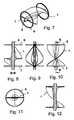
- FIG. 1a three-dimensional, partly broken away view of a rotor of a fluid pump with a support device and an impeller blade;
- FIG. 2an axial plan view of the subject of FIG. 1 ;
- FIG. 3a side view
- FIG. 4a partly broken away side view of the subject of FIG. 1 ;
- FIGS. 5 & 6respective longitudinal sections of the subject of FIG. 1 ;
- FIG. 7a rotor with a support device comprising two rings and an impeller blade in a three-dimensional view
- FIG. 8the subject of FIG. 7 in a longitudinal section
- FIG. 9the subject of FIG. 7 in a first side view
- FIG. 10the subject of FIG. 7 in a second side view
- FIG. 11the subject of FIG. 7 in an axial plan view
- FIG. 12the subject of FIG. 7 in a longitudinal section offset angle-wise with respect to the longitudinal section of FIG. 8 ;
- FIG. 13a rotor with a support device comprising three rings
- FIG. 14a side view of the rotor of FIG. 13 ;
- FIG. 15a rotor with a support device having four rings in a three-dimensional view
- FIG. 16a rotor in which the support device comprises at least one tube piece
- FIG. 17a longitudinal section of the subject matter of FIG. 16 ;
- FIG. 18a rotor in which the impeller blade/impeller blades are surrounded in full by a tubular support device, with reinforcement rings reinforcing the tube;
- FIG. 19the rotor of FIG. 18 in a longitudinal section
- FIG. 20the subject of FIG. 18 in a side view
- FIG. 21the rotor of FIG. 18 in a three-dimensional view, with the support rings being designed in meandering form in the peripheral direction;
- FIG. 22a rotor with a tubular support device which is reinforced by a wire meshwork, in a three-dimensional view
- FIG. 23a rotor similar to that of FIG. 22 , with two rotor blades being arranged without a neck such that they do not extend up to the axis of rotation and can slide past one another on a compression of the rotor;
- FIG. 24the arrangement of FIG. 23 in a longitudinal section
- FIG. 25a rotor arrangement with an impeller blade which is surrounded by a tubular support device, with the support device being connected at both sides to a respective shaft journal by means of fork-like braces;
- FIG. 26a side view of the subject of FIG. 25 ;
- FIG. 27a partly broken away view of the subject of FIG. 26 ;
- FIG. 28a three-dimensional outer view of the subject of FIGS. 25-27 ;
- FIG. 29a partly broken away three-dimensional view of the subject of FIG. 28 .
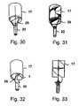
- FIG. 30a rotor with a tubular support device shaft journal, with a single impeller blade being provided;
- FIG. 31the arrangement of FIG. 30 in a partly broken away view
- FIG. 32an embodiment similar to the design of FIG. 30 , with the impeller blade being coupled directly to the shaft journal and not via the support device;
- FIG. 33the design of FIG. 32 in a longitudinal section.
- FIG. 1shows, in a three-dimensional view, a rotor of a fluid pump, in particular of a micropump, for the axial conveying of blood, such as is typically used in medicine to assist the human heart.
- a fluid pumpin particular of a micropump
- Such a pumpis, for example, mounted at the end of a hollow catheter and conducts blood under pressure from a chamber of the heart into a blood vessel when it is introduced into a heart ventricle through a blood vessel.
- a rotorrotates at some thousand revolutions per minute to achieve the required conveying capacity.
- the impeller blade 1is helical in form, is connected to a neck 2 in the region of the axis of rotation 3 and is supported outwardly by a support device 4 in the form of a tubular sleeve, to which the impeller blade 1 is connected at its outer margin.
- the neck 2is typically connected to a drivable shaft which extends through the hollow catheter and blood vessel to a motor drive which can typically be arranged outside the body.
- a sluiceis provided between the motor drive and the hollow catheter.
- FIG. 2shows a plan view in which the upper margin of the impeller blade 1 and the tubular sleeve 4 can easily be recognized.
- the impeller blade 1can also be understood as two partial impeller blades which extend respectively radially from the neck 2 to the tubular support device 4 and axially extend helically.
- FIG. 3shows the rotor from FIG. 1 in a side view, with the closed pipe-like or tubular sleeve 4 being easy to recognize and the ends of the neck 2 projecting beyond it.
- FIG. 4shows a broken away representation of the rotor of FIG. 3 , with the marginal regions of the impeller blade 1 being shown in dashed form where it is connected to the sleeve/support device 4 .
- FIG. 5shows a longitudinal section through the rotor of FIG. 1 , with the impeller blade 1 intersecting the plane of the drawing at the upper end of the rotor.
- the impeller bladecan, as shown in FIG. 5 and also in the following FIG. 6 , be manufactured in one piece with the support device 4 made as a collapsible tube or as a collapsible pipe.
- Said support devicecan, for example, comprise a plastic as a flexible hose and can be held in an expanded and shape-stable manner by the pump action as a result of the overpressure built up in its interior.
- the shape stabilitycan, however, also be established by the elastic restoring forces of the material.
- the impeller bladesare expanded and brought into the shape ready for operation by the expansion movement.
- the impeller blade 1for example, is strained by tension and thus properly stabilized between the support device 4 and the neck 2 in the expanded state.
- FIG. 7An embodiment can be seen from FIG. 7 with two rings 6 , 7 which together form the support device and support the impeller blade 1 .
- the support regions of the impeller blade 1in this respect lie radially of its furthermost margin.
- the rings 6 , 7can comprise a shape memory alloy, nitinol, for example, and can be directly expanded after introduction into a body to adopt the shown circular shape. At the same time, they pull the support regions of the impeller blade 1 radially outwardly and tension it.
- FIG. 8shows a longitudinal section through the rotor in accordance with FIG. 7 and FIG. 9 shows the extent of the margin of the impeller blade in a side view.
- FIG. 10shows a three-dimensional side view which illustrates the helical structure of the impeller blade 1 .
- spacerscan be provided between the rings 6 , 7 which do not have to be shape-changeable and which can maintain their form on the transition between the compressed shape and the expanded shape of the rotor. They can be made as bars or braces extending parallel to the neck 2 .
- the rings 6 , 7can generally also comprise an elastic material, for example rubber-like material, which has small restoring forces on the transport to the point of use in compressed form and which stabilizes itself after adopting the circular ring shape.
- an elastic materialfor example rubber-like material, which has small restoring forces on the transport to the point of use in compressed form and which stabilizes itself after adopting the circular ring shape.
- FIG. 11shows an axial plan view of the rotor in accordance with FIG. 7 and FIG. 12 shows a section in which the impeller blade 1 intersects the plane of the drawing at the upper and lower ends of the rotor.
- the impeller bladepasses through 180 degrees of a helix between the upper end and the lower end of the rotor.
- FIG. 13A rotor of a fluid pump is shown in FIG. 13 which has a support device with three rings 6 , 7 , 8 which are each, viewed radially in the marginal region of the impeller blade 1 , connected to it and can be spaced apart from one another by means of braces, not shown.
- FIG. 14shows a side view of the rotor of FIG. 13 .
- FIG. 15a rotor having four rings 6 , 7 , 8 , 9 is shown perspectively, said rings together forming the major part of a support device.
- the rings 6 , 7 , 8 , 9are shown perspectively, said rings together forming the major part of a support device.
- a helical body 7 acan also be provided circumferentially at the periphery which is shown in dashed form in FIG. 15 and which is fastened spot-wise to the periphery of the impeller blade.
- the torquecan generally be introduced into the rotor via the support device.
- a part of the support devicemust, for example, be connected to a drive device or to a drive shaft via braces. This coupling will be looked at in more detail further below.
- the torquecan also be introduced via the neck 2 provided such a neck is present.
- the effect of the support deviceis restricted to the radial support and shape of the impeller blade/impeller blades.
- FIG. 16shows an embodiment in a three-dimensional representation in which an impeller blade 1 is stabilized at its periphery by a pipe section 10 or a tubular section.
- FIG. 17shows the same arrangement in a longitudinal section.
- the pipe section 10can comprise a plastic, for example, and can be made in one piece with the impeller blade, but can also comprise a material different from the material of the impeller blade, for example a shape memory alloy.
- a tubular section or pipe section of this typehas the disadvantage with respect to a ring of possibly being more difficult to compress, but has the advantage of being easy to stabilize in the expanded shape.
- FIG. 18shows, in a three-dimensional view, a rotor of a fluid pump having a rotor blade 1 which is supported by a support device 11 in the form of a throughgoing tube element.
- the tube element 11extends across the complete axial length of the impeller blade.
- the tube elementcan, however, also be axially shorter than the impeller blade 1 .
- FIG. 19shows a longitudinal section through the embodiment of FIG. 18 , with in particular three ring-like reinforcement elements 12 , 13 , 14 being able to be recognized which are fastened radially outwardly to the tube element 11 or are manufactured in piece therewith in a contiguous manner.
- the reinforcement elements 12 , 13 , 14can comprise the same material as the tube element 11 , but can also comprise another material tending to be stiffer, for example a shape memory alloy of a rubber which may tend to be stiffer than the flexible material which the tube element 11 comprises.
- the tube element 11can be at least partly co-expanded on the unfolding by expansion of the ring-shaped reinforcement elements 12 , 13 , 14 .
- This expansion movementcan moreover be reinforced by an overpressure built up in the rotor as soon as the rotor is set into rotation.
- FIG. 20shows a side view of the rotor of FIGS. 18 , 19 in a closed form.
- FIG. 21A variant is shown in FIG. 21 in which the ring-shaped reinforcement elements 12 ′, 13 ′, 14 ′ are made in meandering form in the peripheral direction.
- These reinforcement elementscan comprise a shape memory material and are particularly easily collapsible by the meander-like design.
- these reinforcement elementscan also have a saw-tooth structure or a wavy-line structure.
- Such reinforcement elementscan be adhered to the tube element, for example.
- FIG. 22shows, in a three-dimensional representation, a tube element 15 which forms a support device for the vane wheel 1 and is reinforced by wire meshwork 16 on its outer side.
- the wire meshwork 16can be adhered, in particular also only spot-wise, to the tube element 15 , for example.
- the wire meshworkcan, as usual with stents, be made so that a radial compression does not result in a change in the length of the wire meshwork.
- the wire meshworkcan comprise a shape memory alloy as a metal wire or also as a grid structure, in particular in one piece; however, a manufacture from a plastic is also conceivable.
- FIG. 23shows an embodiment of a rotor having two impeller blades 1 ′, 1 ′′ which are each helically fastened, for example adhesively bonded, at their outer sides in a tubular element 15 , with the two helical shapes being matched to one another such that the two impeller blades 1 ′, 1 ′′ being able to slide past one another radially with respect to the axis of rotation on compression of the support device 15 so that an extensive compression of the rotor is possible overall.
- Both impeller blades 1 ′, 1 ′′end radially spaced apart from the axis of rotation, with a neck not being present. Only small forces act on the impeller blades at the margin of the rotor blades close to the axis of rotation due by the fluid to be conveyed since the relative movement is small in this region close to the axis.
- the space saved by omitting the neckcan additionally be utilized for the transport of the fluid and the lack of the neck and the ability to push the impeller blades together makes an extensive compression of the rotor possible in the radial direction.
- FIG. 24shows the arrangement of FIG. 23 in a longitudinal section.
- the tubular sleeve which forms the support device for the impeller bladescomprises an inner flexible sleeve and an outer wire meshwork.
- FIGS. 25-29in particular show the coupling of the support device to two shaft journals which are provided at both sides of the rotor and can serve both as a journaling and the introduction of a torque.
- FIG. 25shows, in a longitudinal sectional representation, a tubular support device 17 which is connected via braces 18 , 19 , 20 , 21 to two shaft journals 22 , 23 . Since the impeller blade 1 is supported by the support device 17 , the total rotor is rotatably journalled and driven via the shaft journals 22 , 23 .
- FIG. 26shows a representation rotated by 90° about the axis of rotation 24 in a side view.
- FIG. 27shows a view from the same direction as FIG. 26 in a sectional representation.
- FIGS. 28 , 29show respective three-dimensional representations of the subject of FIGS. 25 , 26 , 27 , with FIG. 28 showing an outer view while FIG. 29 shows a partially broken away representation in which the impeller blade 1 becomes visible within the support device 17 .
- FIGS. 28 , 39unlike FIGS. 25 , 26 , 27 , do not show fork-like braces 18 , 19 as the connection between the support device 17 and the shaft journals 22 , 23 , but rather a triangular plate 25 . It has the advantage with respect to two fork-like braces of being more stable, but the disadvantage that the fluid has to be displaced through the plate 25 on a rotational movement at high rotational frequency.
- FIG. 30shows a support device in which the torque is transmitted from the tubular element 17 into the shaft journal 22 by means of a triangular plate 25 .
- FIG. 31shows the same constellation in a partly broken away representation.
- FIG. 32shows the connection of the shaft journal 22 directly to a prolongation 26 of the impeller blade 1 .
- FIG. 33shows the same constellation as FIG. 32 in a longitudinal section.
- FIGS. 32 and 33make clear that the torque is introduced directly into the impeller blade 1 there and that the support device 17 only serves the stabilization of the impeller blade/impeller blades radially in the outer region or the expansion of the impeller blade and the subsequent shape stabilization.
- the prolongation of the helical structure 26 up to the shaft journal 22moreover has the advantage that this also causes less resistance in the surrounding fluid on rotation since it represents a prolongation of the helical structure of the impeller blade.
Landscapes
- Engineering & Computer Science (AREA)
- Health & Medical Sciences (AREA)
- Heart & Thoracic Surgery (AREA)
- Mechanical Engineering (AREA)
- Life Sciences & Earth Sciences (AREA)
- Anesthesiology (AREA)
- Biomedical Technology (AREA)
- Hematology (AREA)
- Animal Behavior & Ethology (AREA)
- General Health & Medical Sciences (AREA)
- Public Health (AREA)
- Veterinary Medicine (AREA)
- Cardiology (AREA)
- General Engineering & Computer Science (AREA)
- Vascular Medicine (AREA)
- Structures Of Non-Positive Displacement Pumps (AREA)
- External Artificial Organs (AREA)
Abstract
Description
The invention is in the field of mechanical engineering, in particular micromechanics, and addresses fluid pumps which work with rotating impeller blades and are particularly configured for use in areas which are difficult to access.
Pumps of this type can be used, for example, in the medical field and can also have particularly small construction shapes for this purpose.
A special application of micropumps is, for example, the assistance for the pump force of the human heart. Pumps used in this area are usually introduced into the body through blood vessels and are optionally operated in a chamber of the heart.
A plurality of such pumps have already become known which have different constructional shapes. An axial flow pump has become known, from WO 98/53864, and equally fromEP 1 738 783 A1, which in each case has a rotor in the form of a rigid shaft, said rotor being provided with impeller blades and said shaft being outwardly journalled in a stator. The drive can be directly integrated into the stator and the rotor as an electromagnetic drive.
Pumps of this type have the disadvantage that they have a large diameter in relation to the pumping capacity and can hardly be introduced through a blood vessel.
In contrast to this, a rotor is known from WO 03/013745 A2 which has a smaller diameter in a compressed state than in an expanded state and which has an expandable rotor blade which expands in operation by the fluid counterpressure of the blood.
Other rotors which have become known likewise have impeller blades which are expandable for operation, for example by joints or by elastic deformability of the impeller blades.
A particular problem in this respect is that the impeller blades are usually fastened to a central neck and are rotationally drivable and also movably pivotable from this; that the impeller blades thus have to be flexible, but have a certain stiffness or a restriction in its movability, on the other hand, to exert the required pressure onto the fluid for conveying.
This object has previously not been ideally achieved in the prior art. It is therefore the underlying object of the present invention to further develop a pump of the described type to achieve a good pumping capacity in operation despite a small pump diameter in the compressed state. The design should in this respect be as uncomplicated and as inexpensive as possible.
In this respect, at least one impeller blade is provided which is rotatable about an axis of rotation to convey the fluid as well as support device which supports the at least one impeller blade in a support region. The support device is moreover changeable between a compressed rotor state and an expanded rotor state and at least one part of at least one impeller blade extends at least partly, viewed from the support region, radially inwardly toward the rotor axis in the expanded rotor state. Since the support region is not disposed at the radially inner end of the impeller blade, but is rather offset to the impeller blade exterior, viewed radially, the impeller blade/impeller blades is/are supported in a region in which the relative speed to the fluid is greater than in the region of the axis of rotation and, where applicable, the mechanical load of the impeller blade is correspondingly higher. The support region and the support device can be the only region in which the impeller blade/impeller blades is/are journalled or is/are connected to another component. The impeller blade/impeller blades can, for example, be connected to other components in a force-transmitting manner only by means of the support device. In this respect, the region of the impeller blade/impeller blades conveying the fluid can lie wholly or only partly radially within the support region. A lower mechanical demand is in any case made here on the support device and on its connection to the respective impeller blade than if the support device were to support the impeller blades in the region of the axis of rotation. The impeller blades can moreover be made weaker since they are supported in a region of higher load and the mean spacing of the regions of the impeller blade/impeller blades conveying the fluid, viewed in the radial direction, is smaller than if it/they were supported in the region of a neck on the axis of rotation.
The support device can have a strand-like body which extends transversely to the impeller blade surface with respect to its longitudinal direction and/or, in the region in which it supports the impeller blade, passes through said impeller blade or a tangential surface of said impeller blade. The angle between the longitudinal direction of the strand-like body and of the surface normal of the impeller blade surface/of the tangential surface at the impeller blade surface should be less than 89°, preferably less than 85°.
Provision can also be made that the predominant part of the region of the impeller blade/impeller blades conveying the fluid extends radially within the support region/support regions. The support region is thus closer to the parts of the impeller blade/impeller blades which move the fastest and can support them efficiently, for example transmit a torque to them.
Provision can advantageously also be made that the support region is arranged radially outwardly at the periphery of the fluid-conducting region of the impeller blade/impeller blades. In this respect, the support region can completely radially outwardly surround the impeller blades.
The impeller blade can generally be fixedly connected to the support device so that it rotates with the impeller blade.
This is a construction shape which can be manufactured particularly simply and which is mechanically stable. The support device can, for example, comprise the same material as the impeller blade and can be manufactured in one piece therewith.
Provision can, however, also be made that the support device is manufactured from a material different from that of the impeller blade, for example from a superelastic compound or from a shape memory material, in particular nitinol, so that the support device can actively change into an operating shape in order thus to erect the rotor with the impeller blades so that no further demands are made on the impeller blades with respect to an automatic deformation. They can then be manufactured as thin, pliable films which are not self-supporting.
The at least one impeller blade can, however, also be guided and journalled movably with respect to the support device. The support device can then be stationary with respect to the impeller blades as a stator. A guidance, for example in the form of a mechanical or magnetic journaling of the impeller blades with respect to the support device is then necessary.
The support device can, for example, be formed by at least one ring positioned concentrically and optionally journaled with respect to the axis of rotation. This ring can have an axial length which is smaller than the axial length of the impeller blades.
Two or more such rings can also respectively be connected, axially spaced apart, to the impeller blade/impeller blades. The rings can be designed in meandering form in the peripheral direction, for example, to be able to implement a corresponding deformability, for example as a consequence of superelasticity or shape memory properties in a particularly simple manner. A plurality of rings are preferably arranged coaxially to one another.
A helical body can also be provided coaxial to the axis of rotation as a support body instead of one or more rings. It can, for example, have a round or flat cross-section. The helix can extend in the same direction or in the opposite direction to a helical outer margin of an impeller blade.
The support device can, however, also be formed by a flexible tube surrounding the impeller blade/impeller blades. Such a tube can itself comprise a shape memory material, for example, also a wire meshwork of nitinol wire or it can comprise a flexible organic material impermeable for the fluid and have support elements such as support rings, for example. The tube can be inflatable in pumping operation by overpressure as a result of the fluid pressure which has built up.
The tube can be connected at points or in parts to the outer ends of the impeller blade/impeller blades.
In accordance with the present invention, the rotor does not need a neck in the region of the impeller blades so that the impeller blade/impeller blades, with all its/their parts, can be spaced apart from the axis of rotation. In this case, the cross-section of the rotor, which is otherwise taken up by a neck, is additionally available for conveying fluid.
When the support device rotates with the impeller blade/impeller blades, it can be journalled in at least one rotary bearing which is axially arranged outside the region over which the impeller blade/impeller blades extends/extend.
This design allows a simple journaling in a commercial rotary bearing, for example a roller bearing or a magnetic bearing. Such a journaling is less complicated and lower in friction than a journaling at the periphery of the support device in the region of the impeller blades.
However, a hydrodynamic journaling can, for example, also be provided at the periphery of the support device when a rotor of the described kind runs in a housing and when a gap is provided between the housing and the support device in which a fluid is located. In a particularly simple embodiment, this fluid could be identical with the conveyed fluid.
The invention will be shown and subsequently described in the following with reference to an embodiment in a drawing. There are shown
Theneck 2 is typically connected to a drivable shaft which extends through the hollow catheter and blood vessel to a motor drive which can typically be arranged outside the body. A sluice is provided between the motor drive and the hollow catheter.FIG. 2 shows a plan view in which the upper margin of theimpeller blade 1 and thetubular sleeve 4 can easily be recognized.
Theimpeller blade 1 can also be understood as two partial impeller blades which extend respectively radially from theneck 2 to thetubular support device 4 and axially extend helically.
The impeller blade can, as shown inFIG. 5 and also in the followingFIG. 6 , be manufactured in one piece with thesupport device 4 made as a collapsible tube or as a collapsible pipe. Said support device can, for example, comprise a plastic as a flexible hose and can be held in an expanded and shape-stable manner by the pump action as a result of the overpressure built up in its interior. The shape stability can, however, also be established by the elastic restoring forces of the material. At the same time, the impeller blades are expanded and brought into the shape ready for operation by the expansion movement. Theimpeller blade 1, for example, is strained by tension and thus properly stabilized between thesupport device 4 and theneck 2 in the expanded state.
An embodiment can be seen fromFIG. 7 with tworings impeller blade 1. The support regions of theimpeller blade 1 in this respect lie radially of its furthermost margin.
Therings impeller blade 1 radially outwardly and tension it.
In addition to the elements shown, spacers can be provided between therings neck 2.
Therings
A rotor of a fluid pump is shown inFIG. 13 which has a support device with threerings impeller blade 1, connected to it and can be spaced apart from one another by means of braces, not shown.
InFIG. 15 , a rotor having fourrings rings
Instead of individual rings, a helical body7acan also be provided circumferentially at the periphery which is shown in dashed form inFIG. 15 and which is fastened spot-wise to the periphery of the impeller blade.
The torque can generally be introduced into the rotor via the support device. For this purpose, a part of the support device must, for example, be connected to a drive device or to a drive shaft via braces. This coupling will be looked at in more detail further below.
Alternatively, the torque can also be introduced via theneck 2 provided such a neck is present. In this case, the effect of the support device is restricted to the radial support and shape of the impeller blade/impeller blades.
Thepipe section 10 can comprise a plastic, for example, and can be made in one piece with the impeller blade, but can also comprise a material different from the material of the impeller blade, for example a shape memory alloy. A tubular section or pipe section of this type has the disadvantage with respect to a ring of possibly being more difficult to compress, but has the advantage of being easy to stabilize in the expanded shape.
Thereinforcement elements tube element 11, but can also comprise another material tending to be stiffer, for example a shape memory alloy of a rubber which may tend to be stiffer than the flexible material which thetube element 11 comprises.
In this respect, thetube element 11 can be at least partly co-expanded on the unfolding by expansion of the ring-shapedreinforcement elements
A variant is shown inFIG. 21 in which the ring-shapedreinforcement elements 12′,13′,14′ are made in meandering form in the peripheral direction. These reinforcement elements can comprise a shape memory material and are particularly easily collapsible by the meander-like design. In addition to the rectangular meander-like structure shown, these reinforcement elements can also have a saw-tooth structure or a wavy-line structure.
Such reinforcement elements can be adhered to the tube element, for example.
Bothimpeller blades 1′,1″ end radially spaced apart from the axis of rotation, with a neck not being present. Only small forces act on the impeller blades at the margin of the rotor blades close to the axis of rotation due by the fluid to be conveyed since the relative movement is small in this region close to the axis. The space saved by omitting the neck can additionally be utilized for the transport of the fluid and the lack of the neck and the ability to push the impeller blades together makes an extensive compression of the rotor possible in the radial direction.
In a similar manner to the design ofFIG. 22 , the tubular sleeve which forms the support device for the impeller blades comprises an inner flexible sleeve and an outer wire meshwork.
It becomes visible fromFIG. 29 that a singlehelical impeller blade 1 is provided which has no neck.
In contrast to this,FIG. 32 shows the connection of theshaft journal 22 directly to aprolongation 26 of theimpeller blade 1.
It was made clear by the above-described examples that a high stabilization of the impeller blades is achieved with a small effort with the means of the invention by the support of one or several impeller blades radially in their outer region. The connection of impeller blades to a neck is thereby either not particularly taken up or it becomes unnecessary in total, which can also result in the omission of the neck. The support device can moreover co-expand the rotor blade/rotor blades on the expansion of the rotor so that they can be manufactured from commercial, flexible materials without any particularly high mechanical demands.
Claims (11)
1. A fluid pump comprising: at least one impeller blade which is rotatable about an axis of rotation and conveys a fluid in operation; and comprising a support device which supports the at least one impeller blade in at least one support region, wherein the support device is changeable between a first state in which the at least one impeller blade is radially compressed and a second state in which the at least one impeller blade is radially expanded; and wherein the at least one impeller blade extends at least partly radially inwardly with respect to the axis of rotation from the at least one support region in the radially expanded state of the at least one impeller blade;
wherein the support device is formed by at least one ring concentrically journalled with respect to the axis of rotation,
wherein the at least one ring is designed in meandering form in the peripheral direction.
2. The fluid pump in accordance withclaim 1 , wherein the predominant part of the at least one impeller blade conveying the fluid extends radially within the at least one support region.
3. The fluid pump in accordance withclaim 2 , wherein the support region is arranged radially outwardly at the periphery of the region of the at least one impeller blade conveying the fluid.
4. The fluid pump in accordance withclaim 3 , wherein the at least one impeller blade is connected to the support device and said support device rotates with the at least one impeller blade.
5. The fluid pump in accordance withclaim 1 , wherein the support device is formed by a flexible tube at least partly surrounding the at least one impeller blade.
6. The fluid pump in accordance withclaim 5 , wherein the tube is inflatable and stable in shape in pumping operation due to the overpressure as a result of the pumping operation.
7. The fluid pump in accordance withclaim 1 , wherein the at least one impeller blade is radially spaced apart with all its parts from the axis of rotation.
8. The fluid pump in accordance withclaim 1 , wherein the fluid pump has no neck in the region of the at least one impeller blade.
9. The fluid pump in accordance withclaim 1 , wherein the at least one ring comprises an elastic material.
10. The fluid pump in accordance withclaim 1 , wherein the support device has a wire meshwork compressible in diameter.
11. The fluid pump in accordance withclaim 1 , wherein the support device is journalled in at least one rotary bearing which is arranged axially outside the region in which the at least one impeller blade extends.
Priority Applications (1)
| Application Number | Priority Date | Filing Date | Title |
|---|---|---|---|
| US13/261,205US9089634B2 (en) | 2009-09-22 | 2010-09-22 | Fluid pump having at least one impeller blade and a support device |
Applications Claiming Priority (5)
| Application Number | Priority Date | Filing Date | Title |
|---|---|---|---|
| US24459209P | 2009-09-22 | 2009-09-22 | |
| EP09075441AEP2298373A1 (en) | 2009-09-22 | 2009-09-22 | Fluid pump with at least one turbine blade and a seating device |
| EP09075441.7 | 2009-09-22 | ||
| US13/261,205US9089634B2 (en) | 2009-09-22 | 2010-09-22 | Fluid pump having at least one impeller blade and a support device |
| PCT/EP2010/005867WO2011035927A1 (en) | 2009-09-22 | 2010-09-22 | Fluid pump having at least one impeller blade and a support device |
Related Parent Applications (1)
| Application Number | Title | Priority Date | Filing Date |
|---|---|---|---|
| PCT/EP2010/005867A-371-Of-InternationalWO2011035927A1 (en) | 2009-09-22 | 2010-09-22 | Fluid pump having at least one impeller blade and a support device |
Related Child Applications (1)
| Application Number | Title | Priority Date | Filing Date |
|---|---|---|---|
| US14/807,615ContinuationUS10208763B2 (en) | 2009-09-22 | 2015-07-23 | Fluid pump having at least one impeller blade and a support device |
Publications (2)
| Publication Number | Publication Date |
|---|---|
| US20120224970A1 US20120224970A1 (en) | 2012-09-06 |
| US9089634B2true US9089634B2 (en) | 2015-07-28 |
Family
ID=41667412
Family Applications (5)
| Application Number | Title | Priority Date | Filing Date |
|---|---|---|---|
| US13/261,205Active2032-03-12US9089634B2 (en) | 2009-09-22 | 2010-09-22 | Fluid pump having at least one impeller blade and a support device |
| US14/807,615Active2032-07-23US10208763B2 (en) | 2009-09-22 | 2015-07-23 | Fluid pump having at least one impeller blade and a support device |
| US16/243,855Active2033-09-13US11592028B2 (en) | 2009-09-22 | 2019-01-09 | Fluid pump having at least one impeller blade and a support device |
| US18/098,761ActiveUS12066030B2 (en) | 2009-09-22 | 2023-01-19 | Fluid pump having at least one impeller blade and a support device |
| US18/773,050PendingUS20250012290A1 (en) | 2009-09-22 | 2024-07-15 | Fluid pump having at least one impeller blade and a support device |
Family Applications After (4)
| Application Number | Title | Priority Date | Filing Date |
|---|---|---|---|
| US14/807,615Active2032-07-23US10208763B2 (en) | 2009-09-22 | 2015-07-23 | Fluid pump having at least one impeller blade and a support device |
| US16/243,855Active2033-09-13US11592028B2 (en) | 2009-09-22 | 2019-01-09 | Fluid pump having at least one impeller blade and a support device |
| US18/098,761ActiveUS12066030B2 (en) | 2009-09-22 | 2023-01-19 | Fluid pump having at least one impeller blade and a support device |
| US18/773,050PendingUS20250012290A1 (en) | 2009-09-22 | 2024-07-15 | Fluid pump having at least one impeller blade and a support device |
Country Status (5)
| Country | Link |
|---|---|
| US (5) | US9089634B2 (en) |
| EP (1) | EP2298373A1 (en) |
| CN (1) | CN102655891B (en) |
| DE (1) | DE112010003745T5 (en) |
| WO (1) | WO2011035927A1 (en) |
Cited By (50)
| Publication number | Priority date | Publication date | Assignee | Title |
|---|---|---|---|---|
| US20160053768A1 (en)* | 2009-09-22 | 2016-02-25 | Ecp Entwicklungsgesellschaft Mbh | Fluid pump having at least one impeller blade and a support device |
| USD767112S1 (en)* | 2015-04-15 | 2016-09-20 | K&N Engineering, Inc. | Vent breather |
| US9675738B2 (en) | 2015-01-22 | 2017-06-13 | Tc1 Llc | Attachment mechanisms for motor of catheter pump |
| US9675739B2 (en) | 2015-01-22 | 2017-06-13 | Tc1 Llc | Motor assembly with heat exchanger for catheter pump |
| US9675740B2 (en) | 2012-05-14 | 2017-06-13 | Tc1 Llc | Impeller for catheter pump |
| US9717833B2 (en) | 2004-09-17 | 2017-08-01 | The Penn State Research Foundation | Heart assist device with expandable impeller pump |
| US9770543B2 (en) | 2015-01-22 | 2017-09-26 | Tc1 Llc | Reduced rotational mass motor assembly for catheter pump |
| US9827356B2 (en) | 2014-04-15 | 2017-11-28 | Tc1 Llc | Catheter pump with access ports |
| US9872947B2 (en) | 2012-05-14 | 2018-01-23 | Tc1 Llc | Sheath system for catheter pump |
| US9962475B2 (en) | 2011-01-06 | 2018-05-08 | Tc1 Llc | Percutaneous heart pump |
| US20180140759A1 (en)* | 2016-11-21 | 2018-05-24 | Cardiobridge Gmbh | Catheter pump with a pump head for insertion into the aorta |
| US10071192B2 (en) | 2013-03-15 | 2018-09-11 | Tc1 Llp | Catheter pump assembly including a stator |
| US10086121B2 (en) | 2012-07-03 | 2018-10-02 | Tc1 Llc | Catheter pump |
| US10105475B2 (en) | 2014-04-15 | 2018-10-23 | Tc1 Llc | Catheter pump introducer systems and methods |
| US10117980B2 (en) | 2012-05-14 | 2018-11-06 | Tc1 Llc | Distal bearing support |
| US10215187B2 (en) | 2004-09-17 | 2019-02-26 | Tc1 Llc | Expandable impeller pump |
| US10525178B2 (en) | 2013-03-15 | 2020-01-07 | Tc1 Llc | Catheter pump assembly including a stator |
| US10576193B2 (en) | 2012-07-03 | 2020-03-03 | Tc1 Llc | Motor assembly for catheter pump |
| US10583232B2 (en) | 2014-04-15 | 2020-03-10 | Tc1 Llc | Catheter pump with off-set motor position |
| US10632241B2 (en) | 2013-03-13 | 2020-04-28 | Tc1 Llc | Fluid handling system |
| US10668195B2 (en) | 2018-06-01 | 2020-06-02 | Fbr Medical, Inc. | Catheter pump with fixed-diameter impeller |
| US10722631B2 (en) | 2018-02-01 | 2020-07-28 | Shifamed Holdings, Llc | Intravascular blood pumps and methods of use and manufacture |
| US11077294B2 (en) | 2013-03-13 | 2021-08-03 | Tc1 Llc | Sheath assembly for catheter pump |
| US11185677B2 (en) | 2017-06-07 | 2021-11-30 | Shifamed Holdings, Llc | Intravascular fluid movement devices, systems, and methods of use |
| US11219756B2 (en) | 2012-07-03 | 2022-01-11 | Tc1 Llc | Motor assembly for catheter pump |
| US11229786B2 (en) | 2012-05-14 | 2022-01-25 | Tc1 Llc | Impeller for catheter pump |
| US11376416B2 (en)* | 2008-10-10 | 2022-07-05 | Peter Forsell | Heart help pump, system, and method |
| US11511103B2 (en) | 2017-11-13 | 2022-11-29 | Shifamed Holdings, Llc | Intravascular fluid movement devices, systems, and methods of use |
| US11648392B2 (en) | 2016-11-23 | 2023-05-16 | Magenta Medical Ltd. | Blood pumps |
| US11648391B2 (en) | 2013-03-13 | 2023-05-16 | Magenta Medical Ltd. | Blood pump |
| US11648387B2 (en) | 2015-05-18 | 2023-05-16 | Magenta Medical Ltd. | Blood pump |
| US11654275B2 (en) | 2019-07-22 | 2023-05-23 | Shifamed Holdings, Llc | Intravascular blood pumps with struts and methods of use and manufacture |
| US11666747B2 (en) | 2019-01-24 | 2023-06-06 | Magenta Medical Ltd. | Manufacturing an impeller |
| US11684275B2 (en) | 2018-01-10 | 2023-06-27 | Magenta Medical Ltd. | Distal tip element for blood pump |
| US11724089B2 (en) | 2019-09-25 | 2023-08-15 | Shifamed Holdings, Llc | Intravascular blood pump systems and methods of use and control thereof |
| US11839540B2 (en) | 2012-06-06 | 2023-12-12 | Magenta Medical Ltd | Vena-caval apparatus and methods |
| US11839754B2 (en) | 2016-10-25 | 2023-12-12 | Magenta Medical Ltd | Ventricular assist device |
| US11850414B2 (en) | 2013-03-13 | 2023-12-26 | Tc1 Llc | Fluid handling system |
| US11883274B2 (en) | 2013-03-13 | 2024-01-30 | Magenta Medical Ltd. | Vena-caval blood pump |
| US11964145B2 (en) | 2019-07-12 | 2024-04-23 | Shifamed Holdings, Llc | Intravascular blood pumps and methods of manufacture and use |
| US12102815B2 (en) | 2019-09-25 | 2024-10-01 | Shifamed Holdings, Llc | Catheter blood pumps and collapsible pump housings |
| US12121713B2 (en) | 2019-09-25 | 2024-10-22 | Shifamed Holdings, Llc | Catheter blood pumps and collapsible blood conduits |
| US12128227B2 (en) | 2020-04-07 | 2024-10-29 | Magenta Medical Ltd. | Manufacture of an impeller |
| US12128228B2 (en) | 2019-05-23 | 2024-10-29 | Magenta Medical Ltd | Blood pumps |
| US12161857B2 (en) | 2018-07-31 | 2024-12-10 | Shifamed Holdings, Llc | Intravascular blood pumps and methods of use |
| US12220570B2 (en) | 2018-10-05 | 2025-02-11 | Shifamed Holdings, Llc | Intravascular blood pumps and methods of use |
| US12343518B2 (en) | 2018-01-10 | 2025-07-01 | Magenta Medical Ltd. | Blood-pressure-measurement element |
| US12350483B2 (en) | 2016-07-21 | 2025-07-08 | Tc1 Llc | Fluid seals for catheter pump motor assembly |
| US12409310B2 (en) | 2019-12-11 | 2025-09-09 | Shifamed Holdings, Llc | Descending aorta and vena cava blood pumps |
| US12440665B2 (en) | 2021-11-22 | 2025-10-14 | Magenta Medical Ltd. | Magnetic phase detection |
Families Citing this family (61)
| Publication number | Priority date | Publication date | Assignee | Title |
|---|---|---|---|---|
| EP2194278A1 (en) | 2008-12-05 | 2010-06-09 | ECP Entwicklungsgesellschaft mbH | Fluid pump with a rotor |
| EP2216059A1 (en) | 2009-02-04 | 2010-08-11 | ECP Entwicklungsgesellschaft mbH | Catheter device with a catheter and an actuation device |
| EP2229965A1 (en) | 2009-03-18 | 2010-09-22 | ECP Entwicklungsgesellschaft mbH | Fluid pump with particular form of a rotor blade |
| EP2246078A1 (en) | 2009-04-29 | 2010-11-03 | ECP Entwicklungsgesellschaft mbH | Shaft assembly with a shaft which moves within a fluid-filled casing |
| EP2248544A1 (en) | 2009-05-05 | 2010-11-10 | ECP Entwicklungsgesellschaft mbH | Fluid pump with variable circumference, particularly for medical use |
| EP2266640A1 (en) | 2009-06-25 | 2010-12-29 | ECP Entwicklungsgesellschaft mbH | Compressible and expandable turbine blade for a fluid pump |
| EP2282070B1 (en) | 2009-08-06 | 2012-10-17 | ECP Entwicklungsgesellschaft mbH | Catheter device with a coupling device for a drive device |
| EP2298371A1 (en) | 2009-09-22 | 2011-03-23 | ECP Entwicklungsgesellschaft mbH | Function element, in particular fluid pump with a housing and a transport element |
| EP2298372A1 (en) | 2009-09-22 | 2011-03-23 | ECP Entwicklungsgesellschaft mbH | Rotor for an axial pump for transporting a fluid |
| EP2299119B1 (en) | 2009-09-22 | 2018-11-07 | ECP Entwicklungsgesellschaft mbH | Inflatable rotor for a fluid pump |
| EP2314330A1 (en) | 2009-10-23 | 2011-04-27 | ECP Entwicklungsgesellschaft mbH | Flexible shaft arrangement |
| EP2314331B1 (en) | 2009-10-23 | 2013-12-11 | ECP Entwicklungsgesellschaft mbH | Catheter pump arrangement and flexible shaft arrangement with a cable core |
| EP2338541A1 (en) | 2009-12-23 | 2011-06-29 | ECP Entwicklungsgesellschaft mbH | Radial compressible and expandable rotor for a fluid pump |
| EP2338540A1 (en) | 2009-12-23 | 2011-06-29 | ECP Entwicklungsgesellschaft mbH | Delivery blade for a compressible rotor |
| EP2338539A1 (en) | 2009-12-23 | 2011-06-29 | ECP Entwicklungsgesellschaft mbH | Pump device with a detection device |
| EP2347778A1 (en) | 2010-01-25 | 2011-07-27 | ECP Entwicklungsgesellschaft mbH | Fluid pump with a radially compressible rotor |
| EP2363157A1 (en) | 2010-03-05 | 2011-09-07 | ECP Entwicklungsgesellschaft mbH | Device for exerting mechanical force on a medium, in particular fluid pump |
| EP2388029A1 (en) | 2010-05-17 | 2011-11-23 | ECP Entwicklungsgesellschaft mbH | Pump array |
| EP2399639A1 (en) | 2010-06-25 | 2011-12-28 | ECP Entwicklungsgesellschaft mbH | System for introducing a pump |
| EP2407186A1 (en) | 2010-07-15 | 2012-01-18 | ECP Entwicklungsgesellschaft mbH | Rotor for a pump, produced with an initial elastic material |
| EP2407187A3 (en) | 2010-07-15 | 2012-06-20 | ECP Entwicklungsgesellschaft mbH | Blood pump for invasive application within the body of a patient |
| EP2407185A1 (en) | 2010-07-15 | 2012-01-18 | ECP Entwicklungsgesellschaft mbH | Radial compressible and expandable rotor for a pump with a turbine blade |
| EP2422735A1 (en) | 2010-08-27 | 2012-02-29 | ECP Entwicklungsgesellschaft mbH | Implantable blood transportation device, manipulation device and coupling device |
| EP2497521A1 (en) | 2011-03-10 | 2012-09-12 | ECP Entwicklungsgesellschaft mbH | Push device for axial insertion of a string-shaped, flexible body |
| US9162017B2 (en)* | 2011-08-29 | 2015-10-20 | Minnetronix, Inc. | Expandable vascular pump |
| EP2564771A1 (en) | 2011-09-05 | 2013-03-06 | ECP Entwicklungsgesellschaft mbH | Medicinal product with a functional element for invasive use in the body of a patient |
| US8926492B2 (en) | 2011-10-11 | 2015-01-06 | Ecp Entwicklungsgesellschaft Mbh | Housing for a functional element |
| US9327067B2 (en) | 2012-05-14 | 2016-05-03 | Thoratec Corporation | Impeller for catheter pump |
| US20140100310A1 (en) | 2012-10-08 | 2014-04-10 | Teknor Apex Company | Thermoplastic elastomer compositions having biorenewable content |
| US9764113B2 (en) | 2013-12-11 | 2017-09-19 | Magenta Medical Ltd | Curved catheter |
| WO2015160943A1 (en) | 2014-04-15 | 2015-10-22 | Thoratec Corporation | Sensors for catheter pumps |
| EP3583973A1 (en) | 2014-08-18 | 2019-12-25 | Tc1 Llc | Guide features for percutaneous catheter pump |
| US9907890B2 (en) | 2015-04-16 | 2018-03-06 | Tc1 Llc | Catheter pump with positioning brace |
| EP4548956A3 (en)* | 2015-08-04 | 2025-08-06 | Abiomed Europe GmbH | Blood pump with self-flushing bearing |
| EP3808401A1 (en) | 2016-07-21 | 2021-04-21 | Tc1 Llc | Gas-filled chamber for catheter pump motor assembly |
| EP3518825B1 (en) | 2016-09-29 | 2020-05-27 | Magenta Medical Ltd. | Blood vessel tube |
| US20180172020A1 (en)* | 2016-12-15 | 2018-06-21 | Saudi Arabian Oil Company | Wellbore tools including smart materials |
| RU2650457C1 (en)* | 2017-01-18 | 2018-04-13 | ООО "Научно-производственное объединение Челнинский насосный завод" | Impeller and compressor stage guide of the submerged centrifugal pump |
| FR3071282B1 (en) | 2017-09-21 | 2022-04-08 | Fineheart | INTERNAL BLADE TURBINE |
| DE102018201030B4 (en) | 2018-01-24 | 2025-10-16 | Kardion Gmbh | Magnetic dome element with magnetic bearing function |
| US10893927B2 (en) | 2018-03-29 | 2021-01-19 | Magenta Medical Ltd. | Inferior vena cava blood-flow implant |
| DE102018207575A1 (en) | 2018-05-16 | 2019-11-21 | Kardion Gmbh | Magnetic face turning coupling for the transmission of torques |
| DE102018207611A1 (en) | 2018-05-16 | 2019-11-21 | Kardion Gmbh | Rotor bearing system |
| DE102018208550A1 (en) | 2018-05-30 | 2019-12-05 | Kardion Gmbh | A lead device for directing blood flow to a cardiac assist system, cardiac assist system, and method of making a lead device |
| DE102018208538A1 (en) | 2018-05-30 | 2019-12-05 | Kardion Gmbh | Intravascular blood pump and process for the production of electrical conductors |
| DE102018208541A1 (en) | 2018-05-30 | 2019-12-05 | Kardion Gmbh | Axial pump for a cardiac assist system and method of making an axial pump for a cardiac assist system |
| DE102018208539A1 (en) | 2018-05-30 | 2019-12-05 | Kardion Gmbh | A motor housing module for sealing an engine compartment of a motor of a cardiac assist system and cardiac assistance system and method for mounting a cardiac assist system |
| DE102018210076A1 (en) | 2018-06-21 | 2019-12-24 | Kardion Gmbh | Method and device for detecting a state of wear of a cardiac support system, method and device for operating a cardiac support system and cardiac support system |
| DE102018210058A1 (en) | 2018-06-21 | 2019-12-24 | Kardion Gmbh | Stator blade device for guiding the flow of a fluid flowing out of an outlet opening of a heart support system, heart support system with stator blade device, method for operating a stator blade device and manufacturing method |
| DE102018211327A1 (en) | 2018-07-10 | 2020-01-16 | Kardion Gmbh | Impeller for an implantable vascular support system |
| DE102018212153A1 (en) | 2018-07-20 | 2020-01-23 | Kardion Gmbh | Inlet line for a pump unit of a cardiac support system, cardiac support system and method for producing an inlet line for a pump unit of a cardiac support system |
| US11541224B2 (en) | 2018-07-30 | 2023-01-03 | Cardiovascular Systems, Inc. | Intravascular pump without inducer and centrifugal force-driven expansion of impeller blades and/or expandable and collapsible impeller housing |
| CN112654389A (en) | 2018-08-07 | 2021-04-13 | 开迪恩有限公司 | Bearing device for a cardiac support system and method for flushing an intermediate space in a bearing device for a cardiac support system |
| CN111166949A (en)* | 2018-11-13 | 2020-05-19 | 上海微创医疗器械(集团)有限公司 | Impeller, method for manufacturing impeller, and percutaneous blood pump |
| CN113123972B (en) | 2019-12-31 | 2023-06-06 | 丹佛斯(天津)有限公司 | Oil pump and scroll compressor |
| DE102020102474A1 (en) | 2020-01-31 | 2021-08-05 | Kardion Gmbh | Pump for conveying a fluid and method for manufacturing a pump |
| WO2024057257A2 (en)* | 2022-09-14 | 2024-03-21 | Magenta Medical Ltd | Pump-head portion of ventricular assist device |
| CN116317290A (en)* | 2022-09-20 | 2023-06-23 | 安徽通灵仿生科技有限公司 | Catheter pump motor |
| WO2024153205A1 (en)* | 2023-01-18 | 2024-07-25 | 上海魅丽纬叶医疗科技有限公司 | Foldable composite rotating blades and medical power pump |
| CN119327028B (en)* | 2024-10-28 | 2025-08-01 | 同济大学 | Micro pump head |
| CN120384890B (en)* | 2025-06-30 | 2025-09-26 | 成都永益泵业股份有限公司 | Slurry pump impeller and manufacturing method thereof |
Citations (135)
| Publication number | Priority date | Publication date | Assignee | Title |
|---|---|---|---|---|
| US3510229A (en) | 1968-07-23 | 1970-05-05 | Maytag Co | One-way pump |
| US3568659A (en) | 1968-09-24 | 1971-03-09 | James N Karnegis | Disposable percutaneous intracardiac pump and method of pumping blood |
| US3802551A (en)* | 1971-02-17 | 1974-04-09 | S Somers | Flexible tubular conveyor |
| US3812812A (en) | 1973-06-25 | 1974-05-28 | M Hurwitz | Trolling propeller with self adjusting hydrodynamic spoilers |
| US4014317A (en) | 1972-02-18 | 1977-03-29 | The United States Of America As Represented By The Department Of Health, Education And Welfare | Multipurpose cardiocirculatory assist cannula and methods of use thereof |
| US4207028A (en) | 1979-06-12 | 1980-06-10 | Ridder Sven O | Extendable and retractable propeller for watercraft |
| US4559951A (en) | 1982-11-29 | 1985-12-24 | Cardiac Pacemakers, Inc. | Catheter assembly |
| US4563181A (en) | 1983-02-18 | 1986-01-07 | Mallinckrodt, Inc. | Fused flexible tip catheter |
| US4679558A (en) | 1985-08-12 | 1987-07-14 | Intravascular Surgical Instruments, Inc. | Catheter based surgical methods and apparatus therefor |
| US4686982A (en) | 1985-06-19 | 1987-08-18 | John Nash | Spiral wire bearing for rotating wire drive catheter |
| US4747821A (en) | 1986-10-22 | 1988-05-31 | Intravascular Surgical Instruments, Inc. | Catheter with high speed moving working head |
| US4749376A (en) | 1986-10-24 | 1988-06-07 | Intravascular Surgical Instruments, Inc. | Reciprocating working head catheter |
| US4753221A (en) | 1986-10-22 | 1988-06-28 | Intravascular Surgical Instruments, Inc. | Blood pumping catheter and method of use |
| US4801243A (en) | 1985-12-28 | 1989-01-31 | Bird-Johnson Company | Adjustable diameter screw propeller |
| US4817613A (en) | 1987-07-13 | 1989-04-04 | Devices For Vascular Intervention, Inc. | Guiding catheter |
| US4919647A (en) | 1988-10-13 | 1990-04-24 | Kensey Nash Corporation | Aortically located blood pumping catheter and method of use |
| US4957504A (en) | 1988-12-02 | 1990-09-18 | Chardack William M | Implantable blood pump |
| US4969865A (en) | 1989-01-09 | 1990-11-13 | American Biomed, Inc. | Helifoil pump |
| US4995857A (en) | 1989-04-07 | 1991-02-26 | Arnold John R | Left ventricular assist device and method for temporary and permanent procedures |
| US5011469A (en) | 1988-08-29 | 1991-04-30 | Shiley, Inc. | Peripheral cardiopulmonary bypass and coronary reperfusion system |
| GB2239675A (en) | 1989-12-05 | 1991-07-10 | Man Fai Shiu | Pump for pumping liquid |
| US5040944A (en) | 1989-09-11 | 1991-08-20 | Cook Einar P | Pump having impeller rotational about convoluted stationary member |
| US5042984A (en) | 1989-08-17 | 1991-08-27 | Kensey Nash Corporation | Catheter with working head having selectable impacting surfaces and method of using the same |
| US5052404A (en) | 1989-03-02 | 1991-10-01 | The Microspring Company, Inc. | Torque transmitter |
| US5061256A (en) | 1987-12-07 | 1991-10-29 | Johnson & Johnson | Inflow cannula for intravascular blood pumps |
| US5092844A (en) | 1990-04-10 | 1992-03-03 | Mayo Foundation For Medical Education And Research | Intracatheter perfusion pump apparatus and method |
| US5097849A (en) | 1989-08-17 | 1992-03-24 | Kensey Nash Corporation | Method of use of catheter with working head having selectable impacting surfaces |
| US5108411A (en) | 1990-03-28 | 1992-04-28 | Cardiovascular Imaging Systems, Inc. | Flexible catheter drive cable |
| US5112292A (en) | 1989-01-09 | 1992-05-12 | American Biomed, Inc. | Helifoil pump |
| US5113872A (en) | 1990-04-18 | 1992-05-19 | Cordis Corporation | Guidewire extension system with connectors |
| US5117838A (en) | 1990-04-18 | 1992-06-02 | Cordis Corporation | Rotating guidewire extension system |
| US5118264A (en) | 1990-01-11 | 1992-06-02 | The Cleveland Clinic Foundation | Purge flow control in rotary blood pumps |
| US5145333A (en) | 1990-03-01 | 1992-09-08 | The Cleveland Clinic Foundation | Fluid motor driven blood pump |
| US5163910A (en) | 1990-04-10 | 1992-11-17 | Mayo Foundation For Medical Education And Research | Intracatheter perfusion pump apparatus and method |
| US5169378A (en) | 1990-07-20 | 1992-12-08 | Diego Figuera | Intra-ventricular expansible assist pump |
| US5183384A (en) | 1988-05-16 | 1993-02-02 | Trumbly Joe H | Foldable propeller assembly |
| US5191888A (en) | 1990-04-18 | 1993-03-09 | Cordis Corporation | Assembly of an extension guidewire and an alignment tool for same |
| US5192286A (en) | 1991-07-26 | 1993-03-09 | Regents Of The University Of California | Method and device for retrieving materials from body lumens |
| US5201679A (en) | 1991-12-13 | 1993-04-13 | Attwood Corporation | Marine propeller with breakaway hub |
| US5275580A (en) | 1990-03-08 | 1994-01-04 | Kenji Yamazaki | Auxiliary artificial heart of the embedded-in-body type |
| US5300112A (en) | 1992-07-14 | 1994-04-05 | Aai Corporation | Articulated heart pump |
| US5373619A (en) | 1987-09-30 | 1994-12-20 | Lake Region Manufacturing Co., Inc. | Method of making a hollow lumen cable |
| US5376114A (en) | 1992-10-30 | 1994-12-27 | Jarvik; Robert | Cannula pumps for temporary cardiac support and methods of their application and use |
| US5501574A (en) | 1993-06-28 | 1996-03-26 | Baxter International Inc. | Blood pump |
| US5531789A (en) | 1993-12-24 | 1996-07-02 | Sun Medical Technology Research Corporation | Sealing system of an artificial internal organ |
| US5676162A (en) | 1992-08-06 | 1997-10-14 | Electric Boat Corporation | Reciprocating pump and linear motor arrangement |
| US5701911A (en) | 1996-04-05 | 1997-12-30 | Medtronic, Inc. | Guide wire extension docking system |
| US5749855A (en)* | 1992-09-02 | 1998-05-12 | Reitan; Oyvind | Catheter pump |
| US5813405A (en) | 1990-04-18 | 1998-09-29 | Cordis Corporation | Snap-in connection assembly for extension guidewire system |
| US5820571A (en) | 1996-06-24 | 1998-10-13 | C. R. Bard, Inc. | Medical backloading wire |
| WO1998053864A1 (en) | 1997-05-30 | 1998-12-03 | Cardinove Inc. | Ventricular assist device comprising an enclosed-impeller axial flow blood pump |
| US5851174A (en) | 1996-09-17 | 1998-12-22 | Robert Jarvik | Cardiac support device |
| US5882329A (en) | 1997-02-12 | 1999-03-16 | Prolifix Medical, Inc. | Apparatus and method for removing stenotic material from stents |
| US5938672A (en) | 1996-07-26 | 1999-08-17 | Kensey Nash Corporation | System and method of use for revascularizing stenotic bypass grafts and other blood vessels |
| US6030397A (en) | 1998-12-16 | 2000-02-29 | Micro Therapeutics, Inc. | Miniaturized medical brush |
| US6129704A (en) | 1997-06-12 | 2000-10-10 | Schneider (Usa) Inc. | Perfusion balloon catheter having a magnetically driven impeller |
| US6152693A (en) | 1993-12-23 | 2000-11-28 | Gori Marine As | Folding propeller |
| US6168624B1 (en) | 1996-05-21 | 2001-01-02 | Amnon Sudai | Apparatus and methods for revascularization and perfusion |
| US6254359B1 (en) | 1996-05-10 | 2001-07-03 | The United States Of America As Represented By The Administrator Of The National Aeronautics And Space Administration | Method for providing a jewel bearing for supporting a pump rotor shaft |
| US6302910B1 (en) | 1992-06-23 | 2001-10-16 | Sun Medical Technology Research Corporation | Auxiliary artificial heart of an embedded type |
| US6308632B1 (en) | 1998-11-23 | 2001-10-30 | James E. Shaffer | Deployable folded propeller assembly for aerial projectiles |
| US20020123661A1 (en) | 1999-07-29 | 2002-09-05 | Verkerke Gijsbertus Jacob | Catheter pump, catheter and method for supporting organ perfusion |
| US6506025B1 (en) | 1999-06-23 | 2003-01-14 | California Institute Of Technology | Bladeless pump |
| US6508787B2 (en) | 1995-09-26 | 2003-01-21 | Fraunhofer-Gesellschaft Zur Foerderung Der Angewandten Forschung E.V. | System for actively supporting the flow of body fluids |
| US6517315B2 (en) | 2001-05-29 | 2003-02-11 | Hewlett-Packard Company | Enhanced performance fan with the use of winglets |
| US6527521B2 (en) | 2000-01-26 | 2003-03-04 | Nipro Corporation | Magnetically driven axial-flow pump |
| US6533716B1 (en) | 1998-03-07 | 2003-03-18 | Thomas Schmitz-Rode | Self-deploying axial-flow pump introduced intravascularly for temporary cardiac support |
| US6537030B1 (en) | 2000-10-18 | 2003-03-25 | Fasco Industries, Inc. | Single piece impeller having radial output |
| US6592612B1 (en) | 2000-05-04 | 2003-07-15 | Cardeon Corporation | Method and apparatus for providing heat exchange within a catheter body |
| US20030135086A1 (en) | 2001-11-19 | 2003-07-17 | University Of Medicine And Dentistry Of New Jersey | Temporary blood circulation assist device |
| US6652548B2 (en)* | 2000-03-31 | 2003-11-25 | Bacchus Vascular Inc. | Expansible shearing catheters for thrombus removal |
| WO2003103745A2 (en) | 2002-06-11 | 2003-12-18 | Walid Aboul-Hosn | Expandable blood pump and related methods |
| US20030231959A1 (en) | 2002-06-12 | 2003-12-18 | William Hackett | Impeller assembly for centrifugal pumps |
| US20040044266A1 (en) | 2000-12-01 | 2004-03-04 | Thorsten Siess | Intravascular pump |
| US20040046466A1 (en) | 2000-11-25 | 2004-03-11 | Thorsten Siess | Miniature motor |
| US6719791B1 (en) | 1999-04-20 | 2004-04-13 | Berlin Heart Ag | Device for the axial transport of fluid media |
| US20040093074A1 (en) | 2000-11-21 | 2004-05-13 | Gesine Hildebrand | Tubular vascular implants (stents) and methods for producing the same |
| US6790171B1 (en)* | 1999-03-09 | 2004-09-14 | Universitair Medisch Cenrum Utrecht | Method and device for transventricular mechanical circulatory support |
| US20040215228A1 (en) | 2003-04-28 | 2004-10-28 | Cardiac Pacemakers, Inc. | Compliant guiding catheter sheath system |
| US20040215222A1 (en) | 2003-04-25 | 2004-10-28 | Michael Krivoruchko | Intravascular material removal device |
| US20050017603A1 (en) | 2002-10-02 | 2005-01-27 | Jan Ma | Pump |
| US6860713B2 (en) | 2002-11-27 | 2005-03-01 | Nidec Corporation | Fan with collapsible blades, redundant fan system, and related method |
| US6945977B2 (en) | 1999-12-06 | 2005-09-20 | Bacchus Vascular, Inc. | Systems and methods for clot disruption and retrieval |
| US20050227277A1 (en) | 1999-09-10 | 2005-10-13 | Incyte Corporation | Apoptosis proteins |
| US20060008349A1 (en) | 2004-05-20 | 2006-01-12 | Kenneth Khaw | Replaceable expandable transmyocardial ventricular assist device |
| US20060036127A1 (en) | 2004-08-13 | 2006-02-16 | Delgado Reynolds M Iii | Method and apparatus for long-term assisting a left ventricle to pump blood |
| US20060062672A1 (en) | 2004-09-17 | 2006-03-23 | Mcbride Mark W | Expandable impeller pump |
| US7022100B1 (en) | 1999-09-03 | 2006-04-04 | A-Med Systems, Inc. | Guidable intravascular blood pump and related methods |
| US7074018B2 (en) | 2003-07-10 | 2006-07-11 | Sheldon Chang | Direct drive linear flow blood pump |
| US20060195004A1 (en) | 2005-02-28 | 2006-08-31 | Robert Jarvik | Minimally invasive transvalvular ventricular assist device |
| EP1738783A1 (en) | 2005-07-01 | 2007-01-03 | Universitätsspital Basel | Axial flow pump with helical blade |
| US7179273B1 (en) | 1999-06-21 | 2007-02-20 | Endovascular Technologies, Inc. | Filter/emboli extractor for use in variable sized blood vessels |
| US20070156006A1 (en) | 2005-06-06 | 2007-07-05 | The Cleveland Clinic Foundation And Foster-Miller, Inc. | Blood pump |
| WO2007112033A2 (en) | 2006-03-23 | 2007-10-04 | The Penn State Research Foundation | Heart assist device with expandable impeller pump |
| US20070276480A1 (en) | 2003-10-09 | 2007-11-29 | Tansley Geoffrey D | Impeller |
| US20080103591A1 (en)* | 2004-11-12 | 2008-05-01 | Thorsten Siess | Foldable Intravascularly Inserted Blood Pump |
| US20080132747A1 (en)* | 2006-12-01 | 2008-06-05 | Medical Value Partners, Llc | Medical Device |
| US20080262584A1 (en) | 2007-03-19 | 2008-10-23 | Bottomley Paul A | Methods and apparatus for fabricating leads with conductors and related flexible lead configurations |
| US20080306327A1 (en) | 2007-06-05 | 2008-12-11 | Medical Value Partners, Llc | Apparatus Comprising a Drive Cable for a Medical Device |
| US7467929B2 (en) | 2001-02-16 | 2008-12-23 | Berlin Heart Gmbh | Device for axially conveying fluids |
| US20090093764A1 (en) | 2007-10-08 | 2009-04-09 | Ais Gmbh Aachen Innovative Solutions | Catheter device |
| US20090093796A1 (en) | 2007-10-08 | 2009-04-09 | Ais Gmbh Aachen Innovative Solutions | Catheter device |
| EP2047872A1 (en) | 2007-10-08 | 2009-04-15 | Ais Gmbh Aachen Innovative Solutions | Catheter device |
| CA2701809A1 (en) | 2007-10-08 | 2009-04-16 | Ais Gmbh Aachen Innovative Solutions | Catheter device |
| US20090112312A1 (en) | 2007-02-26 | 2009-04-30 | Larose Jeffrey A | Intravascular ventricular assist device |
| US20100041939A1 (en) | 2007-03-24 | 2010-02-18 | Abiomed Europe Gmbh | Blood pump with micromotor |
| US20100268017A1 (en) | 2003-08-08 | 2010-10-21 | Thorsten Siess | Intracardiac Pumping Device |
| US20110238172A1 (en) | 2006-08-06 | 2011-09-29 | Mustafa Akdis | Blood pump |
| US20110275884A1 (en) | 2008-12-05 | 2011-11-10 | Ecp Entwicklungsgesellschaft Mbh | Fluid pump with a rotor |
| US20120041254A1 (en) | 2009-02-12 | 2012-02-16 | Ecp Entwicklungsgesellschaft Mbh | Housing for a Functional Element |
| US20120039711A1 (en) | 2009-03-18 | 2012-02-16 | Ecp Entwicklungsgesellschaft Mbh | Fluid pump |
| US20120046648A1 (en) | 2009-02-04 | 2012-02-23 | Mario Scheckel | Catheter device having a catheter and an actuation device |
| US20120059460A1 (en) | 2009-05-18 | 2012-03-08 | Cardiobridge Gmbh | Catheter pump |
| US20120093628A1 (en) | 2009-05-05 | 2012-04-19 | Ecp Entwicklungsgesellschaft Mbh | Fluid pump changeable in diameter, in particular for medical application |
| US20120101455A1 (en) | 2009-04-29 | 2012-04-26 | Ecp Entwicklungsgesellschaft Mbh | Shaft arrangement having a shaft which extends within a fluid-filled casing |
| US20120142994A1 (en) | 2009-06-25 | 2012-06-07 | Ecp[ Entwicklungsgellschaft Mbh | Compressible and expandable blade for a fluid pump |
| US20120184803A1 (en) | 2009-08-06 | 2012-07-19 | Ecp Entwicklungsgesellschaft Mbh | Catheter device having a coupling device for a drive device |
| US20120224970A1 (en) | 2009-09-22 | 2012-09-06 | Ecp Entwicklungsgesellschaft Mbh | Fluid pump having at least one impeller blade and a support device |
| US20120237353A1 (en) | 2009-09-22 | 2012-09-20 | Ecp Entwicklungsgesellschaft Mbh | Compressible rotor for a fluid pump |
| US20120237357A1 (en) | 2009-09-22 | 2012-09-20 | Ecp Entwicklungsgesellschaft Mbh | Rotor for an axial flow pump for conveying a fluid |
| US20120234411A1 (en) | 2009-09-22 | 2012-09-20 | Mario Scheckel | Functional element, in particular fluid pump, having a housing and a conveying element |
| US20120265002A1 (en) | 2009-10-23 | 2012-10-18 | Ecp Entwicklungsgesellschaft Mbh | Catheter pump arrangement and flexible shaft arrangement having a core |
| US20120264523A1 (en) | 2009-10-23 | 2012-10-18 | Ecp Entwicklungsgesellschaft Mbh | Flexible shaft arrangement |
| US20120294727A1 (en) | 2009-12-23 | 2012-11-22 | Ecp Entwicklungsegesellschaft Mbh | Radially compressible and expandable rotor for a fluid pump |
| US20120301318A1 (en) | 2009-12-23 | 2012-11-29 | Sami Er | Conveying blades for a compressible rotor |
| US20120308406A1 (en) | 2009-12-23 | 2012-12-06 | Ecp Entwicklungsgesellschaft Mbh | Pump device having a detection device |
| US20130019968A1 (en) | 2010-01-27 | 2013-01-24 | Ecp Entwicklungsegesellschaft Mbh | Conveying device for a fluid |
| US20130041202A1 (en) | 2010-01-25 | 2013-02-14 | Ecp Entwicklungsgesellschaft Mbh | Fluid pump having a radially compressible rotor |
| US20130060077A1 (en) | 2010-05-17 | 2013-03-07 | Ecp Entwicklungsgesellschaft Mbh | Pump arrangement |
| US20130066139A1 (en) | 2010-03-05 | 2013-03-14 | Ecp Entwicklungsgesellschaft Mbh | Pump or rotary cutter for operation in a fluid |
| US20130085318A1 (en) | 2010-06-25 | 2013-04-04 | Ecp Entwicklungsgesellschaft Mbh | System for introducing a pump |
| US20130177409A1 (en) | 2010-07-15 | 2013-07-11 | Ecp Entwicklungsgesellschaft Mbh | Rotor for a pump, produced with a first elastic material |
| US20130177432A1 (en) | 2010-07-15 | 2013-07-11 | Ecp Entwicklungsgesellschaft Mbh | Radially compressible and expandable rotor for a pump having an impeller blade |
| US20130204362A1 (en) | 2010-07-15 | 2013-08-08 | Ecp Entwicklungsgesellschaft Mbh | Blood pump for the invasive application within a body of a patient |
| US20140039465A1 (en) | 2011-03-10 | 2014-02-06 | Ecp Entwicklungsgesellschaft Mbh | Push device for the axial insertion of an elongate, flexible body |
Family Cites Families (8)
| Publication number | Priority date | Publication date | Assignee | Title |
|---|---|---|---|---|
| US8034097B2 (en)* | 2000-05-22 | 2011-10-11 | Malte Neuss | Radially expandable vessel support |
| ITFO20010019A1 (en) | 2001-08-07 | 2003-02-07 | Gabriele Canestrini | SYSTEM AND MEANS FOR SELECTING DIFFERENT PRODUCTS AND RECYCLABLE WASTE. |
| DE102005052102A1 (en) | 2005-10-28 | 2007-05-03 | Boehringer Ingelheim Pharma Gmbh & Co. Kg | New beta-agonists, process for their preparation and their use as medicines |
| JP5351401B2 (en)* | 2007-09-28 | 2013-11-27 | 三菱重工業株式会社 | Compressor |
| US8734508B2 (en)* | 2009-12-21 | 2014-05-27 | Boston Scientific Scimed, Inc. | Systems and methods for making and using percutaneously-delivered pumping systems for providing hemodynamic support |
| US8734331B2 (en)* | 2011-08-29 | 2014-05-27 | Minnetronix, Inc. | Expandable blood pumps and methods of their deployment and use |
| WO2016185473A1 (en)* | 2015-05-18 | 2016-11-24 | Magenta Medical Ltd. | Blood pump |
| CN114432588B (en)* | 2022-01-18 | 2023-11-10 | 江苏大学 | An aortic puncture type axial flow blood pump with folded blade structure |
- 2009
- 2009-09-22EPEP09075441Apatent/EP2298373A1/ennot_activeWithdrawn
- 2010
- 2010-09-22USUS13/261,205patent/US9089634B2/enactiveActive
- 2010-09-22CNCN201080042123.1Apatent/CN102655891B/enactiveActive
- 2010-09-22DEDE112010003745Tpatent/DE112010003745T5/enactivePending
- 2010-09-22WOPCT/EP2010/005867patent/WO2011035927A1/enactiveApplication Filing
- 2015
- 2015-07-23USUS14/807,615patent/US10208763B2/enactiveActive
- 2019
- 2019-01-09USUS16/243,855patent/US11592028B2/enactiveActive
- 2023
- 2023-01-19USUS18/098,761patent/US12066030B2/enactiveActive
- 2024
- 2024-07-15USUS18/773,050patent/US20250012290A1/enactivePending
Patent Citations (180)
| Publication number | Priority date | Publication date | Assignee | Title |
|---|---|---|---|---|
| US3510229A (en) | 1968-07-23 | 1970-05-05 | Maytag Co | One-way pump |
| US3568659A (en) | 1968-09-24 | 1971-03-09 | James N Karnegis | Disposable percutaneous intracardiac pump and method of pumping blood |
| US3802551A (en)* | 1971-02-17 | 1974-04-09 | S Somers | Flexible tubular conveyor |
| US4014317A (en) | 1972-02-18 | 1977-03-29 | The United States Of America As Represented By The Department Of Health, Education And Welfare | Multipurpose cardiocirculatory assist cannula and methods of use thereof |
| US3812812A (en) | 1973-06-25 | 1974-05-28 | M Hurwitz | Trolling propeller with self adjusting hydrodynamic spoilers |
| US4207028A (en) | 1979-06-12 | 1980-06-10 | Ridder Sven O | Extendable and retractable propeller for watercraft |
| US4559951A (en) | 1982-11-29 | 1985-12-24 | Cardiac Pacemakers, Inc. | Catheter assembly |
| US4563181A (en) | 1983-02-18 | 1986-01-07 | Mallinckrodt, Inc. | Fused flexible tip catheter |
| US4686982A (en) | 1985-06-19 | 1987-08-18 | John Nash | Spiral wire bearing for rotating wire drive catheter |
| US4679558A (en) | 1985-08-12 | 1987-07-14 | Intravascular Surgical Instruments, Inc. | Catheter based surgical methods and apparatus therefor |
| US4801243A (en) | 1985-12-28 | 1989-01-31 | Bird-Johnson Company | Adjustable diameter screw propeller |
| US4747821A (en) | 1986-10-22 | 1988-05-31 | Intravascular Surgical Instruments, Inc. | Catheter with high speed moving working head |
| US4753221A (en) | 1986-10-22 | 1988-06-28 | Intravascular Surgical Instruments, Inc. | Blood pumping catheter and method of use |
| US4749376A (en) | 1986-10-24 | 1988-06-07 | Intravascular Surgical Instruments, Inc. | Reciprocating working head catheter |
| US4817613A (en) | 1987-07-13 | 1989-04-04 | Devices For Vascular Intervention, Inc. | Guiding catheter |
| US5373619A (en) | 1987-09-30 | 1994-12-20 | Lake Region Manufacturing Co., Inc. | Method of making a hollow lumen cable |
| US5061256A (en) | 1987-12-07 | 1991-10-29 | Johnson & Johnson | Inflow cannula for intravascular blood pumps |
| US5183384A (en) | 1988-05-16 | 1993-02-02 | Trumbly Joe H | Foldable propeller assembly |
| US5011469A (en) | 1988-08-29 | 1991-04-30 | Shiley, Inc. | Peripheral cardiopulmonary bypass and coronary reperfusion system |
| US4919647A (en) | 1988-10-13 | 1990-04-24 | Kensey Nash Corporation | Aortically located blood pumping catheter and method of use |
| US4957504A (en) | 1988-12-02 | 1990-09-18 | Chardack William M | Implantable blood pump |
| US4969865A (en) | 1989-01-09 | 1990-11-13 | American Biomed, Inc. | Helifoil pump |
| US5112292A (en) | 1989-01-09 | 1992-05-12 | American Biomed, Inc. | Helifoil pump |
| US5052404A (en) | 1989-03-02 | 1991-10-01 | The Microspring Company, Inc. | Torque transmitter |
| US4995857A (en) | 1989-04-07 | 1991-02-26 | Arnold John R | Left ventricular assist device and method for temporary and permanent procedures |
| US5042984A (en) | 1989-08-17 | 1991-08-27 | Kensey Nash Corporation | Catheter with working head having selectable impacting surfaces and method of using the same |
| US5097849A (en) | 1989-08-17 | 1992-03-24 | Kensey Nash Corporation | Method of use of catheter with working head having selectable impacting surfaces |
| US5040944A (en) | 1989-09-11 | 1991-08-20 | Cook Einar P | Pump having impeller rotational about convoluted stationary member |
| GB2239675A (en) | 1989-12-05 | 1991-07-10 | Man Fai Shiu | Pump for pumping liquid |
| US5118264A (en) | 1990-01-11 | 1992-06-02 | The Cleveland Clinic Foundation | Purge flow control in rotary blood pumps |
| US5145333A (en) | 1990-03-01 | 1992-09-08 | The Cleveland Clinic Foundation | Fluid motor driven blood pump |
| US5275580A (en) | 1990-03-08 | 1994-01-04 | Kenji Yamazaki | Auxiliary artificial heart of the embedded-in-body type |
| US5108411A (en) | 1990-03-28 | 1992-04-28 | Cardiovascular Imaging Systems, Inc. | Flexible catheter drive cable |
| US5092844A (en) | 1990-04-10 | 1992-03-03 | Mayo Foundation For Medical Education And Research | Intracatheter perfusion pump apparatus and method |
| US5163910A (en) | 1990-04-10 | 1992-11-17 | Mayo Foundation For Medical Education And Research | Intracatheter perfusion pump apparatus and method |
| US5191888A (en) | 1990-04-18 | 1993-03-09 | Cordis Corporation | Assembly of an extension guidewire and an alignment tool for same |
| US5813405A (en) | 1990-04-18 | 1998-09-29 | Cordis Corporation | Snap-in connection assembly for extension guidewire system |
| US5113872A (en) | 1990-04-18 | 1992-05-19 | Cordis Corporation | Guidewire extension system with connectors |
| US5117838A (en) | 1990-04-18 | 1992-06-02 | Cordis Corporation | Rotating guidewire extension system |
| US5169378A (en) | 1990-07-20 | 1992-12-08 | Diego Figuera | Intra-ventricular expansible assist pump |
| US5192286A (en) | 1991-07-26 | 1993-03-09 | Regents Of The University Of California | Method and device for retrieving materials from body lumens |
| US5201679A (en) | 1991-12-13 | 1993-04-13 | Attwood Corporation | Marine propeller with breakaway hub |
| US6336939B1 (en) | 1992-06-23 | 2002-01-08 | Sun Medical Technology Research Corporation | Auxiliary artificial heart of an embedded type |
| US6302910B1 (en) | 1992-06-23 | 2001-10-16 | Sun Medical Technology Research Corporation | Auxiliary artificial heart of an embedded type |
| US6537315B2 (en) | 1992-06-23 | 2003-03-25 | Sun Medical Technology Research Corporation | Auxiliary artificial heart of an embedded type |
| US6387125B1 (en) | 1992-06-23 | 2002-05-14 | Sun Medical Technology Research Corporation | Auxiliary artificial heart of an embedded type |
| US6346120B1 (en) | 1992-06-23 | 2002-02-12 | Sun Medical Technology Research Corporation | Auxiliary artificial heart of an embedded type |
| US5300112A (en) | 1992-07-14 | 1994-04-05 | Aai Corporation | Articulated heart pump |
| US5405383A (en) | 1992-07-14 | 1995-04-11 | Aai Corporation | Articulated heart pump and method of use |
| US5676651A (en) | 1992-08-06 | 1997-10-14 | Electric Boat Corporation | Surgically implantable pump arrangement and method for pumping body fluids |
| US5843129A (en) | 1992-08-06 | 1998-12-01 | Electric Boat Corporation | Electrical circuit for equipment requiring redundant flow paths and method of use |
| US5722930A (en) | 1992-08-06 | 1998-03-03 | Electric Boat Corporation | Reciprocating pump circulatory assist arrangement |
| US5722429A (en) | 1992-08-06 | 1998-03-03 | Electric Boat Corporation | Connecting arrangement for medical device |
| US5693091A (en) | 1992-08-06 | 1997-12-02 | Electric Boat Corporation | Artificial heart and method of maintaining blood flow |
| US5758666A (en) | 1992-08-06 | 1998-06-02 | Electric Boat Corporation | Reciprocating pump with imperforate piston |
| US5879375A (en) | 1992-08-06 | 1999-03-09 | Electric Boat Corporation | Implantable device monitoring arrangement and method |
| US5702430A (en) | 1992-08-06 | 1997-12-30 | Electric Boat Corporation | Surgically implantable power supply |
| US5676162A (en) | 1992-08-06 | 1997-10-14 | Electric Boat Corporation | Reciprocating pump and linear motor arrangement |
| US5749855A (en)* | 1992-09-02 | 1998-05-12 | Reitan; Oyvind | Catheter pump |
| US5376114A (en) | 1992-10-30 | 1994-12-27 | Jarvik; Robert | Cannula pumps for temporary cardiac support and methods of their application and use |
| US5776190A (en) | 1992-10-30 | 1998-07-07 | Jarvik; Robert | Cannula pumps for temporary cardiac support and methods of their application and use |
| US5888241A (en) | 1992-10-30 | 1999-03-30 | Jarvik; Robert | Cannula pumps for temporary cardiac support and methods of their application and use |
| US5755784A (en) | 1992-10-30 | 1998-05-26 | Jarvik; Robert | Cannula pumps for temporary cardiac support and methods of their application and use |
| US5501574A (en) | 1993-06-28 | 1996-03-26 | Baxter International Inc. | Blood pump |
| US6152693A (en) | 1993-12-23 | 2000-11-28 | Gori Marine As | Folding propeller |
| US5531789A (en) | 1993-12-24 | 1996-07-02 | Sun Medical Technology Research Corporation | Sealing system of an artificial internal organ |
| US6508787B2 (en) | 1995-09-26 | 2003-01-21 | Fraunhofer-Gesellschaft Zur Foerderung Der Angewandten Forschung E.V. | System for actively supporting the flow of body fluids |
| US5701911A (en) | 1996-04-05 | 1997-12-30 | Medtronic, Inc. | Guide wire extension docking system |
| US6254359B1 (en) | 1996-05-10 | 2001-07-03 | The United States Of America As Represented By The Administrator Of The National Aeronautics And Space Administration | Method for providing a jewel bearing for supporting a pump rotor shaft |
| US6168624B1 (en) | 1996-05-21 | 2001-01-02 | Amnon Sudai | Apparatus and methods for revascularization and perfusion |
| US5820571A (en) | 1996-06-24 | 1998-10-13 | C. R. Bard, Inc. | Medical backloading wire |
| US5938672A (en) | 1996-07-26 | 1999-08-17 | Kensey Nash Corporation | System and method of use for revascularizing stenotic bypass grafts and other blood vessels |
| US5851174A (en) | 1996-09-17 | 1998-12-22 | Robert Jarvik | Cardiac support device |
| US5882329A (en) | 1997-02-12 | 1999-03-16 | Prolifix Medical, Inc. | Apparatus and method for removing stenotic material from stents |
| WO1998053864A1 (en) | 1997-05-30 | 1998-12-03 | Cardinove Inc. | Ventricular assist device comprising an enclosed-impeller axial flow blood pump |
| US6129704A (en) | 1997-06-12 | 2000-10-10 | Schneider (Usa) Inc. | Perfusion balloon catheter having a magnetically driven impeller |
| US6503224B1 (en) | 1997-06-12 | 2003-01-07 | Scimed Life Systems, Inc. | Perfusion balloon catheter |
| US6533716B1 (en) | 1998-03-07 | 2003-03-18 | Thomas Schmitz-Rode | Self-deploying axial-flow pump introduced intravascularly for temporary cardiac support |
| US6308632B1 (en) | 1998-11-23 | 2001-10-30 | James E. Shaffer | Deployable folded propeller assembly for aerial projectiles |
| US6030397A (en) | 1998-12-16 | 2000-02-29 | Micro Therapeutics, Inc. | Miniaturized medical brush |
| US6790171B1 (en)* | 1999-03-09 | 2004-09-14 | Universitair Medisch Cenrum Utrecht | Method and device for transventricular mechanical circulatory support |
| US6719791B1 (en) | 1999-04-20 | 2004-04-13 | Berlin Heart Ag | Device for the axial transport of fluid media |
| US7179273B1 (en) | 1999-06-21 | 2007-02-20 | Endovascular Technologies, Inc. | Filter/emboli extractor for use in variable sized blood vessels |
| US6506025B1 (en) | 1999-06-23 | 2003-01-14 | California Institute Of Technology | Bladeless pump |
| US20020123661A1 (en) | 1999-07-29 | 2002-09-05 | Verkerke Gijsbertus Jacob | Catheter pump, catheter and method for supporting organ perfusion |
| US7022100B1 (en) | 1999-09-03 | 2006-04-04 | A-Med Systems, Inc. | Guidable intravascular blood pump and related methods |
| US7731675B2 (en) | 1999-09-03 | 2010-06-08 | Maquet Cardiovascular Llc | Guidable intravascular blood pump and related methods |
| US20050227277A1 (en) | 1999-09-10 | 2005-10-13 | Incyte Corporation | Apoptosis proteins |
| US6945977B2 (en) | 1999-12-06 | 2005-09-20 | Bacchus Vascular, Inc. | Systems and methods for clot disruption and retrieval |
| US6527521B2 (en) | 2000-01-26 | 2003-03-04 | Nipro Corporation | Magnetically driven axial-flow pump |
| US6652548B2 (en)* | 2000-03-31 | 2003-11-25 | Bacchus Vascular Inc. | Expansible shearing catheters for thrombus removal |
| US6592612B1 (en) | 2000-05-04 | 2003-07-15 | Cardeon Corporation | Method and apparatus for providing heat exchange within a catheter body |
| US6537030B1 (en) | 2000-10-18 | 2003-03-25 | Fasco Industries, Inc. | Single piece impeller having radial output |
| US20040093074A1 (en) | 2000-11-21 | 2004-05-13 | Gesine Hildebrand | Tubular vascular implants (stents) and methods for producing the same |
| US20040046466A1 (en) | 2000-11-25 | 2004-03-11 | Thorsten Siess | Miniature motor |
| US20040044266A1 (en) | 2000-12-01 | 2004-03-04 | Thorsten Siess | Intravascular pump |
| US7027875B2 (en) | 2000-12-01 | 2006-04-11 | Impella Cardiosystems Ag | Intravascular pump |
| US7934909B2 (en) | 2001-02-16 | 2011-05-03 | Berlin Heart Gmbh | Device for axially conveying fluids |
| US7467929B2 (en) | 2001-02-16 | 2008-12-23 | Berlin Heart Gmbh | Device for axially conveying fluids |
| US6517315B2 (en) | 2001-05-29 | 2003-02-11 | Hewlett-Packard Company | Enhanced performance fan with the use of winglets |
| US6981942B2 (en) | 2001-11-19 | 2006-01-03 | University Of Medicine And Dentristy Of New Jersey | Temporary blood circulation assist device |
| US20030135086A1 (en) | 2001-11-19 | 2003-07-17 | University Of Medicine And Dentistry Of New Jersey | Temporary blood circulation assist device |
| WO2003103745A2 (en) | 2002-06-11 | 2003-12-18 | Walid Aboul-Hosn | Expandable blood pump and related methods |
| US20030231959A1 (en) | 2002-06-12 | 2003-12-18 | William Hackett | Impeller assembly for centrifugal pumps |
| US7118356B2 (en) | 2002-10-02 | 2006-10-10 | Nanyang Technological University | Fluid pump with a tubular driver body capable of selective axial expansion and contraction |
| US20050017603A1 (en) | 2002-10-02 | 2005-01-27 | Jan Ma | Pump |
| US6860713B2 (en) | 2002-11-27 | 2005-03-01 | Nidec Corporation | Fan with collapsible blades, redundant fan system, and related method |
| US20040215222A1 (en) | 2003-04-25 | 2004-10-28 | Michael Krivoruchko | Intravascular material removal device |
| US20040215228A1 (en) | 2003-04-28 | 2004-10-28 | Cardiac Pacemakers, Inc. | Compliant guiding catheter sheath system |
| US7074018B2 (en) | 2003-07-10 | 2006-07-11 | Sheldon Chang | Direct drive linear flow blood pump |
| US20100268017A1 (en) | 2003-08-08 | 2010-10-21 | Thorsten Siess | Intracardiac Pumping Device |
| US7798952B2 (en) | 2003-10-09 | 2010-09-21 | Thoratec Corporation | Axial flow blood pump |
| US20070276480A1 (en) | 2003-10-09 | 2007-11-29 | Tansley Geoffrey D | Impeller |
| US7942804B2 (en) | 2004-05-20 | 2011-05-17 | Cor-Med Vascular, Inc. | Replaceable expandable transmyocardial ventricular assist device |
| US20060008349A1 (en) | 2004-05-20 | 2006-01-12 | Kenneth Khaw | Replaceable expandable transmyocardial ventricular assist device |
| US20060036127A1 (en) | 2004-08-13 | 2006-02-16 | Delgado Reynolds M Iii | Method and apparatus for long-term assisting a left ventricle to pump blood |
| US8012079B2 (en) | 2004-08-13 | 2011-09-06 | Procyrion, Inc. | Method and apparatus for long-term assisting a left ventricle to pump blood |
| US20120041255A1 (en) | 2004-08-13 | 2012-02-16 | Procyrion, Inc. | Method And Apparatus For Long-Term Assisting A Left Ventricle To Pump Blood |
| US20110236210A1 (en) | 2004-09-17 | 2011-09-29 | The Penn State Research Foundation | Expandable impeller pump |
| US7927068B2 (en) | 2004-09-17 | 2011-04-19 | Thoratec Corporation | Expandable impeller pump |
| US8376707B2 (en) | 2004-09-17 | 2013-02-19 | Thoratec Corporation | Expandable impeller pump |
| US20130129503A1 (en) | 2004-09-17 | 2013-05-23 | Thoratec Corporation | Expandable impeller pump |
| US20090060743A1 (en) | 2004-09-17 | 2009-03-05 | The Penn State Research Foundation | Expandable impeller pump |
| US20060062672A1 (en) | 2004-09-17 | 2006-03-23 | Mcbride Mark W | Expandable impeller pump |
| US20110071338A1 (en) | 2004-09-17 | 2011-03-24 | The Penn State Research Foundation | Heart assist device with expandable impeller pump |
| US7393181B2 (en) | 2004-09-17 | 2008-07-01 | The Penn State Research Foundation | Expandable impeller pump |
| US20080103591A1 (en)* | 2004-11-12 | 2008-05-01 | Thorsten Siess | Foldable Intravascularly Inserted Blood Pump |
| US20060195004A1 (en) | 2005-02-28 | 2006-08-31 | Robert Jarvik | Minimally invasive transvalvular ventricular assist device |
| US8177703B2 (en) | 2005-06-06 | 2012-05-15 | The Cleveland Clinic Foundation | Blood pump |
| US20120226097A1 (en) | 2005-06-06 | 2012-09-06 | Smith William A | Blood pump |
| US20070156006A1 (en) | 2005-06-06 | 2007-07-05 | The Cleveland Clinic Foundation And Foster-Miller, Inc. | Blood pump |
| US20120245404A1 (en) | 2005-06-06 | 2012-09-27 | Smith William A | Blood pump |
| US8366411B2 (en) | 2005-07-01 | 2013-02-05 | Doan Baykut | Axial flow pump with a spiral-shaped vane |
| US20080292478A1 (en) | 2005-07-01 | 2008-11-27 | Coras Medical | Axial Flow Pump with a Spiral-Shaped Vane |
| EP1738783A1 (en) | 2005-07-01 | 2007-01-03 | Universitätsspital Basel | Axial flow pump with helical blade |
| US7841976B2 (en) | 2006-03-23 | 2010-11-30 | Thoratec Corporation | Heart assist device with expandable impeller pump |
| WO2007112033A2 (en) | 2006-03-23 | 2007-10-04 | The Penn State Research Foundation | Heart assist device with expandable impeller pump |
| US20110238172A1 (en) | 2006-08-06 | 2011-09-29 | Mustafa Akdis | Blood pump |
| US20080132747A1 (en)* | 2006-12-01 | 2008-06-05 | Medical Value Partners, Llc | Medical Device |
| US8641594B2 (en) | 2007-02-26 | 2014-02-04 | Heartware, Inc. | Intravascular ventricular assist device |
| US20120029265A1 (en) | 2007-02-26 | 2012-02-02 | Heartware, Inc. | Intravascular ventricular assist device |
| US20140148638A1 (en) | 2007-02-26 | 2014-05-29 | Heartware, Inc. | Intravascular ventricular assist device |
| US20090112312A1 (en) | 2007-02-26 | 2009-04-30 | Larose Jeffrey A | Intravascular ventricular assist device |
| US20080262584A1 (en) | 2007-03-19 | 2008-10-23 | Bottomley Paul A | Methods and apparatus for fabricating leads with conductors and related flexible lead configurations |
| US20100041939A1 (en) | 2007-03-24 | 2010-02-18 | Abiomed Europe Gmbh | Blood pump with micromotor |
| US20080306327A1 (en) | 2007-06-05 | 2008-12-11 | Medical Value Partners, Llc | Apparatus Comprising a Drive Cable for a Medical Device |
| US20130237744A1 (en) | 2007-10-08 | 2013-09-12 | Ais Gmbh Aachen Innovative Solutions | Catheter device |
| US20090093796A1 (en) | 2007-10-08 | 2009-04-09 | Ais Gmbh Aachen Innovative Solutions | Catheter device |
| EP2047872A1 (en) | 2007-10-08 | 2009-04-15 | Ais Gmbh Aachen Innovative Solutions | Catheter device |
| CA2701809A1 (en) | 2007-10-08 | 2009-04-16 | Ais Gmbh Aachen Innovative Solutions | Catheter device |
| CA2701810A1 (en) | 2007-10-08 | 2009-04-16 | Ais Gmbh Aachen Innovative Solutions | Catheter device |
| US20090093764A1 (en) | 2007-10-08 | 2009-04-09 | Ais Gmbh Aachen Innovative Solutions | Catheter device |
| US20110275884A1 (en) | 2008-12-05 | 2011-11-10 | Ecp Entwicklungsgesellschaft Mbh | Fluid pump with a rotor |
| US20120046648A1 (en) | 2009-02-04 | 2012-02-23 | Mario Scheckel | Catheter device having a catheter and an actuation device |
| US20120041254A1 (en) | 2009-02-12 | 2012-02-16 | Ecp Entwicklungsgesellschaft Mbh | Housing for a Functional Element |
| US20120039711A1 (en) | 2009-03-18 | 2012-02-16 | Ecp Entwicklungsgesellschaft Mbh | Fluid pump |
| US20120101455A1 (en) | 2009-04-29 | 2012-04-26 | Ecp Entwicklungsgesellschaft Mbh | Shaft arrangement having a shaft which extends within a fluid-filled casing |
| US20120093628A1 (en) | 2009-05-05 | 2012-04-19 | Ecp Entwicklungsgesellschaft Mbh | Fluid pump changeable in diameter, in particular for medical application |
| US8617239B2 (en) | 2009-05-18 | 2013-12-31 | Cardiobridge Gmbh | Catheter pump |
| US20120059460A1 (en) | 2009-05-18 | 2012-03-08 | Cardiobridge Gmbh | Catheter pump |
| US20120142994A1 (en) | 2009-06-25 | 2012-06-07 | Ecp[ Entwicklungsgellschaft Mbh | Compressible and expandable blade for a fluid pump |
| US20120184803A1 (en) | 2009-08-06 | 2012-07-19 | Ecp Entwicklungsgesellschaft Mbh | Catheter device having a coupling device for a drive device |
| US20120234411A1 (en) | 2009-09-22 | 2012-09-20 | Mario Scheckel | Functional element, in particular fluid pump, having a housing and a conveying element |
| US20120237357A1 (en) | 2009-09-22 | 2012-09-20 | Ecp Entwicklungsgesellschaft Mbh | Rotor for an axial flow pump for conveying a fluid |
| US20120237353A1 (en) | 2009-09-22 | 2012-09-20 | Ecp Entwicklungsgesellschaft Mbh | Compressible rotor for a fluid pump |
| US20120224970A1 (en) | 2009-09-22 | 2012-09-06 | Ecp Entwicklungsgesellschaft Mbh | Fluid pump having at least one impeller blade and a support device |
| US20120265002A1 (en) | 2009-10-23 | 2012-10-18 | Ecp Entwicklungsgesellschaft Mbh | Catheter pump arrangement and flexible shaft arrangement having a core |
| US20120264523A1 (en) | 2009-10-23 | 2012-10-18 | Ecp Entwicklungsgesellschaft Mbh | Flexible shaft arrangement |
| US20120308406A1 (en) | 2009-12-23 | 2012-12-06 | Ecp Entwicklungsgesellschaft Mbh | Pump device having a detection device |
| US20120294727A1 (en) | 2009-12-23 | 2012-11-22 | Ecp Entwicklungsegesellschaft Mbh | Radially compressible and expandable rotor for a fluid pump |
| US20120301318A1 (en) | 2009-12-23 | 2012-11-29 | Sami Er | Conveying blades for a compressible rotor |
| US20130041202A1 (en) | 2010-01-25 | 2013-02-14 | Ecp Entwicklungsgesellschaft Mbh | Fluid pump having a radially compressible rotor |
| US20130019968A1 (en) | 2010-01-27 | 2013-01-24 | Ecp Entwicklungsegesellschaft Mbh | Conveying device for a fluid |
| US20130066139A1 (en) | 2010-03-05 | 2013-03-14 | Ecp Entwicklungsgesellschaft Mbh | Pump or rotary cutter for operation in a fluid |
| US20130060077A1 (en) | 2010-05-17 | 2013-03-07 | Ecp Entwicklungsgesellschaft Mbh | Pump arrangement |
| US20130085318A1 (en) | 2010-06-25 | 2013-04-04 | Ecp Entwicklungsgesellschaft Mbh | System for introducing a pump |
| US20130204362A1 (en) | 2010-07-15 | 2013-08-08 | Ecp Entwicklungsgesellschaft Mbh | Blood pump for the invasive application within a body of a patient |
| US20130177432A1 (en) | 2010-07-15 | 2013-07-11 | Ecp Entwicklungsgesellschaft Mbh | Radially compressible and expandable rotor for a pump having an impeller blade |
| US20130177409A1 (en) | 2010-07-15 | 2013-07-11 | Ecp Entwicklungsgesellschaft Mbh | Rotor for a pump, produced with a first elastic material |
| US20140039465A1 (en) | 2011-03-10 | 2014-02-06 | Ecp Entwicklungsgesellschaft Mbh | Push device for the axial insertion of an elongate, flexible body |
Cited By (112)
| Publication number | Priority date | Publication date | Assignee | Title |
|---|---|---|---|---|
| US9717833B2 (en) | 2004-09-17 | 2017-08-01 | The Penn State Research Foundation | Heart assist device with expandable impeller pump |
| US10215187B2 (en) | 2004-09-17 | 2019-02-26 | Tc1 Llc | Expandable impeller pump |
| US11428236B2 (en) | 2004-09-17 | 2022-08-30 | Tc1 Llc | Expandable impeller pump |
| US11434921B2 (en) | 2004-09-17 | 2022-09-06 | Tc1 Llc | Expandable impeller pump |
| US11708833B2 (en) | 2006-03-23 | 2023-07-25 | The Penn State Research Foundation | Heart assist device with expandable impeller pump |
| US10864309B2 (en) | 2006-03-23 | 2020-12-15 | The Penn State Research Foundation | Heart assist device with expandable impeller pump |
| US12404858B2 (en) | 2006-03-23 | 2025-09-02 | The Penn State Research Foundation | Catheter blood pump heart assist device |
| US10149932B2 (en) | 2006-03-23 | 2018-12-11 | The Penn State Research Foundation | Heart assist device with expandable impeller pump |
| US11376416B2 (en)* | 2008-10-10 | 2022-07-05 | Peter Forsell | Heart help pump, system, and method |
| US20250012290A1 (en)* | 2009-09-22 | 2025-01-09 | Ecp Entwicklungsgesellschaft Mbh | Fluid pump having at least one impeller blade and a support device |
| US11592028B2 (en)* | 2009-09-22 | 2023-02-28 | Ecp Entwicklungsgesellschaft Mbh | Fluid pump having at least one impeller blade and a support device |
| US12066030B2 (en) | 2009-09-22 | 2024-08-20 | Ecp Entwicklungsgesellschaft Mbh | Fluid pump having at least one impeller blade and a support device |
| US20160053768A1 (en)* | 2009-09-22 | 2016-02-25 | Ecp Entwicklungsgesellschaft Mbh | Fluid pump having at least one impeller blade and a support device |
| US10208763B2 (en)* | 2009-09-22 | 2019-02-19 | Ecp Entwicklungsgesellschaft Mbh | Fluid pump having at least one impeller blade and a support device |
| US10960116B2 (en) | 2011-01-06 | 2021-03-30 | Tci Llc | Percutaneous heart pump |
| US9962475B2 (en) | 2011-01-06 | 2018-05-08 | Tc1 Llc | Percutaneous heart pump |
| US10039872B2 (en) | 2012-05-14 | 2018-08-07 | Tc1 Llc | Impeller for catheter pump |
| US10117980B2 (en) | 2012-05-14 | 2018-11-06 | Tc1 Llc | Distal bearing support |
| US11260213B2 (en) | 2012-05-14 | 2022-03-01 | Tc1 Llc | Impeller for catheter pump |
| US11311712B2 (en) | 2012-05-14 | 2022-04-26 | Tc1 Llc | Impeller for catheter pump |
| US11357967B2 (en) | 2012-05-14 | 2022-06-14 | Tc1 Llc | Impeller for catheter pump |
| US11229786B2 (en) | 2012-05-14 | 2022-01-25 | Tc1 Llc | Impeller for catheter pump |
| US9872947B2 (en) | 2012-05-14 | 2018-01-23 | Tc1 Llc | Sheath system for catheter pump |
| US9675740B2 (en) | 2012-05-14 | 2017-06-13 | Tc1 Llc | Impeller for catheter pump |
| US10765789B2 (en) | 2012-05-14 | 2020-09-08 | Tc1 Llc | Impeller for catheter pump |
| US11839540B2 (en) | 2012-06-06 | 2023-12-12 | Magenta Medical Ltd | Vena-caval apparatus and methods |
| US11944802B2 (en) | 2012-07-03 | 2024-04-02 | Tc1 Llc | Motor assembly for catheter pump |
| US11925796B2 (en) | 2012-07-03 | 2024-03-12 | Tc1 Llc | Motor assembly for catheter pump |
| US11944801B2 (en) | 2012-07-03 | 2024-04-02 | Tc1 Llc | Motor assembly for catheter pump |
| US11660441B2 (en) | 2012-07-03 | 2023-05-30 | Tc1 Llc | Catheter pump |
| US11654276B2 (en) | 2012-07-03 | 2023-05-23 | Tc1 Llc | Catheter pump |
| US11833342B2 (en) | 2012-07-03 | 2023-12-05 | Tc1 Llc | Motor assembly for catheter pump |
| US10576193B2 (en) | 2012-07-03 | 2020-03-03 | Tc1 Llc | Motor assembly for catheter pump |
| US12337165B2 (en) | 2012-07-03 | 2025-06-24 | Tc1 Llc | Catheter pump |
| US11058865B2 (en) | 2012-07-03 | 2021-07-13 | Tc1 Llc | Catheter pump |
| US12102813B2 (en) | 2012-07-03 | 2024-10-01 | Tc1 Llc | Motor assembly for catheter pump |
| US10086121B2 (en) | 2012-07-03 | 2018-10-02 | Tc1 Llc | Catheter pump |
| US11925797B2 (en) | 2012-07-03 | 2024-03-12 | Tc1 Llc | Motor assembly for catheter pump |
| US11219756B2 (en) | 2012-07-03 | 2022-01-11 | Tc1 Llc | Motor assembly for catheter pump |
| US11850414B2 (en) | 2013-03-13 | 2023-12-26 | Tc1 Llc | Fluid handling system |
| US11850415B2 (en) | 2013-03-13 | 2023-12-26 | Magenta Medical Ltd. | Blood pump |
| US11964119B2 (en) | 2013-03-13 | 2024-04-23 | Tc1 Llc | Sheath assembly for catheter pump |
| US10632241B2 (en) | 2013-03-13 | 2020-04-28 | Tc1 Llc | Fluid handling system |
| US12414851B2 (en) | 2013-03-13 | 2025-09-16 | Magenta Medical Ltd | Impeller for blood pump |
| US11648391B2 (en) | 2013-03-13 | 2023-05-16 | Magenta Medical Ltd. | Blood pump |
| US11547845B2 (en) | 2013-03-13 | 2023-01-10 | Tc1 Llc | Fluid handling system |
| US11077294B2 (en) | 2013-03-13 | 2021-08-03 | Tc1 Llc | Sheath assembly for catheter pump |
| US11883274B2 (en) | 2013-03-13 | 2024-01-30 | Magenta Medical Ltd. | Vena-caval blood pump |
| US10071192B2 (en) | 2013-03-15 | 2018-09-11 | Tc1 Llp | Catheter pump assembly including a stator |
| US10525178B2 (en) | 2013-03-15 | 2020-01-07 | Tc1 Llc | Catheter pump assembly including a stator |
| US10786610B2 (en) | 2013-03-15 | 2020-09-29 | Tc1 Llc | Catheter pump assembly including a stator |
| US9827356B2 (en) | 2014-04-15 | 2017-11-28 | Tc1 Llc | Catheter pump with access ports |
| US10576192B2 (en) | 2014-04-15 | 2020-03-03 | Tc1 Llc | Catheter pump with access ports |
| US10709829B2 (en) | 2014-04-15 | 2020-07-14 | Tc1 Llc | Catheter pump introducer systems and methods |
| US11173297B2 (en) | 2014-04-15 | 2021-11-16 | Tc1 Llc | Catheter pump with off-set motor position |
| US11331470B2 (en) | 2014-04-15 | 2022-05-17 | Tc1 Llc | Catheter pump with access ports |
| US10583232B2 (en) | 2014-04-15 | 2020-03-10 | Tc1 Llc | Catheter pump with off-set motor position |
| US10105475B2 (en) | 2014-04-15 | 2018-10-23 | Tc1 Llc | Catheter pump introducer systems and methods |
| US11786720B2 (en) | 2014-04-15 | 2023-10-17 | Tc1 Llc | Catheter pump with off-set motor position |
| US10737005B2 (en) | 2015-01-22 | 2020-08-11 | Tc1 Llc | Motor assembly with heat exchanger for catheter pump |
| US9770543B2 (en) | 2015-01-22 | 2017-09-26 | Tc1 Llc | Reduced rotational mass motor assembly for catheter pump |
| US11998729B2 (en) | 2015-01-22 | 2024-06-04 | Tc1 Llc | Motor assembly with heat exchanger for catheter pump |
| US9675738B2 (en) | 2015-01-22 | 2017-06-13 | Tc1 Llc | Attachment mechanisms for motor of catheter pump |
| US9987404B2 (en) | 2015-01-22 | 2018-06-05 | Tc1 Llc | Motor assembly with heat exchanger for catheter pump |
| US11633586B2 (en) | 2015-01-22 | 2023-04-25 | Tc1 Llc | Motor assembly with heat exchanger for catheter pump |
| US9675739B2 (en) | 2015-01-22 | 2017-06-13 | Tc1 Llc | Motor assembly with heat exchanger for catheter pump |
| USD767112S1 (en)* | 2015-04-15 | 2016-09-20 | K&N Engineering, Inc. | Vent breather |
| US12390631B2 (en) | 2015-05-18 | 2025-08-19 | Magenta Medical Ltd. | Blood pump |
| US11648387B2 (en) | 2015-05-18 | 2023-05-16 | Magenta Medical Ltd. | Blood pump |
| US12350483B2 (en) | 2016-07-21 | 2025-07-08 | Tc1 Llc | Fluid seals for catheter pump motor assembly |
| US11839754B2 (en) | 2016-10-25 | 2023-12-12 | Magenta Medical Ltd | Ventricular assist device |
| US12090314B2 (en) | 2016-10-25 | 2024-09-17 | Magenta Medical Ltd. | Ventricular assist device |
| US20180140759A1 (en)* | 2016-11-21 | 2018-05-24 | Cardiobridge Gmbh | Catheter pump with a pump head for insertion into the aorta |
| US10179197B2 (en)* | 2016-11-21 | 2019-01-15 | Cardiobridge Gmbh | Catheter pump with a pump head for insertion into the aorta |
| US12133978B2 (en) | 2016-11-23 | 2024-11-05 | Magenta Medical Ltd. | Blood pumps |
| US11648392B2 (en) | 2016-11-23 | 2023-05-16 | Magenta Medical Ltd. | Blood pumps |
| US11185677B2 (en) | 2017-06-07 | 2021-11-30 | Shifamed Holdings, Llc | Intravascular fluid movement devices, systems, and methods of use |
| US11717670B2 (en) | 2017-06-07 | 2023-08-08 | Shifamed Holdings, LLP | Intravascular fluid movement devices, systems, and methods of use |
| US11511103B2 (en) | 2017-11-13 | 2022-11-29 | Shifamed Holdings, Llc | Intravascular fluid movement devices, systems, and methods of use |
| US12059235B2 (en) | 2018-01-10 | 2024-08-13 | Magenta Medical Ltd. | Blood pump catheter with dual-function continuous lumen |
| US12343518B2 (en) | 2018-01-10 | 2025-07-01 | Magenta Medical Ltd. | Blood-pressure-measurement element |
| US11684275B2 (en) | 2018-01-10 | 2023-06-27 | Magenta Medical Ltd. | Distal tip element for blood pump |
| US11806117B2 (en) | 2018-01-10 | 2023-11-07 | Magenta Medical Ltd. | Drive cable for blood pump |
| US11950889B2 (en) | 2018-01-10 | 2024-04-09 | Magenta Medical Ltd. | Ventricular assist device |
| US11944413B2 (en) | 2018-01-10 | 2024-04-02 | Magenta Medical Ltd. | Ventricular assist device |
| US11806116B2 (en) | 2018-01-10 | 2023-11-07 | Magenta Medical Ltd. | Sensor for blood pump |
| US11690521B2 (en) | 2018-01-10 | 2023-07-04 | Magenta Medical Ltd. | Impeller for blood pump |
| US12207906B2 (en) | 2018-01-10 | 2025-01-28 | Magenta Medical Ltd. | Tube for ventricular assist device |
| US11844592B2 (en) | 2018-01-10 | 2023-12-19 | Magenta Medical Ltd. | Impeller and frame for blood pump |
| US12127820B2 (en) | 2018-01-10 | 2024-10-29 | Magenta Medical Ltd. | Ventricular assist device |
| US12076545B2 (en) | 2018-02-01 | 2024-09-03 | Shifamed Holdings, Llc | Intravascular blood pumps and methods of use and manufacture |
| US10722631B2 (en) | 2018-02-01 | 2020-07-28 | Shifamed Holdings, Llc | Intravascular blood pumps and methods of use and manufacture |
| US11229784B2 (en) | 2018-02-01 | 2022-01-25 | Shifamed Holdings, Llc | Intravascular blood pumps and methods of use and manufacture |
| US10668195B2 (en) | 2018-06-01 | 2020-06-02 | Fbr Medical, Inc. | Catheter pump with fixed-diameter impeller |
| US12161857B2 (en) | 2018-07-31 | 2024-12-10 | Shifamed Holdings, Llc | Intravascular blood pumps and methods of use |
| US12220570B2 (en) | 2018-10-05 | 2025-02-11 | Shifamed Holdings, Llc | Intravascular blood pumps and methods of use |
| US11944800B2 (en) | 2019-01-24 | 2024-04-02 | Magenta Medical Ltd. | Atraumatic balloon for blood pump |
| US11666747B2 (en) | 2019-01-24 | 2023-06-06 | Magenta Medical Ltd. | Manufacturing an impeller |
| US12186545B2 (en) | 2019-01-24 | 2025-01-07 | Magenta Medical Ltd. | Impleller and frame for a blood pump |
| US11964143B2 (en) | 2019-01-24 | 2024-04-23 | Magenta Medical Ltd. | Flexible drive cable with rigid axial shaft |
| US12023476B2 (en) | 2019-01-24 | 2024-07-02 | Magenta Medical Ltd. | Duckbill valve for use with percutaneous medical devices |
| US12329957B2 (en) | 2019-01-24 | 2025-06-17 | Magenta Medical Ltd. | Impeller housing |
| US12128228B2 (en) | 2019-05-23 | 2024-10-29 | Magenta Medical Ltd | Blood pumps |
| US11964145B2 (en) | 2019-07-12 | 2024-04-23 | Shifamed Holdings, Llc | Intravascular blood pumps and methods of manufacture and use |
| US11654275B2 (en) | 2019-07-22 | 2023-05-23 | Shifamed Holdings, Llc | Intravascular blood pumps with struts and methods of use and manufacture |
| US12121713B2 (en) | 2019-09-25 | 2024-10-22 | Shifamed Holdings, Llc | Catheter blood pumps and collapsible blood conduits |
| US12102815B2 (en) | 2019-09-25 | 2024-10-01 | Shifamed Holdings, Llc | Catheter blood pumps and collapsible pump housings |
| US11724089B2 (en) | 2019-09-25 | 2023-08-15 | Shifamed Holdings, Llc | Intravascular blood pump systems and methods of use and control thereof |
| US12409310B2 (en) | 2019-12-11 | 2025-09-09 | Shifamed Holdings, Llc | Descending aorta and vena cava blood pumps |
| US12128227B2 (en) | 2020-04-07 | 2024-10-29 | Magenta Medical Ltd. | Manufacture of an impeller |
| US12440665B2 (en) | 2021-11-22 | 2025-10-14 | Magenta Medical Ltd. | Magnetic phase detection |
| US12440663B2 (en) | 2022-04-18 | 2025-10-14 | Magenta Medical Ltd. | Curved tube for a ventricular assist device |
Also Published As
| Publication number | Publication date |
|---|---|
| DE112010003745T5 (en) | 2013-02-28 |
| US11592028B2 (en) | 2023-02-28 |
| US10208763B2 (en) | 2019-02-19 |
| EP2298373A1 (en) | 2011-03-23 |
| CN102655891A (en) | 2012-09-05 |
| US20190211836A1 (en) | 2019-07-11 |
| US20230235745A1 (en) | 2023-07-27 |
| US20120224970A1 (en) | 2012-09-06 |
| WO2011035927A1 (en) | 2011-03-31 |
| US20160053768A1 (en) | 2016-02-25 |
| CN102655891B (en) | 2015-08-19 |
| US12066030B2 (en) | 2024-08-20 |
| US20250012290A1 (en) | 2025-01-09 |
Similar Documents
| Publication | Publication Date | Title |
|---|---|---|
| US12066030B2 (en) | Fluid pump having at least one impeller blade and a support device | |
| US12123426B2 (en) | Pump housing with an interior for accommodating a pump rotor | |
| US12018698B2 (en) | Fluid pump having a radially compressible rotor | |
| US11549517B2 (en) | Conveying blades for a compressible rotor | |
| US20240328427A1 (en) | Radially compressible and expandable rotor for a pump having an impeller blade | |
| US20120237357A1 (en) | Rotor for an axial flow pump for conveying a fluid | |
| JP2015517334A5 (en) | ||
| US10508545B2 (en) | Axial impeller with rotating housing and positionable blades |
Legal Events
| Date | Code | Title | Description |
|---|---|---|---|
| AS | Assignment | Owner name:ECP ENTWICKLUNGSGESELLSCHAFT MBH, GERMANY Free format text:ASSIGNMENT OF ASSIGNORS INTEREST;ASSIGNORS:SCHUMACHER, JOERG;ROEHN, DANIEL;REEL/FRAME:028587/0930 Effective date:20120419 | |
| STCF | Information on status: patent grant | Free format text:PATENTED CASE | |
| CC | Certificate of correction | ||
| MAFP | Maintenance fee payment | Free format text:PAYMENT OF MAINTENANCE FEE, 4TH YEAR, LARGE ENTITY (ORIGINAL EVENT CODE: M1551); ENTITY STATUS OF PATENT OWNER: LARGE ENTITY Year of fee payment:4 | |
| MAFP | Maintenance fee payment | Free format text:PAYMENT OF MAINTENANCE FEE, 8TH YEAR, LARGE ENTITY (ORIGINAL EVENT CODE: M1552); ENTITY STATUS OF PATENT OWNER: LARGE ENTITY Year of fee payment:8 |